
C7BUM - Saw HiKOKI - Free user manual and instructions
Find the device manual for free C7BUM HiKOKI in PDF.

| Product type | Circular saw |
| Brand | HiKOKI |
| Model | C7BUM |
| Blade diameter | 190 mm |
| Tilt angle | 0° to 45° |
| Electric brake | Yes |
| Lower guard | Yes, with return spring |
| Riving knife | Yes, adjustable |
| Dust collector | Included |
| Guide rail | Compatible (optional) |
| Side handle | Mounted |
| Switch | Trigger switch with safety lock |
| Power supply | Mains (with power cord) |
| Protection class | Class II (double insulation) |
| Included accessories | Hex wrench, guide piece, wing bolt, lock spring, lever, dust collector |
| Maintenance and cleaning | Clean ventilation openings with dry air after 50 hours of use; replace worn carbon brushes |
| Safety | Always wear protective goggles and hearing protection; use appropriate safety equipment |
| Repairability | Have repairs done by a HiKOKI authorized service center; use only original replacement parts |
Frequently Asked Questions - C7BUM HiKOKI
User questions about C7BUM HiKOKI
0 question about this device. Answer the ones you know or ask your own.
Ask a new question about this device
Download the instructions for your Saw in PDF format for free! Find your manual C7BUM - HiKOKI and take your electronic device back in hand. On this page are published all the documents necessary for the use of your device. C7BUM by HiKOKI.
USER MANUAL C7BUM HiKOKI
natural_image
Technical line drawing of a mechanical cutting tool with no visible text or symbolsC6BU3

en Handling instructions
de Bedienungsanleitung
fr Mode d'emploi
it Istruzioni per l'uso
nl Gebruiksaanwijzing
es Instrucciones de manejo
pt Instruções de uso
sv Bruksanvisning
da Brugsanvisning
no Bruksanvisning
fi Käyttöohjeet
el Οδηγίες χειρισμού
pl Instrukcja obsługi
hu Kezelési utasítás
cs Návod k obsluze
tr Kullanım talimatları
ro Instructiuni de utilizare
① Navodila za rokovanje
sk Pokyny na manipuláciu
bg Инструкция за експлоатация
sr Uputstvo za rukovanje
hr Upute za rukovanje
GENERAL POWER TOOL SAFETY WARNINGS

WARNING
Read all safety warnings, instructions, illustrations and specifications provided with this power tool.
Failure to follow all instructions listed below may result in electric shock, fi re and/or serious injury.
Save all warnings and instructions for future reference.
The term "power tool" in the warnings refers to your mains-operated (corded) power tool or battery-operated (cordless) power tool.
1) Work area safety
a) Keep work area clean and well lit. Cluttered or dark areas invite accidents
b) Do not operate power tools in explosive atmospheres, such as in the presence of fl ammable liquids, gases or dust.
Power tools create sparks which may ignite the dust or fumes.
c) Keep children and bystanders away while operating a power tool.
Distractions can cause you to lose control.
2) Electrical safety
a) Power tool plugs must match the outlet. Never modify the plug in any way. Do not use any adapter plugs with earthed (grounded) power tools.
Unmodified plugs and matching outlets will reduce risk of electric shock.
b) Avoid body contact with earthed or grounded surfaces, such as pipes, radiators, ranges and refrigerators.
There is an increased risk of electric shock if your body is earthed or grounded.
c) Do not expose power tools to rain or wet conditions.
Water entering a power tool will increase the risk of electric shock.
d) Do not abuse the cord. Never use the cord for carrying, pulling or unplugging the power tool.
Keep cord away from heat, oil, sharp edges or moving parts.
Damaged or entangled cords increase the risk of electric shock.
e) When operating a power tool outdoors, use an extension cord suitable for outdoor use.
Use of a cord suitable for outdoor use reduces the risk of electric shock.
f) If operating a power tool in a damp location is unavoidable, use a residual current device (RCD) protected supply.
Use of an RCD reduces the risk of electric shock.
3) Personal safety
a) Stay alert, watch what you are doing and use common sense when operating a power tool. Do not use a power tool while you are tired or under the influence of drugs, alcohol or medication.
A moment of inattention while operating power tools may result in serious personal injury.
b) Use personal protective equipment. Always wear eye protection.
Protective equipment such as a dust mask, non-skid safety shoes, hard hat or hearing protection used for appropriate conditions will reduce personal injuries.
c) Prevent unintentional starting. Ensure the switch is in the off -position before connecting to power source and/or battery pack, picking up or carrying the tool.
Carrying power tools with your fi nger on the switch or energising power tools that have the switch on invites accidents.
d) Remove any adjusting key or wrench before turning the power tool on.
A wrench or a key left attached to a rotating part of the power tool may result in personal injury.
e) Do not overreach. Keep proper footing and balance at all times.
This enables better control of the power tool in unexpected situations.
f) Dress properly. Do not wear loose clothing or jewellery. Keep your hair and clothing away from moving parts.
Loose clothes, jewellery or long hair can be caught in moving parts.
g) If devices are provided for the connection of dust extraction and collection facilities, ensure these are connected and properly used.
Use of dust collection can reduce dust-related hazards.
h) Do not let familiarity gained from frequent use of tools allow you to become complacent and ignore tool safety principles.
A careless action can cause severe injury within a fraction of a second.
4) Power tool use and care
a) Do not force the power tool. Use the correct power tool for your application.
The correct power tool will do the job better and safer at the rate for which it was designed.
b) Do not use the power tool if the switch does not turn it on and off. Any power tool that cannot be controlled with the switch is dangerous and must be repaired.
c) Disconnect the plug from the power source and/or remove the battery pack, if detachable, from the power tool before making any adjustments, changing accessories, or storing power tools.
Such preventive safety measures reduce the risk of starting the power tool accidentally.
d) Store idle power tools out of the reach of children and do not allow persons unfamiliar with the power tool or these instructions to operate the power tool.
Power tools are dangerous in the hands of untrained users.
e) Maintain power tools and accessories. Check for misalignment or binding of moving parts, breakage of parts and any other condition that may affect the power tool's operation. If damaged, have the power tool repaired before use.
Many accidents are caused by poorly maintained power tools.
f) Keep cutting tools sharp and clean.
Properly maintained cutting tools with sharp cutting edges are less likely to bind and are easier to control.
g) Use the power tool, accessories and tool bits etc. in accordance with these instructions, taking into account the working conditions and the work to be performed.
Use of the power tool for operations different from those intended could result in a hazardous situation.
h) Keep handles and grasping surfaces dry, clean and free from oil and grease.
Slippery handles and grasping surfaces do not allow for safe handling and control of the tool in unexpected situations.
5) Service
a) Have your power tool serviced by a qualified repair person using only identical replacement parts.
This will ensure that the safety of the power tool is maintained.
PRECAUTION
Keep children and infi rm persons away.
When not in use, tools should be stored out of reach of children and infi rm persons.
SAFETY INSTRUCTIONS FOR ALL SAWS
Cutting procedures
a) ⚠️DANGER: Keep hands away from cutting area and the blade. Keep your second hand on auxiliary handle, or motor housing.
If both hands are holding the saw, they cannot be cut by the blade.
b) Do not reach underneath the workpiece.
The guard cannot protect you from the blade below the workpiece.
c) Adjust the cutting depth to the thickness of the workpiece.
Less than a full tooth of the blade teeth should be visible below the workpiece.
d) Never hold the workpiece in your hands or across your leg while cutting. Secure the workpiece to a stable platform.
It is important to support the work properly to minimize body exposure, blade binding, or loss of control.
e) Hold the power tool by insulated gripping surfaces, when performing an operation where the cutting tool may contact hidden wiring or its own cord.
Contact with a "live" wire will also make exposed metal parts of the power tool "live" and could give the operator an electric shock.
f) When ripping, always use a rip fence or straight edge guide.
This improves the accuracy of cut and reduces the chance of blade binding.
g) Always use blades with correct size and shape (diamond versus round) of arbour holes.
Blades that do not match the mounting hardware of the saw will run off -centre, causing loss of control.
h) Never use damaged or incorrect blade washers or bolt.
The blade washers and bolt were specially designed for your saw, for optimum performance and safety of operation.
Kickback causes and related warnings
- kickback is a sudden reaction to a pinched, jammed or misaligned saw blade, causing an uncontrolled saw to lift up and out of the workpiece toward the operator;
- when the blade is pinched or jammed tightly by the kerf closing down, the blade stalls and the motor reaction drives the unit rapidly back toward the operator;
- if the blade becomes twisted or misaligned in the cut, the teeth at the back edge of the blade can dig into the top surface of the wood causing the blade to climb out of the kerf and jump back toward the operator.
Kickback is the result of saw misuse and/or incorrect operating procedures or conditions and can be avoided by taking proper precautions as given below.
a) Maintain a fi rm grip with both hands on the saw and position your arms to resist kickback forces. Position your body to either side of the blade, but not in line with the blade.
Kickback could cause the saw to jump backwards, but kickback forces can be controlled by the operator, if proper precautions are taken.
b) When blade is binding, or when interrupting a cut for any reason, release the trigger and hold the saw motionless in the material until the blade comes to a complete stop.
Never attempt to remove the saw from the work or pull the saw backward while the blade is in motion or kickback may occur.
Investigate and take corrective actions to eliminate the cause of blade binding.
c) When restarting a saw in the workpiece, centre the saw blade in the kerf so that the saw teeth are not engaged into the material.
If a saw blade binds, it may walk up or kickback from the workpiece as the saw is restarted.
d) Support large panels to minimise the risk of blade pinching and kickback.
Large panels tend to sag under their own weight. Supports must be placed under the panel on both sides, near the line of cut and near the edge of the panel.
e) Do not use dull or damaged blades.
Unsharpened or improperly set blades produce narrow kerf causing excessive friction, blade binding and kickback.
f) Blade depth and bevel adjusting locking levers must be tight and secure before making the cut.
If blade adjustment shifts while cutting, it may cause binding and kickback.
g) Use extra caution when sawing into existing walls or other blind areas.
The protruding blade may cut objects that can cause kickback.
Lower guard function
a) Check the lower guard for proper closing before each use. Do not operate the saw if the lower guard does not move freely and close instantly. Never clamp or tie the lower guard into the open position.
If the saw is accidentally dropped, the lower guard may be bent.
Raise the lower guard with the retracting handle and make sure it moves freely and does not touch the blade or any other part, in all angles and depths of cut.
b) Check the operation of the lower guard spring. If the guard and the spring are not operating properly, they must be serviced before use.
Lower guard may operate sluggishly due to damaged parts, gummy deposits, or a build-up of debris.
c) The lower guard may be retracted manually only for special cuts such as "plunge cuts" and "compound cuts". Raise the lower guard by the retracting handle and as soon as the blade enters the material, the lower guard must be released.
For all other sawing, the lower guard should operate automatically.
d) Always observe that the lower guard is covering the blade before placing the saw down on bench or floor.
An unprotected, coasting blade will cause the saw to walk backwards, cutting whatever is in its path. Be aware of the time it takes for the blade to stop after switch is released.
English
Riving knife function
a) Use the appropriate saw blade for the riving knife.
For the riving knife to function, the body of the blade must be thinner than the riving knife and the cutting width of the blade must be wider than the thickness of the riving knife.
b) Adjust the riving knife as described in this instruction manual.
Incorrect spacing, positioning and alignment can make the riving knife ineff ective in preventing kickback.
c) Always use the riving knife except when plunge cutting.
The riving knife must be replaced after plunge cutting. The riving knife causes interference during plunge cutting and can create kickback.
d) For the riving knife to work, it must be engaged in the workpiece.
The riving knife is ineff ective in preventing kickback during short cuts.
e) Do not operate the saw if the riving knife is bent.
Even a light interference can slow the closing rate of a guard.
ADDITIONAL SAFETY WARNINGS
-
Use only blade diameter specified on the machine.
-
Do not use any abrasive wheel.
-
Do not use saw blades which are deformed or cracked.
-
Do not use saw blades made of high speed steel.
-
Do not use saw blades which do not comply with the characteristics specified in these instructions.
-
Do not stop the saw blades by lateral pressure on the disc.
-
Always keep the saw blades sharp.
-
Ensure that the lower guard moves smoothly and freely.
-
Never use the circular saw with its lower guard fixed in the open position.
-
Ensure that the retraction mechanism of the guard system operates correctly.
-
The saw blades body must be thinner than the riving knife and the width of cut, or kerf (with teeth set) must be greater than the thickness of the riving knife.
-
Never operate the circular saw with the saw blade turned upward or to the side.
-
Ensure that the material is free of foreign matters such as nails.
-
The riving knife should always be used except when plunging in the middle of the workpiece.
-
Disconnect the plug from the receptacle before carrying out any adjustment, servicing or maintenance.
-
For models C6BU3, C6BUM, C7BU3 and C7BUM, be careful of brake kickback.
C6BU3, C6BUM, C7BU3 and C7BUM models feature an electric brake that functions when the switch is released. As there is some kickback when the brake functions, be sure to hold the main body securely.
-
Sparks can sometimes appear caused by braking operation when the switch is turned off since C6BU3, C6BUM, C7BU3 and C7BUM models employ electric brakes. Be informed, however, that this phenomenon is not a machine trouble.
-
For models C6BU3, C6BUM, C7BU3 and C7BUM, when the brake becomes ineffective, replace the carbon brushes with new ones.
-
Ensure that the power source to be utilized conforms to the power requirements specified on the product nameplate.
-
Before the tool is plugged in to the receptacle, ensure that the power switch is in the OFF position. If the plug is connected to a receptacle while the power switch is in the ON position, the power tool will start operating immediately, which could cause a serious accident.
-
When the work area is removed from the power source, use an extension cord of sufficient thickness and rated capacity. The extension cord should be kept as short as practicable.
-
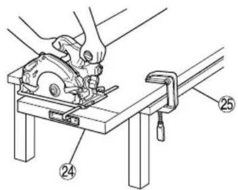
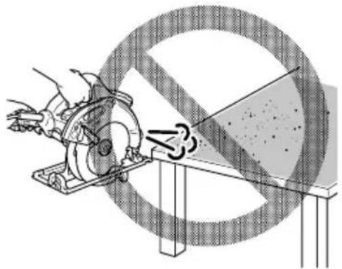
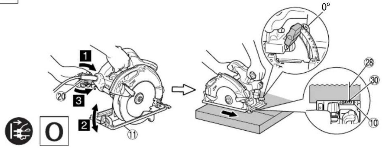
Since the saw blade will extend beyond the lower surface of the lumber, place the lumber on a workbench when cutting. If a square block is utilized as a workbench, select level ground to ensure it is properly stabilized. An unstable workbench will result in hazardous operation. (Fig. 3)
To avoid possible accident, always ensure that the portion of lumber remaining after cutting is securely anchored or held in position.
-
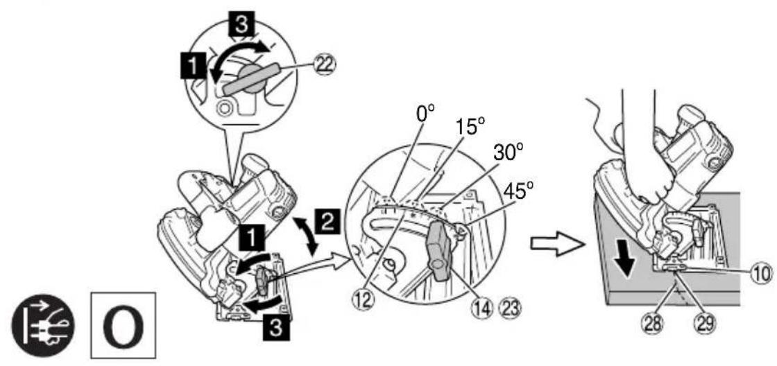
Should knob remain loosened, it will create a very hazardous situation. Always thoroughly clamp it. (Fig. 4)
-
It is very hazardous to allow wing bolt to remain loosened. Always thoroughly clamp it. (Fig. 5)
-
Prior to cutting operation, make sure the material you are going to cut. If the material to be cut is expected to generate harmful / toxic dusts, make sure the dust bag or appropriate dust extraction system is connected with dust outlet tightly.
Wear the dust mask additionally, if available.
Before starting to saw, confirm that the saw blade has attained full-speed revolution.
- Should the saw blade stop or make an abnormal noise while operating, promptly turn OFF the switch.
○ Always take care in preventing the power cord from coming near to the revolving saw blade.
○ Using the circular saw with the saw blade facing upwards or sideways is very hazardous. Such uncommon applications should be avoided.
○ When cutting materials, always wear protective glasses.
○ When finished with a job, pull out the plug from the receptacle.
-
After having attached the saw blade, reconfirm that the lock lever is firmly secured in the prescribed position.
-
Models C6U3, C6BU3, C7U3 and C7BU3 are equipped with a blower function. However, do not use the tool for the blower function only. (Fig. 8)
-
Check that there are no nicks or scratches in the cord.
-
Check the exterior and ensure that there is no damage.
-
Use a chip saw that is for cutting wood.
-
Use a chip saw with a displayed speed that is equal to or higher than the rotation speed displayed on the tool.
-
Do not leave the saw placed on top of the guide rail.
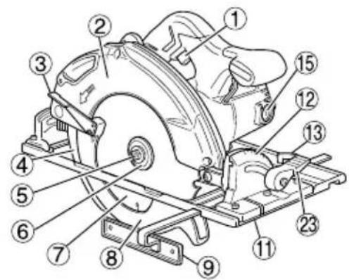
NAME OF PARTS (Fig. 1 – Fig. 23)
| 1 | Switch trigger Incline wing-out | M4 screw Machine screw | M5x12 | 40 | ||
| 2 | Saw cover Brush cap Premarked line Guide rail adapter | 28 | 41 | |||
| 3 | Lower guard lever Handle | 16 | 29 | Front scale at 45° incline | ||
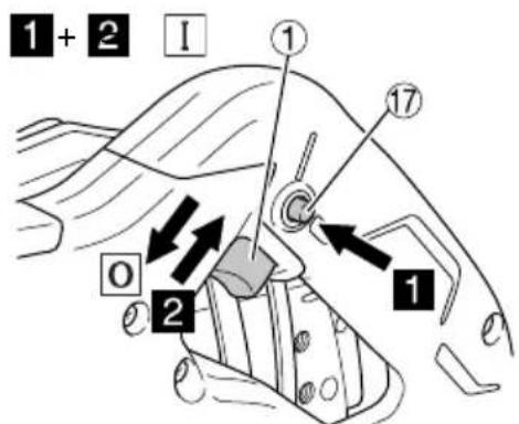
| 4 | Riving knife | 17 | Lock-off button | 30 | Front scale when not inclined | |
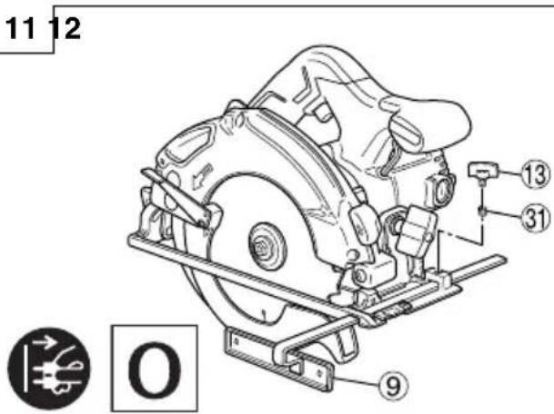
| 5 | M8 bolt | 18 | Lock lever | 31 | Lock spring | |
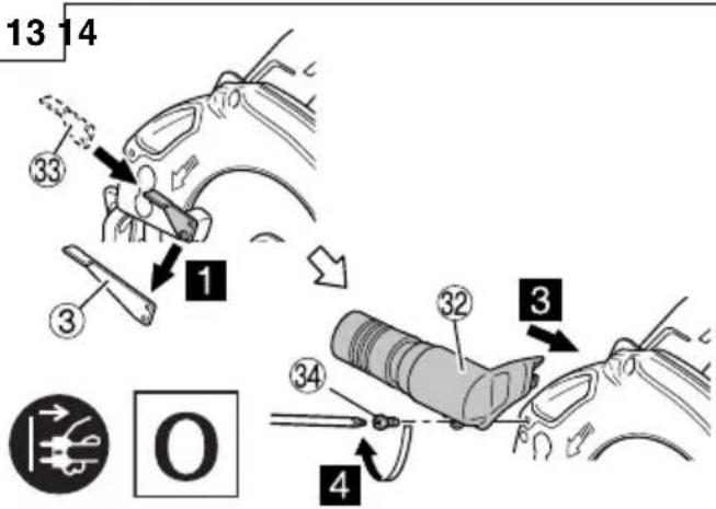
| 6 | Washer (B) | 19 | Nameplate | 32 | Dust collecor | |
| 7 | Saw blade Knob | 20 | Lever (short type) | 46 | Base square socket | |
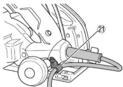
| 8 | Lower guard | 21 | Cord holder | 34 | M4 Screw | |
| 9 | Guide | 22 | Incline wing-bolt | 35 | M5 Screw | |
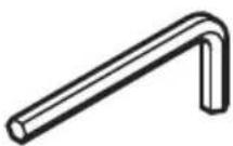
| 10 | Guide piece | 23 | Inclined lever | 36 | 6 mm Hex. bar wrench | |
| 11 | Base | 24 | Lumber | 37 | Washer (A) | |
| 12 | Inclined gauge | 25 | Workbench | 38 | Guide rail | |
| 13 | Guide fastener wing-bolt | 26 | M8 bolt | 39 | Rubber lip | |
SYMBOLS
WARNING
The following show symbols used for the machine.
Be sure that you understand their meaning before use.
 | C6U3 / C6BU3 / C6UM / C6BUM / C7U3 / C7BU3 / C7UM / C7BUM : Circular Saw |
 | To reduce the risk of injury, user must read instruction manual. |
 | Always wear eye protection. |
 | Always wear hearing protection. |
  | Only for EU countriesDo not dispose of electric tools together with household waste material!In observance of European Directive 2012/19/EU on waste electrical and electronic equipment and its implementation in accordance with national law, electric tools that have reached the end of their life must be collected separately and returned to an environmentally compatible recycling facility. |
| V | Rated voltage |
 | Cutting depth |
| P | Power Input |
| n_0 | No-Load speed |
| [YGH9] | Weight (without cord) |
 | Switching ON |
 | Switching OFF |
 | Disconnect mains plug from electrical outlet |
 | Blower |
 | Prohibited action |
 | Class II tool |
STANDARD ACCESSORIES
In addition to the main unit (1 unit), the package contains the accessories listed in the below.
○ Saw Blade (mounted on tool) ......1
Dia. 165 mm ......C6U3, C6BU3, C6UM, C6BUM Dia. 190 mm ......C7U3, C7BU3, C7UM, C7BUM
○ Hex. Bar wrench ....1
○ Guide 1
○ Wing-bolt 1
○ Lock Spring 1
○ Lever (short type) ....1
○ Dust collector ....1
Standard accessories are subject to change without notice.
APPLICATIONS
Cutting various types of wood.
SPECIFICATIONS
The specifications of this machine are listed in the Table on page 142.
NOTE
Due to HiKOKI's continuing program of research and development, the specifications herein are subject to change without prior notice.
MOUNTING AND OPERATION
| Action Figure Page | ||
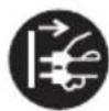
| Adjusting the cutting depth 4 143 | ||
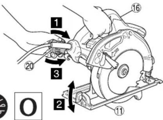
| Adjusting the angle of inclination 5 143 | ||
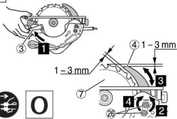
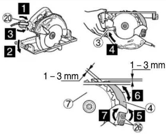
| Adjusting the riving knife (C6U3, C6BU3, C6UM, C6BUM) | 6 143 | |
| Adjusting the riving knife (C7U3, C7BU3, C7UM, C7BUM) | 7 144 | |
| Do not use the tool with only the blower function. (C6U3, C6BU3, C7U3 and C7BU3 only) | 8 144 | |
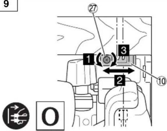
| Adjusting the guide piece (C6U3, C6BU3, C7U3 and C7BU3 only) | 9 144 | |
| Cutting line 10 144 | ||
| Regulating the guide 11 144 | ||
| Using the cord holder 12 144 | ||
| Mounting the dust collector set 13 144 | ||
| Switch operation*1 | 14 144 | |
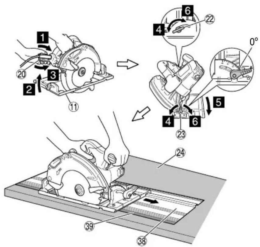
| Cutting at right angles 15 145 | ||
| Inclined cutting (+45° direction) 16 145 | ||
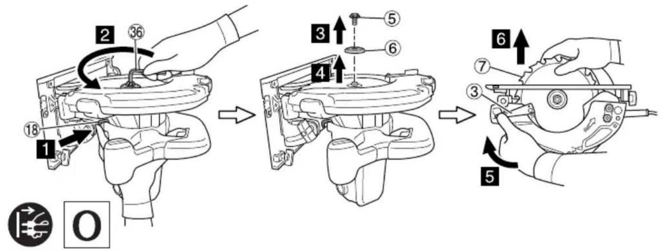
| Dismounting the saw blade 17 145 | ||
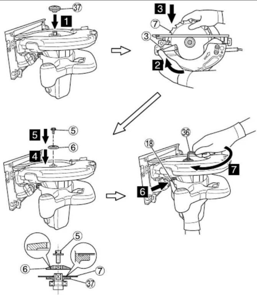
| Mounting the Saw Blade*2 | 18 146 | |
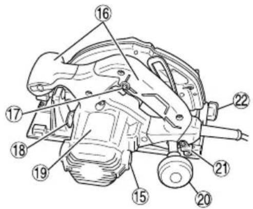
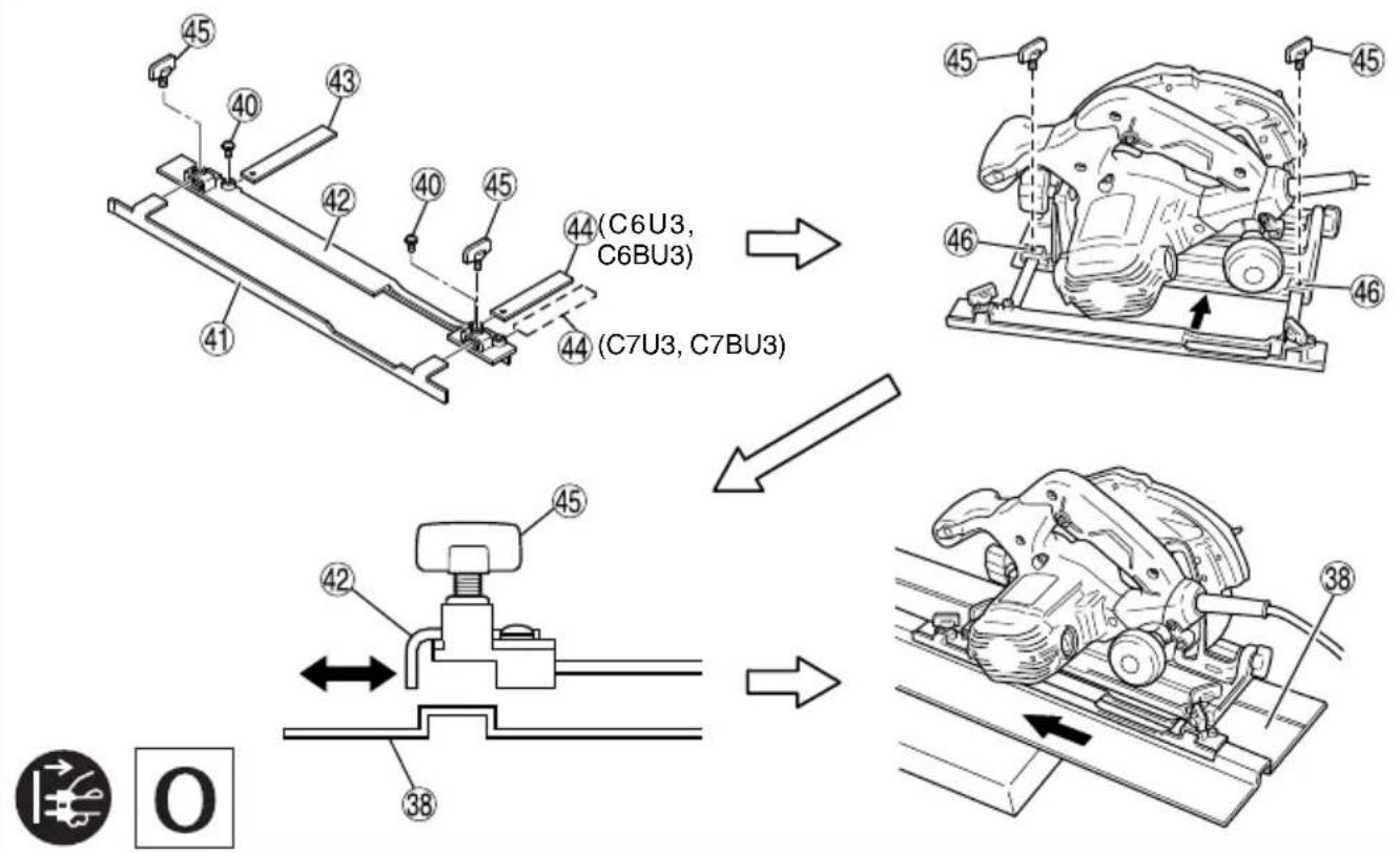
| Using the guide rail*3 (C6UM, C6BUM, C7UM and C7BUM only) (optional accessories) | 19 146 | |
| Using the guide rail adapter*4 (C6U3, C6BU3, C7U3 and C7BU3 only) (optional accessories) | 20 147 | |
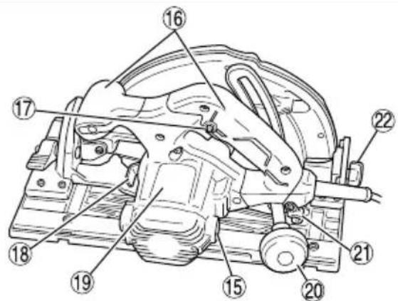
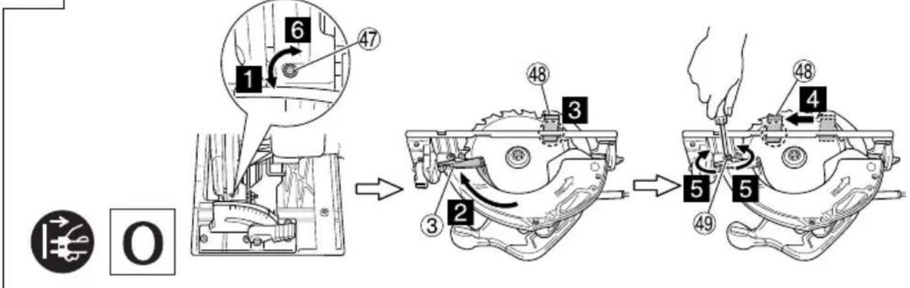
| Adjusting the base and saw blade to maintain parallelism (C6UM, C6BUM, C7UM and C7BUM only) | 21 147 | |
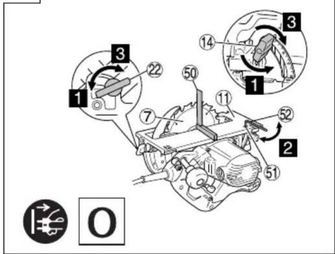
| Adjusting the base and saw blade to maintain perpendicularity (C6U3, C6BU3, C7U3 and C7BU3 only) | 22 147 | |
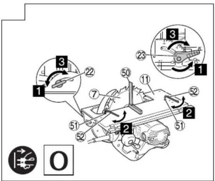
| Adjusting the base and saw blade to maintain perpendicularity (C6UM, C6BUM, C7UM and C7BUM only) | 23 147 | |
| Selecting accessories — 149 |
*1 Before beginning work, check to ensure that operating the switch correctly turns the tool ON and OFF. While the tool is plugged in to the receptacle, ensure that the sawblade stops when the switch is turned OFF. In some regions, it is not necessary to perform step 1.
*2 Usable sawblade diameter:
C6U3, C6BU3, C6UM, C6BUM ..... 165 to 162 mm
C7U3, C7BU3, C7UM, C7BUM ..... 190 to 185 mm
Body thickness: up to 1.5 mm, tip width: at least 1.9 mm
Riving knife thickness: 1.8 mm
*3 Use the guide rail when cutting in long, straight lines. The rubber lip of the guide rail works to prevent splintering on the cut surface. When using the guide rail
for the first time, cut the rubber lip as follows: Set the tool's cutting depth to the maximum and the saw blade angle to perpendicular (0°), pull the switch completely, and cut at a slow, constant speed.
After the rubber lip is cut, it can also be used for 45^ angle cutting.
*4 Use with C6U3, C6BU3, C7U3 and C7BU3 when using the guide rail.
NOTE
When performing cutting operation using the guide rail, remember that the cutting depth decreases as the thickness of the guide rail increases.
MAINTENANCE AND INSPECTION
1. Inspecting the saw blade
Since use of as dull saw blade will degrade efficiency and cause possible motor malfunction, sharpen or replace the saw blade as soon as abrasion is noted.
2. Inspecting the mounting screws
Regularly inspect all mounting screws and ensure that they are properly tightened. Should any of the screws be loose, retighten them immediately. Failure to do so could result in serious hazard.
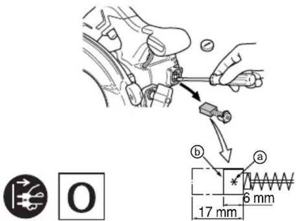
3. Inspecting the carbon brushes (Fig. 24)
The motor employs carbon brushes which are consumable parts. Since an excessively worn carbon brush can result in motor trouble, replace the carbon brushes with new ones having the same carbon brush No. ① shown in the figure when it becomes worn to or near the “wear limit” ②. In addition, always keep carbon brushes clean and ensue that they slide freely within the brush holders.
CAUTION
When replacing the new carbon brushes, always use genuine HiKOKI carbon brushes with the number specified in the drawing.
☐ For models C6BU3, C6BUM, C7BU3 and C7BUM, the brake may not work if other than the specified carbon brushes are used.
When the brake becomes ineffective, replace the carbon brushes with new ones.
4. Replacing carbon brushes
Disassemble the brush caps with a slotted-head screwdriver. The carbon brushes can then be easily removed.
5. Replacing supply cord
If the replacement of the supply cord is necessary, this has to be done by the manufacturer of this agent in order to avoid a safety hazard.
6. Motor unit maintenance
The motor winding is an important part of this tool. Avoid damaging and be careful to avoid contact with cleaning oil or water.
After 50 hours of use, clean the motor by blowing into the ventilation holes of the motor housing with dry air from an air gun or other tool (Fig. 25).
Dust or particle accumulation in the motor can result in damage.
7. Inspecting and maintaining the lower guard
Always make sure that the lower guard moves smoothly. In the event of any malfunction, immediately repair the lower guard.
For cleaning and maintenance, use an air gun or other tool to blow clean the space between the lower guard and gear cover as well as the rotation part of the lower guard with dry air (Fig. 25).
Doing so is effective for the emission of chips or other particles.
Accumulation of chips or other particles around the lower guard may result in malfunction or damage.
WARNING
To prevent dust inhalation or eye irritation, wear protective safety goggles and a dust mask when using an air gun or other tool to clean the lower guard, ventilation holes or other parts of the product.
Ensure smooth movement of lower guard
Rotation part of the lower guard
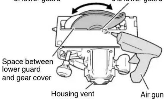
Fig. 25
CAUTION
In the operation and maintenance of power tools, the safety regulations and standards prescribed in each country must be observed.
GUARANTEE
We guarantee HiKOKI Power Tools in accordance with statutory/country specific regulation. This guarantee does not cover defects or damage due to misuse, abuse, or normal wear and tear. In case of complaint, please send the Power Tool, undismantled, with the GUARANTEE CERTIFICATE found at the end of this Handling instruction, to a HiKOKI Authorized Service Center.
IMPORTANT
Correct connection of the plug
The wires of the main lead are coloured in accordance with the following code:
Blue: — Neutral
Brown: — Live
As the colours of the wires in the main lead of this tool may not correspond with the coloured markings identifying the terminals in your plug proceed as follows:
The wire coloured blue must be connected to the terminal marked with the letter N or coloured black. The wire coloured brown must be connected to the terminal marked with the letter L or coloured red. Neither core must be connected to the earth terminal.
NOTE
This requirement is provided according to BRITISH STANDARD 2769: 1984.
Therefore, the letter code and colour code may not be applicable to other markets except The United Kingdom.
Information concerning airborne noise and vibration
The measured values were determined according to EN62841 and declared in accordance with ISO 4871.
Measured A-weighted sound power level: 109 dB (A)
Measured A-weighted sound pressure level: 98 dB (A)
Uncertainty K: 3 dB (A).
Wear hearing protection.
Vibration total values (triax vector sum) determined according to EN62841.
Cutting chipboard:
Vibration emission value ah = 2.5 m/s²
Uncertainty K = 1.5 m/s2
The declared vibration total value has been measured in accordance with a standard test method and may be used for comparing one tool with another.
It may also be used in a preliminary assessment of exposure.
WARNING
☐ The vibration emission during actual use of the power tool can differ from the declared total value depending in the ways in which the tool is used.
○ Identify safety measures to protect the operator that are based on an estimation of exposure in the actual conditions of use (taking account of all parts of the operating cycle such as the times when the tool is switched off and when it is running idle in addition to the trigger time).
NOTE
Due to HiKOKI's continuing program of research and development, the specifications herein are subject to change without prior notice.
ALLGEMEINE
VEILIGHEIDSWAARSCHUWINGEN
SIKKERHETSFORHOLDSREGLER FOR ELEKTROVERKT∅Y
ADVARSEL
VEDLIKEHOLD OG INSPEKSJON
1. Inspisere sagbladet
C6U3, C6BU3, C7U3, C7BU3
2
C6UM, C6BUM, C7UM, C7BUM
3
4
5
6

7
8
natural_image
Diagram of a cutting machine with a circular blade and diagonal line, showing no text or symbols9
10

15
16
17
18

19
20
21
22 23
24
| C6U3C6UMC7U3C7BU3 (110V)C7UM | C6BU3C6BUMC7BU3 (230V)C7BUM | |
| a | 43 56 |


370272
natural_image
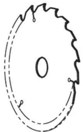
Simple line drawing of a circular object with internal markings and dashed outlines (no text or symbols)C6U3 / C6BU3 / C6UM / C6BUM: 324678
C7U3 / C7BU3 / C7UM / C7BUM: 324668
370279 324662

natural_image
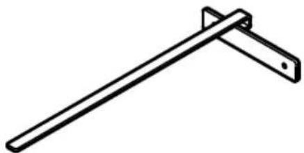
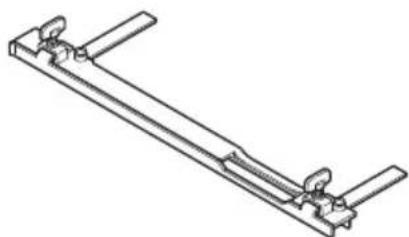
Simple line drawing of a diagonal metal rod with a support bracket (no text or symbols)370587
872422 370264
997247
natural_image
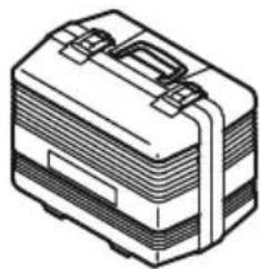
Line drawing of a suit case with straps and handle (no text or symbols)370664
natural_image
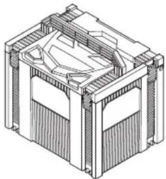
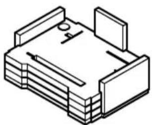
Technical line drawing of a mechanical housing or enclosure with internal components (no text or symbols)337528
natural_image
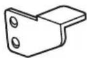
Technical line drawing of a mechanical clamp or bracket assembly (no text or symbols)C6U3 / C6BU3: 330998
C7U3 / C7BU3: 331762
natural_image
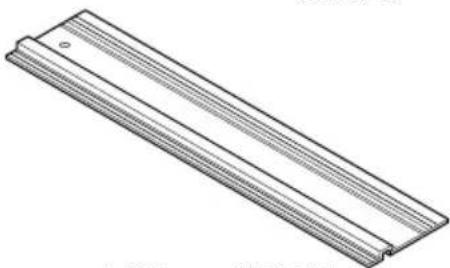
Technical line drawing of a rectangular metal profile with parallel grooves (no text or symbols)1400 mm: 370106
800 mm: 370105
natural_image
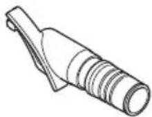
Isometric line drawing of a mechanical or architectural component with no visible text or symbolsC7UM / C7BUM / C6UM / C6BUM: 370588
natural_image
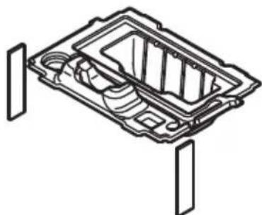
Technical line drawing of a mechanical component with internal cavities and mounting brackets (no text or symbols)C7U3 / C7BU3 / C6U3 / C6BU3: 376125
natural_image
Line drawing of a quill pen with inkwell (no text or symbols)| English Dansk Română | ||||
| GUARANTEE CERTIFICATE1 Model No.2 Serial No.3 Date of Purchase4 Customer Name and Address5 Dealer Name and Address(Please stamp dealer name and address) | GARANTIBEVIS1 Modelnummer2 Serienummer3 Købsdato4 Kundes navn og adresse5 Forhandlers navn og adresse(Indsæt stempel med forhandlers navn og adresse) | CERTIFICAT DE GARANTIE1 Model nr.2 Nr. de serie3 Data cumpărării4 Numele și adresa cliențului5 Numele și adresa distribuitorului(Vă rugăm aplicati ștampila cu numele și adresa distribuitorului) | ||
| Deutsch Norsk Slovenščina | ||||
| GARANTIESCHEIN1 Modell-Nr.2 Serien-Nr.3 Kaufdatum4 Name und Anschrift des Kunden5 Name und Anschrift des Händlers(Bitte mit Namen und Anschrift des Handlers abstempeln) | GARANTISERTIFIKAT1 Modellnr.2 Serienr.3 Kjøpsdato4 Kundens navn og adresse5 Forhandlerens navn og adresse(Vennligst stempel forhandlerens navn og adresse) | GARANCIJSKO POTRDILO1 Št. modela2 Serijska št.3 Datum nakupa4 Ime in naslov kupca5 Ime in naslov prodajalca(Prosimo visnite žig z imenom in naslovom prodajalca) | ||
| Français Suomi Slovenčina | ||||
| CERTIFICAT DE GARANTIE1 No. de modèle2 No de série3 Date d'achat4 Nom et adresse du client5 Nom et adresse du revendeur(Cachet portant le nom et l'adresse du revendeur) | TAKUUTODISTUS1 Malli nro2 Sarja nro3 Ostopäivämäärä4 Asiakkaan nimi ja osoite5 Myyjän nimi ja osoite(Leimaa myyjän nimi ja osoite) | ZÁRUČNÝ LISTA1 Č. modelu2 Sériové č.3 Dátum zakúpenia4 Meno a adresa zákaznika5 Názov a adresa predajcu(Pečiatka s názvom a adresou predajcu) | ||
| Italiano Ελληνικά Български | ||||
| CERTIFICATO DI GARANZIA1 Modello2 N° di serie3 Data di acquisto4 Nome e indirizzo dell'acquirente5 Nome e indirizzo del rivenditore(Si prega di apporre il timbro con questi dati) | ПІЕТОПОІНТИКО ЕГГУНЗНΣ1 Ap. Movтёлou2 Auξων Ap.3 Нμερομηνία αγοράς4 О́оума кαι διεύθυνση πελάτη5 О́оума кαι διεύθυνση μεταπωλητή(Паракалоўме va χρησιμοποιηθεί σφραγίδα) | ГАРАНЦИОНЕН СЕРТИФИКАТ1 Модел No2 Сериен No3 Дата за закупуване4 Име и адрес на клиента5 Име и адрес на търговеца(Моля, отпечатайте името и адрес на дилъра) | ||
| Nederlands Polski Srpski | ||||
| GARANTIEBEWIJS1 Modelnummer2 Seriennummer3 Datum van aankoop4 Naam en adres van de gebruiker5 Naam en adres van de handelaar(Stempel a.u.b. naam en adres vande de handelaar) | GWARANCJA1 Model2 Numer seryjny3 Data zakupu4 Nazwa klienta i adres5 Nazwa dealera i adres(Pieczęć punktu sprzedažy) | GARANTNI SERTIFIKAT1 Br. modela.2 Serijski br.3 Datum kupovine4 Ime i adresa kupca5 Ime i adresa prodavca(Molimo da stavite pečat na ime i adresu trgovca) | ||
| Español Magyar Hrvatski | ||||
| CERTIFICADO DE GARANTÍA1 Número de modelo2 Número de serie3 Fecha de adquisición4 Nombre y dirección del cliente5 Nombre y dirección del distribuidor(Se ruega poner el sello del distribuidor con su nombre y dirección) | GARANCIA BIZONYLAT1 Tipusszám2 Sorozatszám3 A vásárlás dátuma4 A Vásárló neve és címe5 A Kereskedő neve és címe(Kérjük ide elhelyezni a Kereskedő nevének és címěnek pecsétjét) | JAMSTVENI CERTIFIKAT1 Br modela.2 Serijski br.3 Datum kupnje4 Ime i adresa kupca5 Ime i adresa trgovca(Molimo stavite pečat na ime i adresu trgovca) | ||
| Português Čeština | ||||
| CERTIFICADO DE GARANTIA1 Número do modelo2 Número do série3 Data de compra4 Nome e morada do cliente5 Nome e morada do distribuidor(Por favor, carimbe o nome e morada do distribuidor) | ZÁRUČNÍ LIST1 Model č.2 Série č.3 Datum nákupu4 Jméno a adresa zákazníka5 Jméno a adresa prodejce(Prosíme o razitko se jménem a adresou prodejce) | |||
| Svenska Türkçe | ||||
| GARANTICERTIFIKAT1 Modellnr2 Serienr3 Inköpsdatum4 Kundens namn och adress5 Försäljarens namn och adress(Stàmpla försäljarens namn och adress) | GARANTI SERTÍFÍKASI1 Model No.2 Seri No.3 Satin Alma Tarihi4 Müşteri Adi ve Adresi5 Bayi Adi ve Adresi(Lütfen bayi adini ve adresini kaşe olarak basin) | |||
HiKOKI
| 1 | |
| 2 | |
| 3 | |
| 4 | |
| 5 |
Siemensring 34, 47877 willich, Germany
Tel: +49 2154 49930
Fax: +49 2154 499350
URL: http://www.hikoki-powertools.de
Hikoki Power Tools Netherlands B.V.
Brabanthaven 11, 3433 PJ Nieuwegein, The Netherlands
Tel: +31 30 6084040
Fax: +31 30 6067266
URL: http://www.hikoki-powertools.nl
Hikoki Power Tools (U.K.) Ltd.
Precedent Drive, Rooksley, Milton Keynes, MK 13, 8PJ,
United Kingdom
Tel: +44 1908 660663
Fax: +44 1908 606642
URL: http://www.hikoki-powertools.uk
Hikoki Power Tools France S.A.S.
Hikoki Power Tools Belgium N.V./S.A.
Koningin Astridlaan 51, B-1780 Wemmel, Belgium
Tel: +32 2 460 1720
Fax: +32 2 460 2542
URL http://www.hikoki-powertools.be
Hikoki Power Tools Italia S.p.A
Via Piave 35, 36077, Altavilla Vicentina (VI), Italy
Tel: +39 0444 548111
Fax: +39 0444 548110
URL: http://www.hikoki-powertools.it
Hikoki Power Tools Ibérica, S.A.
C/ Puigbarral, 26-28, Pol. Ind. Can Petit, 08227 Terrassa
(Barcelona), Spain
Tel: +34 93 735 6722
Fax: +34 93 735 7442
URL: http://www.hikoki-powertools.es
Kjeller Vest 7, N-2007 Kjeller, Norway
Tel: (+47) 6692 6600
Fax: (+47) 6692 6650
URL: http://www.hikoki-powertools.no
Hikoki Power Tools Sweden AB
Rotebergsvagen 2B SE-192 78 Sollentuna, Sweden
Tel: (+46) 8 598 999 00
Fax: (+46) 8 598 999 40
URL: http://www.hikoki-powertools.se
Hikoki Power Tools Denmark A/S
Lillebaeltsvej 90, 6715 Esbjerg N, Denmark
Tel: (+45) 75 14 32 00
Fax: (+45) 75 14 36 66
URL: http://www.hikoki-powertools.dk
Hikoki Power Tools Finland Oy
Tupalankatu 9, 15680 Lahti, Finland
Tel: (+358) 20 7431 530
Fax: (+358) 20 7431 531
URL: http://www.hikoki-powertools.fi
Hikoki Power Tools Hungary Kft.
Hikoki Power Tools Romania S.R.L.
Ring Road, No. 66, Mustang Traco Warehouses, Warehouse
No.1, Pantelimon City, 077145, Ilfov County, Romania

- GENERAL POWER TOOL SAFETY WARNINGS
- WARNING
- 1) Work area safety
- 2) Electrical safety
- 3) Personal safety
- 4) Power tool use and care
- PRECAUTION
- SAFETY INSTRUCTIONS FOR ALL SAWS
- Cutting procedures
- Kickback causes and related warnings
- Lower guard function
- English
- Riving knife function
- ADDITIONAL SAFETY WARNINGS
- SYMBOLS
- STANDARD ACCESSORIES
- APPLICATIONS
- SPECIFICATIONS
- NOTE
- MAINTENANCE AND INSPECTION
- Inspecting the saw blade
- Inspecting the mounting screws
- Inspecting the carbon brushes (Fig. 24)
- CAUTION
- Replacing carbon brushes
- Replacing supply cord
- Motor unit maintenance
- Inspecting and maintaining the lower guard
- GUARANTEE
- IMPORTANT
- Information concerning airborne noise and vibration
- ALLGEMEINE
- VEILIGHEIDSWAARSCHUWINGEN
- SIKKERHETSFORHOLDSREGLER FOR ELEKTROVERKT∅Y
- ADVARSEL
- VEDLIKEHOLD OG INSPEKSJON
- Inspisere sagbladet
- Hikoki Power Tools Netherlands B.V.
- Hikoki Power Tools (U.K.) Ltd.
- Hikoki Power Tools France S.A.S.
- Hikoki Power Tools Belgium N.V./S.A.
- Hikoki Power Tools Italia S.p.A
- Hikoki Power Tools Ibérica, S.A.
- Hikoki Power Tools Sweden AB
- Hikoki Power Tools Denmark A/S
- Hikoki Power Tools Finland Oy
- Hikoki Power Tools Hungary Kft.
- Hikoki Power Tools Romania S.R.L.
Brand : HiKOKI
Model : C7BUM
Category : Saw