EPOS RS1 - Robot mower HUSQVARNA - Free user manual and instructions
Find the device manual for free EPOS RS1 HUSQVARNA in PDF.

| Product Type | EPOS™ reference station for robotic lawnmower |
| Brand | Husqvarna |
| Model | EPOS RS1 |
| Dimensions (L x W x H) | 17 x 16 x 22 cm |
| Weight | 0.5 kg |
| Power supply (input) | 100-240 V AC, 50-60 Hz |
| Power supply (output) | 28 V DC, 1.3 A |
| Power consumption | 2.8 W |
| Protection rating (station) | IPX5 |
| Protection rating (power supply) | IP44 |
| Operating temperature (station) | -20 °C to 45 °C |
| Operating temperature (EPOS plug-in) | 0 °C to 45 °C |
| Storage temperature | -20 °C to 70 °C |
| Length of low-voltage cable supplied | 20 m / 66 ft |
| Radio frequencies | Bluetooth® 2.4 GHz, SRD868 (863-870 MHz) |
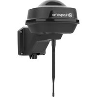
| Main function | Receiving satellite signals and sending correction data to the robotic lawnmower |
| Recommended installation | On a mast or wall, at a minimum height of 2 m, with a clear view of the sky over 135° |
| Maximum distance station-robot | 100 m / 330 ft |
| Maintenance | Clean with a damp cloth; do not use a pressure washer |
| Safety | Disconnect power before maintenance; use only the supplied Husqvarna power supply |
| Spare parts | Use original Husqvarna parts |
| General information | Serial number on the rating plate; register at www.husqvarna.com |
Frequently Asked Questions - EPOS RS1 HUSQVARNA
User questions about EPOS RS1 HUSQVARNA
0 question about this device. Answer the ones you know or ask your own.
Ask a new question about this device
Download the instructions for your Robot mower in PDF format for free! Find your manual EPOS RS1 - HUSQVARNA and take your electronic device back in hand. On this page are published all the documents necessary for the use of your device. EPOS RS1 by HUSQVARNA.
USER MANUAL EPOS RS1 HUSQVARNA
EN Operator's manual 2-25
SV Bruksanvisning 26-49
DA Brugsanvising 50-73
1 Safety. 2
2 Introduction. 3
3 Installation 6
4 Maintenance. 19
5 Troubleshooting. 19
6 Storage and disposal. 23
7 Technical data. 24
8 Declaration of Conformity. 25
1 Safety
1.1 Safety definitions
Warnings, cautions and notes are used to point out specially important parts of the manual.

WARNING: Used if there is a risk of injury or death for the operator or bystanders if the instructions in the manual are not obeyed.

CAUTION: Used if there is a risk of damage to the product, other materials or the adjacent area if the instructions in the manual are not obeyed.
Note: Used to give more information that is necessary in a given situation.
1.2 General safety instructions

WARNING: Read the warning instructions that follow before you use the product.
- Obey national regulations about electrical safety.
- The product is only to be used with the power supply unit supplied by Husqvarna.
- The product may only be used with the equipment recommended by the manufacturer. All other types of use are incorrect. The manufacturer's instructions with regard to operation/maintenance must be followed precisely.
- The product may only be operated, maintained and repaired by persons that are fully conversant with its special characteristics and safety regulations. Please read the Operator's Manual carefully and make sure you understand the instructions before using the product.
-
Husqvarna does not guarantee full compatibility between the product and other types of wireless systems such as remote controls, radio transmitters, hearing loops, underground electric animal fencing or similar.
-
It is not permitted to modify the original design of the product. All modifications are made at your own risk.
- Examine the product for damage before you start the product. Do not use the product if it is damaged.
- The operating temperature for the reference station is -20^ to 45^ / -4^ to 113^ . The operating temperature for the EPOS Plug-in is 0^ to 45^ / 18^ to 113^ . The storage temperature for reference station and EPOS Plug-in is -20^ to 70^ / -4^ to 158^ .
1.3 Safety instructions for installation

WARNING: Read the warning instructions that follow before you use the product.
- Do not put the power supply at a position where there is a risk that it can become wet. Do not put the power supply on the ground.
- Do not encapsulate the power supply. Condensed water can harm the power supply and increase the risk of electrical shock.
- Risk of Electric Shock. Install only to an residual-current device (RCD) when connecting the power supply to the wall socket. Applicable to USA/ Canada. If power supply is installed outdoors: Risk of Electric Shock. Install only to a covered Class A GFCI receptacle (RCD) that has an enclosure that is weatherproof with the attachment plug cap inserted or removed.
- Make sure that the plugs of the low-voltage cable and the power supply unit are clean and dry before you connect them.
- There is a risk of falling objects during the installation of the reference station. This can result in injury.
- The power supply cable and extension cable must be outside the work area to prevent damage to the cables.
- There is a risk of falling when you install the reference station in a high position. Make sure that you have a stable position when you install the reference station.
1.4 Safety instructions for maintenance

WARNING: Read the warning instructions that follow before you use the product.
- Disconnect the product from the power supply before you clean or do maintenance on the product.
1.5 In the event of a thunderstorm
To decrease the risk of damage to electrical components in the reference station, we recommend that the power supply to the reference station is disconnected if there is a risk of a thunderstorm. Connect the power supply again when there is no a risk of thunderstorm.
2 Introduction
2.1 Introduction
| Serial number: | |
| Product number: |
The serial number is on the product rating plate and on the product carton. Use the serial number to register your product on www.husqvarna.com.
2.1.1 Support
For support about the product, speak to your Husqvarna servicing dealer.
2.1.2 Product description
Note: Husqvarna regularly updates the appearance and function of the products. Refer to Support on page 3
The EPOS™ reference station receives satellite signals and sends correction data to the robotic lawn mower.
The EPOS™ Plug-in use satellite signals and the correction data from the reference station for positioning.
2.1.3 System description
The EPOS ^TM system contains a robotic lawn mower, a charging station and a reference station. The robotic lawn mower and the reference station receives satellite signals for positioning. The reference station is stationary and sends correction data to the robotic lawn mower to get an accurate position for the mower. The work area is made virtually in an app by operating the product and adding waypoints to make a map in an app.
2.1.4 Product overview
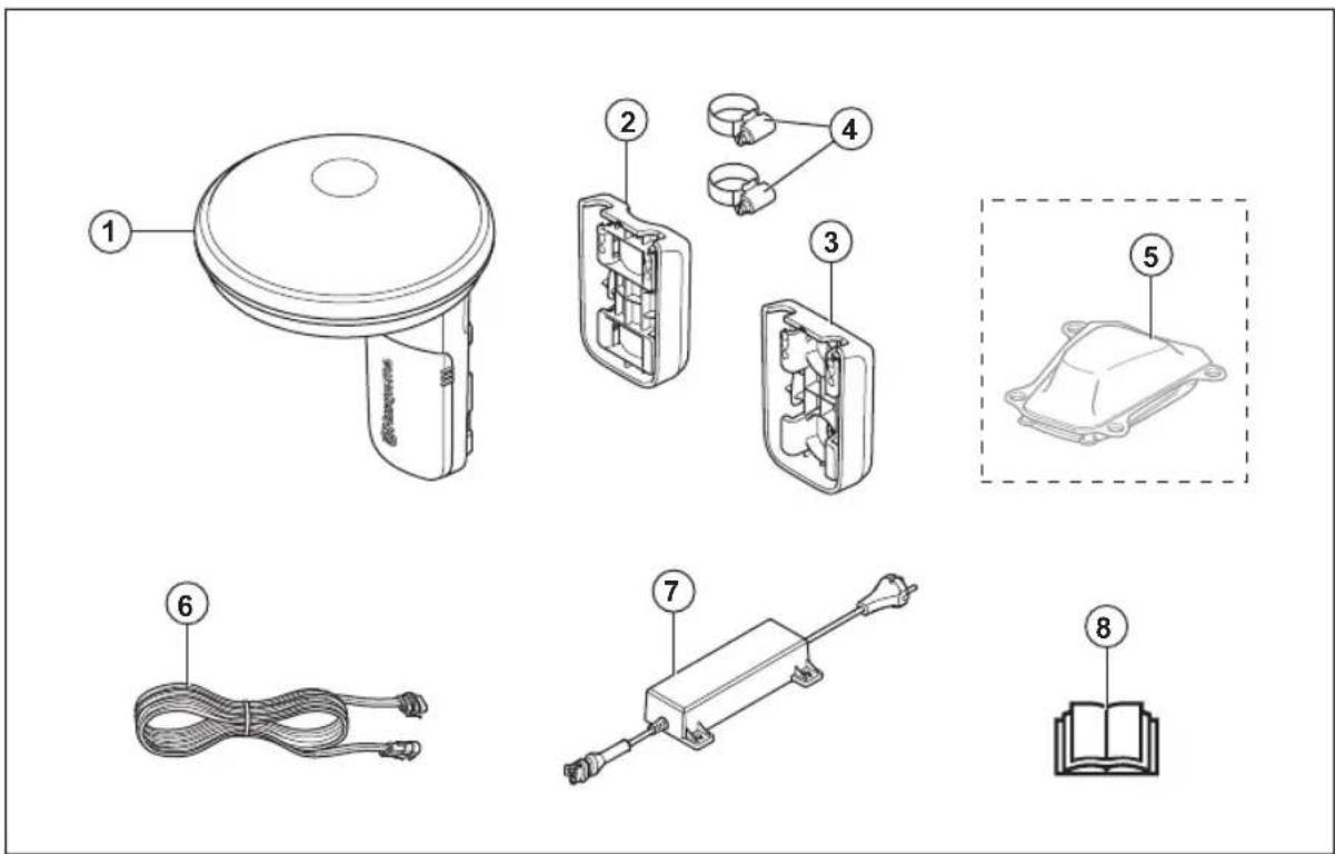
- Reference station
- Low-voltage cable
- Pole bracket
- Power supply 2
- Wall bracket
- Operator's manual
- Hose clamps
- Automower EPOS™ Plug-in
2.1.5 System overview
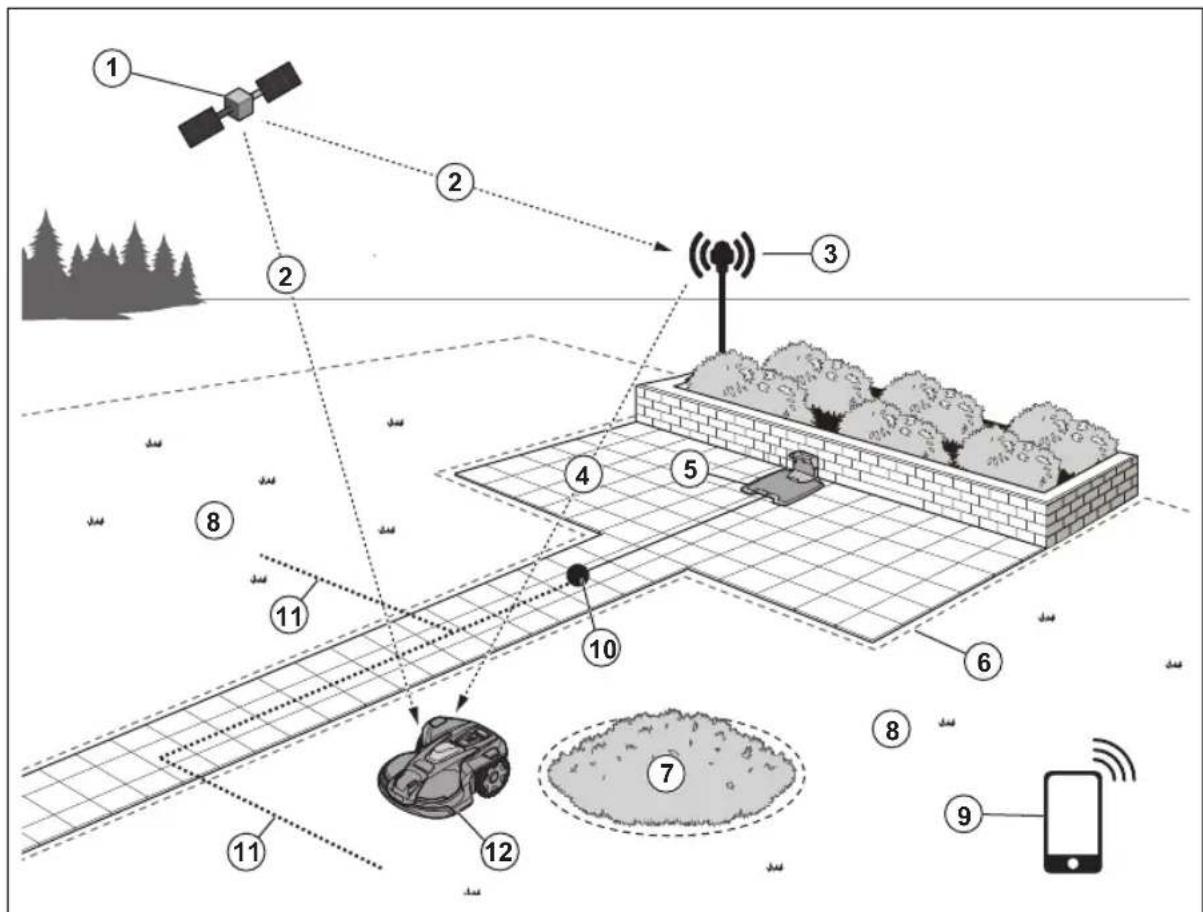
- Satellites
- Satellite signals
- Reference station
- Correction data
- Charging station 3
- Virtual boundary
- Stay-out zone
- Work area
- Mobile device 4
- Docking point
- Transport path
- Robotic lawn mower with EPOS™ Plug-in Kit5
2.1.6 Symbols on the product
These symbols can be found on the product. Make sure that you understand them.

This product complies with the applicable EU Directives.

This product complies with the applicable UK Directives.
It is not permitted to dispose the product as usual domestic waste. Obey national regulations and use the local recycling system.
Use a detachable power supply as specified on the rating plate adjacent to the symbol.
Note: Other symbols/decals on the product refer to certification requirements for some markets.
2.1.7 Symbols in the app

Shows the strength of the radio signal that the product receives from the reference station.

The status is EPOS confirmed. The product has an accurate position and direction. This is necessary to operate the product automatically and for the installation of map objects.

The status is EPOS action is necessary. The product has an accurate position but it is necessary to operate the product, manually or automatically, to get an accurate direction.

The status is EPOS searching. The product does not have an accurate position and is searching for the satellite signals and the correction data to get an accurate position.
3 Installation
3.1 Introduction - Installation

WARNING: Read and understand the safety chapter before you install the product.

WARNING: Read and understand the safety chapter in the manual for the robotic lawn mower before you install the product.

CAUTION: Use original spare parts and installation material.
Note: Refer to www.husqvarna.com for more information about installation.
3.2 Primary components for installation
The installation includes the components that follow:
- Robotic lawn mower automatically.
6, that cuts the lawn
- Charging station
, that charges the product.
Power supply unit charging static
8, which is connected to the and a 100-240V power outlet.
Power supply unit, reference stati
which is connected to the
and a 100-240V power outlet.
- Reference station, and sends corn mower.
at receives satellite signalsaction data to the robotic lawn
- Automower
EPOS Plug-in
- Mobile device with the Automower
Connect app
to do the installation and the settings for the product.
3.3 To prepare for installation

CAUTION: Holes with water in the lawn can cause damage to the product.

CAUTION: Read the installation chapter before you start the installation.
- Make a blueprint of the work area and include all obstacles. This makes it easier to examine where to put the charging station, the reference station, and the virtual boundaries.
- Make a mark on the blueprint where to put the charging station, the reference station, the maintenance point, the transport paths and the virtual boundaries for the work areas and stay-out zones.
- Follow the instructions for distances between obscuring objects.
- Fill in holes in the lawn to make it level.
- Cut the grass before you install the product. Make sure that the grass is maximum 10cm / 4 in.
Note: The first weeks after installation the sound level when the product cuts the grass can be higher than usual. The sound level decreases after some time.
3.4 To examine where to put the reference station

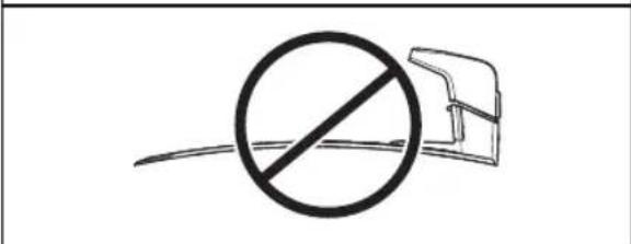
CAUTION: If there is a lightning rod near by, do not install the reference station higher than the lightning rod.

CAUTION: Do not install the reference station on a flagpole. Movements of the reference station will affect the correction data sent to the product with the accurate position.
- Install the reference station on a fixed object that cannot move or rotate.
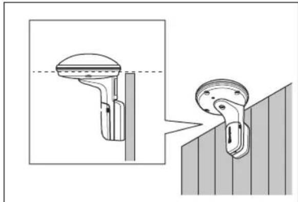
- Install the reference station on a post or a wall. The post must be 27 - 36mm /1.1-2.2 in. in diameter to fit the attachments on the reference station.
Note: If the reference station is installed on a wall the top of the reference station must be above the wall. Metal objects can cause interference with the reference station signal.
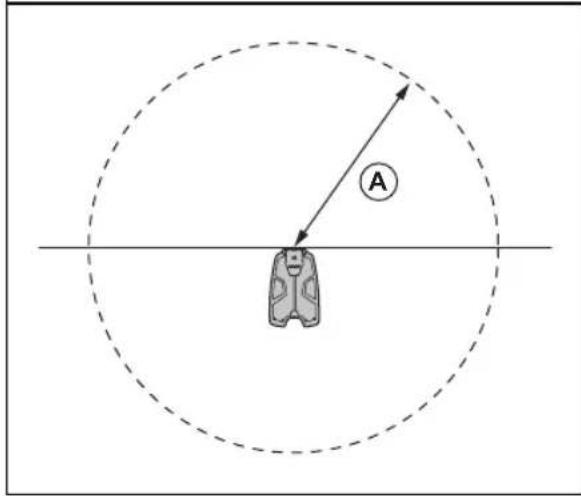
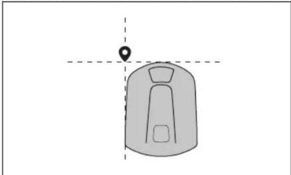
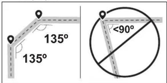
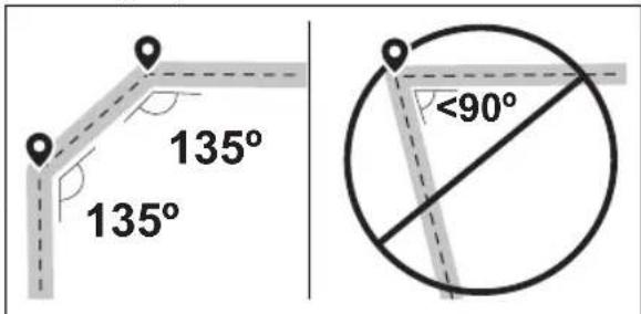
Make sure that the reference station has full view of the sky. It is necessary that minimum 135 degrees of the sky has a full view.
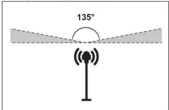
Install the reference station at minimum 2 m / 6.5 ft. height.
- Make sure that the distance between the reference station and the robotic lawn mower is less than 100m / 330 ft. Objects between the reference station and robotic lawn mower can decrease the distance.
3.5 To examine where to put the power supply
- Put the power supply in an area with a roof and protection from the sun and rain.
- Put the power supply in an area with good airflow.
- Use a residual-current device (RCD) when you connect the power supply to the power outlet.
- Extend the low-voltage cable if necessary. The low-voltage cable can be extended up to 100m / 328 ft.
3.6 To examine where to put the charging station
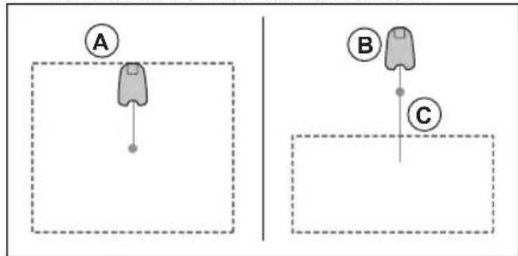
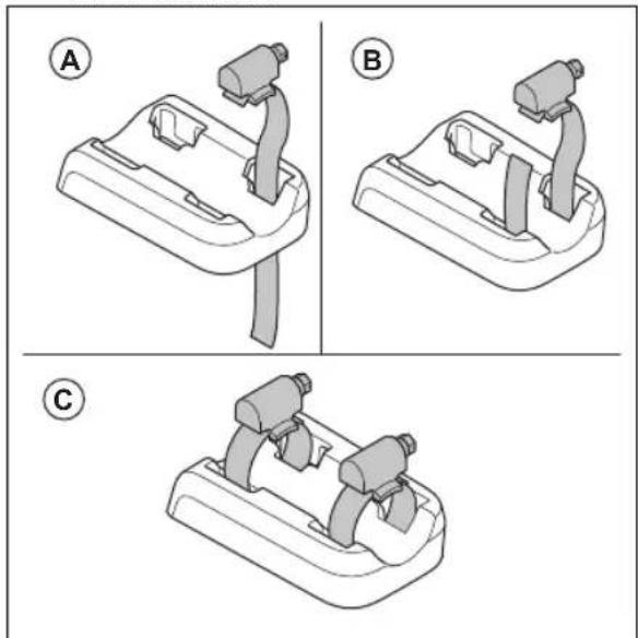
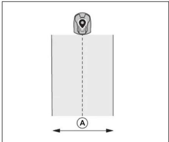
- You can put the charging station within the work area or outside the work area. No transport path is necessary if the charging station is put in the work area (A). No transport path is necessary if the product is fully in the work area when it is at the charging station docking point. If the charging station and docking point (B) are not in the work area, you must install a transport path (C).
- You can put the charging station in an Automower® house.
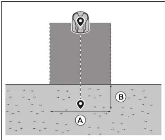
- Put the charging station (A) where the docking point (B) has unimpeded sky view. The charging station docking point (B) is where the product stops after reversing from the charging station. The reversing distance can be set to 70-250 cm / 28-98 in. Husqvarna recommends to have a minimum 6 m / 20 ft. (C) of free space in front of the charging station.

If the product must not operate in a part of the docking area, put a protective wall that is minimum 15cm / 6 in. in height. The docking area (A) is a circular area around the charging station with a radius of 3m / 9.8 ft.
Note: The product uses the charging station signal to search for the charging station when it is in the docking area.
- If the work area has 2 parts separated with a steep slope, Husqvarna recommends to put the charging station in the lower section.

CAUTION: Do not install the charging station where there are metal objects in the ground. Metal objects can cause interference with the charging station signal.
3.7 To examine where to put the power supply

CAUTION: Make sure that the blades on the product do not cut the low-voltage cable.

CAUTION: Do not put the low-voltage cable in a coil or below the charging station plate. The coil causes interference with the signal from the charging station.
- Put the power supply in an area with a roof and protection from the sun and rain.
- Put the power supply in an area with good airflow.
- Use a residual-current device (RCD) with a tripping current of maximum 30mA when you connect the power supply to the power outlet.
Low-voltage cables of different lengths are available as accessories.
3.8 To examine where to install the virtual boundaries

CAUTION: If the work area is adjacent to water bodies, slopes, precipices or a public road, there must be a protective wall. The wall must be minimum 15 cm / 6 in. in height.

CAUTION: Do not let the product operate on gravel.
- For careful operation without noise, isolate all obstacles such as trees, roots and stones.
Make a blueprint of the work area before you install the virtual boundaries.
3.9 To install map objects near buildings and trees
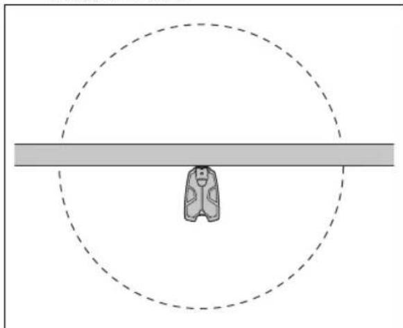
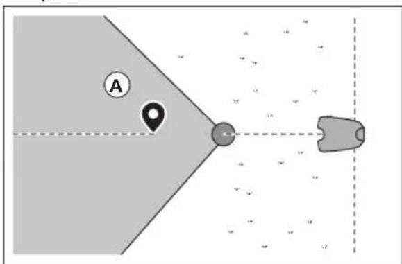
Make sure that 90^ section of the sky is unimpeded where the product operates.
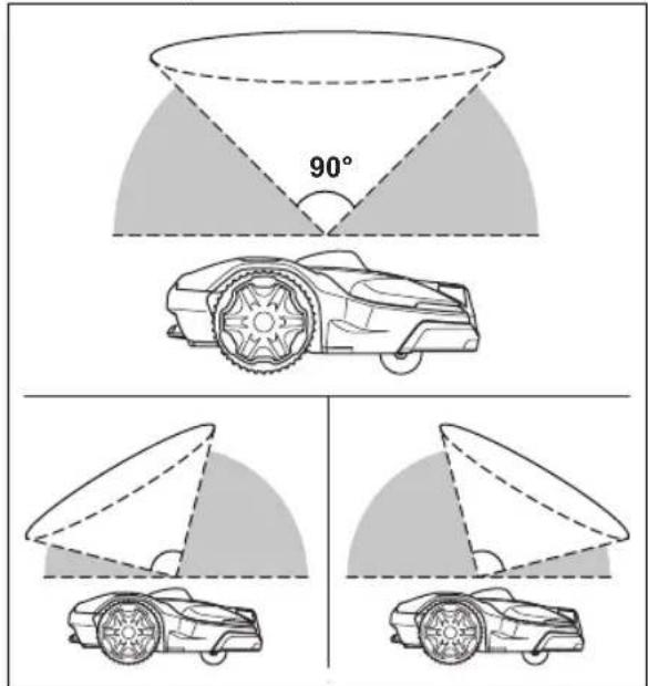
Note: The product cannot receive signals from the satellite for navigation if the sky is impeded.
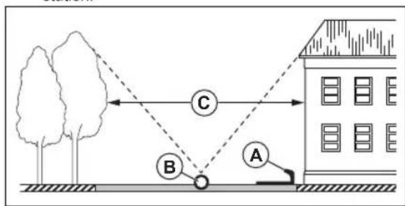
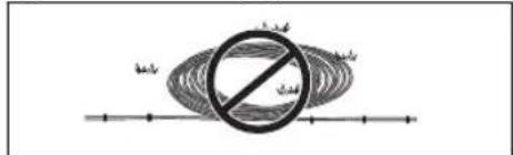
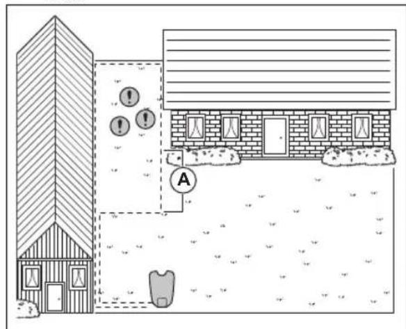
Make a stay-out zone (B) around trees or a group of trees with tree canopies that are more than 4m/ 13 ft. in diameter (A).
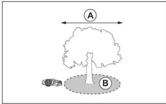
Note: Trees or a group of trees with tree canopies that are more than 4m /13 ft.in diameter (A) can cause temporary stops for the product. Smaller trees do usually not cause interference with the operation of the product.
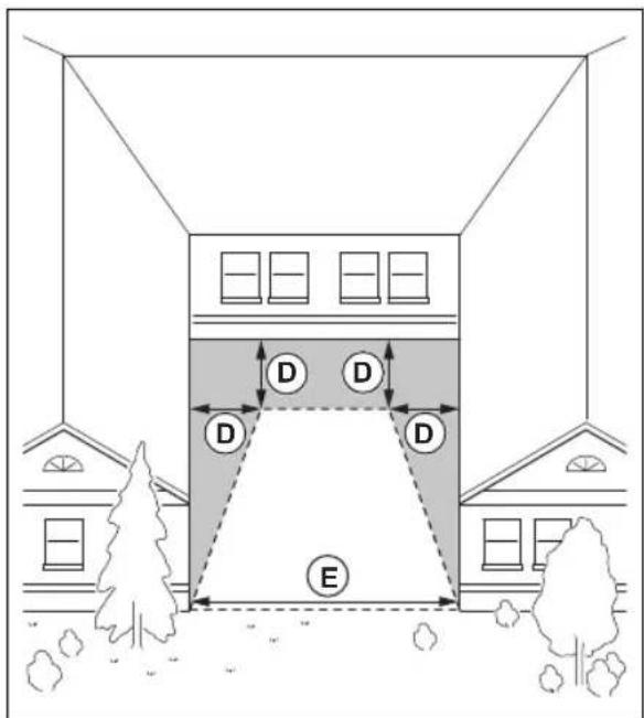
- For L-shaped buildings, install the virtual boundary at a minimum distance (C) of 1.5m / 5 ft. from it.
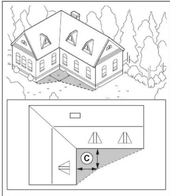
- To install virtual boundaries in an area with an U-shaped building, make sure that the distance (E) is minimum 6m / 20 ft. If the building is higher than 3 m / 10 ft., make sure that the distance (E) is twice the height of the highest building. Install the virtual boundary at a minimum distance (D) of 1.5m / 5 ft. from the building.
Make sure that the areas between objects have a distance (F) of minimum 4m / 13 ft.
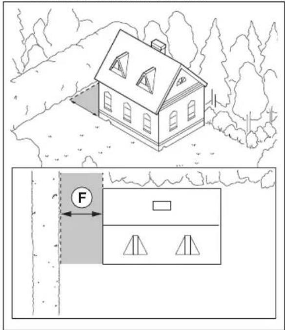
Note: For areas with a width less than 4m / 13 ft. a transport path can be made for the robotic lawn mower to go through without cutting.
3.9.1 Passages
A passage is a section that has virtual boundary on each side and that connects 2 parts of the work area. The width of the passage can be minimum 2m / 6.5 ft. to get a good cutting result.
3.9.2 To examine where to make stay-out zones
- Make stay-out zones around objects that are larger than 2 × 2 ~m / 6.6 × 6.6 ft.
Make sure that the stay-out zone includes the complete area were the product must not operate (B).
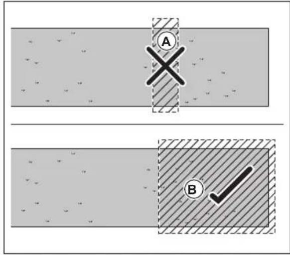
Note: Do not make a stay-out zone across the work area to prevent the product to enter parts of the work area (A).
Make sure that the stay-out zone is minimum 30 × 30 cm / 1 × 1 ft .
3.9.3 To install the map objects in a slope
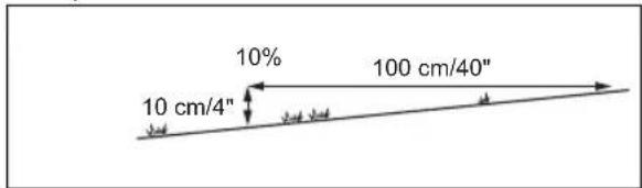
Slopes that are too steep must be isolated with the boundary wire. The gradient (%) is calculated as the vertical height divided by the horizontal distance. Example: 10cm / 100cm = 10% .
- For slopes steeper than the maximum permitted slope, do not include them in the work area. You can also isolate the slope with a stay-out zone.
- Install the virtual boundaries in slopes that are less steep than the maximum permitted slope for the virtual boundary.
- For slopes adjacent to a public road, put a barrier of minimum 15cm / 6 in. along the outer edge of the slope. You can use a wall or a fence as a barrier.
- For systematic pattern, Husqvarna recommends that you set the direction of the systematic pattern straight up the slope.
3.9.4 To use the EPOS Support by wire function
The boundary wire can be installed to operate with the EPOS system. Install the boundary wire if the satellite signals are weak. It can be in a part of the work area or an area where you have installed a transport path. Refer to the operator's manual for the robotic lawn mower on how to install the boundary wire.
Note: Do not use the boundary wire to extend the work area.

- Put a part of the boundary wire (A) approximately 2 m / 6.6 ft from the area where the satellite signal is weak.
- Enable the EPOS Support by wire function when the boundary wire is installed. Select Accessories > EPOS Support by wire > Enable in the Automower Connect app.
- Extend the boundary wire in the work area if the product continues to stop in a part of the work area.
- Extend the boundary wire in the work area if the product cannot move from the area with boundary wire.
3.10 To install the product
- Install the EPOS TM Plug-in. Refer to To install the EPOS plug-in on page 11.
- Install the Automower Connect app on your mobile device. Refer to Automower Connect on page 12.
- Do a pairing operation of the product and the Automower Connect app. Do the EPOS™ setup in the Automower Connect app. Refer to To do the EPOS™ setup on page 11.
- Install the charging station. Refer to To install the charging station on page 12.
- Install the reference station. Refer to Installation of the reference station on page 13.
- Make a map with work areas, stay-out zones, transport paths and maintenance points. Refer to Installation of the map objects on page 15.
- Use Automower Connect app to do settings for the product. Refer to Automower Connect on page 12.
Note: For more information about settings in the app, read the Operator's manual for the robotic lawn mower.
3.10.1 To install the EPOS plug-in
Follow the instructions for installation in the operator's manual for Automower® EPOS™ Plug-in.
3.10.2 To do the EPOS ^TM setup
When the product is set to ON for the first time, there are some basic settings to do before the product can start to operate. You must do a pairing operation of the product and the Automower Connect app to install objects on the map, change the settings and operate the product. Use the Automower Connect app on your mobile device or on the Automower Connect app.
- Set the product to ON.
Note: The Bluetooth® pairing operation mode of the product is enabled for 3 minutes. If the pairing operation between the product and the mobile device is not completed in 3 minutes, set the product to OFF and then set the product to ON.
- Log on to your Husqvarna account in the Automower Connect app.
- Start Bluetooth on your mobile device.
- Select My mowers in the Automower® Connect app and add your product.
- Enter the factory PIN code.
- Follow instructions for the EPOS ^TM setup in the Automower Connect app. Do a paring operation with the reference station and the charging station and install the map objects.
Note: It is only necessary to do a pairing operation of the Automower Connect app and the product one time.
3.10.3 Automower Connect
Automower Connect is a free app for your mobile device. Use the app for installation, settings and operation of your product. You can also find more information for example about alarm and statistics in the Automower Connect app.
The app gives 2 modes of connectivity: Long-range cellular connectivity and Short-range Bluetooth® connectivity.
- Dashboard that shows the current status of the product and the battery state of charge.
Note: All countries do not support cellular connection to Automower® Connect because of regional specified cellular systems. The included Automower® Connect lifetime service only applies if there is a third part subsupplier of available in the operational area.
3.10.4 Installation of the charging station
Read and understand the instructions about the charging station. Refer to To examine where to put the charging station on page 7.

CAUTION: Do not make new holes in the charging station plate.

CAUTION: Do not put your feet on the baseplate of the charging station.

WARNING: Make sure that the plugs of the low-voltage cable and the power supply unit are clean and dry before you connect them.
When you connect the power supply, only use a power outlet that is connected to a residual-current device (RCD).
3.10.4.1 To install the charging station

CAUTION: Do not make new holes in the charging station plate.

CAUTION: Do not put your feet on the baseplate of the charging station.

WARNING: Make sure that the plugs of the low-voltage cable and the power supply unit are clean and dry before you connect them.
When connecting the power supply, only use a power outlet that is connected to an residual-current (RCD) device.
- Read and understand the instructions about the charging station. Refer to To examine where to put the charging station on page 7.
- Put the charging station in the selected area.
Note: Do not attach the charging station to the ground with the screws until the guide wire is installed.
- Open the hatch on the front of the charging station.
- Attach the top of the charging station.
- Tilt the top of the charging station.
- Put the grommet with the cables into position.
- Connect the cable to the charging station.
- Connect the low-voltage cable to the charging station.
- Close the hatch on the front of the charging station.
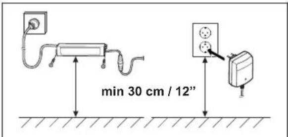
- Put the power supply at a minimum height of 30 cm / 12 in.
- Connect the power supply cable to a 100-240V power outlet.
Note: The product can be put in the charging station to charge while you install the boundary wire.
- Put the low-voltage cable in the ground with stakes or bury the cable.
- Connect the wires to the charging station after the installation of boundary wire and guide wire is complete.
- Attach the charging station to the ground with the supplied screws after the guide wire is installed.
3.10.4.2 To do a visual check of the charging station - Make sure that the indicator LED lamp on the charging station has a green light.
- If the indicator LED lamp does not have a green light, do a check of the installation. Refer to LED indicator lamp on the charging station on page 23 and To install the charging station on page 12.
3.10.5 Installation of the reference station
You can install the reference station on a post or a wall.

CAUTION: Movements of the reference station will affect the correction data sent to the product with the accurate position. The reference station must be installed tightly on the post or wall.

CAUTION: The items on the map will change position if you move the reference station. Adjust the items on the map or do the installation again in the Automower Connect app.
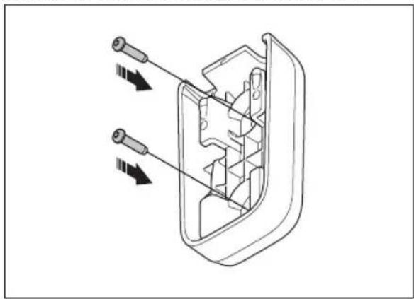
3.10.5.1 To install the bracket on a wall
Note: Screws are not included. Use screws that are applicable for the wall material.
- Hold the arm of the reference station on the wall.
Make 2 marks on the wall for the 2 screws.
Note: Make sure that the top of the reference station is above the wall.
- Drill holes at the 2 marks in the wall for the 2 screws.
- Install the bracket on the wall with the 2 screws.
3.10.5.2 To install the bracket on a pole
- Attach the pole tightly to a wall, roof top or to the ground. Make sure that the pole cannot move.
- Put the hose clamps through the slot on the rear side of the bracket.
- Attach the bracket on the pole and tighten the hose clamps with a flat screwdriver.
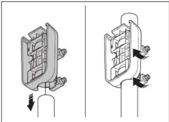
3.10.5.3 To install the reference station
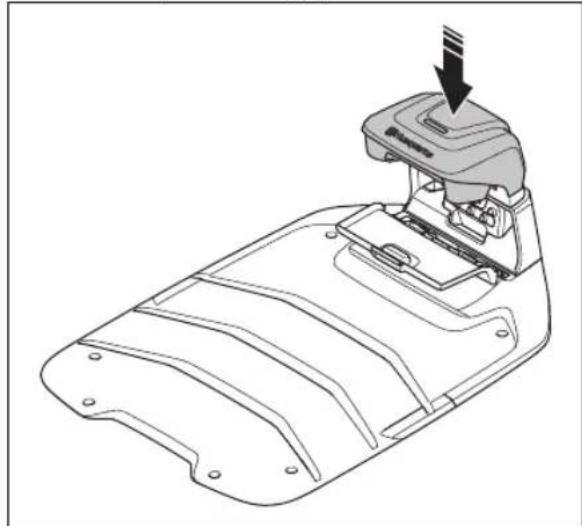
- Hold the reference station above the bracket and align the arm of the reference station with the slots in the bracket.
- Push the reference station down to attach it to the bracket.
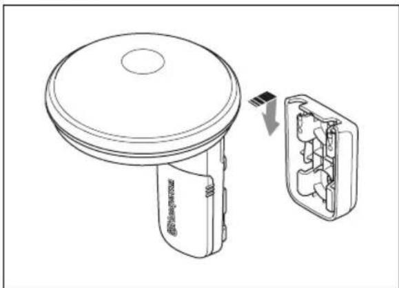
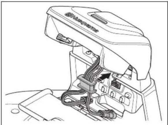
- Push and hold the cable cover and move it down to remove it from the reference station.
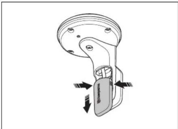
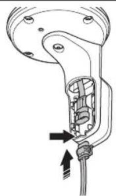
- Connect the low-voltage cable to the reference station. Put the low-voltage cable in the cable slot.
- Install the cable cover.
- Connect the low-voltage cable from the reference station to the power supply.
- Attach the low-voltage cable to the wall or pole with cable ties.

CAUTION: If the low-voltage cable is not attached tightly with cables, it can become damaged in hard wind.
- Put the power supply 30 - 200cm / 1 - 6.5 ft. above the ground. Refer to To examine where to put the power supply on page 7.
- Connect the power supply cable to a 100-240V power outlet.
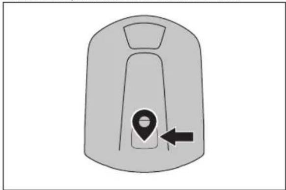
Note: The LED indicator of the reference station flashes green for some minutes. The LED indicator is solid green when the reference station is in operation. Refer to LED indicator lamp on the reference station on page 23.
3.10.6 Installation of the map objects
Read and understand the instructions about where to install the map objects. Refer to To examine where to install the virtual boundaries on page 9
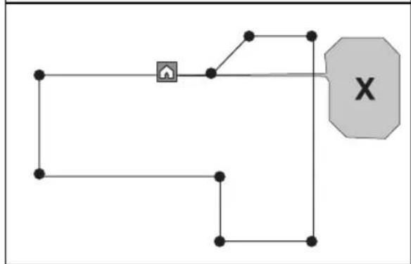
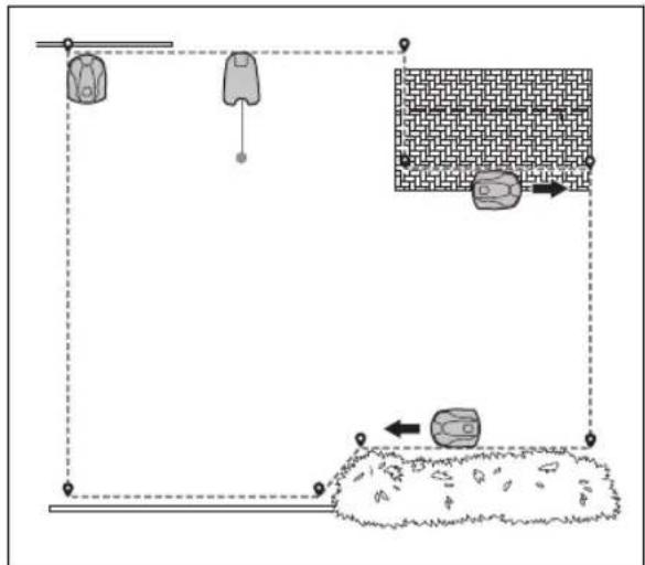
On the map you can install the objects that follow in the app:
Work areas(A)
Stay-out zones(B)
Transport path (C)
Charging station(D)
- Maintenance point (E)
Reference station(F)
Work area (Secondary area) (G)
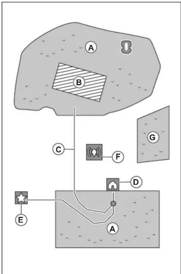
For a complete map installation, you must install a work area and a charging station on the map.
A work area is specified by virtual boundaries. Maximum work areas and secondary areas can be installed on a map.
There are two types of work areas:
- A work area that has a charging station in it or connected to it with a transport path where the product operates automatically.
- A secondary area is a work area with no charging station and no transport path. The product must be moved manually to and from the work area.
A transport path is a specified path between the docking point in front of the charging station and a work area. The product can operate automatically in this path, but does not cut grass. A transport path can temporarily be enabled and disabled in the app.
Stay-out zones can be made if there are areas where the product must not operate. A stay-out zone is specified by virtual boundaries. Stay-out zones can temporarily be enabled and disabled in the app.
A maintenance point is a specified position where the product can be parked at. This can for example be used for a service point where maintenance of the product is done. The maintenance point is connected to the docking point with a path.
To install objects on the map, operate the product with the appDrive installation to add waypoints on the map. Refer to To install objects on the map on page 16.
3.10.6.1 To install objects on the map
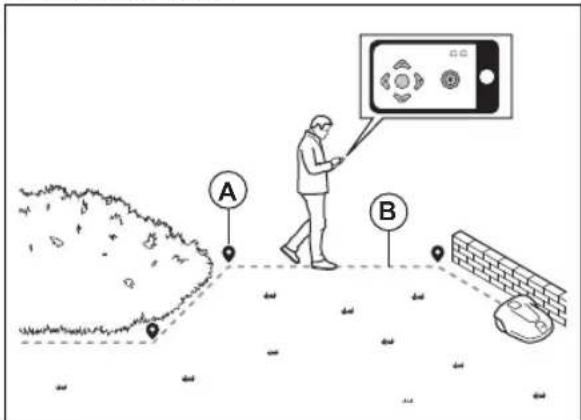
The waypoints (A) are positions that makes the virtual boundaries and paths (B). The lines are straight between the waypoints. It is recommended to use as few waypoints as possible. For each work area and the related stay-out zones and transport path the total maximum number of waypoints are 800. Husqvarna recommends to add maximum 1000 waypoints for the complete installation of the map. You can adjust the positions of the waypoints in the app after the installation of the map. To make smooth curves use several waypoints. Husqvarna recommends to set the minimum distance of 30~cm / 1 ft. between the waypoints. You can adjust the positions of the waypoints in the app after the installation of the map.

CAUTION: Do not lift and move the product between the waypoints when you install the map objects. Use appDrive for a correct installation.
Note: The position of the waypoint when you install a work area or a stay-out zone is in the front left corner of the product. The work area is specified by the virtual boundaries. The product cannot cut all the grass in the work area because of the position of the cutting disc.
Note: The position of the waypoint when you install a transport path or a path to a maintenance point is in the middle of the product between the drive wheels.
- Make sure that you are near the product and connected to the product with the app with Bluetooth®.
Make sure that the status is EPOSTM confirmed in the appDrive.
Note: A game controller with Bluetooth® can be used together with appDrive to operate the product.
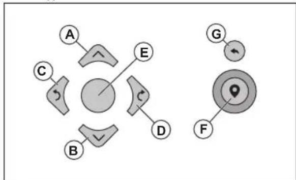
- Select the object you want to install and use the buttons in the appDrive installation to operate the product.
- Use the up button (A) to move the product forward.
- Use the down button (B) to move the product rearward.
- Use the left arrow button (C) to rotate the product to the left.
- Use the right arrow button (D) to rotate the product to the right.
- Use the center button (E) as a joystick to move and rotate the product in any direction.
- Use the waypoint button (F) to add a waypoint in the map.
- Use the undo button (G) to remove the latest waypoint.
Note: Walk 2-3 m / 6.5-9.8 ft. behind the product when you operate the product with appDrive.
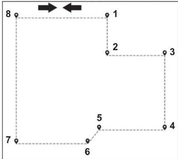
To make a work area
Minimum 3 waypoints are necessary to make a work area.
- Operate the product clockwise around the boundary of the work area.
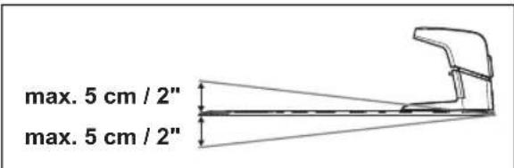
- Add waypoints on the map. Add the waypoints minimum 3 cm / 1 in. from obstacles.
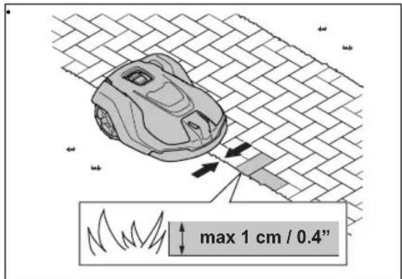
- Add a waypoint to make the product cut the grass at the edge between the lawn and the stone path. Make sure that you straddel the edge of the lawn and the stone path when you add a waypoint. The product can straddel the edge if the height of the stone path is maximum 1 cm / 0.4 in. in relation to the lawn.
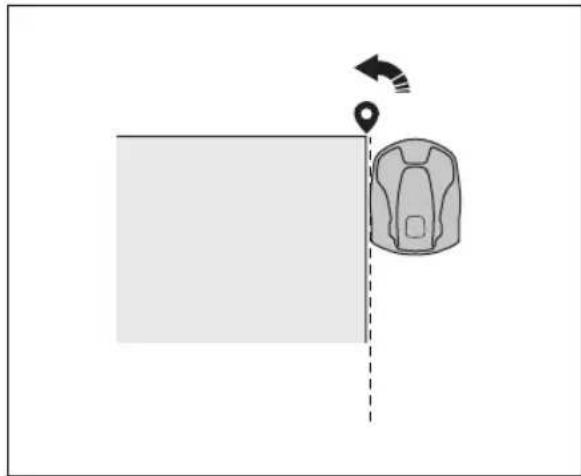
- Add the waypoint at the outer corner to install the virtual boundary around a corner.
- Do not set waypoints that make a virtual boundary go across itself in the same work area.
- Save the work area to automatically connect the first and last waypoint with a virtual boundary.
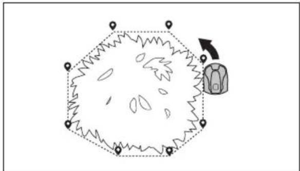
To make a stay-out zone
Minimum 3 waypoints are necessary to make a stay-out zone.
- Operate the product counterclockwise around the boundary of the stay-out zone.
- Add waypoints on the map. Add the waypoints minimum 3 cm / 1 in. from obstacles.
- Do not set waypoints that make a virtual boundary go across itself in the same stay-out zone.
- Save the stay-out zone to automatically connect the first and last waypoint with a virtual boundary.
To make a transport path
- Operate the product and add waypoints on the map to install a transport path. Start in a work area minimum 1m / 3.3 ft. from the virtual boundary.
- Install the transport path perpendicular to the virtual boundary of the work area.
- Do not install a transport path across a stay-out zone.
- Do not set waypoints that make the transport path go across the same transport path.
- Do not make sharp bends when you install the transport part.
- Operate the product and add waypoints to connect the transport path to the docking point.
- Put the last waypoint on a transport path (A) in an angle of +/-45 degrees seen from the docking point.

- Save the transport path to automatically connect the last waypoint to the docking point.
- Set the corridor width (A) for the transport path. The corridor width can be set to 2-5 m / 6.6-16.4 ft.
To make a maintenance point
- Operate the product and add waypoints on the map. Start to add waypoints at the position where you install the maintenance point. The first waypoint specifies the maintenance point.
- Do not make sharp bends when you install a transport part.
- Operate the product and add waypoints to make a path to the charging station.
- Put the last waypoint on a transport path (A) in an angle of +/-45 degrees seen from the docking point.
- Save the maintenance point to automatically connect the last waypoint to the docking point.
- Set the corridor width (A) for the maintenance point. The corridor width can be set to 2-5 m / 6.6-16.4 ft.
To reinstall the charging station on the map
Reinstall the charging station on the map if you move or replace the charging station. You can also reinstall it if the robotic lawn mower cannot dock or connect to the charging station.
- Select map objects > Charging station in the app.
- Select Reinstall charging station and follow the instructions.
To reinstall the reference station on the map
Reinstall the reference station on the map if you move or replace the reference station.
- Select Map objects > Reference station in the app.
- Select Reinstall reference station and follow the instructions.
4 Maintenance
4.1 To clean the reference station
Husqvarna recommends to use a special cleaning and maintenance kit, available as an accessory. Speak to your Husqvarna representative for more information.

CAUTION: Do not use a high-pressure washer to clean the product and the charging station. Do not use solvents for cleaning.
4.2 To clean the EPOS™ Plug-in

CAUTION: Do not use a high-pressure washer or running water to clean the product.
If necessary, use a moist cloth to clean the product.
If necessary, use a moist cloth to clean the product.
5 Troubleshooting
5.1 Introduction - troubleshooting
You can find all the troubleshooting messages in the Messages menu in Automower Connect. You can find more information on www.husqvarna.com.
5.2 Fault messages
The fault messages in the table below are shown in the Automower Connect app. Speak to your Husqvarna representative if the same message shows frequently.
| Message Cause Action | ||
| No loop signal | The power supply or the low-voltage cable for the charging station is not connected. | If the LED indicator on the charging station is out, it shows that there is no power. Examine the power outlet connection and the residual-current device. Make sure that the low-voltage cable is connected to the charging station. |
| The power supply or the low-voltage cable for the charging station is damaged. | Replace the power supply or low-voltage cable. | |
| ECO mode is enabled and the LED indicator of the charging station flashes green. The product was started manually in the work area but the STOP button was not pushed before the product was moved from the charging station. The charging station signal is disabled and the product cannot enter the charging station. | Put the product in the charging station. Start the product. | |
| The product does not find the loop signal from the charging station. | Put the product in the charging station and make a new loop signal. | |
| The charging station in not installed correctly. | Install the charging station according to the instruction. Refer to To install the charging station on page 12. | |
| Interference from metal objects such as fences, reinforcement steel or buried cables near the charging station. | Change the position of the charging station. | |
| Outside work area | The work area slopes too much by the virtual boundary. | Make sure that the virtual boundary is installed correctly. |
| The transport path or the path to the maintenance point slopes too much. | Make sure that the transport path is installed correctly. Refer to To make a transport path on page 18. | |
| The product can not find the correct charging station signal because of interference with a loop signal from a different product installation nearby. | Put the product in the charging station and make a new loop signal. | |
| Interference from metal objects such as fences, reinforcement steel or buried cables near the charging station. | Change the position of the charging station. | |
| Empty battery | The product cannot find the charging station. | The product has no accurate position and cannot find the charging station. |
| There is an obstacle that prevents the product to find the charging station. | ||
| The battery is at the end of its life cycle. Replace the battery. | ||
| The antenna of the charging station is defective. | If the LED indicator on the charging station flashes red, the antenna of the charging station is defective. Speak to your approved servicing dealer. | |
| Map problem | There is no specified work area. Make a work area in the Automower Connect app. Refer to To make a work area on page 17. | |
| The map object file is incorrect. Do a check of the map in the app. Adjust the map and save it. | ||
| Searching for position | Weak satellite signal to the reference station. | The satellite signal is temporary weak. The product will start to operate when the satellite signals are good. |
| Examine the installation of the reference station.. | ||
| Weak satellite signal to the product. The satellite signal is temporary weak. The product will start to operate when the satellite signal are good. | ||
| Boundary wire problem | The boundary wire is damaged or not installed correctly. | Examine that the boundary wire is connected correctly to the charging station. Examine all splices on the boundary wire. Examine if the boundary wire is damaged and repair it if it is necessary. |
| Reference station communication problem | The product is not connected to the reference station. | Do a pairing operation between the product and the reference station. |
| The reference station is not installed correctly. | Examine the installation of the reference station. | |
| The product does not receive the radio signal from the reference station in all areas where the product operates. | Test if the product has radio signal from the reference station in all of the work area. If not, make a new installation of the reference station or a new installation of the map. Refer to To install objects on the map on page 16. | |
| Power failure. Examine and correct the cause | use for the power failure of the reference station. | |
| There is an error in the reference station and the LED indicator flashes red. | Disconnect the power to the reference station and connect it again to restart the reference station. If the problem stays, speak to your approved servicing dealer. | |
| There is interference with another reference station or other radio systems in the area. | Restart the product. If the problem stays, speak to your approved servicing dealer. | |
| Too many waypoints | There are too many waypoints in the current work area. | Do a new installation of the work area, stay-out zone and transport paths. Make less waypoints. Divide the current work area into more work areas. |
| Destination not reachable | There is no transport path between the charging station and the work area or maintenance point. | Make a transport path between the charging station and the work area or maintenance point. |
| The transport path is blocked and the product cannot go to the work area, charging station or maintenance point. | Make sure that the transport path is not blocked, or delete the transport path and make a new transport path. | |
| Multiple reference stations | There is more than one reference station near the work area. This can cause interference for the product from a different reference station. | Speak to your approved servicing dealer if the same problem occurs frequently. |
| EPOS plug-in not found | The EPOSTM Plug-in is defect or not installed correctly. | Restart the product. Make sure that the EPOSTM Plug-in is installed correctly and that the cable is connected. If the problem stays, speak to your approved servicing dealer. |
| Work area tampered | The charging station or the reference station was moved. | Do a new installation of the map. |
| Accessory power problem | There is a power problem with the accessory port. | Set the product to OFF and disconnect and reconnect the accessory to the accessory port. Restart the product. If the problem stays, speak to your approved servicing dealer. |
5.3 LED indicator lamp on the reference station
| Light Status | |
| Green flashing light Startup | of the reference station. Wait some minutes. |
| Green constant light In operation. | |
| Red flashing light The reference station does not operate because of an error. Disconnect the power cord and connect it again to restart the product. If the problem stays, speak to your approved servicing dealer. | |
| White flashing light Firmware | update is necessary. Speak to your local Husqvarna representative. |
| Yellow flashing light Only for | reference station in repeater mode: The reference station in repeater mode has no connection to the main reference station. The reference station is in startup mode or has no connection to the main reference station. If there is no connection, examine the main reference station or the nearest repeater. |
5.4 LED indicator lamp on the charging station
For a fully functional installation, the indicator lamp in the charging station must show a solid or flashing green light. If another color shows, follow the troubleshooting guide below.
There is more help on www.husqvarna.com. If you still need help, speak to your local Husqvarna representative.
| Light | Status |
| Green solid light Good signals | |
| Green flashing light The signals are good and ECO mode is activated. | |
| Blue flashing light The boundary wire is damaged. | |
| Red flashing light Interruption in the charging station's antenna. Speak to your local Husqvarna representative. | |
| Red solid light Fault in the circuit board or incorrect power supply in the charging station. The fault must be correct by an authorized service technician. Speak to your local Husqvarna representative. | |
6 Storage and disposal
6.1 Storage
If you store the reference station indoors, keep the arm installed at the post or wall to be able to install the reference station on its original position again.
If you keep the reference station outdoors during the winter, we recommend you to keep the power supply connected.
6.2 Disposal
Obey the local recycling requirements and applicable regulations.
7 Technical data
7.1 Technical data
| Reference station EPOS™ RS1 dimensions | ||
| Length, cm/in. 17/6.7 | ||
| Width, cm/in. 16/6.3 | ||
| Height, cm/in. 22/8.7 | ||
| Weight, kg/lb 0.5/1.1 | ||
| Reference station EPOS™ RS1 product data | ||
| Type of Power Supply Unit FW7313/28/D/XX/Y/1.3 | ||
| Power supply input, V AC 100-240 | ||
| Power supply output, V DC 28 | ||
| Power supply output, A 1.3 | ||
| Low-voltage cable, length m/ft 20 / 66 | ||
| IP-code reference station IPX5 | ||
| IP-code power supply unit IP44 | ||
| Power consumption, W 2.8 | ||
| EPOS™ Plug-in product data | ||
| Input voltage, V DC 18 | ||
| Power consumption, W 1.8 | ||
| IP code IPX5 | ||
| Reference station EPOS™ RS1 Frequency Band Support | ||
| Bluetooth® Frequency range (for service) 2400.0-2483.5 MHz | ||
| SRD868 863-870 MHz | ||
| Reference station EPOS™ RS1 Power Class | ||
| Bluetooth® Output power (for service) 8 dBm | ||
| SRD868 13 dBm | ||
Full compatibility cannot be guaranteed between the product and other types of wireless systems such as remote controls and radio transmitters.
7.2 Registered trademarks
The Bluetooth® word mark and logos are registered trademarks owned by Bluetooth SIG, inc. and any use of such marks by Husqvarna is under license.
8 Declaration of Conformity
For Declaration of Conformity, refer to the Operator's manual supplied with the robotic lawn mower.
Innehäll
9 Sakerhet. 26
10 Introduktion. 27
11 Installation 30
12 Underhäll 43
35.3 Klargjering for installations

OBS: Vann i dumper pa plenen kan fore til skade pa robotklipperen.

OBS: Les installasjonskapitlet f#r du starter installeringen.
AUTOMOVER® is a trademark owned by Husqvarna AB.
Copyright © 2023 HUSQVARNA. All rights reserved.
www.husqvarna.com
Original instructions Bruksanvising i original Originale instruktioner Alkuperaiset ojeet
Originale instruksjoner Instructions d'origine
Originele instructies Istruzioni originali Instrucciones originales Originalanweisungen Instruções originais Izvirna navodila