
YT-84860 - Cultivator Yato - Free user manual and instructions
Find the device manual for free YT-84860 Yato in PDF.

| Product type | Cultivator (gasoline tiller) |
| Brand | Yato |
| Model | YT-84860 |
| Weight | 36 kg |
| Fuel tank capacity | 1.5 L |
| Oil tank capacity | 0.6 L |
| Working width (furrow) | 600 mm |
| Maximum working depth | 170 mm |
| Blade diameter | 270 mm |
| Engine | TB1P70FA, 4-stroke, single cylinder, air-cooled |
| Engine displacement | 173 cm³ |
| Engine power | 3.6 kW |
| Maximum engine speed | 3000 min⁻¹ |
| Fuel consumption | 1.6 L/h |
| Spark plug type | F7RTC |
| Sound pressure (LpA) | 77.9 dB(A) |
| Sound power (LWA) | 92.58 dB(A) |
| Vibration level (right/left handle) | 3.10 m/s² / 3.02 m/s² |
| Recommended fuel | Unleaded gasoline with octane rating ≥ 95 |
| Recommended engine oil | SAE 15W40 for 4-stroke engine |
| Oil change interval | Every 25 hours |
| Blade replacement interval | Every 2 years or 50 hours |
| Safety equipment | Blade guards, emergency stop, drive lever lock |
| Included accessories | Auxiliary wheels, depth regulator |
Frequently Asked Questions - YT-84860 Yato
User questions about YT-84860 Yato
0 question about this device. Answer the ones you know or ask your own.
Ask a new question about this device
Download the instructions for your Cultivator in PDF format for free! Find your manual YT-84860 - Yato and take your electronic device back in hand. On this page are published all the documents necessary for the use of your device. YT-84860 by Yato.
USER MANUAL YT-84860 Yato
natural_image
Mechanical assembly diagram showing a motor with labeled parts (no text or symbols present)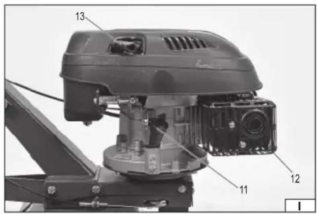
natural_image
Close-up of a hand operating a manual drive mechanism with a wheel and mechanical component (no visible text or symbols)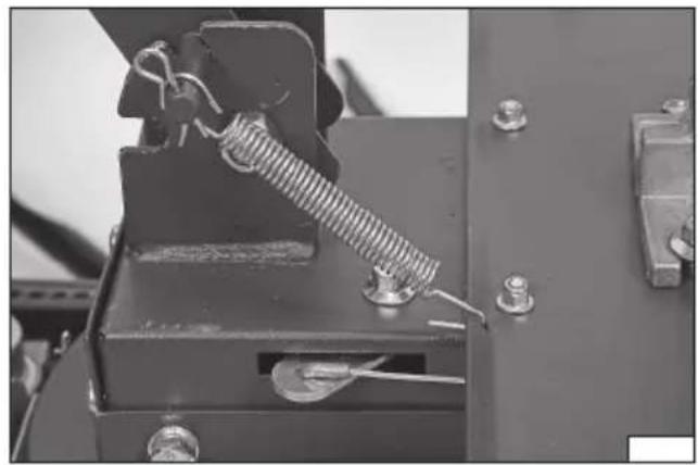
natural_image
Close-up of a mechanical clamp or spring assembly with bolts and metal components (no visible text or symbols)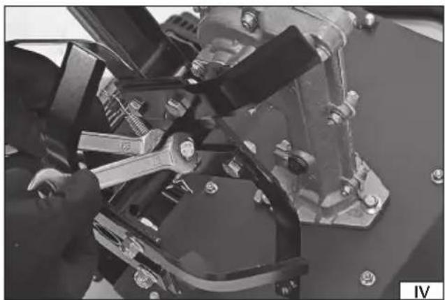
natural_image
Close-up of mechanical components with no visible text or symbols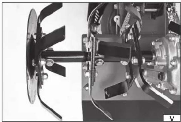
natural_image
Mechanical assembly diagram showing a motor drive and housing components (no visible text or labels)natural_image
Close-up of a metal tool with a handle and circular holes, mounted on a wire (no visible text or symbols)
natural_image
Close-up of a hand holding a wrench on a metal workbench (no visible text or symbols)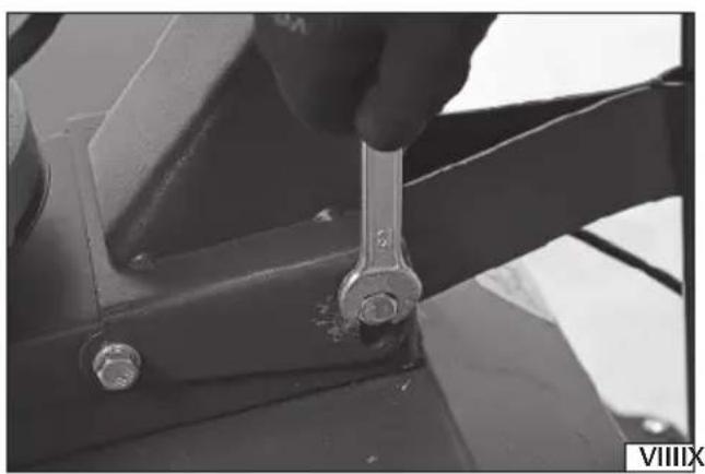
natural_image
Close-up of a hand using a wrench to adjust a metal bracket component (no visible text or symbols)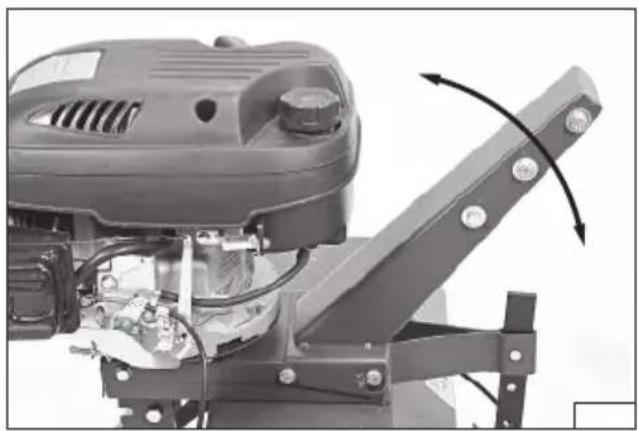
natural_image
Close-up of a mechanical powertrain with visible blades and components, no text or symbols present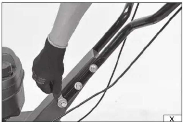
natural_image
Close-up of a hand using a black mechanical linkage with wires, no visible text or symbols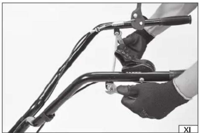
natural_image
Close-up of a hand holding a bicycle handle with metal bands and a small tool, no visible text or symbols
natural_image
Close-up of a bicycle handle mechanism with a hand adjusting the lever (no visible text or symbols)
natural_image
Close-up of two hands holding a tool, one with a screwdriver and the other with a circular opening (no visible text or symbols)PL DE RU UA LT LV CZ SK HU RO ES FR IT NL GR

natural_image
Close-up of a manual lawn mower with attached filter and power supply (no visible text or symbols)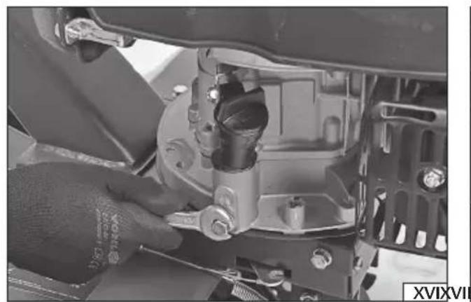
natural_image
Close-up of a mechanical assembly with a hand adjusting a component (no visible text or symbols)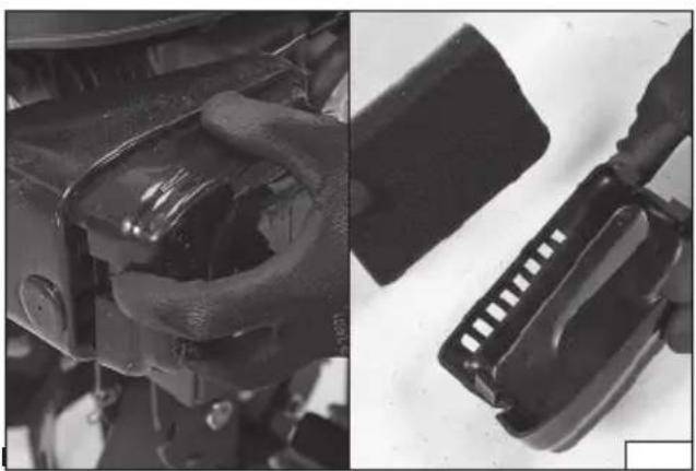
natural_image
Close-up of mechanical components and a close-up of a black plastic connector (no visible text or symbols)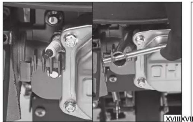
natural_image
Close-up mechanical assembly showing two views of a vehicle's internal components (no visible text or symbols)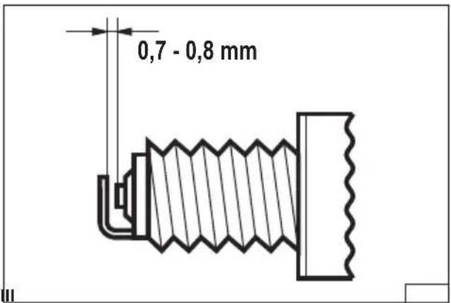

flowchart
graph TD
    A["Top Path"] --> B["Left Path"]
    B --> C["Right Path"]
    C --> D["Bottom Path"]
    D --> E["Left Path"]
    E --> F["Right Path"]
    F --> G["Bottom Path"]
    G --> H["Left Path"]
    H --> I["Right Path"]
    I --> J["Bottom Path"]
PL DE RU UA LT LV CZ SK HU RO ES FR IT NL GR
PL
-
engine
-
handle
-
throttle lever
-
blades' drive lever
-
fuel filler cap
-
blades
-
blades' guard
-
auxiliary wheel
-
air fi lter
-
spark plug
-
oil fi ller
-
silencer and exhaust pipe
-
starter pull cord
DE
Read the operating instruction
Wear protective goggles
Schutzbrille tragen
Wear hearing protectors
Wear protective shoes
Keep away from rotating parts.
Stay away from bystanders
Beware of the discarded items
Switch off the tool and unplug the spark plug cable before assembly, adjustment and maintenance
PRODUCT CHARACTERISTICS
The engine-powered rototiller is designed for opening and cultivating small patches of soil. It makes cultivating land in gardens and plots significantly easier. Soil cultivation is carried out using rotating blades. It is unacceptable to use the rototiller for cultivating larger patches of land. Proper, reliable and safe operation of the tool depends on appropriate use, that is why you should
Read this entire instructions manual before the first use of the tool and keep it for future reference.
The supplier shall not be held liable for any damage or injury resulting from improper use of the tool, failure to observe the safety regulations and recommendations of this manual. Use of the tool for purposes other than those for which it was intended shall cause the loss of the user's rights to a warranty and statutory warranty.
EQUIPMENT
The rototiller is supplied complete but requires assembly before first use.
TECHNICAL DATA
| Parameter Unit Value | ||
| Catalogue No. YT-84860 | ||
| Weight | [kg] | 36 |
| Fuel tank capacity [l] 1.5 | ||
| Oil tank capacity [l] 0.6 | ||
| Groove width [mm] 600 | ||
| Max. groove depth [mm] 170 | ||
| Blade diameter [mm] 270 | ||
| Engine TB1P70FA | ||
| number of cylinders | 1 | |
| number of strokes | 4 | |
| cooling Air cooling | ||
| Spark plug type | F7RTC | |
| Engine displacement | [cm3] 173 | |
| Engine power [kW] | 3.6 | |
| Maximum engine rotary speed | [min-1] | 3000 |
| Fuel consumption | [l/h] | 1.6 |
| Noise | ||
| sound pressure | [dB (A)] | 77.9 ± 0.199 |
| power LWA | [dB (A)] | 92.58 ± 0.199 |
| Vibration level - right/left handle | [m/s] | 3.10 ± 1.5 / 3.02 ± 1.5 |
SAFETY INSTRUCTIONS
IMPORTANT! READ CAREFULLY BEFORE USE KEEP FOR FUTURE REFERENCE
Manual
Read the instructions carefully. Familiarise yourself with the controls and proper use of the tool. If you are going to pass the tool on to another person, always attach the manual to the tool. Always use the tool in accordance with the guidelines in the manual. Never allow children or persons who have not read the manual to operate the tool. National regulations may specify the exact age of the operator.
Never work when anyone else, especially children or pets, is around. Before starting work, designate a safety zone within which bystanders and pets will not be allowed.
Remember that it is the operator or the user who is responsible for accidents or hazards to other people or the environment.
Preparation
Always wear sturdy shoes and long trousers when working. Do not operate the tool barefoot or when wearing open toe sandals. Avoid wearing damaged clothing which is too loose or has hanging straps or ribbons. Loose clothing parts can be caught by the tool's moving parts which can lead to injuries.
Carefully check the area where the tool will be operated and remove any objects which could get into the tool. Caught objects can cause damage to the tool, or can be ejected at high speed, which poses a threat to the operator and the environment.
EN
WARNING — Petrol is fl ammable:
- store fuel in containers designed for this purpose,
- refuel only outdoors and do not smoke during refuelling,
- refuel before starting the engine; never remove the fuel tank cover or add fuel if the engine is running or hot,
- if petrol is spilled, do not try to start the engine, just move the machine away from the spill area and avoid creating any sources of ignition until the petrol vapours dissipate,
- safely replace the fuel tank and the tank cover.
Replace damaged silencer. Working with a damaged silencer is not only noisier, but can cause fire, burns and exhaust gas poisoning.
Always check the blades, bolts and the blades' assembly equipment for wear or damage before use. Replace worn-out or damaged parts in sets to maintain balance. Replace damaged or illegible plates.
Operation
Do not use the engine in a confined space where vapours of dangerous carbon monoxide may accumulate.
Work only in daylight or in good artificial lighting. Improper lighting of the workplace can lead to accidents.
When on a slope, always make sure your feet are set firmly.
Walk, never run.
Work across the slopes, never up or down. This will make control of the tool much easier.
Take special care when changing driving direction on a slope.
Do not work on excessively inclined slopes.
Pay special attention when reversing or pulling the tool towards you.
Do not change the settings of the engine regulator and do not exceed the maximum engine speed.
Turn off the drive of the cutting element(s) if the tool must be tilted when moving it on surfaces other than the workplace and when transported to and from the workplace.
Do not use the tool with damaged guards or housings and without a safety device, e.g. attached guards.
Switch on the engine carefully in accordance with the instructions, paying attention to whether your feet are away from the cutting element.
Do not tilt the tool when starting the engine, except when it requires tilting during starting. In this case, do not tilt more than necessary and lift only the part which is away from the operator.
Keep your hands and feet away from rotating parts.
Do not move the tool with the engine running.
Stop the engine and make sure that all moving parts have stopped:
Stop the tool and make sure that all moving parts have stopped:
- every time you step away from the tool;
- before refuelling,
- before checking, cleaning or repairing the tool;
- after it being hit by a foreign object. Check that the tool is not damaged and, if necessary, repair it before restarting and operating. If the tool starts to vibrate excessively (check immediately):
- check for damage;
- replace or repair any damaged part;
- check and tighten any loose parts.
Maintenance and storage
Keep all nuts, bolts and screws in good condition to ensure safe tool operation.
Never store the tool with petrol in the tank inside the building where vapours can reach open flames or sparks.
Allow the engine to cool down before storage.
To reduce the risk of fire, keep the engine, silencer, battery compartment and fuel storage area free of plant material and excess grease. In the case of multi-blade tools, be careful, as rotation of one cutting element may cause rotation of other blades.
Use caution when adjusting the tool to avoid fingers getting between the tool's moving blades and fixed parts.
Always leave the tool to cool down before the next start-up, or before storing in a closed space.
Be careful when performing any work on the blades, even when the drive is switched off as the blades can still rotate. Always wait for the blades to come to a complete stop before proceeding with any activities.
Replace worn-out or damaged parts to ensure safety of operation. Use original spare parts and equipment only.
If the fuel has to be drained from the tank, this must be done outdoors.
Risks related to noise and vibrations
The tool is designed to reduce the risk of exposing the user to noise and vibration as much as possible. However, it is not possible to completely eliminate these hazards. Additionally, people in the vicinity of the operating tool are also exposed to noise hazards.
However, the risks associated with the above-mentioned hazards can be reduced by observing the following guidelines:
- the product should be used in accordance with its intended purpose, described in the manual;
- make sure that the tool is in good condition and is regularly maintained;
- use proper and well-sharpened cutting tools;
EN
- use a firm grip on the product handle;
- plan work so that frequent breaks can be incorporated.
Residual risks
Even if all safety precautions are followed during operation, the potential risk of injury remains. The following risks remain in relation to the design of the product.
Vibration-related injuries caused by prolonged operation of the tool, incorrect manner of work, or work with an improperly maintained tool.
Injuries caused by an unexpected impact from hidden, ejected objects.
PRODUCT OPERATION
Preparation for assembly
Unpack the product by removing all packaging components. It is recommended to retain the packaging, which can be of use when transporting or storing the product.
Check that no part of the product has been damaged during transport. In case of damage detection, such as cracks or deformations, it will disqualify the product from further use until it is repaired or damaged components are replaced.
It is recommended to place all the components on a flat, hard, and clean surface.
Use personal protective equipment such as protective gloves, eye protection, and protective clothing during assembly.
Tool assembly
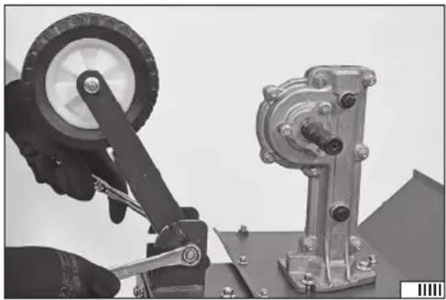
First of all, assemble the transport wheel. Fix the wheel bracket to the base with a bolt and nut (II). Attach spring hook on the bracket pin and secure using a locking pin. Attach the other end of the spring to the hole in the base (III). The spring protects the wheel against unintentional change of position. Leave the wheel in the bottom position while assembling the tool.
Apply a set of blades to the axle, and secure them to the axle with a bolt and nut (IV). Insert the axle of the additional set of blades into the axle of the already installed blades and secure with a bolt and nut (V). The blade must be mounted on both sides of the rototiller.
Slide the grooving depth adjuster into the hole at the back of the rototiller base and secure it with a pin and locking pin (VI). During the tool assembly, set the adjuster to the lowest position.
Install additional blade guards on both sides of the groove-maker using bolts (VII).
Attach the handle bracket to the base with bolts (VIII). The bracket allows for slight adjustment of inclination angle. To adjust, loosen all bolts slightly, adjust the angle of inclination and tighten all bolts. It is recommended to adjust the bracket angle of inclination after mounting the handle so that holding the tool can be as comfortable as possible.
Before installing the handle, set it in such a way that the cable covers are not tangled with each other. Fix each handle to the bracket using bolts (X). Connect the handles additionally with a rod, putting it through the holes near the handles and fixing it with nuts (XI).
The cable covers of both levers should be fixed to the handle with clips.
A correctly assembled rototiller should look like in the illustration (I).
Preparing for operation
Before starting work, replenish engine oil. In a factory state, there is only a small amount of oil in the engine to protect it during transport and storage. Prepare oil for four-stroke engines in viscosity class SAE 15W40.
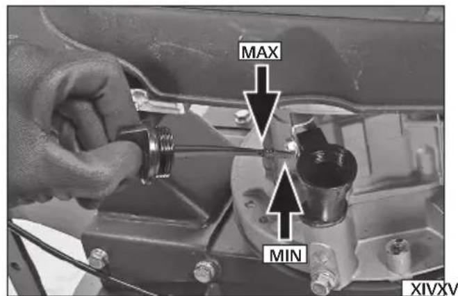
Before replenishing the oil, place the machine on a flat surface, then unscrew the oil tank cover and wipe the oil bayonet attached to it dry. Fill the tank with oil. When filling, it is recommended to use a funnel or filler nozzle to avoid spilling oil. In case of spilling the oil, thoroughly wipe off its residues before starting the engine. Check that the level is appropriate. To do this, insert the bayonet into the inlet and screw the tank cover. Then unscrew it and check the oil level on the bayonet. The oil level should be between the maximum and minimum levels on the bayonet (XIV). After making sure that the oil level is correct, close the inlet with a cap.
Caution! Check the oil level before each use.
After refilling oil, refill fuel. Use 95-octane unleaded petrol or better. To refuel, unscrew the oil tank cover and pour the fuel into the tank. When filling fuel, it is recommended to use a filler nozzle or funnel to reduce the risk of fuel splashes. If the fuel is splashed, thoroughly wipe off its residues. Wait until the vapours have completely evaporated and carry out the start-up at a different place than at which the fuel was filled. Close the fuel tank inlet with the cover after filling.
Preparing the workplace
The rototiller is intended only for soil cultivation. The soil cannot be too hard. If the soil is too hard or dry, moisturise it before starting work and wait for the water to soak into the soil.
Working on a hard surface such as concrete or wood is prohibited.
Before starting work, remove all visible stones, roots, wires and other items which may damage the rototiller blades. Particular attention should be paid to electrical cables, including those supplying power to the tool. Be aware that electrical cables can be hidden underground.
The rototiller only works correctly when it is driven forward. Avoid reversing the tool.
EN
Starting and stopping the tool
Set the rototiller in the place where the work is to commence. The rototiller can only be started when in vertical position.
If the rototiller is equipped with auxiliary wheels, they must be moved to an upper position. To do so, pull the wheel downwards so that the pin extends out of the slot, rotate the wheel with the bracket and make sure that the pin slides into the slot. A wheel attached in this manner will not automatically change its position.
Warning! You can only change the wheel position when the engine is off.
Set the grooving depth limiter to one of the available positions.
Warning! Change the position of the limiter only when the engine is off.
Make sure that the blades' drive lever is in the upper position. Only in this position will the blades not rotate immediately after starting the engine.
Push the throttle lever fully forward (XII) so that it is in the position marked with the throttle symbol. Hold the handle with one hand and the starter pull cord handle with the other hand and pull the rope vigorously (XV). After a few pulls, the engine should start. After starting the engine, set the throttle lever in the working position, between the rabbit symbol — faster rotation and the turtle — slower rotation. Moving the lever to the position marked O stops the engine.
Caution! If a warm engine is started, it can be started by turning the lever to one of the operating positions.
Grasp both handles, pull the blades' drive lever to the handle and hold it in this position. The lever is equipped with a lock that prevents it from being accidentally pressed. Switch the lock before pressing the lever (XIII). The lever cannot be locked in the bottom position. It should be held down at all times during work.
Warning! It is forbidden to lock the blades' drive lever in the bottom position. In this case, the blades will start when the engine is started, resulting in serious injury or even death.
Stop the tool following below steps: Stop in one place. Release the pressure on the blades' drive lever and allow it to return to the upper position. Check that the blades have stopped. Move the throttle lever to the position O; this will stop the engine.
Warning! The engine and exhaust system become hot during operation. Be careful not to get burned.
Move the transport wheel to the lower position and set the grooving depth limiter in the lowest position. By resting the machine on the wheel and lifting it so that the blades do not come into contact with the ground, transport the tool to the place of maintenance.
Rototiller operation
When working, you have to be prepared for unexpected situations. The blades may hit a stone, root or other obstacle which was not visible before. In such a case, turn the tool off immediately, allow it to cool down and inspect it. In case of any damage, do not proceed with work.
Do not exert excessive pressure on the rototiller. Blades should not sink in more than 3 to 4 centimetres.
Take regular breaks during work to avoid fatigue and overwork. This will allow better product control and reduce the risk of accidents.
Caution! Always push the rototiller while working; never pull it towards you. Pulling the tool causes the operator to move backwards, which means no control over the area behind the operator's back.
Push the rototiller slowly; always walk, never run. This will give you better control of the tool and reduce the response time to unexpected events.
During operation, move along the rows (XIX). Rows should be kept equal in width, slightly overlapping so as not to leave any space. Take special care when changing the direction.
Caution! If a foreign object hits the tool during operation, switch the tool off immediately, wait for the blades to stop and allow the tool to cool down. Then check the rototiller for damage. If the damage is detected, it is forbidden to continue working before removing the damage. Excessive vibration during operation can be caused by damage to the tool. Stop the operation, wait for the blades and engine to stop. Then wait for the tool to cool down and inspect the product.
PRODUCT MAINTENANCE
During the warranty period, the user cannot disassemble the tool or replace other assemblies or components than those listed below, as this will result in the loss of warranty rights. Any irregularities found during the inspection or the operation signal the need for repair to be done at the service centre.
Having finished your work, clean the housing, the vents, all switches, all handles and guards with compressed air (at 0.3 MPa maximum), a brush or a dry cloth. Do not use any chemicals or cleaners. Clean the tools and handles with a clean, dry cloth.
Scheduled inspections
Periodic inspection and maintenance of the following rototiller assemblies must be carried out.
CAUTION! All maintenance must be carried out with the tool switched off and not running. It is also necessary to disconnect all electrical equipment from the rototiller.
CAUTION! If a service operation is not described below, this means that the tool must be serviced by a specialist service centre for this purpose.
EN
CAUTION! Where solvent is used for cleaning, avoid contact of the solvent with skin and eyes. Use personal protective equipment.
General maintenance activities
The product cannot be cleaned with a water jet or by immersion in water.
Check for wear and damage to the blades. If excessive wear or damage is observed, replace the blade with a new one. The blades will lose the paint coating during operation. This is a normal phenomenon and does not indicate damage to the blades. Lack of paint coating, however, makes the blades more susceptible to corrosion. Therefore, each time after cleaning, they should be covered with a thin layer of anti-corrosion agent or a thin layer of light mechanical oil. Before starting work, the blades must be cleaned of any residual material to prevent the material from penetrating the soil.
Always replace the blades with the original ones, identical to the ones installed in the rototiller at the factory. Only the use of original spare parts can maintain the product safety. The blade should be replaced by an experienced user. To do this, contact an authorised service centre of the manufacturer.
The blades should be replaced every two years or after every 50 hours of operation.
If the power supply cord or the internal cable connecting the product power switch to the engine is damaged, it must be replaced by an authorised service centre of the manufacturer. The cables cannot be repaired and must be replaced. It is forbidden to operate the tool with any of the cables damaged.
Changing the engine oil (XVI) - every 25 hours of operation
Caution! It is best to change the engine oil as soon as the engine has come to a standstill. Then the oil is the thinnest and will flow out of the engine gearbox the fastest.
Care must be taken when changing the oil. As soon as the engine stops, the oil is hot and can cause burns. Each oil tank has a drain opening. Place a container with a capacity greater than that of the oil tank underneath the drain opening. Unscrew the drain valve completely using a wrench. Allow the oil to flow into the tank and then screw in the drain valve using a wrench. Wipe any oil residue dry.
Top up the oil according to the procedure described under "Preparing for operation".
Caution! Dispose of used engine oil in accordance with the local regulations. It is forbidden to spill engine oil into the sewer system.
Air fi Iter maintenance (XVII) - every 25 hours of operation
Caution! Do not operate the tool without a correctly installed air filter or with a defective air filter. Otherwise the combustion engine may aspirate impurities that would normally settle on the air filter. Impurities can lead to malfunctions or, ultimately, cause its failure.
Press the latch and open the air filter cover.
Soak the air filter sponge with clean engine oil and squeeze it out so that the filter remains slightly moist only.
Install the filter in place and fix the filter cover.
Spark plug maintenance (XVIII) - every 100 hours of operation
Disconnect the cable from the spark plug. Unscrew the spark plug with the spark plug wrench. Use a wire brush to clean carbon deposits off the electrodes (so-called combustion deposits). Check the distance between the electrodes, it should range between 0.7 mm and 0.8 mm.
If burned electrodes or the ceramic casing is broken, replace the spark plug with a new one.
Screw in the spark plug. Connect the cable to the spark plug.
STORAGE AND TRANSPORT
Caution! Always empty the fuel tank before storing or transporting the tool. Clean according to the instructions.
Store in the dark, dry, frost-free, and well-ventilated areas. The place of storage should protect the tool from access by children. The product should be stored at a temperature between 10 and 30°C. It is recommended that the product is stored in its original packaging or another packaging that protects it from dust. Store the tool in a vertical position.
Transport the product by carrying it by the handles. Transport it in such a position that the blades do not come into contact with the ground. Protect the product from impacts and strong vibrations during transport. Secure the product against slipping or tipping over during transport.
PRODUKTBESCHREIBUNG
CARACTÉRISTIQUES DU PRODUIT
WAARSCHUWING - Benzine is ontvlambaar:
SGS-CSTC Standard Technical Services (Shanghai) Co. Ltd.
588 West Jindu Road, Xinqiao, Songjian, 201612 Shanghai, China
DECLARATION OF CONFORMITY
0623/YT-84860/EC/2023
We declare and guarantee with full responsibility that the following products:
Gasoline tiller; 173 cm ^3 ; 3,6 kW; 600 mm; item no. YT-84860
meet requirements of the following European Standards / Technical Specifications:
EN 709:1997 + A4:2009
EN ISO 14982:2009
and fulfill requirements of the following European Directives:
2006/42/EC Machinery and safety elements
2014/30/EU Electromagnetic compatibility (EMC) Directive
2016/1628/EU Emissions from non-road mobile machinery
Serial number: concern all serials numbers of item(s) mentioned in this declaration
The last two digits of the year in which the CE marking was affixed: 21
Year of production: 2023
The person authorized to compile the technical file:
Tomasz Zych
(Place and date of issue)

(Name and signature of authorized person)
TOYA S.A.
DECLARATION OF CONFORMITY
0623/YT-84860/EC/2023
We declare and guarantee with full responsibility that the following products:
Gasoline tiller; 173 cm ^3 ; 3,6 kW; 600 mm; item no. YT-84860
fulfil requirements of the following European Directive: 2000/14/WE
Conformity assessment procedure:
Manufacturer quality-control system, examination of the manufacturer's technical file and periodical inspection by accredited body
Accredited body:
SGS-CSTC Standard Technical Services (Shanghai) Co. Ltd.
588 West Jindu Road, Xinqiao, Songjian, 201612 Shanghai, China
Measured sound power level on an equipment representative for this type: 92,58 dB(A)
Guaranteed sound power level for this equipment: 93 dB(A)
conformity and references of the other Community Directives applied:
2006/42/EC Machinery and safety elements
2014/30/EU Electromagnetic compatibility (EMC) Directive
2016/1628/EU Emissions from non-road mobile machinery
Wrocław, 2023.06.01
(Place and date of issue)

(Name and signature of authorized person)
TOYA S.A.