
DeskMeet X600 - Desktop computer ASROCK - Free user manual and instructions
Find the device manual for free DeskMeet X600 ASROCK in PDF.

| Product Type | Compact desktop computer (barebone) |
| Brand | ASRock |
| Model | DeskMeet X600 |
| Motherboard Form Factor | Deep mini-ITX |
| Supported Processor | AMD Socket AM5 Ryzen 7000 series (max 65W TDP) |
| Chipset | AMD X600 |
| Memory | 4 x DDR5, up to 192 GB, 7200+ (OC), dual channel |
| Expansion Slots | 1x PCIe 4.0 x16, 1x M.2 Key E for WiFi/BT |
| Storage | 1x Hyper M.2 Gen5 (2280), 1x Hyper M.2 Gen4 (2280), 2x SATA3 |
| Graphics | Integrated AMD RDNA 2 (depending on CPU), 1x HDMI 2.1, 2x DisplayPort 1.4, triple display |
| Audio | Realtek ALC897, HD Audio |
| Network | 2.5 Gigabit LAN (Dragon RTL8125BG) |
| Front I/O | 1x USB 3.2 Gen1 Type-C, 2x USB 3.2 Gen1 Type-A, 2x USB 2.0, 1x headphone jack |
| Rear I/O | 1x HDMI, 2x DisplayPort, 2x USB 3.2 Gen1, 2x USB 2.0, 1x RJ-45, audio jack, BIOS Flashback button |
| Required Power Supply | ATX 24-pin + 12V 8-pin connector (PSU not included) |
| Special Features | BIOS Flashback without CPU, chassis intrusion detection, memory overclocking, RAID 0/1/10 NVMe |
| Estimated Dimensions (W x D x H) | 168 x 208 x 258 mm |
| Estimated Weight | 3.5 kg |
| Operating System | Microsoft Windows 10 64-bit |
| Maintenance | Dust regularly with compressed air, avoid humidity and heat sources |
| Security | Chassis opening detection, secure BIOS Flashback, CMOS clear via jumper |
| Repairability | Accessible components (RAM, storage, motherboard), detailed documentation available |
| Certifications | FCC, CE, ErP/EuP Ready |
Frequently Asked Questions - DeskMeet X600 ASROCK
User questions about DeskMeet X600 ASROCK
0 question about this device. Answer the ones you know or ask your own.
Ask a new question about this device
Download the instructions for your Desktop computer in PDF format for free! Find your manual DeskMeet X600 - ASROCK and take your electronic device back in hand. On this page are published all the documents necessary for the use of your device. DeskMeet X600 by ASROCK.
USER MANUAL DeskMeet X600 ASROCK
Published December 2023

This device complies with Part 15 of the FCC Rules. Operation is subject to the following two conditions:
(1) this device may not cause harmful interference, and
(2) this device must accept any interference received, including interference that may cause undesired operation.
CALIFORNIA, USA ONLY
The Lithium battery adopted on this motherboard contains Perchlorate, a toxic substance controlled in Perchlorate Best Management Practices (BMP) regulations passed by the California Legislature. When you discard the Lithium battery in California, USA, please follow the related regulations in advance.
"Perchlorate Material-special handling may apply, see www.dtsc.ca.gov/hazardouswaste/perchlorate"

AUSTRALIA ONLY
Our goods come with guarantees that cannot be excluded under the Australian Consumer Law. You are entitled to a replacement or refund for a major failure and compensation for any other reasonably foreseeable loss or damage caused by our goods. You are also entitled to have the goods repaired or replaced if the goods fail to be of acceptable quality and the failure does not amount to a major failure.
The terms HDMI ^™ and HDMI High-Definition Multimedia Interface, and the HDMI logo are trademarks or registered trademarks of HDMI Licensing LLC in the United States and other countries.

HIGH-DEFINITION MULTIMEDIA INTERFACE
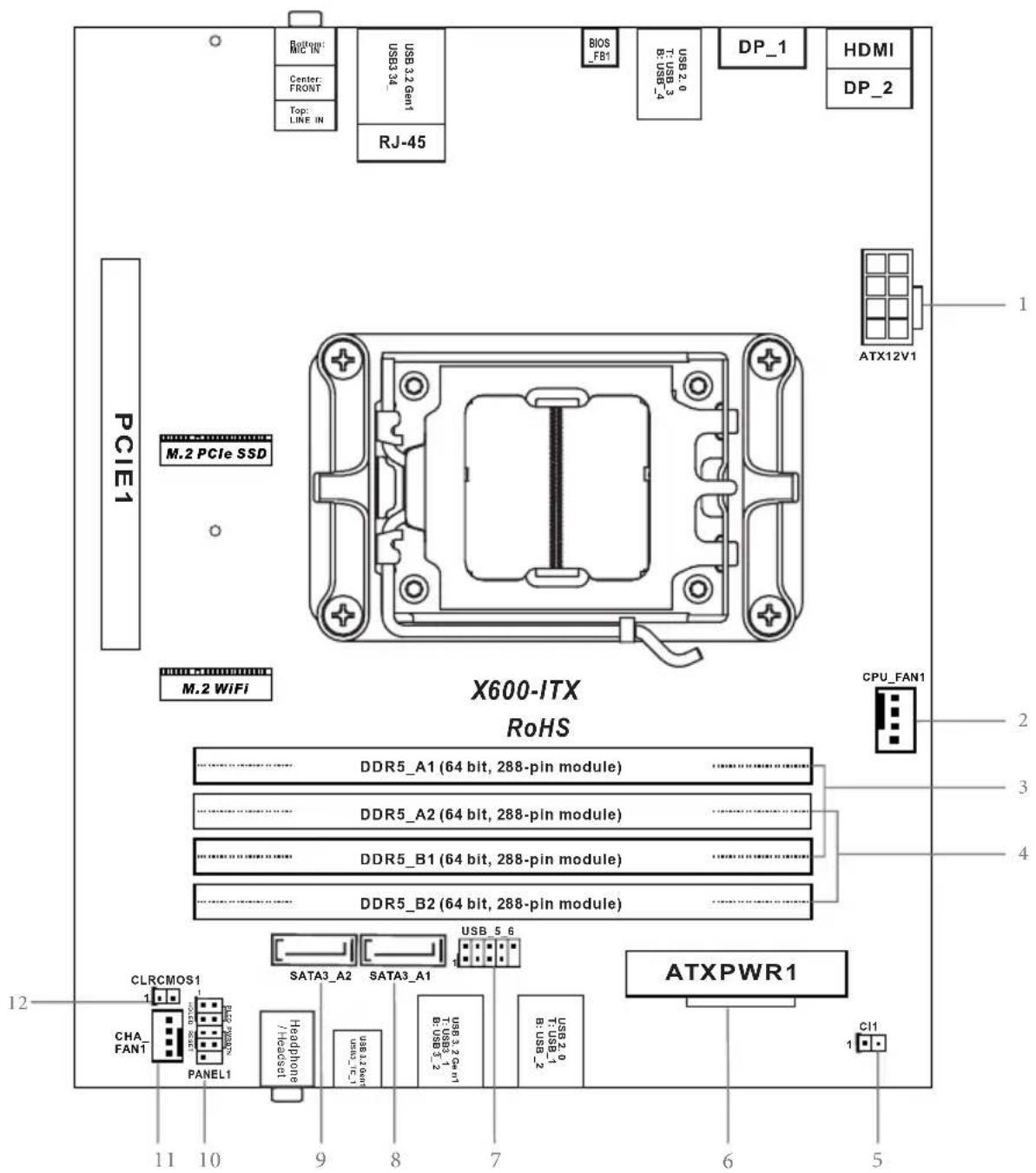
Motherboard Layout
Top Side View
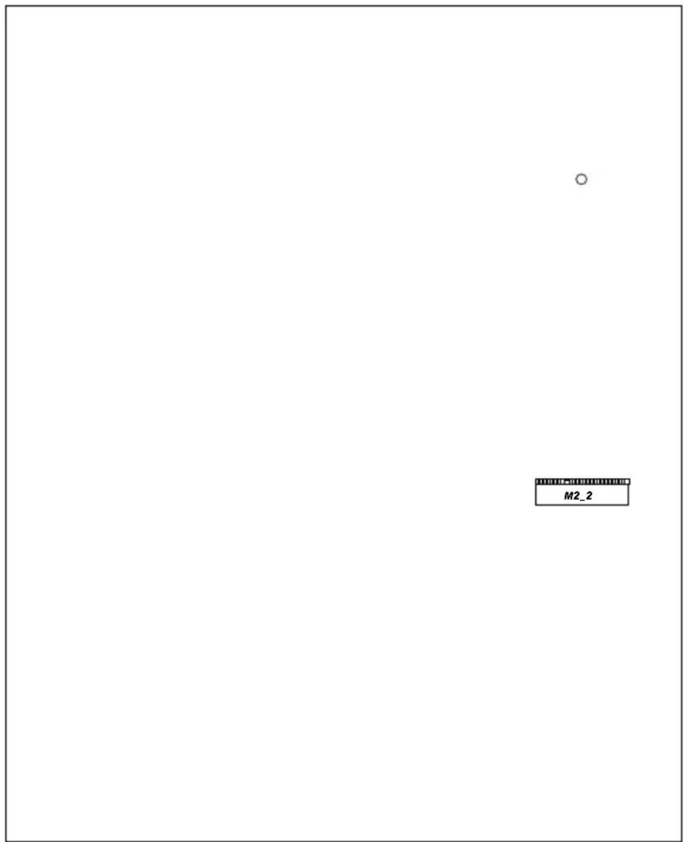
Back Side View
7
No. Description
1 8 pin 12V Power Connector (ATX12V1)
2 CPU Fan Connector (CPU_FAN1)
3 2 x 288-pin DDR5 DIMM Slots (DDR5_A1, DDR5_B1)
4 2 x 288-pin DDR5 DIMM Slots (DDR5_A2, DDR5_B2)
5 Chassis Intrusion Header (CI1)
6 ATX Power Connector (ATXPWR1)
7 USB 2.0 Header (USB_5_6)
8 SATA3 Connector (SATA3_A1)
9 SATA3 Connector (SATA3_A2)
10 System Panel Header (PANEL1)
11 Chassis Fan Connector (CHA_FAN1)
12 Clear CMOS Jumper (CLRCMOS1)
Front Panel
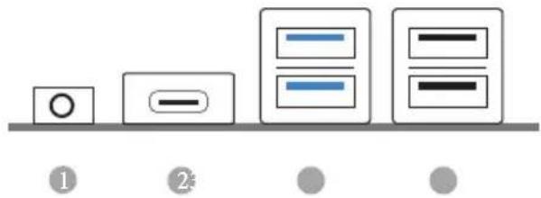
No. Description No. Description
1 Headphone/Headset Jack (AUDIO1)
3 USB 3.2 Gen1 Type-A Ports
2 USB 3.2 Gen1 Type-C Port (USB3_12)
(USB3_TC_1) 4 USB 2.0 Ports (USB_12)
Rear Panel
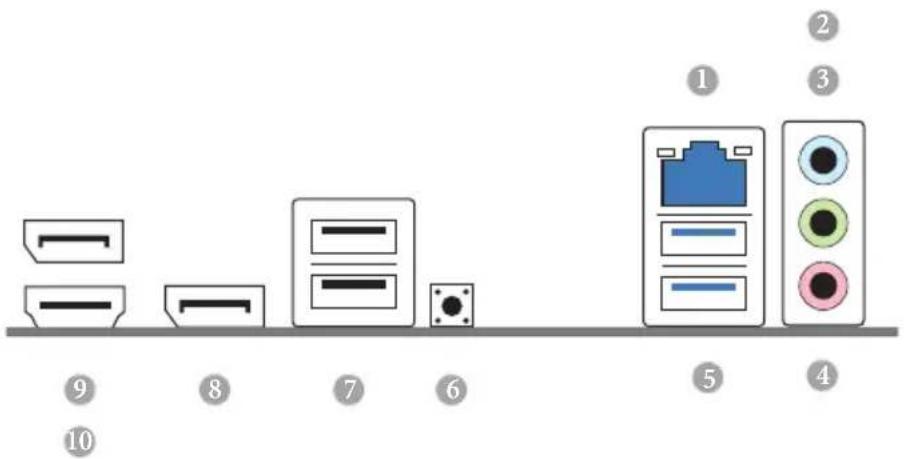
No. Description No. Description
1 2.5G LAN RJ-45 Port* 6 BIOS Flashback Button
2 Line In (Light Blue) ^ 7 USB 2.0 Ports (USB_34)
3 Front Speaker (Lime)** 8 DisplayPort 1.4 (DP_1)
4 Microphone (Pink) ^ 9 DisplayPort 1.4 (DP_2)
5 USB 3.2 Gen1 Ports (USB3_34) 10 HDMI Port
* There are two LEDs on each LAN port. Please refer to the table below for the LAN port LED indications.
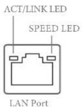
Activity / Link LED Speed LED
| Status | Description |
| Off | No Link |
| Blinking | Data Activity |
| On | Link |
| Status | Description |
| Off | 10Mbps connection |
| Orange | 100Mbps/1Gbps connection |
| Green | 2.5Gbps connection |
Chapter 1 Introduction
Thank you for purchasing X600-ITX motherboard. In this documentation, Chapter 1 and 2 contains the introduction of the motherboard and step-by-step installation guides.

Because the motherboard specifications and the BIOS software might be updated, the content of this documentation will be subject to change without notice.
1.1 Package Contents
• X600-ITX Motherboard (Deep mini-ITX Form Factor)
- 1 x I/O Panel Shield
• 2 x SATA Cables (Optional)
- 2 x Screws for M.2 Sockets (M2*2) (Optional)
• 1 x Screw for WiFi Module (M2*2) (Optional)
1.2 Specifications
| Platform | Deep mini-ITX Form FactorSolid Capacitor design |
| CPU | Supports AMD Socket AM5 RyzenTM 7000 Series ProcessorsSupports CPU up to 65W6+2 Power Phase design |
| Chipset | AMD X600 |
| Memory | Dual Channel DDR5 Memory Technology4 x DDR5 DIMM SlotsSupports DDR5 ECC/non-ECC, un-buffered memory up to 7200+(OC)*Max. capacity of system memory: 192GBSupports Extreme Memory Profile (XMP) and EXTended Profiles for Overclocking (EXPO) memory modules* Please refer to Memory Support List on ASRock's website for more information. (http://www.asrock.com/) |
| Expansion Slot | CPU:1 x PCIe 4.0 x16 Slot, supports x16 mode**Supports NVMe SSD as boot disks1 x M.2 Socket (Key E), supports type 2230 WiFi/BT module |
| Graphics | Integrated AMD RDNATM 2 graphics (Actual support may vary by CPU)Three graphics output options: 1x HDMI, 2 x DisplayPort 1.4Supports Triple Monitor1 x HDMI 2.1 TMDS/FRL 8G Compatible, supports HDR, HDCP 2.3 and max. resolution up to 4K 120Hz2 x DisplayPort 1.4 with DSC (compressed), support HDCP 2.3 and max. resolution up to 4K 120Hz |
Audio
• Realtek ALC897 Audio Codec
LAN
• 2.5 Gigabit LAN 10/100/1000/2500 Mb/s
- Dragon RTL8125BG
• Supports Dragon 2.5G LAN Software
- Smart Auto Adjust Bandwidth Control
- Visual User Friendly UI
- Visual Network Usage Statistics
- Optimized Default Setting for Game, Browser, and Streaming Modes
- User Customized Priority Control
Front
• 1 x Headphone/Headset Jack
Panel I/O
• 2 x USB 3.2 Gen1 Type-A Ports
• 1 x USB 3.2 Gen1 Type-C Port
- 2 x USB 2.0 Ports
Rear Panel
I/O
- 1 x HDMI Port
- 2 x DisplayPort 1.4
• 2 x USB 3.2 Gen1 Ports - 2 x USB 2.0 Ports
• 1 x RJ-45 LAN Port
• 1 x BIOS Flashback Button
• HD Audio Jacks: Line in / Front Speaker / Microphone
Storage
CPU:
- 1 x Blazing M.2 Socket (M2_1, Key M), supports type 2280 PCIe Gen5x4 (128 Gb/s) mode*
- 1 x Hyper M.2 Socket (M2_2, Key M), supports type 2280 PCIe Gen4x4 (64 Gb/s) mode*
ASMedia ASM1061:
• 2 x SATA3 6.0 Gb/s Connectors
* Supports NVMe SSD as boot disks
RAID
- Supports RAID 0, RAID 1 and RAID 10 for M.2 NVMe storage devices*
* Requires additional M.2 NVMe expansion cards to support RAID 10
Connector
• 1 x Chassis Intrusion Header
• 1 x CPU Fan Connector
* The CPU Fan Connector supports the CPU fan of maximum 1A (12W) fan power.
• 1 x Chassis Fan Connector (4-pin)
* The Chassis Fan Connector supports the chassis fan of maximum 1A (12W) fan power.
• 1 x 24 pin ATX Power Connector
• 1 x 8 pin 12V Power Connector
• 1 x Front Panel Header
• 1 x USB 2.0 Header (Supports 2 USB 2.0 ports)
BIOS
• AMI UEFI Legal BIOS with GUI support
Feature
Hardware
• CPU, Chassis Temperature Sensing
• CPU, Chassis Fan Tachometer
- CPU, Chassis Quiet Fan (Auto adjust chassis fan speed by CPU temperature)
• CPU, Chassis Fan Multi-Speed Control
• CASE OPEN detection
• Voltage monitoring: +12V, +5V, +3.3V, CPU Vcore
os
- Microsoft® Windows® 10 64-bit
Certifica-
- FCC, CE
tions
- ErP/EuP ready (ErP/EuP ready power supply is required)

Please realize that there is a certain risk involved with overclocking, including adjusting the setting in the BIOS, applying Untied Overclocking Technology, or using third-party overclocking tools. Overclocking may affect your system's stability, or even cause damage to the components and devices of your system. It should be done at your own risk and expense. We are not responsible for possible damage caused by overclocking.
Chapter 2 Installation
This is a Deep mini-ITX form factor motherboard. Before you install the motherboard, study the configuration of your chassis to ensure that the motherboard fits into it.
Pre-installation Precautions
Take note of the following precautions before you install motherboard components or change any motherboard settings.
- Make sure to unplug the power cord before installing or removing the motherboard. Failure to do so may cause physical injuries to you and damages to motherboard components.
- In order to avoid damage from static electricity to the motherboard's components, NEVER place your motherboard directly on a carpet. Also remember to use a grounded wrist strap or touch a safety grounded object before you handle the components.
- Hold components by the edges and do not touch the ICs.
- Whenever you uninstall any components, place them on a grounded anti-static pad or in the bag that comes with the components.
- When placing screws to secure the motherboard to the chassis, please do not over-tighten the screws! Doing so may damage the motherboard.
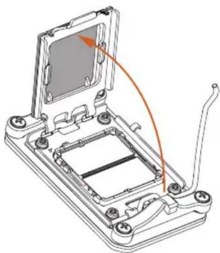
2.1 Installing the CPU

- Before you insert the 1718-Pin CPU into the socket, please check if the PnP cap is on the socket, if the CPU surface is unclean, or if there are any bent pins in the socket. Do not force to insert the CPU into the socket if above situation is found. Otherwise, the CPU will be seriously damaged.
- Unplug all power cables before installing the CPU.

Tutorial Video
natural_image
Technical line drawing of a mechanical component with mounting holes and a central square feature (no text or symbols)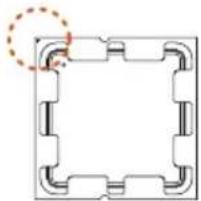
natural_image
Pure geometric diagram of a square frame with internal cutouts and a dashed circle highlighting one corner (no text or symbols)
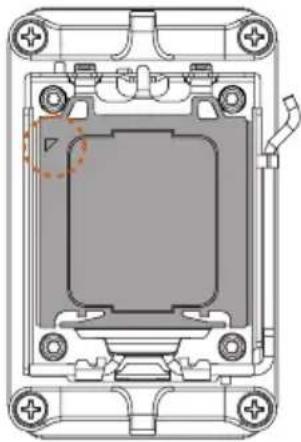
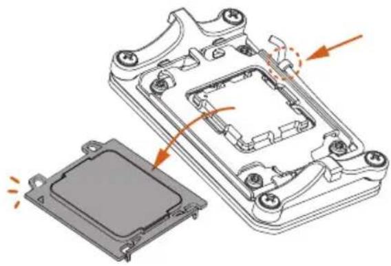
Turn your CPU to the correct orientation before opening the CPU socket cover.
1

natural_image
3D technical diagram of a device casing with labeled components A and B, showing internal structure and mounting points (no text or symbols beyond labels)2
natural_image
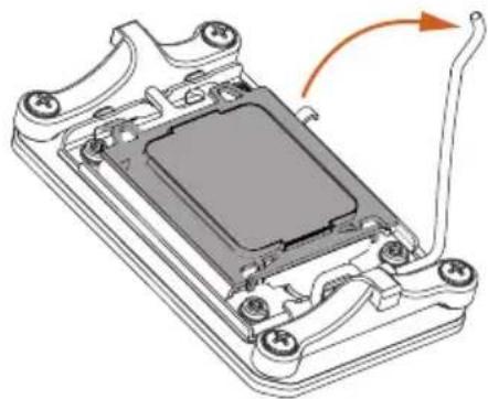
Technical diagram of a mechanical component with a highlighted section and directional arrow (no text or symbols)3
natural_image
Technical line drawing of a mechanical device with an open base and internal components, showing no text or symbols.4
natural_image
Technical line drawing of a mechanical device with internal components and a highlighted section (no text or symbols)
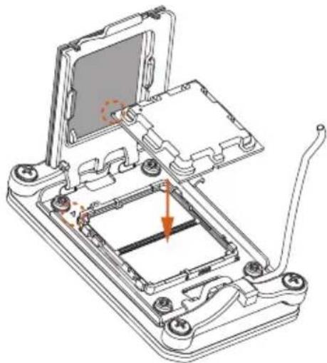
Carefully place the CPU in as flat as possible. Do not drop it.
5
natural_image
Technical line drawing of a mechanical device with internal components and a highlighted section (no text or symbols)6
natural_image
Technical illustration of a mechanical component with an arrow indicating rotation (no text or symbols present)!
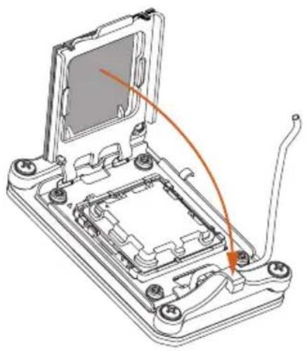
Make sure the CPU is aligned with the socket before locking it into place.
7
natural_image
Exploded view diagram of a computer case with internal components and highlighted areas (no text or symbols)!
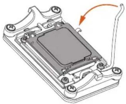
Make sure the black cover plate is always in place until it pops off when closing the socket lever.

Please save the cover if the processor is removed. The cover must be placed if you wish to return the motherboard for after service.
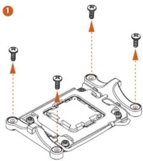
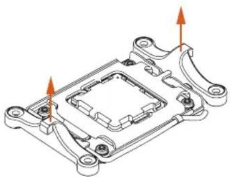
2.2 Installing the CPU Fan and Heatsink
After you install the CPU into this motherboard, it is necessary to install a larger heatsink and cooling fan to dissipate heat. You also need to spray thermal grease between the CPU and the heatsink to improve heat dissipation. Make sure that the CPU and the heatsink are securely fastened and in good contact with each other.

Please turn off the power or remove the power cord before changing a CPU or heatsink.
Installing the CPU Cooler
2
natural_image
Technical line drawing of a mechanical component with mounting holes and internal cavities (no text or symbols)3
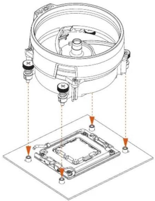
4
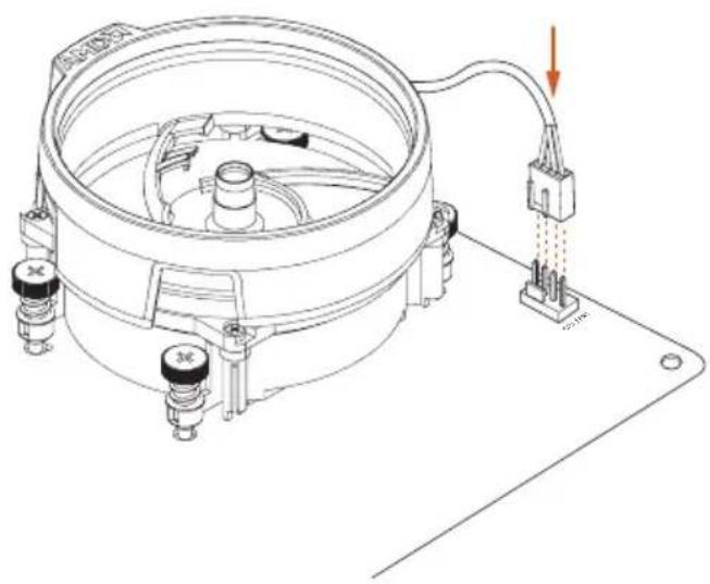
natural_image
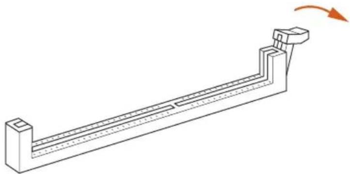
Technical line drawing of a mechanical device with attached wiring and mounting base (no text or symbols)2.3 Installing Memory Modules (DIMM)
This motherboard provides four 288-pin DDR5 (Double Data Rate 5) DIMM slots, and supports Dual Channel Memory Technology.

- For dual channel configuration, you always need to install identical (the same brand, speed, size and chip-type) DDR5 DIMM pairs.
- It is unable to activate Dual Channel Memory Technology with only one or three memory module installed.
- It is not allowed to install a DDR, DDR2, DDR3 or DDR4 memory module into a DDR5 slot; otherwise, this motherboard and DIMM may be damaged.
- The DIMM only fits in one correct orientation. It will cause permanent damage to the motherboard and the DIMM if you force the DIMM into the slot at incorrect orientation.
Recommended Memory Configuration
1 DIMM

2 DIMMs

4 DIMMs

The first boot may take some time.
Please be patient and refer to the following table for booting time.
*It may vary by different setups.
| Memory 1st boot after clear CMOS | |
| 2 x 16GB 90 sec | |
| 2 x 32GB 150 sec | |
| 4 x 16GB 170 sec | |
| 4 x 32GB 315 sec | |

The DIMM only fits in one correct orientation. It will cause permanent damage to the motherboard and the DIMM if you force the DIMM into the slot at incorrect orientation.
1
natural_image
Technical line drawing of a mechanical lever or support structure with a rotation arrow indicating motion (no text or symbols present)2
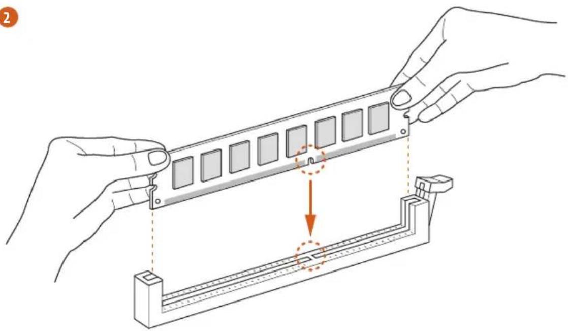
natural_image
Illustration of hands installing a mechanical component with a highlighted section (no text or symbols)3
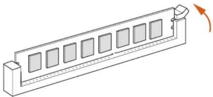
natural_image
Isometric line drawing of a rectangular electronic component with multiple slots and a curved arrow indicating rotation (no text or symbols)2.4 Expansion Slot (PCIe Slot)
There are 1 PCIe slot on the motherboard.

Before installing an expansion card, please make sure that the power supply is switched off or the power cord is unplugged. Please read the documentation of the expansion card and make necessary hardware settings for the card before you start the installation.
PCIe slot:
PCIE1 (PCIe 4.0 x16 slot) is used for PCIe x16 lane width graphics cards.
2.5 Jumpers Setup
The illustration shows how jumpers are setup. When the jumper cap is placed on the pins, the jumper is “Short”. If no jumper cap is placed on the pins, the jumper is “Open”.
Short
Open
Clear CMOS Jumper
(CLRCMOS1)
(see p.1, No. 12)

2-pin Jumper
Short: Clear CMOS
Open: Default
CLRCMOS1 allows you to clear the data in CMOS. The data in CMOS includes system setup information such as system password, date, time, and system setup parameters. To clear and reset the system parameters to default setup, please turn off the computer and unplug the power cord, then use a jumper cap to short the pins on CLRCMOS1 for 3 seconds. Please remember to remove the jumper cap after clearing the CMOS. If you need to clear the CMOS when you just finish updating the BIOS, you must boot up the system first, and then shut it down before you do the clear-CMOS action.

If you clear the CMOS, the case open may be detected. Please adjust the BIOS option "Clear Status" to clear the record of previous chassis intrusion status.
2.6 Onboard Headers and Connectors

Onboard headers and connectors are NOT jumpers. Do NOT place jumper caps over these headers and connectors. Placing jumper caps over the headers and connectors will cause permanent damage to the motherboard.
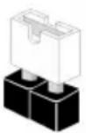
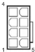
System Panel Header (9-pin PANEL1)
(see p.1, No.10)
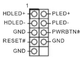
Connect the power button, reset button and system status indicator on the chassis to this header according to the pin assignments below. Note the positive and negative pins before connecting the cables.

PWRBTN (Power Button):
Connect to the power button on the chassis front panel. You may configure the way to turn off your system using the power button.
RESET (Reset Button):
Connect to the reset button on the chassis front panel. Press the reset button to restart the computer if the computer freezes and fails to perform a normal restart.
PLED (System Power LED):
Connect to the power status indicator on the chassis front panel. The LED is on when the system is operating. The LED keeps blinking when the system is in S1/S3 sleep state. The LED is off when the system is in S4 sleep state or powered off (S5).
HDLED (Hard Drive Activity LED):
Connect to the hard drive activity LED on the chassis front panel. The LED is on when the hard drive is reading or writing data.
The front panel design may differ by chassis. A front panel module mainly consists of power button, reset button, power LED, hard drive activity LED, speaker and etc. When connecting your chassis front panel module to this header, make sure the wire assignments and the pin assignments are matched correctly.
Serial ATA3 Connector
(SATA3_A1:
see p.1, No. 8)
(SATA3_A2:
see p.1, No. 9)
SATA3_A2
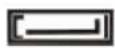
SATA3_A1
These two SATA3
connector supports SATA data cables for internal storage devices with up to 6.0 Gb/s data transfer rate.
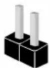
USB 2.0 Header
(9-pin USB_5_6)
(see p.1, No. 7)
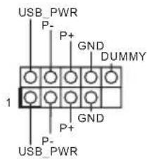
There is one header on this motherboard. This USB 2.0 header can support two ports.
Chassis Fan Connector
(4-pin CHA_FAN1)
(see p.1, No. 11)
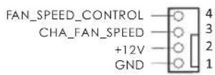
Please connect fan cable to the fan connector and match the black wire to the ground pin.
CPU Fan Connectors
(4-pin CPU_FAN1)
(see p.1, No. 2)
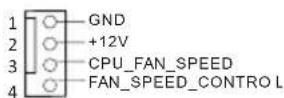
This motherboard
provides a 4-Pin CPU fan (Quiet Fan) connector.
If you plan to connect a 3-Pin CPU fan, please connect it to Pin 1-3.
ATX Power Connector
(24-pin ATXPWR1)
(see p.1, No. 6)

This motherboard provides a 24-pin ATX power connector. To use a 20-pin ATX power supply, please plug it along Pin 1 and Pin 13.
ATX 12V Power
Connector
(8-pin ATX12V1)
(see p.1, No. 1)
This motherboard provides a 8-pin ATX 12V power connectors. To use a 4-pin ATX power supply, please plug it along Pin 1 and Pin 5.
*Warning: Please make sure that the power cable connected is for the CPU and not the graphics card. Do not plug the PCIe power cable to this connector.
Chassis Intrusion Header
(2-pin CI1)
(see p.1, No. 5)
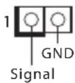
This motherboard supports CASE OPEN detection feature that detects if the chassis cove has been removed. This feature requires a chassis with chassis intrusion detection design.
2.7 Smart Button
The motherboard has a smart button: BIOS Flashback Button, allowing users to flash the BIOS.
BIOS Flashback Button
(BIOS_FB1) (see p.5, No. 6)
BIOS Flashback Button allows users to flash the BIOS.
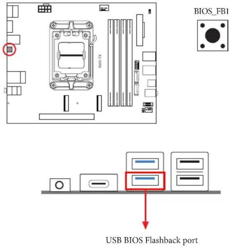
ASRock BIOS Flashback feature allows you to update BIOS without powering on the system, even without CPU.

Before using the BIOS Flashback function, please suspend BitLocker and any encryption or security relying on the TPM. Make sure that you have already stored and backup-ed the recovery key. If the recovery key is missing while encryption is active, the data will stay encrypted and the system will not boot into the operating system. It is recommended to disable fTPM before updating the BIOS. Otherwise an unpredictable failure may occur.
To use the USB BIOS Flashback function, Please follow the steps below.
- Download the latest BIOS file from ASRock's website: http://www.asrock.com.
- Copy the BIOS file to your USB flash drive. Please make sure the file system of your USB flash drive must be FAT32.
- Extract BIOS file from the zip file.
- Rename the file to "creative.rom" and save it to the root directory of X: USB flash drive.
- Plug the 24 pin power connector to the motherboard. Then turn on the power supply's AC switch.
*There is no need to power on the system.
- Then plug your USB drive to the USB BIOS Flashback port.
- Press the BIOS Flashback Switch for about three seconds. Then the LED starts to blink.
- Wait until the LED stops blinking, indicating that BIOS flashing has been completed.
*If the LED light turns solid green, this means that the BIOS Flashback is not operating properly. Please make sure that you plug the USB drive to the USB BIOS Flashback port.
**If the LED does not light up at all then please disconnect power from the system and remove/disconnect the CMOS battery from the motherboard for several minutes. Reconnect power and battery and try again.
2.8 M.2 WiFi/BT Module Installation Guide
The M.2 is a small size and versatile card edge connector that aims to replace mPCIe and mSATA. The M.2 Socket (Key E) supports type 2230 WiFi/BT module.
Installing the WiFi/BT module
natural_image
Pure technical line drawing of a rectangular component with three side tabs and a small bolt symbol (no text or labels)Step 1
Prepare a type 2230 WiFi/BT module and the screw.
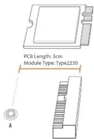
Step 2
Find the nut location to be used.
Step 3
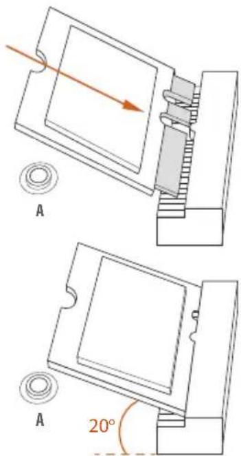
Gently insert the WiFi/BT module into the M.2 slot. Please be aware that the module only fits in one orientation.
natural_image
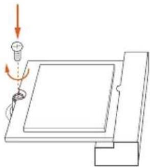
Diagram of a mechanical setup with a screw and spring, showing motion direction (no text or symbols)Step 4
Tighten the screw with a screwdriver to secure the module into place. Please do not overtighten the screw as this might damage the module.
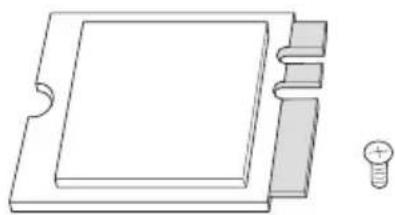
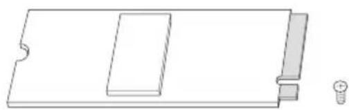
2.9 M.2 SSD Module Installation Guide
The M.2 is a small size and versatile card edge connector that aims to replace mPCIe and mSATA. The Blazing M.2 Socket (M2_1, Key M) supports type 2280 PCIe Gen5x4 (128 Gb/s) mode. The Hyper M.2 Socket (M2_2, Key M) supports type 2280 PCIe Gen4x4 (64 Gb/s) mode.
Installing the M.2 SSD Module
natural_image
Simple line drawing of a rectangular object with a slot and a small bulb beside it (no text or symbols)Step 1
Prepare a M.2 SSD Module and the screw.
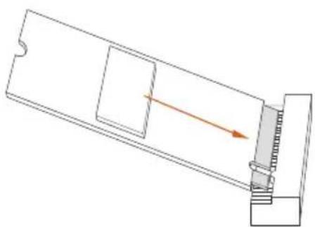
natural_image
Pure mechanical diagram showing a lever mechanism with no text or symbolsStep 2
Gently insert the M.2 SSD module into the M.2 slot. Please be aware that the M.2 SSD module only fits in one orientation.
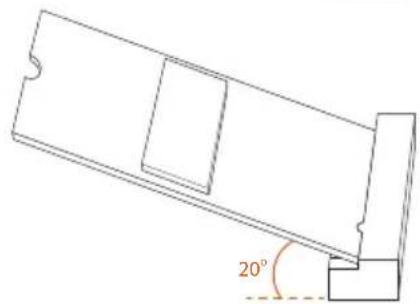
natural_image
Technical line drawing of a mechanical component with a 20-degree angle标注 (no text or symbols beyond the angle marker)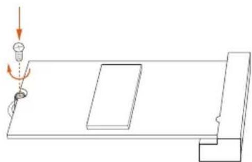
natural_image
Pure technical diagram showing a mechanical assembly with no text, numbers, or symbolsStep 3
Tighten the screw with a screwdriver to secure the module into place. Please do not overtighten the screw as this might damage the module.
1 Einleitung
• 2 x Connettori SATA3 6,0 Gb/s
E/S do painel frontal
• 1 x Entrada de Fone de ouvido
• 2 x Portas Tipo A USB 3.2 Gen1
• 1 x Porta Tipo C USB 3.2 Gen1
• 2 x Portas USB 2.0
• 2 x Conectores SATA3 6,0 Gb/s
• 1 x Soket Headphone/Headset
Depan
• 2 x Port USB 3.2 Gen1 Type-A
• 1 x Port USB 3.2 Gen1 Tipe-C
- 2 x Port USB 2.0
I/O Panel
- 1 x Port HDMI
Belakang
- 2 x DisplayPort 1.4
• 2 x Port USB 3.2 Gen1
- 2 x Port USB 2.0
• 1 x Port LAN RJ-45
• 1 x Tombol BIOS Flashback
- Soket Audio HD: Saluran Masuk/Speaker Depan/Mikrofon
Penyimpanan
CPU:
- 1 x Soket Blazing M.2 (M2_1, Key M), mendukung PCIe tipe 2280 mode Gen5x4 (128 Gb/s)*
- 1 x Soket Hyper M.2 (M2_2, Key M), mendukung PCIe tipe 2280 mode Gen4x4 (64 Gb/s)*
ASMedia ASM1061:
• 2 x Konektor SATA3 6,0 Gb/s
DECLARATION OF CONFORMITY
Per FCC Part 2 Section 2.1077(a)

Product Name : Motherboard
Model Number: X600-ITX
Conforms to the following specifications:
☒ FCC Part 15, Subpart B, Unintentional Radiators
Supplementary Information:
This device complies with part 15 of the FCC Rules. Operation is subject to the following two conditions: (1) This device may not cause harmful interference, and (2) this device must accept any interference received, including interference that may cause undesired operation.
EU Declaration of Conformity
For the following equipment:
Motherboard
(Product Name)
X600-ITX
(Model Designation / Trade Name)
EMC Directive - 2014/30/EU
EN 55032: 2015 / A11: 2020, EN 55035: 2017 / A11: 2020
EN IEC 61000-3-2: 2019, EN 61000-3-3: 2013
RoHS Directive - 2011/65/EU
2015/863/EU, EN IEC 63000:2018

(EU conformity marking)
EU Declaration of Conformity
Product:
Product Motherboard
Model X600-ITX
Authorized Representative (UK-GB):
Name: Gary Tsui
Address: Bijsterhuizen 11-11, 6546 AR Nijmegen, The Netherlands
Contact person: Gary Tsui
This declaration is issued under the sole responsibility of the mentioned Manufacturer. The subject equipment under declaration is in conformity with the UK-GB Regulation(s) below:
The Electromagnetic Compatibility Regulations 2016 (S.I. 2016/1091)
EN 55032: 2015 / A11: 2020, EN 55035: 2017 / A11: 2020, EN IEC 61000-3-2: 2019, EN 61000-3-3: 2013
The Restriction of the Use of Certain Hazardous Substances in Electrical and Electronic Equipment Regulations 2012
2015/863/EU, EN IEC 63000:2018
The following manufacturer outside the UK-GB is responsible for this declaration:
BSMI 限用物質及元素清單