DeskMini GTX B360 - Desktop computer ASROCK - Free user manual and instructions
Find the device manual for free DeskMini GTX B360 ASROCK in PDF.

User questions about DeskMini GTX B360 ASROCK
0 question about this device. Answer the ones you know or ask your own.
Ask a new question about this device
Download the instructions for your Desktop computer in PDF format for free! Find your manual DeskMini GTX B360 - ASROCK and take your electronic device back in hand. On this page are published all the documents necessary for the use of your device. DeskMini GTX B360 by ASROCK.
USER MANUAL DeskMini GTX B360 ASROCK
Z390M-STX MXM B360M-STX MXM
natural_image
Illustration of a modern electronics assembly line with circuit board overlay (no text or symbols)Version 1.0
Published September 2018
This device complies with Part 15 of the FCC Rules. Operation is subject to the following two conditions:
(1) this device may not cause harmful interference, and
(2) this device must accept any interference received, including interference that
may cause undesired operation.
CALIFORNIA, USA ONLY
The Lithium battery adopted on this motherboard contains Perchlorate, a toxic substance controlled in Perchlorate Beat Management Practices (BMP) regulations passed by the California Legislature. When you discard the Lithium battery in California, USA, please follow the related regulations in advance.
"Perchlorate Material-special handling may apply, see www.disc.ca.gov/hazardouswaste/perchlorate"

AUSTRALIA ONLY
Our goods come with guarantees that cannot be excluded under the Australian Consumer Law. You are entitled to a replacement or refund for a major failure and compensation for any other reasonably foreseeable loss or damage caused by our goods. You are also entitled to have the goods repaired or replaced if the goods fail to be of acceptable quality and the failure does not amount to a major failure.
The terms HDMI ^® and HDMI High-Definition Multimedia Interface, and the HDMI logo are trademarks or registered trademarks of HDMI Licensing LLC in the United States and other countries.

Contents
Chapter 1 Introduction 1
1.1 Package Contents 1
1.2 Specifications 2
1.3 Motherboard Layout 6
1.4 Front Panel 12
1.5 Rear Panel 13
Chapter 2 Installation 15
2.1 Installing the CPU 16
2.2 Installing the CPU Fan and Heatsink 19
2.3 Installing Memory Modules (SO-DIMM) 20
2.4 Installing Mobile PCI Express Module (MXM) 22
2.5 Onboard Headers and Connectors 32
2.6 M.2 WiFi/BT Module and Intel ^ CNVi (Integrated WiFi/BT) Installation Guide 35
2.7 M.2_SSD (NGFF) Module Installation Guide (M2_1, M2_3) 37
2.8 M.2_SSD (NGFF) Module Installation Guide (M2_2) 41
2.9 Polychrome RGB 46
Chapter 3 Software and Utilities Operation 48
3.1 Installing Drivers 48
Chapter 4 UEFI SETUP UTILITY 49
4.3 Advanced Mode 51
4.3.1 UEFI Menu Bar 51
4.3.2 Navigation Keys 52
4.4 Main Screen 53
4.5 OC Tweaker Screen 54
4.6 Advanced Screen 63
4.6.1 CPU Configuration 64
4.6.2 Chipset Configuration 66
4.6.3 Storage Configuration 69
4.6.4 ACPI Configuration 70
4.6.5 USB Configuration 71
4.6.6 Trusted Computing 72
4.7 Tools 73
4.8 Hardware Health Event Monitoring Screen 75
4.9 Security Screen 77
4.10 Boot Screen 78
4.11 Exit Screen 80
7390M-STX MXM / B360M-STX MXM
Chapter 1 Introduction
In this documentation, Chapter 1 and 2 contains the introduction of the motherboard and step-by-step installation guides. Chapter 3 contains the operation guide of the software and utilities. Chapter 4 contains the configuration guide of the BIOS setup.

Because the motherboard specifications and the BIOS software might be updated, the content of this documentation will be subject to change without notice.
1.1 Package Contents
• Z390M-STX MXM / B360M-STX MXM Motherboard (Micro-STX Form Factor)
• 7390M STX MXM / R360M STX MXM Quick Installation Guide
• 7390M-STX MXM / B360M-STX MXM Support CD
• 1 x L/O Panel Shield
• 2 x Serial ATA (SATA) Data with Power Cables (Optional)
• 4 x Screws for M.2 Socket (Optional)
• 2 x Screws for MXM Slot (Optional)
1.2 Specifications
Platform • Micro-STX Form Factor
CPU Z390M-STX MXM:
- Supports 9^th and 8^th Gen Intel CoreTM Processors (Socket 1151)
- 5+1 Power Phase design
• Supports Intel® Turbo Boost 2.0 Technology
• Supports Intel® K Series unlocked CPUs
• Supports BCLK Full-range Overclocking
B360M-STX MXM:
• Supports 9 ^th and 8 ^th Gen Intel ^® Core ^TM Processors (Socket
1151) (Up to TDP 65W CPU)
• 5+1 Power Phase design
• Supports Intel® Turbo Boost 2.0 Technology
Chipset Intel® Z390 (for Z390M-STX MXM)
- Intel® B360 (for B360M-STX MXM)
Memory Z390M-STX MXM:
• Dual Channel DDR4 Memory Technology
• 2 x DDR4 SO-DIMM Slots
• Supports DDR4 3200+(OC)*/2935(OC)/2800(OC)/
2666/2400/2133 non-ECC, un-buffered memory
• Max. capacity of system memory: 32GB
• Supports Intel ^® Extreme Memory Profile (XMP) 2.0
B360M-STX MXM:
• Dual Channel DDR4 Memory Technology
• 2 x DDR4 SO-DIMM Slots
• Supports DDR4 2666/2400/2133 non-ECC, un-buffered memory
• Max. capacity of system memory: 32GB
• Supports Intel ^® Extreme Memory Profile (XMP) 2.0
Onboard Graphics
- Intel® UHD Graphics Built in Visuals and the VGA outputs can be supported only with processors which are GPU integrated.
- Supports Intel® UHD Graphics Built-in Visuals: Intel® Quick Sync Video with AVC, MVC (S3D) and MPEG 2 Full HW Encoder1, Intel® InTru™ 3D, Intel® Clear Video HD Technology, Intel® Insider™, Intel® UHD Graphics
- DirectX 12
- HWAFencode/Decode: AVC/H.264, HEVC/H.265 8-bit, HEVC/H.265 10-bit, VP8, VP9 8-bit, VP9 10-bit (Decode only), MPEG2, MJPEG, VC-1 (Decode only)
- Supports HDMI with max. resolution up to 4K x 2K (1096x2160) @ 30Hz (on HDMI1)
• Supports Auto Lip Sync, Deep Color (12bpc), xvYCC and HBR (High Bit Rate Audio) with HDMI Port (Compliant HDMI monitor is required)
• Supports HDCP with HDMI Port
• Supports 4K Ultra HD (UHD) playback with HDMI Port
External Graphics
- Supports HDMI with max. resolution up to 4K x 2K (-1096x2160) @ 60Hz (on HDMI) ^4
• Supports DisplayPort 1.2 with max. resolution up to 4K x 2K (4096x2304) @ 60Hz* - Supports Mini DisplayPort 1.2 with max. resolution up to 4K x 2K (4096x2304) @ 60Hz ^4
* The HDMI, DisplayPort and Mini DisplayPort ports are only available when a MXM graphics card is installed.
* The resolution of HDMI, DisplayPort and Mini DisplayPort may vary based on different graphics cards.
Audio
• Realtek ALC233 Audio Codoc
• 1 x Headphone, Headset Jack
- 1 x MIC In
LAN
• Gigabit LAN 10/100/1000 Mb/s
Front
Panel I/O
• 1 x Headphone/Headset Jack
- 1 x USB 3.1 Gen2 Type A Port (Supports ESD Protection)
• 1 x USB 3.1 Gen2 Type-C Port (Supports ESD Protection)
- 1 x Microphone Input Jack
Rear Panel
I/O
- 1 x DC Power Din Jack (Compatible with the 19V power adapter)
• 2 x HDMI Ports
• 1 x DisplayPort - 1 x Mini DisplayPort
- 1 x RJ-45 LAN Port with LED (ACT/LINK LED and SPEED LED)
Z390M-STX MXM:
- 2 x USB 3.1 Gen1 Ports (Supports ESD Protection (Full Spike Protection))
- 2 x USB 3.1 Gen2 Ports (Supports ESD Protection (Full Spike Protection))
B360M-STX MXM:
- 2 x USB 3.1 Gen1 Ports (Supports ESD Protection (Full Spike Protection))
- 2 x USB 2.0 Ports (Supports ESD Protection (Full Spike Protection))
Storage
Z390M-STX MXM:
- 2 x SATA3 6.0 Gb/s with Power Connectors, support RAID (RAID 0, RAID 1, RAID 5, RAID 10, Intel Rapid Storage Technology 16), NCQ, AHCI and Hot Plug*
- 2 x Ultra M.2 Sockets (M2_1 and M2_3), supports M Key type 2260/2280 M.2 SATA3 6.0 Gb/s module and M.2 PCI Express module up to Gen3 x4 (32 Gb/s)
- 1 x Ultra M.2 Socket (M2_2), supports M Key type 2242/2260/2280 M.2 PCI Express module up to Gen3 x4 (32 Gb/s) ^4
* Supports Intel® Optane™ Technology
* Supports NVMe SSD as boot disks
B360M-STX MXM:
7390M-STX MXM / B360M-STX MXM
- 1 x M.2 Socket (M2_3), supports M Key type 2260/2280 M.2 SATA3 6.0 Gb/s module ^4
- 1 x Ultra M.2 Socket (M2_2), supports M Key type 2242/2260/2280 M.2 PCI Express module up to Gen3 x4 (32 Gb/s) ^a
* Supports Intel ^5 Optane ^7,14 Technology (on M2_2)
* Supports NVMe SSD as boot disks
Connector
- 1x RGB LED Header
* Supports in total up to 12V/3A, 36W LED Strip - 1 x Addressable LED Header (for Z390M-STX MXM only)
* Supports in total up to 5V/3A, 15W LED Strip
• 2 x CPU Fan Connectors (4 pin)
* The CPU Fan Connector supports the CPU fan of maximum 1A (12W) fan power. - 1 x GPU Fan Connector (5-pin)
• 1 x 3W Audio AMP Output Wafer Header - 2 x USB 2.0 Headers (Support 4 USB 2.0 ports) (Supports ESD Protection)
BIOS
• AMI UEFI Legal BIOS with multilingual GUI support
- ACPI 6.0 Compliant wake up events
- SMBIOS 2.7 Support
- DRAM Voltage, VCORE Multi-adjustment
Hardware
• Temperature Sensing: CPU
• Fan Tachometer: CPU
- Quiet Fan (Auto adjust chassis fan speed by CPU temperature): CPU
• Voltage monitoring: -12V, +5V, +3.3V, CPU Vcore, DRAM
OS
• Microsoft Windows 10 64 bit
Certifica-
· FCC, CE
- ErP/1uP ready (ErP/1uP ready power supply is required)
1.3 Motherboard Layout
Z390M-STX MXM
Top View

text_image
DC Jack LWNT LIWH 2.85 V 1.16e-4 1.1500V 2.2500V 2.2500V 2.2500V 2.2500V 2.2500V 2.2500V MXM1 WDG S - SD ZAD RoHS Z390M-S TX MXM DDR4_A1 DDR4_B1 Mio In 1/V1/2 USB S 1.16e-4 078_1 1.16e-4 1.16e-4 1.16e-4 1.16e-4 1.16e-4 1.16e-4 1.16e-4 1.16e-4 1.16e-4 1.16e-4 1.16e-4 1.16e-4 1.16e-4 1.25V +5V +5V +5V +5V +5V +5V +5V +5V +5V +5V +5V +5V7390M-STX MXM / B360M-STX MXM
Bottom View
text_image
Intel Chipset CMOS Battery 12 13 14 15 16 17 18 19 20 21 22 23 24 25 26 27 28 29 30 31 32 33 34 35 36 37 38 39 40 41 42 43 44 45 46 47 48 49 50 51 52 53 54 55 56 57 58 59 60 61 62 63 64 65 66 67 68 69 70 71 72No. Description
1 CPU Fan Connector (CPU FAN1)
2 2 x 260-pin DDR4 SO DIMM Slots (DDR4_A1, DDR4_B1)
3 CPU Fan Connector (CPU_FAN2)
4 USB 2.0 Header (USB_2_3)
5 USB 2.0 Header (USB_4_5)
6 System Panel Header (PANEL1)
7 3W Audio AMP Output Water Header (SPEAKER1)
8 RGB LED Header (RGB LED1)
9 Addressable LED Header (ADDR LED1)
10 Clear CMOS Pad (CLRCMOS1)
11 5-Pin GPU Fan Connector (GPU_FAN1)
12 SATA3 Connector (SATA1)
13 SATA3 Connector (SATA2)
14 Clear CMOS Pad (CLRCMOS2)
B360M-STX MXM
Top View
text_image
BC Jack LANT HOMT MOD1.1 Gen M.1555 USB 5.4 T.200A M.1587 INCH DC MXM1 B3 60M-S TX MXM DDR4_A1 DDR4_B1 Nix In M2/5-0 USB 3.1 Geno USB_1 Headwave Inverter RoHS 1 2 3 4 3 0
text_image
INTAT 12475 12475 12475 12475 12475 12475 12475 12475 12475 12475 12475 12475 12475 12475 12475 12475 12475 1239 Intel Chipset Intel Chipset COS COS7390M-STX MXM / B360M-STX MXM
No. Description
1 CPU Fan Connector (CPU FAN1)
2.2 x 260-pin DDR4 SO DIMM Slots (DDR4_A1, DDR4_B1)
3 CPU Fan Connector (CPU_FAN2)
4 USB 2.0 Header (USB_2_3)
5 USB 2.0 Header (USB_4_5)
6 System Panel Header (PANEL1)
7 3W Audio AMP Output Wafer Header (SPEAKER1)
8 RGB LED Header (RGB LED1)
9 Clear CMOS Pad (CLRCMOS1)
10.5 Pin GPU Fan Connector (GPU_FAN1)
11 SATA3 Connector (SATA1)
12 SATA3 Connector (SATA2)
13 Clear CMOS Pad (CLRCMOS2)
1.4 Front Panel
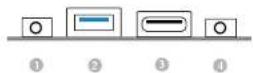
No. Description No. Description
1 Headphone/Headset Jack (AUDIO1) 3 USB 3.1 Gen1 Type-C Port (USB 10)
2 USB 3.1 Gen2 Type A Port (USB_1) 4 Microphone Input (AUDIO2)
7390M-STX MXM / B360M-STX MXM
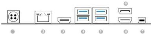
1.5 Rear Panel
Z390M-STX MXM
text_image
Diagram showing seven labeled items with corresponding icons, likely representing a product or appliance layout.No. Description No. Description
1 DC Power Din Jack 5 USB 3.1 Gen2 Ports (USB 6-7)
(Supports 19V Power Adapters) 6 HDMI Port (HDMI)
2 LAN RJ-45 Port ^7 Mini DisplayPort (DP2)
3 HDMI Port (HDMI1) 8 DisplayPort (DP_1)
4 USB 3.1 Gen1 Ports (USB 8 9)
* After not linked LEDs on each LAN port. Please refer to the table below for the LAN port LED indications.
SPEED LED

Activity / Link LED Speed LED
Status Description Status Description
| Off No Link Off | 10Mbps connection | ||
| Blinking | Data Activity | Orange | 100Mbps connection |
| On | Link | Green | 1Gbps connection |
B360M-STX MXM:
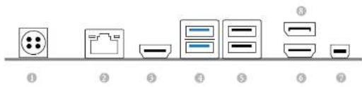
text_image
Diagram showing seven electronic component labels with corresponding icons, labeled ① to ⑦.No. Description No. Description
1 DC Power Din Jack 5 USB 2.0 Ports (USB_6_7)
(Supports 19V Power Adapters) 6 HDMI Port (HDMI)
2 LAN RJ-45 Port 7 Mini DisplayPort (DP2)
3 HDMI Port (HDMI) 8 DisplayPort (DP_1)
4 USB 3.1 Gen1 Ports (USB 8 9)
* There are two LEDs on each LAN port. Please refer to the table below for the LAN port LED indications.
MELLED

Activity / Link LED Speed LED
Status Description Status Description
| Off No Link Off 10Mbps connection | |||
| Blinking | Data Activity | Orange | 100Mbps connection |
| On | Link | Green | 1Gbps connection |
Chapter 2 Installation
This is an Micro-STX form factor motherboard. Before you install the motherboard, study the configuration of your chassis to ensure that the motherboard fits into it.
Pre-installation Precautions
Take note of the following precautions before you install motherboard components or change any motherboard settings.
- Make sure to unplug the power cord before installing or removing the motherboard components. Failure to do so may cause physical injuries and damages to motherboard components.
- In order to avoid damage from static electricity to the motherboard's components, NEVER place your motherboard directly on a carpet. Also remember to use a grounded wrist strap or touch a safety grounded object before you handle the components.
- Hold components by the edges and do not touch the ICs.
- Whenever you uninstall any components, place them on a grounded anti-static pad or in the bag that comes with the components.
- When placing screws to secure the motherboard to the chassis, please do not over tighten the screws! Doing so may damage the motherboard.
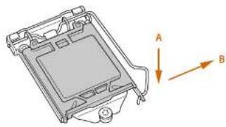
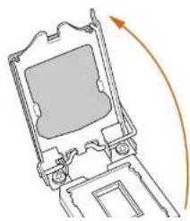
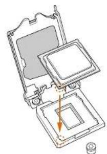
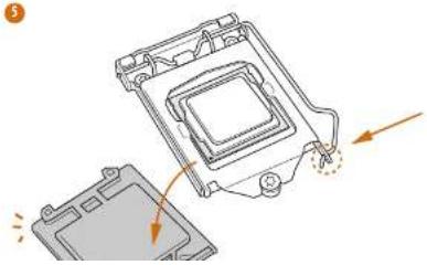
2.1 Installing the CPU

- Before you insert the 125-Pin CPU into the socket, please check if the PnP cap is on the socket; if the CPU surface is much, or if there are any hand pins in the socket. Do not force to move the CPU into the socket if above situation is found. Otherwise, the CPU will be seriously damaged.
- Upping all power cables before installing the CPU.
①
natural_image
Technical diagram of a mechanical component with labeled arrows A and B, showing internal structure and mounting base (no text or symbols beyond labels)2
natural_image
Diagram of a mechanical device with an arrow indicating rotational motion (no text or symbols)7390M-STX MXM / B360M-STX MXM
3
natural_image
Technical line drawing of a mechanical assembly with no visible text or symbols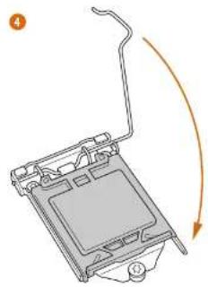
natural_image
Diagram of a device with an arrow indicating rotation or movement, no text or symbols present5
natural_image
Technical illustration of a mechanical component with arrows indicating motion or assembly (no text or symbols)
Please serve and replace the cover if the process is removed. The cover must be placed if you wish to return the motherhood for after service.
7390M-STX MXM / B360M-STX MXM
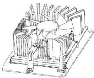
2.2 Installing the CPU Fan and Heatsink

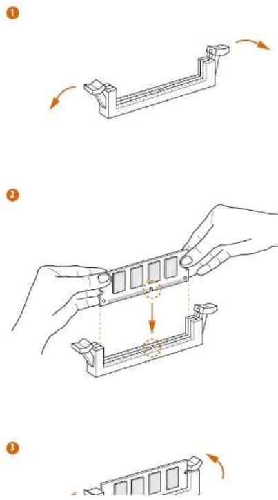
2.3 Installing Memory Modules (SO-DIMM)
This motherboard provides two 260 pin DDR4 (Double Data Rate 1) SO DIMM slots.

It is not allowed to manage a DDR, DDR2 or DDR3 memory module into a DDR4 slot otherwise this motherboard and SO DDRM may be damaged.

The SI-DMM only fits in one correct orientation. It will cause permanent damage to the motherboard and the SI-DMM if you force the SI-DMM into the slot at incorrect orientation.
7390M-STX MXM / B360M-STX MXM
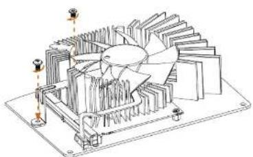
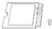
2.4 Installing Mobile PCI Express Module (MXM)
This motherboard provides a Mobile PCI Express Module (MXM) Slot.
Installing a Type A MXM Card (70mm)
1
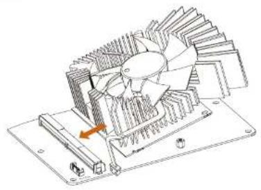
natural_image
Technical line drawing of a mechanical fan assembly with no visible text or symbols2

natural_image
Diagram of a mechanical or architectural structure with layered components and two vertical measurement indicators (no text or symbols present)7390M-STX MXM / B360M-STX MXM
3

natural_image
Technical line drawing of a mechanical fan assembly with cooling fins and mounting bracket (no text or symbols)4
natural_image
Technical line drawing of a mechanical fan or turbine assembly with no visible text or symbols
natural_image
Technical line drawing of a mechanical fan or turbine assembly with cooling fins and mounting base (no text or symbols)7390M-STX MXM / B360M-STX MXM
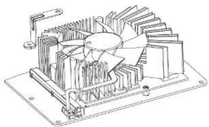
Installing a Type B MXM Card (105mm)
1
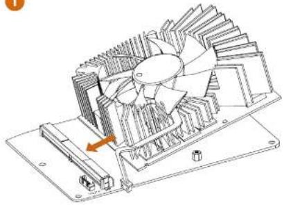
natural_image
Technical line drawing of a mechanical fan assembly with cooling fins and mounting base (no text or symbols)
natural_image
Technical line drawing of a mechanical fan assembly with no visible text or symbols3
natural_image
Technical line drawing of a mechanical cooling fan assembly (no text or symbols)4

natural_image
Technical line drawing of a mechanical fan assembly with cooling fins and mounting base (no text or symbols)7390M-STX MXM / B360M-STX MXM

natural_image
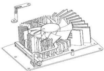
Technical line drawing of a mechanical cooling fan assembly (no text or symbols)Installing a Type B+ MXM Card (105mm-113mm)
1
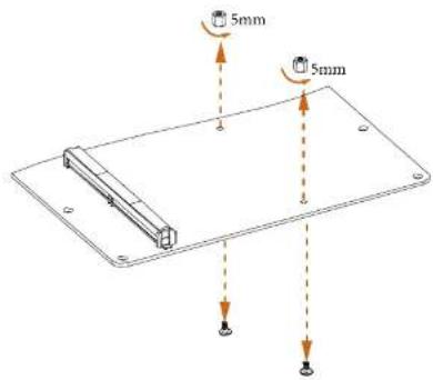
text_image
5mm 5mm2
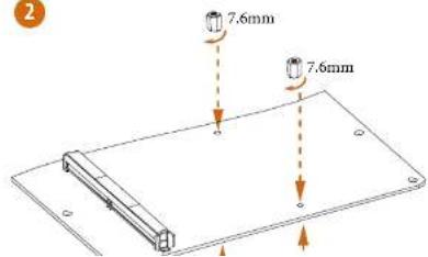
text_image
2 7.6mm 7.6mm7390M-STX MXM / B360M-STX MXM
3

natural_image
Technical line drawing of a mechanical fan assembly with an arrow indicating rotation direction (no text or symbols)4

natural_image
Technical line drawing of a mechanical fan assembly with mounting base (no text or symbols)5
natural_image
Technical line drawing of a mechanical fan assembly with cooling fins and mounting bracket (no text or symbols)6

natural_image
Technical line drawing of a mechanical fan assembly with no visible text or symbols7390M-STX MXM / B360M-STX MXM
7
natural_image
Technical line drawing of a mechanical fan or turbine assembly with cooling fins and mounting base (no text or symbols)2.5 Onboard Headers and Connectors

Outboard headers and connectors are NOT jumpers. The NOT place jumper caps over these headers and connectors. Placing jumper caps over the headers and connectors will cause permanent damage to the motherboard.
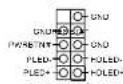
System Panel Header
(9 pin PANEL)
(see p.6 or p.9, No. 6)
Connect the power
hutton, reset hutton and
system status indicator on
the chassis to this header
according to the pin
assignments below. Note
the positive and negative
pins before connecting
the cables.

PWBTN (Power Button):
Connect to the power button on the chassis front panel. You may configure the way to turn off your system using the power button.
RESET (Reset Button)
Connect to the reset button on the chassis front panel. Press the reset button to restart the computer of the computer freezer and fails to perform a normal restart.
PLED (System Power LED):
Connected to the power status indicator on the class front point. The LED is on when the system is operating. The LED keeps blinking when the system is in 51/53 sleep state. The LED is off when the system is in 54 sleep state or powered off (55).
HDLED (Hard Drive Activity LED):
Connect to the hard drive activity / I/O on the classic front panel. The I/O is on when the hard drive is reading or writing data.
The front panel design may differ by chassis. A front panel module correctly consists of power button, reset button, power LED, hand drive activity LED, speaker and etc. When connecting your chassis from panel module to this header, make sure the write assignments and the pin assignments are matched correctly.
Serial ATA3 Connectors
(see p.7, No. 12 and 13)
(see p.10, No. 11 and 12)
These two SATA3
connectors support SATA
data cables for internal
storage devices with up to
6.0 Gb/s data transfer rate.
*The SATA3 connectors
support 2.5-inch hard
drive (+5V) and do not
support 3.5-inch hard
drive (+12V)
PIN Signal Name PIN Signal Name
| 1 GND 11 N/A | ||
| 2 LVDS_TX-12.5V | ||
| 3 LVDS_TX-13.5V | ||
| 4 GND | 14 | 5V |
| 5 GND 13.5V | ||
| 6 LVDS_RX | 16 | 3V |
| 7 LVDS_RX-17 N/A | ||
| 8 GND 18 GND | ||
| 9 GND | 19 | GND |
| 10 GND | 20 | GND |
USB 2.0 Headers
(9-pin USB 2 3)
(see p.6 or p.9, No. 4)
(9-pin USB_4_5)
(see p.6 or p.9, No. 5)
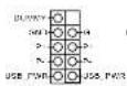
There are two USB
2.0 headers on this
motherboard.
3W Audio AMP Output
Wafer Header
(4-pin SPEAKER)
(see p.6 or p.9, No. 7)

Please connect the chassis
speaker to this header.
CPU Fan Connectors
(4 pin CPU_FAN1)
(see p.6 or p.9, No. 1)
(4-pin CPU FAN21)
This motherboard
provides two 4 Pin CPU
fan (Quiet Fan)
connectors. If you plan to
| GPU Fan Connector(5-pin GPU_FAN1)(see p.6, No. 11)(see p.9, No. 10) |  | This motherboardprovides a 5-Pin GPU fanconnector for connectingyour GPU fan. |
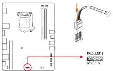
| RGB LED Header(4 pin RGB_LED1)(see p.6 or p.9, No. 8) |  | The RGB header is used toconnect RGB LED extensioncable which allows users tochoose from various LEDlighting effects.Caution: Never install the RGBLED cable in the wrong orientation; otherwise, the cable maybe damaged.* Please refer to page 46 forfurther instructions on these twoheaders. |
| Addressable LED Header(3-pin ADDR_LED1)(see p.6, No. 9)(for Z390M-5TX MXMonly) |  | This header is used to connectAddressable LED extension cablewhich allows users to choose(from various LED) lightingeffects.Caution: Never install theAddressable LED cable in thewrong orientation; otherwise,the cable may be damaged.*Please refer to page 47 forfurther instructions on thisheader. |
| Clear CMOS Pads(CTR/MOSI) | [wwzn] | The Clear CMOS Pad allows youto clear the data in CMOS. To |
2.6 M.2 WiFi/BT Module and Intel® CNVi (Integrated WiFi/BT) Installation Guide
The M.2, also known as the Next Generation Form Factor (NGFF), is a small size and versatile card edge connector that aims to replace mPCIe and mSATA. The M.2 Socket (Key E) supports type 2230 WiFi/B1 module and Intel® CNVi (Integrated WiFi/B1).
* The M.2 socket does not support SATA M.2 SSDs.

Before you install Intel® Integrated Connectivity (CNVI) module, be sure to turn off the AC power.
Installing the WiFi/BT module or Intel® CNVi (Integrated WiFi/BT)
Step 1
Prepare a type 2230 WiFi/BT module or Intel® CNVI (Integrated WiFi/BT) and the screw.
Step 2
Find the nut location to be used.

Step 3
Gently insert the WiFi/BT module or Intel® CNVi (Integrated WiFi/BT) into the M.2 slot. Please be aware that the module only fits in one orientation.
Step 4
Tighten the screw with a screwdriver to secure the module into place. Please do not overtighten the screw as this might damage the module.
7390M-STX MXM / B360M-STX MXM
2.7 M.2\_SSD (NGFF) Module Installation Guide (M2\_1, M2\_3)
The M.2, also known as the Next Generation Form Factor (NGFF), is a small size and versatile card edge connector that aims to replace mPCIe and mSATA.
Z390M-STX MXM:
The Ultra M.2 Sockets (M2_1 and M2_3) support M Key type 2260/2280 M.2 SATA A3 6.0 Gb/s module and M.2 PCI Express module up to Gen3 x4 (32 Gb/s)
B360M-STX MXM:
The Ultra M.2 Socket (M2_1) supports M Key type 2260/2280 M.2 SATA3 6.0 Gb/s module and M.2 PCI Express module up to Gen3 x4 (32 Gb/s) The M.2 Socket (M2_3) supports type 2260/2280 M.2 SATA3 6.0 Gb/s module.
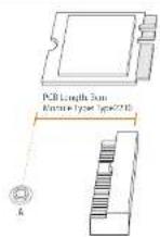
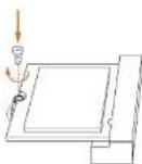
Installing the M.2\_SSD (NGFF) Module

Step 1
Prepare a M.2 SSD (NGIT) module and the screw.

text_image
Technical diagram showing a mechanical assembly with labeled components and dimension linesStep 2
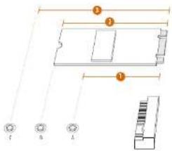
Depending on the PCB type and length of your M.2 SSD (NGFF) module, find the corresponding not location to be used.
No.12
Nut Location A B
PCB Length 6cm 8cm
Module Type Type2260 Type 2280
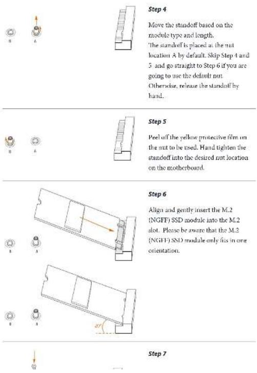
Step 4
Move the standoff based on the module type and length.
The standoff is placed at the nut location A by default. Skip Step 4 and
5 and go straight to Step 6 if you are going to use the default nut.
Otherwise, release the standoff by hand.
Step 5
Peel off the yellow protective film on the nut to be used. Hand tighten the standoff into the desired nut location on the motherboard.
Step 6
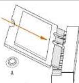
Align and gently insert the M.2
(NGFF) SSD module into the M.2 slot. Please be aware that the M.2
(NGFF) SSD module only fits in one orientation.
Step 7
7390M-STX MXM / B360M-STX MXM
M.2_SSD (NGFF) Module Support List
| Vendor interface P/N | ||
| ADATA SATA3 AXNS381E-128GM-B | ||
| ADATA SATA3 AXNS381E-256GM-B | ||
| ADATA SATA3 ASU800N538-256GT-C | ||
| ADATA SATA3 ASU800N538-512GT-C | ||
| ADATA PCIe3 x4 ASX7000NP-128GT-C | ||
| ADATA PCIe3 x4 ASX8000NP-256GM-C | ||
| ADATA PCIe3 x4 ASX7000NP-256GT-C | ||
| ADATA PCIe3 x4 ASX8000NP-512GM-C | ||
| ADATA PCIe3 x4 ASX7000NP-512GT-C | ||
| Apacer PCIe3 x4 AP240G/280 | ||
| Corsair PCIe3 x4 CSSD-F240GBMP500 | ||
| Crucial SATA3 CT120M5008SD1 | ||
| Crucial SATA3 CT240M5009SD4 | ||
| Intel SATA3 Intel SSDNCKGW080A-001/80G | ||
| Intel PCIe3 x4 SSDPEKKF256G7 | ||
| Intel PCIe3 x4 SSDPUKKF512G7 | ||
| Kingston SATA3 SM228053 | ||
| Kingston PCIe3 x4 SKC1000/480G | ||
| Kingston PCIe3 x4 SH228033/480G | ||
| OCZ PCIe3 x4 RVD400 M2280 512G (NVME) | ||
| PATRIOT PCIe3 x4 PH240GPM280S5DR NVME | ||
| Plector PCIe3 x4 PX 128M8PG | ||
| Plector PCIe3 x4 PX-11M8PG | ||
| Plector PCIe3 x4 PX 256M8PG | ||
| Plector PCIe3 x4 PX-512M8PG | ||
| Plector PCIe PCle PX-G256M6e | ||
| Plector PCIe PX-G512M6e | ||
| Samsung PCIe3 x4 SM961 MZVPW128HFGM (NVMI) | ||
| Samsung PCIe3 x4 PM961 MZV1W1281IIGR (NVMI) | ||
| Samsung PCIe3 x4 960 EVO (MZ-V6E250) (NVME) | ||
| Samsung PCIe3 x4 960 EVO (MZ-V6U250RW) (NVMI) | ||
| Samsung PCIe3 x4 SM951 (NVME) | ||
| Samsung PCIe3 x4 SM951 (MZIIPV2561IDGL) | ||
| Samsung PCIe3 x4 SM951 (MZHPV512HDGL) | ||
| Samsung PCIe3 x4 SM951 (NVME) | ||
| Samsung PCIe3 x4 XP941-512G (MZHPV512HCGL) | ||
| SanDisk PCIe SD6PP4M-128G | ||
| SanDisk PCIe ST6PP4M-256G |
TEAM PCIe3 x4 TM8FP2240G0C101
TEAM PCIe3 x4 TM8FP2480GC110
Transcend SATA3 TS512GMTS600
Transcend SATA3 TS512GMTS800
V Color SATA3 V1.M100.120G 2280B RD
V-Color SATA3 VLM100-240G-2280RGB
V-Color SATA3 VSM100 240G 2280
V-Color SATA3 VLM100-240G-2280B-RD
WD SATA3 WDS100T1B0B 00AS40
WD SATA3 WDS240G1G0B-00RC30
WD PCIe3 x1 WDS256G1X0C 00ENX0 (NVME)
WD PCIe3 x4 WDS512GIX0C-00LNX0 (NVME)
7390M-STX MXM / B360M-STX MXM
2.8 M.2\_SSD (NGFF) Module Installation Guide (M2\_2)
The M.2, also known as the Next Generation Form Factor (NGFF), is a small size and versatile card edge connector that aims to replace mPCIe and mSATA. The Ultra M.2 Socket (M2_2) supports 2242/2260/2280 M.2 PCI Express module up to Gen3 x4 (32 Gb/s).
Installing the M.2_SSD (NGFF) Module
Step 1
Prepare a M.2_SSD (NGFF) module and the screw.
text_image
Technical diagram showing labeled components of a mechanical or electronic component with numbered parts and connection points.Step 2
Depending on the PCB type and length of your M.2_SSD (NGFF) module, find the corresponding not location to be used.
No.123
Nut Location A B C
PCB Length 4.2cm 6cm 8cm
Module Type Type 2242Type2260 Type 2280

Step 3
Move the standoff based on the module type and length.
The standoff is placed at the nut location D by default. Skip Step 3 and 4 and go straight to Step 5 if you are going to use the default nut. Otherwise, release the standoff by hand.
Step 4
Peel off the yellow protective film on the nut to be used. Hand tighten the standoff into the desired nut location on the motherboard.
Step 5
Align and gently insert the M.2 (NGFF) SSD module into the M.2 slot. Please be aware that the M.2 (NGFF) SSD module only fits in one orientation.
7390M-STX MXM / B360M-STX MXM

Step 6
Tighten the screw with a screwdriver to secure the module into place.
Please do not overlighten the screw
as this might damage the module.
M.2_SSD (NGFF) Module Support List
| Vendor Interface PIN | ||
| ADATA SATA3 AXNS581E-128GM-B | ||
| ADATA SATA3 AXNS381E-256GM-B | ||
| ADATA SATA3 ASU800NS38-256GT-C | ||
| ADATA SATA3 ASU800NS38-512GT-C | ||
| ADATA PCIe3 x4 ASX-7000NP-128CT-C | ||
| ADATA PCIe3 x4 ASX8000NP-256GM-C | ||
| ADATA PCIe3 x4 ASX-7000NP-256GT-C | ||
| ADATA PCIe3 x4 ASX8000NP-512GM-C | ||
| ADATA PCIe3 x4 ASX-7000NP-512GT-C | ||
| Apacer PCIe3 x4 AP240G/280 | ||
| Corsair PCIe3 x4 CSSD-F240GBMP500 | ||
| Crucial SATA3 CT120M500SSD4 | ||
| Crucial SATA3 CT240M500SSD4 | ||
| Intel SATA3 Intel SSDSCXGW080A401/80G | ||
| Intel PCIe3 x4 SSDPEKKF256G7 | ||
| Intel PCIe3 x4 SSDPSKKF512G7 | ||
| Kingston SATA3 SM2280S3 | ||
| Kingston PCIe3 x4 SKC1000/180G | ||
| Kingston PCIe2 x4 SI12280S3/480G | ||
| OCZ PCIe3 x4 RVD-000 M2280 512G (NVME) | ||
| PATRIOT PCIe3 x4 PH240GPM280SSDR NVME | ||
| Plexor PCIe3 x4 PX 128M8PpG | ||
| Plexor PCIe3 x4 PX-ITM8PpG | ||
| Plexor PCIe3 x4 PX-256M8PpG | ||
| Plexor PCIe3 x4 PX-512M8PpG | ||
| Plexor PCIe PX-G256M6e | ||
| Plector PCIe PX-G512M6e | ||
| Samsung PCIe3 x4 SM961 KZVPW128HEGM (NVM) | ||
| Samsung PCIe3 x4 PM981 MZV1W128HIGR (NVMI) | ||
| Samsung PCIe3 x4 960 EVO (MZ-V6E250) (NVME) | ||
| Samsung PCIe3 x4 960 LVO (MZ-V6L250BW) (NVMI) | ||
| Samsung PCIe3 x4 SM951 (NVME) | ||
| Samsung PCIe3 x4 SM951 (MZ11PV2561IDGL) | ||
| Samsung PCIe3 x4 SM951 (MZHPV512HDGL) | ||
| Samsung PCIe3 x4 SM951 (NVMI) | ||
| Samsung PCIe3 x4 XP941-512G (MZHPU512HCGL) | ||
| SanDisk PCIe SD6PP4M-128G | ||
| SanDisk PCIe SD6PP4M-256G |
7390M-STX MXM / B360M-STX MXM
TEAM PCIe3 x4 TM8FP2240G0C101
TEAM PCIe3 x4 TM8FP2480GC110
Transcend SATA3 TS256GMTS400
Transcend SATA3 TS512GMTS600
Transcend SATA3 TS512GMTS800
V-Color SATA3 VLM100-120G-2280B-RD
V-Color SATA3 VLM100 240G-2280RGB
V-Color SATA3 VSM100-240G-2280
V Color SATA3 VLM100 240G 2280B RD
WD SATA3 WDS100T1B0B-00AS40
WD SATA3 WDS240G1G0B (XRC30
WD PCIe3 x4 WDS256G1X0C-00LNX0 (NVME)
WD PCIe3 x4 WDS512G1X0C-00ENX0 (NVME)
2.9 Polychrome RGB
Polychrome RGB is a lighting control utility specifically designed for unique individuals with sophisticated tastes to build their own stylish colorful lighting system. Simply by connecting the LED strip, you can customize various lighting schemes and patterns, including Static, Breathing, Strobe, Cycling, Music, Wave and more.
Connecting the LED Strip
Connect your RGB LED strip to the RGB LED Header (RGB_LED1) on the motherboard.
text_image
RGB_LED1 12V3 R B
- Never install the RGB LED cable in the wrong orientation; otherwise, the cable may be damaged.
- Before installing or removing your RGB LED cable, please power off your system and upplung the power cord from the power supply. Failure to do so may cause damages to motherboard components.

- Please note that the RGB LED strip do not come with the package.
- The RGB LED header supports a standard 3650 RGB LED strip (12V/G/R/D), with a maximum power rating of 3A (12V) and length within 2 meters.
7390M-STX MXM / B360M-STX MXM
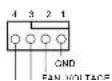
Connecting the Addressable RGB LED Strip (for Z390M-STX MXM only)
Connect your Addressable RGB LED strip to the Addressable LED Header (ADDR LED1) on the motherboard.

text_image
ADDR_LEDI 1 2 3 4 5 6 7 8 9 10 ADD_ADDR VOLT
- Never install the RGB LED cable in the wrong orientation; otherwise, the cable may be damaged.
- Before installing or removing your RGB LED cable, please power off your system and imping the power card from the power supply. Failure to do so may cause damages to motherboard components.

- Please note that the RGB LED strips do not come with the package.
- The RGB LED header supports WS28120 addressable RGB LED strip (5V/Data/GND), with a maximum power rating of 3A (5V) and length within 2 meters.
Chapter 3 Software and Utilities Operation
3.1 Installing Drivers
The Support CD that comes with the motherboard contains necessary drivers and useful utilities that enhance the motherboard's features.
Running The Support CD
To begin using the support CD, insert the CD into your CD-ROM drive. The CD automatically displays the Main Menu if "AUTORUN" is enabled in your computer. If the Main Menu does not appear automatically, locate and double click on the file "ASRSETUP.EXE" in the Support CD to display the menu.
Drivers Menu
The drivers compatible to your system will be auto-detected and listed on the support CD driver page. Please click Install All or follow the order from top to bottom to install those required drivers. Therefore, the drivers you install can work properly.
Utilities Menu
The Utilities Menu shows the application software that the motherboard supports. Click on a specific item then follow the installation wizard to install it.
7390M-STX MXM / B360M-STX MXM
Chapter 4 UEFI SETUP UTILITY
4.1 Introduction
This section explains how to use the UEFI SETUP UTILITY to configure your system. You may run the UEFI SETUP UTILITY by pressing right after you power on the computer, otherwise, the Power On Self Test (POST) will continue with its test routines. If you wish to enter the UEFI SETUP UTILITY after POST, restart the system by pressing

Because the UEFI solution is constantly being updated, the following UEFI setup reveals and descriptions are for reference purpose only, and they may not exactly match what you see on your screen.
4.2 EZ Mode
The EZ Mode screen appears when you enter the BIOS setup program by default. EZ mode is a dashboard which contains multiple readings of the system's current status. You can check the most crucial information of your system, such as CPU speed, DRAM frequency, SATA information, fan speed, etc.
Press <16> or click the 'Advanced Mode' button at the upper right corner of the screen to switch to 'Advanced Mode' for more options.
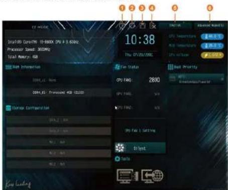
The Advanced Mode provides more options to configure the BIOS settings. Refer to the following sections for the detailed configurations.
To access the EZ Mode, press
4.3.1 UEFI Menu Bar
The top of the screen has a menu bar with the following selections:
| Main | For setting system time/date information |
| OC Tweaker | For overclocking configurations |
| Advanced | For advanced system configurations |
| Tool | Useful tools |
| H/W Monitor | Displays current hardware status |
| Boot | For configuring boot settings and boot priority |
| Security | For security settings |
| Exit | Exit the current screen or the UEFI Setup Utility |
4.3.2 Navigation Keys
Use <←→ key or <→> key to choose among the selections on the menu bar, and use <↑> key or <↓> key to move the cursor up or down to select items, then press
Please check the following table for the descriptions of each navigation key.
| Navigation Key(s) Description | |
| + / - | To change option for the selected items |
| Switch to next function | |
| Go to the previous page | |
| Go to the next page | |
| Go to the top of the screen | |
| Go to the bottom of the screen | |
| To display the General Help Screen | |
| Add / Remove Favorite | |
| Toggle between Easy mode and Advanced mode | |
| Discard changes and exit the SETUP UTILITY | |
| Load optimal default values for all the settings | |
| Save changes and exit the SETUP UTILITY | |
| Print screen | |
| Jump to the Exit Screen or exit the current screen | |
7390M-STX MXM / B360M-STX MXM
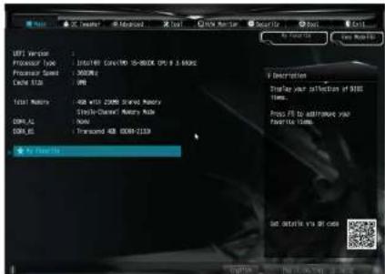
4.4 Main Screen
When you enter the UEFI SETUP UTILITY, the Main screen will appear and display the system overview.
text_image
USE Version Processor Type: 100/149 CONOCO 10-800K CM 8.3.600K Processor Speed: 500MHz Cache SIZE: 1KB Test Motors: USB WITH COMS Grand Motors COMS AI: Mono COMS JL: Transcued USB COMS-2139 By Start Us Description Display your offset of BIOS times. Press FIS to address your favorite 100ms. Set detail you at caseFavorite
Display your collection of BIOS items. Press F5 to add/remove your favorite items.
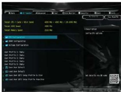
4.5 OC Tweaker Screen
In the OC Tweaker screen, you can set up overclocking features.
text_image
Target 0% / Cache / USB Speed Target 10% Speed Target Recovery Speed USB Format USB Configuration Voltage Configuration User Profile 1: Default User Profile 2: Default User Profile 3: Default User Profile 4: Default Load User Default Load User IGBT Setup Profile to 3.0kV Load User IGBT Setup Profile to 3.0kV Get down to via QR code
because the LETH software is constantly being updated, the following LETH setup screen and descriptions are for reference purpose only, and they may not exactly match what you see on your screen.
CPU Configuration
Boot Performance Mode
Default is Max Non-Turbo performance mode. It will keep cpu Flex ratio till OS handoff. Max Battery mode will set CPU ratio as x8 till OS handoff. This option is suggested for BCLK overclocking.
FCLK Frequency
Configure the PCI.K Frequency.
AVX Ratio Offset
Z390M-STX MXM / B360M-STX MXM
BCLK Aware Adaptive Voltage
BCLK Aware Adaptive Voltage enable/disable. When enabled, pcode will be aware
of the BCLK frequency when calculating the CPU V/F curves. This is ideal for
BCLK OC to avoid high voltage overrides.
Ring to Core Ratio Offset
Disable Ring to Core Ratio Offset so the ring and core can run at the same
frequency
Intel SpeedStep Technology
Intel SpeedStep technology allows processors to switch between multiple frequencies and voltage points for better power saving and heat dissipation.
Intel Turbo Boost Technology
Intel Turbo Boost Technology enables the processor to run above its base operating
frequency when the operating system requests the highest performance state.
Intel Speed Shift Technology
Enable/Disable Intel Speed Shift Technology support. Enabling will expose the
CPPC v2 interface to allow for hardware controlled P-sates.
Long Duration Power Limit
Configure Package Power Limit 1 in walls. When the limit is exceeded, the CPU
ratio will be lowered after a period of time. A lower limit can protect the CPU and
save power, while a higher limit may improve performance.
Long Duration Maintained
Configure the period of time until the CPU ratio is lowered when the Long
Duration Power Limit is exceeded.
Short Duration Power Limit
Configure Package Power Limit 2 in walls. When the limit is exceeded, the CPU
ratio will be lowered immediately. A lower limit can protect the CPU and save
power, while a higher limit may improve performance.
CPU Core Current Limit
GT Current Limit
Configure the current limit of the GT slice. A lower limit can protect the CPU and save power, while a higher limit may improve performance.
GT Frequency
Configure the frequency of the integrated GPU.
DRAM Configuration
DRAM Tweaker
Fine tune the DRAM settings by leaving marks in checkboxes. Click OK to confirm and apply your new settings.
DRAM Timing Configuration
Load XMP Setting
Load XMP settings to overclock the memory and perform beyond standard specifications.
DRAM Reference Clock
Select Auto for optimized settings.
DRAM Frequency
If [Auto] is selected, the motherboard will detect the memory module(s) inserted and assign the appropriate frequency automatically.
Primary Timing
CAS# Latency (tCL)
The time between sending a column address to the memory and the beginning of the data in response.
RAS# to CAS# Delay and Row Precharge (tRCDtRP)
RAS# to CAS# Delay: The number of clock cycles required between the opening of a row of memory and accessing columns within it.
Row Precharge: The number of clock cycles required between the issuing of the precharge command and opening the next row.
Z390M-STX MXM / B360M-STX MXM
Command Rate (CR)
The delay between when a memory chip is selected and when the first active command can be issued.
Secondary Timing
Write Recovery Time (tWR)
The amount of delay that must elapse after the completion of a valid write operation, before an active bank can be precharged.
Refresh Cycle Time (tRFC)
The number of clocks from a Refresh command until the first Activate command to the same rank.
RAS to RAS Delay (tRRD\_L)
The number of clocks between two rows activated in different banks of the same rank.
RAS to RAS Delay (tRRD\_S)
The number of clocks between two rows activated in different banks of the same rank.
Write to Read Delay (tWTR\_L)
The number of clocks between the last valid write operation and the next read command to the same internal bank.
Write to Read Delay (tWTR\_S)
The number of clocks between the last valid write operation and the next read command to the same internal bank.
Read to Precharge (tRTP)
The number of clocks that are inserted between a read command to a row pre-charge command to the same rank.
Four Activate Window (tFAW)
The time window in which four activates are allowed the same rank.
Third Timing
tREFI
Configure refresh cycles at an average periodic interval.
tCKE
Configure the period of time the DDR4 initiates a minimum of one refresh command internally once it enters Self Refresh mode.
Turn Around Timing
tRDRD_sg
Configure between module read to read delay.
tRDRD_dg
Configure between module read to read delay.
tRDRD_dr
Configure between module read to read delay.
tRDRD_dd
Configure between module read to read delay.
tRDWR_sg
Configure between module read to write delay.
tRDWR_dg
Configure between module read to write delay.
tRDWR_dr
Configure between module read to write delay.
tRDWR_dd
Configure between module read to write delay.
tWRRD_sg
Configure between module write to read delay.
Z390M-STX MXM / B360M-STX MXM
tWRRD_dr
Configure between module write to read delay.
tWRRD_dd
Configure between module write to read delay.
tWRWR_sg
Configure between module write to write delay.
tWRWR_dg
Configure between module write to write delay.
tWRWR_dr
Configure between module write to write delay.
tWRWR_dd
Configure between module write to write delay.
Round Trip Timing
RTL Init Value
Configure round trip latency init value for round trip latency training.
IOL Init Value
Configure IO latency init value for IO latency training.
RTL (CH A)
Configure round trip latency for channel A.
RTL (CH B)
Configure round trip latency for channel B.
IO-L (CHA)
Configure IO latency for channel A.
IO-L (CH B)
e. = _1 ; = 1 ;
IOL Offset (CH B)
Configure IO latency offset for channel B.
RFR Delay (CH A)
Configure RFR Delay for Channel A.
RFR Delay (CH B)
Configure RFR Delay for Channel B.
ODT Setting
ODT WR (A1)
Configure the memory on die termination resistors' WR for channel A1.
ODT WR (B1)
Configure the memory on die termination resistors' WR for channel B1.
ODT NOM (A1)
Use this to change ODT (CH A1) Auto/Manual settings. The default is [Auto].
ODT NOM (B1)
Use this to change ODT (CH BI) Auto/Manual settings. The default is [Auto].
ODT PARK (A1)
Configure the memory on die termination resistors' PARK for channel A1.
ODT PARK (B1)
Configure the memory on die termination resistors' PARK for channel B1.
COMP Setting
RCOMP2-CMD/CTI Ron (Drive Strength)
Z390M-STX MXM / B360M-STX MXM
DQ Driving
Adjust DQ Driving for better signal. Default is 26.
Command Driving
Adjust Command Driving for better signal. Default is 20.
Control Driving
Adjust Control Driving for better signal. Default is 20.
Clock Driving
Adjust Clock Driving for better signal. Default is 26.
MRS Setting
MRS tCL
Configure the ICL for Memory MRS MR0.
MRS tWRtRTP
Configure the IWRITP for Memory MRS MRC.
MRS tCWL
Configure the tCWL for Memory MRS MR2.
MRS tCCD\_L
Configure the tCL for Memory MRS MR6.
Advanced Setting
Timing Optimization
Configure the fast path through the MRC.
Realtime Memory Timing
Configure the realtime memory timings.
[Enabled] The system will allow performing realtime memory timing changes after MRC_DONE.
Command Tristate
e = d e 1907.4.
Reset On Training Fail
Reset system if the MRC training fails.
MRC Fast Boot
Enable Memory Fast Boot to skip DRAM memory training for booting faster.
Voltage Configuration
CPU Core/Cache Voltage
Configure the voltage for the CPU Core/Cache.
CPU Load-Line Calibration
CPU Load Line Calibration helps prevent CPU voltage droop when the system is under heavy load.
DRAM Voltage
Use this to configure DRAM Voltage. The default value is [Auto].
PCH +1.0 Voltage
Configure the chipset voltage (1.0V).
VCCST Voltage
Configure the voltage for the VCCST.
VCCSA Voltage
Configure the voltage for the VCCSA.
Save User Default
Type a profile name and press enter to save your settings as user default.
Load User Default
Load previously saved user defaults.
Save User UEFI Setup Profile to Disk
Save current UEFI settings as an user default profile to disk.
Load User UEFI Setup Profile to Disk
7390M-STX MXM / B360M-STX MXM
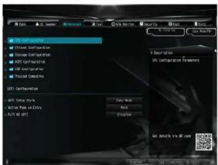
4.6 Advanced Screen
In this section, you may set the configurations for the following items: CPU
Configuration, Chipset Configuration, Storage Configuration, ACPI Configuration,
USB Configuration and Trusted Computing..
text_image
MFT Configuration Direct Configuration Storage Configuration MFS Configuration DB Configuration Fixed Connection MFT Configuration MFT Setup Style Active Path on Entry Full 40 (F1) Case Note Auto Unloaded Set details via @ case
Setting wrong values in this section may cause the system to malfunction.
UEFI Configuration
UEFI Setup Style
Select the default mode when entering the UEFI setup utility.
Active Page on Entry
Select the default page when entering the UEFI setup utility.
Full HD UEFI
When |Auto| is selected, the resolution will be set to 1920 x 1080 if the monitor supports Full HD resolution. If the monitor does not support Full HD resolution,
4.6.1 CPU Configuration

text_image
MOSLED/DFS Control/OS USB/IO System (10-800K PS) 1:300Ps Microcontroller CPU Speed CPU Speed Processor Name: Select Processor Name: CPU C States Asport On Ethernet Advertising On Virtualization Technology Network Provider Internet Cards Use Protocol Software Systems Extensions 6000 Description Select the number of cores to enable it each processor packet Get onto it via Web OKIntel Hyper Threading Technology
Intel Hyper Threading Technology allows multiple threads to run on each core, so that the overall performance on threaded software is improved.
Active Processor Cores
Select the number of cores to enable in each processor package.
CPU C States Support
Enable CPU C States Support for power saving. It is recommended to keep C3, C6 and C7 all enabled for better power saving.
CPU Thermal Throttling
Enable CPU internal thermal control mechanisms to keep the CPU from overheating.
Intel Virtualization Technology
Intel Virtualization Technology allows a platform to run multiple operating systems
Z390M-STX MXM / B360M-STX MXM
Hardware Prefetcher
Automatically prefetch data and code for the processor. Enable for better performance.
Adjacent Cache Line Prefetch
Automatically prefetch the subsequent cache line while retrieving the currently requested cache line. Enable for better performance.
Software Guard Extensions (SGX)
Use this item to enable or disable Software Controlled Software Guard Extensions (SGX).
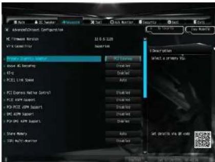
4.6.2 Chipset Configuration
text_image
Advanced/Close Configuration PC Firmware Version 12.0-5.000 PC Security Description Select a primary UI PC Express Network Control PC ARM Support PC PEE ARM Support PC OPE ARM Support Store Memory DCI Multi-OperatorPrimary Graphics Adapter
Select a primary VGA.
Above 4G Decoding
Enable or disable 64-bit capable Devices to be decoded in Above 4G Address Space (only if the system supports 64 bit PCI decoding).
VT-d
Intel® Virtualization Technology for Directed I/O helps your virtual machine monitor better utilize hardware by improving application compatibility and reliability, and providing additional levels of manageability, security, isolation, and I/O performance.
PCIE1 Link Speed
Select the link speed for PCIe1.
PCI Express Native Control
Select Enable for enhanced PCI Express power saving in OS.
7390M-STX MXM / B360M-STX MXM
DMI ASPM Support
This option enables/disables the control of ASPM on CPU side of the DMI Link.
PCH DMI ASPM Support
This option enables/disables the ASPM support for all PCH DMI devices.
Share Memory
Configure the size of memory that is allocated to the integrated graphics processor when the system boots up.
IGPU Multi-Monitor
Select disable to disable the integrated graphics when an external graphics card is installed. Select enable to keep the integrated graphics enabled at all times.
Inte(R) Ethernet Connection I219-V
Enable or disable the onboard network interface controller (Intel® 1219V).
Onboard HD Audio
Enable/disable onboard IID audio. Set to Auto to enable onboard IID audio and automatically disable it when a sound card is installed.
Onboard HDMI HD Audio
Enable/disable onboard HDMI HID audio. Set to Auto to enable onboard HID audio and automatically disable it when a sound card is installed.
MXM Display Hardware IDs
Select among different MXM Display Hardware IDs.
Virtual Battery Control
Configure the virtual battery control.
Onboard WAN Device
Enable/disable the onboard WAN device.
WAN Radio
Enable/disable the WiFi module's connectivity.
Deep Sleep
Configure deep sleep mode for power saving when the computer is shut down.
Restore on AC/Power Loss
Select the power state after a power failure. If [Power Off] is selected, the power will remain off when the power recovers. If [Power On] is selected, the system will start to boot up when the power recovers.
7390M-STX MXM / B360M-STX MXM
4.6.3 Storage Configuration

text_image
Advanced Storage Management SATA 1.0 (T) SATA Model Selected SATA Expressive Link Power Management Next Step 5.9.4.3.7 NAT.1 NAT.2 N2.1 N2.2 N2.3 Not Detected Not Detected Not Detected Not Detected Not Detected End End End Description End: NATA 1.0 (T) End: End Set details via all dataSATA Controller(s)
Enable/disable the SATA controllers.
SATA Controller Speed
Indicates the maximum speed the SATA controller can support
SATA Mode Selection
[AHCI] Supports new features that improve performance.
[Intel RST Premium (RAID)] Combine multiple disk drives into a logical unit.
SATA Aggressive Link Power Management
SATA Aggressive Link Power Management allows SATA devices to enter a low power state during periods of inactivity to save power. It is only supported by AHCI mode.
Hard Disk S.M.A.R.T.
4.6.4 ACPI Configuration

text_image
Advanced iOS Configuration Advanced iOS 100% 100% Power 100% 100% Power 100% 100% Power 100% 100% Power Description It is recommended to select auto for iOS 3D power settings Get shot by: are off codeSuspend to RAM
Select disable for ACPI suspend type S1. It is recommended to select auto for ACPI S3 power saving.
1219 LAN Power On
Allow the system to be waked up by 1219 LAN.
RTC Alarm Power On
Allow the system to be waked up by the real time clock alarm. Set it to By OS to let it be handled by your operating system.
USB Keyboard/Remote Power On
Allow the system to be waked up by an USB keyboard or remote controller.
USB Mouse Power On
Allow the system to be waked up by an USB mouse.
7390M-STX MXM / B360M-STX MXM
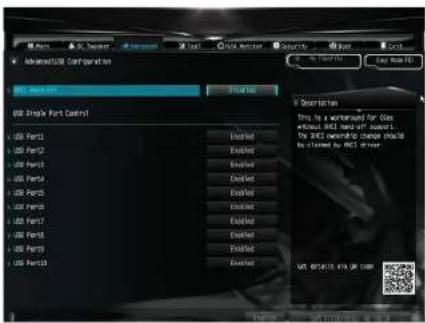
4.6.5 USB Configuration
text_image
Advanced/IG Configuration USB Start-Off USB Simple Port Control USB Port1 USB Port2 USB Port3 USB Port4 USB Port5 USB Port6 USB Port7 USB Port8 USB Port9 USB Port10 USB Port11 USB Port12 USB Port13 USB Port14 USB Port15 USB Port16 USB Port17 USB Port18 USB Port19 USB Port20 USB Port21 USB Port22 USB Port23 USB Port24 USB Port25 USB Port26 USB Port27 USB Port28 USB Port29 USB Port30 USB Port31 USB Port32 USB Port33 USB Port34 USB Port35 USB Port36 USB Port37 USB Port38 USB Port39 USB Port40 USB Port41 USB Port42 USB Port43 USB Port44 USB Port45 USB Port46 USB Port47 USB Port48 USB Port49 USB Port50 USB Port51 USB Port52 USB Port53 USB Port54 USB Port55 USB Port56 USB Port57 USB Port58 USB Port59 USB Port60 USB Port61 USB Port62 USB Port63 USB Port64 USB Port65 USB Port66 USB Port67 USB Port68 USB Port69 USB Port70 USB Port71 USB Port72 USB Port73 USB Port74 USB Port75 USB Port76 USB Port77 USB Port78 USB Port79 USB Port80 USB Port81 USB Port82 USB Port83 USB Port84 USB Port85 USB Port86 USB Port87 USB Port88 USB Port89 USB Port90 USB Port91 USB Port92 USB Port93 USB Port94 USB Port95 USB Port96 USB Port97 USB Port98 USB Port99 USB Port100XHCI Hand-off
This is a workaround for OSes without XHCI hand-off support. The XHCI ownership change should be claimed by XHCI driver.
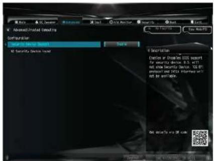
4.6.6 Trusted Computing
text_image
Advanced/Installed Security Configuration Driver Of Device Support Only Security Devices Model Secretion Explorer in Displayless SSDS support for security device, 8.5 x 61T set new Security Device, 100% protection and NLSA software with NLSA software. Get details via USB codeSecurity Device Support
Enable or disable BIOS support for security device.
7390M-STX MXM / B360M-STX MXM
4.7 Tools

text_image
MIFI Task Service 100 Security Drive Tool MIFI Update Activity Instant Fool Internet User - MIFI 463.91.44 Network Configuration I Description Contact Black Tech Service if you are saving trouble with your 26. Please save Black configuration before using MIFI Task Service Set details via @ careUEFI Tech Service
Contact ASRock Tech Service if you are having trouble with your PC. Please setup network configuration before using UETI Tech Service.
SSD Secure Erase Tool
Use this tool to securely erase SSD.
Instant Flash
Save CEPI files in your USB storage device and run Instant Flash to update your CEPI.
Internet Flash - DHCP (Auto IP), Auto
ASRock Internet Flash downloads and updates the latest UEFI firmware version from our servers for you. Please setup network configuration before using Internet Flash.
*For BIOS backup and recovery purpose, it is recommended to plug in your USB pen drive before using this function.
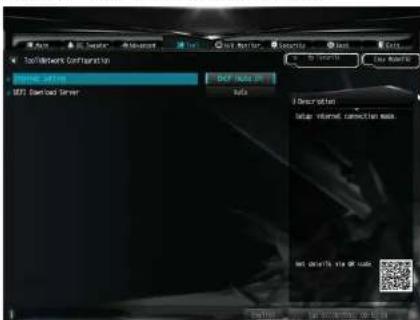
Network Configuration
Use this to configure internet connection settings for Internet Flash.
text_image
Tool/Wire Connection Import Setting NET Download Server NET DOWNLOAD MACS Description: data: internal connection mask Net download via or clickInternet Setting
Enable or disable sound effects in the setup utility.
UEFI Download Server
Select a server to download the UEFI firmware.
7390M-STX MXM / B360M-STX MXM
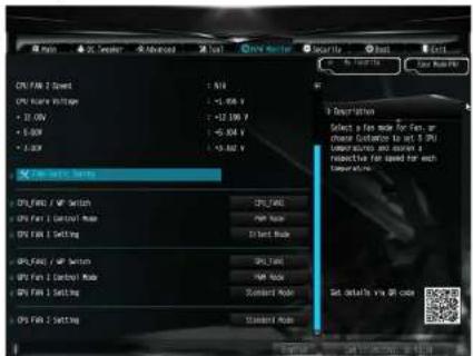
4.8 Hardware Health Event Monitoring Screen
This section allows you to monitor the status of the hardware on your system, including the parameters of the CPU temperature, motherboard temperature, fan speed and voltage.
text_image
CPU FX 2 Select CPU FX 30000000000000000000000000000000000000000000000000000000000000000000000000000000000000 CPU FX 2 Setting CPU FX 31.564 x CPU FX 31.564 x CPU FX 31.564 x CPU FX 31.564 x CPU FX 31.564 x CPU FX 31.564 x CPU FX 31.564 x CPU FX 31.564 x CPU FX 31.564 x CPU FX 31.564 xFan-Tastic Tuning
Select a fan mode for CPU Fans 1&2, or choose Customize to set 5 CPU temperatures and assign a respective fan speed for each temperature.
CPU Fan1 / WP Switch
Select CPU or Water Pump mode.
CPU Fan 1 Control Mode
Select PWM mode or DC mode for CPU_FAN1.
GPU Fan 1 Setting
Select a fan mode for GPU_FAN1, or choose Customize to set 5 GPU temperatures and assign a respective fan speed for each temperature.
GPU Fan1 / WP Switch
GPU Fan1 Setting
Select a fan mode for GPU_FAN1, or choose Customize to set 5 GPU temperatures and assign a respective fan speed for each temperature.
CPU Fan 2 Setting
Select a fan mode for CPU Fan 2, or choose Customize to set 5 CPU temperatures and assign a respective fan speed for each temperature.
7390M-STX MXM / B360M-STX MXM
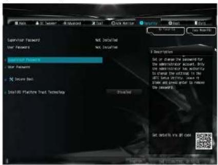
4.9 Security Screen
In this section you may set or change the supervisor/user password for the system. You may also clear the user password.
text_image
Monitor Password User Features Monitor Password User Features X Source Back Dial400 Platform Drive Technologies Not installed Not installed Description Set or change the password for the administrator account. Only the administrator has additional to change the setting. In the AND feature window, one is Show and press after to remove the password. This file Set details via all codeSupervisor Password
Set or change the password for the administrator account. Only the administrator has authority to change the settings in the UEFI Setup Utility. Leave it blank and press enter to remove the password.
User Password
Set or change the password for the user account. Users are unable to change the settings in the UEFI Setup Utility. Leave it blank and press enter to remove the password.
Secure Boot
Use this item to enable or disable support for Secure Boot.
Intel(R) Platform Trust Technology
Enable/disable Intel PTT in ME. Disable this option to use discrete TPM Module.
4.10 Boot Screen
This section displays the available devices on your system for you to configure the boot settings and the boot priority.

text_image
Auto Data Properties Fast Back Auto From Object LM Auto Project Trace Auto Non-Link Auto SR Disable Auto Failure Board Message COM Accessibility Support Model Description Data the system best order get available via codeFast Boot
Past Boot minimizes your computer's boot time. In fast mode you may not boot from an USB storage device. The VBIOS must support UEFI GOP if you are using an external graphics card. Please notice that Ultra Fast mode will boot so fast that the only way to enter this UEFI Setup Utility is to Clear CMOS or run the Restart to UEFI utility in Windows.
Boot From Onboard LAN
Allow the system to be waked up by the onboard LAN.
Setup Prompt Timeout
Configure the number of seconds to wait for the setup hot key.
Bootup Num-Lock
Select whether Num Lock should be turned on or off when the system boots up.
7390M-STX MXM / B360M-STX MXM
Boot Failure Guard Message
If the computer fails to boot for a number of times the system automatically restores the default settings.
CSM (Compatibility Support Module)
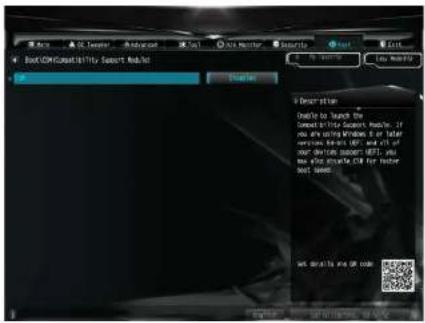
text_image
BootCOM Sensitivity Support Model Description Enable to launch the Connect to the Smart Model, if you are using Windows 8 or similar versiones: Web-Net (WP) and Web of User's daily support (DF), you you also use Windows for better bad sense. Get details to our codeCSM
I unable to launch the Compatibility Support Module. Please do not disable unless you're running a WHCK test.
4.11 Exit Screen

text_image
Disk Drive and Ctrl Disk Drive and Ctrl Disk Drive Disk RFS Defaults Disk RFS Default Disk RFS Default from filepath device Disk Default RFS: Regularized/defauler 2.01.00 - Partition 1 Description Disk system status after saving the channels. 100 key can be used for this service line Set default via All codeSave Changes and Exit
When you select this option the following message, "Save configuration changes and exit setup?" will pop out. Select [OK] to save changes and exit the UEFI SETUP UTILITY.
Discard Changes and Exit
When you select this option the following message, "Discard changes and exit setup?" will pop out. Select [OK] to exit the UEFI SETUP UTILITY without saving any changes.
Discard Changes
When you select this option the following message, "Discard changes?" will pop out. Select [OK] to discard all changes.
Load UEFI Defaults
Load UEFI default values for all options. The F9 key can be used for this operation.
Launch EFI Shell from filesystem device