IBF 25-1 - Grass trimmer IKRA - Free user manual and instructions
Find the device manual for free IBF 25-1 IKRA in PDF.

User questions about IBF 25-1 IKRA
0 question about this device. Answer the ones you know or ask your own.
Ask a new question about this device
Download the instructions for your Grass trimmer in PDF format for free! Find your manual IBF 25-1 - IKRA and take your electronic device back in hand. On this page are published all the documents necessary for the use of your device. IBF 25-1 by IKRA.
USER MANUAL IBF 25-1 IKRA
Operating Instructions - Translation of the original Operating Instructions
Read operating instructions before use!
FR
text_image
Technical diagram of a handheld device with numbered parts, including a spray gun and mechanical components.GB - List of components
- Cord cutting head
- Cutting cord
- Protective shield for metal blade
- Cutting blade
- Protective shield for cutting cord
- Shaft
- Shaft coupling
- Handle
- Throttle lever
- Ignition switch
- Locking lever
-
Locking button
-
Air filter housing
- Starter handle
- Silencer cover
- Fuel pump
- Choke
- Starter housing
- Fuel tank
- Fastening eye for carry strap
- Carry belt
- Optional: Oil/petrol mixing bottle
- Optional: Tool
natural_image
Close-up of hands using a sewing machine to adjust or install a black mechanical component (no visible text or symbols)
natural_image
Close-up of hands assembling or adjusting a mechanical component (no visible text or symbols)
natural_image
Close-up of a hand operating a mechanical component with a bolted joint (no visible text or symbols)
natural_image
Close-up of hands adjusting a mechanical component with a bolt (no visible text or symbols)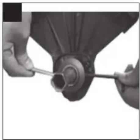
natural_image
Close-up of hands using a tool to adjust or install a mechanical component (no visible text or symbols)
natural_image
Close-up of hands assembling a mechanical component (no visible text or symbols)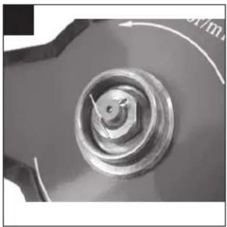
natural_image
Close-up of a metallic mechanical component with a central hub and circular base, no visible text or symbols.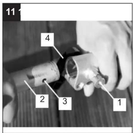
text_image
11 4 2 3 1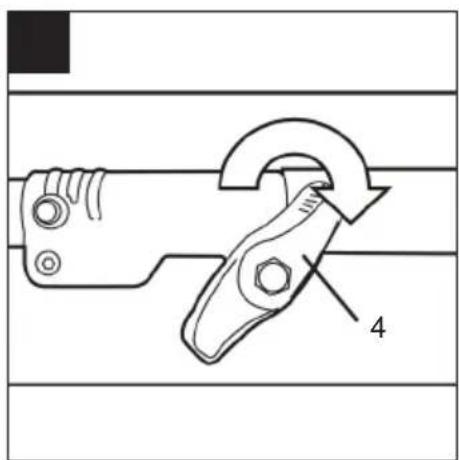
text_image
Technical diagram showing a mechanical clamp or tool with labeled component '4'
natural_image
Line drawing of a person wearing a short-sleeve shirt and belt, carrying a black bandage (no text or symbols)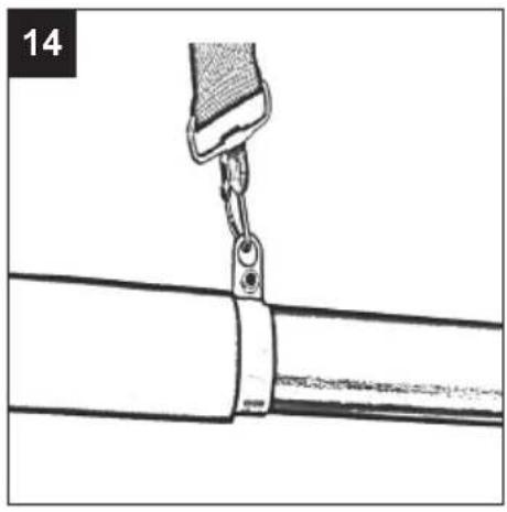
natural_image
Diagram of a cable fastening or mounting assembly with a clamp securing a cable (no text or symbols present)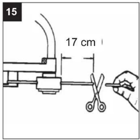
text_image
15 17 cm
text_image
16 STOP
text_image
17 Start Run
natural_image
Close-up of a mechanical device with labeled component 'A' (no visible text or symbols beyond label)
text_image
19 12 11 9
natural_image
Close-up of a mechanical device with labeled component '13' and number '20' (no readable text or symbols beyond labels)
text_image
21 Start Run
text_image
22 STOP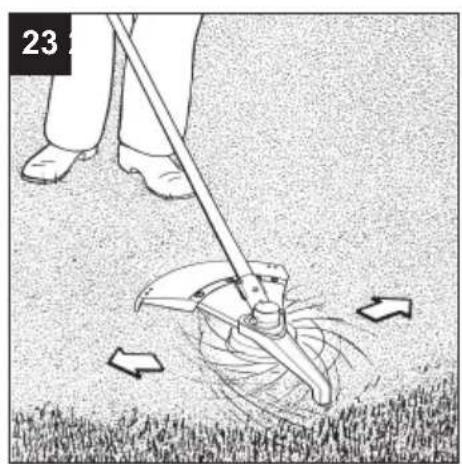
natural_image
Person using a mop to clean grass with arrows indicating motion (no text or symbols)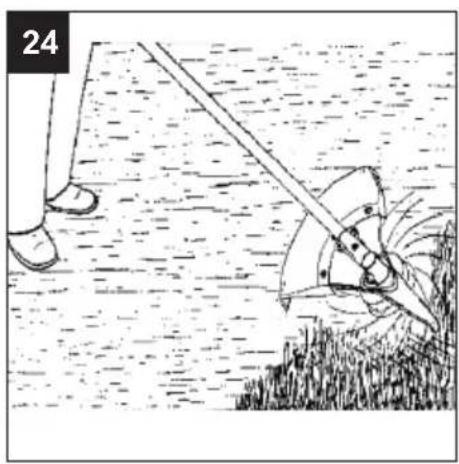
natural_image
Illustration of a person using a manual power saw to lift or spread a surface, with no visible text or symbols.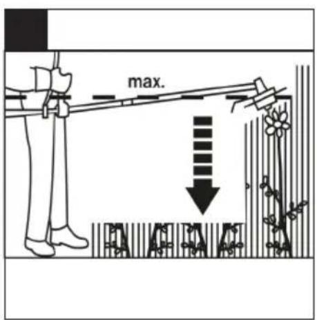
text_image
max.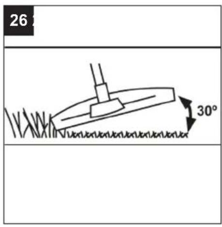
text_image
26 30°
natural_image
Illustration of a person using a lamp with a magnifying glass, surrounded by a grid pattern (no text or symbols)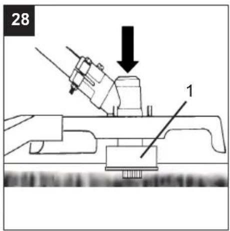
text_image
28 1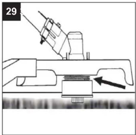
natural_image
Mechanical assembly diagram showing a tool interacting with a mechanical component (no text or symbols visible)
natural_image
Close-up of hands holding a black mechanical component (no visible text or symbols)
natural_image
Hand holding a black plastic component with wires, no visible text or symbols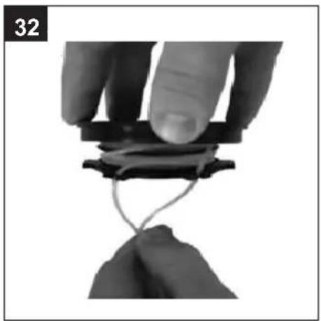
natural_image
Close-up of hands holding a thin wire or wire on a mechanical component (no text or symbols visible)
natural_image
Close-up of a hand holding wires connecting a black circular component (no text or symbols visible)
natural_image
Close-up of hands holding a black mechanical component with wires wrapped around it (no visible text or symbols)
natural_image
Close-up of a hand holding a black mechanical component, no visible text or symbols
natural_image
Close-up of hands using a power tool on a mechanical device (no visible text or symbols)
natural_image
Two views of a device housing: one open showing internal components, the other closed with a dark square (no text or symbols visible)
natural_image
Close-up of a hand holding a small mechanical component with a curved handle (no visible text or symbols)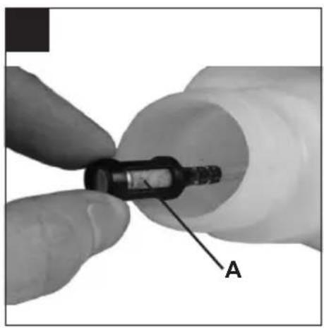
natural_image
Close-up of a finger inserting a small black component into a white cylindrical tube, labeled 'A' (no text or symbols on the object itself)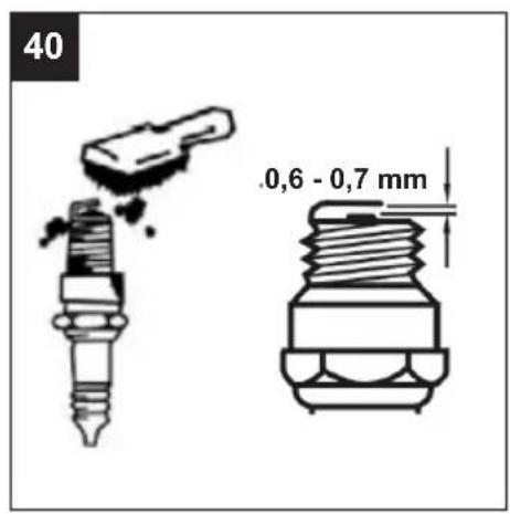
text_image
40 .0,6 - 0,7 mm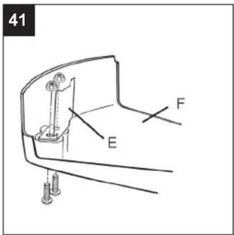
text_image
41 E Ftext_image
max. 500ml Petrol/oil mixture with a ratio of 40:1Gemischtank

$$ a = \text { Aus / Off } $$
GB | Operating Instruction
CONTENTS
Page
LIST OF COMPONENTS 1 - 2
PICTURES 3 - 6
INTENDED USE GB-1
EXPLANATION OF THE INFORMATION PLACARD ON THE DEVICE GB-2-3
RATINGS GB-4
SAFETY REQUIREMENTS GB-5
SCOPE OF DELIVERABLES GB-6
BEFORE COMMISSIONING GB-6
FUEL AND OIL GB-7
STARTING THE ENGINE GB-8
EC DECLARATION OF CONFORMITY
SERVICE
INTENDED USE
The device is intended for cutting lawns and grass areas. The observance of the manufacturer's operating instructions included is a prerequisite for the proper use of the device. Any other use that is not expressly permitted in these instructions can lead to the device being damaged and a serious risk for the operator. Observe the restrictions in the safety instructions. Please note that our device has not been designed with the intention of it being used for commercial, trade or industrial applications. We accept no liability if the device is used in commercial, trade or industrial operations or corresponding activities.
Attention! Due to bodily endangerment of the operator the following work must not be undertaken with the motor scythe: Clearing pathways and as a chipper for shredding tree and hedge cuttings. Furthermore, the motor scythe must not be used for levelling bumps in the ground such as mole hills for example. For safety reasons the motor scythe must not be used as a drive unit for other tools or tool sets of any type. The machine must only be used for its intended purpose. Any other use shall be considered improper use. The user/operator, and not the manufacturer, is responsible for any damage or injuries arising from this.
GB | Operating Instruction
Explanation of the information placard on the device

1

2

3

4

5

6

7

8

9

10

11

12

13

14

15

16

17

18


19
-
Warning!
-
Read the operating instructions before use!
-
Wear eye/head protection and hearing protection!
-
Wear sturdy footwear!
-
Wear protective gloves!
-
The distance between the machine and bystanders must be at least 15 m!
-
Watch out for objects being ejected at high speed.
-
Fire hazard! The fuel is flammable and therefore may not be spilled. Do not work next to open flames. Do not smoke. Only refill fuel when the motor is cool and is not running.
-
Maximum cutting device speed. Only use suitable cutting devices.
-
Not approved for use of saw blades
-
DANGER OF INJURY! Warning! Do not put hands under the cover of the machine when it is running. Caution! Rotating electrical too!
-
ATTENTION: HOT SURFACE
-
Guaranteed acoustic capacity level L_WA
-
Danger of flying objects!
-
Keep third parties out of the area of risk.
-
Push the fuel pump 6 times
-
Petrol and oil are flammable and may explode. Fires, naked flames and smoking are prohibited.
-
Confirms the conformity of the power tool with the directives of the European Community.
-
Beware of blade thrust. When using metal cutting tools (thicket blade) there is the danger of kickbacks if the tool gets in touch with some solid object.
GB | Operating Instruction
EXPLANATORY SYMBOLS ON THE MACHINE (if present)

text_image
max. 500ml Petrol/oil mixture with a ratio of 40:1Fuel tank

Engine stop switch positions
a = stop/Off
b = run/On

Choke

Primer
EXPLANATORY SYMBOLS ON THE PROTECTION DEVICES (if present)

Cutting device rotation direction
Petrol brushcutter
RATINGS
Model HBFI 75-1 Hurricane
| Engine output kW 0,8 | ||
| Engine type 2-stroke | ||
| Cubic capacity cm3 25 | ||
| Fuel lubricated petrol 40:1 | ||
| Tank volume ml 500 | ||
| Idling speed min-1 3000 | ||
| Maximum engine speed min -1 10500 | ||
| Max. speed of the cutting tool min -1 8500 | ||
| Fuel consumption kg/h 0,38 | ||
| Cutting diameter cm 43 (Blade = 23) | ||
| Cord diameter mm 2,0 | ||
| Overall cord length m 2 x 3,0 | ||
| Cord extension Tap'n go | ||
| Weight kg 6,5 | ||
| Noise level dB (A) 97,4 [K 3,0 dB(A)] | ||
| Vibration – racing m/s2 9,839 [K 1,5 m/s2] | ||
| Vibration – idling m/s2 3,192 [K 1,5 m/s2] |
Technical changes reserved.
The devices are manufactured in accordance with the provisions of DIN EN ISO 11806 and fully comply with the provisions of the German Product Safety Act.
Notice: The vibration value indicated was determined with a standardized tool and can be used to make comparisons with other petrol equipment as well as temporary estimates of the load through the vibrations.
WARNING! The vibration value may vary according to the usage of the machine and its fitted equipment, and be higher than the one indicated. Safety measures must be established to protect the user and must be based on the load estimate generated by the vibrations in real usage conditions. In this regard, all the operational cycle phases must be taken into consideration, such as switching off or idle running.
WARNING: This machine's starter unit generates an average sized electromagnetic field, but it is not however possible to exclude the possibility of interference on any active or passive medical devices that operators may be wearing; this could be risky for their health conditions. All those using medical devices should always consult their GP, or the device manufacturer, before using this machine.
WARNING: Prolonged exposure to vibrations can cause injuries and neurovascular disorders (also called "Renaud's syndrome" or "white hand"), especially to people suffering from circulation disorders. The symptoms can regard the hands, wrists and fingers and are shown through loss of sensitivity, torpor, itching, pain and discolouring of or structural changes to the skin. These effects can be worsened by low ambient temperatures and/or by gripping the handgrips excessively tightly. If the symptoms occur, the length of time the machine is used must be reduced and a doctor consulted.
When working with the device, a certain level of noise cannot be avoided. Noisy work should be scheduled for hours, during which it is allowed by statute or other local regulations. Adhere to any applicable rest times and limit your working time to the necessary minimum time. For your personal protection and the protection of people nearby, suitable hearing protection must be worn.
Noise emission information in accordance with the German Product Safety Act (ProdSG) and the EC Machine Directive: the noise pressure level at the place of work can exceed 80 dB(A). In such cases the operator will require noise protection (e.g. wearing of ear protectors).
⚠️Please do also consider any local regulations concerning noise protection!
GB | Operating Instruction
SAFETY REQUIREMENTS
A) TRAINING
1) Read the instructions carefully. Become acquainted with the controls and the proper use of the machine. Learn how to stop the engine quickly.
2) Only use the machine for the purpose for which it was designed, namely
- cutting grass and non-woody vegetation, using a nylon line (e.g. around the edges of lawns, flowerbeds, walls, fences and small grassy areas to tidy up the cutting done using a mower);
-cutting tall grass, dry branches, twigs and woody shrubs of up to 2 cm diameter, with the help of metal or plastic blades.
-Any other use may be dangerous and damage the machine.
-Examples of improper use may include, but are not limited to:
-use the machine for sweeping;
-trimming hedges or other jobs in which the cutting device is not used on ground level;
-pruning trees;
-using the machine with the cutting device above the operator's belt level;
-using the machine for cutting non-plant material;
-use of the machine by more than one person
3) Never allow children or persons unfamiliar with
- these instructions to use the machine. Local regulations
- can restrict the age of the user.
4) The machine must never be used by more than one person.
5) Never use the machine:
-when people, especially children or pets are in the vicinity;
-if the user is tired or unwell, or has taken medicine, drugs, alcohol or any substances which may slow his reflexes and compromise his judgement;
-if the user is not capable of holding the machine firmly with two hands and/or remaining standing on the ground whilst working.
6) Keep in mind that the operator or user is responsible for accidents or hazards occurring to other people or their property.
B) PREPARATION
1) Always wear adequate clothing which does not -hamper movements when using the machine.
- Always wear slim-fitting protective clothing, fitted with shear-proof protection devices.
- Always wear a helmet, protective gloves, eyegoggles, a half-mask respirator and safety antishear boots with non-slip soles.
-Always wear ear and hearing protection devices.
- Never wear scarves, shirts, necklaces, or any hanging or flapping accessory that could catch in the machine or in any objects or materials in the work area.
-Tie your hair back if it is long.
2) WARNING: DANGER! Petrol is highly flammable:
- keep the fuel in containers which have been specif-
ically manufactured and homologated for such use; -never smoke when handling fuel;
- slowly open the fuel tank to allow the pressure inside to decrease gradually;
-top up the tank with fuel in the open air, using a funnel;
-add fuel before starting the engine. Never remove the fuel tank cap or add fuel while the engine is running or when the engine is hot;
-f you have spilt some fuel, do not attempt to start the engine but move the machine away from the area of spillage and avoid creating any source of ignition until the fuel has evaporated and fuel vapours have dissipated;
-immediately clean up all traces of fuel spilt on the machine or on the ground; - never start the machine in the same place you re-filled it with fuel;
-make sure your clothing does not come into contact with the fuel, on the contrary, change your clothes before starting the engine;
-always put the tank and fuel container caps back on and tighten well.
3) Replace faulty or damaged silencers.
4) Before using the machine, check its general condition and in particular:
-the throttle trigger and the safety lever must move freely, they must not need forcing and should return automatically and rapidly back to the neutral position;
- the throttle trigger must remain locked until the safety lever is pressed;
-the engine stop switch must easily move from one position to the other;
-the electric cables and in particular the spark plug cable must be in perfect condition to avoid the generation of any sparks, and the cap must be correctly fitted on the spark plug;
-the machine handgrips and protection devices must be clean and dry and well fastened to the machine; - the cutting devices and guards must be undamaged.
5) Check the correct position of the handgrips and the connection point of the webbing, and the proper balance of the machine.
6) Before starting work make sure that the guards are suitable for the cutting tool being used and are fitted correctly.
7) Thoroughly inspect the whole work area and remove anything that could be thrown up by the machine or damage the cutting group or engine (stones, branches, iron wire, bones, etc.).
C) OPERATION
1) Do not start the engine in a confined space where dangerous carbon monoxide fumes can collect.
2) Mow only in daylight or good artificial light.
3) Take on a firm and well-balanced position:
-where possible, avoid working on wet, slippery ground or in any case on uneven or steep ground
GB | Operating Instruction
that does not guarantee stability for the operator;
-never run, but walk carefully paying attention to the lay of the land and any eventual obstacles;
-assess the potential risks of the ground to be mown and take all necessary precautions to ensure your own safety, especially on slopes or on bumpy, slippery or unstable ground;
-work along the contour on slopes, never when walking up or down and always keep downhill of the cutter.
4) Make sure the machine is securely locked when you start the engine:
-start the motor in an area at least 3 metres from where you refuelled;
-check that there is nobody within at least 15 metres of themachine's range of action or at least 30 metres for heavier mowing;
-do not direct the silencer and therefore the exhaust fumes towards inflammable materials.
5) Do not change the engine governor settings or overspeed the engine.
6) Do not strain the machine too much and do not use a small machine for heavy-duty works. If you use the right machine, you will reduce the risk of hazards and improve the quality of your work.
7) Check that when the machine is running idle, there is no movement of the cutting device and, after pressing the throttle trigger, the engine quickly returns to minimum speed.
8) Ensure that the blade does not come into violent contact with foreign bodies and beware of the possibility of material being thrown up by the blades.
9) Always keep the machine connected to the webbing when working.
10) Stop the engine:
-whenever you leave the machine unattended.
-before refuelling.
-during movements between work areas.
11) Stop the engine and disconnect the spark plug cable:
- before cleaning, checking or working on the machine;
-after striking a foreign object. Inspect themachine for any damage and make repairs before restarting it again;
- if the machine starts to vibrate abnormally: find the cause of the vibration immediately and have it inspected at a Specialised Centre.
-when the machine is not in use.
1) Keep all nuts, bolts and screws tight to be sure the equipment is in safe working condition. Routine maintenance is essential for safety and for maintaining a high performance level.
2) Do not store the machine with fuel in the tank in an area where the fuel vapours could reach an open flame, a spark or a strong heat source.
3) Allow the engine to cool before storing in any enclosure.
4) To reduce fire hazards, keep the engine, exhaust silencer and fuel storage area free from sawdust,
branches, leaves, or excessive grease; never leave containers with the cut debris inside the storage area.
5) If the fuel tank has to be emptied, this should be done outdoors once the engine has cooled down.
6) Always wear protective gloves when handling the cutting device.
7) For safety reasons, never use the machine with worn or damaged parts. Damaged parts are to be replaced and never repaired. Only use original spare parts. Parts that are not of the same quality can seriously damage the equipment and compromise safety. The cutting tools must always bear the manufacturer's trademark as well as a reference to the maximum working speed.
8) Before putting the machine away, check you have removed wrenches or tools used for maintenance.
9) Store the machine out of the reach of children!
E) TRANSPORTATION AND HANDLING
1) Whenever the machine is to be handled or transported you must:
-turn off the engine, wait for the cutting device to stop and disconnect the spark plug cap;
-fit the cutting device guard;
-only hold the machine using the handgrips and position the cutting device in the opposite direction to that used during operation.
2) When using a vehicle to transport the machine, position it so that it can cause no danger to persons and fasten it firmly in place to avoid it from tipping over, which may cause damage or fuel spillage.
Scope of deliverables
- Open the packaging and take the device carefully out of the packaging.
- Remove the packaging material and the packaging/transportation locks (if present).
- Check whether the delivery is complete.
- Check the device and the accessories for transportation damage.
- Keep the packaging safely until the guarantee period has expired, if possible.
ATTENTION
The device and the packing are not children's toys! Children must not be permitted to play with plastic bags, film and small parts. There is a risk of them being swallowed and danger of suffocation!
Before commissioning
Assembly
-
ASSEMBLY OF THE HANDLE (Fig. 2 + 3)
-
Assemble the handle holder to the shaft as indicated by the arrow on the warning label, put the clamps (A) over the shaft and fix the 2 screws.
- Put the handle onto the handle holder, then put another clamp (B) over the handle and fix the remaining 2 screws.
Tilt the guiding handle in forward direction until it is in a convenient working position for you. Then tighten the screws.
2. MOUNTING THE PROTECTIVE SHIELD FOR THE METAL BLADE (Fig. 4)
- Put the metal protection cover on the gear box and align it according to the mounting bores. Insert the three screws as shown in Fig. 4 and tighten them firmly.

ATTENTION: Make sure that all components are mounted and assembled correctly and all screws are properly tightened.

ATTENTION! - Do always act in accordance with the applicable safety instructions and apply all required safety measures. The trimmer may only be used to cut grass or smaller weeds. It is explicitly forbidden to cut any other kind of material. Do not use the trimmer as a lever to lift, remove or crush objects; do also not fix it to rigid holding devices. It is forbidden to mount any devices or supplements to the trimmer's drive unit that are not explicitly released for that purpose by the manufacturer.
3. ASSEMBLY OF THE PROTECTION COVER (Fig. 5)
Mount the protection shield extension as shown in Fig. 5 using the 3 included screws nuts and washers.

ATTENTION: When operating the device in connection with the nylon line cutting head, the plastic protection cover must always be installed to cut the nylon cutting line to the correct length and to protect the operator.
4. ASSEMBLY OF THE NYLON LINE CUTTING HEAD
- Remove the split pin from the end of the drive shaft (Fig. 7).
- Insert an Allen key into the hole on the side of the lower retaining flange to prevent the gear from turning. Use the included wrench to unscrew the nut turning it clockwise (Fig. 8).
- Remove the upper retaining flange.
Make sure to keep the nut, split pin and upper retaining flange. These parts will be required to mount the metal blade!
- Screw the cutting head onto the thread by turning it anticlockwise and fasten it hand-tight (Fig. 6).
Please make sure that the line spool is properly seated in the spool housing, the spring is located under the line spool, and the line ends are led to the outside through both eyelets.
5. ASSEMBLY OF THE METAL CUTTING BLADE

ATTENTION! - Do not use the device if the cutting blade is deformed or the cutting teeth are defective or even lost. Replace defective cutting blades immediately!

ATTENTION! - Never operate devices with cutting blade without a properly installed metal cutting blade protector. Do not operate the device with a defective blade protector.

ATTENTION! - Always wear rugged protection gloves when working on the cutting blade.
-
Remove the split pin from the end of the drive shaft (Fig. 7).
-
Insert an Allen key into the hole on the side of the lower retaining flange to prevent the gear from turning. Use the included wrench to unscrew the nut turning it clockwise.
- Remove the upper retaining flange.
- Mount the blade as shown in Fig. 9. Put the flange with its flat surface onto the cutting blade (Fig. 9).
- Use the included wrench to tighten the nut turning it anticlockwise.
- Secure the screw with the split pin again (Fig. 10).
- Make sure to unblock the gear again by removing the Allen key from the bore on the side of the retaining flange.
- To exchange the line cutting head with the metal blade please proceed as follows:
Insert an Allen key into the hole on the side of the lower retaining flange to prevent the gear from turning (Fig. 5). Manually unscrew the line cutting head clockwise. Proceed as described in points 4-6.
6. ASSEMBLY OF THE SHAFT COUPLING (fig. 11+12)
Put the lower shaft (2) into the shaft coupling and concurrently pull out the locking pin (1). Slide the lower shaft in as far as it will go and let go of the locking pin. The locking pin must engage into the opening (3) located laterally in the lower shaft. Of necessary, slightly move the lower shaft to-and-fro until the locking pin safely locks in place. Then tighten the fly nut (4).
7. ASSEMBLY OF THE SHOULDER STRAP

ATTENTION! - Always use the shoulder strap. Attach the strap to the device immediately after starting it whole the engine is idling. Always switch the engine off first, when you detach the strap.
- Put the strap on; the strap must lead over your right shoulder (Fig. 13).
- Hook the snap hook of the shoulder strap into the bracket provided at the main tube (Fig. 14).
- Adjust the length of the strap such that the cutting tool is positioned parallel to the ground, when the strap is put over the shoulder. Determine the correct adjustment for the respectively installed cutting tool by performing some test swings with the engine switched off.
- Never carry the belt diagonally across your shoulders and chest, but rather only on one shoulder, so that you can rapidly move away from the tool in case of danger.
NOTE: Never start the engine with the shoulder strap hang up.
FUEL AND OIL
FUEL
For a maximum performance of your trimmer, use regular petrol (two-star, unleaded) mixed with a special 40:1 2-stroke engine oil. Please adhere to the mixing instructions.

ATTENTION: Do never use pure fuel without oil. This will damage the engine and you will lose your warranty
GB | Operating Instruction
rights. Do not use fuel mixtures that have been stored for more than 90 days.

ATTENTION: Only use high-quality 2-stroke mixing oil for air-cooled engines, mixture ratio 40:1.
FUEL MIXTURE
Mix the fuel with 2-stroke oil in an approved container. Refer to the mixing table to find the required mixture ratio for the fuel and oil. Shake the container to properly mix the two fluids.
Mixing table for fuel mixture
| Petrol 2-stroke oil / 40:1 | |
| 1 litre 25 ml | |
| 5 litres 125 ml | |

ATTENTION: If you should you use an improper mixture ratio you will lose your warranty rights.
STARTING THE ENGINE
COLD START
In order not to overtax the engine when starting it, cut the trimmer cord to 17 cm (Fig. 15).
- Put the ignition switch in position 'I' (Fig. 16).
- Slide the choke to position 'Start' | (Fig. 17).
- Push the fuel pump (16) 6 times (Fig. 18).
-
To push the throttle lever (9) it is necessary to first push the locking lever (11). Pull throttle lever and block it in half-gas position using the locking button (12); let go of the throttle lever (fig. 19).
-
Firmly hold the device by the handle. Pull the starter rope 2-3 times (Fig. 20); to start the motor it is required to evenly, quickly pull the rope.
-
Slide the choke to 'RUN' || position (Fig. 21). Pull starter rope until the engine starts.
-
As soon as the engine starts running shortly open the throttle to unlock the throttle lever from its half-gas position.
-
Let the motor idle for about 10 seconds to warm up.
-
If the motor does not start repeat the steps 1-8.
NOTE: If the engine should not start after several tries proceed as described in the chapter 'Trouble-shooting'.
NOTE: Always pull out the starter rope straight. If you do not pull straight the rope will chafe at the eyelet. This chafe will cause the rope to fan out and thus to a higher wear and tear. Always hold the starter rope handle when the rope is pulled back. Do not let the rope flick back when it is pulled out. This could lead to a hook-up of the rope and/or a damage to the starter housing.
STARTING WARM ENGINE
DO NOT USE THE CHOKE!
Complete steps 1, 4, 6, and 7 as described in COLD START.
STOPPING THE ENGINE (Fig. 15)
Release the throttle lever. Let the engine idle. Push the ignition switch to position "STOP". The motor will now stop.

Emergency stop: If it should be necessary to stop the tool immediately push the "STOP" button.
OPERATING ADVICE
- If you are not familiar with the trimmer train the handling of the device with the engine not running (AUS / STOP).
- Always check the territory; solid objects as metal parts, bottles, stones etc. may be hurled away and cause serious injuries or permanently damage the device. Should you touch a solid object with the trimmer shut the engine off immediately (AUS / OFF) and examine the trimmer for possibly existing damages. Do not use the device when it is damaged or shows sign of defects.
- Always trim and cut with the engine running in the higher speed range. Do not let the engine run at low speed at the beginning of or during the trimming.
- Use the device for its provided purpose only, i.e., trimming and cutting grass and weeds.
- Never hold the cutting head higher than your knees during operation.
- If working on a slope always stand with the cutting unit above you. Only work on sloping sites if you stand on firm ground.
TRIMMING
The trimmer – properly equipped with protection cover and cutting head – trims high grass, brushwood and weeds at places that are difficult to access along fences, walls, foundations and around tree trunks. The trimmer may also be used for cutting down to the ground (e.g., clean-out works in the garden and in broken, thickly covered areas).

OTE: When trimming near foundations, stone walls etc., even extreme care cannot avoid an increased wear of the cutting cord.
TRIMMING / MOWING
Swing the trimmer in sickle-like movements from side to side. Always hold the cutting head parallel to the ground. Examine the territory and determine the desired cutting height. Lead and hold the cutting head in the desired height to achieve an even cutting result (Fig. 23).
Low trimming
Lead the trimmer straight with a slight angle in forward direction so that it moves just over the ground. Always trim away from your body, never lead it towards the operator (Fig. 24).
TRIMMING AT FENCES AND FOUNDATIONS
To trim at fences, posts, stone walls and foundations lead the device slowly and carefully without letting the cutting cord touch any obstacles. If the cutting tool encounters any solid obstacle (stone, wall, log etc.) there is the danger of a kickback and higher wear and tear of the cutting cord.
TRIMMING AROUND TREE TRUNKS (Flg. 27)
Walk round the tree from left to right, approaching the trunks slowly so as not to strike the tree with the line and keeping the cutting line head tilted forward slightly.
Remember that the nylon line could lop or damage small shrubs and that the impact of the nylon line against the trunk of bushes or trees with soft bark could seriously damage the plant.
Clearing
When mowing away, you capture the whole vegetation down to the ground. To do so tilt the cutting head to the left with an angle of 30 degrees. Adjust the handle to the desired position. Be aware of the higher danger of injuries for the operator, surrounding persons and animals, and the danger of damages to property through hurled-away objects (e.g., stones) (Fig. 26).
CUTTING WITH THE CUTTING BLADE (Fig. 25)
When cutting with the cutting blade, always wear protection goggles, face protection, protection clothes, and use the shoulder strap.
Start cutting above the under growth and then move down with the scything blade so as to cut the brush into small pieces.
SCYTHING (Fig. 26)
Proceed at a regular pace, with a circular motion similar to a traditional scythe, without tilting the cutting line head during the operation.
First try cutting at the right height in a small area, so as to then achieve a uniform cutting height keeping the cutting line head at a constant distance from the ground.
For heavier cutting it can be useful to tilt the cutting line head by about 30^ .

WARNING! Do not work in this way if there is the possibility of causing objects to be thrown, which could harm people and animals and cause damage.
IF THE CUTTING DEVICE GOT STUCK
Shrubs and trees may jam the cutting blade and cause the blade to stop. Avoid the blade from getting stuck by cutting through appropriate undergrowth and brushwood from changing sides. If the cutting blade should, however, got stuck stop the engine immediately. Hold the device up an avoid that the cutting blade deformed by bending or even breaks when you push the brushwood to be cut away from the cutting blade.
AVOIDING KICKBACKS
When using metal cutting tools (thicket blade) there is the danger of kickbacks if the tool gets in touch with some solid object (tree trunks, branches, stones etc.). If this should happen, the device is "kicked" or thrown back against the turning direction of the tool. This may lead to the loss of control over the tool and to the danger of injury for the operator and people nearby!
Do not use metal cutting tools near fences, metal posts, boundary stones, or foundations.
Extending the cutting cord
To extend the cutting cord let the engine run at full throttle and bump the cutting head (1) on the ground. The cord is automatically extended. The cutter at the protection cover cuts the cord to the required length (Fig. 28).

important note: Do not use metal wire or plastic-sheathed metal wire of any kind in the cutting head. This may lead to serious injuries of the operator.

TTENTION: Regularly remove any remainders of grass and weed to avoid an overheating of the shaft tube. Remainders of grass and weeds get caught under the protection cover (Fig. 29) avoiding a sufficient cooling of the shaft tube. Remove the remainders carefully with a screwdriver or a similar tool.
Replacing the cutting cord
- Remove the screw by turning it clockwise (Fig. 30).
- Remove the coil and spring from the spindle (Fig. 30).
- Remove the remaining cutting cord.
- Fold a 6 m x 2,0 mm cord in half. Put the loop end into the slot of the spool (Fig. 31). The slot is located in the centre wall that divides the two cord chambers from each other.
- Roll both halves of the cord concurrently around the spool. The wrapping direction is engraved in the spool: "Wind Cord". Make sure that the cord is always tensioned and that each half of the cord stays in the proper separate spool housing. Roll up the cord until 15 cm of cord remain at each end (Fig. 32).
- Lead each cord end through the openings at the respectively opposite side of the coil (Fig. 33).
- Lead the spring over the spindle and thread the cord ends through the eyelets in the housing (Fig. 34).
- Lead the coil into the housing while pulling the cord ends through the eyelets. Make sure that the spring is positioned correctly in relation to the coil and housing (Fig. 34).
- When the coil sits in its correct position in the housing, push it firmly into the housing so that the spring is tensioned. Firmly pull at both ends of the cord so that the cord cannot be pinched between the coil and housing. Maintain the spring tension through continuous pressure on the coil in the housing and fix the screw by turning it anticlockwise. Fasten the screw fingertight only (Fig. 35).
- Cut the cord to about 17 cm to avoid excessive load to the engine during the starting and warm-up phase (Fig. 15).
MAINTENANCE AND REPAIR

TTENTION! Always wear protective gloves when carrying out maintenance work. Never perform maintenance works with the engine still being hot.
AIR FILTER (Fig. 36+37)
To clean the air filter:
- Remove the fixing screw (x) of the air filter cover (Fig. 36).
- Clean the filter using soap and water.
Never use petrol or benzene! - Let the Filter dry in the air.
- Now put the filter in again proceeding the other way round.
NOTE: Replace the filter if it is worn out, damaged or too dirty.
GB | Operating Instruction
TANK CAP / FUEL FILTER

ATTENTION: Please remove the fuel from the device and store it in an approved fuel can, before you start replacing these parts. Open the tank cap carefully to allow existing pressure to slowly decrease.
NOTE: Keep the ventilating valve and tank cap clean (Fig. 38).
- Pull the fuel suction head (A) out of the tank using a hook or similar tool (Fig. 39).
- Pull the suction head off by concurrently turning it (Fig. 39).
- Replace the filter (D).
NOTE: Never use the trimmer without a fuel filter. This may result in severe damage to the engine.
CARBURETTOR SETTINGS
The carburettor has an optimised setting 'ex works'. If any further adjustments should be required contact your competent customer service.
SPARK PLUG
- Spark plug air gap: 0,6-0,7mm (Fig. 40)
- Tighten the spark plug with a torque of 12-15Nm. Put the spark plug connector on the spark plug.

ATTENTION: Any maintenance works that are not explicitly described in these Operating Instructions must be carried out by an authorized workshop. To ensure a consistent and proper operation use ORIGINAL SPARE PARTS only.
SHARPENING THE CORD CUTTER
- Remove the cutter (E) from the protection cover (F) (Fig. 41).
- Put the cutter into a vice and fix it firmly. Sharpen the cutter using a flat file. File with care and keep the sharpening angle. Always file in one direction only.
TRANSPORT
- When transporting the tool by car, it must be positioned so that it poses no danger, and secured.
- Make sure that no petrol escapes during transport. Avoid damage and injuries.
- During transport and storage of the tool, the blade guard must be attached.
STORAGE
- Follow all aforementioned maintenance instructions.
- Thoroughly clean the trimmer and grease the metal parts.
- Empty the fuel tank and screw the tank cap back on.
- After the tank has been emptied, start the engine.
- Let the engine idle until it stops to free the carburettor from fuel.
- Let the engine cool down (about 5 minutes).
- Remove the spark plug using a spark plug wrench.
- Fill a tea spoon of pure 2-stroke oil into the combustion chamber. Pull the starter rope several times slowly to distribute the oil inside the engine. Put the spark plug back in.
- Store the device in a cool, dry place where it is protected from open flames and sources of heat as flow heaters, oil-fired boilers etc.
REOPERATION
- Remove the spark plug.
- Pull the starter rope quickly to its full extent to remove any remaining oil from the combustion chamber.
- Clean the spark plug and check the gap. Replace the plug if required.
- Prepare the device for operation.
- Fill the tank with the proper fuel/oil mixture. See chapter 'Fuels and lubricants'.
CORRECTING FAILURES OF THE ENGINE
| PROBLEM POSSIBLE CAUSE CORRECTION | ||
| Engine does not start or starts, Wrong starting process. Refer to the instructions in these but does not run further. operating instructions. | ||
| Wrong setting of the carburettor. Have the carburettor settings adjusted by an authorised customer service organisation. | ||
| Fouled spark plug. Clean/adjust or replace spark plug. | ||
| Clogged fuel filter. Replace the fuel filter. | ||
| Engine starts, but does not run at full power. | Wrong choke lever position. | Put the lever to position RUN (OPERATION). |
| Dirty/clogged spark grid. Replace the spark grid. | ||
| Dirty/clogged air filter. Remove, clean and reassemble filter. | ||
| Wrong setting of the carburettor. Have the carburettor settings adjusted by an authorised customer service organisation. | ||
| Engine splutters. An authorised customer service organisation. | Wrong setting of the carburettor. | Have the carburettor settings adjusted by |
| No power under load. | ||
| Engine does not run smoothly. | Wrong setting of the spark plug. | Clean/adjust or replace spark plug. |
| Excessive exhaust gases (smoke). An authorised customer service organisation. | Wrong setting of the carburettor. | Have the carburettor settings adjusted by |
| Improper fuel mixture. Use the proper fuel mixture (ratio - 40:1). | ||
Waste disposal and environmental protection
Should your tool become unserviceable or if you no longer require it, do not dispose of it under any circumstances in your normal household waste, but rather in an environmentally friendly manner. Empty the oil and petrol tank carefully and take the leftover fuel to a collection point. Please (also) take the tool to a recycling centre, where the plastic and metal parts can be separated out and sent for recycling. You can also obtain information on this by contacting your local authority or city council.
Warranty
For this petrol tool, the company provides the end user - independently from the retailer's obligations resulting from the purchasing contract - with the following warranties:
The warranty period is 24 months beginning from the hand-over of the device which has to be proved by the original purchasing document. For commercial use and use for rent, the warranty period is reduced to 12 months. Wearing parts and defects caused by the use of non fitting accessories, repair with parts that are not original parts of the manufacturer, use of force, strokes and breaking as well as mischievous overloading of the motor are excluded from this warranty. Warranty replacement does only include defective parts, not complete devices. Warranty repair shall exclusively be carried out by authorized service partners or by the company's customer service. In the case of any intervention of not authorized
personnel, the warranty will be held void.
All postage or delivery costs as well as any other subsequent expenses will be borne by the customer.
Spare parts
Please contact our service department if you need accessories or spare parts.
When working with this machine, do not use spare parts other than those recommended by us. Using spare parts not recommend by us can result in serious injuries to persons or damage to the machine.
CONDITIONS DE GARANTIE FR-12
PIÈCES DE RECHANGE
FR-12
DÉCLARATION DE CONFORMITÉ POUR LA CE
SERVICE
UTILISATION CONFORME
text_image
max. 500ml Petrol/oil mixture with a ratio of 40:1COUPER AVEC LA LAME (ill. 25)
TRAVAIL AVEC LA FAUX (ill. 26)
text_image
max. 500ml Petrol/oil mixture with a ratio of 40:1Serbatoio miscela

Leva starter (Starter)

Primer
SIMBOLI DESCRITTIVI SUI DISPOSITIVI PROTETTIVI (se presenti)

CANDELA D'ACCENSIONE
text_image
max. 500ml Petrol/oil mixture with a ratio of 40:1Depósito de mezcla

MEZCLA DE COMBUSTIBLE
text_image
max. 500ml Petrol/oil mixture with a ratio of 40:1Mengreservoir

$$ b = A a n / O n $$

Chokehendel (Starter)

Brandstofpomp (Primer)
BESCHRIJVING VAN DE SYMBOLEN OP DE VEILIGHEIDSINRICHTINGEN (indien aanwezig)

MAAIEN MET HET MAAIBLAD (afb. 25)
text_image
max. 500ml Petrol/oil mixture with a ratio of 40:1Palivová nádržka

Model HBFI 75-1 Hurricane
PRODLOUŽENÍ VYŽÍNACÍ STRUNY
text_image
max. 500ml Petrol/oil mixture with a ratio of 40:1Model HBFI 75-1 Hurricane
| Zmogljivost motorja | kW 0,8 | |
| Tip | motorja – 2-taktni | |
| Delovna prostornina cm3 25 | ||
| Pogonsko gorivo bencin/mešanica olja 40:1 | ||
| Prostornina rezervoarja ml 500 | ||
| Število vrtljajev v prostem teku min-1 | 3000 | |
| max. otáčky motora min -1 | 10500 | |
| Maks. število vrtljajev rezil min-1 8500 | ||
| Poraba pogonskega goriva kg/h | 0,38 | |
| Širina reza cm | 43 (rezilom = 23) | |
| Debelina najlonske nitke mm 2,0 | ||
| Zaloga najlonske nitke m | 2 x 3,0 | |
| Podaljšanje najlonske nitke | Impulzna avtomatika | |
| Teža kg | 6,5 | |
| Nivo hrupa dB (A) | 97,4 [K 3,0 dB(A)] | |
| Vibracije – polni plin m/s2 | 9,839 [K 1,5 m/s2] | |
| Vibracije – prosti tek m/s2 | 3,192 [K 1,5 m/s2] | |
Pridržujemo si pravico do tehničnih sprememb.
Naprave so narejene v skladu s predpisi, DIN EN ISO 11806, in popolnoma ustrezajo predpisom Zakona o varnosti proizvodov.
text_image
max. 500ml Petrol/oil mixture with a ratio of 40:1Spremnik smjese

a

b
Položaji motorne sklopke
$$ a = \text { isključeno / Off } $$
$$ b = \text { rad / On } $$

Poluga prigušnice (starter)

Pokretač
OPISNI SIMBOLI NA ZAŠTITNIM NAPRAVAMA (ako postoje)
Model HBFI 75-1 Hurricane
| Snaga motora | kW 0,8 | ||
| Tip | motora 2- takta | ||
| Stapajni prostor cm3 25 | |||
| Gorivo | benzin / mješavina ulja | 40:1 | |
| Sadržaj spremnika ml 500 | |||
| Broj okretaja u praznom hodu | min ^-1 | 3000 | |
| Maks. brzina vrtnje motora min | ^-1 10500 | ||
| Maksimalni broj okretaja alata za rezanje min ^-1 8500 | |||
| Potrošnja goriva kg/h | 0,38 | ||
| Širina rezanja | cm | 43 (nožem = 23) | |
| Debljina niti | mm 2,0 | ||
| Rezerva niti | m | 2 x 3,0 | |
| Produženje niti | tipkača automatika | ||
| Težina kg | 6,5 | ||
| Razina zvučnog pritiska | dB (A) | 97,4 | [K 3,0 dB(A)] |
| Vibracije – prazni hod | m/s ^2 | 9,839 | [K 1,5 m/s ^2 ] |
| Vibracije – puna brzina | m/s ^2 | 3,192 | [K 1,5 m/s ^2 ] |
text_image
max. 500ml Petrol/oil mixture with a ratio of 40:1text_image
max. 500ml Petrol/oil mixture with a ratio of 40:1Blandingstank

Motorkontaktens stillinger
a = Slukket/Off
b = Drift/On

Choker (starter)

Primer
BESKRIVENDE SYMBOLER PÅ BESKYTTELSESUDSTYRET (hvis monteret)

Model HBFI 75-1 Hurricane
STOP AF MOTOR (ill. 15)
SKÆRING MED SKÆREBLAD (ill. 25)
INNEHÅLLSFÖRTECKNING Sida
NAMN PÅ DELARNA 1 - 2
FIGURER 3 - 6
AVSEDD ANVÄNDNING SE-1
FÖRKLARING AV ANVISNINGSSKYLTARNA PÅ AGGREGATET SE-2-3
TEKNISKA SPECIFIKATIONER SE-4
SÄKERHETSFÖRESKRIFTER SE-5
LEVERANSOMFATTNING SE-6
FÖRE DRIFTTAGNING SE-6
BRÄNSLE OCH OLJA SE-7
STARTPROCEDURE SE-8
BRUKSANVISNING SE-8
UNDERHÅLL OCH SERVICE SE-9
TRANSPORT SE-9
LAGRING SE-10
AVHJÄLPA MOTORFEL SE-10
AVFALLSHANTERING OCH MILJÖSKYDD SE-11
GARANTIVILLKOR SE-11
RESERVDELAR SE-11
text_image
max. 500ml Petrol/oil mixture with a ratio of 40:1blandning tank

$$ a = A v / o f f $$
$$ b = \text { Drift } / \text { On } $$

Choke (Starter)

Primer