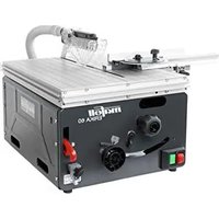
ERIKA 60 - Saw Mafell - Free user manual and instructions
Find the device manual for free ERIKA 60 Mafell in PDF.


| Brand | Mafell |
| Model | ERIKA 60 |
| Product type | Table saw and sliding circular saw |
| Power supply | 230 V~, 50 Hz, 1300 W (nominal load) |
| Nominal current | 5,9 A |
| No-load speed | 5500 min⁻¹ |
| Load speed | 5100 min⁻¹ |
| Max. cutting depth (0°/30°/45°) | 61 mm / 49 mm / 39 mm |
| Tilt range | -2° to 47° |
| Blade diameter max./min. | 190 mm / 180 mm |
| Blade bore | 30 mm |
| Extraction connection diameter | 58 mm |
| Weight | 22,2 kg |
| Table dimensions (L x W) | 544 x 412 mm |
| Table height (without stand / with stand) | 300 mm / 847 mm |
| Standard equipment | 1 carbide blade ∅190 mm 36 teeth, 1 riving knife, 1 guard, 1 universal guide, 1 clamping piece, 1 push stick, 1 extraction hose, 1 connection hose, 1 service tool, manual and safety booklet |
| Safety devices | Upper and lower guard, riving knife, blade compliant with EN 847-1, suitable flanges, deceleration <10 s, piece guidance, electrical safety EN 62841-1 |
| Routine maintenance | Clean sliding parts, lubricate occasionally, check safety devices every 15 days |
| Available accessories | Stand, additional table, retaining rails, sliding carriage, additional blades, dust bag |
| Spare parts | List at www.mafell.com |
Frequently Asked Questions - ERIKA 60 Mafell
User questions about ERIKA 60 Mafell
0 question about this device. Answer the ones you know or ask your own.
Ask a new question about this device
Download the instructions for your Saw in PDF format for free! Find your manual ERIKA 60 - Mafell and take your electronic device back in hand. On this page are published all the documents necessary for the use of your device. ERIKA 60 by Mafell.
USER MANUAL ERIKA 60 Mafell
natural_image
Industrial machine with visible components and no readable text or symbolsMAF02256/a
WARNUNG
Please read all safety instructions and directions. Failure to comply with the safety instructions and directions can cause electric shock, fire and/or serious injuries. Please retain all safety instructions and directions for future reference.
AVERTISSEMENT
natural_image
Microscopic grayscale image of a material or industrial structure with labeled dimensions (22, 51, 52, 50) and scale marker (8), no readable text or symbols beyond measurement annotations.MAF02264/a

GB - EC Declaration of Conformity
We herewith confirm that the machine Erika 60 complies with the EU directives quoted. The standards listed were used for design and construction. Empowered person for the configuration of the technical documents: Mafell AG
EC type-examination certificate No.: Mafell AG
D - 78727 Oberndorf, den 19.07.2022
40050276
| 1 | Signs and symbols | 24 |
| 2 | Product information | 24 |
| 2.1 | Manufacturer's data | 24 |
| 2.2 | Machine identification | 24 |
| 2.3 | Technical data | 25 |
| 2.4 | Emissions | 25 |
| 2.5 | Scope of supply | 25 |
| 2.6 | Safety devices | 26 |
| 2.7 | Use according to intended purpose | 26 |
| 2.8 | Residual risks | 26 |
| 3 | Safety instructions | 26 |
| 3.1 | Protective cover-related safety instructions | 27 |
| 3.2 | Safety instructions for sawing methods | 27 |
| 3.3 | Backlash - reasons and corresponding safety instructions | 28 |
| 3.4 | Safety instructions for the operation of circular saw benches | 28 |
| 3.5 | Instructions on the use of personal protective equipment | 29 |
| 3.6 | Instructions on service and maintenance | 30 |
| 4 | Setting / Adjustment | 30 |
| 4.1 | Installation / Transport | 30 |
| 4.2 | Mains connection | 30 |
| 4.3 | Upper saw guard | 31 |
| 4.4 | Chip extraction | 31 |
| 4.5 | Saw blade selection | 31 |
| 4.6 | Saw blade change | 31 |
| 4.7 | Riving knife/splitter | 32 |
| 4.8 | Application as pull-push saw | 32 |
| 4.9 | Application as circular saw bench | 32 |
| 5 | Operation | 33 |
| 5.1 | Initial operation | 33 |
| 5.2 | Switching on and off | 33 |
| 5.3 | Overload protection | 33 |
| 5.4 | Cutting depth adjustment | 33 |
| 5.5 | Setting for bevel cuts | 33 |
| 5.6 | Universal stop | 33 |
| 5.7 | Application as parallel stop | 34 |
| 5.8 | Application as cross stop and mitre stop | 34 |
| 6 | Service and maintenance | 35 |
| 6.1 | Examination of the safety devices | 35 |
| 6.2 | Machine care | 35 |
| 6.3 | Storage | 35 |
7 Troubleshooting....35
8 Optional accessories 37
9 Exploded drawing and spare parts list 37
1 Signs and symbols

This symbol is found in all places where you will find information for your safety.
Non-compliance with these instructions may result in very serious injuries.
This symbol indicates a potentially hazardous situation.
If this situation is not avoided, the product or objects in its vicinity may get damaged.

This symbol indicates tips for the user and other useful information.
2 Product information
for machines with product no. 972101 or 972120
2.1 Manufacturer's data
MAFELL AG, Beffendorfer Straße 4, D-78727 Oberndorf / Neckar, Phone +49 (0)7423/812-0, Fax +49 (0)7423/812-218, e-mail: mafell@mafell.de
2.2 Machine identification

Protection class II

CE symbol to document compliance with the basic safety and health requirements according to Appendix I of the Machinery Directive.
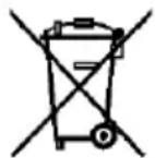
For EU countries only
Do not dispose of electric tools together with household waste material!
In accordance with the European directive 2002/96/EC on waste electrical and electronic equipment and transposition into national law, obsolete electrical tools must be collected separately and recycled in an environmentally-compatible manner.

To reduce the risk of injury, please read the operating instructions.
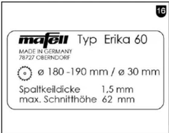
The machine and identification signs on the front and rear side according to figures 15 and 16 (Page 4).
2.3 Technical data
| Universal motor, radio and TV interference suppressed | 230 V~, 50 Hz | |
| Power input (nominal load) | 1300 W | |
| Current at nominal load | 5,9 A | |
| Saw blade speed during idling | 5500 rpm | |
| Saw blade speed at normal load | 5100 rpm | |
| Cutting depth 0°/30°/45° | 2 - 61/49/39 mm (1/8 - 2 13/32 in./1 59/64 in./1 17/32 in.) | |
| Tilting saw unit | -2° - 47° | |
| Saw blade diameter max/min | 190/180 mm (7 1/2 in. / 7 3/32 in.) | |
| Saw blade body thickness | 1,4 mm (1/16 in.) | |
| Tool cutting width | 2,0 mm (5/64 in.) | |
| Saw blade mounting hole | 30 mm (6 3/4 in.) | |
| Diameter extraction connection | 58 mm (2 9/32 in.) | |
| Weight | 22,2 kg (48.9 lbs) | |
| Dimensions: | ||
| Size of the tabletop | 544 x 412 mm (21 3/8 x 16 1/4 in.) | |
| Height of the tabletop | without | 300 mm (11 3/4 in.) |
| underframe | 847 mm (33 1/4 in.) | |
| with underframe |
2.4 Emissions
The declared noise emission values have been measured in accordance with DIN EN 62841-3-1 and may be used for comparing the tool Erika with another and also in a preliminary assessment of exposure.

Danger
The noise emissions during actual use of the power tool Erika can differ from the declared values depending on the ways in which the tool is used especially what kind of workpiece is processed.
Always wear hearing protection, even when the power tool is running idle in addition to the trigger time!
2.4.1 Noise emission specifications
Noise emission values determined according to EN 62841:
| Sound pressure level | L_PA = 89 dB (A) |
| Uncertainty | K_PA = 3 dB (A) |
| Sound power level | L_PA = 104 dB (A) |
| Uncertainty | K_PA = 3 dB (A) |
The noise measurement was recorded using the saw blade included in the standard equipment.
2.5 Scope of supply
Pull-push saw Erika 60 complete with:
1 carbide-tipped circular saw blade ∅ 190 mm (7 1/2 in.), 36 teeth
1 riving knife/splitter (thickness 1.5 mm / 1/16 in.)
1 saw guard with extraction connection
1 universal stop
1 clamping piece
1 pushing stick
1 extraction hose
1 branch pipe (connection of upper and lower extraction connection)
1 service tool in bracket on the machine
1 operating manual
1 folder "Safety instructions"
2.6 Safety devices

Danger
These devices are required for the machine's safe operation and may not be removed or rendered inoperative.
Before operating the machine, check the safety devices for function and possible damage. Do not use the machine with missing or ineffective safety devices.
The machine is equipped with the following safety devices:
- Upper saw guard
- Lower saw guard
- Splitting wedge
- Saw blade (after EN 847-1)
- Appropriate saw blade flanges
- Slowing time less than 10 s
- Stop system for safe guiding of workpiece
- Extraction connection
- Electrical safety corresponds to EN 62841-1
2.7 Use according to intended purpose
The pull-push saw Erika is only suitable as a circular saw bench and cross pull mitre saw for longitudinal and cross cutting of solid wood. Panel materials such as chip board, core board and medium density fibre board can also be processed.
Use approved saw blades according to EN 847-1. Any other use than described above is not permissible. The manufacturer cannot be held liable for any damage arising from such other use.
In order to use the machine as intended, comply with the operating, maintenance, and repair instructions specified by Mafell.
2.8 Residual risks

Danger
Even if used in accordance with its intended purpose and despite conforming with the safety instructions, residual risks caused by the intended use that can lead to health consequences will always remain.
- Touching the moving saw blade within the cutting range.
- Cuts caused by the sharp saw blade teeth while exchanging the saw blade.
- Backlash of the workpiece or of workpiece parts.
- Hurling away of individual teeth of the saw blade.
- Touching live parts when the electrical installation spaces are opened and the machine has not been disconnected from the mains.
- Hearing can be impaired when working for long periods without ear protectors.
- Allergies, mucous membrane irritations by wood dust or lubricants.
3 Safety instructions

Danger
Always observe the following safety instructions and the safety regulations applicable in the respective country of use!
3.1 Protective cover-related safety instructions
- Leave protective covers fitted. Protective covers must be in working order and correctly fitted. Loose, damaged or malfunctioning protective covers must be repaired or replaced.
- Always use the saw blade protective cover and the riving knife/splitter for cross cuts. For cross cuts where the saw blade cuts completely through the thickness of the workpiece, the protective cover and other safety devices reduce the risk of injury.
- After completion of operations (e.g. seaming, grooving or splitting using the reversal process) which require removal of the protective cover and/or riving knife/splitter, immediately reattach the protective system. The protective cover and the riving knife/splitter reduce the risk of injuries.
- Before switching on the power tool, make sure that the saw blade does not touch the protective cover, the riving knife/splitter or the workpiece. Accidental contact of these components with the saw blade can lead to a dangerous situation.
- Adjust the riving knife/splitter according to the description in this operating manual. Wrong distances, position and alignment can be the reason why the riving knife/splitter does not effectively prevent a backlash.
- For the riving knife/splitter to function, it must act on the workpiece. If cuts are too short, the riving knife/splitter cannot prevent a backlash. In the case of cuts in workpieces which are too short to allow the riving knife/splitter to engage, the riving knife/splitter is ineffective. Under these conditions, the riving knife/splitter cannot prevent a backlash.
- Use the saw blade matching the riving knife/splitter. For the riving knife/splitter to work properly, the saw blade diameter must match the corresponding riving knife/splitter, the saw blade base body must be thinner than the riving knife/splitter and the tooth width must exceed the width of the riving knife/splitter.
3.2 Safety instructions for sawing methods
- DANGER: Do not place your fingers or hands near the saw blade or in the saw area. A moment of carelessness or slipping could direct your hand towards the saw blade and cause serious injury.
- Only feed the workpiece to the saw blade against the direction of rotation. Feeding the
workpiece in the same direction as the direction of rotation of the saw blade above the bench may cause the workpiece and your hand to be pulled into the saw blade.
- Never use the mitre stop to feed the workpiece when executing longitudinal cuts, and never additionally use the parallel stop for length adjustment when executing cross cuts with the mitre stop. Simultaneously guiding the workpiece with the parallel stop and the mitre stop increases the probability of the saw blade jamming and a backlash occurring.
- For longitudinal cuts, always exert the feed force on the workpiece between the stop rail and the saw blade. Use a pushing stick if the distance between stop rail and saw blade is less than 150 mm, and a pushing block if the distance is less than 50 mm. This type of working aid ensures that your hand remains at a safe distance from the saw blade.
- Only use the pushing stick supplied by the manufacturer or one that has been manufactured according to the instructions. The pushing stick ensures that there is sufficient distance between hand and saw blade.
- Never use a damaged pushing stick or one that has been sawn into. A damaged pushing stick can break and cause your hand to be caught in the saw blade.
- Do not work "hands only". Always use the parallel stop or the mitre stop to position and guide the workpiece. "Hands only" means that the workpiece is supported or guided with the hands instead of with a parallel stop or mitre stop. "Hands only" sawing leads to misalignment, jamming and backlash.
- Never reach around or over a rotating saw blade. Reaching for a workpiece can lead to unintentional contact with the rotating saw blade.
- Support long and/or wide workpieces behind and/or at the side of the saw bench so that they remain horizontal. Long and/or wide workpieces tend to tip over at the edge of the saw bench; this leads to loss of control, jamming of the saw blade and backlash.
- Feed the workpiece evenly. Do not bend or twist the workpiece. If the saw blade becomes jammed, immediately turn off the power tool,
unplug the power cord and correct the cause of jamming. Jamming of the saw blade by the workpiece may result in backlash or blockage of the motor.
- Do not remove cut material while the saw is running. Sawed material can get stuck between the saw blade and the stop rail or in the protective cover and pull your fingers into the saw blade when you try to remove it. Switch off the saw and wait until the saw blade comes to a standstill before removing the material.
- For longitudinal cuts on workpieces thinner than 2 mm, use an additional parallel stop that is in contact with the bench surface. Thin workpieces can get wedged under the parallel stop and lead to backlash.
3.3 Backlash - reasons and corresponding safety instructions
A backlash is the sudden reaction of the workpiece as a result of a hooked, clamping saw blade or an oblique cut into the workpiece with respect to the saw blade. It can also occur if a part of the workpiece is jammed between the saw blade and the parallel stop or another stationary object.
In most cases, in the event of a backlash, the workpiece is caught by the rear part of the saw blade, lifted off the saw bench and hurled in the direction of the operator.
A backlash is the result of a wrong or incorrect use of the circular saw bench. It can be prevented by taking suitable precautions, as described below.
- Never stand in a direct line with the saw blade. Always hold on to the side of the saw blade on which the stop rail is located. In the event of a backlash, the workpiece can be hurled at high speed onto persons standing in front of and in line with the saw blade.
- Never reach over or behind the saw blade to pull or support the workpiece. Accidental contact with the saw blade may occur, or a backlash may cause your fingers to be pulled into the saw blade.
-
Never hold and press the workpiece that is to be cut off against the rotating saw blade. Pressing the workpiece that is to be cut off against the saw blade leads to jamming and backlash.
-
Align the stop rail parallel to the saw blade. A non-aligned stop rail presses the workpiece against the saw blade and creates a backlash.
- Be particularly careful when sawing in non-visible areas of assembled workpieces. The plunging saw blade can cut into objects that can cause a backlash.
- Support large boards to reduce the risk of backlash caused by a jammed saw blade. Large boards can bend under their own weight. Boards must be supported wherever they project beyond the bench surface.
- Be particularly careful when sawing workpieces that are twisted, knotted, warped, or do not have a straight edge along which they can be guided with a mitre stop or along a stop rail. A twisted, knotted or warped workpiece is unstable and leads to misalignment of the saw kerf with the saw blade, jamming and backlash.
- Never saw several workpieces stacked on top of each other or behind each other. The saw blade could seize one or more parts and cause a backlash.
- If you would like to restart a saw, the blade of which is stuck in the workpiece, centre the saw blade in the saw kerf so that the saw teeth are not stuck in the workpiece. If the saw blade gets stuck, it can lift the workpiece or cause a backlash when the saw is restarted.
- Keep saw blades clean, sharp and adequately set. Never use warped saw blades or saw blades with cracked or broken teeth. Sharp and correctly set saw blades minimise jamming, blocking and backlash.
3.4 Safety instructions for the operation of circular saw benches
- Turn off the circular saw and disconnect it from the power supply before removing the bench insert, changing the saw blade, adjusting the riving knife/splitter or the protective cover of the saw blade, and when leaving the machine unattended. Precautions aim to prevent accidents.
- Never let the circular saw bench run unattended. Switch off the power tool and do not leave it until
it has come to a complete stop. A saw running unattended poses an uncontrolled hazard.
- Children and adolescents must not operate this machine. This rule does not apply to young persons receiving training and being supervised by an expert.
- Make sure that no other persons, in particular children, are present in the work area.
- Set up the circular saw bench in a place that is level and well lit, where you can stand safely and keep your balance. The place of installation must offer enough space to comfortably handle the size of your workpieces. Disorder, unlit working areas and uneven, slippery floors can lead to accidents.
- Consider environmental influences. Do not expose the machine to rain and avoid working in a damp or wet environment as well as near combustible liquids or gases.
- Regularly remove wood shavings and sawdust under the saw bench, from the dust extraction and/or the guides of moving parts. Accumulated sawdust is combustible and can self-ignite.
- Secure the circular saw bench. An improperly secured circular saw bench can move or tip over.
- Remove any adjusting tools, wood remnants, etc. from the circular saw bench before switching it on. Deflection or possible jamming can be dangerous.
- Always use correctly sized saw blades with matching mounting hole (e.g. diamond-shaped or round). Saw blades that do not match the mounting parts of the saw will run out-of-centre and lead to a loss of control.
- Never use damaged or incorrect saw blade mounting materials such as flanges, washers, bolts or nuts. This saw blade mounting material has been specially designed for your saw to ensure safe operation and optimum performance.
- Never stand on the circular saw bench and do not use the circular saw bench as a step stool. Serious injury may occur if the power tool tips over or if you accidentally come into contact with the saw blade.
- Make sure that the saw blade is mounted in the correct direction of rotation. Do not use any grinding wheels or wire brushes with the
circular saw bench. Improper installation of the saw blade or the use of unrecommended accessories may result in serious injury.
- Do not use any saw blades made of high-alloy high-speed steel (HSS saw blades).
- Do not make any changes to the machine that could compromise safety.
- Only use rubber-insulated extension cords (e.g. HO7 RN-F) with a cross section of at least 1.5 mm² when working outdoors and make sure that the cord is not pulled over sharp edges.
- Install and lead the electrical connection cord away from the machine in such a way that there is no danger of stumbling at the operator station.
- Cutting of round timber is not permitted with the standard stops and feed aids.
- Examine the workpiece for foreign objects. Do not saw into metal parts, e.g. nails, since this could damage the sensitive carbide blades.
- Only begin cutting the workpiece when the saw blade has achieved its full speed.
- The wood dust generated during cutting impairs the necessary visibility and is partly harmful to health. The machine must therefore be connected to a sawdust extractor, e.g. a portable small extractor, if the work is not carried out outdoors or in a sufficiently ventilated room. At the same time, the provided extraction hose 5 (Fig. 4 - page 3) must be used as connection of the upper saw guard and the extraction connection 4. The air velocity must be at least 20 m/s (65.6 ft/sec.).
3.5 Instructions on the use of personal protective equipment
- Always wear closely fitting work clothes and take off rings, wristbands, and watches.
- The noise pressure level at the ear generally exceeds 85 dB(A). Operators should therefore wear ear protectors.
- In order to prevent eye injuries always wear an eye protection (safety goggles) or face protection when working with the machine.
3.6 Instructions on service and maintenance
- Before beginning maintenance and repair work, pull the connecting cable out of the socket outlet.
- Only allow an electrician to carry out work on the electrical parts of the machine.
- Damaged cables or plugs must be immediately replaced. Replacement may only be carried out by Mafell or an authorised MAFELL service workshop in order to avoid safety hazards.
- The MAFELL customer service must replace the tabletop, if the table slit has been sawed exceedingly.
- Only original MAFELL spare parts and accessories may be used. Otherwise, the manufacturer will not accept any warranty claims and cannot be held liable.
4 Setting / Adjustment
4.1 Installation / Transport
The machine is delivered in a transportation box. Check the machine for possible transport damages. Damage to the packing material may already be indicative of improper transport. Immediately notify your machine dealer of transport damages.
The following parts are packed loosely and must be installed or attached to the machine before start-up:
- Upper saw guard
- Extraction hose
- Branch pipe (connection of upper and lower extraction connection)
- Universal stop
- Pushing stick
- Clamping piece
Proceed as follows for assembly:
- Upper saw guard
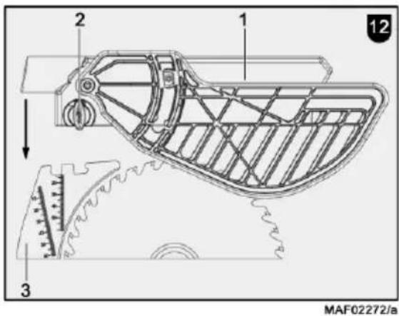
Unscrew the wing bolt 2 (Fig. 12 - page 4) up to the stop. Press this wing screw and push the saw guard 1 horizontally onto the riving knife/splitter 3. Make sure that the guide piece of the wing bolt is firmly engaged in the drill hole of the riving
knife/splitter when you release the wing bolt. Retighten the wing bolt 2.
For short-term storage of the upper saw guard, clamp 36 (Fig. 4 - page 3) and stop 37 into which the saw guard can be hooked are provided on the rear side of the machine.
• Extraction hose and branch pipe
➢ First of all, fit the branch pipe 4 (Fig. 4 - page 3) on the extraction connection at the lower saw guard. Connect the extraction connection on the upper saw guard to the extraction hose 5. Push this hose onto the appropriate connection of the branch pipe.
- Universal stop
The installation of the universal stop is described in chapter 5.6.
- Pushing rod / pushing handle
You can store the provided pushing rod 60 (Fig. 6 - page 3) at the front right of the machine in the retaining bracket intended for this purpose. For storing the pushing handle (special accessory), use the drill holes on the front right or rear left on the longitudinal sides of the machine, in which you can hook the pushing handle. According to your requirements, you can attach a pushing rod to the pushing handle. For this purpose, place the handle onto the pushing rod and press both tips into the timber. Then press on the wing bolt and screw it in.
- Clamping piece, cpl.
For storage purposes, the clamping piece (of the universal stop) can be fastened on the bracket 35 intended for this purpose (Fig. 6 - page 3).
4.2 Mains connection
Prior to commissioning make sure that the mains voltage complies with the operating voltage stated on the machine's rating plate.
4.3 Upper saw guard
The upper saw guard is designed in accordance with legal requirements. The saw guard and side covers are designed to prevent unintentional contact between the user and the saw blade sprocket area. So as to ensure this, the side covers always rest on the table top or the workpiece and automatically adapt to the thickness of the workpiece. However, in the case of unfavourable angles and/or workpiece thicknesses, automatic opening is physically not possible. The workpiece or the stop system then presses the side cover in the direction of the saw blade. Please observe the following instructions to prevent this:
- Always adapt the cutting depth to the workpiece thickness, see section 5.4.
- If necessary, set a sufficient distance between the stop and the saw blade to allow the side covers to slide freely.
- For acute-angled sections, select the working direction so that the side covers meet the workpiece edge as perpendicular as possible.
- Regularly clean the upper saw guard with a clean cloth. Do not use any detergents and lubricants on the upper saw guard.
4.4 Chip extraction
Connect the machine to a suitable external dust extractor during all work generating a considerable amount of dust. The air velocity must be at least 20 m/s (65.6 ft / sec.).
The inner diameter of the extraction connection is 58 mm (2 9/32 in.).
If you use the machine outdoors or in sufficiently ventilated rooms, you can also insert the dust bag that is available as special accessory for short-term operation. Do not forget that this must be exchanged at the latest when it is 75% full (with oak and beech wood dust ensure a dust free disposal!).
4.5 Saw blade selection
Use a sharp tool to obtain a good cut quality and select a tool from the following list according to material and application:
Cutting of solid wood crosswise and lengthwise to the grain direction and cutting of uncoated chip boards, plywood and the like:
- TCT circular saw blade ∅ 190 x 2.0 x 30, (7 1/2 in. ∅ / 30 mm bore / 5/64 in. thickness), 36 alternate top bevels
Cutting of coated boards:
- TCT circular saw blade ∅ 190 x 2.0 x 30, (7 1/2 in. ∅ / 30 mm bore / 5/64 in. thickness), 30 hollow bevels
Cutting of softwood crosswise to the grain direction:
- CV circular saw blade ∅ 190 x 2.0 x 30, (7 1/2 in. ∅ / 30 mm bore / 5/64 in. thickness), 56 teeth
4.6 Saw blade change

Danger
Pull the power plug during all service work.
- Set the saw blade to the maximum cutting depth (see chapter 5.4).
- Turn the wing bolt 2 (Fig. 12 - page 4) on the upper saw guard counterclockwise up to the stop. Push in the wing bolt and pull off the saw guard upwards.
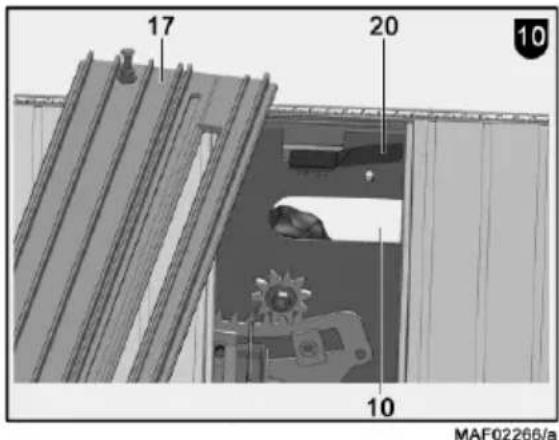
- Reach through the front handle recess 10 (Fig. 10 – page 4) and pull the spring catch 20 forward. Lift the table insert 17, pull it forward and remove it.
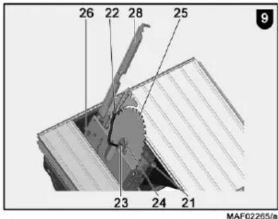
- Open the cover 28 (fig. 9 - page 4) by swinging it upwards or backwards.
- Press the locking button 21 (Fig. 9 - page 4) and turn the saw blade 25 until the button engages. Remove the hexagon head socket wrench 22 from its retaining bracket 26 on the lower saw guard and release the hexagon socket head cap screw 23 by turning clockwise.
- Remove the front saw blade flange 24 and remove the saw blade 25 upwards.
- Insert the new saw blade.
-
Insert the flange 24 onto the two flats and tighten the hexagon socket head cap screw 23 by turning it counterclockwise with the hexagon head socket wrench. Release the locking button.
-
Check whether the saw blade runs smoothly when turning by hand.
- If required, adjust the riving knife/splitter correctly (see chapter 4.6).
- Remove the hexagon head socket wrench 22 and insert into the retaining bracket.
- Close the cover 28 by swinging it forward and locking it in place.
- Push the table insert underneath the rear table edge and then push it downward at the front until it engages against the spring.
- Fit the upper saw guard 1 (Fig. 12 - page 4) with depressed wing bolt horizontally onto the riving knife/splitter and ensure that the guide piece of the wing bolt has firmly engaged in the drill hole on the riving knife/splitter when you release the wing bolt. Retighten the wing bolt 2.
4.7 Riving knife/splitter

Danger
Pull the power plug during all service work.
During longitudinal cutting, the riving knife/splitter prevents that the kerf closes behind the saw blade, resulting in a backlash of the workpiece.
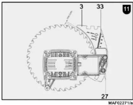
However, this function is only guaranteed if the riving knife/splitter is set correctly, i.e. if its distance to the tooth rim of the saw blade across the entire cutting depth is max. 5 mm (see Fig. 11) and its thickness ranges between the kerf width and the body thickness of the saw blade used. The provided riving knife/splitter matches the carbide tipped saw blades specified in Section 4.4.
Proceed as follows, if it is necessary to adjust the riving knife/splitter:
- Set the saw blade to the maximum cutting depth (see chapter 5.4).
- Remove the upper saw guard (see chapter 4.5).
- Reach through the front handle recess 10 (Fig. 10 – page 4) and pull the spring catch 20 forward. Lift the table insert 17, pull it forward and remove it.
-
Push the riving knife/splitter with its retaining bracket downward into the latching position for concealed cuts.
-
Release the two hexagon socket head cap screws 27 (Fig. 11 - page 4) and adjust the riving knife/splitter 3 according to Fig. 11 with regard to its distance to the tooth rim and its height.
- Tighten the hexagon socket head cap screws 27.
- Reattach the table insert and install the upper saw guard (see chapter 4.5).
The kerf guide can be engaged in two positions without requiring tools:
- upper position with saw guard - for normal cuts
- lower position without saw guard - for covered cuts
In order to attain the respective position just pull the kerf guide upwards and forward or press it down and to the rear.
4.8 Application as pull-push saw
The special advantage when using the saw as pull-push saw is the trouble-free and accurate separating of fixed workpieces up to max. 215 mm (8 7/16 in.) cutting length, e.g. panels. Apply the workpiece against the stop plate rail 6 (Fig. 1 - page 3) of the universal stop 7. Push the handwheel 8 downwards and pull the saw unit with the handwheel forward. After completing the cutting procedure the saw unit runs back to the home position and is stopped there automatically.
4.9 Application as circular saw bench
Slitting of larger workpieces is carried out with the circular saw bench function. For this purpose, position the sawing unit in the foreseen table position. To do so, push the handwheel 8 (Fig. 3 - page 3) downwards and pull the saw unit forward until the circular recess in the pull rod 43 becomes visible. Lock the saw unit in this position by pushing the slide bar 42 upwards on the side.
At the same time, use the universal stop 7 (Fig. 2 – page 3) as parallel stop. In the process, you can insert the stop plate rail 6 depending on the workpiece dimensions either with its high workpiece guiding surface or turned by 90 with its low bearing surface 6 (Fig. 5 – page 3).
You can return to the push-pull saw function by pulling slide bar 42 diagonally downwards.
5 Operation
5.1 Initial operation
Personnel entrusted to work with the machine must be made aware of the operating instructions, calling particular attention to the chapter "Safety instructions".
5.2 Switching on and off
- Switching on: Press the green switch button 46 (Fig. 3 – page 3).
- Switching off: Press the red switch button 45. The saw shaft is automatically braked, reducing the slowing down time to less than 10 s.
5.3 Overload protection
Triggering of the motor protection is always a sign for motor overload, whereby the cause must be determined and eliminated.
The speed is automatically reduced when the motor is overloaded respectively the motor is automatically shut down in the case of power failure. You can turn the motor on again after the power supply has been resumed.
5.4 Cutting depth adjustment
The cutting depth can be steplessly adjusted by turning the handwheel 8 (Fig. 6 - page 3) from 2 to 62 mm (5/64 - 2.44 in.). Turning clockwise increases the cutting depth; turning anticlockwise decreases the cutting depth.
In order to achieve good cutting quality, the adjusted cutting depth of the saw blade should be approx. 5 mm (1/4 in.) more than the processed material thickness.
Depending upon the position of the kerf guide in both latching positions, the measurement scale 33 mounted on the kerf guide and vertical to the table surface (Fig. 11 - page 4) can be used to adjust a specific cutting depth. This however only applies to saw blades with 190 mm (7 31/64 in.).
If an accurate adjustment of the cutting depth is necessary, e.g. when grooving or chiselling always start from below in order to compensate possible play.
5.5 Setting for bevel cuts

Danger
Make sure before inclining with a running saw blade that neither the universal stop nor workpieces are in the swivel range of the saw blade.
For angles up to 45^ you must first of all release the fixing lever 29 (Fig. 6 – page 3) by turning it counter clockwise. Swivel the saw unit by turning the handle 30. The cutting angle is indicated on the indicator of angle scale 31. Tighten the locking lever 29 again.
If the slide bar 32 is pushed upwards, the saw unit can be tilted by an additional 2^ beyond the two end positions 0^ and 45^ . By resetting the slide bar 32, the basic setting is restored.
5.6 Universal stop
The complete universal stop consists of the rod holder 13 (Fig. 2 - page 3) and the guide rod 16 that can be adjusted inside the retaining bracket. You can place it as required in any position on all sides of the table top in the dovetail guides and clamp it as follows:
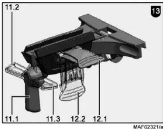
- Turn the clamping lever 11 vertically downwards to the unfastened position 11.1 (Fig. 13 - page 4).
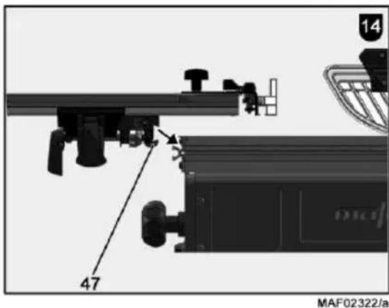
- Then place the rod holder obliquely from above (Fig. 14) against the dovetail profile so that the clamping jaw 47 is pushed to the rear and engages in the profile.
- In the unfastened position 11.1 of the clamping lever, the rod holder can be moved variably on the profile.
- Turn the clamping lever 11 to the left to position 11.2 (Fig. 13) to clamp the rod holder.
By turning the clamping lever to the right to position 11.3 (Fig. 13), the rod holder can be removed from the profile at any position.
Regularly clean the dovetail profile of the machine and of the rod holder as well as the clamping surface of the clamping jaw 47 (Fig. 14) with a suitable cloth. This ensures the required clamping force.
The universal stop can be used both as parallel stop in the circular saw function and also as cross and mitre stop for the pull-push saw.
The position of the stop rail 6 (workpiece positioning) to the mitre stop and/or to the scale has been pre-set at the factory. Nevertheless, if a later adjustment should become necessary, this is accomplished as follows:
- Attach the universal stop in the dovetail guide on the right or left longitudinal side of the table.
- Bring the stop rail to the 0^ position by releasing the upper wing bolt 12 (Fig. 2 - page 3) and tighten the wing bolt.
- Unfasten both cylinder-head screws, which are accessible from above with a screwdriver.
- Unfasten the lateral clamping lever 12.1 (Fig. 13 - page 4) at the rod holder 13 (Fig. 2).
- Then slide the stop rail until just in front of the saw blade.
- Check whether the stop rail is correctly set. Pay attention to the distance between parallel stop and saw blade. The distance at the rear ascending tooth must be slightly larger than at the front descending tooth.
- Clamp the stop rail with the lateral closing lever 12.2 (Fig. 13).
- Retighten the cylinder head screws.
- Carry out a test cut!
If this cut is not ok, start again with the adjustment.
The angle display is retained on the scale after readjusting the stop!
5.7 Application as parallel stop
You can fasten the universal stop in different positions and use it as a parallel stop (see Fig. 2 - page 3). For the adjustment see 5.6. Fastening on the right or left longitudinal side of the table. Pay attention to the distance between parallel guide fence and saw blade. At the rear ascending tooth, the distance must be slightly larger than at the front descending tooth.
- Unfasten the wing screw 12 and set 0° on the angle scale. Retighten the wing bolt 12.
- For this purpose, fasten the guide fence in the dovetail guide in such a way that the fence extension runs from the front edge of the table to
beyond the centre of the saw blade. (Machine in circular saw bench function)
- Set the intended dimension between saw blade and stop rail after unfastening the lateral closing lever 12.1 (Fig. 13 - page 4) on the rod holder 13 (Fig. 2 - page 3) by moving the guide rod 16. The width can be read off the scale 15 at the edge of the stop rail that is facing the saw blade.
- Clamp the lateral closing lever 12.2 (Fig. 13 - page 4) and the clamping lever 11.2 again.
- Fasten the stop rail additionally at the front edge of the table by means of the clamping piece 9 (Fig 3 - page 3).
- To do so, insert the square nut on the clamping piece into the groove of the stop rail.
- Unscrew the wing nut on the clamping piece until the wedge engages behind the dovetail profile of the table top.
- Tighten the wing nut.
The stop of stop rail 6 can be adjusted in longitudinal direction. If there is a risk, e.g. when cutting solid wood longitudinally, of the workpiece jamming between stop and saw blade, then the stop rail is moved in such a way that its rear end reaches approximately up to the centre of the saw blade. To do so, release the clamping arm 14 (Fig. 2 - page 3) arranged on the top of the stop and move the stop rail. After adjusting, tighten the clamping lever again.
The stop rail 6 can be inserted turned by 90°, see Fig. 5 - page 3. This facilitates cutting of narrow workpieces in particular with an inclined saw blade, since the then available low bearing surface enables closer positioning of the parallel stop to the saw blade. For this purpose, release the clamping lever 14 at the stop. Pull the stop rail 6 completely out of the bracket. Insert the stop rail turned by 90° in such a way that the narrow edge points to the saw blade. Then tighten the clamping lever again. When the stop rail is in this position, the cut width can also be read off the scale 15 at the edge facing the saw blade.
5.8 Application as cross stop and mitre stop

Danger
Only carry out adjustments on the universal stop when the saw blade is stationary.
The universal stop is best attached to the front left table side for cross and mitre cuts in pull-push saw function, see Fig. 7 - page 3. For right angled cuts, the 0^ mark is indicated on the angle scale 18 in this position.
For carrying out angular cuts, unfasten the wing bolt 19 (Fig. 7 - page 3) located on the upper side. Tilt the stop rail 6 according to scale 18 into the required position. A latching position is available. Afterwards, tighten the wing bolt.
The latching mechanism can be switched off with the slide bar 44 below the angle scale. Slightly unfasten the wing screw. Then push down onto the part of the slide bar that projects on one side.
The stop rail should always reach as close as possible to the cutting plane in order to achieve better cutting quality. It is therefore notched at its ends, so that the upper saw guard can be moved close enough when cutting thin workpieces. To adjust the stop rail, release the clamping lever 14.
Shifting the guide rod 16 in the rod fixture 13 enables adjusting the stop in such a way that, depending on the respective workpiece dimensions, an optimal adjustment of the cut width can be obtained.
6 Service and maintenance

Danger
Pull the power plug during all service work.
MAFELL machines are designed to be low in maintenance.
The ball bearings used are greased for life. When the machine has been in operation for a longer period of time, we recommend to hand the machine in at an authorised MAFELL customer service shop for inspection.
Only use our special grease, order No. 049040 (1 kg tin) for all greasing points.
6.1 Examination of the safety devices
The safety of the machine depends primarily on the proper functioning of the provided safety devices. It is therefore important that these devices are examined regularly for correct condition. This comprises in particular the riving knife/splitter, the upper saw guard and the lower saw guard.
Furthermore, the following must be checked every two weeks:
- automatic return of the saw unit to the home position when used as a pull-push saw (see chapter 4.7)
- automatic locking of the saw unit in the home position after returning
- trouble-free movement of the saw guard wings from the max. cutting height to the table top.
- mains cable for damage
6.2 Machine care
The sliding and rolling parts must be occasionally cleaned of chips and dust with a suitable vacuum cleaner. Occasional spraying with a commercially available lubricant (e.g. Caramba) facilitates sliding of the parts.
In order to avoid too large a temperature rise of the motor check occasionally that there is no dust deposit on its surface.
6.3 Storage
Clean the machine thoroughly if the machine is not used for a longer period of time. Spray blank metal parts with a rust-proofing agent.
7 Troubleshooting

Danger
Determining the causes for existing defects and eliminating these always requires increased attention and caution. Pull the mains plug beforehand!
Some of the most frequent defects and their causes are listed in the following chart. If case of other defects, please contact your dealer or the MAFELL customer service.
| Defect | Cause | Elimination |
| Machine cannot be switched on | No mains voltage | Check power supply |
| Mains fuse defective | Replace fuse | |
| Carbon brushes worn | Take the machine to a MAFELL customer service shop | |
| Machine switches off automatically during idling | Mains failure | Check mains back-up fusesThe machine does not restart automatically due to the installed under-voltage protection and must be turned on again after power has returned |
| Machine stops while cutting is in process | Mains failure | Check mains back-up fuses |
| Machine overloaded | Reduce feed speed | |
| Workpiece jams when feeding | Blunt saw bladeStop rail of the universal stop is not parallel to the saw blade | Hold workpiece and turn motor off immediately. Then exchange the saw bladeReadjust the stop rail, see chapter 5.6 |
| Burn marks on the cut surfaces | The saw blade used is unsuitable for the task or blunt | Replace saw blade |
| Chip outlet blocked | Operation without extraction | Remove chips while the machine is switched off (see Fig. 8 - page 3).The protective sliding cover 52 must be opened. To do so, detach screw 51 with the Allen key 22.Pull the locking recess 50 on the saw guard downwards and pull the protective sliding cover forward. The chips in the chip duct can now be easily removed downwards.Afterwards close and engage the protective sliding cover again.Caution! Retighten screw 51. |
| Extraction too weakWood particles in the chip ejector | Use an extraction unit, which guarantees an air speed of at least 20 m/s (65.6 ft/sec.) at the extraction connection pieceRemove chips while the machine is switched off (see Fig. 8 - page 3).The protective sliding cover 52 must be opened. To do so, detach screw 51 with the Allen key 22.Pull the locking recess 50 on the saw guard downwards and pull the protective sliding cover forward. The chips in the chip duct can now be easily removed downwards.Afterwards close and engage the protective sliding cover again.Caution! Retighten screw 51. | |
| Height adjustment is sluggish | Threaded spindle, drive segment, and guide rod dirty | Clean components and grease or lubricate |
| Pulling device is sluggish | Pull rod, ball bearing running surface and guide tube dirty | Clean components |
8 Optional accessories
- Stationary equipment (underframe) Order No. 203153
- Supplementary table Order No. 208437
- Support rail 650 mm Order No. 201309
- Support rail 840 mm Order No. 201310
- Universal stop, cpl. Order No. 207914
- Rod holder Erika 60 Order No. 207548
- Stop ruler, cpl. Order No. 201331
- Moving carrier plate Order No. 201320
- Saw blade-TCT ∅ 190 x 2.0 x 30 mm, 36 teeth / alternate top bevel teeth Order No. 092550 (7 1/2 in. ∅ / 30 mm bore / 5/64 in. thickness)
- Saw blade-TCT ∅ 180 x 2.0 x 30 mm, 30 teeth / alternate top bevel teeth Order No. 092511 (7 3/32 in. ∅ / 30 mm bore / 5/64 in. thickness)
- Saw blade-TCT for laminate ∅ 180 x 2.0 x 30 (7 3/32 in. ∅ / 30 mm bore Order No. 092527 / 5/64 in. thickness) 56 teeth / special
- Dust bag Order No. 039829
9 Exploded drawing and spare parts list
The corresponding information in respect of spare parts can be found on our homepage: www.mafell.com
Sommaire
natural_image
Two black-and-white images showing mechanical components, one with a pointed tool and the other with a curved blade (no text or symbols visible)KSS 300 / KSS 40 18M bl KSP 40 Flexistem MT 55 cc
natural_image
Close-up of a mechanical device with no visible text or symbols
natural_image
Exterior view of a modern office building (no signage)MKS 130 Ec - MKS 185 Ec
natural_image
Close-up of a chain-linking saw with visible blades and handle (no text or symbols)ZSX Ec
natural_image
Mechanical device with two circular components mounted on a frame (no visible text or symbols)Z 5 Ec
natural_image
Industrial machine with articulated arm and control panel (no visible text or symbols)
natural_image
Exterior view of a small industrial vacuum cleaner with attached hose (no visible text or symbols)S 35 MERIKA 60 E - B
natural_image
Mechanical device with cylindrical components and metal brackets (no visible text or symbols)
natural_image
Close-up of a mechanical power tool with a circular base and lever mechanism (no visible text or symbols)
natural_image
Industrial cutting tool with mechanical components (no visible text or symbols)DD40 P / DD40 G EVA 150 E ZH 205 Ec - ZH 320 Ec MF 26 cc
natural_image
Mechanical device with mounted components and mounting base (no visible text or symbols)
natural_image
Mechanical device with articulated arms and mounting bracket (no visible text or symbols)SKS 130
natural_image
Mechanical device with circular components and a flat base (no visible text or symbols)
natural_image
Close-up of a mechanical tool or device with no visible text or symbolsLS 103 EcZK 115 EcLO
| GARANTIEGegen Vorlage der Garantieunterlage (Original-Kaufbeleg) werden innerhalb der jeweils gültigen Gewährleistungsregelungen kostenlos alle Reparaturen ausgeführt, die nach unseren Feststellungen wegen Material-, Bearbeitungs- und Montagefehlern erforderlich sind. Verbrauchs- und Verschleißteile sind hiervon ausgeschlossen. Hierzu muss die Maschine bzw. das Gerät frachtfrei an das Werk oder an eine MAFELL-Kundendienststelle geschickt werden. Vermeiden Sie, die Reparatur selbst zu versuchen, da dadurch der Garantieanspruch erlischt. Für Schäden, die durch unsachgemäße Behandlung oder durch normalen Verschleiß entstanden sind, wird keine Haftung übernommen. |
| WARRANTYUpon presentation of the warranty document (original invoice), we will carry out all repairs free of charge in accordance with the applicable warranty provisions, processing and mounting faults free of charge on presentation of this properly filled-in Guarantee Certificate and your original receipt. This is not valid for consumables and wearing parts. For this purpose, the machine or the appliance is to be forwarded freight paid to our plant or to an authorized MAFELL repair service. Refrain from trying to carry out the repairs yourself as otherwise your warranty claim will become extinct. We do not accept any liability for any damage resulting from improper handling or normal wear. |
| GARANTIESur présentation de cette carte de garantie, duement remplie par votre fournisseur et accompagnée de l'original de la pièce justifiant l'achat, nous effectuerons gratuitement toutes les réparations faisant l'objet d'un recours en garantie pendant la période indiquée, de la construction ou de la fabrication, à l'exclusion des pièces de consommation et d'usure. La machine ou l'appareil doit être pour cela expédié franco de port à notre usine ou à un atelier de service après-vente MAFELL. Évitez de procéder vous-mêmes à toute réparation, ceci périmant tout recours en garantie par la suite. Nous déclinons toute responsabilité en cas de dommages découlant d'une manipulation non conforme ou d'une usure normale. |
| GARANZIADietro presentazione del presente certificato di garanzia, regolarmente compilato, insieme alla ricevuta originale, vengono eseguite gratuitamente tutte le riparazioni necessarie riscontrate dai nostri accertamenti, entro il periodo di garanzia vigente, dovuti a difetti di materiale, di lavorazione o di montaggio. Da ciò sono esclusi pezzi di consumo e pezzi soggetti ad usura. A questo scopo la macchina ovvero l'apparecchio (eletrico) va spedito franco di porto allo stabilimento oppur e a d un punto di assistenza clienti della MAFELL. Evitate di tentare Voi stessi di effettuare la riparazione, altrimenti il diritto di garanzia viene revocato. Non ci assumiamo alcuna responsabilità per danni derivanti da trattamento non conforme o da normale usura. |
| GARANTIETegen vertoon van dit reglementair ingevuld garantie-bewijs, samen met het originele koopbewijs worden binnen de telkens geldige garantieregelingen gratis alle reparaties uitgevoerd, die volgens onzeconstateringen op grond van materiaal-, bewerkings- en montagefouten vereist zijn. Verbruik- en slijtagedelen zijn hiervan uitgesloten. Hiervoor moet de machine resp. het apparaat vrachtvrij naar de fabriek of naar een MAFELL-klantenservice worden gestuurd. Vermijdt u het de reparatie zelf uit te voeren, omdat daardoor de garantieclaim vervalt. Voor schade die door ondeskundige behandeling of door normale slijtage is ontstaan, wordt geen aansprakelijkheid aanvaardt. |
| GARANTÍAPresentando este documento de garantía (recibo original de compra), todas las reparaciones necesarias por defectos de material, errores de mecanizado o faltas de montaje en el marco de las reglamentaciones de la garantía concedida por parte del fabricante se efectuarán libre de gastos. Se excluyen sin embargo piezas fungibles o de desgaste. Para ello, entregue a porte pagado la máquina o el equipo a las fábricas del fabricante o a uno de los puntos de asistencia técnica de MAFELL. No realice nunca las tareas de reparación a cuenta propia. De lo contrario, caducará el derecho a garantía. No se asumirá responsabilidad alguna por los daños que se desprendan del uso inapropiado ni por el desgaste en el uso diario. |
| TAKUUTätä takuukuittia (alkuperäinen ostokuitti) vastaan suoritetaan voimassa olevan takuuajan sisällä maksutta kaikki korjaukset, jotka olemme todenneet tarpeellisiksi materiaali-, valmistus- ja asennusvirheistä johtuen. Käyttö- ja kuluvat osat ei kuulu takuupiiriin. Korjausta varten kone tai laite on lähetettävä asianmukaisesti postitettuna joko tehtaalle tai johonkin MAFELL-asiakaspalveluun. Älä yritä korjata konetta itse, koska siinä tapauksessa takuu sammu. Takuu ei vastaa vahingoista, jotka johtuvat asiaankuulumattomasta käytöstä tai normaali sta kulumisesta. |
| GARANTIMot uppvisande av kvitto utförs kostnadsfritt, under giltiga garantiåtaganden, alla reparationer som efter fastställande från vår sida kan härledas till material-, bearbetnings- eller monteringsfel. Förbruknings- och förslitningsdelar undantagna. Maskinen eller verktyget måste skickas fraktfritt till fabrik eller till MAFELLkundservice. Undvik att själv försöka utföra reparationen då detta leder till att garantianspråk förfaller. För skador som uppkommer på grund av felaktig behandling eller normalt slitage övertas inget ansvar. |
| GARANTIMod fremlæggelse af garantibeviset (original kvittering) ydes der gratis reparation af materiale-, fremstillings- og monteringsfejl, i henhold til de gældende garantibetingelser. Forbrugs- og sliddele udelukkes fra denne garanti. Hertil sendes maskinen/apparatet fragtfrit til producenten eller et Mafell-kundeserviceværksted. Hvis kunden selv forsøger at reparere maskinen, bortfalder garantien. Der overtages intet ansvar for beskadigelser, der opstår pga. uhensigtsmæssig brug eller normal slitage. |
| ГарантияПри предъявлении документации на гарантию (оригинальная квитанция) в соответствии с правилами о предоставлении гарантии мы бесплатно произведем все необходимые ремонты, которые по нашему определению необходимы в связи с дефектом материала, обработки и сборки. Это не относится к расходным материалам и изнашиваемым деталям. Для этого машина или устройство должно быть франко-фрахт отправлено на завод или мастерскую обслуживания клиентов фирмы MAFELL. Избегайте попыток самостоятельного ремонта, поскольку в этом случае гарантия аннулируется. Мы не несем ответственности на вред, причиненный в результате неправильного обращения или естественного износа. |
| GWARANCJAPo przedstawieniu gwarancji (oryginału dowodu zakupu) wykonane zostaną w ramach terminu gwarancji wszelki ego rodzaju naprawy, które według naszej oceny są konieczne z powodu błędów materialowych oraz błędów przy obróbce i montażu.Nie dotyczy to części zamienne i zużywalne. Prosimy o przesłanie maszyny wzgl. urządzenia na nasz koszt do zakładu lub serwisu MAFELL. Unikać dokonywania samodzielnych napraw, gdyż powoduje to utratę roszczeń gwarancyjnych. Nie przejmujemy odpowiedzialności za szkody powstałe w wyniku niefachowej obsługi lub normalnego zużycia. |
| ZÁRUKAPo předložení záručních podkladů (originální doklad o koupi) budou provedeny v rámci aktuálně platných pravidel pro poskytování záruky provedeny všechny opravy, které jsou podle našich zjištění požadovány z hlediska vad materiálu, zpracování a montáže. Díly podléhající používání a opotřebení jsou z tohoto vyjmuty. Navíc k tomu musí být stroj, případně přístroj zaslán vyplaceně do závodu nebo zákaznického servisu MAFELL. Nezkoušejte stroj opravovat sami, protože tím zaniká nárok na záruku. Záruky se nevztahují na škody vzniklé neodbornou manipulací nebo na ty, které vznikly v důsledku normálního opotřebování. |
| GARANCIJAOb priložitvi garancijske dokumentacije (originalni nakupni račun) bodo v okviru veljavnih garancijskih pogojev brezplačno opravljena vsa popravila, ki so po naši oceni potrebna zaradi napak v materialu, obdelavi in montaži. Porabni in obrabni deli so izvzeti iz tega določila. V ta namen morate stroj oz. napravo prosto voznine poslati v tovarno ali v pooblaščeno MAFELL servisno delavnico. Popravil ne skušajte opravljati samostojno, saj s tem ugasne pravica do garancije. Za škodo, ki nastane zaradi nestrokovnega ravnanja ali zaradi normalne obrabe, ne prevzemamo odgovornosti. |
| ZÁRUKAPo predložení záručného listu (originálneho dokladu o kúpe) budú všetky opravy, ktoré určíme ako nevyhnutné z dôvodu chýb materiálu, spracovania a montáže, vykonané bezplatne v rámci platných záručných predpisov. Spotrebné diely a diely podliehajúce opotrebeniu sú z toho vylúčené. K tomu sa musí zaslať stroj alebo prístroj bez dopravného do podniku alebo zákaznickeho servisu MAFELL. Vyhnite sa pokusom o samostatnú opravu, pretože tým stratíte nárok na záruku. Za škody spôsobené neodbornou manipuláciou alebo bežným opotrebovaním nepreberáme žiadnu zodpovednosť. |

MAFELL AG
Beffendorfer Straße 4, D-78727 Oberndorf / Neckar
Telefon +49 (0)7423/812-0
Internet:
E-Mail:
Fax +49 (0)7423/812-218
www.mafell.de
mafell@mafell.de
- WARNUNG
- AVERTISSEMENT
- GB - EC Declaration of Conformity
- Signs and symbols
- Product information
- Manufacturer's data
- Machine identification
- Technical data
- Emissions
- Danger
- Noise emission specifications
- Scope of supply
- Safety devices
- Use according to intended purpose
- Residual risks
- Safety instructions
- Protective cover-related safety instructions
- Safety instructions for sawing methods
- Backlash - reasons and corresponding safety instructions
- Safety instructions for the operation of circular saw benches
- Instructions on the use of personal protective equipment
- Instructions on service and maintenance
- Setting / Adjustment
- Installation / Transport
- - Upper saw guard
- • Extraction hose and branch pipe
- - Universal stop
- - Pushing rod / pushing handle
- - Clamping piece, cpl.
- Mains connection
- Upper saw guard
- Chip extraction
- Saw blade selection
- Cutting of solid wood crosswise and lengthwise to the grain direction and cutting of uncoated chip boards, plywood and the like:
- Cutting of coated boards:
- Cutting of softwood crosswise to the grain direction:
- Saw blade change
- Riving knife/splitter
- Application as pull-push saw
- Application as circular saw bench
- Operation
- Initial operation
- Switching on and off
- Overload protection
- Cutting depth adjustment
- Setting for bevel cuts
- Universal stop
- Application as parallel stop
- Application as cross stop and mitre stop
- Service and maintenance
- Examination of the safety devices
- Machine care
- Storage
- Troubleshooting
- Optional accessories
- Exploded drawing and spare parts list
- Sommaire
Brand : Mafell
Model : ERIKA 60
Category : Saw