
PFU 2000 - Electrical relay Grundfos - Free user manual and instructions
Find the device manual for free PFU 2000 Grundfos in PDF.

| Product type | Relay module for twin circulator |
| Brand | Grundfos |
| Model | PFU 2000 |
| Main functions | Alternating, standby, separate operation; signal output for run/fault indication; green and red LEDs |
| Power supply | Via circulator (230 V AC single-phase or three-phase depending on model) |
| Signal output | Potential-free changeover contact, 250 V, 2 A AC max, 5 V, 1 mA DC min |
| On/off input | Potential-free external contact, 250 V, 1.5 mA max, 100 V, 0.5 mA min |
| Operating modes | Alternating (swap every 24 h), standby (one head active), separate (independent) |
| Thermal protection | Ipsotherm integrated in the circulator |
| Light indicators | Green LED (run) and red LED (fault/stop) |
| Package contents | 2 relay modules, 2 threaded cable glands, 1 4-wire connecting cable, 2 wiring diagrams |
| Connecting cable | 4-wire, supplied, for alternating and standby operation |
| Safety | Disconnect power before any intervention; do not use with frequency converter |
| Maintenance | No specific maintenance required; periodically check proper operation |
| Spare parts and repairability | Relay modules individually replaceable; use the supplied diagrams |
| General information | Designed for Grundfos twin circulators; installation in accordance with applicable regulations |
Frequently Asked Questions - PFU 2000 Grundfos
User questions about PFU 2000 Grundfos
0 question about this device. Answer the ones you know or ask your own.
Ask a new question about this device
Download the instructions for your Electrical relay in PDF format for free! Find your manual PFU 2000 - Grundfos and take your electronic device back in hand. On this page are published all the documents necessary for the use of your device. PFU 2000 by Grundfos.
USER MANUAL PFU 2000 Grundfos
Installation and operating instructions
Page 4

Before removing the terminal box modules, these Fitting Instructions should be studied carefully. The installation and operation should also be in accordance with local regulations and accepted codes of good practice.
Note: Pumps with modules must not be connected to a frequency converter.
The set includes:
- 2 relay modules with screws and screwdriver.
- 2 screwed cable entries.
1 intermediate cable. - 2 wiring diagrams for the terminal box covers.
When fitted with relay modules, the twin-head pump can be connected directly to a mains switch as it will be protected by the built-in overload protection at all three speeds.
The relay modules incorporate two indicator lights, see fig. 1, and a signal output in the terminal block.
2. Signal output
By means of a selector switch, see fig. 1, the signal output can be set to activation during:

Operation: The output is activated when the pump is operating.

Fault: The output is activated in case of fault.

Alternating operation: Use this setting when the pumps are to operate alternately as duty and standby pump.
The function of the signal output is shown in the table in section 6. Indicator lights and signal output.
3. Indicator lights
The relay modules have a green and a red indicator light. The function of the indicator lights is shown in the table in section 6. Indicator lights and signal output.
4. Operating modes of twin-head pumps
Three operating modes are possible:
- Alternating operation. The pumps operate alternately as duty and standby pump.
- Standby operation. One pump operates constantly as duty pump and the other constantly as standby pump.
- Single-pump operation. The pumps operate independently of each other, possibly with external operating or fault indication.
5. Intermediate cable
In alternating operation and standby operation, the terminal blocks of the relay modules must be connected via the 4-core cable supplied. The cable is led into each of the terminal boxes by means of the screwed cable entries, see fig. 2.
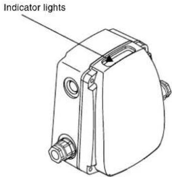
Fig. 1
TM0092334596TM0092364596
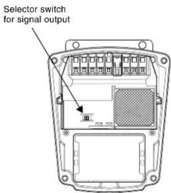
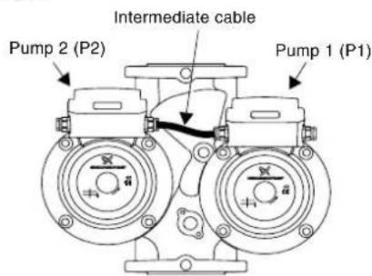
Fig. 2
TM0092434101
6. Indicator lights and signal output 7. Replacement
| Indicator lights | Signal output activated during | Description | ||
| Green Red | Operation | Fault | ||
| Off Off | NCKOC3 | NCKOC3 | The pump has been stopped. The elec-tricity supply has been switched off or phase missing. | |
| On Off | NCKOC3 | NCKOC3 | The pump is operat-ing. | |
| On On | NCKOC3 | NCKOC3 | Three-phase pumps only:The pump is operat-ing, but the direction of rotation is wrong. | |
| Off On | 123NCKOC | 123NCKOC | The pump has been cut out by the thermal overload switch. | |
| Flashes Off | NCKOC3 | NCKOC3 | The pump has been stopped by an external on/off switch. | |
| Flashes On | NCKOC3 | NCKOC3 | The pump is or has been cut out by the thermal overload switch and the externall on/off switch is switched off. | |

Before removing the terminal box covers, make sure that the electricity supply has been switched off and that it cannot be accidentally switched on.
- Switch off the electricity supply to the pump by means of the external mains switch. The green indicator lights on the terminal boxes must be off.
- Remove the terminal box covers.
- Remove all wires from the terminal blocks.
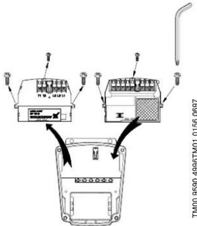
- Replace the existing modules in the terminal boxes by the new ones, see fig. 3. For removal/fitting of the three screws shown, use the screwdriver supplied with the modules.
GB
Fig. 3
TM00 9590 4996TM01 0156 0697
- Replace the wiring diagrams in the terminal box covers by the diagrams supplied with the modules, see fig. 4.
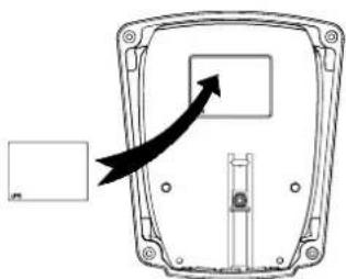
Fig. 4

- Connect the terminal blocks and set the selector switch according to the following table which refers to the diagrams at the end of these instructions.
| Single-pump operation (the pumps are operating independently of each other) | |
| With operating indication Fig. A | |
| With fault indication Fig. B | |
| Alternating operation or standby operation (use the intermediate cable supplied, see fig. 2) | |
| Alternating Operation Fig. C | |
| Standby operation with pump 1 as duty pump and pump 2 as standby pump. Note: The selector switch must not be set to alternating operation. | Fig. D |
| Standby operation with pump 2 as duty pump and pump 1 as standby pump. Note: The selector switch must not be set to alternating operation. | Fig. E |
| Fault or operating indication for twin-head pumps in alternating operation: If the signal output is to be used for fault or operating indication, an intermediate relay must be used. Figure F shows a single-phase pump in alternating operation with external fault indication if pump 2 or both pumps are faulty. | Fig. F |
| Fault or operating indication for twin-head pumps in standby operation: · If the signal output of the duty pump is to be used for fault or operating indication, an intermediate relay must be used. · If the signal output of the standby pump is to be used for fault or operating indication, proceed as shown in fig. A or B. | |
- Electrical data
| Input for start/stop (terminals 7 and 8) | External potential-free contact. Maximum load: 250 V, 1.5 mA. Minimum load: \( {100}\mathrm{\;V},{0.5}\mathrm{\;{mA}} \) . |
| Output for operating or fault indication (terminals 1 to 3) | Internal potential-free changeover contact. Maximum load: 250 V, 2 A, AC. Minimum load: \( 5\mathrm{\;V},1\mathrm{\;{mA}},\mathrm{{DC}} \) . |
- In the case of alternating operation: Make a functional test as described in section 9. Functional test in the case of alternating operation.
- Fit the terminal box covers.
- Switch on the electricity supply.
9. Functional test in the case of alternating operation
Note: Before beginning the functional test, the pump must be installed and be ready for operation.
To check whether the intermediate cable is connected correctly, proceed as described in the following table. The test is carried out in two steps, each ending with a check.
| Step 1 | ||
| 1 | Both pumps: Check that the electricity supply has been switched off. | |
| 2 | Pump 1: Set the selector switch for the signal output to alternating operation. Pump 2: Set the selector switch for the signal output to fault indication. | |
| 3 Both pumps: Remove the speed switch. | ||
| 4 Both pumps: Switch on the electricity supply. | ||
| Check | Pump 1: • The pump is not operating. • The green indicator light is off. • The red indicator light is on. | Pump 2: • The pump is not operating. • The green indicator light is off. • The red indicator light is on. |
| Step 2 (if the above check is OK) | ||
| 1 Both pumps: Switch off the electricity supply. | ||
| 2 Both pumps: Fit the speed switch. | ||
| 3 Both pumps: Switch on the electricity supply. | ||
| Check | The twin-head pump is running alternating operation with pump changeover every 24 hours. The pumps do not start in a specific order when the electricity supply is switched on. Pump 1 (pump 2): • The pump is operating. • The green indicator light is on. • The red indicator light is off. | Pump 2 (pump 1): • The pump is not operating. • The green indicator light is flashing. • The red indicator light is off. |
10. Disposal
Disposal of this product or parts of it must be carried out according to the following guidelines:
- Use the local public or private waste collection service.
- In case such waste collection service does not exist or cannot handle the materials used in the product, please deliver the product or any hazardous materials from it to your nearest GRUND-FOS company or service workshop.
Subject to alterations..
Ynoketai eTporonouoeic.
22 Floor, Xin Hua Lian Building
755-775 Huai Hai Rd. (M)
Shanghai 200020
PRC
Phone:+86-512-67611180
Telefax:+86-512-67618167
Czech Republic
GRUNDEOS s.r.o.
Caikovského 21
779.00 Olomouc
Phone: +420-68-5716 111
Telefax:+420-68-543 8908
Finland
OY GRUNDFOS Pumput AB
Mestarintie 11
Piispankylä
FIN-01730 Vantaa (Helsinki)
Phone: +358-9 878
Telefax: +358-9 878 91550
France
Pompes GRUNDEOS Distribution
S.A.
Unit 1. Ground floor
Siu Wai Industrial Centre
29-33 Wing Hong Street &
68 King Lam Street, Cheung Sha
Wan
Kowloon
Phone:+852-27861706/27861741
Telefax:+852-27858664
Hungary
GRUNDFOS Hungaria Kft.
Park u.8
H-2045 Torokbalint.
Phone: +36-34 520 100
Telefax:+36-34520200
India
GRIUNDEOSBumpsonIndiaPrivate
Limited
Flat A. Ground Floor
61/62 Chamiers Aptmt
Chamiers Road
Chennai 6
Phone:+91-444323487
Telefax: +91 44 432 3489
Indonesia
PT GRUNDFOS Pompa
JI. Rawa Sumur III, Blok III / CC-1
Kawasan Industri, Pulogadung
Jakarta 13930
Phone:+62-214606909
Telefax:+62-21-460 6910/460
6901
.
Ireland CUNDP205 (Irrolant) 1+4
Unit 34 Stillorgan Industrial Park
Blackrock
County D
Phone:+153-1-2954976
Tel:400-253-1395
- CiteX: +353-2-2944739
Italy
GRUNDEOS Pompe Italia S.r.l.
Via Gran Sasso 4
1-2-3, Shin Miyakoda
Hamamatsu City
Shizuoka pref. 431-21
Phone: +81-53-428 4760
Telefax:+81-53-4841014
Korea
GRUNDFOSPumps Korea Ltd.
2nd FL, Dong Shin Building
994-3 Daechi-dong, Kangnam-Ku
Seoul 135-280
Phone:+82-2-5317600
Telefax:+82-2-5633725
Molvin
MUNIDSYU GRIUNDEOS PUMPO Sdn. Pte. Ltd.
2.1.1.1.1.3.1.2.1.3.4.1.5.1.6.1.7.1.8.1.9.10.11.12.13.14.15.16.17.18.19.20.21.22.23.24.25.26.27.28.29.30.31.32.33.34.35.36.37.38.39.40.41.42.43.44.45.46.47.48.49.50.51.52.53.54.55.56.57.58.59.60.61.62.63.64.65.66.67.68.69.70.71.72.73.74.75.76.77.78.79.80.81.82.83.84.85.86.87.88.89.90.91.92.93.94.95.96.97.98.99.100
Glenomaia Industrial
Grennane Industrial Park 40156-6cbh Alam
40157ShamSham
Selangor
Flone: +60 3-53692922
Telefax:+60-3-53692866
Mexico
Bombas GRUNDFOS de Mexico
S.A.de C.V
Boulevard TLC No. 15
Parque Industrial Stiva Aerop
uerto
Apodaca, N.L. 66600
Mexico
Phone:+52-81-8144 4000
Telefax:+52-81-81444010
Netherlands
North Harbour Industrial Estate
Albany Auckland
Phone:+64-9-4153240
Telefax:+64-9-4153250
m = 311
Norway
GRUNDFOS Pumper A/S
Strømsveien 344
Postboks 235, Leirdal
N-1011Oslo
TIf.: +47-22 90 47 00
Telefax:+47-22322150
Poland
GRUNDEOSPompysSp.zgq.
ul.Klonowa 23
PI-62-081 Przczmicrowo
Phone:+48616501300
Telefax: +48-61-650 13 50
Portugal
Bomhas GRUNDEOS Portugal, S.A.
Tunglo Industrial Park
Tunglo, Miao-Li Count:
Taiwan, R.O.C.
Phone:+886-37-980557
Telefax: +886-37-98 05 70
Thailand
GRUNDFOS (Thailand) Ltd.
947/168 Moo 12, Bangna-Trad Rd.
K.M.3,
Bangna, Phrakanong
Bangkok 10260
Phone:+66-2-7441785...91
Telefax:+66-2-7441775...6
Turkey
GRUNDFOS POMPASAN.ve TIC
LTD.STI
Bulgurlu Caddesi no. 32
TR-81190Usk
Phone:+90-216-4280306
Telefax:+90-216-3279988
United Arab Emirates 104
GRUNDFOS Gulf Distribution
P.O.Box 16768
Jebel All Free Zone
Dunal
Phone: +971-4-8815 166
Telefax:+971-4-8815136
United Kingdom
GRUNDFOSPumps Ltd.
Grovebury Road
Leighton Buzzard/Beds, LU7 8TL
Phone:+44-1525-850000
Telefax: +44-1525-85001
U.S.A.
GRUNDFOSPumpsCorporation
17100 West 118th Terrace
Olathe, Kansas 66061
Phone:+1-913-227-3400
Telefax: +1-913-227-3500


- Signal output
- Indicator lights
- Operating modes of twin-head pumps
- Intermediate cable
- Indicator lights and signal output 7. Replacement
- Functional test in the case of alternating operation
- Disposal
- Czech Republic
- Finland
- France
- Hungary
- India
- Indonesia
- .
- Molvin
- Selangor
- Mexico
- uerto
- Netherlands
- m = 311
- Poland
- Portugal
- Thailand
- Turkey
- Dunal
- United Kingdom
- U.S.A.
Brand : Grundfos
Model : PFU 2000
Category : Electrical relay