
DWS 90 - Air compressor EINHELL - Free user manual and instructions
Find the device manual for free DWS 90 EINHELL in PDF.
| Brand | Einhell |
| Model | DWS 90 |
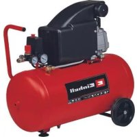
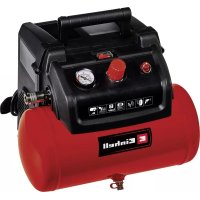
| Product type | Air compressor with pneumatic tool kit |
| Max. working pressure | 6 bar |
| Air flow (tool consumption) | 170 l/min |
| Compressor filling power | 250 l/min |
| Motor power | 2.2 kW |
| Tool rotation speed | 20000 min⁻¹ |
| Recommended hose diameter | 9 mm |
| Required air quality | Clean and oil-mist lubricated air |
| Power supply | Compressed air (via compressor) |
| Intended use | Workshop, DIY, bodywork |
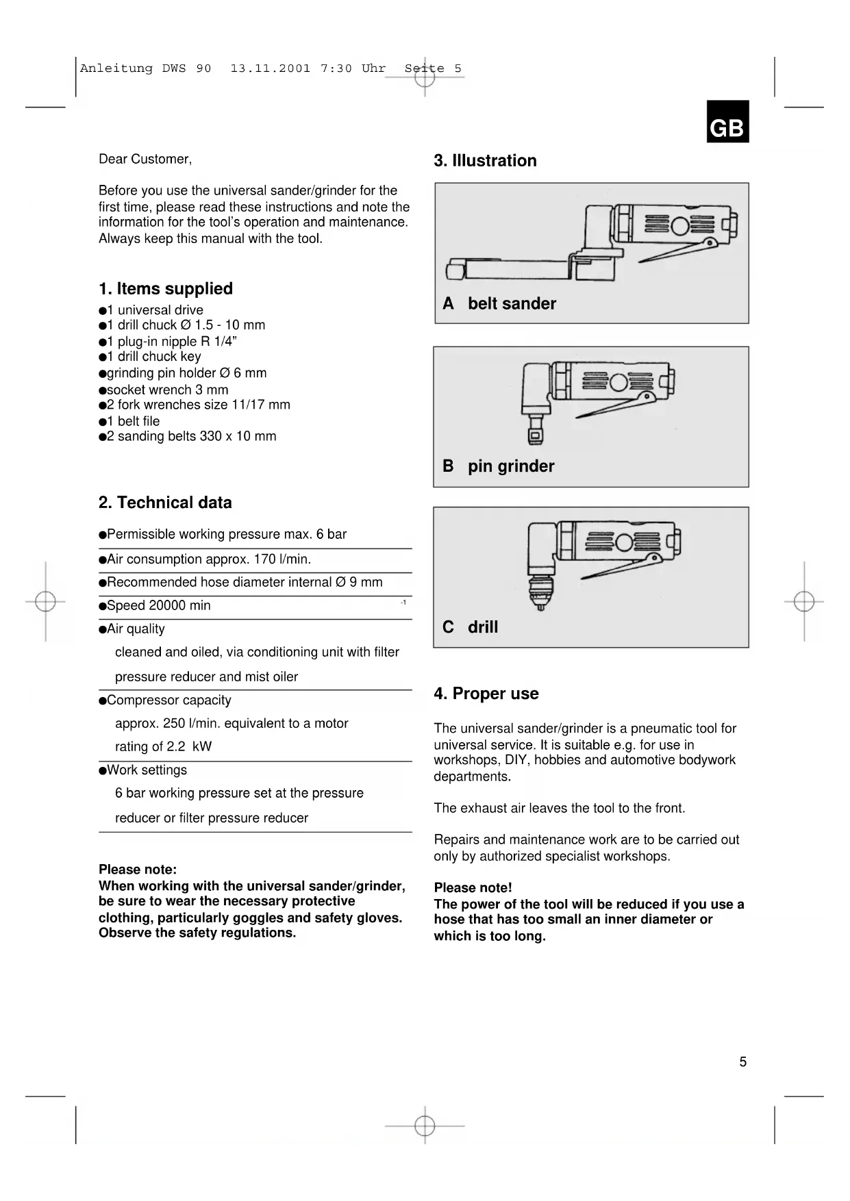
| Kit contents | Universal motor, drill chuck ∅1.5-10 mm, plug-in connector R 1/4", chuck key, grinding wheel holder, fork wrenches, belt file, abrasive belts |
| Maintenance | Regular lubrication with special machine oil (3-5 drops before use) |
| Safety | Wear safety goggles and gloves; do not use oxygen or flammable gas |
| Spare parts | Use only Einhell original parts |
| Warranty | 12 months (material and manufacturing defects) |
Frequently Asked Questions - DWS 90 EINHELL
User questions about DWS 90 EINHELL
0 question about this device. Answer the ones you know or ask your own.
Ask a new question about this device
Download the instructions for your Air compressor in PDF format for free! Find your manual DWS 90 - EINHELL and take your electronic device back in hand. On this page are published all the documents necessary for the use of your device. DWS 90 by EINHELL.
USER MANUAL DWS 90 EINHELL
GB Operating and Maintenance Instructions Pneumatic Workshop Set
natural_image
Pure mechanical part outline without any text, numbers, or symbols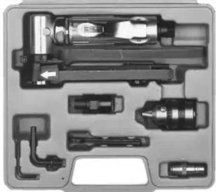
natural_image
Exploded view diagram of a mechanical device showing internal components like gears and shafts (no text or labels)DWS 90

Verehrter Kunde,
natural_image
Line drawing of a handheld electric drill with a screwdriver (no text or symbols)Bohrmaschine
natural_image
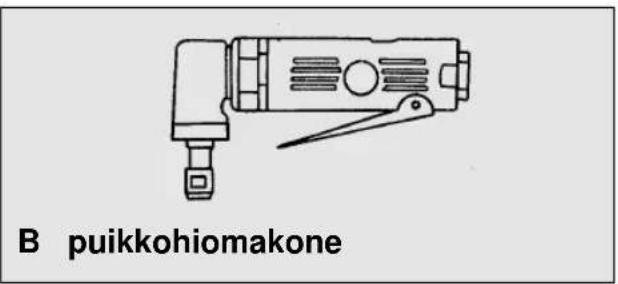
Line drawing of a handheld electrical device with no visible text or symbolsStabschleifer
Before you use the universal sander/grinder for the first time, please read these instructions and note the information for the tool's operation and maintenance. Always keep this manual with the tool.
1. Items supplied
●1 universal drive
●1 drill chuck ∅ 1.5 - 10 mm
●1 plug-in nipple R 1/4"
●1 drill chuck key
●grinding pin holder ∅ 6 mm
- socket wrench 3 mm
●2 fork wrenches size 11/17 mm
●1 belt file
●2 sanding belts 330 x 10 mm
2. Technical data
●Permissible working pressure max. 6 bar
●Air consumption approx. 170 l/min.
●Recommended hose diameter internal ∅ 9 mm
●Speed 20000 min
●Air quality
cleaned and oiled, via conditioning unit with filter pressure reducer and mist oiler
●Compressor capacity
approx. 250 l/min. equivalent to a motor rating of 2.2 kW
●Work settings
6 bar working pressure set at the pressure reducer or filter pressure reducer
Please note:
When working with the universal sander/grinder, be sure to wear the necessary protective clothing, particularly goggles and safety gloves. Observe the safety regulations.
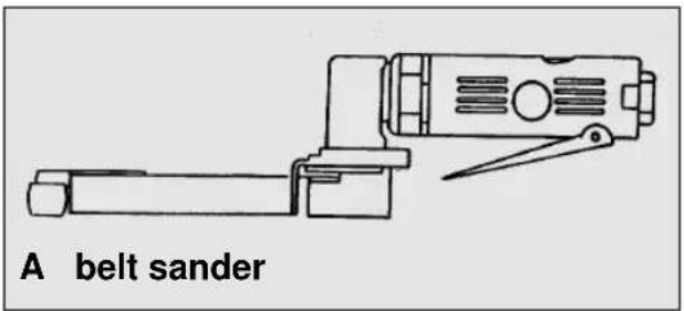
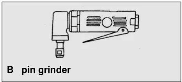
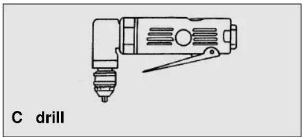
3. Illustration
natural_image
Line drawing of a drill press tool with no text or symbols on the device itself4. Proper use
The universal sander/grinder is a pneumatic tool for universal service. It is suitable e.g. for use in workshops, DIY, hobbies and automotive bodywork departments.
The exhaust air leaves the tool to the front.
Repairs and maintenance work are to be carried out only by authorized specialist workshops.
Please note!
The power of the tool will be reduced if you use a hose that has too small an inner diameter or which is too long.
GB
5. Safety regulations
Take suitable precautions to protect yourself and your environment from potential hazards.
- Never put the universal sander/grinder to any use other than that intended.
Be careful with combustible materials - sparking is possible.
Keep pneumatic tools safe from children.
●Always concentrate while you work. Do not work if you are tired. - Use only a quick-release coupling to connect up the air supply.
- It is imperative to use a pressure reducer to set the working pressure.
●Never use oxygen or combustible gases as an energy source.
●Always disconnect the tool from the air supply before carrying out any repairs or maintenance work.
●Never allow the tool to run unloaded at full idle speed for any length of time.
●Wear the necessary protective clothing, particularly goggles and safety gloves, when working with the universal sander/grinder.
●Watch out for sparks when grinding. Hot flying particles may burn into both soft and hard materials (glass, floor coverings, etc.) or ignite inflammable solids and liquids (hay, saw dust, lacquers, etc.).
Abrasives
- Use only organically bonded abrasive wheels and organically or inorganically bonded grinding pins and small abrasive wheels (wheel ∅ smaller than 20 mm).
- Under no circumstances are you to use abrasive wheels at speeds higher than the speed quoted in rpm by the wheel's manufacturer.
- Allow new abrasive wheels (and all re-mounted abrasive wheels) a running-in period of 30 seconds on the tool on which they are to be used. Operators and other personnel are to stay out of the danger zone during the trial run.
●Never halt an abrasive wheel by pressing on its circumference or face.
●Tighten the lock nut only enough to hold the abrasive wheel securely in place. - Operators are to be thoroughly instructed on how to use the sanding/grinding tool safely.
●Make sure that the air hose connections and hose couplings are tight and that the air pressure is the same as that specified in the instructions.
●Examine grinding pins for signs of damage before using them for the first time and then regularly every day.
●Handle grinding pins and other abrasives carefully. Do not drop. Avoid knocks.
- Make sure the pneumatic motor and the tool's bearings are kept properly lubricated, ideally by means of an oiler in the compressed air line.
●Regular overhauls by a specialist (at least every 3 months, depending on how the tool is used) will ensure troublefree operation and good performance.
- When fitting a grinding pin, be sure to leave a gap of at least 1 cm between the back of the abrasive and the tool lock nut.
6. Putting into operation
Screw the supplied plug-in nipple into the air connection after you have wound 2 to 3 layers of sealing tape around the thread.
Fitting the various attachments
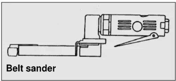
Belt sander
To fit the belt sander attachment you must first take the drill chuck or grinding pin holder off the tool. Screw the belt sander guide roll on the tool and tighten securely with the supplied wrenches. Mount the belt sander attachment and fasten securely with the supplied socket wrench, making sure that the arrow points in the direction of rotation.
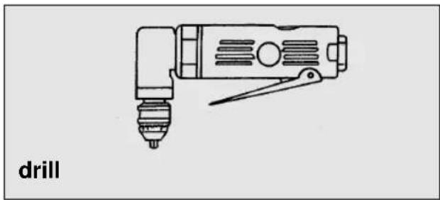
Drill chuck
To fit the drill chuck you must first remove the grinding pin holder or the belt sander attachment with guide roll. Screw the drill chuck on the tool and tighten securely with the supplied wrenches.
natural_image
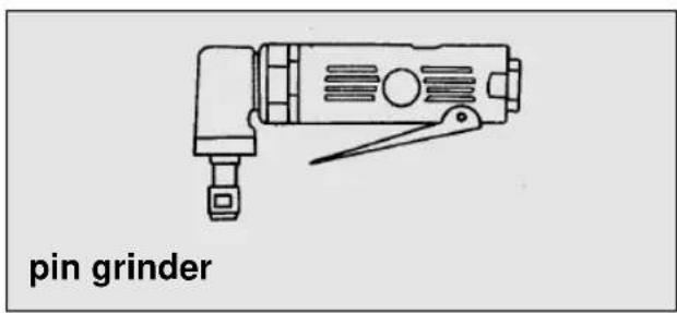
Line drawing of a drill press tool with no text or symbols on the device itselfGrinding pin holder
To fit the grinding pin holder you must first remove the drill chuck or the belt sander attachment with guide roll. Screw the grinding pin holder on the tool and tighten securely with the wrenches.
7. Maintenance and cleaning
Observance of the following maintenance instructions will ensure that this quality tool gives you years of troublefree service.
Regular lubrication is vital for the long-term, reliable operation of your universal sander/grinder. Use only special tool oil for this purpose.
You can choose from the following options for lubricating the tool:
7.1 By mist oiler
A complete conditioning unit includes a mist oiler and is fitted to the compressor.
7.2 By hand
Each time before you use your universal sander/grinder, feed 3-5 drops of special tool oil into the air connection. If the pneumatic tool has not been used for several days, you must feed 5-10 drops of oil into the air connection before you switch on.
Keep your pneumatic tool in dry rooms only.
The warranty does not cover:
●Wearing parts
●Damage caused by an unacceptable level of working pressure.
●Damage caused by unconditioned compressed air.
●Damage caused by improper use or unauthorized tam

Cher client,
natural_image
Line drawing of a mechanical tool with a drill bit and compass (no text or symbols)Boormachine
Stiftslijperopname
natural_image
Line drawing of a mechanical device with a handle and screwdriver (no text or symbols)Stiftslijper
7. Onderhoud
natural_image
Line drawing of a Taladro electric drill (no text or symbols on the device itself)4. Uso previsto
natural_image
Line drawing of a Taladro electric drill (no text or symbols on the device itself)natural_image
Line drawing of a furadeira tool with a drill bit and handle (no text or symbols on the device itself)natural_image
Line drawing of a mechanical device with a lever and handle (no text or symbols)natural_image
Line drawing of a handheld electric drill bit with no text or symbolsFuradeira
natural_image
Line drawing of a handheld electric shaver with lever (no text or symbols)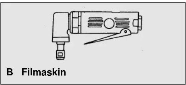
natural_image
Line drawing of a film masker tool with no text or symbols on the device itself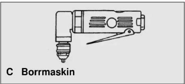

Chuck
4. Käyttötarkoitus
Poraistukka
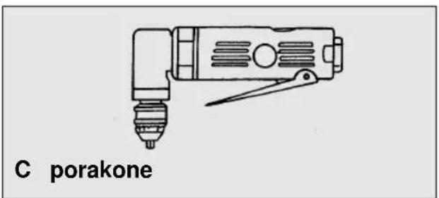
natural_image
Line drawing of a porakone electric drill (no text or symbols on the device itself)natural_image
Line drawing of a Stavsliper tool with no text or symbols on the device itself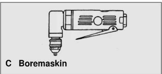
natural_image
Line drawing of a Båndsliper tool with no text or symbols on the diagram itself
Borpatron
natural_image
Line drawing of a Stavsliper tool with no text or symbols on the device itselfnatural_image
Line drawing of a mechanical tool with a base and handle, labeled 'trupávi' at the bottom (no other text or symbols)natural_image
Line drawing of a Trapano electric drill (no text or symbols on the diagram itself)natural_image
Line drawing of a Trapano electric drill (no text or symbols on the device itself)Sede portaasta abrasiva
natural_image
Line drawing of a bandslider device with no text or symbols on the device itselfBorepatron
The guarantee period begins on the sales date and is valid for 1 year.
Responsibility is assumed for faulty construction or material or functional defects.
Any necessary replacement parts an necessary repair work are free of charge.
We do not assume responsibility for consequential damage.
Your customer service partner
F GARANTIE EINHELL
⑤ EINHELL GARANTIBEVIS
DK EINHELL GARANTIBEVIS
Eschenstraße 6 · D-94405 Landau/Isar (Germany)
15 Warwick House Ind. Park, Banbury Road,
Sautham, Warwickshire CV 33 OPS
Technical changes subject to change


- Items supplied
- Technical data
- Please note:
- Illustration
- Proper use
- Please note!
- GB
- Safety regulations
- Abrasives
- Putting into operation
- Fitting the various attachments
- Belt sander
- Drill chuck
- Grinding pin holder
- Maintenance and cleaning
- By mist oiler
- By hand
- The warranty does not cover:
- Stiftslijperopname
- Onderhoud
- Uso previsto
- Chuck
- Käyttötarkoitus
- Poraistukka
- Borpatron
- Sede portaasta abrasiva
- Borepatron
- F GARANTIE EINHELL
- ⑤ EINHELL GARANTIBEVIS
- DK EINHELL GARANTIBEVIS
Brand : EINHELL
Model : DWS 90
Category : Air compressor