
30050 W - Air compressor EINHELL - Free user manual and instructions
Find the device manual for free 30050 W EINHELL in PDF.
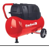
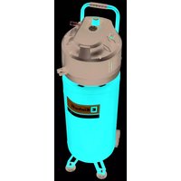
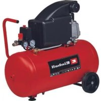
| Product type | Piston air compressor |
| Model | 30050 W |
| Brand | Einhell |
| Motor power | 1.5 kW (2.0 HP) |
| Compressor speed | 1700 rpm |
| Maximum working pressure | 10 bar |
| Pressure tank volume | 50 liters |
| Effective flow rate at 6 bar | 160 l/min |
| Aspirated flow | 300 l/min |
| Power supply | 230 V ~ 50 Hz |
| Recommended fuse | 16 A |
| Motor protection type | Thermal circuit breaker (overcurrent) |
| Recommended motor oil | SAE 15W/40 or equivalent |
| Oil capacity | Approx. 0.6 liter |
| Oil change interval | First oil change after 100 h, then every 500 h |
| Air filter cleaning | Every 300 operating hours |
| Cut-in pressure (factory setting) | 6 bar |
| Cut-out pressure (factory setting) | 10 bar |
| Overflow valve | Set to maximum tank pressure |
| Air connection | Quick coupling with instant locking |
| Item number | 40.251.00 |
| Identification number | 90013 |
| Additional features | Suppressed according to CE 82/499 EEC |
Frequently Asked Questions - 30050 W EINHELL
User questions about 30050 W EINHELL
0 question about this device. Answer the ones you know or ask your own.
Ask a new question about this device
Download the instructions for your Air compressor in PDF format for free! Find your manual 30050 W - EINHELL and take your electronic device back in hand. On this page are published all the documents necessary for the use of your device. 30050 W by EINHELL.
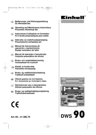
USER MANUAL 30050 W EINHELL
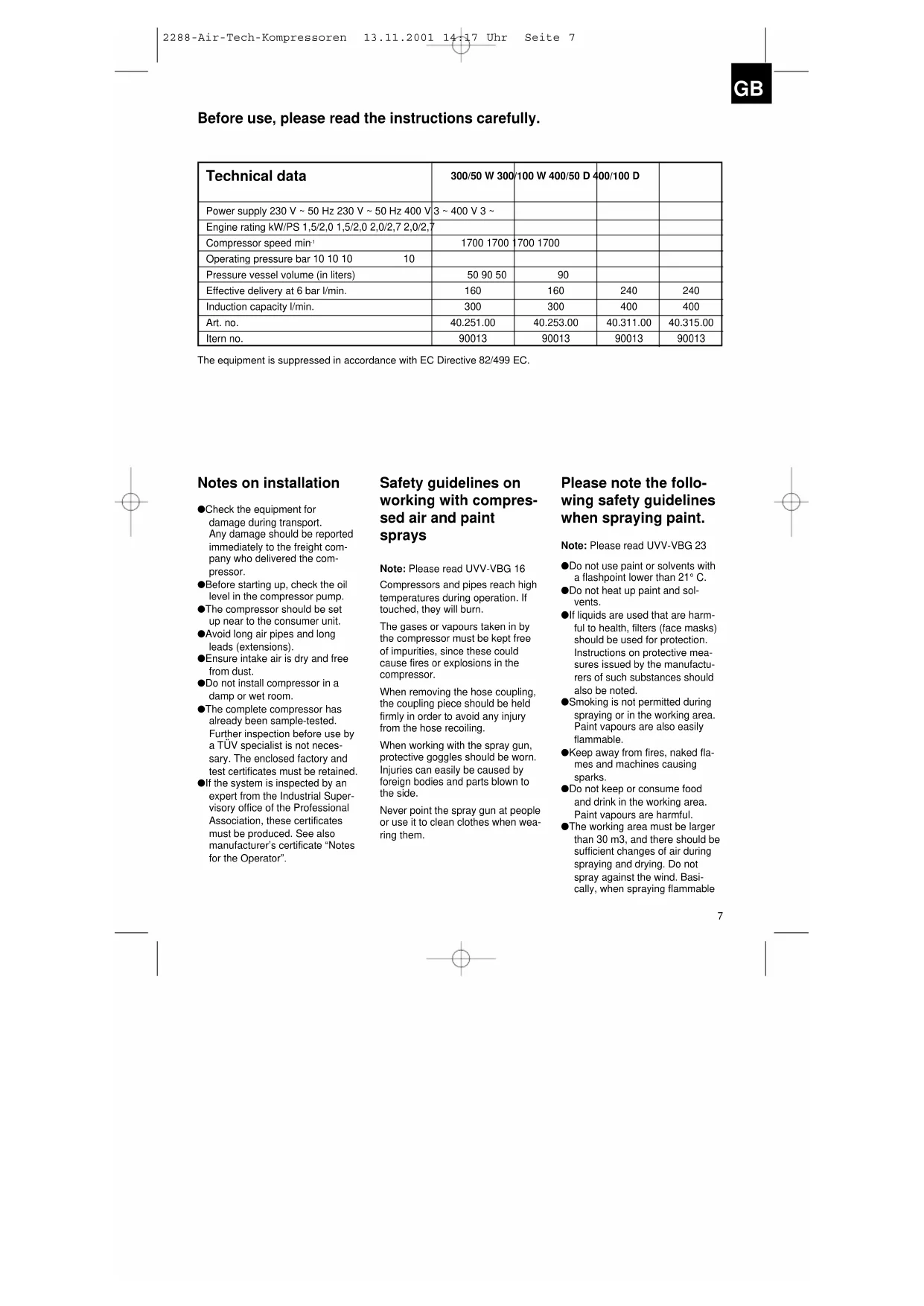
Before use, please read the instructions carefully.
| Technical data | 300/50 W 300 | 100 W 400/50 D | 400/100 D | |
| Power supply 230 V ~ 50 Hz 230 V ~ 50 Hz 400 V | 3 ~ 400 V 3 ~ | |||
| Engine rating kW/PS 1,5/2,0 1,5/2,0 2,0/2,7 2,0/2,7 | ||||
| Compressor speed min ^1 | 1700 1700 | 1700 1700 | ||
| Operating pressure bar 10 10 10 | 10 | |||
| Pressure vessel volume (in liters) | 50 90 50 | 90 | ||
| Effective delivery at 6 bar l/min. | 160 | 160 | 240 | 240 |
| Induction capacity l/min. | 300 | 300 | 400 | 400 |
| Art. no. | 40.251.00 | 40.253.00 | 40.311.00 | 40.315.00 |
| ltern no. | 90013 | 90013 | 90013 | 90013 |
The equipment is suppressed in accordance with EC Directive 82/499 EC.
Notes on installation
- Check the equipment for damage during transport. Any damage should be reported immediately to the freight company who delivered the compressor.
●Before starting up, check the oil level in the compressor pump.
●The compressor should be set up near to the consumer unit.
●Avoid long air pipes and long leads (extensions).
●Ensure intake air is dry and free from dust.
●Do not install compressor in a damp or wet room.
●The complete compressor has already been sample-tested. Further inspection before use by a TÜV specialist is not necessary. The enclosed factory and test certificates must be retained. - If the system is inspected by an expert from the Industrial Supervisory office of the Professional Association, these certificates must be produced. See also manufacturer's certificate "Notes for the Operator".
Safety guidelines on working with compressed air and paint sprays
Note: Please read UVV-VBG 16
Compressors and pipes reach high temperatures during operation. If touched, they will burn.
The gases or vapours taken in by the compressor must be kept free of impurities, since these could cause fires or explosions in the compressor.
When removing the hose coupling, the coupling piece should be held firmly in order to avoid any injury from the hose recoiling.
When working with the spray gun, protective goggles should be worn. Injuries can easily be caused by foreign bodies and parts blown to the side.
Never point the spray gun at people or use it to clean clothes when wea-ring them.
Please note the following safety guidelines when spraying paint.
Note: Please read UVV-VBG 23
- Do not use paint or solvents with a flashpoint lower than 21^ .
●Do not heat up paint and solvents. - If liquids are used that are harmful to health, filters (face masks) should be used for protection. Instructions on protective measures issued by the manufacturers of such substances should also be noted.
●Smoking is not permitted during spraying or in the working area. Paint vapours are also easily flammable. - Keep away from fires, naked flames and machines causing sparks.
●Do not keep or consume food and drink in the working area. Paint vapours are harmful.
●The working area must be larger than 30 m3, and there should be sufficient changes of air during spraying and drying. Do not spray against the wind. Basically, when spraying flammable
GB
or dangerous goods, the provisions of the local police authorities should be complied with.
●Do not process media such as white spirit, butyl alcohol and methylene alcohol anywhere near the PVC pressure hose (reduced working life).
Starting up
Fitting the rotor wheels:
To fit the wheels, you will need a hammer and a piece of piping with an internal diameter of 25 mm or a 24 mm socket wrench.
First, knock a rapid fixing cap onto one side of the axle pipe. It should be about 8 mm onto the axle pipe. Take care to affix the cap the right way round. In order for the wheel to turn on the axle properly over a long period of time, grease the running surfaces on the axle with lubricating grease.
Now place a wheel, domed side outwards, onto the axle and push it from one side of the axle stay out to the other side of the axle stay. Now grease the other side of the axle too and place the wheel on it. Finally, knock the second rapid fixing cap onto the axle. Do not fix the rapid fixing cap too tightly, or the wheels will slip. Finally, affix the cap covers onto both wheels.
Operation of pressure vessels in accordance with the Order on Pressure Vessels (§ 13)
- Anyone who operates a pressure vessel shall keep it in a proper condition, run it properly, monitor it, undertake the necessary maintenance and repair work immediately and take all the safety measures necessary depending on the circumstances.
- The Supervisory Authority may prescribe the monitoring measures that are required in individual cases.
- A pressure vessel may not be operated if it shows any defects which could endanger employees or third parties.
- If pressure vessels in Groups II, IV, VI and VII show damage to pressure-bearing walls which cause them to be shut down in accordance with § 13 Para.3, the operator must inform the expert and agree with him on the necessary steps to be taken.
Hose coupling:
Twist the hose coupling, which already has a sealing strip attached, onto the back of the boiler with an SW 22 open-ended wrench.
Transport handle:
Loosen the rear fixing screws of the motor (pressure switch side). Push the handle into the opening on the installation plate (front end) until it is about 10cm through the slide rail under the installation plate. Then tighten both the motor screws again.
- Screw the rubber buffer(s) provided to the support foot.
Installation of air filter
Twist the threaded rod with the short thread into the opening of the compressor head and tighten it a little with pliers.
Then place the air filter housing, into which the filter cartridge has already been inserted, over the threaded rod into the opening of the compressor.
Then secure the filter on the threaded rod with the wing nut.

natural_image
Blank white image with a thin black border (no text, symbols, or markings)Important note:
Make sure that direction of rotation is correct – see directional arrow on belt guard or fan propeller.
The three-phase motor is protected against winding damage by an overload circuit breaker in the motor terminal box in the event of phase failure, overloading and short-circuiting. It is switched back on by pressing the rocker switch on the overload circuit breaker.
Important:
Unplug from the mains before carrying out maintenance, repair and inspection work.
Care and maintenance
●Condensation water:
The condensation water is to be let out every day by opening the drainage valve (underside of pressure vessel).
●Safety valve:
The safety valve is set at the highest permissible pressure of the pressure vessel. No-one is allowed to adjust the safety valve or to remove its lead seal.
The safety valve should be operated from time to time to ensure that it works properly when needed.
For this, turn the knurled screw to the left until the compressed air can be heard blowing off. Then turn the knurled screw as far as possible to the right and tighten by hand.
●Check the oil level regularly:
The oil level must be visible in the inspection glass between the upper and the lower marks. Oil change: recommended oil: SAE 15W/40 or equivalent. The first batch of oil should be changed after 100 operating hours.
After this, the oil should be drained off and replaced with new oil every 500 operating hours.
GB
●Changing the oil:
Switch the motor off and unplug from the mains supply. After releasing any air pressure, unscrew the plastic oil drainage screw on the compressor pump. To stop the oil running out everywhere, hold a small metal trough underneath so that you can collect the oil in a container. Dispose of the used oil at a suitable used oil collection centre.
Once the oil has drained out, tighten the plastic screw again. Take off the plastic lid over the vent shaft and pour in the oil until the oil level can be seen in the glass between the two marks. The quantity of oil is approx. 0.5 litres. Then press the lid onto the vent shaft again.
Fitting the filter pressure reducer or combined maintenance unit
To fit the filter pressure reducer R 1/4" Art. no. 41.342.00 and combined maintenance unit R1/4" Art.no. 41.350.01:
Using an SW 22 open-ended wrench, remove the quick coupling from the pressure switch. Seal the R1/4" shoulder nipple on both sides with about 3-4 layers of sealing tape and insert this into the right hand side of the filter pressure reducer, seen from the front.
●Cleaning the intake filter cartridge
The intake filter prevents dust and dirt from being taken in. This filter cartridge must be cleaned at least every 300 operating hours. A blocked intake filter considerably reduces the efficiency of the compressor. The filter cartridge can be removed by unscrewing the instake filter housing. Wash out the filter with benzine, blow dry and re-insert.
Spare filters can be obtained from our Customer Services Department.
●Tightening the V belt:
Loosen the four motor fixing screws and push the motor backwards with a wedge of wood between the pump and the motor until the V belt is tight to the extent that it can be pressed down about 1-2 cm with the fingers.
Then screw the filter pressure reducer by hand into the opening of the pressure regulator as shown on the drawing. Then insert the quick coupling, after resealing it, into the right hand sie of the filter pressure reducer.
The R 1/4" combined maintenance unit is fitted to the pressure switch as shown in the drawing. For this, unscrew the pressure manometer from the pressure switch and screw the combined maintenance unit into this opening, as described before.
Now unscrew the quick coupling from the pressure switch. Screw in the manometer in place of the quick coupling and screw in the quick coupling into the opening of the
combined maintenance unit. Follow the drawing for this.
The R 3/8" filter pressure reducer and the R 3/8" combined maintenance unit are basically fitted at the boiler outlet. For this, unscrew the quick coupling and attach the parts with a R 3/8" shoulder nipple. The quick coupling is fixed to the filter
Using an 8 mm socket spanner, adjust the differential pressure P on screw 1.
The differential pressure and the cut-out pressure are increased by turning to the right. The differential pressure is reduced by turning to the left, and the cut-out pressure is therefore lower.
Screw 2 is used to adjust the cut-in and cut-out pressure P. The cut-in and cut-out pressure is increased by turning to the right. The cut-in and cut-out pressure is reduced by turning to the left.
Pressure switch
pressure reducer or the combined maintenance unnit. All screw connections are sealed with approx. 3-4 layers of sealing tape before they are tightened up. For professional use, you can also run the Einhell AIRTECH Center on your compressor. For information on assembly and connection to the compressor, please read the instructions for the AIRTECH Center.
1 Pressure switch
2 On-off switch
3 Mains power supply
4 Indicator for vessel pressure
5 Safety valve
6 Single-hand quick coupling
7 Locking screw
Setting the pressure switch
The pressure switch is set at the factory.
Cut-in pressure: 6 bar
Cut-out pressure: 10 bar
To adjust the pressure difference: Remove the cover from the pressure switch (unscrew the locking screw).
Possible causes of breakdown
which cause overloading of the motor and thus activate the overload circuit breaker:
●mains power supply too high
●ambient temperature too high and inadequate air supply
● faulty compressor valve or leaking nonreturn valve
●oil level at minimum, connecting rod bearings stiff.
Switch on three-phase and AC motors after leaving them to cool down. Do not touch hot components and pipes.
natural_image
Empty white square with a thin gray border (no text or symbols)Viktigt!
The company reserves the right to make technical changes.
- Notes on installation
- Safety guidelines on working with compressed air and paint sprays
- Please note the following safety guidelines when spraying paint.
- GB
- Starting up
- Fitting the rotor wheels:
- Operation of pressure vessels in accordance with the Order on Pressure Vessels (§ 13)
- Hose coupling:
- Transport handle:
- Installation of air filter
- Important note:
- Important:
- Care and maintenance
- ●Condensation water:
- ●Safety valve:
- ●Check the oil level regularly:
- ●Changing the oil:
- Fitting the filter pressure reducer or combined maintenance unit
- ●Cleaning the intake filter cartridge
- ●Tightening the V belt:
- Pressure switch
- Setting the pressure switch
- Possible causes of breakdown
- Viktigt!
Brand : EINHELL
Model : 30050 W
Category : Air compressor