FX-KSF700 - Sharpener Fuxtec - Free user manual and instructions
Find the device manual for free FX-KSF700 Fuxtec in PDF.
| Product type | Electric chain sharpener |
| Brand | Fuxtec |
| Model | FX-KSF700 |
| Power supply voltage | 230 V ~ 50 Hz |
| Motor power | 65 W |
| Rotation speed | 7 000 rpm |
| Sharpening angle | 35° right to left |
| Grinding wheel diameter | 100 mm |
| Grinding wheel bore | 22.2 mm (7/8\") |
| Dimensions (L × W × H) | 155 × 315 × 190 mm |
| Weight | 1.45 kg |
| Intended use | Sharpening chainsaw chains |
| Mounting | On workbench (2 mounting holes of 6 mm) |
| Safety | Wheel cover, trigger switch with emergency stop |
| Sound pressure level (LpA) | 75 dB(A) |
| Sound power level (LwA) | 86 dB(A) |
| Certifications | CE, EU conformity (directive 2006/42/EC) |
| Maintenance | Regular cleaning; replace wheel if diameter < 7.65 cm |
| Spare parts | Original FUXTEC grinding wheels (ref. 100 × 3.2 mm) |
| Recycling | Do not dispose of with household waste; take to recycling center |
Frequently Asked Questions - FX-KSF700 Fuxtec
User questions about FX-KSF700 Fuxtec
0 question about this device. Answer the ones you know or ask your own.
Ask a new question about this device
Download the instructions for your Sharpener in PDF format for free! Find your manual FX-KSF700 - Fuxtec and take your electronic device back in hand. On this page are published all the documents necessary for the use of your device. FX-KSF700 by Fuxtec.
USER MANUAL FX-KSF700 Fuxtec
natural_image
Illustration of a welding torch with a clamping device, rendered in gold outline against black background (no text or symbols)
natural_image
Orange icon of a person reading a book on black background (no text or symbols)
natural_image
Icon of a hand pointing at an open book with horizontal lines representing text (no actual text or symbols)DEUTSCHE VERSION....6
VERSION FRANCAISE....19
POLSKA WERSJA JEZYKOWA....113
DEUTSCHE VERSION....6
- Specifications 47
- Safety Warnings and Notices for Electric Chain Sharpeners....47
- Additional security warnings....49
- Assembly 50
- Operation 51
- Maintenance ....54
- Parts List ....54
- Assembly drawing 56
- Disposal 57
- EU declaration of conformity ....58
VERSION ESPANOLA 59
POLSKA WERSJA JEZYKOWA....113
natural_image
Close-up of a mechanical tool with transparent grip and metal base (no visible text or symbols)
natural_image
Close-up of a mechanical device with a transparent dome and metal bracket (no visible text or symbols)6mm
Abb. 2
natural_image
Close-up of a mechanical clamp device with a transparent cover and metal bracket (no visible text or symbols)Sockel (#36)
natural_image
Close-up of a mechanical assembly with a hand operating a workpiece (no visible text or symbols)natural_image
Close-up of a mechanical device with a circular component and attached bracket (no visible text or symbols)natural_image
Close-up of a mechanical assembly with a textured metal strip and clamping tool (no visible text or symbols)natural_image
Close-up of a mechanical device with a circular component and attached bracket (no visible text or symbols)Abb. 11
natural_image
Close-up of a robotic arm with mechanical components and no visible text or symbolstext_image
Exploded view diagram of a mechanical assembly with numbered parts for identification9. Entsorgung

Leinfelden-Echterdingen, Germany
natural_image
Mechanical tool with transparent casing and metal base, no visible text or symbolsVotre nouvel
natural_image
Mechanical device with a transparent dome and mechanical clamp, labeled 'Fig. 1' (no readable text or symbols on the device itself)natural_image
Mechanical device with transparent casing and metal base, labeled Fig. 2 (no visible text or symbols on the device itself)Piédestal (#36)
natural_image
Close-up of a robotic arm with chains and mechanical components (no visible text or symbols)Fig. 8
natural_image
Close-up of a mechanical device with a circular component and attached lever mechanism (no visible text or symbols)Fig. 9
natural_image
Close-up of a mechanical assembly with a textured fabric and metal clamping tool (no visible text or symbols)natural_image
Close-up of a mechanical device with a circular component and a tool, placed on tiled floor (no visible text or symbols)
natural_image
Close-up of a robotic arm gripping a mechanical component (no visible text or symbols)Fig. 11
text_image
Exploded view diagram of a mechanical assembly with numbered parts for identification19. Recyclage

natural_image
Mechanical tool with transparent casing and metal base, no visible text or symbolsIl tuo nuovo
natural_image
Medical device labeled Figura 1 showing a mechanical assembly with no visible text or symbols on the device itself.Foro passante da 6
natural_image
Experimental setup with a transparent dome-shaped device and mechanical components (no visible text or symbols)Piedistallo (#36)
natural_image
Close-up of a hand operating a mechanical tool with chains and a vise (no visible text or symbols)natural_image
Close-up of a mechanical device with a circular component and attached lever mechanism (no visible text or symbols)natural_image
Close-up of a mechanical assembly with a textured fabric and metal clamping tool (no visible text or symbols)natural_image
Close-up of a mechanical device with a coiled component and a tool, no visible text or symbolsnatural_image
Close-up of a robotic arm gripping a mechanical component (no visible text or symbols)26. Manutenzione
text_image
Exploded view diagram of a mechanical assembly with numbered parts for identification29. Disposizione

| Connection | 230V - 50Hz |
| Engine power P1 | 65 W |
| RPM | 7000 |
| Table/Vise Angle | 35 degrees Right to Left |
| Pick-up diameter | 22.2 mm |
| Grinding wheel dimensions | 100 x 3.2 mm |
| Total dimensions | 155 x 315 x 190mm |
| Weight | 1.45 kg |
Keep this instruction manual.
You will need the instructions for the safety instructions, precautions, assembly, use, maintenance and the list of individual parts. Store the instruction manual in a safe and dry place for later use.
Intended use
The device is intended exclusively for sharpening saw chains. Before commissioning, the device must be permanently mounted on a workbench or similar surface. Only use the saw chain sharpener if you can fully assess all functions and carry them out without restriction or have received appropriate instructions. Taking into account the technical data and safety instructions.
This device may only be used as directed. In the event of non-compliance with the provisions, from the generally applicable regulations and the provisions of this manual. The manufacturer cannot be held responsible for damages.
Please note that our device has not been designed for commercial use.
32. Safety Warnings and Notices for Electric Chain Sharpeners
CAUTION: When using this device, all safety instructions should always be followed to reduce the risk of injury to you or damage to the device.
Read the complete instructions before using the device!
- Keep your workspace clean. Dirty work areas can promote injuries.
-
Consider the environment of your workspace. Do not use machinery or power tools in a damp or wet environment. Do not expose the device to rain. The work area must be well lit. Do not use electrical appliances near flammable gas or liquids.
-
Keep children away. Children must not be in the work area under any circumstances, under no circumstances should children operate the machines, equipment or extension cords.
- Keep the devices safe. When not in use, the equipment must be stored in a dry place to prevent rust. Always lock the devices away and keep them out of the reach of children.
- Use the right tool for the task. Do not try to do the work of a large industrial tool with a small tool or accessory. There are certain applications for which the tool is designed. It will do the job better and more safely if it is used for the task developed. Do not modify the tool or use it for work for which it is not intended.
- Wear appropriate clothing. Do not wear loose clothing or jewelry that could get caught in the moving parts of the device.
Protective and non-electrically conductive clothing and non-slip shoes are recommended for working with this device. Keep hair, jewelry, or loose clothing away from moving parts. These can be recorded by them..
-
Use eye and ear protection. Always wear approved impact goggles and wear a face shield when producing metal chips or wood chips while using the machine.
-
Do not reach over the device. Keep a firm footing and balance at all times. Do not reach over or into running machines.
-
Take care of your device carefully. Keep your tools sharp and clean for better performance. Follow the instructions to lubricate and change accessories. Check the tool cables regularly. In the event of damage, have them repaired exclusively by authorized technicians. The appliance must be kept clean, dry and free of oil or grease at all times.
-
Avoid unintentional starting. Make sure the switch is in the off position before plugging in the device.
-
Stay alert. Look carefully at what you are doing, use your mind. Do not use tools or equipment when you are tired.
-
Check the device for damaged parts. Before using the device, you should carefully inspect any part that appears to you to be damaged and make sure that it is working properly and can perform its intended function. Check the alignment and fastening of moving parts and any other operationally necessary operations that could interfere with operation for breakage or other damage. Any damaged part should be professionally repaired or replaced by an authorized technician. Do not use the appliance if any switch cannot be turned on or off.
-
Protect yourself against electric shock. Avoid contact with ground surfaces such as pipes; heaters, stoves and refrigerators.
-
Assembly of spare parts and accessories. Only use identical spare parts during maintenance. With the installation of other parts, the warranty expires. Only use accessories that have been developed for the device.
-
Do not use the device under the influence of alcohol, drugs or medication. Read the warnings of your medication to assess whether your reflexes for using the device are limited. If in doubt, refrain from using the device.
-
Use the right size and type of extension cord. If you need an extension cord, pay attention to the design and usability. Otherwise, the extension cord could melt, catch fire, or cause damage to the electrical system of the device. This tool requires the use of a 0-10 amp capacity extension cord
with a wire size of 18 AWG (up to 15m in length). Longer extension cords require higher AWG rating. If you use the device outdoors, only use cables that are approved for outdoor use.
- Maintenance. For your safety, maintenance and servicing should be carried out by an authorized technician.
- Never use the electric chainsaw sharpener near flammable material. Note: The performance of this tool (when powered by mains voltage) may vary depending on fluctuations in local mains voltage. The use of extension cords can also affect the performance of the tool.
Caution: The warnings, hints, and instructions referred to in this guide do not cover all possible conditions and situations that may occur. The operator of the device must understand that human behavior and other hazards are factors that cannot be influenced by the product and manufacturer, but the operator of the device must be aware of.
33. Additional security warnings
Grinding Wheels Warnings
- Do not use a grinding wheel that is cracked, broken or worn. You can check the disc for invisible cracks by hanging the disc from the central hole and tapping against it with a non-metallic object. (BSPW with a screwdriver handle) If it is in good condition, you will hear a metallic sound. A dull sound indicates a crack or fracture.
- Only use original FUXTEC grinding wheels with a hub diameter of 22.2mm (7/8"). Do not attempt to change or modify the mounting hole of the grinding wheel of a different size to make it fit.
- Don't over-tighten the nut (#3). Simply put them on with your hand. Over-tightening or over-tightening can cause the wheel to break.
- Never use the chain sharpener without the grinding wheel cover (#2) in the correct position.
- Always check the grinding wheel (#5) by running it for one minute without contact with the chain.
- Stay away from the rotating disc and make sure that no person is standing too close to it, or in the direction of the disc rotation.
- If the grinding wheel vibrates, turn off the machine immediately and check that it is firmly mounted and has no damage.
- Never try to stop the grinding wheel by hand, even if you are wearing protective gloves. The grinding wheel would cut through the gloves and seriously injure your hand.
- Never use the device without the grinding wheel mounted.
- The permitted speed and speed of replacement grinding wheels must correspond exactly to the specified speed of the device.
Warning!! This device is designed to sharpen chains of chainsaws. Do not try to sharpen other tools or any other objects with it.
Unwrap:
When unpacking the device, make sure that all the parts listed on page 9 are present.
34. Assembly
-
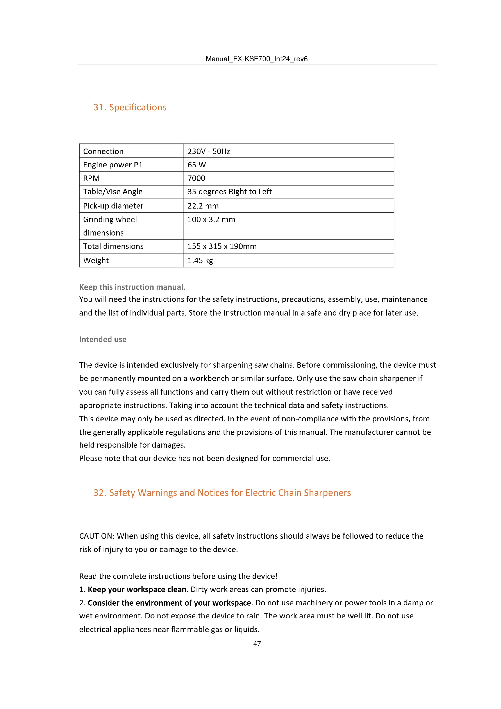
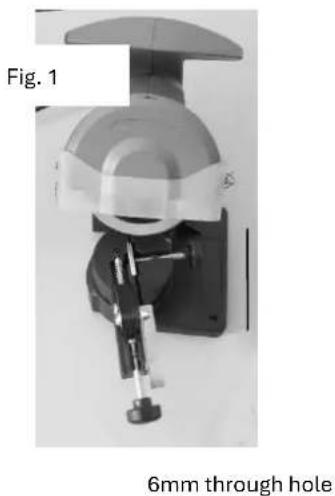
If you are installing the sharpener on a workbench, make sure the ratchet wheel (#40) is accessible. (See Fig. 1)
-
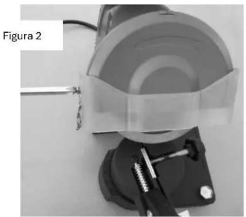
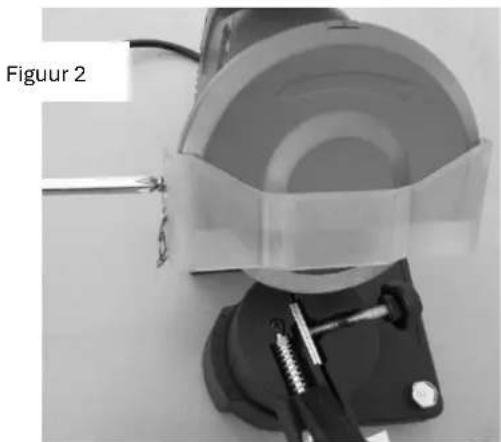
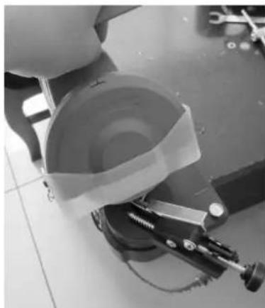
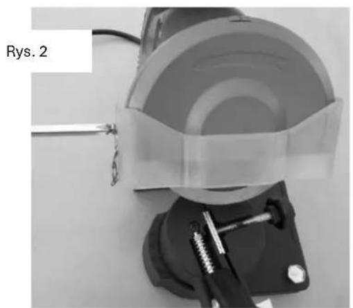
Screws (screws not included) Attach the base of the device directly to the workbench, using the two 6mm holes on the base (#36). The workbench must have a solid surface that can withstand the weight of the sharpener as well as the other tools. See Fig. 2.
natural_image
Mechanical device with a 6mm through hole, shown in technical view (no text or symbols on the device itself)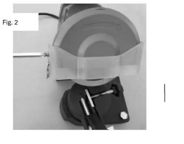
natural_image
Close-up of a mechanical device with transparent casing and attached clamping base (no visible text or symbols)Pedestal (#36)
Warning! Always unplug the machine before changing the grinding wheel or making any other adjustments.
Mounting the grinding wheel:
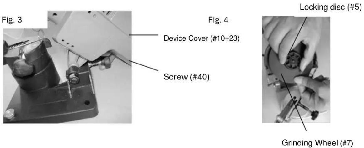
Figure 3 and Figure 4 are related to the assembly drawing on page 10.
Open the motor housing (#10+23) and set it in the up position by tightening the screw (#40). Remove the two screws that hold the grinding wheel cover (#2). Put the cover aside.
Loosen the top locking disc (#5) in place.
Install the new disc on the pressure plate (#4), make sure everything fits properly.
Note: Do not use a grinding wheel that is cracked, broken, or worn. You can check the disc for invisible cracks by hanging the disc from the central hole and tapping against it with a non-metallic object. (BSPW with a screwdriver handle) If it is in good condition, you will hear a metallic sound. A dull sound indicates a crack or fracture.
Put the grinding wheel cover back on (#5).
Loosen the screw (#40) and lower the upper housing.
Never use the tool in the correct position without the grinding wheel cover.
text_image
Fig. 3 Fig. 4 Device Cover (#10+23) Screw (#40) Locking disc (#5) Grinding Wheel (#7)35. Operation
Warning! Always pull the plug of the device while making adjustments to sharpen the chain.
Regarding the assembly drawing on page 10 and the various pictures.
Note: Open the upper housing while adjusting the chain.
- Clean the chain before sharpening. Wash them with non-flammable solvent. Do not use gasoline to clean or dry the chain.
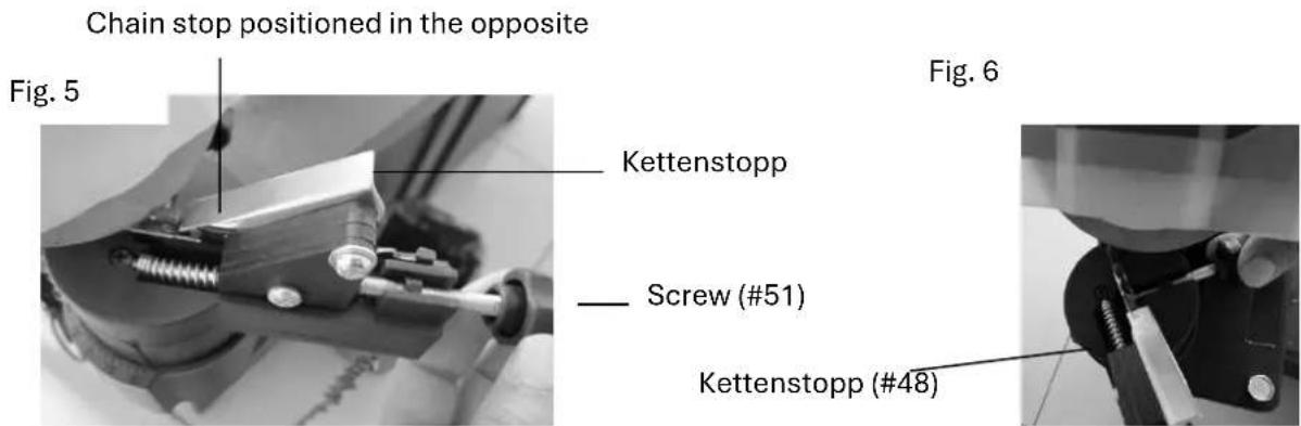
- Lift the chain stop (#48) and attach the chain to the fixing plate (#32). See Fig. 6.
- Lower the chain stop (#48) so that the chain link you start with is correctly positioned. See Fig. 5.
text_image
Chain stop positioned in the opposite Fig. 5 Kettenstopp Screw (#51) Kettenstopp (#48) Fig. 6-
Look at Figures 5 and 6. Loosen the screw (#40) to rotate the housing. Rotate the housing to the desired number of degrees that is needed. Necklaces come in different sizes and with different angles for sharpening. Check the chain manufacturer's instructions to determine which angle you need to sharpen the chain. Once you have adjusted the angle, you need to tighten the screw (#40).
-
Lower the motor housing (#10+23) so that the grinding wheel (#7) brushes the chain teeth.
-
Hold the position while tightening the screw (#40) so that the washer lowers only at this point.
See Fig. 7.
- Depending on the amount of material you want to remove, fasten or loosen the screw (#51) and tighten the nut. See Fig.5. Screw 51 has a nut I that can be used to adjust how much material is removed. Once you have set the nut, tighten the bolt (#51) all the way.
Fig. 7
Screw (#40)

natural_image
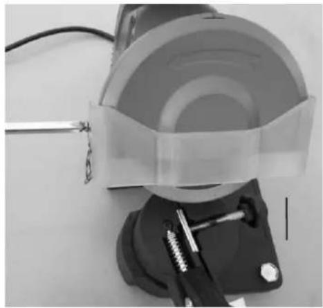
Close-up of a hand operating a mechanical tool with a spring and chain, no visible text or symbols- Attach the chain to the fixing plate (#48) by operating the screw (#49) (as shown in Fig. 8).
The screw (49) should be seated in such a way that it can be easily loosened or tightened.
You'll have to loosen and tighten them every time you move to the next chain link.
Fig. 8
natural_image
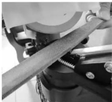
Close-up of a mechanical device with a circular component and attached bracket (no visible text or symbols)- If the chain has already been sharpened several times, limit the chain depth and the chain links must be filed down with a flat file (not included).
See Fig. 8 & 9 .File each limb down so that it is lower than the cutting tooth.
Fig. 9
natural_image
Close-up of a mechanical assembly with a textured rod and metal clamped components (no visible text or symbols)- Put on your protective clothing and make sure the immediate area is free of people.
-
Plug in the cable (#21) and press the green button on the trigger (#18) to start the machine.
-
Slowly lower the grinding wheel as described in
Fig. 10. If you find any errors in your settings, turn off and unplug the device before correcting your settings.
Note: Uniform sharpness is achieved by continuous and smooth contact between the grinding wheel and the teeth. Don't stop too long at each tooth.
- After sharpening a tooth, turn off the machine.
Open the motor housing (#10+23), loosen the bolt (#52) and move the chain so that the next link chain is positioned at the chain stop (#48) and tighten the bolt (#52) again. Turn the machine back on and sharpen the next tooth. Repeat this process until you have sharpened all the teeth possible at this angle.
Fig. 10
natural_image
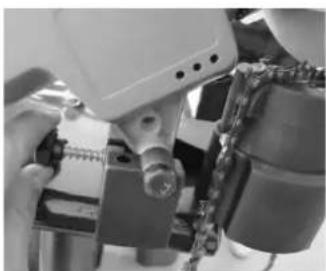
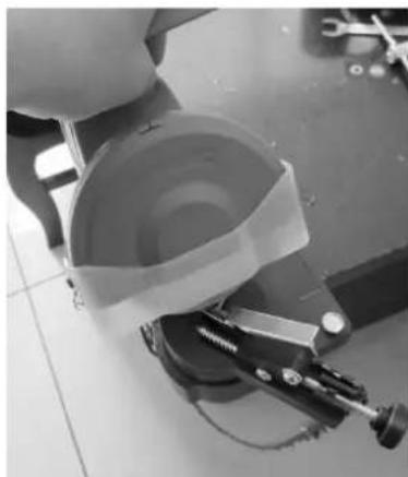
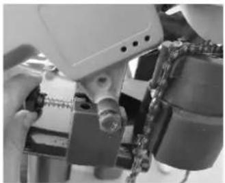
Close-up of a mechanical device with a coiled component and a tool, no visible text or symbols- After sharpening all the teeth of the chain, turn off the machine by pressing the red button (#25) and pull the plug.
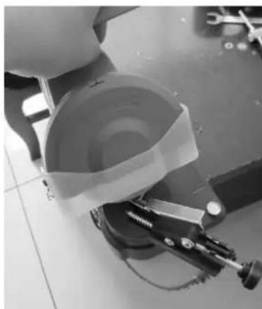
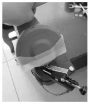
- Loosen the ratchet wheel and set the angle so that the first tooth that has not yet been sharpened is positioned opposite the screw and is fixed as explained on page 6. Shown in Fig. 11.
- Based on the first half of the chain, make sure the motor housing is lowered (#10+23) and the grinding wheel (#7) touches the chain teeth. Follow all the steps on page 6 to double-check everything before plugging in and restarting the machine.
Fig. 11
natural_image
Close-up of a robotic arm with mechanical components and wiring (no visible text or symbols)Don't forget to turn off the machine and unplug it when making adjustments of any kind.
- After repeating all the sharpening steps on page 7, your chain is ready to be mounted on the chainsaw again.
36. Maintenance
- Keep the sharpener clean and free from dust, metal abrasion and dirt.
- Check the grinding wheel for damage before each use. Do not use a grinding wheel that is cracked, broken or worn. You can check the disc for invisible cracks by hanging the disc from the central hole and tapping against it with a non-metallic object. (BSPW with a screwdriver handle) If it is in good condition, you will hear a metallic sound. A dull sound indicates a crack or fracture.
- Replace the grinding wheel if the diameter is less than 7.65cm.
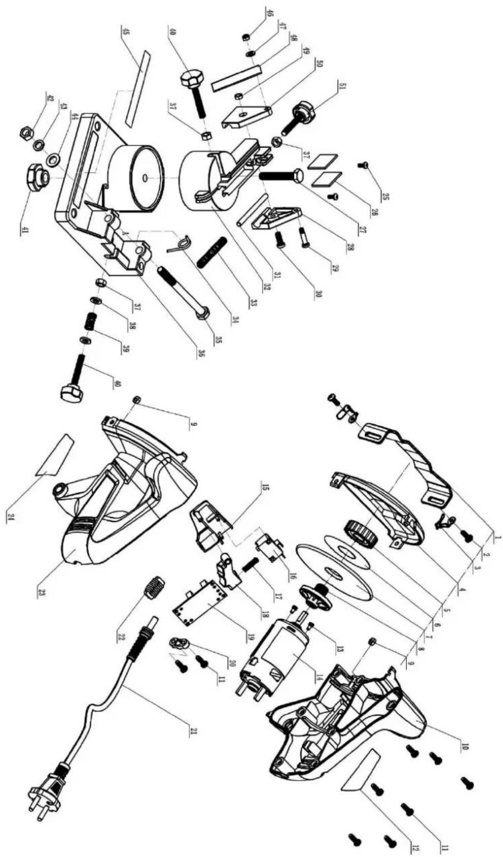
37. Parts List
| Part # | Description | Quantity | Part# | Description | Quantity |
| 1 | Housing fuse | 1 | 27 | Screw | 1 |
| 2 | Screw | 2 | 28 | Left Cover | 1 |
| 3 | Chain | 2 | 29 | Screw | 1 |
| 4 | Grinding wheel cover | 1 | 30 | Screw | 1 |
| 5 | Locking disc | 1 | 31 | Splint | 1 |
| 6 | Grinding Wheels Label | 1 | 32 | Chain guide | 1 |
| 7 | Grinding wheel | 1 | 33 | Spring | 1 |
| 8 | Locking disc | 1 | 34 | Torsion Feeder | 1 |
| 9 | Mother | 2 | 35 | Bolt | 1 |
| 10 | Left Cover | 1 | 36 | Plinth | 1 |
| 11 | Screw | 9 | 37 | Nut | 3 |
| 12 | Label | 1 | 38 | Washer | 2 |
| 13 | Screw | 2 | 39 | Spring | 1 |
| 14 | Engine | 1 | 40 | Screw | 1 |
| 15 | Switch Socket | 1 | 41 | Mother | 1 |
| 16 | Switch | 1 | 42 | Mother | 1 |
| 17 | Spring | 1 | 43 | Spring pad | 1 |
| 18 | Trigger | 1 | 44 | Washer | 1 |
| 19 | Printed circuit board | 1 | 45 | Warning sign | 1 |
| 20 | Press plate | 1 | 46 | Mother | 1 |
| 21 | Cable | 1 | 47 | Washer | 1 |
| 22 | Induction coil | 1 | 48 | Chain stop | 1 |
| 23 | Right Cover | 1 | 49 | Mother | 1 |
| 24 | Nameplate | 1 | 50 | Right Cover | 1 |
| 25 | Screw | 2 | 51 | Screw | 2 |
| 26 | Clamp | 2 |
PLEASE READ THE FOLLOWING TEXT CAREFULLY THE MANUFACTURER OR DISTRIBUTOR HAS PROVIDED THE INSTALLATION DIAGRAMS FOR REFERENCE PURPOSES ONLY FOR THIS MANUAL. NEITHER THE MANUFACTURER NOR THE DISTRIBUTOR MAKES ANY REPRESENTATION OR WARRANTY TO THE BUYER THAT THE BUYER IS QUALIFIED AND AUTHORIZED TO CARRY OUT REPAIRS OR REPLACEMENT OF INDIVIDUAL PARTS OF THE PRODUCT. INSTEAD, THE MANUFACTURER OR DISTRIBUTOR EXPLICITLY STATES THAT ALL REPAIRS AND PARTS EXCHANGES WILL NOT BE CARRIED OUT BY THE BUYER HIMSELF; BUT MAY BE CARRIED OUT BY A LICENSED TECHNICIAN. THE BUYER ASSUMES THE COMPLETE RISK AND FULL LIABILITY FOR HIS OWN REPAIRS OR PARTIAL REPLACEMENTS OF THE ORIGINAL PRODUCT. THE SAME APPLIES TO THE USE OF SPARE PARTS AND ACCESSORIES THAT ARE NOT AUTHORIZED BY THE MANUFACTURER OR DISTRIBUTOR.
Note: Some parts are listed and are for illustrative purposes only, but may not be available as spare parts individually.
- Assembly drawing
text_image
Exploded view diagram of a mechanical assembly with numbered parts for identification39. Disposal

Dispose of the packaging by type. Provide cardboard and carton to waste paper, foils to the recyclable materials collection.
Disposing of old appliances
(Applicable in the European Union and other European countries with systems for the separate collection of recyclables) Old appliances must not be disposed of in household waste!
If the sharpener can no longer be used, every consumer is legally obliged to hand in old appliances separately from household waste, e.g. at a collection point in their municipality/district. This ensures that old equipment is properly recycled
and negative effects on the environment are avoided. That is why electrical appliances are marked with the symbol above.
40. EU declaration of conformity
in accordance with Directive 2006/42/EC
FUXTEC GmbH
Kappstrasse 69, 71083 Herrenberg - Germany
declares in sole responsibility that the product is a saw chain sharpener
Modell 2002E / CX-KSF700
to which this statement relates, the relevant essential safety and health requirements of Directives 2006/42/EC, as well as the requirements of the other relevant Directives
EN 61029-1:2009 + A11:2010
EN 61029-2-10:2010 + A11:2013
EN ISO 12100: 2010
A9-B-88:2014
Intertek Deutschland GmbH Certification Body, ID Number 0905, Stangenstraße 1, 70771 Leinfelden-Echterdingen, Germany
Guaranteed/measured sound power level LwA: 86 dB(A) / LpA: 75 dB(A)
Storage of technical documents:
FUXTEC GmbH ● Kappstraße 69 ● 71083 Herrenberg ● Germany
T. Zelic, Managing Director
VERSION ESPANOLA
natural_image
Mechanical tool with transparent casing and metal base, no visible text or symbolsSu nuevo
natural_image
Mechanical device with a dome-shaped top and mechanical clamp (no visible text or symbols)natural_image
Close-up of a mechanical device with transparent casing and metal hardware (no visible text or symbols)Pedestal (#36)
natural_image
Close-up of a hand operating a mechanical tool with a spring and chain, no visible text or symbolsFigura 8

natural_image
Close-up of a mechanical device with a circular component and attached bracket (no visible text or symbols)natural_image
Close-up of a mechanical assembly with a textured surface and metal clamping (no visible text or symbols)natural_image
Close-up of a mechanical component with a circular component and a lever mechanism (no visible text or symbols)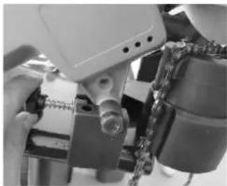
natural_image
Close-up of a robotic arm with chains and mechanical components (no visible text or symbols)Figura 11
text_image
Exploded view diagram of a mechanical assembly with numbered parts for identification49. Disposición

T. Zelic, Director General
VERSAO PORTUGUESA
MANUAL DE INSTRUÇÕES ORIGINAL
natural_image
Close-up of a mechanical tool with transparent grip and metal base (no visible text or symbols)CE
natural_image
Mechanical device with clamping mechanism and mounting bracket (no visible text or symbols)6mm através do

natural_image
Close-up of a mechanical clamp device with a transparent cover and metal screw, labeled Fig. 2 (no text or symbols on the device itself)Pedestal (#36)
natural_image
Close-up of a hand operating a mechanical tool with a metallic bracket and chain link (no visible text or symbols)natural_image
Close-up of a mechanical device with a circular component and attached lever mechanism (no visible text or symbols)natural_image
Close-up of a mechanical assembly with a textured surface and metal clamps (no visible text or symbols)natural_image
Close-up of a mechanical device with a coiled component and a tool, no visible text or symbolsFig. 11
natural_image
Close-up of a robotic arm with chains and mechanical components (no visible text or symbols)text_image
Exploded view diagram of a mechanical device with numbered parts for identification59. Eliminação

natural_image
Mechanical tool with transparent head and metal base, no visible text or symbolsCE
natural_image
Mechanical device labeled 'Figuur 1' showing a dome-shaped component mounted on a wall with a mechanical lever (no visible text or symbols)6 mm doorgaand gat
natural_image
Close-up of a mechanical device with transparent casing and metal hardware (no visible text or symbols)Sokkel (#36)
natural_image
Close-up of a hand operating a mechanical tool with a spring and chain (no visible text or symbols)Figuur 8
natural_image
Close-up of a mechanical device with a circular component and attached bracket (no visible text or symbols)natural_image
Close-up of a mechanical assembly with a textured fabric and metal clamping tool (no visible text or symbols)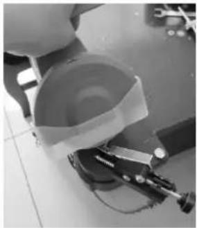
natural_image
Close-up of a mechanical device with a paper roll and clamping tool on tiled floor (no visible text or symbols)natural_image
Close-up of a robotic arm with chains and mechanical components (no visible text or symbols)Figuur 11
text_image
Exploded view diagram of a mechanical assembly with numbered parts for identification69. Zin

natural_image
Close-up of a mechanical tool with transparent casing and metal base (no visible text or symbols)CE
natural_image
Mechanical device with transparent housing and metal clamps, labeled 'Piedestal (#36)' (no readable text or symbols on the device itself)natural_image
Close-up of hands operating a mechanical tool with a bolt and spring (no visible text or symbols)natural_image
Close-up of a mechanical assembly with a circular component and attached bracket (no visible text or symbols)natural_image
Close-up of a mechanical assembly with a textured fabric and metal clamped components (no visible text or symbols)natural_image
Close-up of a mechanical device with a rolled paper or tape and a clamping tool on a tiled floor (no visible text or symbols)Fikon. 11
natural_image
Close-up of a robotic arm with chains and mechanical components (no visible text or symbols)text_image
Exploded view diagram of a mechanical assembly with numbered parts for identification79. Förfogande

POLSKA WERSJA JEZYKOWA
ORYGINALNA INSTRUKCJA OBSŁUGI
natural_image
Mechanical robotic arm with transparent head and metal base, no visible text or symbolsCE
natural_image
Mechanical device with a circular component mounted on a stand, labeled 'Rys. 1' (no other text or symbols visible)Otwór przelotowy 6
natural_image
Close-up of a mechanical device with a transparent dome and metal clamp, labeled 'Rys. 2' in the top-left corner (no other text or symbols visible)Postument (#36)
natural_image
Close-up of a mechanical assembly with chains and a central component (no visible text or symbols)natural_image
Close-up of a mechanical device with a circular component and attached lever mechanism (no visible text or symbols)natural_image
Close-up of a mechanical assembly with a textured fabric and metal clamping tool (no visible text or symbols)natural_image
Close-up of a mechanical device with a circular component and clamping tool (no visible text or symbols)
natural_image
Close-up of a robotic arm with chains and mechanical components (no visible text or symbols)Rys. 11
text_image
Exploded view diagram of a mechanical device with numbered parts for identification89. Dyspozycji