FX-FSR162 - Lawn mower Fuxtec - Free user manual and instructions
Find the device manual for free FX-FSR162 Fuxtec in PDF.
User questions about FX-FSR162 Fuxtec
0 question about this device. Answer the ones you know or ask your own.
Ask a new question about this device
Download the instructions for your Lawn mower in PDF format for free! Find your manual FX-FSR162 - Fuxtec and take your electronic device back in hand. On this page are published all the documents necessary for the use of your device. FX-FSR162 by Fuxtec.
USER MANUAL FX-FSR162 Fuxtec
natural_image
Line drawing of a mechanical device with articulated arms and wheels, no text or symbols present
natural_image
Orange icon of a person reading a book (no text or symbols)
natural_image
Icon of a hand pointing at an open book with horizontal lines representing text (no actual text or symbols)Inhalt
DEUTSCHE VERSION....11
ENGLISH VERSION....36
VERSION FRANCAISE....61
POLSKA WERSJA JEZYKOWA 215
Inhalt
DEUTSCHE VERSION....11
-
Technical data....37
-
Symbols and safety instructions on the device 38
-
Intended use and general safety instructions 41
-
Notes for accessories....43
-
Symbols on the device 44
-
Component overview....45
-
Assembly of the device....46
-
Fuels....48
-
Cold start of the device....51
-
Warm start of the device....52
-
Stopping the device....52
-
Trimming techniques....52
-
Replacing the nylon thread....54
-
Maintenance plan....55
-
Storage of the device....57
-
Troubleshooting ....58
-
Customer Service....59
-
Warranty....59
-
Disposal note 59
-
EU Declaration of Conformity....60
VERSION FRANCAISE....61
POLSKA WERSJA JEZYKOWA 215
natural_image
Technical line drawing of a mechanical measuring tool with attached sensors and wheels (no text or symbols)Position: Tankdeckel

text_image
Technical diagram of a mechanical device with numbered components for identificationnatural_image
Technical line drawing of a mechanical assembly with no visible text or symbols
text_image
Technical diagram of a mechanical device with labeled parts, showing internal components and assembly steps.
natural_image
Technical line drawing of a mechanical device with no visible text or symbols
text_image
4 ① ② ② ①text_image
Technical diagram of a mechanical assembly with numbered parts for identificationnatural_image
Diagram showing a mechanical component with a red arrow indicating direction, no text or symbols present■ Höhenverstellung
HINWEIS
text_image
Technical diagram of a mechanical device with labeled parts A, B, and C, showing assembly or maintenance instructions.
natural_image
Red and black plastic tool with threaded end, next to a metallic mesh nut (no text or symbols visible)
natural_image
Close-up of a hand adjusting a red plastic clip attached to a black metal bracket (no text or symbols visible)
natural_image
Close-up of hands adjusting a black tool with an orange plastic clip (no text or symbols visible)
natural_image
Close-up of a mechanical clamp with an orange handle and black rod (no text or symbols visible)natural_image
Close-up of a mechanical component with orange plastic parts and a red arrow indicating a specific part (no visible text or symbols)
natural_image
Close-up of an orange automotive component with a black plastic container and red arrow indicating a specific part (no text or symbols visible)natural_image
Close-up of a black and orange electric fan device with a hand adjusting its top panel, showing a red arrow pointing to the component (no text or symbols visible)5

natural_image
Close-up of a hand inserting a small component into a black industrial machine with orange clamps (no visible text or symbols)natural_image
Diagram of a mechanical device emitting particles with directional arrows indicating flow or movement (no text or symbols)DER NYLONFADEN

natural_image
Diagram of a naval gun firing from a ship deck, showing blade and gear components (no text or symbols)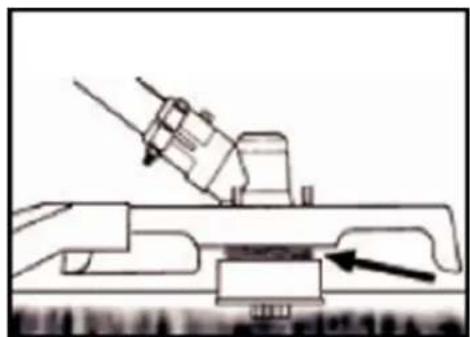
natural_image
Technical line drawing of a mechanical assembly with an arrow indicating a component (no text or symbols present)natural_image
Technical line drawing of a mechanical component with directional arrows indicating flow or movement (no text or symbols)natural_image
Close-up of a hand adjusting a black and orange electronic device component (no visible text or symbols)
natural_image
Close-up of a mechanical device with orange handle and black housing, showing internal components (no text or symbols visible)Wartung Zündkerze
text_image
0.6~0.7 mmnatural_image
Close-up of a mechanical component with labeled parts F and E, showing internal components and a ruler-like structure (no readable text or symbols beyond labels)Benzinfilter
natural_image
Line drawing of a hand holding a tool near a device (no text or symbols)Wheeled petrol brush cutter
FX-FSR162

natural_image
Technical line drawing of a mechanical device with articulated arms and wheels (no text or symbols)Your new device has been developed and designed to meet FUXTEC's high standards, such as easy operation and user safety. Properly treated, this device will serve you well for years to come.

WARNING: To reduce the risk of injury, the user must read and understand this manual before operating the device.
FUXTEC GMBH, KAPPSTRAße 69, 71083 HERRENBERG, GERMANY
We are continually striving to improve our products. Therefore technical data and illustrations can change!
- Technical data
| Typ | FX-FSR162 |
| Engine | Air-cooled; 2-stroke |
| Cubic capacity | 62cm^3 |
| Maximum output power (kW)(in accordance with ISO 8893) | 2.6kW / 7,500min^-1 |
| Maximum speed of the engine | 9,000 min^-1 |
| Idle speed of the device | 3,000 min^-1 |
| LPA at the operator station | 88 dB(A) (K=3dB) |
| Measured L_WA according to ISO 10884 | 108.8 dB(A) (K=3dB) |
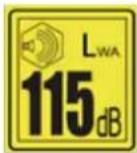
| Guaranteed L_WA | 115 dB(A) |
| Maximum vibration values at each handle | 6.822m/s^2 k=1.5m/s^2 |
| Thread-diameter | Φ3mm |
| Rotation direction of the cutting device | counterclockwise |
| Number of the handle | 2 |
| Dry weight (without fuel, cutting set, carrying strap) | 13.62 kg |
| Fuel tank capacity (L) | 0.85 |
| Fuel consumption (kg/h) (in accordance with ISO 8893) | 0.89 |
| Specific fuel consumption (g/kWh) (in accordance with ISO 8893) | 630 |
| Carburettor | Diaphragm |
| Ignition | CDI |
| Engine type | TT1E47.5F |
22. Symbols and safety instructions on the device
 | WARNUNG! IMPROPER USE CANCAUSE SERIOUS INJURY |
 | READ AND UNDERSTAND THIS USER MANUAL BEFORE USE. |
 | ALWAYS WEAR EYE PROTECTION, EAR PROTECTION AND HEAD PROTECTION |
 | WEAR FOOT PROTECTION. |
 | WEAR GLOVES (SHARP EDGE!). |
 | DO NOT TOUCH THE ROTATING BLADE,DANGER OF INJURY |
 | ALWAYS KEEP 15 METERS FROM OTHERPEOPLE |
 | THE GUARANTEED NOISE LEVEL CORRESPONDS TO THE LEGALNOISE GUIDELINES |
 | WARNING OF FLYING OBJECTS |
 | NO SMOKING AND OPEN FLAMES ON THE DEVICE |
 | WARNING: DANGER OF HOT COMPONENTS |
 | ALWAYS TURN OFF THE DEVICE AND MAKE SURE THE CUTTING TOOL IS STOPPED BEFORE CLEANING, REMOVING OR ADJUSTING IT. |
 | WARNING: FUMES FROM THIS PRODUCT CONTAIN CHEMICALS THAT CAUSE CANCER, BIRTH DEFECTS AND FURTHER CAN LEAD |
 | WARNING! NEVER MODIFY THE DEVICE. IMPROPER USE OF THE DEVICE CAN CAUSE SERIOUS OR FATAL PERSONAL INJURY. |
 | WARNING! FLAMMABLE MATERIALS |
 | MAXIMUM SPEED OF THE SPINDLE (TURN TRIMMER): 6600 min-1 |
 | MOUNT THE CONNECTING TUBE TO THE ENGINE AS SHOWN IN THIS FIGURE |
 | NO CUTTING BLADES MAY BE USED WITH THIS DEVICE |
IMPORTANT
In the case of loosening of the safety instruction stickers, they should be replaced immediately.
Do not let others use this device unless these persons have been fully instructed, have read and understood the device manual and have been trained in the operation of the device.

More extended use of the device exposes the user to vibrations, which can lead to white finger disease (Raynaud's syndrome) or carpal tunnel syndrome. This condition reduces the hand's ability to feel and regulate temperatures, causes numbness and
heat sensations and can lead to nerve and circulatory damage and tissue death.
Not all factors leading to white finger disease are known. Still, cold weather, smoking and other diseases affecting the blood vessels and blood circulation, as well as extensive or prolonged exposure to shocks are mentioned as factors in the development of white finger disease. To reduce the risk of white finger disease and carpal tunnel syndrome, please note the following
- Wear gloves and keep your hands warm
• Take regular breaks
All the above precautions cannot exclude the risk of white finger disease or carpal tunnel syndrome. Long-term and regular users are, therefore recommended to monitor the condition of their hands and fingers closely. Consult a doctor immediately if any of the above symptoms occur.

The operating noise of the tool may damage your hearing. Wear a sound-proofing (Oropax or ear muffs) to protect it. Long-term and regular users are recommended to check your hearing regularly. Be especially vigilant and careful when wearing hearing protection as it limits your
ability to hear warnings (cries, alarms, etc.).

WARNING: Some noise exposure from this device cannot be avoided. Do not work in noisy environments during approved and designated times. If necessary, observe rest periods and limit the working time to the absolute minimum. For your protection and protection of persons in the vicinity, wear suitable hearing protection.
23. Intended use and general safety instructions
This device may only be used for mowing or trimming grass, weeds and undergrowth. Never use it for other purposes, as this may cause serious injuries!
Correct safety instructions must be observed. DO NOT EXPOSE YOURSELF OR OTHERS TO DANGER. Follow these general safety instructions:
- Always wear safety glasses for eye protection. Long hair must be tied back. Do not wear loose clothing or jewellery that can get caught in moving parts of the device. Safe, robust, non-slip safety shoes must always be worn. It is recommended that legs and feet are fully protected to guard against flying objects during operation
- Check the entire device for loose parts (nuts, bolts, screws, etc.). Maintain or replace them, if necessary, before using the device. Do not use accessories with this drive head other than those recommended by the manufacturer. Otherwise, severe injury to the user or bystanders and damage to the device may result
- Keep the handles free of oil and fuel
• Always use correctly mounted handles when cutting - Do not smoke when mixing the fuel or filling the tank
- Do not mix fuel in an enclosed space or near open fires. Ensure adequate ventilation / aeration
- Mix and store the fuel mixture in a marked container approved for such use according to local regulations
- Never remove the fuel tank cap while the device is running
- Do not operate the device in closed rooms or buildings. Exhaust gases contain dangerous carbon monoxide
- Do not use the device if it is damaged. Never remove safety equipment from the device. Otherwise, the operator or the spectators may be seriously injured, and the device may be damaged
- Check the area to be cut and remove any residue that may be entangled in the nylon cutting head. Also, remove any objects that the device may throw around during cutting
• Never leave the device unattended - Do not stretch out far forward. Always maintain a secure stand and balance.
- Children must not have access to the device. Spectators should stand at least 15 meters away from the working area.
- Keep hands and feet away from the nylon cutting head during operation
- Do not use the device if you are tired, sick or under the influence of medication, drugs or alcohol
-
Use an entire nylon cutting head. If you hit a stone or any other obstacle, stop the device and check the nylon cutting head. A defective or unbalanced nylon cutting head must never be used
-
Before starting, after failure or impact, make sure to check the device and make sure that it is in good condition
- Caution! Local regulations may limit the use of the device
- Always keep the device with the cutting tool in good condition. Please note that improper maintenance, the use of non-compliant spare parts or the removal or modification of safety devices can cause damage to the device and severe injury to the person working with it
- Secure the device properly during transport to prevent loss of fuel, damage to the device and injury.
- For devices with a clutch, regularly check that the cutting attachment stops rotating when the engine is idling
- Check the device before each use for loose fasteners, fuel leaks, damaged parts, etc. Replace damaged parts before use
• It is necessary to take sufficient breaks - Do not store the device in an enclosed area where fuel vapours can reach an open fire from water heaters, stoves, etc. Store the device in a well-ventilated area only.
- IMPORTANT: When filling fuel, make sure that the device is off and cooled down. Never refuel when the device is running or hot. If gasoline is spilt, wipe it up before starting the device
24. Notes for accessories
- Make sure that your product is only equipped with original accessories. Only use original parts that are specified by the manufacturer. The use of any other accessories or attachments may cause injury to the user and damage to the device
- Clean the device thoroughly, mostly the fuel tank and air filter. After using the device, remove all fuel
- If you, as a bystander, approach a user of the device, carefully attract his attention and confirm that the user will stop the engine. Please do not startle or distract the user; otherwise, you could cause an unsafe situation
- Never touch the nylon cutting head when the device is running. If it is necessary to replace the guard or cutting tool, be sure that the device and cutting tools have stopped
- The device must be OFF before you change the working range of the device
- If necessary, have the device repaired by an authorized dealer. If the device is defective, do not let it continue to run
- When starting or operating the device, never touch hot parts such as the exhaust, the ignition cables or the spark plug
- After the device is stopped, the exhaust is still hot. Never place the device near inflammable materials (dry grass, inflammable gases or inflammable liquids, etc.)
- Pay particular attention to the fact that the ground can be slippery when operating in the rain or immediately after the rain
- If you glide or fall to the ground, release the throttle immediately
- Before removing the blockage, stop the device and remove the spark plug connector. Before adjusting or repairing the device, make sure that the engine is stopped, and the spark plug connector is removed.
• Make sure that you do not hit the device against obstacles - If the device is to be stored for a more extended period, drain fuel from the fuel tank and carburettor, clean the parts, place the device in a safe place and make sure that the device has cooled down completely
- Carry out constant checks to ensure safe and efficient operation of the device. For a complete inspection, please contact a specialist workshop
- Keep the device away from fire or sparks
- Be careful when using it. There are dangers due to kickback and recoil
25. Symbols on the device
WARNING
◆ For safe operation and maintenance, symbols are attached to the device. Adhere to the instructions to avoid errors

The filler neck "Gasoline/2-cycle oil mixture 1/40
Position: Fuel filler cap

Set the switch to "|" position, the engine starts.
Set the switch to "O" position, stops the motor.
Position: right handle (on the left side)

Choke lever in this position closes the carburettor
Position: Air filter cover

Choke lever in this position means the carburettor is open
Position: Air filter cover
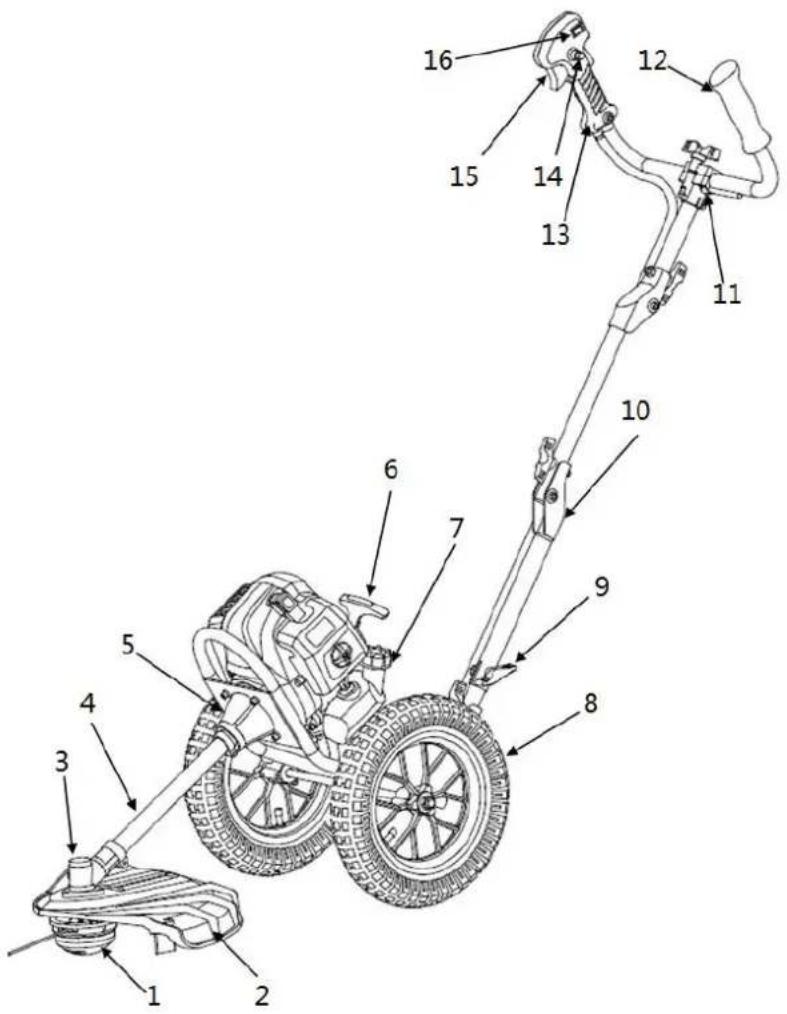
26. Component overview
1) Nylon thread head
2) Protective shield
3) Gearbox
4) Drive axle
5) Clutch bell
6) Starter hoist
7) Tank
8) Wheel
9) Connector
10) Rotary connectors
11) Handle connector
12) Left-hand handle
13) Right-hand handle
14) Throttle lever lock*
15) Throttle lever
16) Start/stop switch
text_image
Technical diagram of a mechanical device with numbered parts for identification*14 Throttle lock prevents accidental
acceleration of the engine. The throttle
stick can only be pressed when the throttle stick lock is pressed
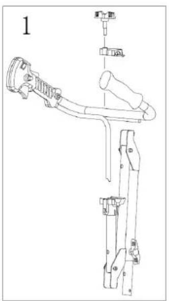
27. Assembly of the device
■ Assembly of the frame
natural_image
Technical line drawing of a mechanical assembly with no visible text or symbols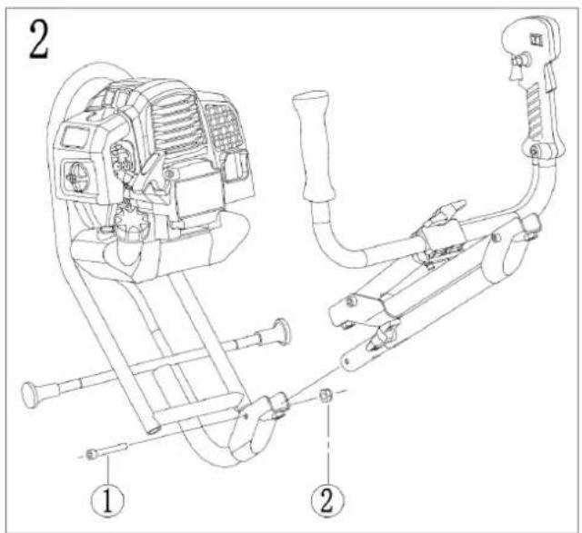
text_image
2 ① ②
natural_image
Technical line drawing of a mechanical device with no visible text or symbols
text_image
4 ① ② ② ①- Put the handle into the intended holder and fix it with the shown clamp and the corresponding wing screw.
- Fasten the handle with the appropriate screw (1) and nut (2)
- Remove the covers
- Mount the wheels on both sides by attaching the illustrated parts in the following order: Tire (2) - nut (1). Then tighten the nut (1).
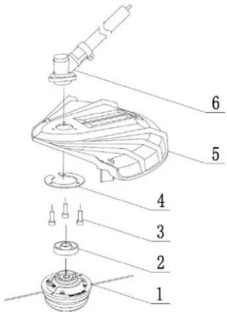
■ Mounting the protective shield
Attach the protective shield (5) and gear unit cover (4) with the gear unit (6) using the screws (3) supplied and tighten these screws.
■ Assembly thread head
Place the holder (2) on the shaft under the protective shield (5)
Use the tool provided to lock the gear assembly and tighten the thread head by hand (Note: left-hand thread)
text_image
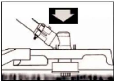
Technical diagram of a mechanical assembly with numbered parts for identification■ Mounting driveshaft
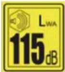
Push the shaft into the clutch bell. Make sure that the hole on the shaft is on the screw side of the
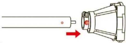
natural_image
Diagram showing a mechanical component with a red arrow indicating direction, no text or symbols presenthousing and tighten the screw.
■ Height adjustment
NOTE
This device has the possibility of height adjustment to be adapted to different users and thus ensure better working conditions.
Use the screws of holes A, B, C on the lower tube and adjust the device to your height by tightening
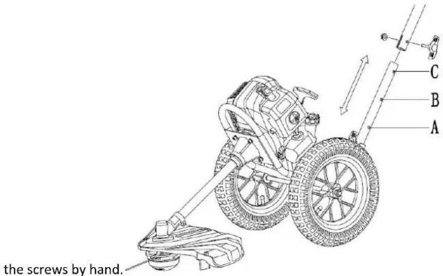
text_image
the screws by hand. A B C
natural_image
Red plastic tool with threaded screw and metallic nut on white background (no text or symbols)
natural_image
Close-up of a hand adjusting an orange plastic clip on a black metal bracket (no text or symbols visible)
natural_image
Close-up of hands adjusting a mechanical component with orange plastic clips (no text or symbols visible)
natural_image
Close-up of a black pipe fitting with an orange plastic clamp, no visible text or symbols- Use the butterfly screw and the non-slip nut to connect individual elements.
- Insert the butterfly screw through the guide hole provided in the pole as shown. The end of the butterfly screw fits into the curved surface of the rod.
- Screw the nut onto the bolt first and then adjust the iron piece level.
- then turn the wing screw by hand to the right until the plane of the screw matches the iron surface and tighten it without loosening it.
- Make sure that the plane of the wing screw is tight against the iron surface and is not loose. Follow installation steps 1-4 and install the other 2 places in order.
28. Fuels
FUEL AND 2-STROKE OIL
Use unleaded gasoline with 2-stroke engine oil in a 40:1 ratio. During the first few operations, a mixing ratio of 25:1 can be selected in order to lubricate all device parts optimally initially.

WARNING: Never use pure gasoline in your device. This will cause permanent engine damage and voids the manufacturer's warranty for this product. Never use a fuel mixture that has been stored for more than 90 days.

WARNING: It must be a first-class oil for 2-stroke air-cooled devices.
We recommend the FUXTEC two-stroke oil "MADE IN GERMANY".

text_image
FOXTEC SUPER 2T 200 LTR/FTM REBEING FIELD STAFFER STRIKE 10L SALO FULL SWEET FULL SWEET FULL SWEETFUEL MIXTURE
Mix fuel with 2-stroke oil in a particular container. Please note the mixture table on the following page for the correct ratio of gasoline to oil. Shake the tank to ensure complete mixing.
| Gasoline | Two-stroke engine oil(40:1) | Gasoline | Two-stroke engine oil(40:1) |
| 1 liter | 0.025 liter | 5 liter | 0.125 liter |
| 2 liter | 0.050 liter | 10 liter | 0.250 liter |

WARNING: Lack of lubrication excludes the liability of the device manufacturer. Gasoline and oil must be mixed in a 40:1 ratio.
Recommended fuel
It is recommended to use unleaded gasoline with an octane number of 90 # or higher to reduce carbon deposition in the combustion chamber. Do not use old or dirty gasoline. Keep the fuel tank dust-free and avoid water getting into the tank. Sometimes overload will cause misfiring, which is normal.
If the backfiring is heard under average load, we recommend replacing the gasoline. If the misfire is still present afterwards, please contact an authorized workshop.

WARNING
● Gasoline is highly flammable and can cause an explosion in case of sparks
● Refuel only in well-ventilated rooms and let the engine cool down before filling. Smoking and open fire, as well as any sparks, must be avoided during refuelling
- Do not overfill the tank (see figure max. filling level)
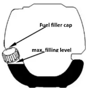
text_image
Fuel filler cap max. filling level● After refuelling, check that the fuel filler cap is properly closed
● Avoid any spillage of gasoline
- Keep the device away from children
Gasoline with an ethanol content
The engine can be operated with E10 gasoline.
However, do not use gasoline with
a higher ethanol content than 10%.
29. Cold start of the device
WARNING
The cutting head rotates immediately when the engine is started.
1) Ensure a secure stand and a firm and level surface.
Slide the engine stop switch on the right handle to the position I
Push the switch to position 0 you have no ignition spark and the engine cannot be started
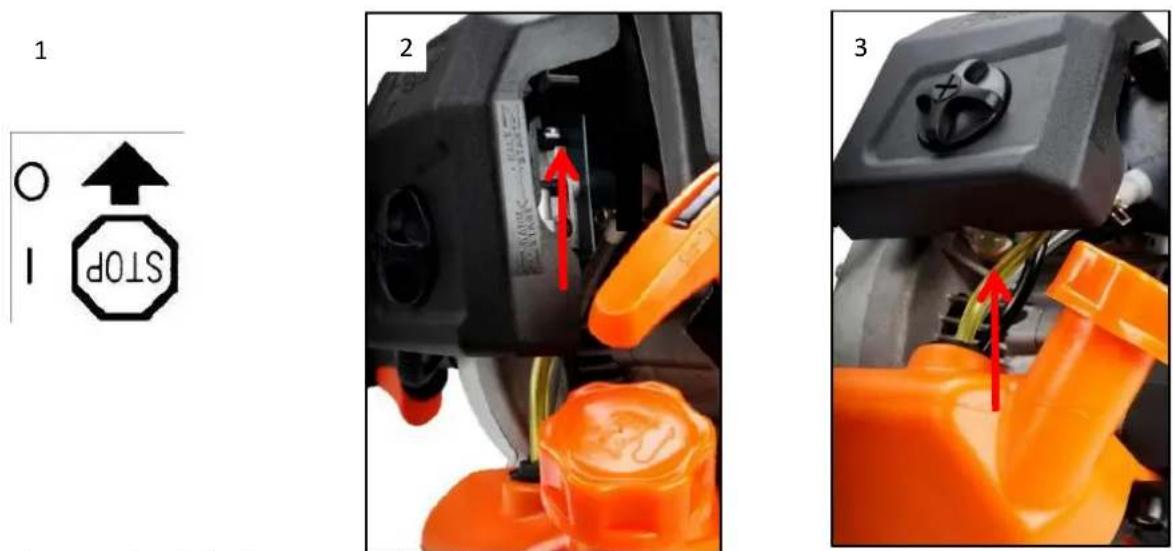
2) Move the choke lever upwards to "COLD START".
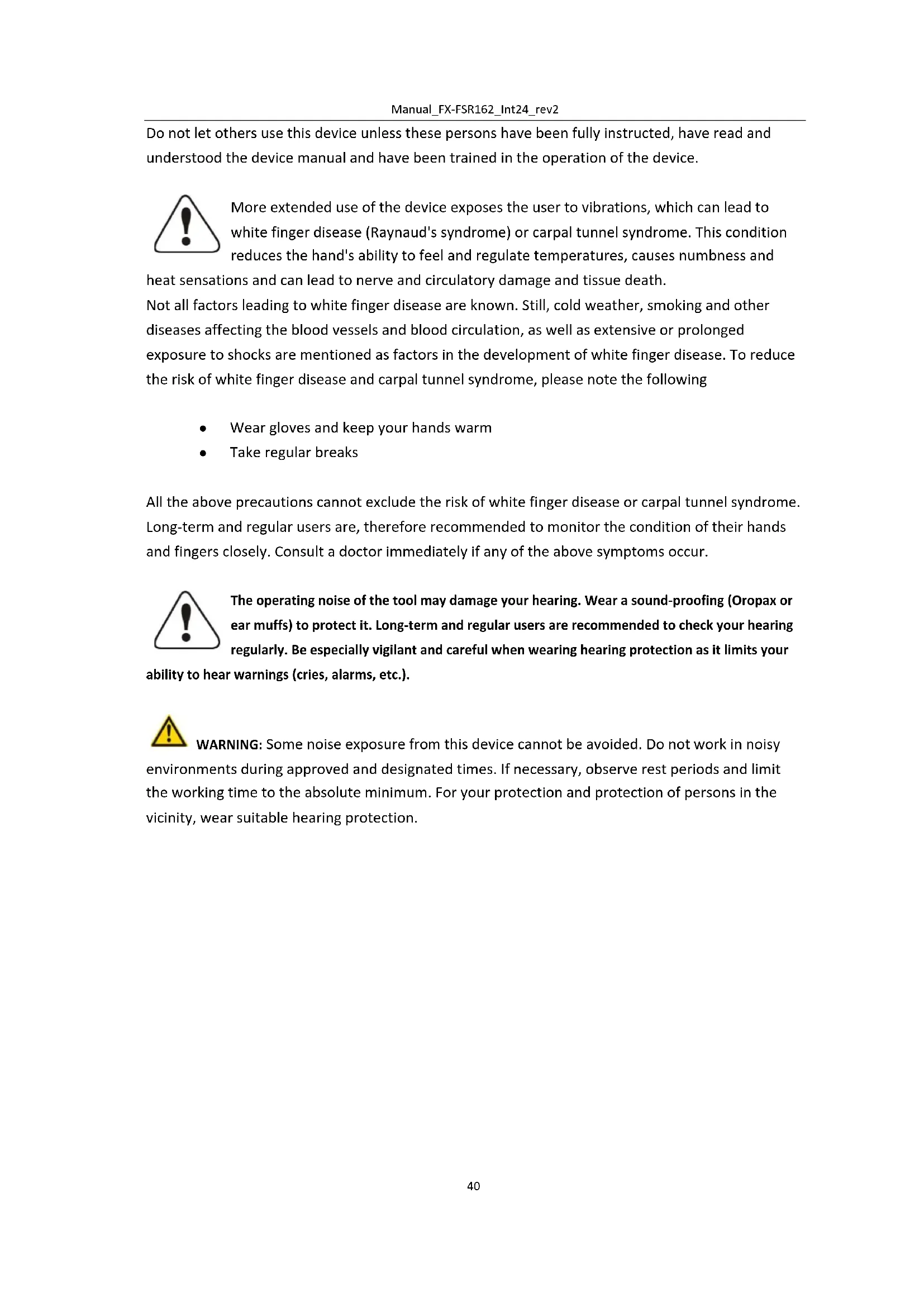
3) Press the carburettor pump about 8-10 times (until gasoline flows in the line)
4) Pull out the starter rope with a short-stroke until resistance is felt
(about 100mm). A continuous fast train will provide a vital spark and start the engine

natural_image
Close-up of a black and orange electric shock absorber device with a hand adjusting its top panel (no visible text or symbols)5

natural_image
Close-up of a hand adjusting a black industrial machine with orange tool (no visible text or symbols)5) Then set the choke lever to the "WARM START" position
6) Let the engine warm-up for a few minutes at idle
NOTE: If the device does not start after repeated attempts, refer to troubleshooting chapters.
NOTE: Always pull the starter cord straight out. Pulling the starter at an angle will cause the rope to rub against the eyelet. Pulling the starter at an angle can cause the starter cord to fray or break. Always hold the starter handle firmly when the rope pulls back. Never let the hoist be thrown back from the pulled-out position. This could damage the starter unit.
30. Warm start of the device
1) Place the device on a firm and level surface.
2) Move the engine stop switch to position I
3) Slide the choke to the "WARM START" position
4) Pull out the starter rope with a short-stroke until resistance is felt
(about 100mm). A continuous fast train will provide a vital spark and start the engine
If the device does not start, please proceed again according to "Cold start of the device
31. Stopping the device
Unlock the throttle lever. Let the device return to idle. Push the engine stop switch on the handle upwards until the device stops. If it does not stop, pull out the spark plug connector in an emergency. Never leave the device unattended while it is running.
32. Trimming techniques
ADDITIONAL SAFETY INSTRUCTIONS
Before running your device, read the notes in chapters 3 and 4 of this manual.
CAUTION
ALWAYS TRIM AT HIGH ENGINE SPEEDS. Do not let the device run slowly at the beginning or in trim mode.
ALWAYS MAKE DISTANCE IN WORKING AREAS from cans, bottles, rocks, etc. Whirling objects can cause serious injury to users or bystanders and damage the device. If an object is accidentally knocked against, immediately turn OFF the DEVICE and check the device. Never run the device with damaged or defective parts.
DO NOT use the device for any purpose other than trimming grass.
Never lift the nylon cutting head above knee height during operation.
Do not run the device on a slope if there is a chance of slipping or losing stability.
Always remember that the tip of the thread will cut. You will get better results if you do not push
into the cutting area. Let the device trim at its own pace
Hold the device in such a way that the thread head does not touch the ground and is inclined slightly 20 degrees to the swing direction.
You can make your work easier by trimming from right to left

natural_image
Diagram of a wind turbine blade with airflow and particle motion arrows (no text or symbols)THE NYLON THREAD

CAUTION: Remove grass deposits regularly to prevent overheating of the drive axle. Grass deposits occur when fibres of the weed become entangled around the shaft under the protective shield. That prevents the shaft from cooling properly. Remove grass deposits with a screwdriver or similar tool only when the device is switched off.
natural_image
Technical line drawing of a naval gun on a ship deck with a downward arrow indicating force or impact (no text or symbols present)
natural_image
Technical line drawing of a mechanical assembly with an arrow indicating a component (no text or symbols present)If the device is properly equipped with a protective shield and nylon cutting head, your device will trim unsightly weeds and large diameter tall grass in areas along fences, walls, land and around trees.
NOTE: Pay special attention when trimming on brick or stone walls, etc., which will cause rapid weed wear.
TRIMMING MORE ACCURATELY
Swing the trimmer's nylon cutting head horizontally from side to side. Do not tilt the nylon cutting head while working. For correct cutting height, trim in advance in a test area. Keep nylon cutting head at the same level for even depth of cut.
TRIMMING AROUND TREES
Trim around logs with a slow approach; the thread should not collide with the log. Walk around the tree from left to right. Approach grass or weeds with the tip of the thread.
33. Replacing the nylon thread
1) Switch off the engine
2) Place the trimmer on the ground so that the drive axle with the coil is exposed and remove the nylon head
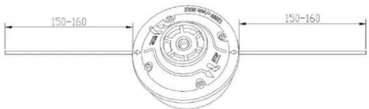
3) Take a 3mm thread and a length of 285mm. Please do not use a longer thread, as this may affect the cutting performance.
4) Push the thread with force into the hole of the thread spool until it comes out at the other side

natural_image
Technical line drawing of a mechanical component with directional arrows indicating flow or movement (no text or symbols)5) Let the thread protrude approx. 150-160mm at both ends
text_image
150-160 150-1606) If the thread is too short, simply pull it out with force and fill the thread head with a longer thread

text_image
Technical diagram of a mechanical component with labeled parts and directional arrows indicating motion or assembly.34. Maintenance plan
Regular checks and adjustments must be made to ensure that the gasoline engine maintains its performance. Regular maintenance also ensures a long service life. See the following table for the regular maintenance period.
| Maintenance cycleComponent | Every use | Every month or 10h | Every 3 months or 25h | Every 6 months or 50h | Every 12 months or 100h | Every 2 years or 300h | |
| Air Filter | Check | ■ | |||||
| Clean up | ■a | ||||||
| Spark plug | Check & adjust | ■ | |||||
| Exchange | ■ | ||||||
| Spark plug connector (optional) | Clean up | ■ | |||||
| Cooling fins | Exam | ■ | |||||
| Connecting elements such as screws and nuts | Check (tighten if necessary) | ■ | |||||
| Coupling | Exam | ■b | |||||
| Idle speed | Check and adjust | ■b | |||||
| Valve clearance | Check and adjust | ■b | |||||
| Combustion chamber | Clean up | 300h thereafter | |||||
| Fuel | Check | ■ | |||||
| Fuel tank | Check | ■ | |||||
| Fuel line | Check | Every x years (replace if necessary) | |||||
WARNING

a. Increase maintenance intervals if working in dusty environments.
b. All maintenance work - with the exception of that listed in the operating manual must be carried out by qualified maintenance personnel
Cleaning the air filter
CAUTION: Never run the engine without the air filter.
A dirty air filter puts pressure on engine performance, increases fuel consumption and makes starting more difficult. If you notice a loss of engine power:
- Remove the screw on the filter cover and remove the filter.
- Clean the filter with soap and water. Never use gasoline or benzene!
- Let the filter dry in the air.
- Put the filter back in place - fasten the filter cover with the screw.

natural_image
Close-up of a hand adjusting a black and orange electronic device component (no visible text or symbols)
natural_image
Close-up of a black and orange industrial device with internal components, showing no visible text or symbols.Spark plug maintenance
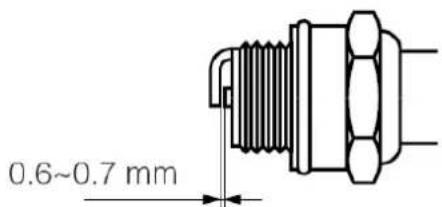
To ensure an optimal operation of the engine, the ignition distance of 0.6-0.7mm must be maintained and must be free of carbon deposits. Always carry out the following steps with the engine switched off:
text_image
0.6~0.7 mm1) Carefully remove the spark plug connector. Do not pull at the cable but directly at the connector (turn slightly left and right to facilitate removal)
2) Use the spark plug wrench supplied to unscrew the spark plug
3) Visually check the spark plug for damage and electrode burn-off,
Remove the carbon deposits
4) Check the gap with a feeler gauge and bend the electrode to the correct distance of 0.6 to 0.7mm
5) Check the spark plug washer and tighten the spark plug with a torque of 9.8-11.8 Nm
6) Mount the ignition cap back on the spark plug
WARNING
The spark plug must be screwed down tightly; otherwise, the engine runs hot and is damaged.
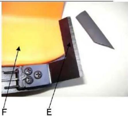
Sharpen the shielded knife
1) Remove cutting knife (E) from protective shield (F).

- Clamp the knife in a vice. Sharpen the knife with a flat-file. Please make sure that you keep the angle of the cutting edge. Only move the sharpening knife in
one direction during the sharpening process.
Fuel filter
In case the tank runs empty, check the fuel filter for clogging The easiest way to remove the fuel filter, including the hose from the inside of the tank and replace or clean it if necessary is to use an Allen key.
natural_image
Close-up of a mechanical component with labeled parts F and E, showing internal components and a ruler-like part (no readable text or symbols beyond labels)
natural_image
Close-up of an orange electrical switch with visible wiring and components (no text or symbols)35. Storage of the device

WARNING: Failure to follow these steps may result in carburettor fouling. That makes later starting difficult and causes permanent damage
1) Perform all general maintenance as described in the maintenance section of your user manual.
2) Clean the exterior of the device, drive axle, protective shield and nylon cutting head.
3) Drain fuel from the fuel tank.
4) After fuel is drained, start the device.
5) Let the device idle until the device stops by itself. That will clean the carburettor of fuel.
6) Let the device cool down (about 5 minutes).
7) Use a spark plug wrench, remove the spark plug.
8) Pour one teaspoon of clean 2-stroke oil into the combustion chamber. Pull the starter rope slowly several times to coat internal components. Replace the spark plug.
9) Store the device in a cool, dry place away from any ignition source such as an oil burner, water heater, etc.
TRANSPORT PROTECTION
Make sure that the device is well-secured during transport to avoid fuel loss, damage or injury.
36. Troubleshooting
1) Difficulties during commissioning
| Situation | Cause | Solution | |
| No ignition spark | Spark plug | Carbon deposit between the diodes of the spark plug | Clean the spark plug. Adjust the gap 0.6~0.7mm, replace the spark plug |
| Other | Ignition coil defective flywheel magnet too weak | Replace the ignition coil or flywheel | |
| Weak ignition spark | Compression | Too much gasoline in the combustion chamber, lousy fuel or water in the tank | Remove the spark plug and allow to dry, replace fuel. |
| Carburettor does not pump oil anymore. | Oil line blocked | Cleaning the carburettor and cleaning the pipes | |
| Regular oil supply but weak compression | Piston rings worn, spark plug not screwed down, cylinder head not tight wrong valve clearance or ignition timing. | Replace screw tight replace or adjust | |
| Regular oil supply and good ignition spark | Poor contact between ignition cap and spark plug | Replace or check | |
2) Difficulties during operation
| Situation | Cause | Solution |
| The engine does not reach a speed | Choke is in "COLD START" position, the exhaust system is blocked no air supply, moving elements worn, ignition spark weak too large valve clearance, cylinder head sooty | Open choke, replace exhaust system Check or replace ignition coil, adjust flywheel, spark plug |
| Operating materials are leaking | Lines to carburettor blocked Spark plug spacing incorrect | Replace lines and carburettor Adjust gap dimension |
| Engine Noises | Wrong choke position, Camshaft damaged | Check/replace camshaft |
| Carburettor leaking | Failure of the check valve on the tank cap | Replace the fuel filler cap |
| Carburettor gasket is worn out | Replace carburettor or gasket |

If no troubleshooting solves the problem, contact your dealer or the manufacturer directly. Only use original parts approved by the manufacturer; otherwise, there is a risk of danger.
37. Customer Service
Have your purchased device repaired only by qualified personnel and only with original spare parts. That ensures that the safety of the device is maintained.
Please contact the manufacturer FUXTEC GmbH directly at info@fuxtec.co.uk at any time regarding maintenance work and procurement of spare parts.
38. Warranty
The warranty period is 24 months from date of purchase. Keep your proof of purchase in a safe place. Excluded from the warranty are wearing parts and damage caused by improper use, use of force, technical modifications, use of wrong accessories or non-original spare parts and repair attempts by non-qualified personnel. Warranty repairs may only be processed by FUXTEC workshop.
39. Disposal note
Please contact your local community for the disposal of the device. Please dispose of all functional materials such as gasoline and oil in advance.
40. EU Declaration of Conformity
Herewith we,
FUXTEC GMBH
KAPPSTRAße 69, 71083 HERRENBERG, GERMANY
Declare, that the device described below, due to its design and construction and in the version marketed by us, complies with the relevant essential health and safety requirements of the EC directives.
Designation of the device: Wheeled brush cutter
Device type: FX-FSR162
Trademark: FUXTEC
Power consumption/capacity 62cm ^4
Measured sound power level LWA = 108.8dB
Guaranteed sound power level LWA=115dB
Conformity procedure 2000/14/EC according to Annex V
EC device straightening thread 2006/42/EG
EC-directive thread on electromagnetic compatibility (EMC)
2004/108/EC
EC-directive thread Noise emission (2000/14/EWG & 2005/88/EG)
Emissions Directive 97/68/EC, (2010/26/EU)
Relevant EC straightening thread:
Applied harmonized EN ISO 14910:2007/A1:2009
standards: EN ISO 14982: 2009
Manufacturer signature/date:
C. Jille
L. Zirkler, 07.06.2023
The name and address of the Leonhard Zirkler
person authorized to compile the FUXTEC GmbH - KAPPSTRAße 69, 71083 HERRENBERG, GERMANY
technical documentation
established within the community
VERSION FRANCAISE
MODE D'EMPLOI ORIGINAL
natural_image
Technical line drawing of a mechanical measuring tool with attached components (no text or symbols)text_image
Technical diagram of a mechanical device with numbered components for identificationnatural_image
Technical line drawing of a mechanical assembly with no visible text or symbols
text_image
2 ① ②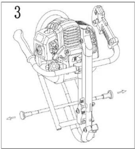
natural_image
Technical line drawing of a mechanical device with gears and levers (no text or symbols)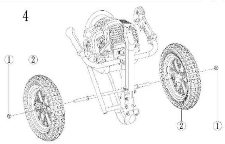
text_image
4 ① ② ③ ④ ⑤text_image
Technical diagram of a mechanical assembly with numbered parts for identificationnatural_image
Diagram showing a mechanical component with a red arrow pointing to a corner joint (no text or symbols present)text_image
Technical diagram of a vehicle with labeled parts A, B, and C, showing mechanical components and motion indicators.
natural_image
Red plastic pushpin and metallic nut on white background (no text or symbols)
natural_image
Close-up of a hand adjusting an orange plastic clip on a black metal bracket (no text or symbols visible)
natural_image
Close-up of hands adjusting a black mechanical component with an orange plastic clip (no text or symbols visible)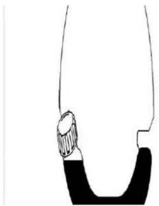
natural_image
Simple line drawing of a curved object with a textured base (no text or symbols)natural_image
Close-up of a mechanical component with orange plastic parts and a red arrow indicating a specific part (no visible text or symbols)
natural_image
Close-up of a mechanical component with orange plastic housing and a black plastic container (no visible text or symbols)natural_image
Close-up of a black and orange electric shock absorber with a hand adjusting its side panel (no text or symbols visible)5

natural_image
Close-up of a hand inserting a small component into a black industrial machine, with orange clamps and a red arrow indicating the action (no visible text or symbols)natural_image
Diagram of a mechanical device emitting particles or smoke, with no visible text or symbolsLIBÉRATION DU FIL DE COUPE EN NYLON

natural_image
Diagram of a naval gun firing from a ship deck, showing blade and gun components (no text or symbols)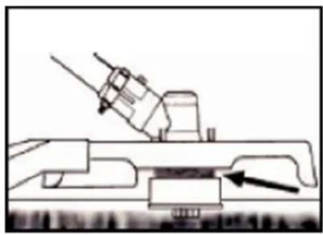
natural_image
Technical line drawing of a mechanical device with an arrow pointing to a component (no text or symbols present)natural_image
Technical diagram of a mechanical component with directional arrows indicating flow or movement (no text or symbols)text_image
1200mm (RMB 5.0A) 1200mm (RMB 5.0A)54. Plan de maintenance
natural_image
Close-up of a hand adjusting a black and orange FUMTEC device component (no visible text or symbols)text_image
0.6~0.7 mmnatural_image
Close-up of a mechanical component with labeled parts F and E, showing internal components and a ruler-like structure (no readable text or symbols beyond labels)
natural_image
Close-up of an orange plastic container being opened into a black industrial machine (no visible text or symbols)55. Stockage de la machine

Manual_FX-FSR162_Int24_rev2
natural_image
Simple line drawing of a tool with a handle and base (no text or symbols)Directives CE pertinentes: Directive Machines 2006/42/EU
natural_image
Technical line drawing of a mechanical measuring tool with attached sensors and wheels (no text or symbols)text_image
Technical diagram of a mechanical device with numbered components for identificationnatural_image
Technical line drawing of a mechanical assembly with no visible text or symbols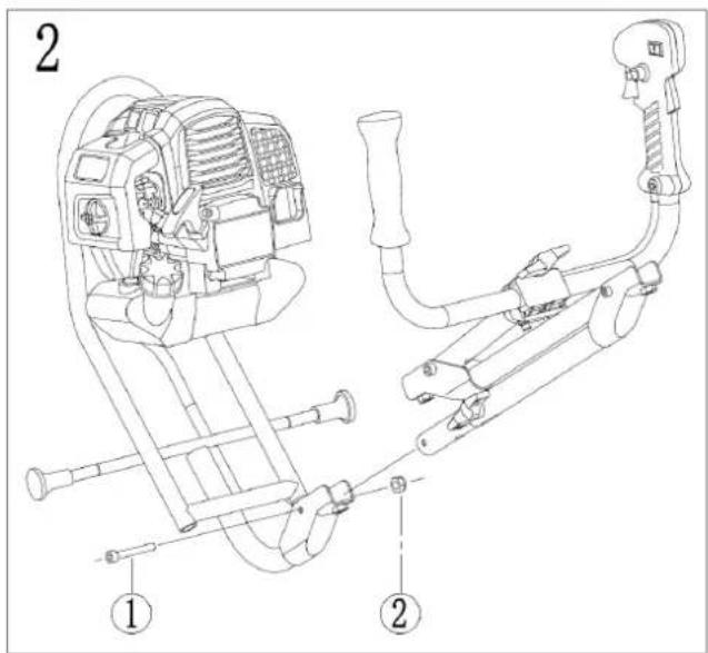
text_image
2 ① ②
natural_image
Technical line drawing of a mechanical device with no visible text or symbols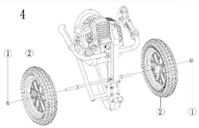
text_image
4 ① ② ③ ④ ⑤text_image
Technical diagram of a mechanical assembly with numbered parts for identification
natural_image
Diagram showing a mechanical component with a red arrow indicating direction, no text or symbols presentstringete la vite..
natural_image
Red and black plastic tool with threaded end, next to a metallic mesh nut (no text or symbols visible)
natural_image
Close-up of a hand adjusting a red plastic clip attached to a black metal bracket (no text or symbols visible)
natural_image
Close-up of hands adjusting a black tool with an orange plastic clip (no text or symbols visible)
natural_image
Close-up of a mechanical clamp with an orange handle and black rod (no text or symbols visible)natural_image
Close-up of a black handheld device with an orange handle and red arrow indicating a downward motion (no text or symbols)
natural_image
Close-up of a mechanical component with orange plastic parts and a red arrow indicating a directional change (no text or symbols visible)
natural_image
Close-up of an orange automotive component with a black plastic container and wiring, no visible text or symbolsnatural_image
Close-up of a black and orange electric shock absorber with a hand adjusting its internal components (no text or symbols visible)
natural_image
Close-up of a hand adjusting a black industrial machine component with orange clamps (no visible text or symbols)natural_image
Illustration of a naval gun firing from a ship deck, with no visible text or symbols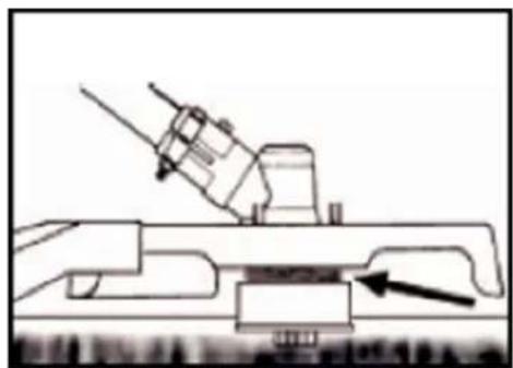
natural_image
Technical line drawing of a mechanical assembly with an arrow indicating a component (no text or symbols present)natural_image
Diagram of a mechanical device emitting particles or smoke, with arrows indicating direction (no text or symbols)TAGLIARE INTORNO GLI ALBERI
natural_image
Technical line drawing of a mechanical component with directional arrows indicating flow or movement (no text or symbols)text_image
Technical diagram of a mechanical component with directional arrows indicating rotation or movement, labeled in Chinese.natural_image
Close-up of a black and orange FUTTEC device with a hand adjusting its button (no visible text or symbols)
natural_image
Close-up of a black and orange plastic device with internal components, showing no visible text or symbols.Wartung Zündkerze
text_image
0.6~0.7 mmnatural_image
Close-up of a mechanical device with orange components and a worker inside (no visible text or symbols)natural_image
Technical line drawing of a mechanical measuring tool with attached sensors and wheels (no text or symbols)text_image
Technical diagram of a mechanical device with numbered parts for identificationnatural_image
Technical line drawing of a mechanical assembly with no visible text or symbols
text_image
2 ① ②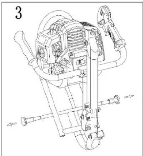
natural_image
Technical line drawing of a mechanical device with no visible text or symbols
text_image
4 ① ② ② ①text_image
Technical diagram of a mechanical assembly with numbered parts for identificationnatural_image
Diagram of a mechanical component with a red arrow indicating direction, no text or symbols presenttext_image
Technical diagram of a vehicle with labeled parts A, B, and C, showing mechanical assembly and suspension system.natural_image
Close-up of a red mechanical component with threaded screw and a metallic nut, no visible text or symbols.126

natural_image
Close-up of a hand adjusting a black cylindrical object with an orange plastic clip (no text or symbols visible)
natural_image
Close-up of hands adjusting a black tool with an orange plastic clip (no text or symbols visible)
natural_image
Close-up of a black pipe fitting with an orange plastic clip attached, no visible text or symbolsMEZCLA DE COMBUSTIBLE
natural_image
Close-up of a black and orange electric fan device with a hand adjusting its top panel, showing a red arrow pointing to the component (no text or symbols visible)5

natural_image
Close-up of a hand inserting a small component into a black industrial machine with orange clamps (no visible text or symbols)natural_image
Diagram of a mechanical device emitting particles or smoke, with arrows indicating direction (no text or symbols)EL HILO DE NYLON

natural_image
Technical diagram of a mechanical device with a downward arrow indicating force or motion (no text or symbols present)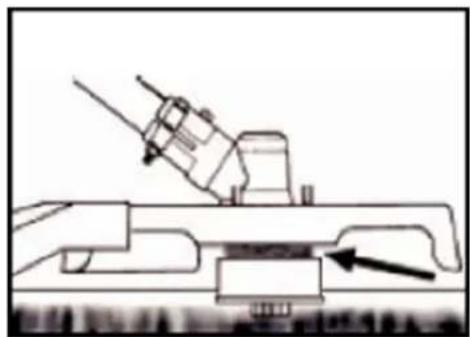
natural_image
Technical line drawing of a mechanical assembly with an arrow indicating a component (no text or symbols present)natural_image
Technical line drawing of a mechanical component with directional arrows indicating flow or movement (no text or symbols)natural_image
Close-up of a hand adjusting a black and orange electronic device component (no visible text or symbols)
natural_image
Close-up of a black and orange industrial device with internal components, showing no visible text or symbols.text_image
0.6~0.7 mmnatural_image
Close-up of a mechanical component with labeled parts F and E, showing internal components and a ruler (no text or symbols beyond labels)
natural_image
Line drawing of a hand holding a tool near a device (no text or symbols)natural_image
Technical line drawing of a mechanical measuring tool with attached components (no text or symbols)text_image
15m(50ft)MANTENHA SEMPRE A 15 METROS DE DISTÂNCIA DE OUTRA PESSOA DISTÂNCIA

O NÍVEL DE RUÍDO GARANTIDO ESTÁ EM CONFORMIDADE COM AS DIRETRIZES LEGAIS DE RUÍDO

text_image
Technical diagram of a mechanical device with numbered components for identificationnatural_image
Technical line drawing of a mechanical assembly with no visible text or symbols
text_image
2 ① ②
natural_image
Technical line drawing of a mechanical device with no visible text or symbols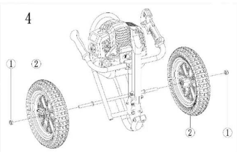
text_image
4 ① ② ② ①text_image
Technical diagram of a mechanical assembly with numbered parts for identificationnatural_image
Diagram showing a mechanical component with a red arrow pointing to a connector (no text or symbols present)text_image
Technical diagram of a vehicle with labeled parts A, B, and C, showing mechanical assembly and motion indicators.parafusos manualmente.

natural_image
Close-up of a red plastic tool with threaded screw and a metallic mesh nut on a plain background (no text or symbols visible)151

natural_image
Close-up of a hand adjusting a black cylindrical object with an orange handle (no visible text or symbols)natural_image
Close-up of a black and orange electric fan device with a hand adjusting its top panel, showing a red arrow pointing to the component (no text or symbols visible)5

natural_image
Close-up of a hand inserting a small component into a black industrial machine with orange clamps (no visible text or symbols)natural_image
Diagram of a wind turbine blade with blades and blades moving through it, showing airflow direction (no text or symbols)O FIO DE NYLON

natural_image
Technical diagram of a mechanical device with a downward arrow indicating force or motion (no text or symbols present)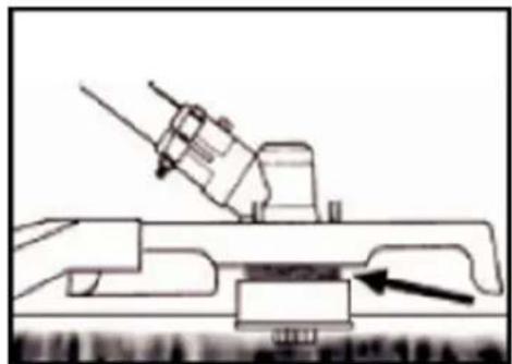
natural_image
Technical line drawing of a mechanical assembly with an arrow indicating a component (no text or symbols present)natural_image
Technical line drawing of a mechanical component with directional arrows indicating flow or movement (no text or symbols)text_image
100mm/100mm 100mm/100mmnatural_image
Close-up of a hand adjusting a black and orange electronic device component (no visible text or symbols)
natural_image
Close-up of a black and orange industrial device with internal components, showing no visible text or symbols.text_image
0.6~0.7 mmnatural_image
Close-up of a mechanical component with labeled parts F and E, showing a yellow surface and a ruler-like object (no text or symbols beyond labels)
natural_image
Line drawing of a hand holding a tool near a device (no text or symbols)natural_image
Technical line drawing of a mechanical measuring tool with attached components (no text or symbols)text_image
Technical diagram of a mechanical device with numbered components for identificationnatural_image
Technical line drawing of a mechanical assembly with no visible text or symbols
text_image
2 ① ②
natural_image
Technical line drawing of a mechanical device with no visible text or symbols
text_image
4 ① ② ② ①text_image
Technical diagram of a mechanical assembly with numbered parts for identificationnatural_image
Diagram showing a mechanical component with a red arrow pointing to a connector (no text or symbols present)text_image
Technical diagram of a mechanical device with labeled parts A, B, and C, showing assembly or maintenance instructions.
natural_image
Close-up of a red plastic tool with threaded screw and a metallic mesh nut on a plain white background (no text or symbols visible)176

natural_image
Close-up of a hand adjusting a black metal bracket with an orange plastic clip (no text or symbols visible)natural_image
Close-up of a black and orange electric fan device with a hand adjusting its top panel, showing a red arrow pointing to the component (no text or symbols visible)5

natural_image
Close-up of a hand inserting a small component into a black industrial machine with orange clamps (no visible text or symbols)natural_image
Diagram of a mechanical device emitting particles or smoke, with arrows indicating direction (no text or symbols)DE NYLON DRAAD

natural_image
Illustration of a naval gun firing from a ship deck, with no visible text or symbols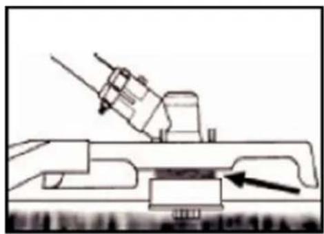
natural_image
Technical line drawing of a mechanical assembly with no visible text or symbolsnatural_image
Technical line drawing of a mechanical component with directional arrows indicating flow or movement (no text or symbols)text_image
100mm/100mm 100mm/100mmnatural_image
Close-up of a hand adjusting a black and orange FUNTEC-branded device with a knob (no visible text or symbols)
natural_image
Close-up of a mechanical device with orange handle and black casing, showing internal components (no text or symbols visible)Bougie onderhoud
text_image
0.6~0.7 mmnatural_image
Close-up of a mechanical component with labeled parts F and E, showing a yellow surface and a ruler-like object (no text or symbols beyond labels)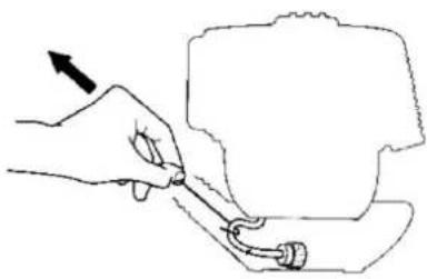
natural_image
Line drawing of a hand holding a tool near a device (no text or symbols)BESCHERMING TEGEN TRANSPORT
natural_image
Technical line drawing of a mechanical measuring tool with a mounted sensor and wheels (no text or symbols)text_image
15m(50ft)BERÖRING AV DET ROTERANDE BLADET FÖRBJUDET, SKADA
HÅLL ALLTID 15 METERS AVSTÅND FRÅN EN ANNAN PERSON AVSTÅND

DEN GARANTERADE LJUDNIVÅN ÖVERENSSTÄMMER MED DE LAGSTADGADE BULLERRIKTLINJERNA
| INGEN RÖKNING OCH ÖPPEN ELD PÅ ENHETEN |
| VARNING:FARA MED HETA KOMPONENTER |
| STÄNG AV ALWAYS-MASKINEN OCH SE TILL ATTSKÄRVERKTYGET ÄR STOPPAT INNAN DU RENGÖR, TAR BORTELLER JUSTERAR DET. |
| VARNING:AVGASER FRÅN DENNA PRODUKT INGÅRKEMIKALIER SOM ORSAKAR CANCER, FOSTERSKADOROCH KAN LEDA TILL MER |
| VARNING! BYT ALDRIG MASKIN. FELAKTIG ANVÄNDNING AVMASKINEN KAN ORSAKA ALLVARLIGA ELLER DÖDLIGAPERSONSKADOR. |
| VARNING! BRÄNNBARA MATERIAL |
| MAXIMAL SPINDELHASTIGHET (GRÄSTRIMMER): 6600 RPM |
| Montera anslutningsröret till motorn som visas i dennaillustration |
| Inga skärblad får användas med denna maskin |
VIKTIG
text_image
Technical diagram of a mechanical device with numbered components for identificationnatural_image
Technical line drawing of a mechanical assembly with no visible text or symbols
text_image
Technical diagram of a mechanical device with labeled parts, showing internal components and assembly steps.
natural_image
Technical line drawing of a mechanical device with no visible text or symbols
text_image
4 ① ② ② ①text_image
Technical diagram of a mechanical assembly with numbered parts for identification
natural_image
Diagram showing a mechanical component with a red arrow indicating direction, no text or symbols presentnatural_image
Close-up of a red plastic tool with threaded screw and a metallic nut on a plain background (no text or symbols visible)201

natural_image
Close-up of a hand adjusting a black cylindrical object with a red-orange plastic clip (no visible text or symbols)natural_image
Close-up of a mechanical component with orange plastic parts and a red arrow indicating a specific part (no visible text or symbols)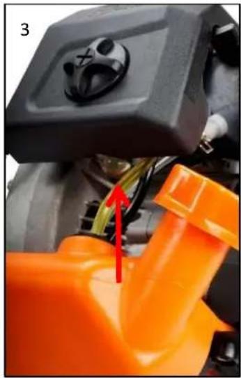
natural_image
Close-up of an orange automotive engine component with a black plastic tank and red arrow indicating a cable or connector (no text or symbols visible)natural_image
Close-up of a black and orange electric shock absorber with a hand adjusting its screwdriver (no text or symbols visible)5

natural_image
Close-up of a hand inserting a small component into a black industrial machine with orange base (no visible text or symbols)natural_image
Diagram of a wind turbine blade with motion arrows indicating wind direction (no text or symbols)NYLON TRÅDEN

natural_image
Technical line drawing of a naval gun on a ship deck with a downward arrow indicating force or impact (no text or symbols present)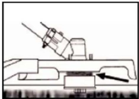
natural_image
Technical line drawing of a mechanical assembly with an arrow indicating a component (no text or symbols present)natural_image
Technical line drawing of a mechanical component with directional arrows indicating flow or movement (no text or symbols)text_image
100mm/100mm 100mm/100mmnatural_image
Close-up of a hand adjusting a black and orange electronic device component (no visible text or symbols)
natural_image
Close-up of a black and orange industrial device with internal components, showing no visible text or symbols.text_image
0.6~0.7 mmnatural_image
Close-up of a mechanical component with labeled parts F and E, showing internal components and a ruler (no text or symbols beyond labels)
natural_image
Line drawing of a hand holding a tool near a device (no text or symbols)POLSKA WERSJA JEZYKOWA
ORYGINALNA INSTRUKCJA OBSŁUGI
Podkaszarka kołowa
FX-FSR162

natural_image
Technical line drawing of a mechanical measuring tool with a mounted cart and guide rail (no text or symbols)text_image
Technical diagram of a mechanical device with numbered parts for identificationnatural_image
Technical line drawing of a mechanical assembly with no visible text or symbols
text_image
2 ① ②
natural_image
Technical line drawing of a mechanical device with no visible text or symbols
text_image
4 ① ② ② ①text_image
Technical diagram of a mechanical assembly with numbered parts for identification
natural_image
Diagram showing a mechanical component with a red arrow pointing to its end, no text or symbols presenttext_image
Technical diagram of a vehicle's internal components with labeled parts A, B, and C
natural_image
Red and black plastic tool with threaded end, next to a metallic nut (no text or symbols visible)227

natural_image
Close-up of a hand adjusting an orange plastic clip attached to a black metal pipe fitting (no text or symbols visible)natural_image
Close-up of a mechanical component with orange components and a red arrow indicating a specific part (no visible text or symbols)
natural_image
Close-up of an orange automotive engine component with a black plastic tank and red arrow indicating a cable or connector (no text or symbols visible)natural_image
Close-up of a black and orange electric shock absorber with a hand adjusting its cable (no text or symbols visible)5

natural_image
Close-up of a hand inserting a small component into a black industrial machine with orange buttons (no visible text or symbols)natural_image
Diagram of a mechanical device emitting particles with motion arrows indicating flow (no text or symbols)NIĆ NYLONOWA

natural_image
Technical line drawing of a naval gun on a ship deck with a downward arrow indicating force or impact (no text or symbols present)
natural_image
Technical line drawing of a mechanical assembly with an arrow indicating a component (no text or symbols present)natural_image
Technical line drawing of a mechanical component with directional arrows indicating flow or movement (no text or symbols)natural_image
Close-up of a hand adjusting a black and orange electronic device component (no visible text or symbols)