
AquaMax Eco Titanium 31000 - Water pump OASE - Free user manual and instructions
Find the device manual for free AquaMax Eco Titanium 31000 OASE in PDF.

| Product Type | Pond Water Pump |
| Brand | Oase |
| Model | AquaMax Eco Titanium 31000 |
| Dimensions (L × W × H) | 275 × 175 × 200 mm |
| Weight | 9.2 kg |
| Mains Voltage | 220-240 V AC, 50/60 Hz |
| Power Consumption | 35-170 W |
| Max. Flow Rate | 31 500 l/h |
| Max. Delivery Head | 3.3 m |
| Max. Immersion Depth | 4 m |
| Cable Length | 10 m |
| Permissible Water Temperature | +4 to +35 °C |
| Max. Ambient Temperature (dry installation) | +30 °C (natural convection), +40 °C (forced cooling) |
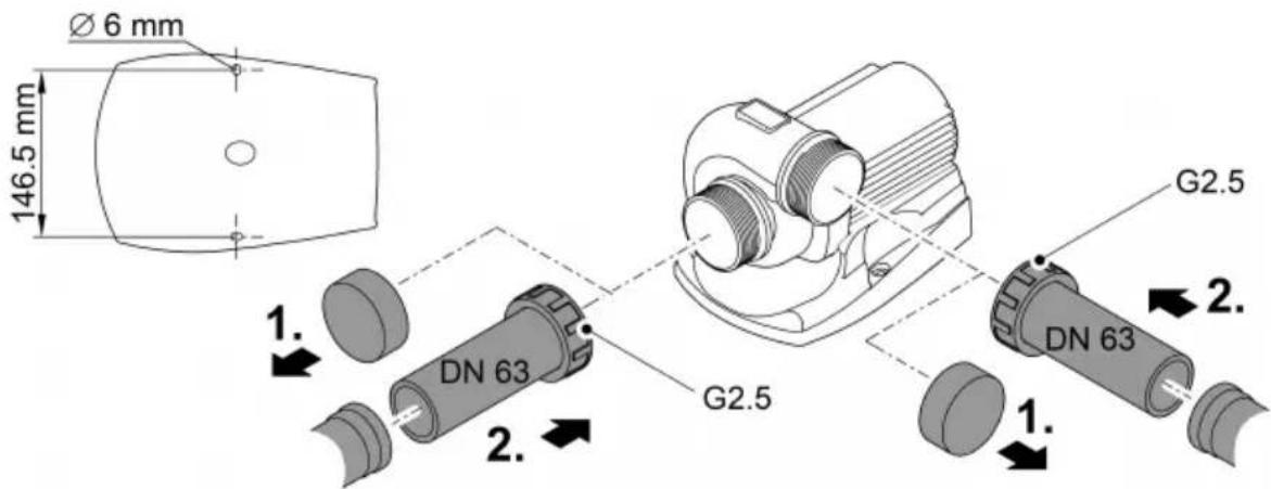
| Inlet/Outlet Connections | Thread G2 1/2, for DN63 piping |
| Max. Grain Diameter of Impurities | 6 mm |
| Smart Functions | SFC (Seasonal Flow Control), EFC (Environmental Function Control) |
| Control Compatibility | Eco Control, InScenio FM-Master, Garden Controller (via OASE Control) |
| Protection Rating | IP68 (waterproof up to 4 m) |
| Housing Material | Titanium (pump body) |
| Maintenance and Cleaning | Clean at least twice a year with clear water; use OASE PumpClean in case of limescale |
| Wear Parts | Operating unit, bearing in motor block |
| Safety | Protection by residual current device (30 mA), do not use in a natural swimming pool, minimum distance of 0.2 m for cardiac implants |
| Use | Pumping pond water for filters, waterfalls, streams; do not use for drinking water, chemicals or flammable liquids |
Frequently Asked Questions - AquaMax Eco Titanium 31000 OASE
User questions about AquaMax Eco Titanium 31000 OASE
0 question about this device. Answer the ones you know or ask your own.
Ask a new question about this device
Download the instructions for your Water pump in PDF format for free! Find your manual AquaMax Eco Titanium 31000 - OASE and take your electronic device back in hand. On this page are published all the documents necessary for the use of your device. AquaMax Eco Titanium 31000 by OASE.
USER MANUAL AquaMax Eco Titanium 31000 OASE
natural_image
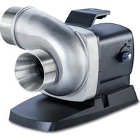
Black-and-white photo of three industrial heat exchangers with metallic blades and mounting brackets (no visible text or symbols)AquaMax Eco Titanium
31000, 51000, 81000
EN Operating instructions
FR Notice d'emploi
AquaMax Eco Titanium 81000
AMX0049
AMX0038
AMX0104
AquaMax Eco Titanium
AMX0052
AquaMax Eco Titanium 51000
DE

AquaMax Eco Titanium 81000

AMX0100
Garden Controller Home/Cloud
AMX0042
AquaMax Eco Titanium 31000

AMX0051
AquaMax Eco Titanium 51000

AquaMax Eco Titanium 81000

HINWEIS
Environmental Function Control (EFC)
AquaMax Eco Titanium 51000


AMX0102
Lagern/Überwintern
▶ Disconnect all electrical devices in the water from the power supply before reaching into the water. Otherwise there is a risk of severe injuries or death by electrocution.
This unit can be used by children aged 8 and above and by persons with reduced physical, sensory or mental capabilities or lack of experience and knowledge if they are supervised or have been instructed on how to use the unit in a safe way and they understand the hazards involved. Do not allow children to play with the unit. Only allow children to carry out cleaning and user maintenance under supervision.
Safety information
Electrical connection
- Special regulations apply for electrical installation in outdoor spaces. Only a qualified electrician may perform the electrical installation.
- The qualified electrician has the necessary professional training, knowledge and experience to perform electrical installation in outdoor spaces. The electrician can detect potential dangers and knows how to adhere to regional and national standards, regulations and directives.
— For your own safety, please consult a qualified electrician.
- Only connect the unit if the electrical data of the unit and the power supply match.
- Only plug the unit into a correctly installed outlet.
- The device is to be supplied through a residual current device (RCD) having a rated residual operating current not exceeding 30 mA.
- Extension cables and power distributors (e.g. outlet strips) must be suitable for outdoor use (splash-proof).
- Protect open plugs and sockets from moisture.
Safe operation
- Do not use the unit, if electrical lines or the housing are damaged.
- The supply cord cannot be replaced. If the cord is damaged, the appliance should be scrapped.
- The impeller unit in the pump contains a magnet with a strong magnetic field that may affect the operation of pacemakers or implantable cardioverter defibrillators (ICDs). Keep a distance of at least 0.2 m between the implant and the magnet.
- Do not carry or pull the unit by its power cable.
- Route lines in such a way that they are protected from damage and do not present a tripping hazard.
- Never carry out technical changes to the unit.
- Only carry out work on the unit that is described in this manual.
- Only use original spare parts and accessories.
- Should problems occur, please contact the authorised customer service or OASE.
Intended use
Only use the product described in this manual as follows:
- For pumping normal pond water for filter systems, waterfall systems and water course systems.
- While adhering to the technical specifications.
- Adherence to the permissible water quality.
The following restrictions apply to the unit:
- Do not use in swimming ponds.
- Never use the unit with fluids other than water.
- Never run the unit without water.
- Do not use in conjunction with chemicals, foodstuff, easily flammable or explosive substances.
- Do not connect to the domestic water supply.
- Do not use for commercial or industrial purposes.
- According to EMC (Electromagnetic Compatibility), this is a class A unit. The unit may cause malfunctions in living environments. It is the user's responsibility to take suitable counter-measures.
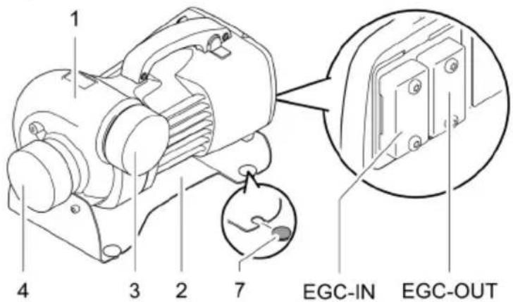
Product Description
Overview
AquaMax Eco Titanium 31000
AquaMax Eco Titanium 31000
AquaMax Eco Titanium 51000
AquaMax Eco Titanium 81000
AquaMax Eco Titanium 81000

AquaMax Eco Titanium
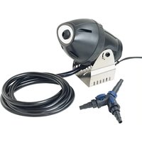
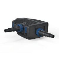
| 31000 | 51000 | 81000 | Description | ||
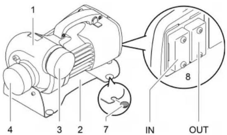
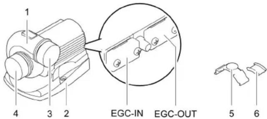
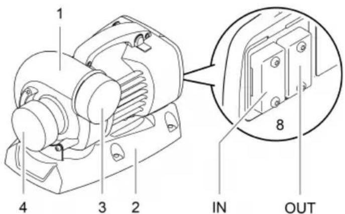
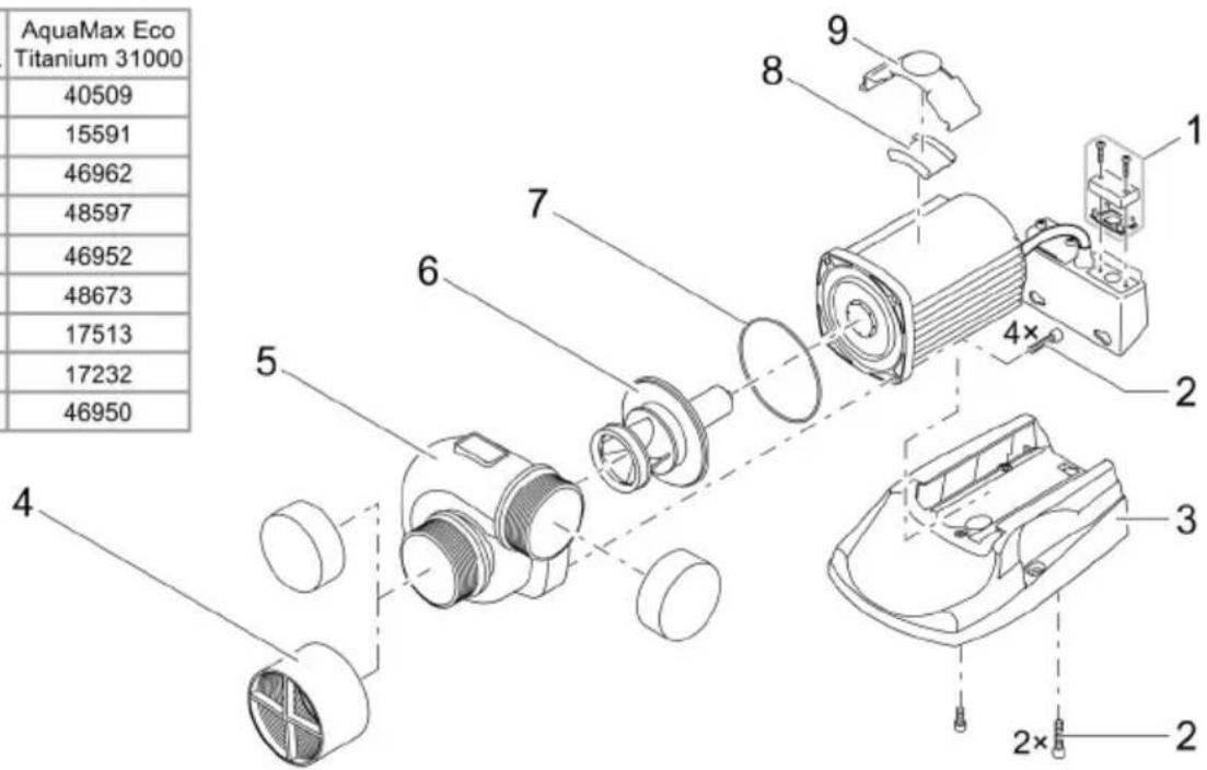
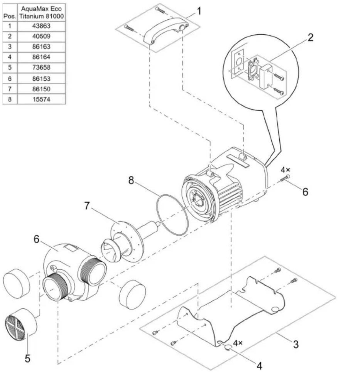
| 1 | ● | ● | ● | Pump casingThe pump casing can be turned by 90°. | |
| 2 | ● | ● | ● | StandEnsures a stable position. Screwing the stand to the ground is possible. | |
| 3 | ● | ● | ● | Outlet(pressure socket) | Keep the protective caps.To prevent serious injury while the pump is running, immediately attach the protective cap after you have removed a connected pipe. |
| 4 | ● | ● | ● | Inlet(suction socket) | |
| 5 | ● | - | - | Clip attachment for fastening the OASE Eco Control. | |
| 6 | ● | - | - | Rubber element for the clip attachment | |
| 7-- | ● | Rubber footRemovable if the stand is to be screwed to the ground. | |||
| 8 | ● | ● | ● | Control system connectionThe control unit OASE Eco Control (accessories) is required to operate the pump.Alternatively, the pump can be integrated in an OASE Control network.For information on OASE Control, visit www.oase.com. | |
Symbols on the unit
IP68

The unit is dust-tight and water-tight down to 4 m.


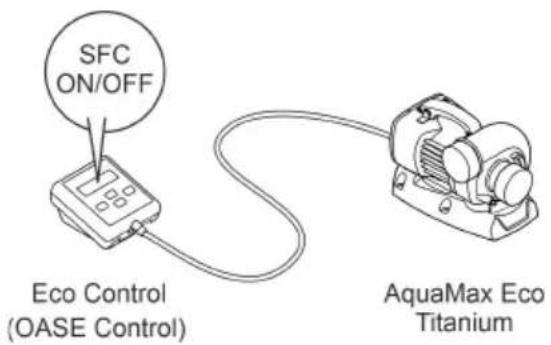
Seasonal Flow Control (SFC)
The SFC function intelligently controls the water volume or pump head based on the water temperature. This means the pump adapts to the individual pond ecology throughout the year and supports the pond biology through temperature-dependent circulation (winter mode, transition mode and summer mode).
- If the SFC function is active, the pump differentiates between ...
- winter mode (water temperature lower than +10 °C)
- transition mode (water temperature +10 ... +17 °C)
- summer mode (water temperature greater than +17 °C)
You can find the specific parameters at www.oase.com in the product section "Pond pumps".
- The SFC function may only be activated if the pump is submersed!
- If a skimmer or satellite filter is used, it may, depending on the system, be advisable to deactivate the SFC function.
- The SFC function is deactivated on delivery.
Switching ON/switching OFF
AMX0181
Installation and connection
The pump can be installed submerged (in water) or dry (outside the water).
WARNING
Severe injuries or death due to operation of this unit in a swimming pond. Defective electrical components will electrify the water with dangerous electrical voltage.
▶ Never operate the unit in a swimming pond.
Avoid exposing any unit components to direct sunlight for extended periods of time, as this can lead to damage. If necessary, use a protective cover.
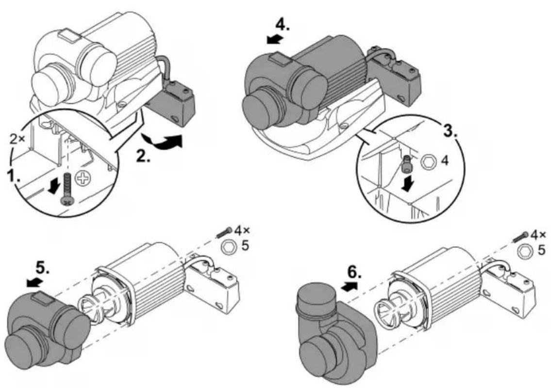
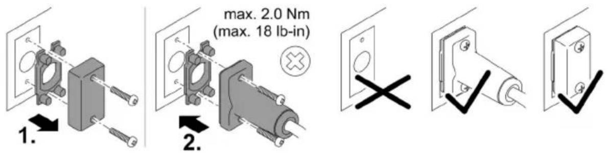
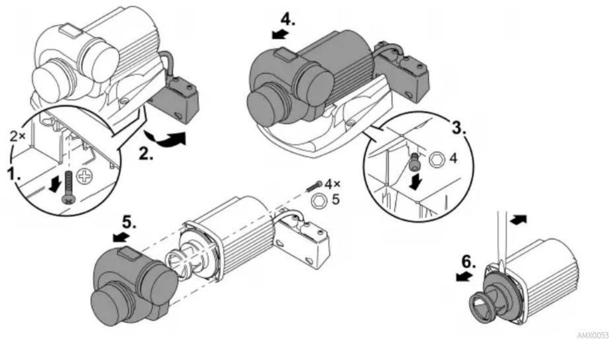
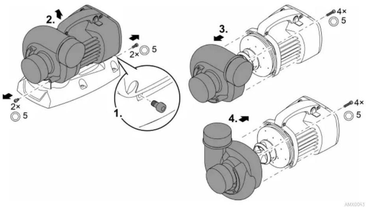
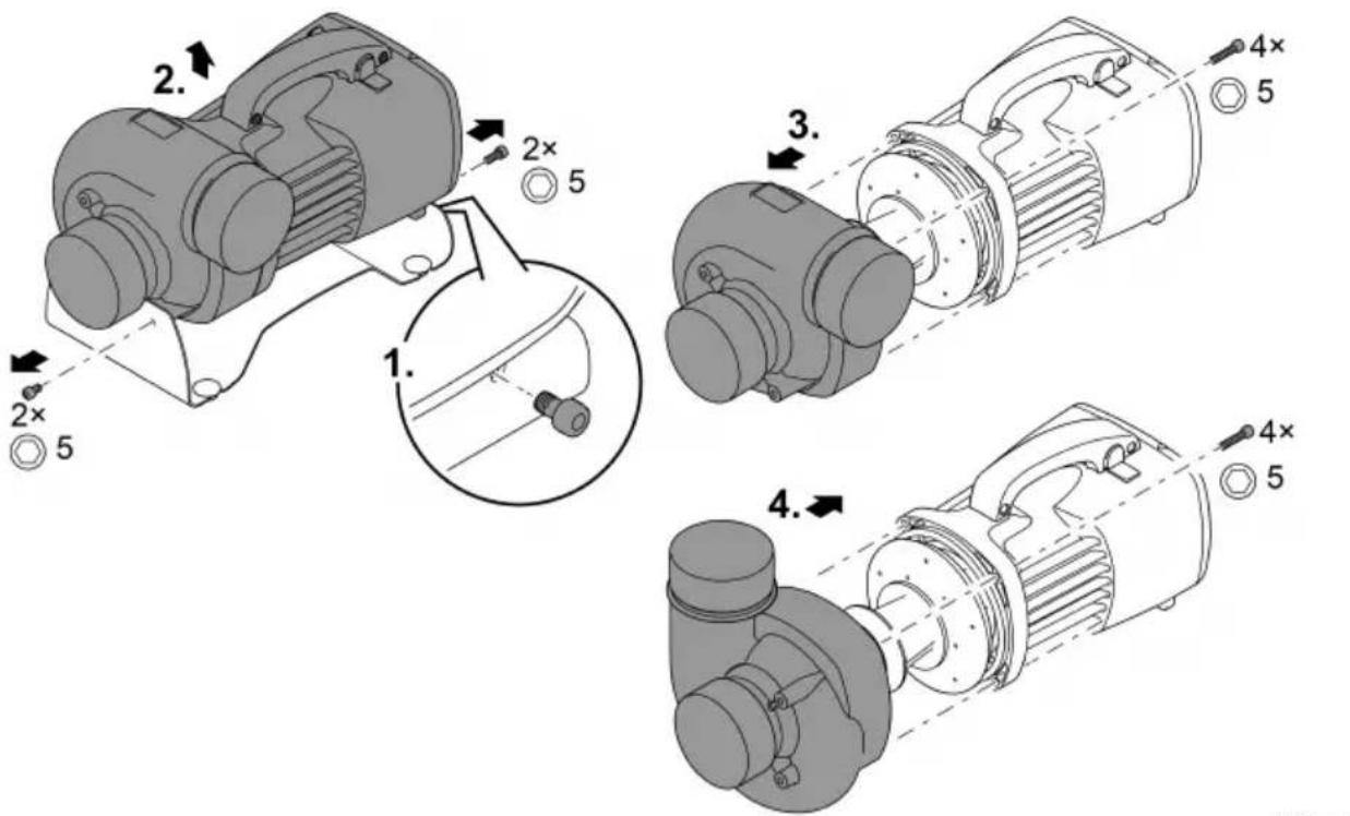
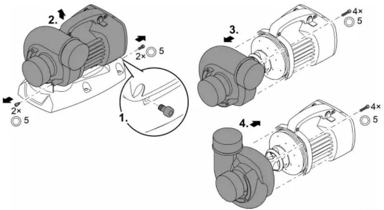
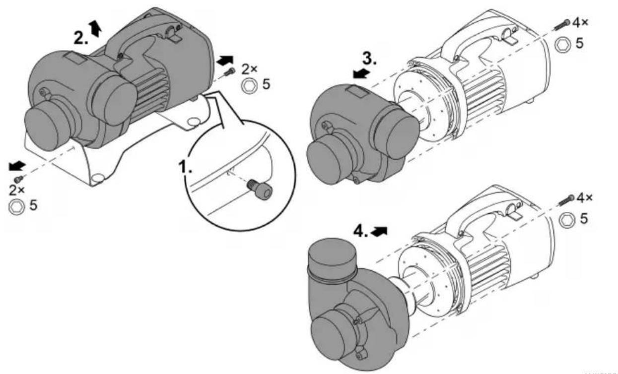
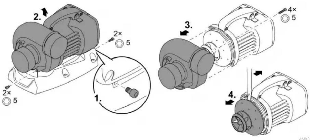
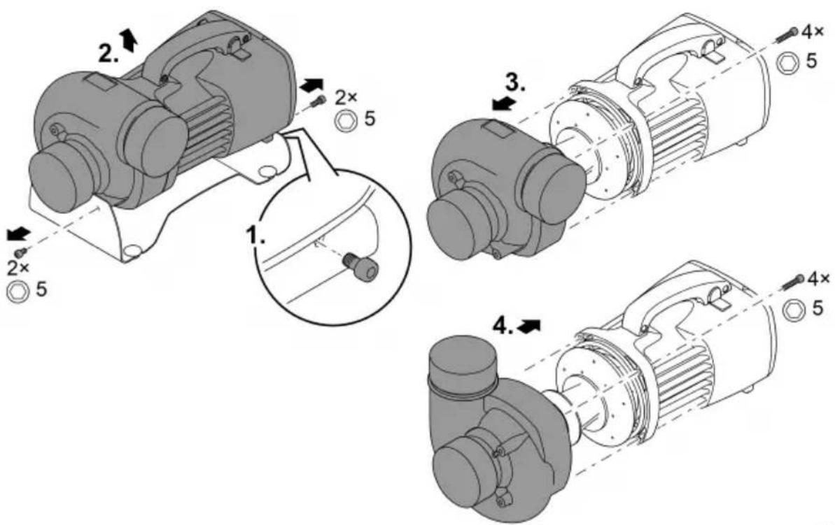
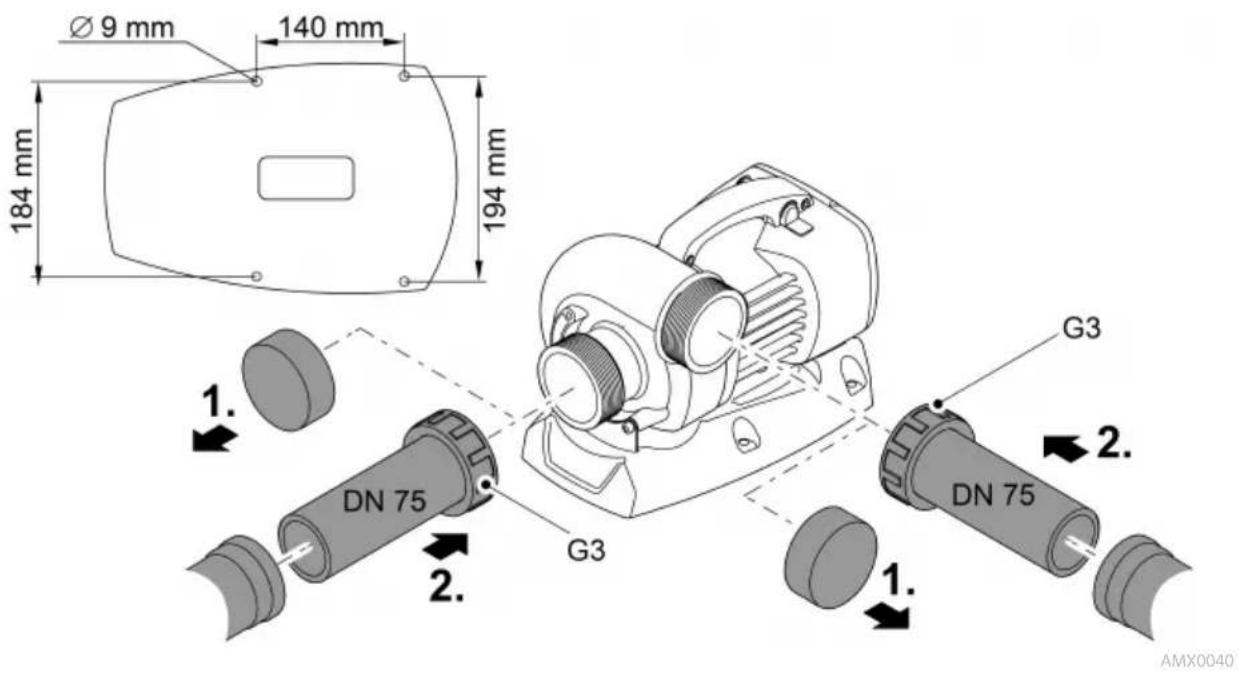
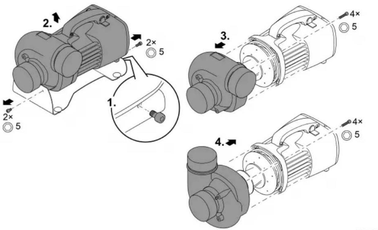
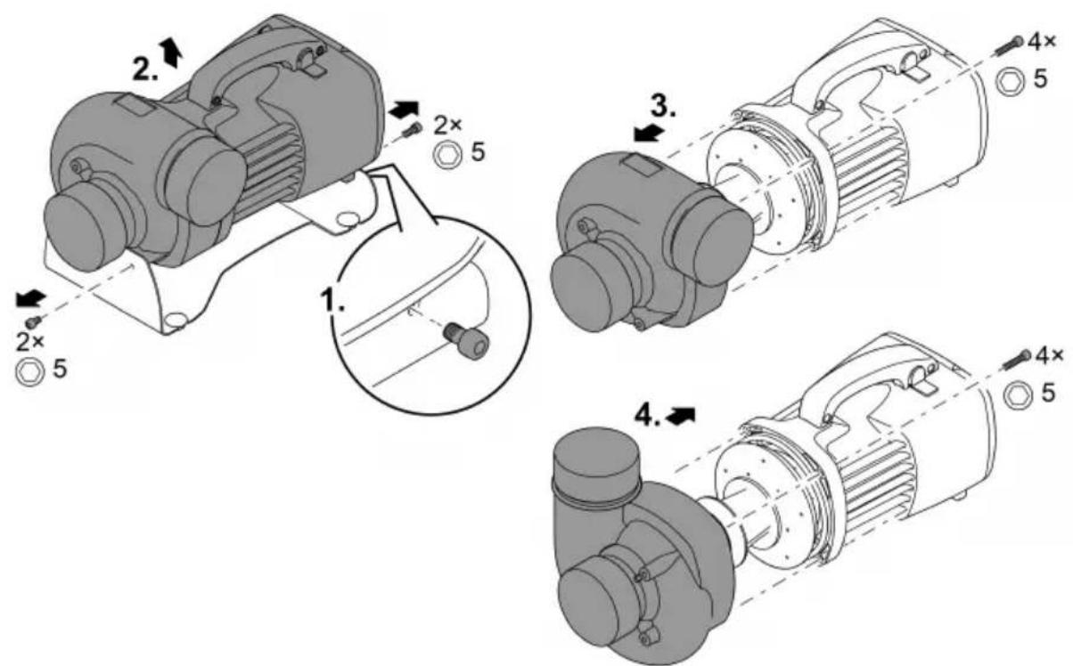
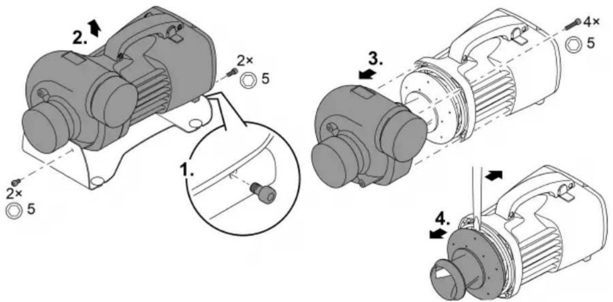
Turning the pump casing to achieve a different position
If necessary, the pump casing can be turned to change the position of the pump outlet by 90°.
- The pump casing can only be mounted in the two positions indicated.
- Reassemble the pump in the reverse order.
- Tightening torque for all loosened screws: 3 Nm
EN
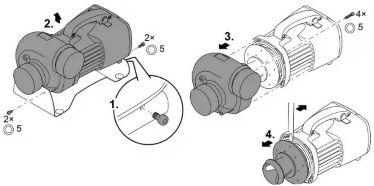
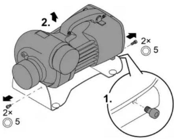
NOTE
If the pump housing jams when it is removed and pushes against the impeller unit, this will damage the impeller unit.
▶ Position the pump vertically before removing the pump housing. This ensures that the weight of the pump housing can no longer push against the impeller unit.
▶ Carefully pull the motor block off the pump housing, ensuring that it is kept straight.
▶ Proceed equally carefully during assembly.
AquaMax Eco Titanium 31000
AMX0052
AquaMax Eco Titanium 51000

AquaMax Eco Titanium 81000

AMX0100
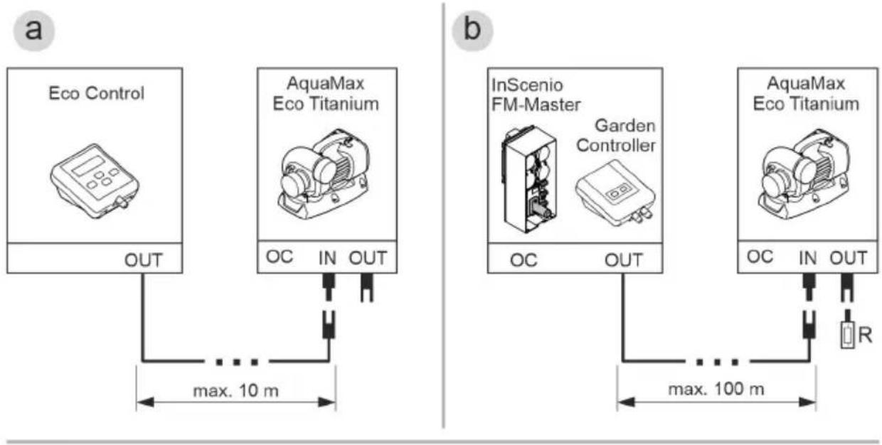
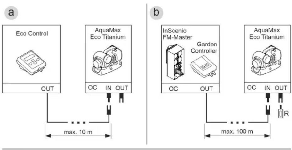
Connecting the control system
The pump can be operated with or without the control system.
- The control system makes it possible to regulate the pump power.
- Without the control system, the pump runs permanently at full power.
Compatible control systems (accessories):
- Eco Control
Intelligent control system for one pump.
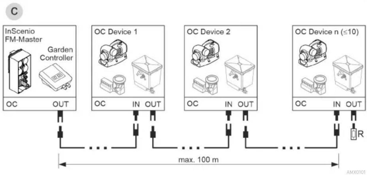
• Incenio FM-Master Home/Cloud
Garden Controller Home/Cloud
Up to 10 OASE Control-compatible units (pumps, filters, lights) can be controlled using the "OASE Control" app.
For information on this topic, visit www.oase.com and navigate to the section "Smart garden controls and lighting".
flowchart
graph LR
    A["InScenio FM-Master"] -->|OC OUT| B["..."]
    C["GC"] --> D["IN OUT"]
    E["Garden Controller"] --> F["..."]
    G["OC Device 1"] --> H["IN OUT"]
    I["OC Device 2"] --> J["IN OUT"]
    K["OC Device n (≤10)"] --> L["IN OUT"]
    M["R"] --> N["OUT"]
    B -->|max. 100 m| N
    H -->|max. 100 m| N
    L -->|max. 100 m| N
    N --> O["AMX0101"]
- An OASE Control network (variant B, C) must end with a terminal resistor R. The terminal resistor is included with the InSenio FM-Master or Garden Controller.
PLX0004
NOTE
The unit will be damaged, if water enters the plug connector.
▶ Connect the plug connector or place the protective cap on it.
▶ Ensure that the rubber seal is clean and fits exactly.
▶ If the rubber seal is damaged, it must be replaced. When the plug connector is disconnected, the rubber seal must be replaced if it is older than 2 years.
▶ Always secure the plug connector or the protective cap with the two screws.
Submerged installation of the pump
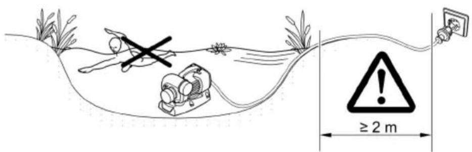
- Ensure that the power cables and mains sockets are at least 2 m from the water.
- For installation of the pump in a pump chamber (recommended):
- For a swimming pond or pool frequented by swimming people, install the pump chamber at least 2 m from the water.
- Install the pump horizontally.
— Screw the stand to the floor of the pump chamber to ensure the stability of the pump.
- For installation of the pump without a pump chamber:
— Place the pump horizontally on a stable, mud-free surface.
- Ensure secure and stable positioning of the pump.
- Only operate the pump when it is fully submerged.
- For muddy or soiled water, we recommend installing the pump or intake-side components (skimmer, satellite filter, base outlet, etc.) above ground level. This decreases intake of particles and increases the service life of the impeller unit.
- Pool water or salt water can impair the appearance of the unit. Such impairments are excluded from the guarantee.
AMX0063
Dry installation of the pump
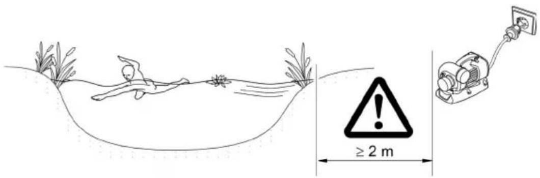
- Ensure that the power cables and mains sockets are at least 2 m from the water.
- For a swimming pond or pool frequented by swimming people, install the pump at least 2 m from the water.
- Place the pump horizontally on a stable surface.
- Ensure secure and stable positioning of the pump. If necessary, screw the stand to the ground.
- Protect the pump from direct sunlight.
- Adhere to the maximum permissible ambient temperature. If necessary, provide forced cooling.
AMX0037
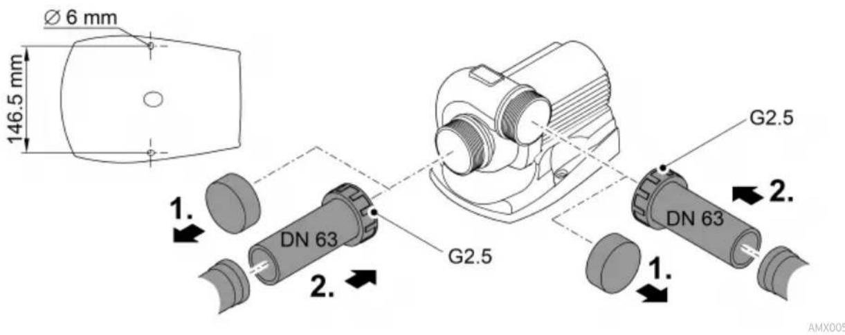
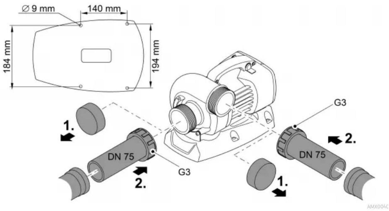
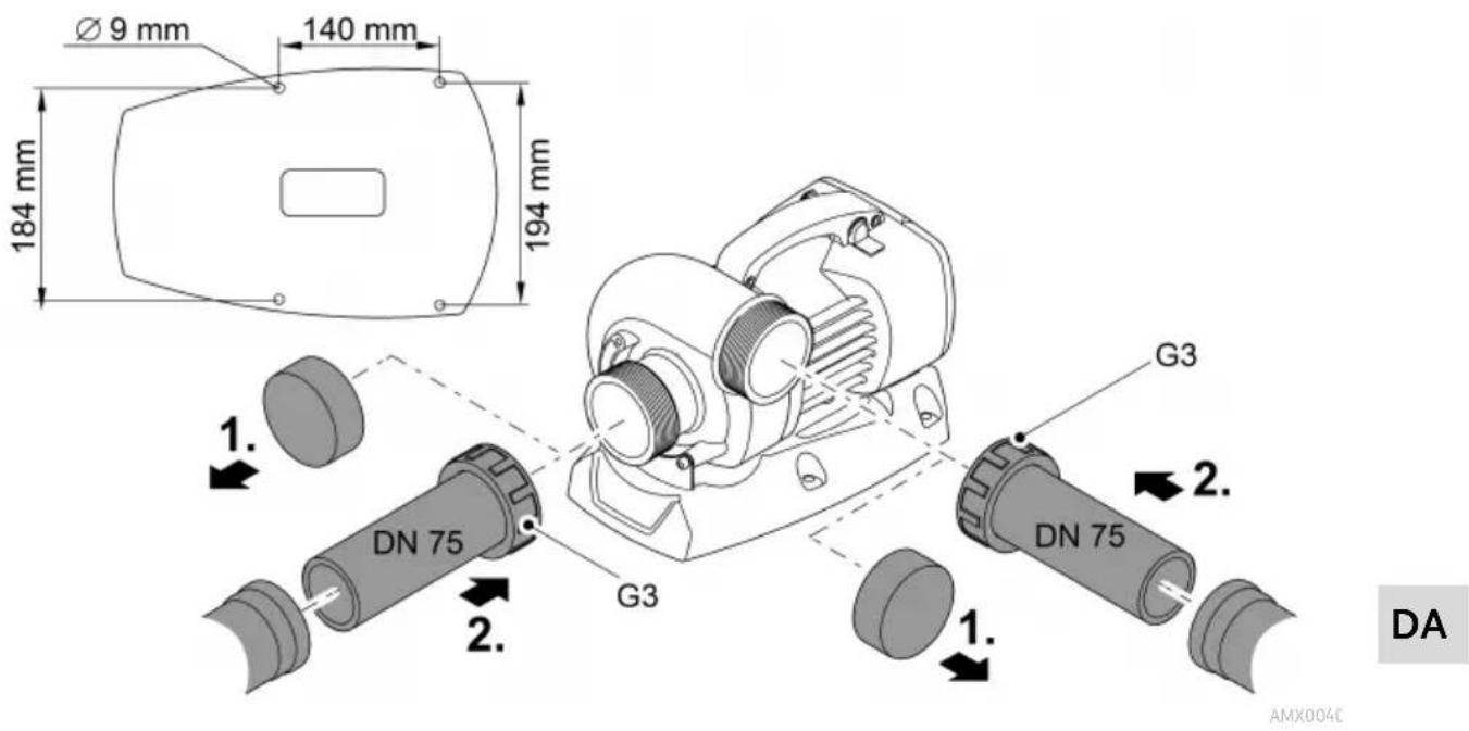
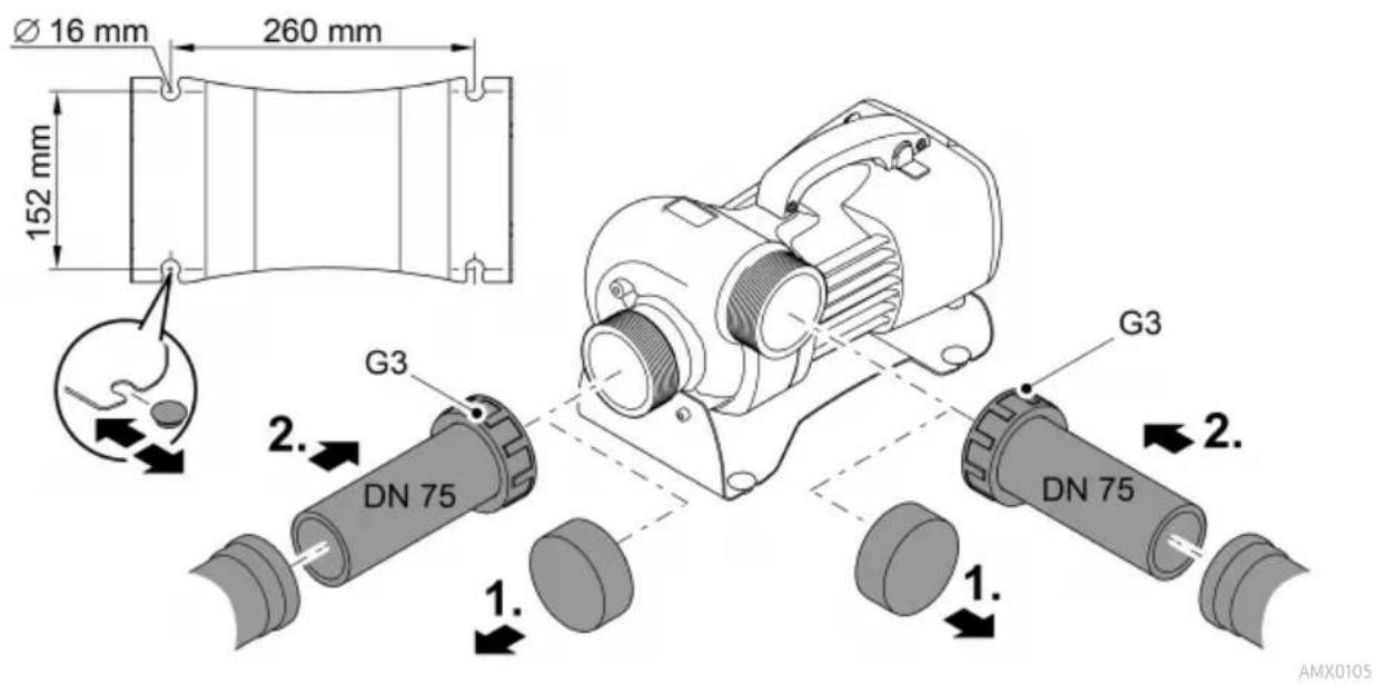
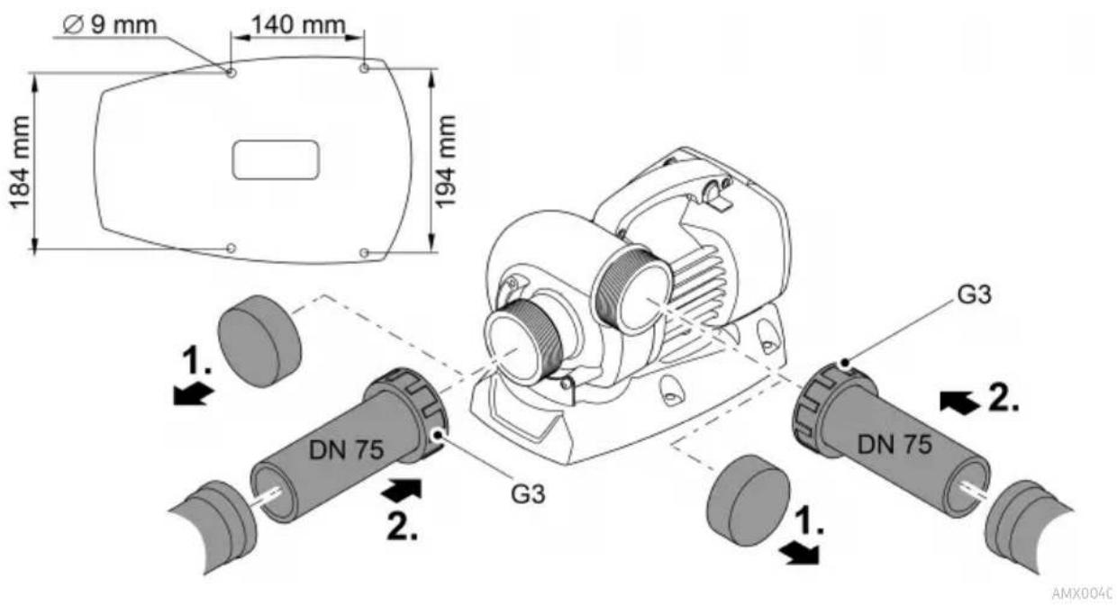
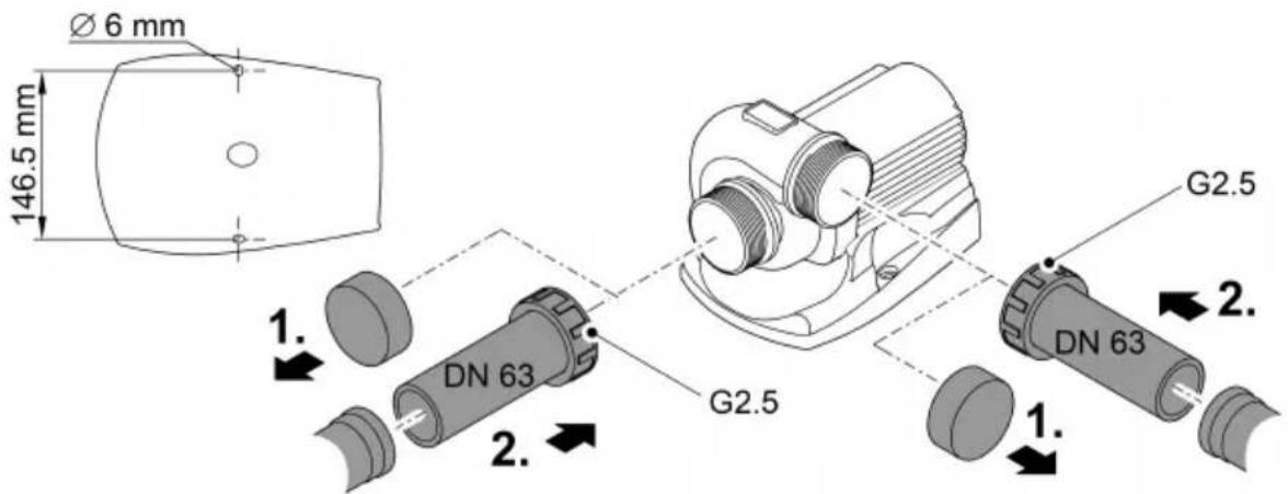
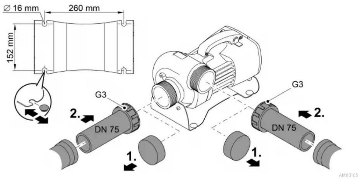
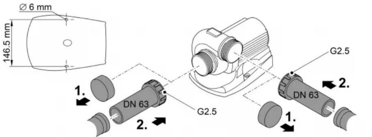
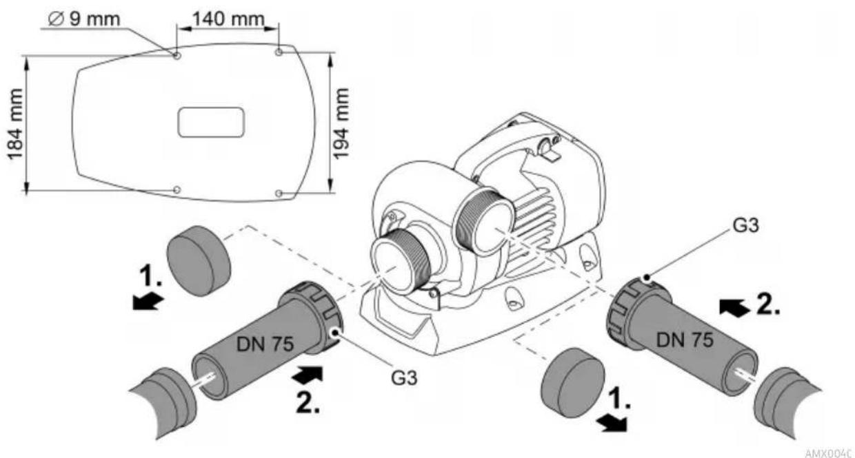
Connecting the pressure side/suction side

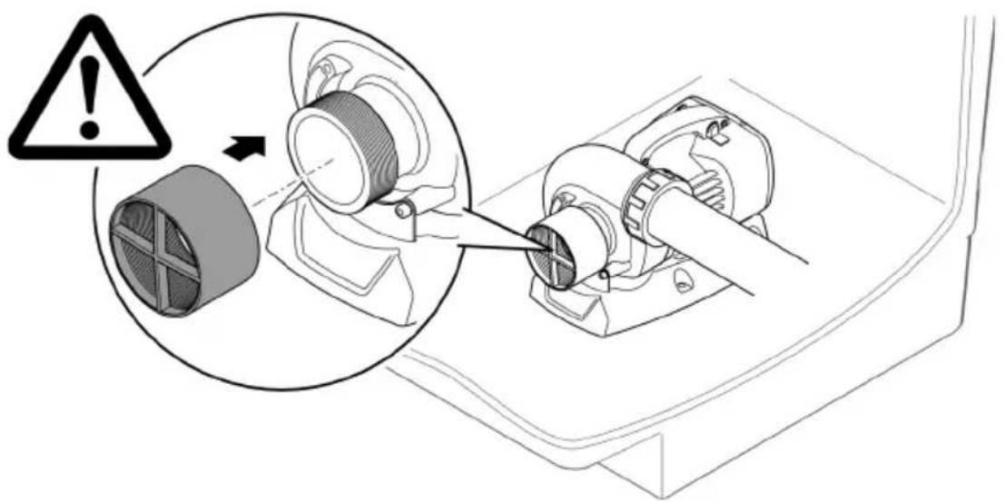
WARNING
The impeller unit rotates very fast. Do not reach into the openings of the suction socket or pressure socket as there is a risk of severe injury such as loss of limb.
▶ Secure the suction socket/pressure socket with a hand guard if no pipe is connected. The hand guard is available as an accessory (AquaMax Eco Titanium 31000: 48597, AquaMax Eco Titanium 51000, 81000: 73658).
▶ Place the pump in a pump chamber and secure access to the pump chamber (use a padlock or screws to secure the access point).
AMX0042
AquaMax Eco Titanium 31000

AMX0051
AquaMax Eco Titanium 51000

AquaMax Eco Titanium 81000

Commissioning/start-up
NOTE
The unit will be destroyed if it is operated with a dimmer. It contains sensitive electrical components.
▶ Do not connect the unit to a dimmable power supply.
NOTE
Never allow the pump to run dry. Otherwise the pump may be destroyed.
▶ Only operate the pump when it is submerged or flooded.
Switching ON/OFF
- Switching on: Plug the power plug into the outlet.
— The unit switches on immediately.
- Switching off: Pull the power plug from the outlet.
Environmental Function Control (EFC)
When started up and then every 20 ... 40 minutes the pump automatically performs a pre-programmed self-test (Environmental Function Control (EFC)). The pump detects if it is running dry / clogged or submerged. The pump shuts down automatically after 60 to 120 seconds if it runs dry/is blocked. In the event of a malfunction, disconnect the power supply and “flood the pump” or remove the obstacle. Afterwards, the unit can be restarted.
Maintenance and cleaning

CAUTION
Risk of injury due to unexpected start-up. Internal monitoring functions may switch off the unit and automatically reactivate it.
▶ Disconnect the power plug before carrying out any work on the unit.
NOTE
Do not use aggressive cleaning agents or chemical solutions. These agents can damage the housing, impair the function of the device and harm animals, plants and the environment.
▶ If possible, clean the unit with clear water and a soft brush or a sponge; remove stubborn dirt with the aid of the recommended cleaning agents.
Cleaning the device
i Clean the unit as required but at least twice per year.
- When cleaning the pump, pay particular attention to the impeller unit and the pump housing.
- Recommended cleaning agent for removing stubborn limescale deposits:
- Pump cleaning agent PumpClean from OASE.
— Vinegar- and chlorine-free household cleaning agent.
• After cleaning, thoroughly rinse all parts in clean water.
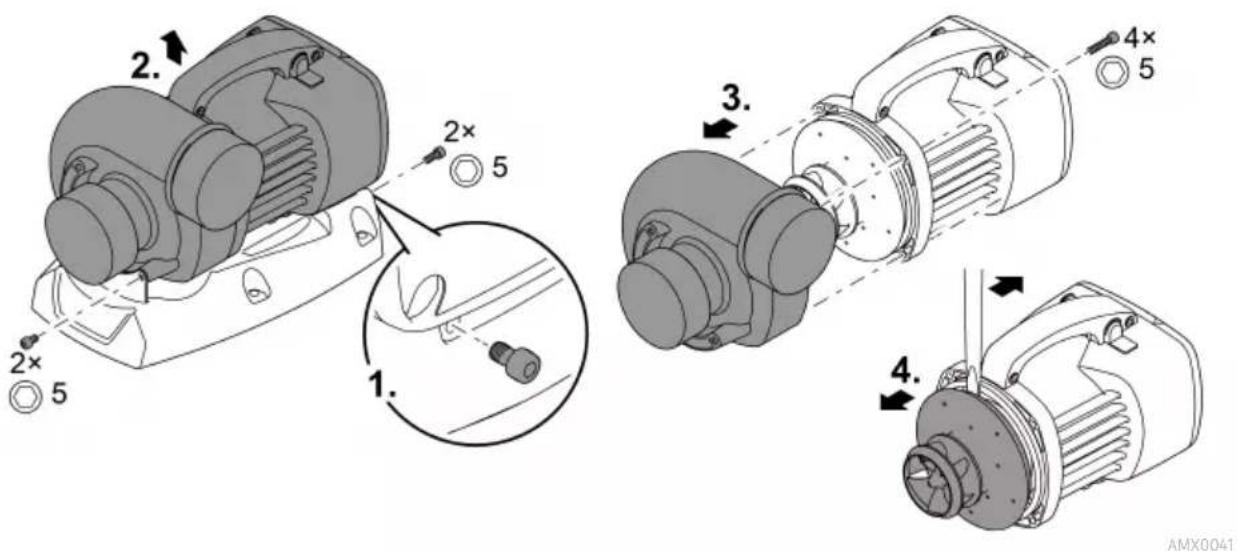
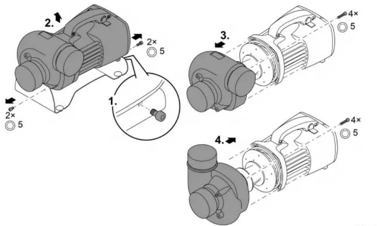
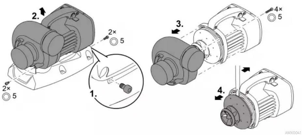
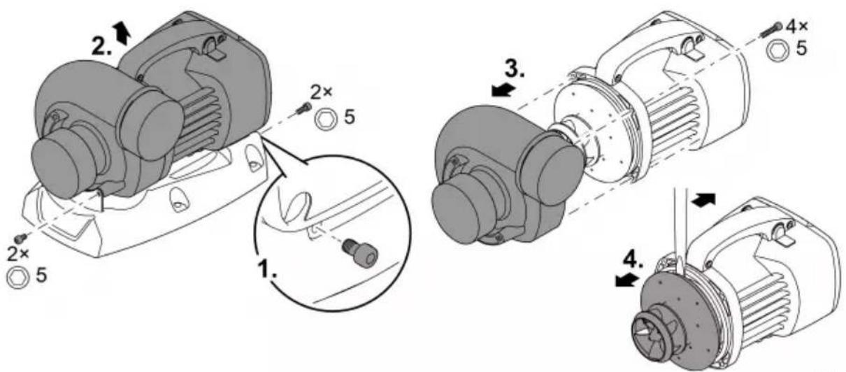
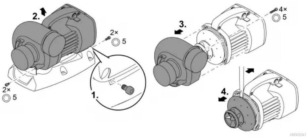
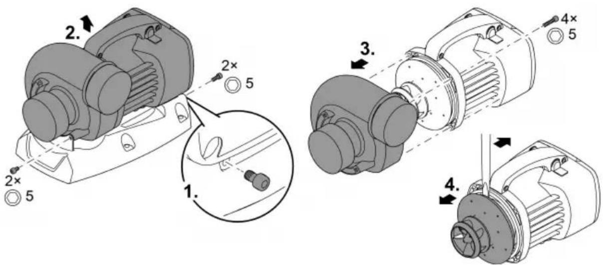
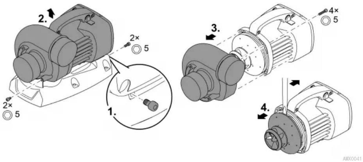
Cleaning/replacing the impeller unit

WARNING
The impeller unit rotates very fast. Do not reach into the openings of the suction socket or pressure socket as there is a risk of severe injury such as loss of limb.
▶ Disconnect the power plug before carrying out any work on the unit.
NOTE
The impeller unit contains strong magnets that attract magnetic particles (e.g. iron filings). Any remaining particles can cause irreparable damage to the impeller unit and motor block.
▶ Carefully remove any adhering particles from the impeller unit prior to installation.
NOTE
The impeller unit is guided in the motor block by a bearing. This bearing is a wear part and should be changed at the same time as the impeller unit.
▶ Changing the bearing requires specialist knowledge and tools. Have the bearing changed by the OASE specialist dealer or send the pump to OASE.
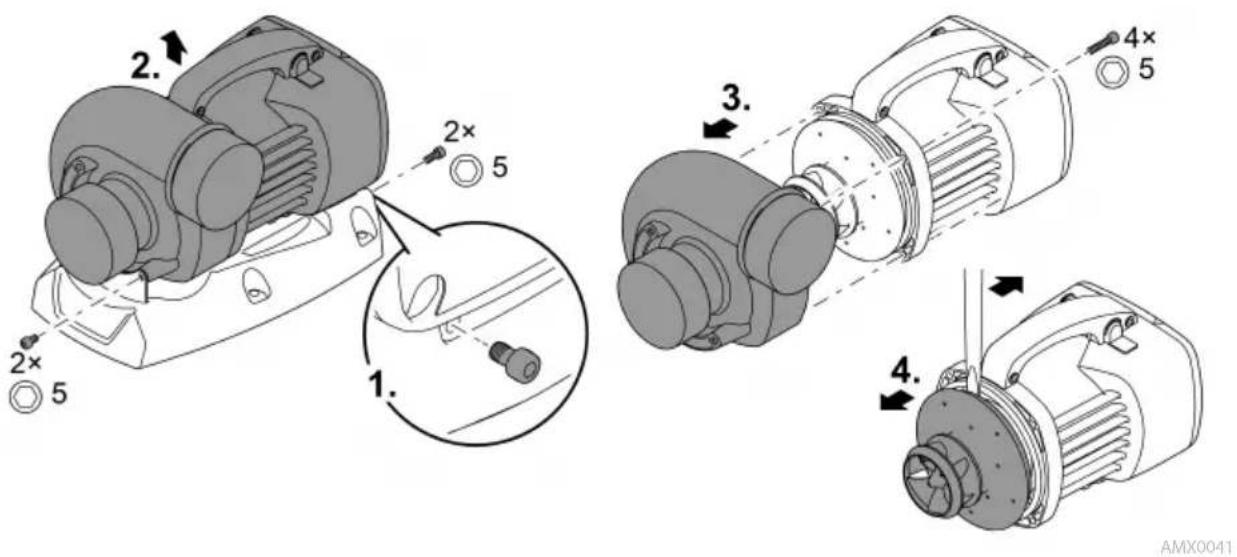
NOTE
If the pump housing jams when it is removed and pushes against the impeller unit, this will damage the impeller unit.
▶ Position the pump vertically before removing the pump housing. This ensures that the weight of the pump housing can no longer push against the impeller unit.
▶ Carefully pull the motor block off the pump housing, ensuring that it is kept straight.
▶ Proceed equally carefully during assembly.
- Remove the pipes on the suction side and on the pressure side.
- Use a wide-blade screwdriver to carefully lever out the impeller unit if necessary.
- After removing the impeller unit, clean all parts under running tap water.
- Replace a worn or damaged impeller unit.
- Assemble the pump in the reverse order.
- Tightening torque for all loosened screws: 3 Nm.
AquaMax Eco Titanium 31000
AquaMax Eco Titanium 51000
AquaMax Eco Titanium 81000

AMX0102
Storage/winter protection
The unit is not frost-proof and has to be removed and put into storage if minus temperatures are expected.
How to correctly store the unit:
• Thoroughly clean the unit.
- Check the unit for damage and replace damaged components.
- Store the pump submerged and in a frost-free environment.
- Protect open plug connections from moisture and dirt.
Malfunction remedy
| Malfunction | Possible cause | Remedy |
| Pump does not start | No mains voltage | Check the mains voltage.Check supply lines.Switch on the pump. |
| Pump does not transport fluid | Excessively soiled water | Clean the pump. The pump automatically switches on again once the motor has cooled down. |
| The impeller unit is blocked | Disconnect the power supply and remove obstacle. Then switch the pump on again. | |
| Insufficient delivered quantity | Impeller unit is running sluggishly | Clean the impeller unit |
| Excessive loss in the pipes due to friction | Select a larger pipe diameter.Reduce pipe length to the necessary minimum.Avoid unnecessary bends and connection elements. | |
| Pump switches off after operating briefly | Excessively soiled water | Clean the pump. The pump automatically switches on again once the motor has cooled down. |
| Water temperature too high | Note maximum water temperature of +35°C. The pump automatically switches on again once the motor has cooled down. | |
| Ambient temperature too high | Adhere to the maximum permissible ambient temperature. The pump automatically switches on again once the motor has cooled down. | |
| The impeller unit is blocked | Disconnect the power supply and remove obstacle. Then switch the pump on again. | |
| Pump has run dry. | Flood the pump. Fully submerge the pump for operation in the pond. |
EN
Technical data
Unit data
| Description | AquaMax Eco Titanium | ||||
| 31000 | 51000 | 81000 | |||
| Connection voltage | V AC | 220 ... 240 | 220 ... 240 | 220 ... 240 | |
| Mains frequency | Hz | 50/60 | 50/60 | 50/60 | |
| Power consumption | W | 35 ... 170 | 70 ... 320 | 100 ... 730 | |
| Control using | EGC | EGC | EGC | ||
| Inlet | Connection thread | G2 12 | G3 | G3 | |
| for pipe | DN63 | DN75 | DN75 | ||
| Outlet | Connection thread | G2 12 | G3 | G3 | |
| for pipe | DN63 | DN75 | DN75 | ||
| Permissible water temperature range (immersed installation) | °C | +4 ... +35 | +4 ... +35 | +4 ... +35 | |
| Max. permissible ambient temperature with natu-ral convection (dry installation) | °C | +30 | +30 | +30 | |
| Max. permissible ambient temperature with forced cooling (dry installation) | °C | +40 | +40 | +40 | |
| Max. pump capacity | l/h | 31500 | 51000 | 81000 | |
| Max. pump head | m | 3.3 | 4 | 5.5 | |
| Max. particle size, coarse dirt particles | mm | 6 | 6 | 6 | |
| Max. immersion depth | m | ≤4 | ≤4 | ≤4 | |
| Cable length | m | 10 | 10 | 10 | |
| Dimensions | Length | mm | 275 | 350 | 390 |
| Width | mm | 175 | 220 | 235 | |
| Height | mm | 200 | 245 | 245 | |
| Weight | kg | 9.2 | 16.5 | 17.5 | |
Permissible water quality
| Type | Fresh water | Pool water | Salt water | |
| pH value | 6.8 ... 8.5 | 7.2 ... 8.3 | 7.5 ... 8.5 | |
| Hardness | DH | 8 ... 15 | 8 ... 15 | 20 ... 30 |
| Free chlorine | mg/l | <0.3 | <0.6 | <0.3 |
| Chloride content | mg/l | <250 | <250 | <22000 |
| Salt content | % | <0.4 | <0.4 | <4 |
| Overall dry residue | mg/l | <50 | <50 | <50 |
| Temperature | °C | +4 ... +35 | +4 ... +30 | +4 ... +28 |
Wear parts
- Impeller unit
- Bearing in the motor block
EN
Disposal
NOTE
Do not dispose of this unit with household waste.
▶ Dispose of the unit by using the return system provided for this purpose.
▶ Should you have questions, please contact your local disposal company. They will give you information on how to correctly dispose of the unit.
▶ Render the unit unusable by cutting the cables.

AVERTISSEMENT
AquaMax Eco Titanium 81000
AquaMax Eco Titanium 81000

AquaMax Eco Titanium
AMX0052
AquaMax Eco Titanium 51000

AquaMax Eco Titanium 81000

AMX0042
AquaMax Eco Titanium 31000

AMX0051
AquaMax Eco Titanium 51000

AquaMax Eco Titanium 81000

Mise en service
REMARQUE
Environmental Function Control (EFC)
AquaMax Eco Titanium 51000

AquaMax Eco Titanium 81000

FR
AMX0102
AquaMax Eco Titanium 81000
AquaMax Eco Titanium 81000

AquaMax Eco Titanium
AMX0052
AquaMax Eco Titanium 51000

AquaMax Eco Titanium 81000
AMX0100
AMX0042
AquaMax Eco Titanium 31000

AMX0051
AquaMax Eco Titanium 51000

AquaMax Eco Titanium 81000

Ingebruikname
OPMERKING
Environmental Function Control (EFC)
AquaMax Eco Titanium 51000

AquaMax Eco Titanium 81000

AMX0102
Opslag/overwinteren
AquaMax Eco Titanium 81000
AquaMax Eco Titanium 81000

AMX0049
AMX0038
AMX0104
AquaMax Eco Titanium
AMX0052
AquaMax Eco Titanium 51000

ES
AquaMax Eco Titanium 81000

AMX0100
Garden Controller Home/Cloud
AMX0042
AquaMax Eco Titanium 31000
AquaMax Eco Titanium 51000

AquaMax Eco Titanium 81000

Puesta en marcha
INDICACIÓN
Environmental Function Control (EFC)
AquaMax Eco Titanium 51000

AquaMax Eco Titanium 81000

ES
AMX0102
AquaMax Eco Titanium 81000
AquaMax Eco Titanium 81000

AquaMax Eco Titanium
AMX0052
AquaMax Eco Titanium 51000
AquaMax Eco Titanium 81000
AMX0100
Garden Controller Home/Cloud
AMX0042
AquaMax Eco Titanium 31000

AMX0051
AquaMax Eco Titanium 51000
PT
AquaMax Eco Titanium 81000

Environmental Function Control (EFC)
PT
AquaMax Eco Titanium 51000
AquaMax Eco Titanium 81000

AMX0102
Armazenar/Invernar
AquaMax Eco Titanium 81000
AquaMax Eco Titanium 81000

AquaMax Eco Titanium
AMX0052
AquaMax Eco Titanium 51000

AquaMax Eco Titanium 81000

Garden Controller Home/Cloud
AMX0042
AquaMax Eco Titanium 31000

AMX0051
AquaMax Eco Titanium 51000

AquaMax Eco Titanium 81000

Messa in funzione
NOTA
Environmental Function Control (EFC)
AquaMax Eco Titanium 51000

AquaMax Eco Titanium 81000

AMX0102
AquaMax Eco Titanium 81000
AquaMax Eco Titanium 81000

AquaMax Eco Titanium
AMX0100
Garden Controller Home/Cloud
Der kan styres op til 10 OASE Control-kompatible apparater (pumper, filter, lamper) via appen "OASE Control".
Du kan finde oplysninger herom på www.oase.com under emnet "Smart havestyring og belysning".

flowchart
graph LR
    A["InScenio FM-Master"] -->|OC OUT| B["..."]
    C["GC"] --> D["IN OUT"]
    E["Garden Controller"] --> F["IN OUT"]
    G["OC Device 1"] --> H["IN OUT"]
    I["OC Device 2"] --> J["IN OUT"]
    K["OC Device n (≤10)"] --> L["IN OUT"]
    M["R"] --> N["OUT"]
    B -->|max. 100 m| N
    F -->|max. 100 m| N
    J -->|max. 100 m| N
    L -->|max. 100 m| N
AMX0042
AquaMax Eco Titanium 31000

AMX0051
AquaMax Eco Titanium 51000
AquaMax Eco Titanium 81000
Ibrugtagning
BEMÆRK
Environmental Function Control (EFC)
AMX0053
DA
AquaMax Eco Titanium 51000
AMX0041
AquaMax Eco Titanium 81000

AMX0102
Opbevaring/overvintring
AquaMax Eco Titanium 81000
AquaMax Eco Titanium 81000

AMX0049
AMX0038
AMX0104
AquaMax Eco Titanium
| 31000 | 51000 | 81000 | Beskrivelse | ||
| 1 | • | • | • | PumpehusPumpehuset kan dreies 90°. | |
| 2 | • | • | • | FotGaranterer at den står stødig, og det er mulig å skru den fast i underlaget. | |
| 3 | • | • | • | Utgang(trykkstuss) | Oppbevar beskyttelseskappen.Sett på beskyttelseskappen umiddelbart for å beskytte mot alvorlige skader når pumpen er i gang, dersom du har fjernet et tilkoblet rør. |
| 4 | • | • | • | Inngang(sugestuss) | |
| 5 | • | - | - | Klemmepåsats for feste av OASE Eco Control | |
| 6 | • | - | - | Gummistykke for klemmepåsats | |
| 7 - - | • | GummifotAvtagbar dersom foten skal skrus fast | |||
| 8 | • | • | • | Tilkobling styringFor betjening av pumpen trenger du styreenheten OASE Eco Control (tilbehør).Alternativt kan pumpen integreres i et OASE Control-nettverk.Informasjon om OASE Control finner du på www.oase.com. | |
AMX0052
AquaMax Eco Titanium 51000
AMX0043
AquaMax Eco Titanium 81000

AMX0100
AMX0042
AquaMax Eco Titanium 31000

AMX0051
AquaMax Eco Titanium 51000
AquaMax Eco Titanium 81000

Igangsetting
MERK
Environmental Function Control (EFC)
AquaMax Eco Titanium 51000

AquaMax Eco Titanium 81000

AMX0102
NO
Lagring/overvintring
Apparatet er ikke frostsikkert og må demonteres og lagres innendørs hvis man forventer frost. Slik lagrer du apparatet riktig:
AquaMax Eco Titanium 81000
AquaMax Eco Titanium 81000

AquaMax Eco Titanium
AquaMax Eco Titanium 51000

AquaMax Eco Titanium 81000

AMX0100
Garden Controller Home/Cloud
Upp till 10 st OASE Control-kompatibla apparater (pumpar, filter, lampor) kan styras med appen "OASE Control".
AMX0042
AquaMax Eco Titanium 31000

AMX0051
AquaMax Eco Titanium 51000

AquaMax Eco Titanium 81000

Driftstart
ANVISNING
Environmental Function Control (EFC)
AquaMax Eco Titanium 51000

AquaMax Eco Titanium 81000

AMX0102
AquaMax Eco Titanium 81000
AquaMax Eco Titanium 81000

AMX0049
AMX0038
AMX0104
AquaMax Eco Titanium
AMX0052
AquaMax Eco Titanium 51000

AquaMax Eco Titanium 81000

AMX0042
AquaMax Eco Titanium 31000
AMX0051
AquaMax Eco Titanium 51000

AquaMax Eco Titanium 81000

Käyttöönotto
OHJE
Environmental Function Control (EFC)
AquaMax Eco Titanium 51000

AquaMax Eco Titanium 81000

AMX0102
AquaMax Eco Titanium 81000
AquaMax Eco Titanium 81000

AquaMax Eco Titanium
AMX0052
AquaMax Eco Titanium 51000

AquaMax Eco Titanium 81000

AMX0100
AMX0042
AquaMax Eco Titanium 31000

AMX0051
AquaMax Eco Titanium 51000

AquaMax Eco Titanium 81000
Üzembe helyezés
TUDNIVALÓ:
Environmental Function Control (EFC)
AquaMax Eco Titanium 51000

AquaMax Eco Titanium 81000

AMX0102
Tárolás/Telelés
AquaMax Eco Titanium 81000
AquaMax Eco Titanium 81000

AMX0049
AMX0038
AMX0104
AquaMax Eco Titanium
AMX0052
AquaMax Eco Titanium 51000

AquaMax Eco Titanium 81000

AMX0042
AquaMax Eco Titanium 31000

AquaMax Eco Titanium 51000

AquaMax Eco Titanium 81000

Rozruch
WSKAZÓWKA
Environmental Function Control (EFC)
AquaMax Eco Titanium 51000

AquaMax Eco Titanium 81000

AMX0102
AquaMax Eco Titanium 81000
AquaMax Eco Titanium 81000

AquaMax Eco Titanium
AMX0052
AquaMax Eco Titanium 51000

AquaMax Eco Titanium 81000

AMX0100
Připojení řízení
Garden Controller Home/Cloud
AMX0042
AquaMax Eco Titanium 31000

AMX0051
AquaMax Eco Titanium 51000

AquaMax Eco Titanium 81000

Uvedení do provozu
UPOZORNĚNÍ
Environmental Function Control (EFC)
AquaMax Eco Titanium 51000

AquaMax Eco Titanium 81000

AMX0102
Uložení/zazimování
AMX0038
AquaMax Eco Titanium 81000
AquaMax Eco Titanium 81000

AMX0104
AquaMax Eco Titanium
| 31000 | 51000 | 81000 | Opis | ||
| 1 | • | • | • | Teleso čerpadlaTeleso čerpadla možno otočit o 90°. | |
| 2 | • | • | • | Podstavec zariadeniaZaručuje bezpečnú polohu, zaskrutkovanie na podklade je možné. | |
| 3 | • | • | • | Výstup(tlakové hrdlo) | Uschovajte ochranné veko.Ochranné veko ihned' osad'te na ochranu pred tažkými poraneniami pri bežiacom čer-padle, ak ste odstránili pripojenúrúru. |
| 4 | • | • | • | Vstup(sacie hrdlo) | |
| 5 | • | -- | Svorkový nadstavec na upevnenie OASE Eco Control | ||
| 6 | • | - | - | Gumový diel pre svorkový nadstavec | |
| 7 -- | • | Gumová pätkaSnímatelná, ak sa má zaskrutkovať pätka zariadenia | |||
| 8 | • | • | • | Prípojka riadenia | |
AMX0052
AquaMax Eco Titanium 51000

AquaMax Eco Titanium 81000
Pripojenie riadenia
AMX0042
AquaMax Eco Titanium 31000
AMX0051
AquaMax Eco Titanium 51000
AquaMax Eco Titanium 81000

Environmental Function Control (EFC)
AquaMax Eco Titanium 51000

AquaMax Eco Titanium 81000

AMX0102
Uloženie/prezimovanie
AquaMax Eco Titanium 81000
AquaMax Eco Titanium 81000
AquaMax Eco Titanium
AMX0100
Povezovanje krmiljenja
AMX0042
AquaMax Eco Titanium 31000
AMX0051
AquaMax Eco Titanium 51000

AquaMax Eco Titanium 81000

Zagon
NASVET
Environmental Function Control (EFC)
AquaMax Eco Titanium 51000
AquaMax Eco Titanium 81000

AMX0102
AquaMax Eco Titanium 81000
AquaMax Eco Titanium 81000

AMX0049
AMX0038
AMX0104
AquaMax Eco Titanium
| 31000 | 51000 | 81000 | Opis | ||
| 1 | ● | ● | ● | Kućište pumpeKućište pumpe moguće je okrenuti za 90°. | |
| 2 | ● | ● | ● | Noga uređajaOsigurava siguran položaj, moguće je pričvršćivanje za podlogu. | |
| 3 | ● | ● | ● | Izlaz(tlačni nastavak) | Sačuvajte zaštitne kapice.Radi zaštite od teških ozljeda kada pumpa radi odmah postavite zaštitnu kapicu ako ste demontirali priključenu cijev. |
| 4 | ● | ● | ● | Ulaz(usisni nastavak) | |
| 5 | ● | -- | Nastavak stezaljke za pričvršćivanje OASE Eco Control | ||
| 6 | ● | - | - | Gumeni element za nastavak stezaljke | |
| 7 -- | ● | Gumeno stopaloOdvojivo ako je potrebno pričvrstiti nogu uređaja | |||
| 8 | ● | ● | ● | Priključak upravljačaZa upravljanje pumpom potreban je upravljački uređaj OASE Eco Control (dodaci).Umjesto toga, pumpa se može priključiti na OASE Control-mrežu.Informacije za OASE Control možete pronaći na www.oase.com. | |
Simboli na uređaju
IP68

Uređaj je nepropustan za prašinu i vodu do 4 m.

AMX0100
AMX0042
AquaMax Eco Titanium 31000

AMX0051
AquaMax Eco Titanium 51000

AquaMax Eco Titanium 81000

Stavljanje u pogon
NAPOMENA
Environmental Function Control (EFC)
Pumpa prilikom stavljanja u pogon, a zatim tijekom rada svakih 20 ... 40 minuta automatski obavlja unaprijed programiranu samoprovjeru (Environmental Function Control (EFC)). Pumpa prepoznaje radi li pritom na suho, je li blokirana ili uronjena. U slučaju rada na suho ili blokiranja, pumpa se automatski isključuje nakon otprilike 60 do 120 sekundi. U slučaju neispravnosti prekinite dovod elektroenergije i „potopite pumpu“ ili uklonite prepreku. Nakon toga možete uređaj ponovno staviti u pogon.
AquaMax Eco Titanium 51000
AquaMax Eco Titanium 81000

AMX0102
AquaMax Eco Titanium 81000
AquaMax Eco Titanium 81000

AquaMax Eco Titanium
AMX0100
AMX0042
AquaMax Eco Titanium 31000

AMX0051
AquaMax Eco Titanium 51000

AquaMax Eco Titanium 81000

RO
Environmental Function Control (EFC)
AquaMax Eco Titanium 51000

RO
AquaMax Eco Titanium 81000

AMX0102
AMX0038
AquaMax Eco Titanium 81000
AquaMax Eco Titanium 81000

AquaMax Eco Titanium
AMX0052
AquaMax Eco Titanium 51000

AquaMax Eco Titanium 81000
AMX0100
Garden Controller Home/Cloud
AMX0042
AquaMax Eco Titanium 31000

AMX0051
AquaMax Eco Titanium 51000
AquaMax Eco Titanium 81000

Environmental Function Control (EFC)
AMX0053
AquaMax Eco Titanium 51000

AMX0041
AquaMax Eco Titanium 81000
AMX0102
AMX0038
AquaMax Eco Titanium 81000
AquaMax Eco Titanium 81000

AMX0104
AquaMax Eco Titanium
AMX0052
UK
AquaMax Eco Titanium 51000

AquaMax Eco Titanium 81000

AMX0100
Garden Controller Home/Cloud
AMX0042
AquaMax Eco Titanium 31000

AMX0051
AquaMax Eco Titanium 51000

AquaMax Eco Titanium 81000

UK
Environmental Function Control (EFC)
AquaMax Eco Titanium 51000
UK
AquaMax Eco Titanium 81000

AMX0102
AMX0038
AquaMax Eco Titanium 81000
AquaMax Eco Titanium 81000

AquaMax Eco Titanium
AMX0052
AquaMax Eco Titanium 51000

AquaMax Eco Titanium 81000
AMX0100
RU
Garden Controller Home/Cloud
AMX0042
AquaMax Eco Titanium 31000

AMX0051
RU
AquaMax Eco Titanium 51000

AquaMax Eco Titanium 81000

Пуск в эксплуатацию
УКАЗАНИЕ
Environmental Function Control (EFC)
AMX0053
AquaMax Eco Titanium 51000
AMX0041
AquaMax Eco Titanium 81000

AMX0102
AquaMax Eco Titanium 81000
AquaMax Eco Titanium 81000

AquaMax Eco Titanium
AMX0052
AquaMax Eco Titanium 51000

AquaMax Eco Titanium 81000
AMXO100
连接控制器
泵可以在有或没有控制系统的情况下运行。
AMX0042
AquaMax Eco Titanium 31000

AMX0051
AquaMax Eco Titanium 51000

AquaMax Eco Titanium 81000

调试
提示
Environmental Function Control (EFC)
AquaMax Eco Titanium 51000
AMX0102
存放/过冬
line
| Q [l/min] | P = 100 % | P = 90 % | P = 80 % | P = 70 % | P = 60 % | P = 50 % | P = 40 % | P = 30 % | P = 20 % | P = 10 % | P = 1 % | | --------- | --------- | -------- | -------- | -------- | -------- | -------- | -------- | -------- | -------- | -------- | ------- | | 0 | 180.0 | 160.0 | 140.0 | 120.0 | 100.0 | 80.0 | 60.0 | 40.0 | 20.0 | 10.0 | 40.0 | | 300 | 180.0 | 160.0 | 140.0 | 120.0 | 100.0 | 80.0 | 60.0 | 40.0 | 20.0 | 10.0 | 40.0 | | 525 | 150.0 | 140.0 | 130.0 | 120.0 | 110.0 | 90.0 | 75.0 | 65.0 | 55.0 | 45.0 | 35.0 |AMX0057
line
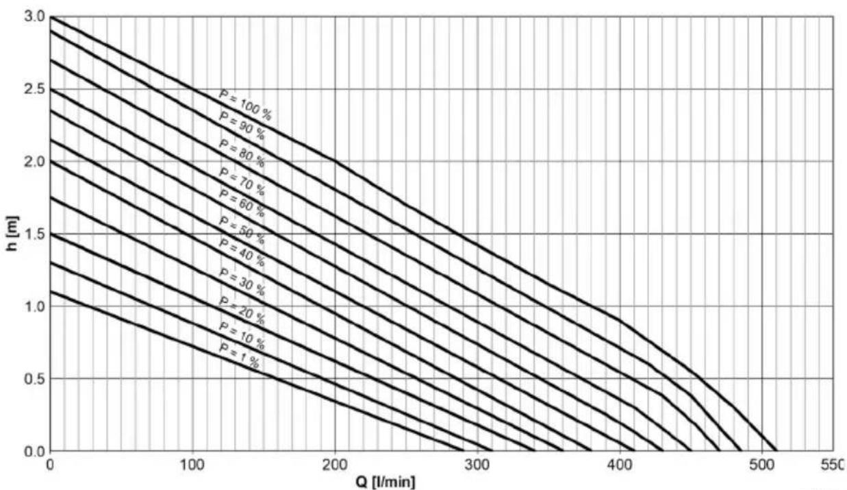
| Q [l/min] | P = 100 % | P = 90 % | P = 80 % | P = 70 % | P = 60 % | P = 50 % | P = 40 % | P = 30 % | P = 20 % | P = 10 % | P = 1 % | | --------- | --------- | -------- | -------- | -------- | -------- | -------- | -------- | -------- | -------- | -------- | ------- | | 0 | 3.0 | 2.8 | 2.6 | 2.4 | 2.2 | 2.0 | 1.8 | 1.6 | 1.4 | 1.2 | 1.0 | | 100 | 2.5 | 2.3 | 2.1 | 1.9 | 1.7 | 1.5 | 1.3 | 1.1 | 0.9 | 0.7 | 0.5 | | 200 | 2.0 | 1.8 | 1.6 | 1.4 | 1.2 | 1.0 | 0.8 | 0.6 | 0.4 | 0.2 | 0.0 | | 300 | 1.5 | 1.3 | 1.1 | 0.9 | 0.7 | 0.5 | 0.3 | 0.1 | -0.1 | -0.3 | -0.5 | | 400 | 1.0 | 0.8 | 0.6 | 0.4 | 0.2 | 0.0 | -0.2 | -0.4 | -0.6 | -0.8 | -1.0 | | 500 | 0.5 | 0.3 | 0.1 | -0.1 | -0.3 | -0.5 | -0.7 | -0.9 | -1.1 | -1.3 | -1.5 | | 550 | 0.0 | -0.2 | -0.4 | -0.6 | -0.8 | -1.0 | -1.2 | -1.4 | -1.6 | -1.8 | -2.0 |AMX0058
AquaMax Eco Titanium 51000
line
| P [%] | Q [l/min] | P [W] | |-------|-----------|-------| | 100 | 450 | 65 | | 90 | 450 | 80 | | 80 | 450 | 100 | | 70 | 450 | 120 | | 60 | 450 | 140 | | 50 | 450 | 160 | | 40 | 450 | 180 | | 30 | 450 | 200 | | 20 | 450 | 220 | | 10 | 450 | 240 | | 1 | 450 | 260 |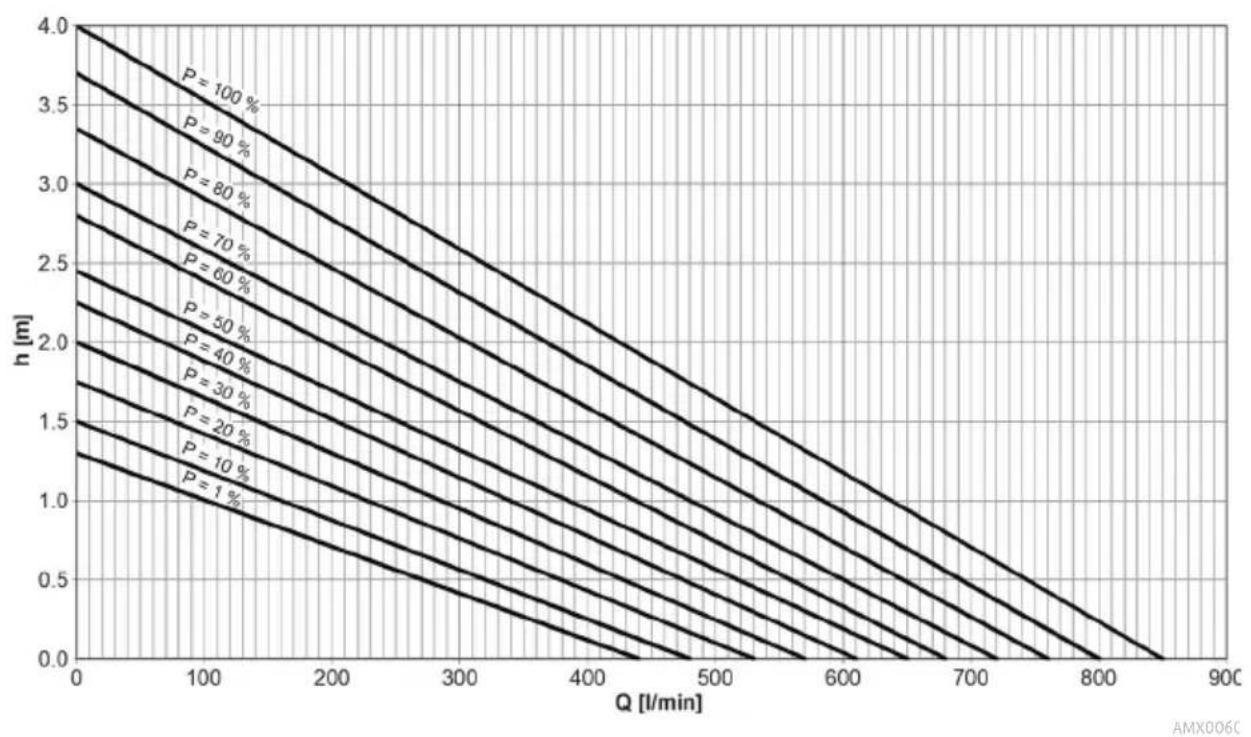
line
| Q [l/min] | P = 100 % | P = 90 % | P = 80 % | P = 70 % | P = 60 % | P = 50 % | P = 40 % | P = 30 % | P = 20 % | P = 10 % | | --------- | --------- | -------- | -------- | -------- | -------- | -------- | -------- | -------- | -------- | -------- | | 0 | 4.0 | 3.7 | 3.4 | 3.1 | 2.8 | 2.5 | 2.2 | 1.9 | 1.6 | 1.3 | | 100 | 3.5 | 3.1 | 2.8 | 2.5 | 2.2 | 1.9 | 1.6 | 1.3 | 1.0 | 0.7 | | 200 | 3.0 | 2.6 | 2.3 | 2.0 | 1.7 | 1.4 | 1.1 | 0.8 | 0.5 | 0.3 | | 300 | 2.5 | 2.1 | 1.8 | 1.5 | 1.2 | 0.9 | 0.6 | 0.3 | 0.1 | -0.1 | | 400 | 2.0 | 1.6 | 1.3 | 1.0 | 0.7 | 0.4 | 0.1 | -0.1 | -0.3 | -0.5 | | 500 | 1.5 | 1.1 | 0.8 | 0.5 | 0.2 | -0.1 | -0.3 | -0.5 | -0.7 | -0.9 | | 600 | 1.0 | 0.6 | 0.3 | 0.1 | -0.1 | -0.3 | -0.5 | -0.7 | -0.9 | -1.1 | | 700 | 0.5 | 0.2 | -0.1 | -0.3 | -0.5 | -0.7 | -0.9 | -1.1 | -1.3 | -1.5 | | 800 | 0.1 | -0.1 | -0.3 | -0.5 | -0.7 | -0.9 | -1.1 | -1.3 | -1.5 | -1.7 | | 900 | -0.3 | -0.5 | -0.7 | -0.9 | -1.1 | -1.3 | -1.5 | -1.7 | -1.9 | -2.1 |AquaMax Eco Titanium 81000
line
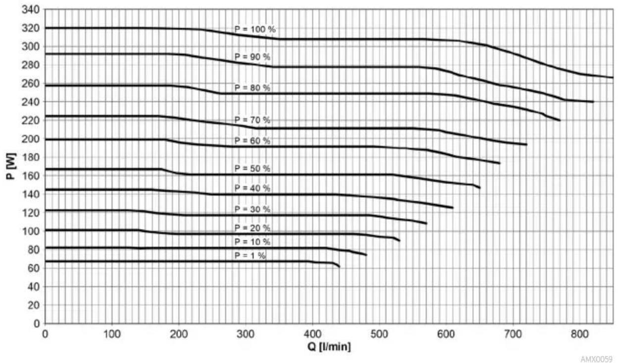
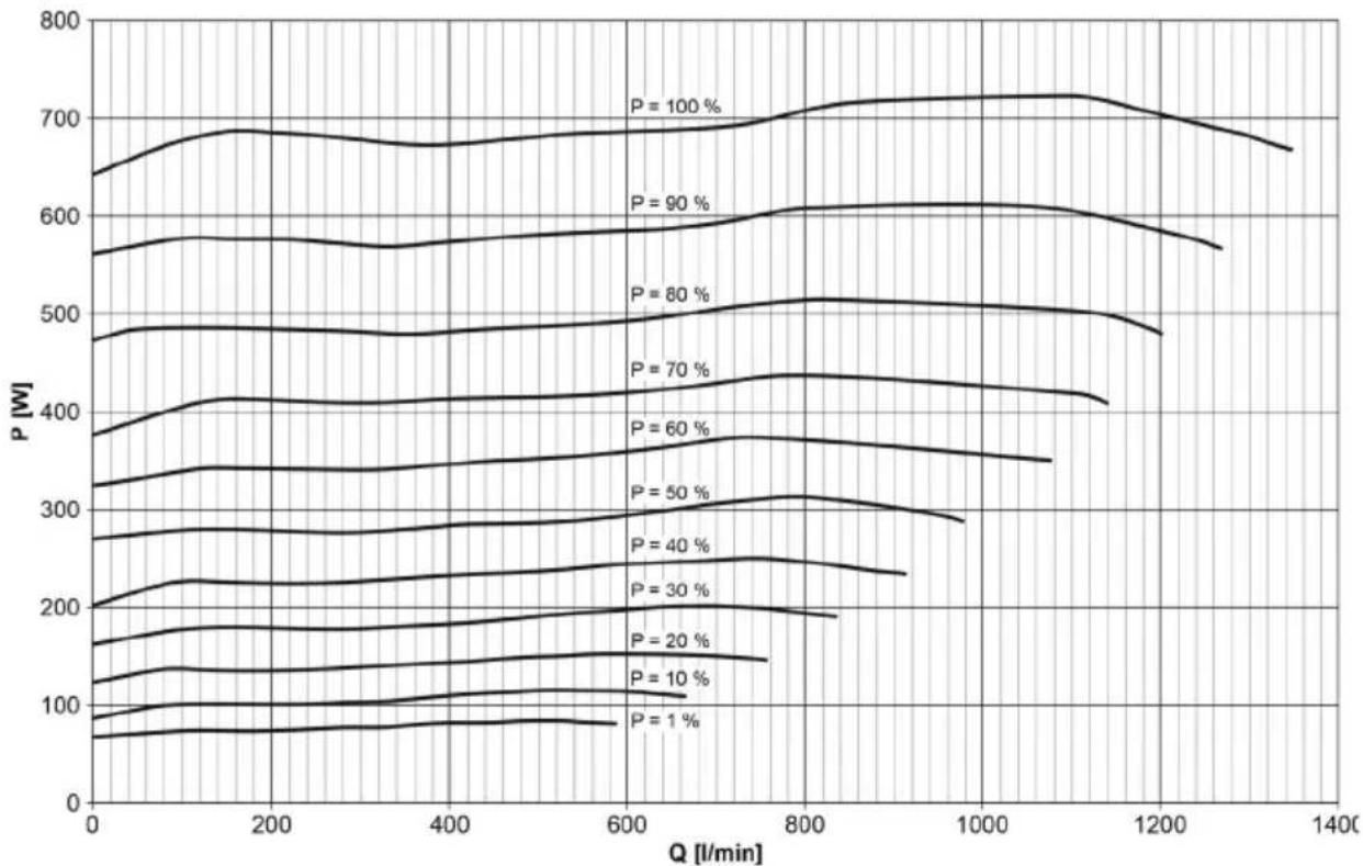
| Q [l/min] | P = 100 % | P = 90 % | P = 80 % | P = 70 % | P = 60 % | P = 50 % | P = 40 % | P = 30 % | P = 20 % | P = 10 % | P = 1 % | | --------- | --------- | -------- | -------- | -------- | -------- | -------- | -------- | -------- | -------- | -------- | ------- | | 0 | 650 | 570 | 480 | 410 | 340 | 270 | 200 | 160 | 120 | 80 | 60 | | 200 | 690 | 580 | 490 | 420 | 350 | 280 | 210 | 170 | 130 | 90 | 70 | | 400 | 680 | 575 | 485 | 415 | 345 | 275 | 205 | 165 | 125 | 85 | 75 | | 600 | 685 | 585 | 495 | 425 | 355 | 285 | 215 | 175 | 135 | 90 | 80 | | 800 | 710 | 610 | 510 | 440 | 370 | 300 | 230 | 190 | 145 | 100 | 85 | | 1000 | 720 | 620 | 520 | 450 | 380 | 310 | 240 | 200 | 155 | 110 | 95 | | 1200 | 700 | 590 | 500 | 430 | 360 | 290 | 220 | 185 | 140 | 105 | 90 | | 1400 | 670 | 560 | 480 | 410 | 340 | 270 | 210 | 175 | 135 | 115 | 85 |AMX0111
line
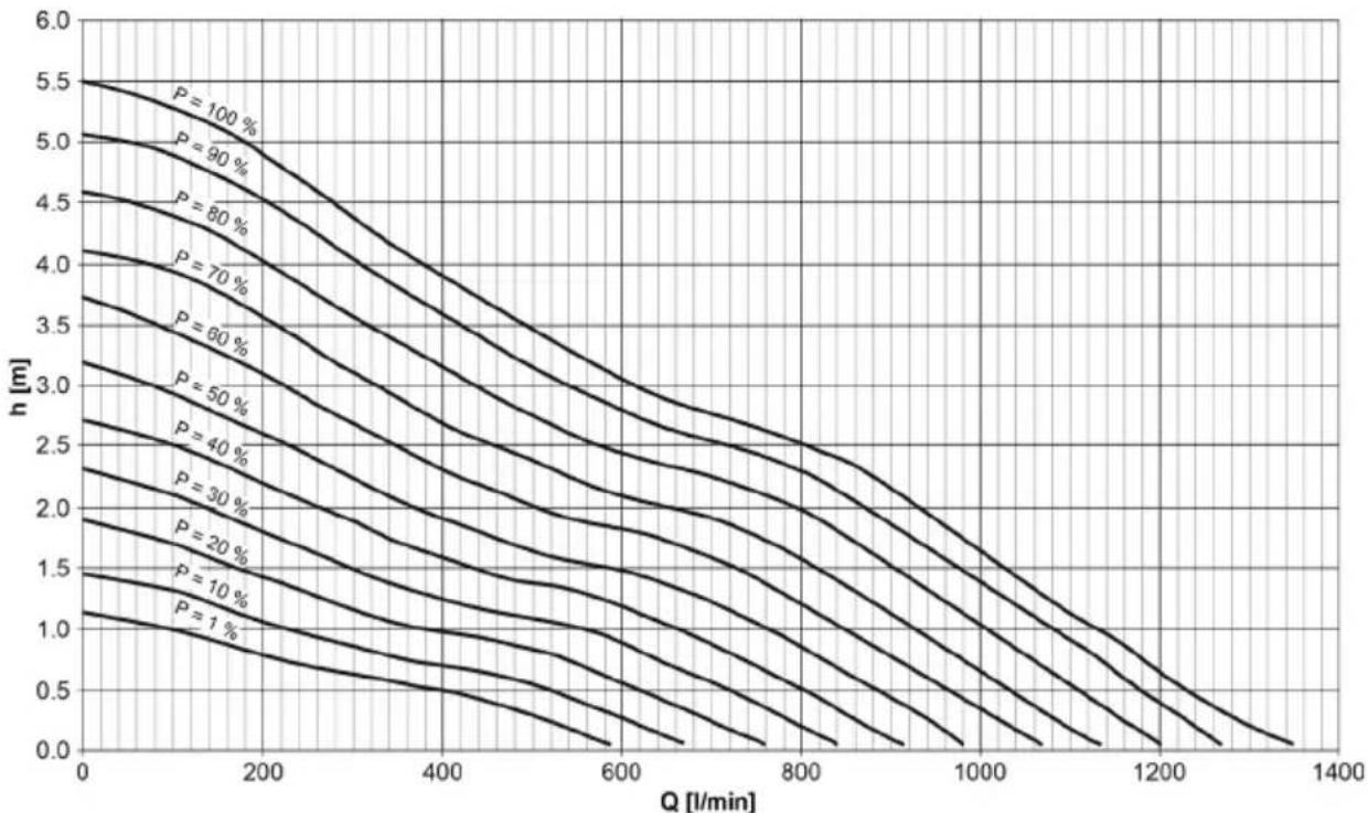
| Q [l/min] | P = 100 % | P = 90 % | P = 80 % | P = 70 % | P = 60 % | P = 50 % | P = 40 % | P = 30 % | P = 20 % | P = 10 % | | --------- | --------- | -------- | -------- | -------- | -------- | -------- | -------- | -------- | -------- | -------- | | 0 | 5.5 | 5.0 | 4.5 | 4.0 | 3.5 | 3.0 | 2.5 | 2.0 | 1.5 | 1.0 | | 200 | 5.0 | 4.5 | 4.0 | 3.5 | 3.0 | 2.5 | 2.0 | 1.5 | 1.0 | 0.5 | | 400 | 4.5 | 4.0 | 3.5 | 3.0 | 2.5 | 2.0 | 1.5 | 1.0 | 0.5 | 0.25 | | 600 | 4.0 | 3.5 | 3.0 | 2.5 | 2.0 | 1.5 | 1.0 | 0.5 | 0.25 | 0.1 | | 800 | 3.5 | 3.0 | 2.5 | 2.0 | 1.5 | 1.0 | 0.5 | 0.25 | 0.1 | 0.05 | | 1000 | 3.0 | 2.5 | 2.0 | 1.5 | 1.0 | 0.5 | 0.25 | 0.1 | 0.05 | 0.025 | | 1200 | 2.5 | 2.0 | 1.5 | 1.0 | 0.5 | 0.25 | 0.1 | 0.05 | 0.025 | 0.01 | | 1400 | 2.0 | 1.5 | 1.0 | 0.5 | 0.25 | 0.1 | 0.05 | 0.025 | 0.01 | 0.005 |AMX0112
| Pos. | AquaMax EcoTitanium 31000 |
| 1 | 40509 |
| 2 | 15591 |
| 3 | 46962 |
| 4 | 48597 |
| 5 | 46952 |
| 6 | 48673 |
| 7 | 17513 |
| 8 | 17232 |
| 9 | 46950 |
AMX009
| Pos. | AquaMax EcoTitanium 51000 |
| 1 | 43863 |
| 2 | 40509 |
| 3 | 43864 |
| 4 | 42061 |
| 5 | 42094 |
| 6 | 73658 |
| 7 | 41405 |
| 8 | 43865 |
| 9 | 15574 |

AMX009E
AMX0103

- AquaMax Eco Titanium
- HINWEIS
- Environmental Function Control (EFC)
- Lagern/Überwintern
- Safety information
- Electrical connection
- Safe operation
- Intended use
- Product Description
- Overview
- Symbols on the unit
- Seasonal Flow Control (SFC)
- Installation and connection
- WARNING
- Turning the pump casing to achieve a different position
- NOTE
- Connecting the control system
- Submerged installation of the pump
- Dry installation of the pump
- Connecting the pressure side/suction side
- Commissioning/start-up
- Switching ON/OFF
- Maintenance and cleaning
- CAUTION
- Cleaning the device
- Cleaning/replacing the impeller unit
- AquaMax Eco Titanium 81000
- Storage/winter protection
- Technical data
- Unit data
- Wear parts
- Disposal
- AVERTISSEMENT
- Mise en service
- REMARQUE
- Ingebruikname
- OPMERKING
- Opslag/overwinteren
- Puesta en marcha
- INDICACIÓN
- Armazenar/Invernar
- Messa in funzione
- NOTA
- Ibrugtagning
- BEMÆRK
- Opbevaring/overvintring
- Igangsetting
- MERK
- Lagring/overvintring
- Driftstart
- ANVISNING
- Käyttöönotto
- OHJE
- Üzembe helyezés
- TUDNIVALÓ:
- Tárolás/Telelés
- Rozruch
- WSKAZÓWKA
- Připojení řízení
- Uvedení do provozu
- UPOZORNĚNÍ
- Uložení/zazimování
- Pripojenie riadenia
- Uloženie/prezimovanie
- Povezovanje krmiljenja
- Zagon
- NASVET
- Simboli na uređaju
- Stavljanje u pogon
- NAPOMENA
- Пуск в эксплуатацию
- УКАЗАНИЕ
- 连接控制器
- 调试
- 提示
- 存放/过冬
Brand : OASE
Model : AquaMax Eco Titanium 31000
Category : Water pump