Vario Program R350 - Rowing Machine BH FITNESS - Free user manual and instructions
Find the device manual for free Vario Program R350 BH FITNESS in PDF.
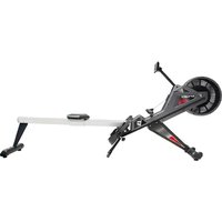
| Product Type | Rowing Machine |
| Brand | BH Fitness |
| Model | Vario Program R350 |
| Usage | Home |
| Standard | EN957 class H.C. |
| Maximum User Weight | 136 kg |
| Power Supply | Transformer 6V - 1A (220V) |
| Meter | Electronic stroke counter |
| Seat Adjustment | Yes, by rack and locking knob |
| Folding | Yes, with safety pin and knob |
| Footrests | Adjustable with fixing straps |
| Transport Wheels | Yes, at the front |
| Floor Surface | Requires a protection mat |
| Maintenance | Storage in a dry place, cleaning with a dry cloth |
| Spare Parts | Available on order from the manufacturer |
Frequently Asked Questions - Vario Program R350 BH FITNESS
User questions about Vario Program R350 BH FITNESS
0 question about this device. Answer the ones you know or ask your own.
Ask a new question about this device
Download the instructions for your Rowing Machine in PDF format for free! Find your manual Vario Program R350 - BH FITNESS and take your electronic device back in hand. On this page are published all the documents necessary for the use of your device. Vario Program R350 by BH FITNESS.
USER MANUAL Vario Program R350 BH FITNESS
natural_image
Exterior view of a white stationary rower machine (no visible text or symbols)Instrucciones de montaje y utilización Instructions for assembly and use Instructions de montage et utilisation Montage und Gebrauchsanleitung Instruções de montagem e utilização Istruzioni di montaggio e uso Montage-en gebruiksinstrukties
Fig.0
text_image
Technical diagram showing exploded view of mechanical components with numbered parts and labeled partsFig.1
text_image
1 2 89 81 RFig.2
text_image
L 94 97 46L 78 116 94 M 48 116 78 44 R 46R 97 94Fig.3
text_image
Technical diagram of a mechanical device with numbered components and labeled partsFig.4
text_image
52 60 79 1 97 59Fig.5
text_image
Fig E 64 67 Fig F 68 64 95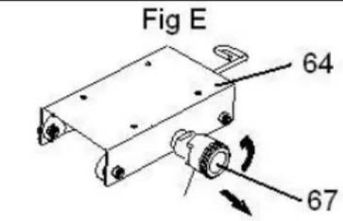
text_image
Fig E 64 67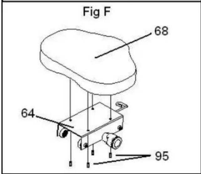
text_image
Fig F 68 64 95Fig.6
text_image
68 67 79 102 52 N 105 79 63 62Fig.7
text_image
54 55 52 53 63 59Fig.8
text_image
1 2 43 62 74 75 74Fig.9
text_image
Fig G 1 52 68 59 63 62 Fig H 52 59Fig.10
text_image
Fig J 52 1 59 Fig K 52 62 63Fig.11
natural_image
Line drawing of a person pushing a mechanical device with a numbered label (77), no text or symbols present.Fig.12
text_image
1 119 m n 220 vEspañol
Consult your doctor before starting any exercise program. It is advisable to undergo a complete physical examination.
Work at the recommended exercise level, do not overexert yourself. If you feel any pain or discomfort, stop exercising immediately and consult your doctor.
Use the appliance on a solid, flat surface, with some type of protection for the floor or carpet.
GENERAL INSTRUCTIONS.-
Carefully read through the instructions contained in this manual. It provides you with important information about assembly, safety and use of the machine.
1 This appliance has been tested and it complies with standard EN957 under class H.C., suitable for domestic use only. Maximum user weight 136 kg.
2 Keep your hands well away from any of the moving parts.
3 It can only be used by one person at a time.
4 If you experience dizziness, nausea, chest pains or any other symptom while using this appliance STOP the exercise. SEEK MEDICAL ATTENTION IMMEDIATELY
5 Use the appliance on a level, solid surface. DO NOT use the bicycle outdoors or close to water.
6 Parents and/or those responsible for children should always take their curious nature into account and how this can often lead to hazardous situations and behaviour resulting in accidents. Under no circumstances should this appliance be used as a toy.
7 Your unit can only be used by one person at a time.
8 Use suitable clothing and footwear. Make sure all laces/cords are tied correctly.
9 This appliance must only be used for the purposes described in this manual. DO NOT use accessories that are not recommended by the manufacturer.
10 Do not place sharp objects near the machine.
11 Disabled people should not use the machine without the assistance of a qualified person or a doctor.
12 Do warm up stretching exercises before using the equipment.
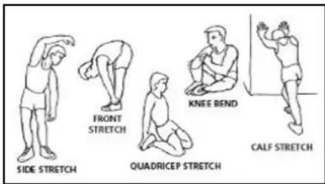
EXERCISE INSTRUCTIONS.-Warm-up phase
This phase speeds up the body's blood circulation and gets the muscles ready for exercise. It also reduces the risk of cramp and sprains.
It is advisable to do some stretching exercises, as shown below.
text_image
SIDE STRETCH FRONT STRETCH QUADRICEP STRETCH KNEE BEND CALF STRETCHEach stretch should last approximately 30 seconds, do not overexert the muscles. If you feel pain, STOP.
Keep these instructions safe for future use.
1. ASSEMBLY INSTRUCTIONS.-
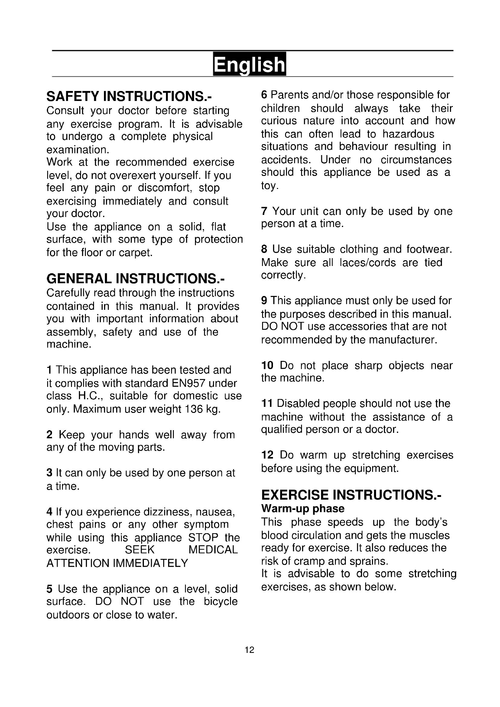
Take the unit out of its box and make sure that all of the pieces are there Fig.0: The assistance of a second person is recommended when assembling this unit.
(1) Main body.
(44) Footrest rotation shaft.
(46) Right footrest.
(46) Left footrest.
(47) Pedal clip holding straps.
(48) Footrest support spindle.
(52) Seat rail.
(55) Rear support cover.
(60) Folded retaining support
(62) Rear rail support.
(64) Seat support.
(68) Seat
(116) Pull-up foot supports.
(119) Transformer 6v 1Amp.
(2) Front stabiliser bar with wheels.
NUTS & BOLTS.
(63) Lock pin
(78) Screw cap
(79) Nut cap.
(81) Allen screw M-8x70.
(89) Spring washer M8.
(94) Allen screw M-8x15.
(95) Allen screw M-6x15.
(97) Flat washer M8.
(109) Screw M-8x15.
Allen key 6 mm
Combination spanner.
Box spanner with star screw-driver
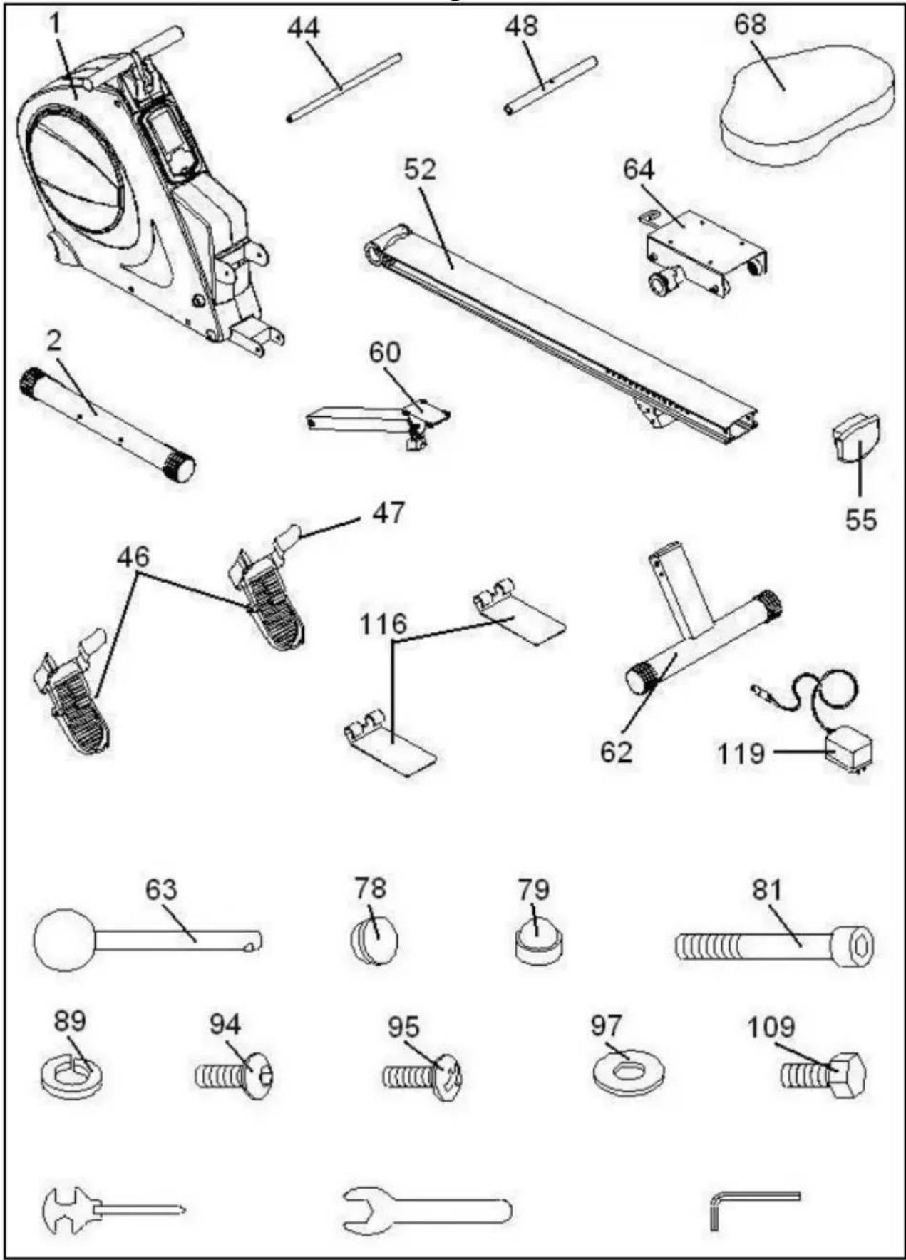
2. FITTING THE STABILISER BARS.-
Bring the front stabiliser bar with wheels (2) to the main body (1) positioning the wheels at the front of the unit, Fig.1, insert screws (81), fit the spring washers (89). Use the 6 mm Allen key to tighten securely.
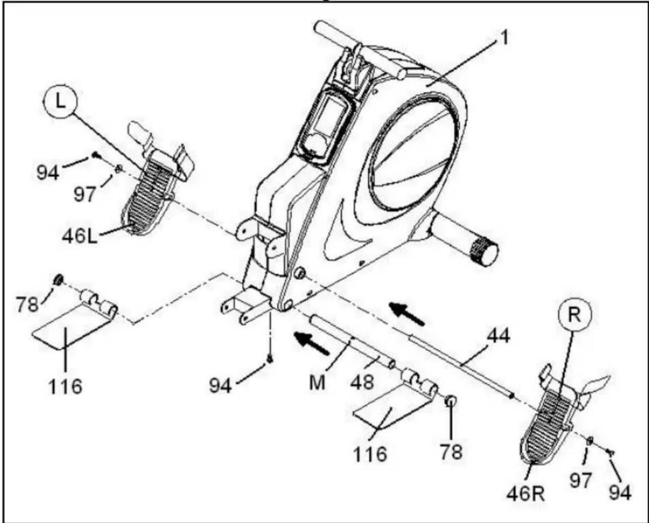
3. FITTING THE FOOTREST RETAINER SHAFT.-
Take the shortest shaft (48), insert it in through the hole at the bottom of the frame (1) and align it with the hole for the bolt (94).
Next insert the pull-up supports (116) into the ends of the tube you have just finished assembling and fit the screw caps (78).
4 FITTING THE FOOTRESTS.-
First insert the longest shaft (44) in through the hole on the frame, as shown in Fig.2, leaving it centred.
Next, take the left-hand footrest (46) and fit it onto the shaft (44), Fig.2 and then do the same with the right-hand footrest (46).
Take the flat washers (97) and the Screw (94) and tighten each end of the shaft using Allen key 6 mm.
Once you have fitted the footrests take the pedal straps (47) and attach them to the footrests.
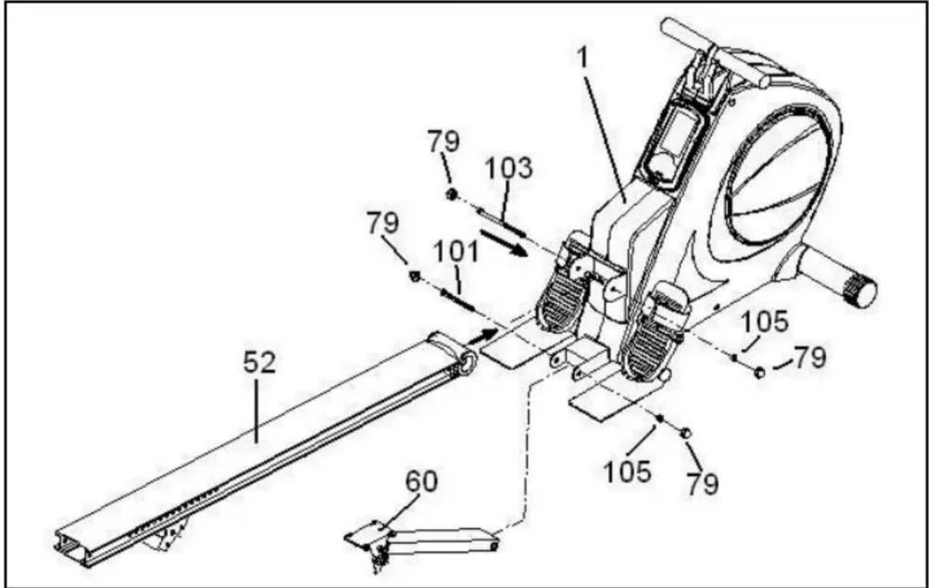
Insert the aluminium rail (52) onto the main body (1) in the direction of the arrow, Fig.3.
Fit the bolt (103) in the direction of the arrow, along with the nut (105) removed previously, Fig.3 and tighten. Fit the nut cap (79), Fig.3.
Remove the screw (101) along with the nut (105) from the "U" piece on the main body (1). Position the retaining bar support (60) on the "U" piece and tighten using screw (101) removed previously.
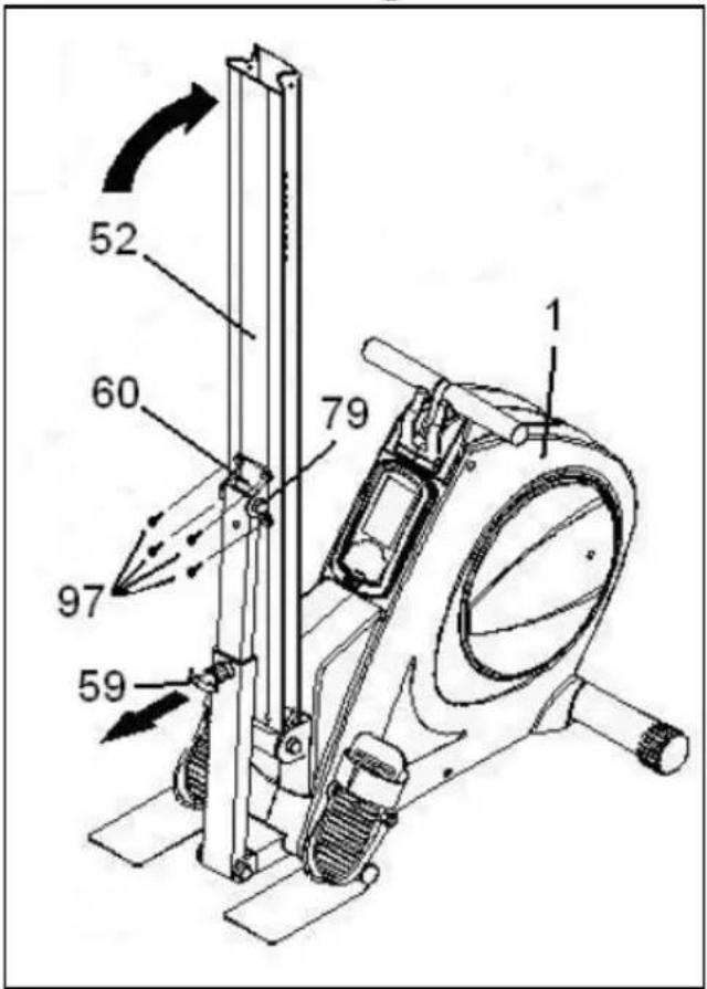
Lift the aluminium rail that you have just fitted as shown in Fig.4.
Pull the knob (59) back and lift the support so that the bolt holes line up, fit the bolts (97) and tighten securely.
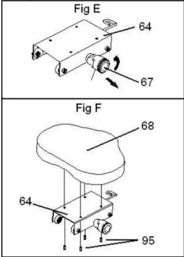
First, Fig.5, take the saddle support (64) and pull the knob (67) outward, Fig. E, twisting it so that it locks into position.
Position the saddle (68), Fig.5, on the saddle support (64), Fig.F, lining up the holes and secure using screws (95).
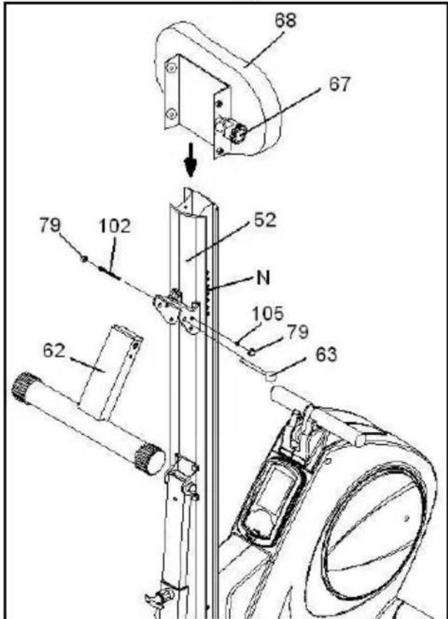
Remove the saddle stop (54), Fig.7, and once you have fitted the saddle insert it into the aluminium rail as shown in Fig.6, when it reaches the rack (N) turn the knob (67) and release it so that it slots into one of the openings on the rack, preventing the saddle from moving on the aluminium rail.
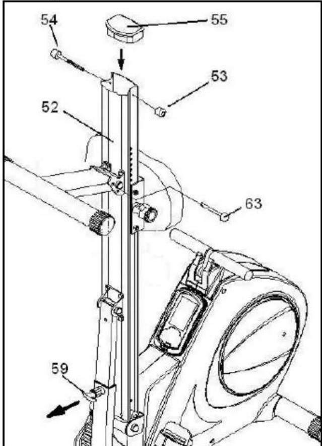
Fit the saddle stop screw (54) removed previously and fit the end cap (55), as shown in Fig.7.
Position the support (60) at the top of the rail, Fig.6.
Fit the bolt (102) with its nut (105), Fig.6, and tighten securely.
Fit the nut cap (79), Fig.6.
8.- LOCKING PIN.-
Fit the locking pin (63) onto the support as shown in Fig.7.
IMPORTANT: Making sure that this locking pin (63) is fitted into its locking position, both when the machine is folded and ready for doing exercises.
9.- LEVELLING.-
ATTENTION: Make sure that the machine is levelled correctly before attempting to do any exercise on it.
Pull out the locking pin (63) and swing the rear support (62) upward so that it lines up with the holes, reinsert the locking pin (63).
Next, hold the aluminium rail with one hand and with the other pull on the knob (59), Fig.7, carefully lowering the rail down onto the floor, Fig.8.
Make sure that you have heard the retaining knob (59) click into place when you lower the rail.
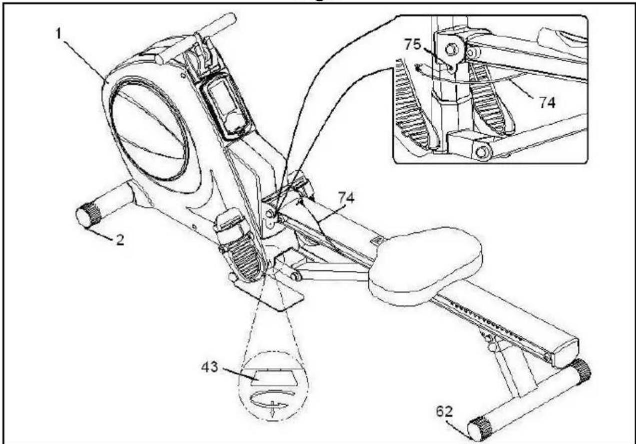
If you do not hear it click into place then pull the adjuster (43), located at the bottom of the main body (1), down toward the floor so that the knob (59) locks into position, as shown in Fig.8.
If you hear it click into position before the rear support (62) is resting on the floor, Fig.8, push the adjuster (43) in so that the three points are all level on the floor, Fig.8.
Plug the jack for the stroke counter (74) into the socket (75) located on the aluminium rail support, as shown in Fig.8.
10 FOLDING YOUR UNIT.-
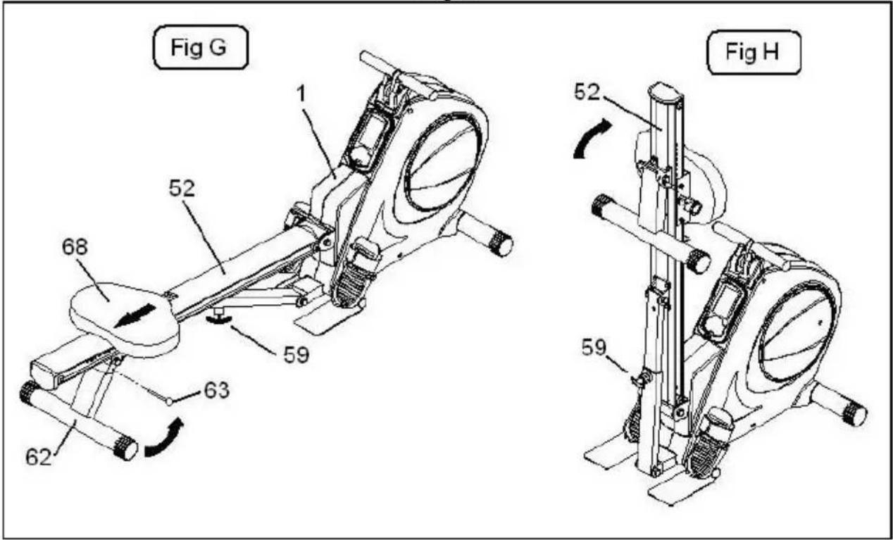
To fold your unit, Fig.9, do the following:
1.- First lock the seat (68) onto the rack on the aluminium rail (52), Fig.G. Pull out the locking pin (63) and swing the rear support (62) forward and reinsert the locking pin (63).
2.- Use one hand to pull the knob (59) back, Fig.G, and use the other hand to lift the sliding seat rail until you hear the knob (59) click into position, Fig.H.
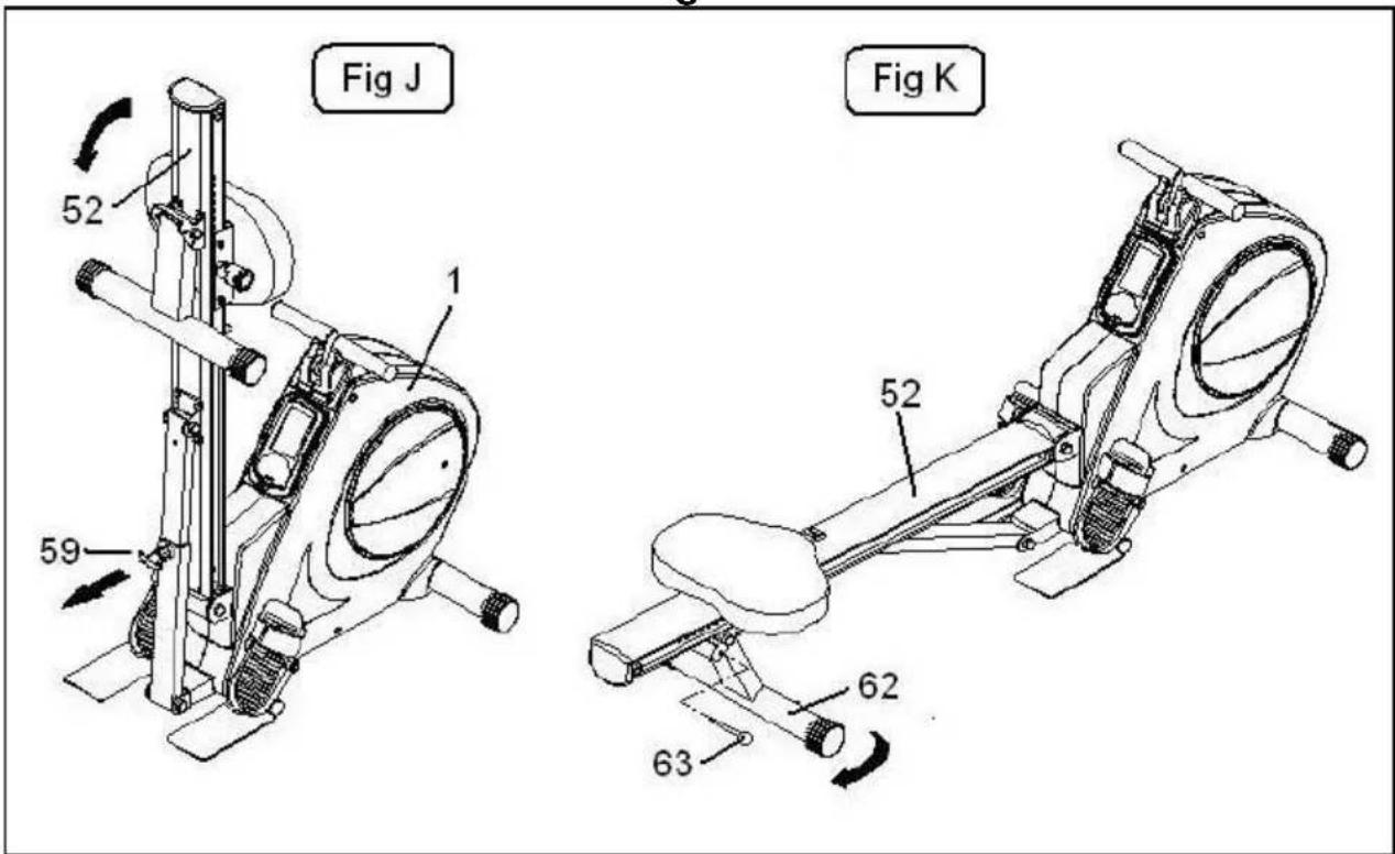
To fold your unit, Fig.10, do the following:
1.- Use one hand to pull the knob (59) back, Fig.J, and use the other hand to lower the sliding seat rail until you hear the knob (59) click into position, Fig.H.
2.- Pull out the locking pin (63) and swing the rear support (62) backward and reinsert the locking pin (63).
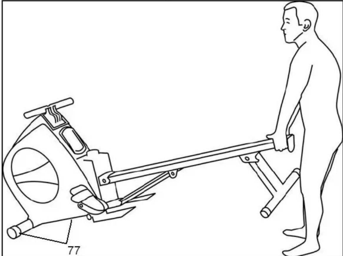
12 MOVEMENT & STORAGE.-
The unit is equipped with wheels (77) to make it easier to move. The wheels located at the front of your unit make it easier to move it into a chosen position, by lifting the rear of the unit up slightly and pushing it, as shown in Fig.11. Store your unit in a dry place, preferably not subject to changes in temperature.
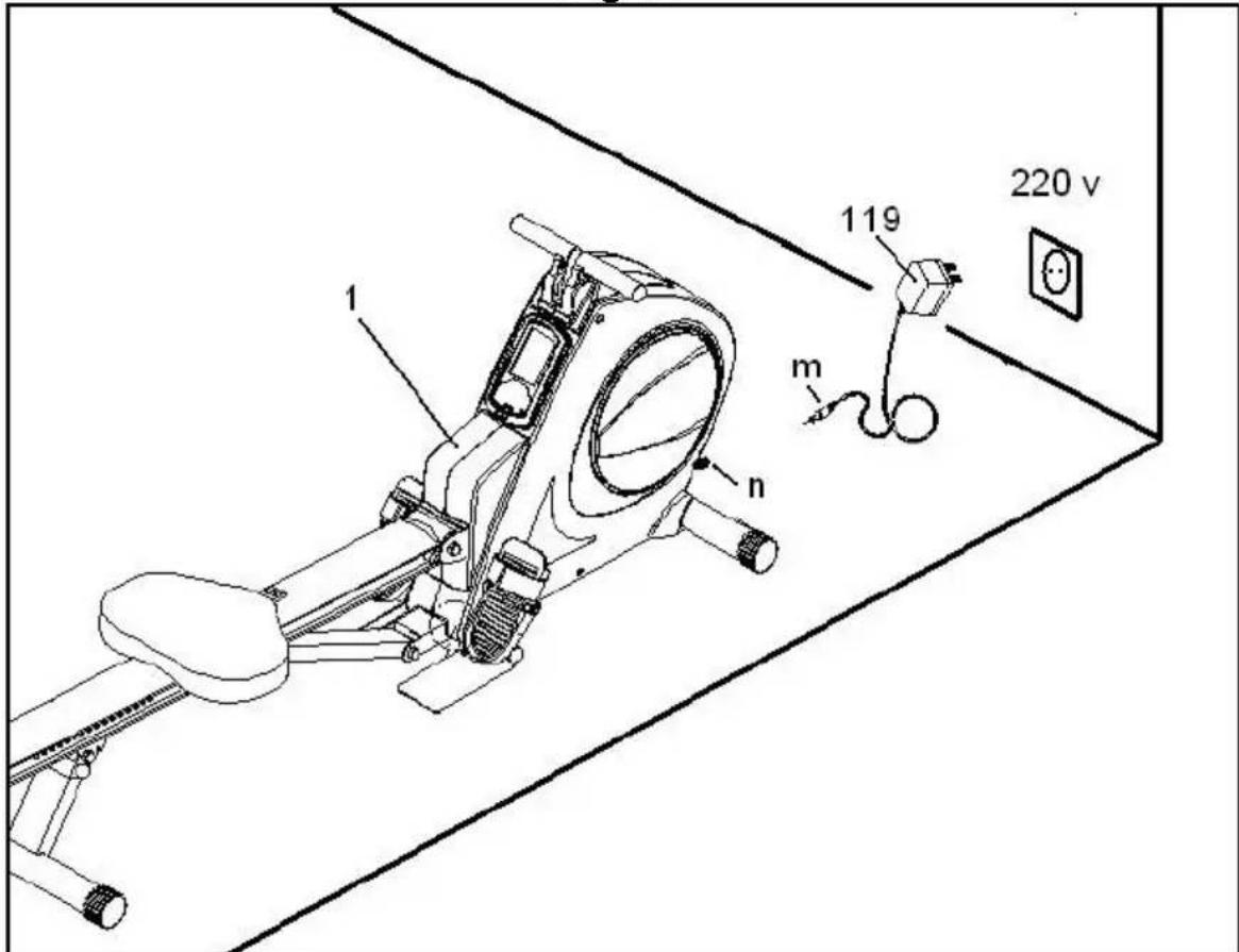
MAINS CONNECTION.-
Transformer 6 V-1Amp. Insert the jack (m) on the transformer (119) into the connection hole (n) on the main body (1) (bottom, rear of the machine) and then plug the transformer into a 220 V mains supply, Fig.12.
BH RESERVES THE RIGHT TO MODIFY THE SPECIFICATIONS OF ITS PRODUCTS WITHOUT PRIOR NOTICE
Français
Inbusschlüssel 6 mm.
natural_image
Line drawing of a person using a resistance band machine (no text or symbols)flowchart
graph TD
    A["Step 1: Left arm, Linear motion"] --> B["Step 2: Right arm, Linear motion"]
    B --> C["Step 3: Right arm, Linear motion"]
    C --> D["Step 4: Right arm, Linear motion"]
    D --> E["Step 5: Right arm, Linear motion"]
    E --> F["Step 6: Right arm, Linear motion"]
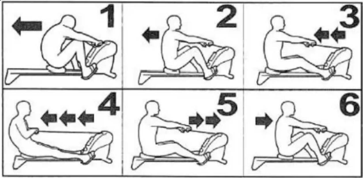
1.- ATTACK
- Arms partially stretched
- Legs brought up against the body
- Body leaning slightly forward
- Arms stretched fully out
- Begin the leg movement
- Oar above knee level
- Body moves into the upright position
3.- ACTION
- Legs pushing back
- Arms beginning to bend once they have passed the knees.
4.- END
- The rowing bar is brought to chest level
- Legs partially straightened out
- Body leaning slightly backward
5.- RECOVERY
- Arms stretched out in front
- Legs bent
6.- PREPARATION
- Return to the attack position
- Do not let go of the rowing bar
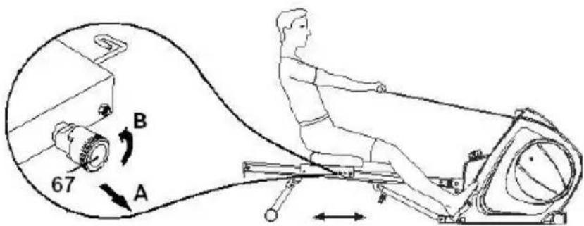
FREE MOVING SEAT:
1.- There is a locking knob (67) on the bottom right of the seat slide, to unlock it pull it outward in the direction of arrow (A) and turn it anticlockwise, arrow (B). This will free the seat from the positioner rack.
text_image
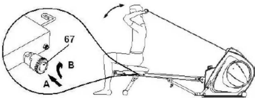
67 A BLOCKED SEAT:
1.- There is a locking knob (67) on the bottom right of the seat slide.
Position the seat on the rack, turn the knob (67) clockwise, arrow (B) then release the knob (67) as shown by arrow (A) and if you move the seat a few millimetres it will lock into position.
text_image
67 A BVARIOUS EXERCISES.
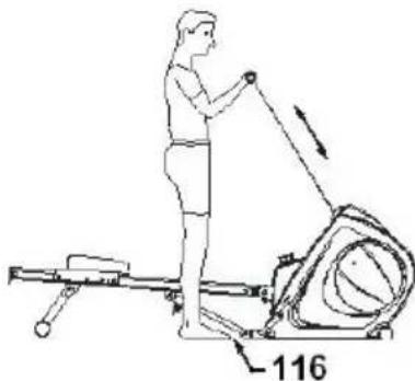
To do this exercise you have to have your feet in the pull-up foot supports (116), as shown in the diagram.
natural_image
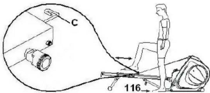
Line drawing of a person using a leg exercise machine with a weight labeled 116 (no text or symbols on the diagram itself)To do this exercise you have to attach the handgrip to the buckle (C) located at the front of the seat, with your feet in the pull-up foot supports (116), as shown in the diagram.
text_image
C 116FRANÇAIS
TECHNIQUE DU RAMEUR
flowchart
graph TD
    A["Step 1: Left arm, Linear motion"] --> B["Step 2: Right arm, Linear motion"]
    B --> C["Step 3: Right arm, Linear motion"]
    C --> D["Step 4: Right arm, Linear motion"]
    D --> E["Step 5: Right arm, Linear motion"]
    E --> F["Step 6: Right arm, Linear motion"]
1. ATTAQUE
natural_image
Line drawing of a person using a treadmill with a resistance band and numbered component (no text or symbols)natural_image
Line drawing of a person using a leg exercise machine with a weight labeled 116 (no text or symbols on the diagram itself)natural_image
Line drawing of a person using a leg presser machine with a weight labeled 116 (no text or symbols on the diagram itself)natural_image
Line drawing of a person using a stationary exercise machine with a weight labeled 116 (no text or symbols on the diagram itself)flowchart
graph TD
    A["Step 1: Sitting posture"] --> B["Step 2: Slightly elevated leg"]
    B --> C["Step 3: Slightly elevated leg"]
    C --> D["Step 4: Slightly elevated leg"]
    D --> E["Step 5: Slightly elevated leg"]
    E --> F["Step 6: Slightly elevated leg"]
1.- AANZET
natural_image
Line drawing of a person using a stationary exercise machine with a weight, showing motion direction (no text or symbols)text_image
Technical schematic diagram of a mechanical assembly with numbered components and exploded viewsTo order replacement parts:
State the machine model
Corresponding parts
n° Quantity
____
e-mail: info@bhfitness.pt
BH SERVICE PORTUGAL
Tel.: +351 234 729 510
Fax: +351 234 729 519
e-mail: info@bhfitness.pt
BH GERMANY GmbH
Altendorfer Str. 526
45355 Essen
Tel: +49 201 450910-0
e-mail:
info@bhgermany.com
Toll free: +1 866 325 2339
No.80, Jhongshan Rd.,
Daya Dist.,
Taichung City 42841,
Taiwan. R.O.C.
Tel.: +886 4 25609200
Fax: +886 4 25609280
Block A, NO.68, Branch Lane
455, Lane 822,
Zhen Nan RD., Li Zi Yuan,
Putuo, Shanghai 200331, P.R.C.
Tel: +86-021-5284 6694
Fax:+86-021-5284 6814
e-mail: info@i-bh.cn
BH FITNESS UK
Tel: 02037347554
e-mail:
sales.uk@bhfitness.com
AFTER SALES – UK
Tel.: 02074425525
e-mail:
service.uk@bhfitness.com
BH FITNESS FRANCE
SAV FRANCE
Tel : +33 0810 000 301
Fax : +33 0810 000 290
savfrance@bhfitness.com
BH SE RESERVA EL DERECHO A MODIFICAR LAS ESPECIFICACIONES DE SUS PRODUCTOS SIN PREVIO AVISO.
SPECIFICATIONS MAY BE CHANGED WITHOUT PRIOR NOTICE DUE TO OUR PROGRAMME OF CONTINUOUS PRODUCT DEVELOPMENT.
BH SE RÉSERVE LE DROIT DE MODIFIER LES SPECIFICATIONS DE SES PRODUITS SANS PRÉAVIS.