
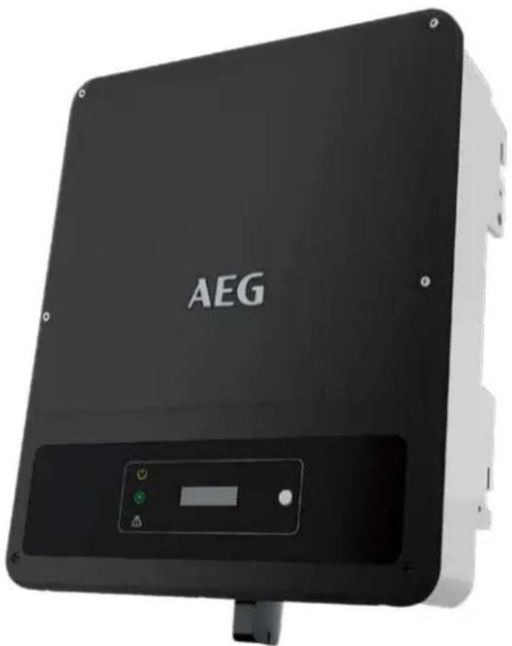
AS-IR02-5000-2 - Solar inverter AEG - Free user manual and instructions
Find the device manual for free AS-IR02-5000-2 AEG in PDF.

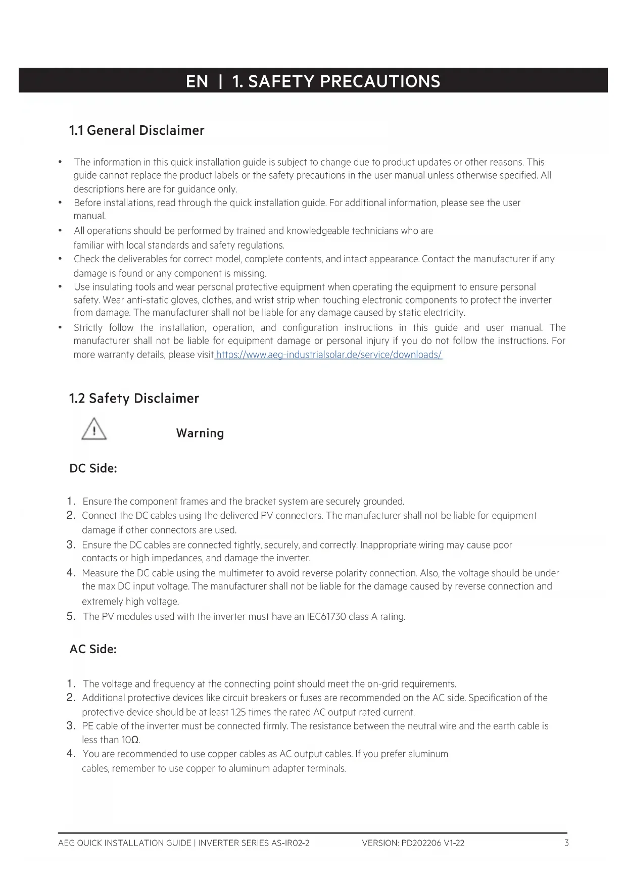


| Brand | AEG |
| Model | AS-IR02-5000-2 |
| Product type | String solar inverter |
| Rated AC power | 5000 W |
| Recommended max PV power | About 6500 Wp |
| Max DC input voltage | 1000 V |
| MPPT voltage range | 200 V – 850 V |
| Number of MPPT trackers | 2 |
| AC output voltage | 230 V single-phase |
| Output frequency | 50/60 Hz |
| Maximum efficiency | Up to 97 % |
| European efficiency | 96.5 % |
| Protection rating | IP65 |
| Dimensions (W × H × D) | About 580 × 430 × 200 mm |
| Weight | About 28 kg |
| Operating temperature range | -25 °C to +60 °C |
| Cooling | Natural convection (fanless) |
| Display and communication | LED indicators (Power, Operation, Fault) / Built-in Wi-Fi |
| Warranty | 5 years (extendable) |
| Compliance | CE, VDE-AR-N 4105, EN 50549 |
| Protection functions | Anti-islanding protection, reverse polarity protection, AC/DC overvoltage protection, temperature protection |
| Maintenance | Periodically check connections and cable condition. Clean heat sinks with a dry cloth. |
| Installation | For qualified technician only. Follow safety distances and manual instructions. |
Frequently Asked Questions - AS-IR02-5000-2 AEG
User questions about AS-IR02-5000-2 AEG
0 question about this device. Answer the ones you know or ask your own.
Ask a new question about this device
Download the instructions for your Solar inverter in PDF format for free! Find your manual AS-IR02-5000-2 - AEG and take your electronic device back in hand. On this page are published all the documents necessary for the use of your device. AS-IR02-5000-2 by AEG.
USER MANUAL AS-IR02-5000-2 AEG
VERSION: PD202206 V1-22
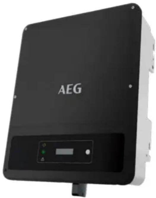
INVERTER SERIES:
AS-IR02-2
Thank you for choosing the reliability of AEG grid-tied solar inverters. This guide is intended for distributors and installers involved in the planning, installation and commissioning of photovoltaic systems. AEG grid-tied solar inverters are tested and approved by acknowledged independent certification authorities and can only be installed by qualified professional companies. Please observe the standards and regulations applying to photovoltaic systems in the relevant countries, as well as the rules of the employers' liability insurance associations for accident protection. Failure to comply with these can result in major injuries and damage. Keep this guide in a safe place for further reference as it contains important information for product care, maintenance and disposal.
Table of contents | Съдържание | | Obsah | Indholdsfortegnelse | Inhaltsverzeichnis | Πίνακας περιεχομένων | Tabla de contenidos | Sisukord | Sisällysluettelo | Table des matières | Sadržaj | Tartalomjegyzék | Indice dei contenuti | Satura rādītājs | Turinys | Inhoudsopgave | Spis treści | Índice | Cuprins | Obsah | Kazalo | Innehållsförteckning |
- Safety precautions ...2 FR ...30 SK ...60
EN ...3 HR ...33 SL ...63
BG ...6 HU ...37 SV ...66
CZ ...9 IT ...39 2. Product introduction ...69
DA ...12 LT ...42 3. Inverter installation ...70
DE ...15 LV ...45 4. Electrical connection ...73
EL ...18 NL ...48 5. Power on / off ...80
ES ...21 PL ...51 6. Commissioning ...81
ET ...24 PT ...54 7. Further information ...82
FI ...27 RO ...57
- Safety precautions
1.1 General Disclaimer
- The information in this quick installation guide is subject to change due to product updates or other reasons. This guide cannot replace the product labels or the safety precautions in the user manual unless otherwise specified. All descriptions here are for guidance only.
- Before installation, read through the quick installation guide. For additional information, please see the user manual.
- All operations should be performed by trained and knowledgeable technicians who are familiar with local standards and safety regulations.
- Check the deliverables for correct model, complete contents, and intact appearance. Contact the manufacturer if any damage is found or any component is missing.
- Use insulating tools and wear personal protective equipment when operating the equipment to ensure personal safety. Wear anti-static gloves, clothes, and wrist strap when touching electronic components to protect the inverter from damage. The manufacturer shall not be liable for any damage caused by static electricity.
- Strictly follow the installation, operation, and configuration instructions in this guide and user manual. The manufacturer shall not be liable for equipment damage or personal injury if you do not follow the instructions. For more warranty details, please visit https://www.aeg-industrialsolar.de/service/downloads/
1.2 Safety Disclaimer

Warning
DC Side:
- Ensure the component frames and the bracket system are securely grounded.
- Connect the DC cables using the delivered PV connectors. The manufacturer shall not be liable for equipment damage if other connectors are used.
- Ensure the DC cables are connected tightly, securely, and correctly. Inappropriate wiring may cause poor contacts or high impedances, and damage the inverter.
- Measure the DC cable using the multimeter to avoid reverse polarity connection. Also, the voltage should be under the max DC input voltage. The manufacturer shall not be liable for the damage caused by reverse connection and extremely high voltage.
- The PV modules used with the inverter must have an IEC61730 class A rating.
AC Side:
- The voltage and frequency at the connecting point should meet the on-grid requirements.
- Additional protective devices like circuit breakers or fuses are recommended on the AC side. Specification of the protective device should be at least 1.25 times the rated AC output rated current.
- PE cable of the inverter must be connected firmly. The resistance between the neutral wire and the earth cable is less than 10Ω .
- You are recommended to use copper cables as AC output cables. If you prefer aluminum cables, remember to use copper to aluminum adapter terminals.
Product :
- Do not apply mechanical load to the terminals, otherwise the terminals can be damaged.
- All labels and warning marks should be visible after the installation. Do not scrawl, damage, or cover any label on the device.
- Unauthorized dismantling or modification may damage the equipment, the damage is not covered under the warranty.
- Install the inverter away from high magnetic field to avoid electromagnetic interference. If there is any radio or wireless communication equipment below 30MHz near the inverter, you have to:
• Install the inverter at least 30m far away from the wireless equipment.
- Add a low pass EMI filter or a multi winding ferrite core to the DC input cable or AC output cable of the inverter.
- Warning labels on the inverter are as follows.
 | HIGH VOLTAGE HAZARD.Disconnect all incoming power and turn off the product before working on it. | 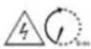 | Delayed discharge. Wait 5 minutes after power off until the components are completely discharged. |
 | Read through the guide before working on this device. |  | Potential risks exist. Wear proper PPE before any operations. |
 | High-temperature hazard. Do not touch the product under operation to avoid being burnt. |  | Grounding point. Indicates the position for connecting the PE cable. |
 | CE marking |  | Do not dispose of the inverter as household waste.Discard the product in compliance with local laws and regulations, or send it back to the manufacturer. |
1.3 Check before power-on
| No | Check item | |
| 1 | ☐ | The product is firmly installed at a clean place that is well-ventilated and easy-to-operate. |
| 2 | ☐ | The PE, DC input, AC output, and communication cables are connected correctly and securely. |
| 3 | ☐ | Cable ties are intact, routed properly and evenly. |
| 4 | ☐ | Unused ports and terminals are sealed. |
| 5 | ☐ | The voltage and frequency at the connection point meet the inverter grid connection requirements. |
1.4 EU Declaration of Conformity
Solar Solutions hereby declares that the inverter with wireless communication modules sold in the European market meets the requirements of the following directives:
• Radio Equipment Directive 2014/53/EU (RED) • Restrictions of Hazardous Substances Directive 2011/65/EU and (EU) 2015/863 (RoHS) • Waste Electrical and Electronic Equipment 2012/19/EU • Registration, Evaluation, Authorisation and Restriction of Chemicals (EC) No 1907/2006 (REACH)
Solar Solutions hereby declares that the inverter without wireless communication modules sold in the European market meets the requirements of the following directives:
• Electromagnetic compatibility Directive 2014/30/EU (EMC) • Electrical Apparatus Low Voltage Directive 2014/35/EU (LVD) • Restrictions of Hazardous Substances Directive 2011/65/EU and (EU) 2015/863 (RoHS) • Waste Electrical and Electronic Equipment 2012/19/EU • Registration, Evaluation, Authorisation and Restriction of Chemicals (EC) No 1907/2006 (REACH)
You can download the EU Declaration of Conformity on https://www.aeg-industrialsolar.de/service/downloads/.
1.5. LED Indicators
| Indicator | Status | Description |
 Power Power | ON = WiFi is connected/active. | |
| BLINK 1 = WiFi system is resetting. | ||
| BLINK 2 = WiFi not connect to the router. | ||
| BLINK 4 = WiFi server problem. | ||
| BLINK = RS485 is connected. | ||
| OFF = WiFi is not active. | ||
 Operating Operating | ON = The inverter is feeding power. | |
| OFF = The inverter is not feeding power at the moment. | ||
 Faulty Faulty | ON = A fault has occurred. | |
| OFF = No fault. |
1.2 Safety Declaration

Warning
WiFi/LAN/4G Communication
Module Port or RS485
Communication Cable Port
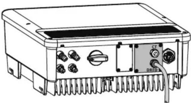
DRED/CT/Remote
- Shutdown Communication Cable Port
- AC Output Terminal 6. Indicator
- LCD
8.
Button
9.
PE Terminal
- Mounting Plate 11. Heat Sink
Dimensions
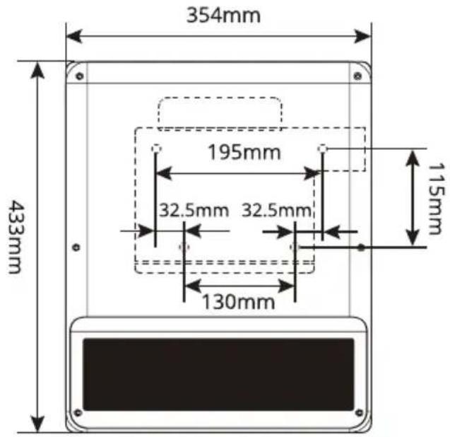
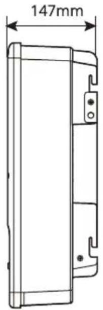
- Inverter Installation
PACKING LIST × 1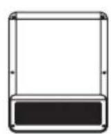
× 1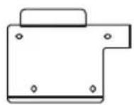
x N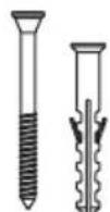
x 2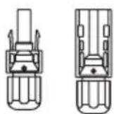
x 1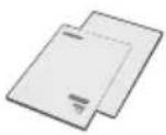
x 1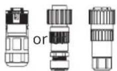
× N × N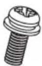

× N × 1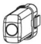
N = Quantity depends on the inverter model
Space Requirements
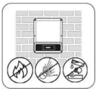
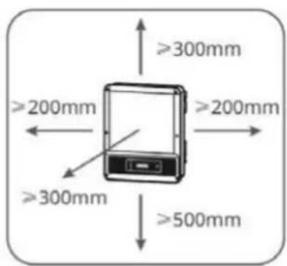
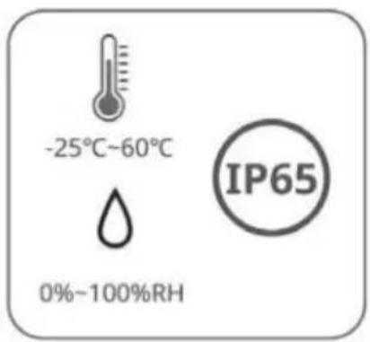
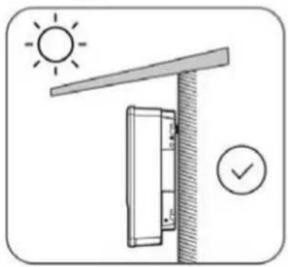
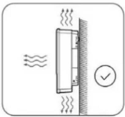
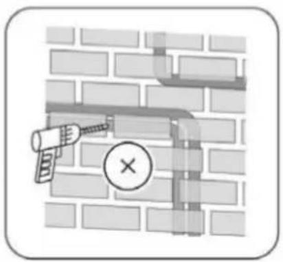
Angle Requirements
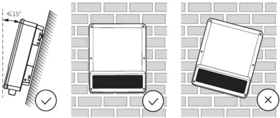
Installing the Inverter
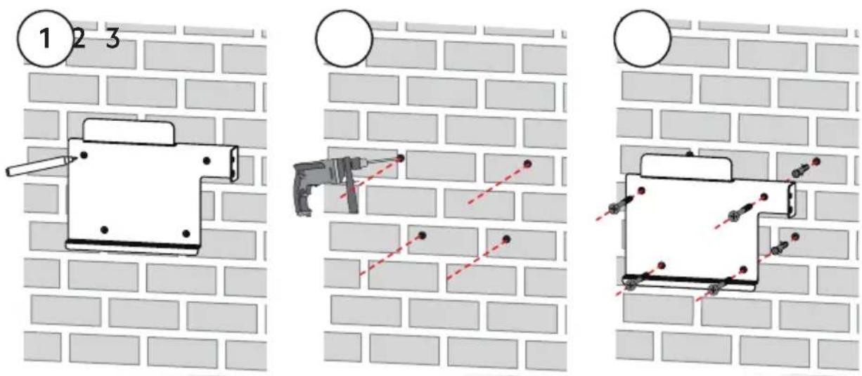
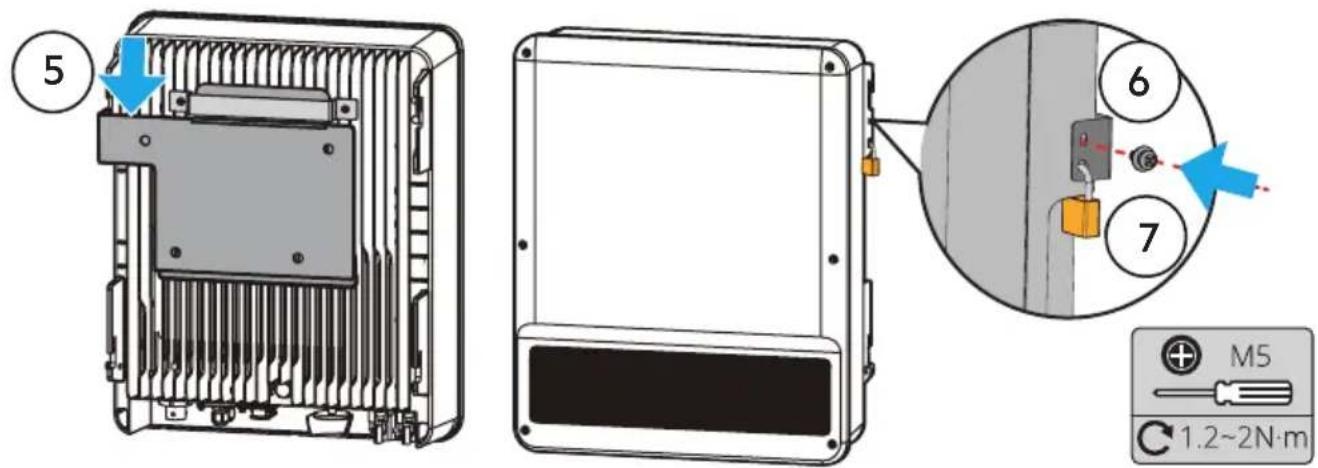
- Electrical Connection
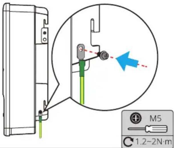
PE Cable
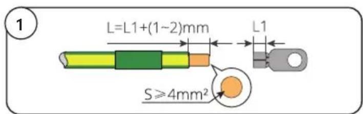
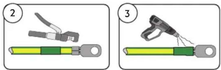
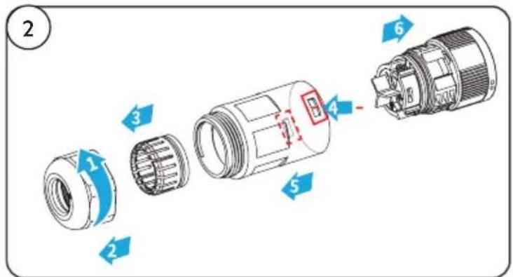
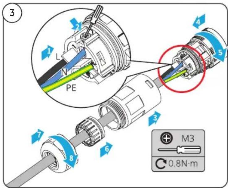
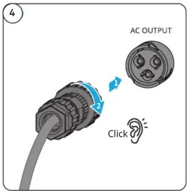
AC Cable
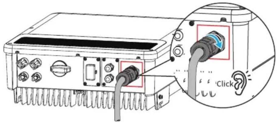
AC-1
or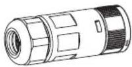
AC-2 AC-3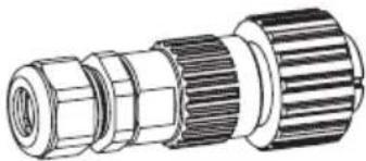
or
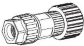
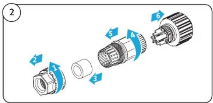
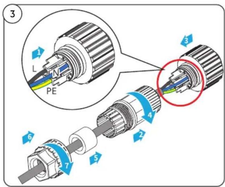
AC-1 Connector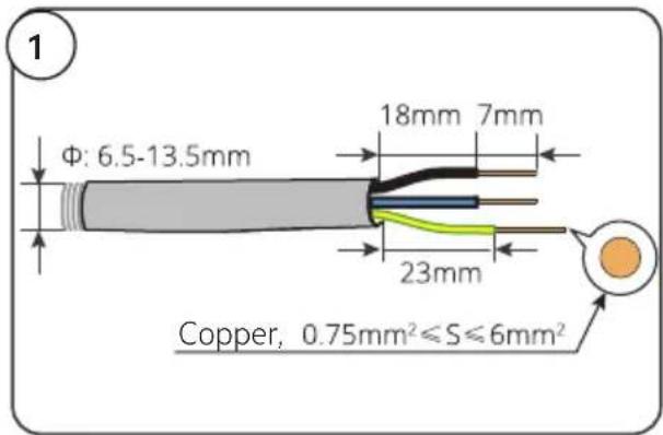
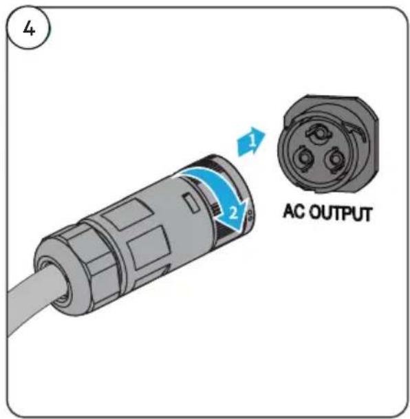
AC-2 Connector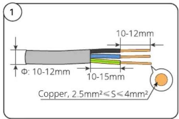
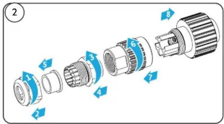
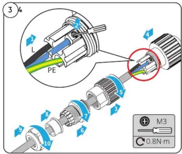
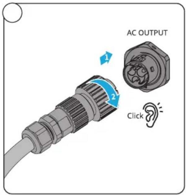
AC-3 Connector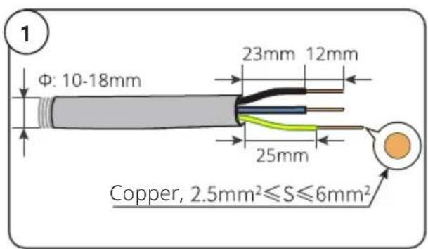
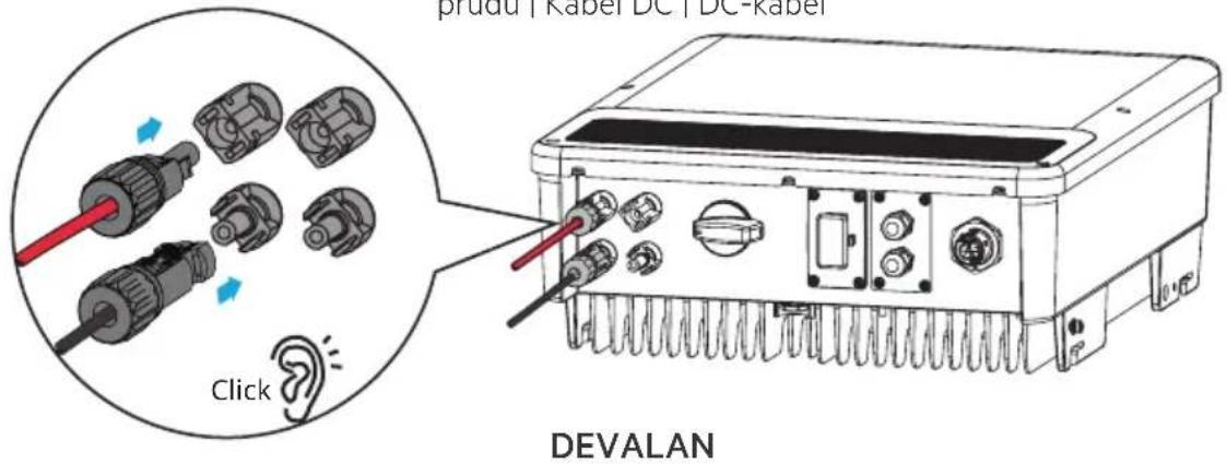
DC Cable
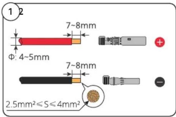
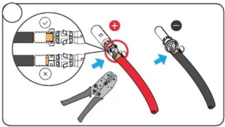
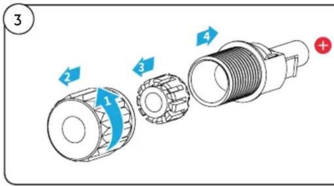
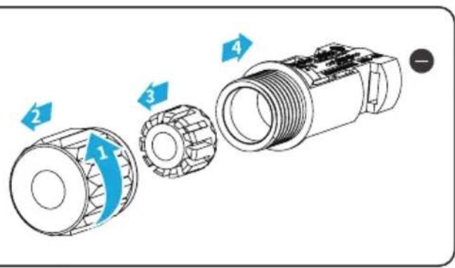
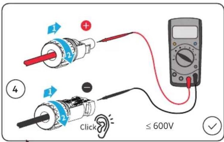
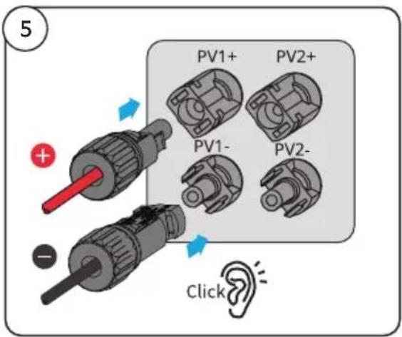
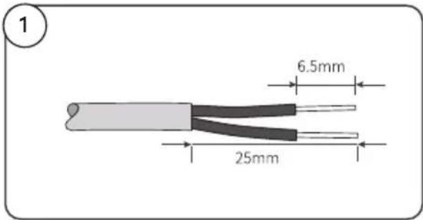
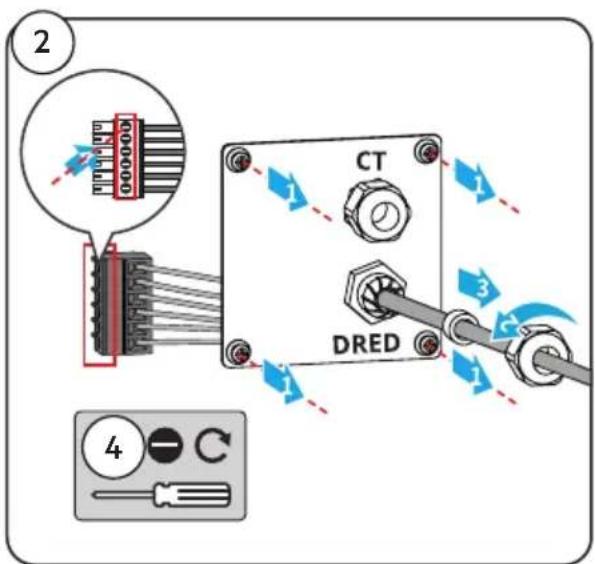
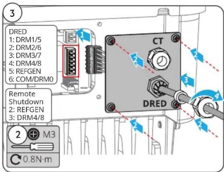
DRED/Remote Shutdown Communication Cable
• DRED: Australia • Remote Shutdown: Europe
CT Communication Cable
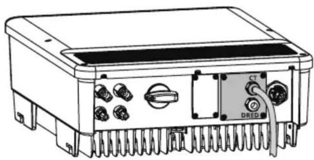
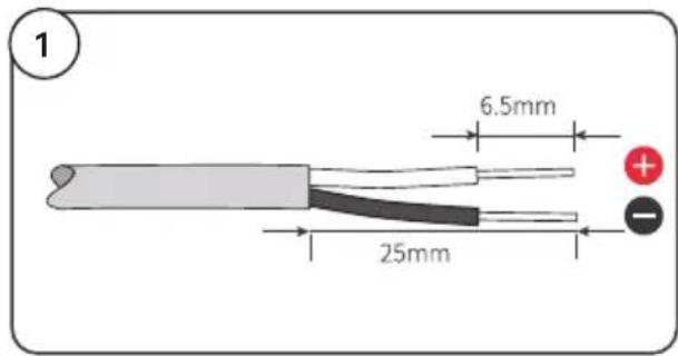
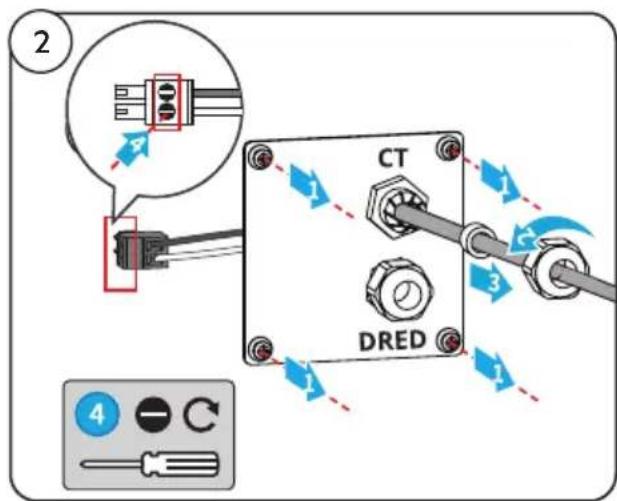
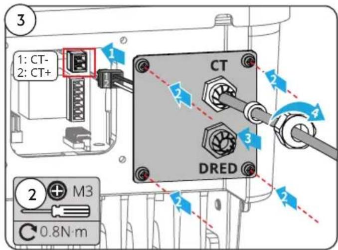
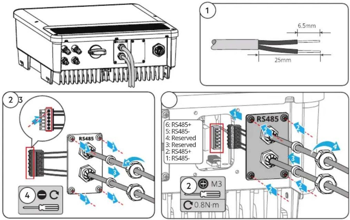
RS485 Communication Cable
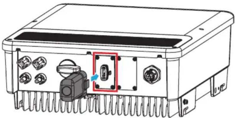
Communication Module
WiFi kit, 4G kit, LAN kit, GPRS, Wi-Fi/LAN Kit module: optional.
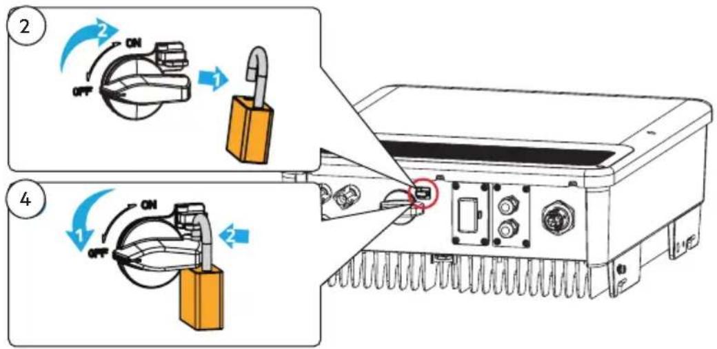
- Power On and Off
![graph LR A["PV"] --> B["DC Isolator (Optional)"] C["3"] --> D["Inverter"] E["1"] --> F["AC Breaker"] F --> G["Grid"] H["ON OFF"] --> I["LED System"]](/content/2026/04/646313/images/3b3e38c9e6586c780b1e4c4a85796712b36d89f704ab1486ee0a804c47467f58.jpg)
Check the LED indicators
![graph LR A["Turn on"] --> B["31"] B --> C["2"] D["Turn off"] --> E["31"] E --> F["4"]](/content/2026/04/646313/images/1f5db3ade5a0ed983506f053dfbe23f2f6c383a41363cb5b819c918148c04fc2.jpg)
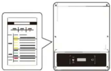
- Commissioning
Commissioning via LCD
![graph TD A["Select Country/Region"] -->|2s long press| B["Country code 1"] B --> C["Country code 2"] D["Normal Pac=2595.5W"] -->|20s wait| C](/content/2026/04/646313/images/5a245c8e3bfdbc8782b6e818bcc0f16cf53943d83920406789f80591fa84c653.jpg)
For WI-FI Configuration refer to:
WiFi Configuration Guide
Monitoring via Portal
https://www.pvsolarportal.com/home/login
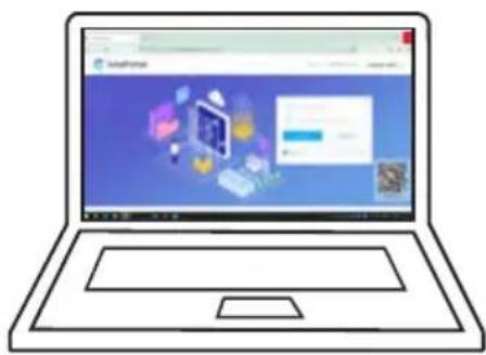
SolarPortal


- Further information
For more detailed instructions see:
www.aeg-industrialsolar.de/solar-inverters/ www.aeg-industrialsolar.de/service/downloads/
(Choose the appropriate model)
NOTES
Solar Solutions Products BV
Finlandlaan 1 2391PV Hazerswoude-Dorp The Netherlands
service@aeg-industrialsolar.de | www.aeg-industrialsolar.de
AEG is a registered trademark used under license from AB Electrolux (publ).
- TABLE OF CONTENTS | СЪДЪРЖАНИЕ | | OBSAH | INDHOLDSFORTEGNELSE | INHALTSVERZEICHNIS | ΠΊΝΑΚΑΣ ΠΕΡΙΕΧΟΜΈΝΩΝ | TABLA DE CONTENIDOS | SISUKORD | SISÄLLYSLUETTELO | TABLE DES MATIÈRES | SADRŽAJ | TARTALOMJEGYZÉK | INDICE DEI CONTENUTI | SATURA RĀDĪTĀJS | TURINYS | INHOUDSOPGAVE | SPIS TREŚCI | ÍNDICE | CUPRINS | OBSAH | KAZALO | INNEHÅLLSFÖRTECKNING
- GENERAL DISCLAIMER
- SAFETY DISCLAIMER
- WARNING
- DC SIDE
- AC SIDE
- PRODUCT
- CHECK BEFORE POWER-ON
- EU DECLARATION OF CONFORMITY
- LED INDICATORS
- SAFETY DECLARATION
- NOTES
Brand : AEG
Model : AS-IR02-5000-2
Category : Solar inverter