
CD3605DA - Saw HiKOKI - Free user manual and instructions
Find the device manual for free CD3605DA HiKOKI in PDF.

| Product Type | Cordless Metal Saw |
| Brand | HiKOKI |
| Model | CD3605DA |
| Rated Voltage | 36 V |
| No-Load Speed | 3600 min⁻¹ (Power mode) / 2400 min⁻¹ (Silent mode) |
| Cutting Depth at 90° | 46 mm |
| Blade Diameter | 125 mm |
| Weight | 2.8 kg (with BSL36A18X) – 3.1 kg (with BSL36B18X) |
| Compatible Battery | Multi-volt (BSL36A18X, BSL36B18X) |
| Compatible Charger | UC18YSL3 |
| Main Features | Soft start, overload and overheat protection, silent mode, LED lighting, electric brake, battery indicator |
| Noise Level | Sound pressure: 106 dB(A) / Sound power: 114 dB(A) |
| Vibration Level | 2.1 m/s² (metal cutting) |
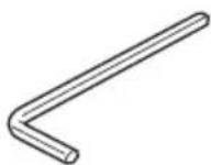
| Included Accessories | Carbide-tipped saw blade (28 teeth), hex key, guide |
| Maintenance and Cleaning | Regular cleaning of the saw cover, check screws, sharpen or replace blade |
| Safety | Lower guard, switch lock, battery protection (overheat, overload), auto-stop |
| Spare Parts and Repairability | Replacement parts available through HiKOKI authorized service |
| General Information | Warranty in accordance with national regulations, covers manufacturing defects |
Frequently Asked Questions - CD3605DA HiKOKI
User questions about CD3605DA HiKOKI
0 question about this device. Answer the ones you know or ask your own.
Ask a new question about this device
Download the instructions for your Saw in PDF format for free! Find your manual CD3605DA - HiKOKI and take your electronic device back in hand. On this page are published all the documents necessary for the use of your device. CD3605DA by HiKOKI.
USER MANUAL CD3605DA HiKOKI
natural_image
Technical line drawing of a mechanical cutting tool with a flat blade and mounting base (no text or symbols)
en Handling instructions
de Bedienungsanleitung
fr Mode d'emploi
it Istruzioni per l'uso
nl Gebruiksaanwijzing
es Instrucciones de manejo
pt Instruções de uso
sv Bruksanvisning
da Brugsanvisning
no Bruksanvisning
fi Käyttöohjeet
el Οδηγίες χειρισμού
pl Instrukcja obsługi
hu Kezelési utasítás
cs Návod k obsluze
tr Kullanım talimatları
ro Instructiuni de utilizare
sl Navodila za rokovanje
sk Pokyny na manipuláciu
bg Инструкция за експлоатация
sr Uputstvo za rukovanje
hr Upute za rukovanje
1
2
natural_image
Technical line drawing of a mechanical device on a flat surface with supports (no text or symbols)3
4
natural_image
Technical line drawing of a mechanical device with hands operating it (no text or symbols visible)5
natural_image
Illustration of a hand using a tool to lift a rabbit on a metal frame (no text or symbols)6
natural_image
Illustration of a hand using a tool to cut a piece of meat on a flat surface, with an arrow indicating motion (no text or symbols present)7
natural_image
Technical line drawing of a hand using a tool to adjust or install a mechanical component (no text or symbols visible)8
natural_image
Illustration of a mechanical device with motion arrows indicating movement (no text or symbols)9
10
natural_image
Technical line drawing of a mechanical component with no visible text or symbols11 12
13 14
flowchart
graph TD
    A["ON OFF"] --> B["ON OFF"]
    B --> C["ON OFF"]
    C --> D["ON OFF"]
    D --> E["ON OFF"]
    E --> F["ON OFF"]
    F --> G["ON OFF"]
    G --> H["ON OFF"]
    H --> I["ON OFF"]
    I --> J["ON OFF"]
    J --> K["ON OFF"]
    K --> L["ON OFF"]
    L --> M["ON OFF"]
    M --> N["ON OFF"]
    N --> O["ON OFF"]
    O --> P["ON OFF"]
    P --> Q["ON OFF"]
    Q --> R["ON OFF"]
    R --> S["ON OFF"]
    S --> T["ON OFF"]
    T --> U["ON OFF"]
    U --> V["ON OFF"]
    V --> W["ON OFF"]
    W --> X["ON OFF"]
    X --> Y["ON OFF"]
    Y --> Z["ON OFF"]
    Z --> AA["ON OFF"]
    AA --> AB["ON OFF"]
    AB --> AC["ON OFF"]
    AC --> AD["ON OFF"]
    AD --> AE["ON OFF"]
    AE --> AF["ON OFF"]
    AF --> AG["ON OFF"]
    AG --> AH["ON OFF"]
    AH --> AI["ON OFF"]
    AI --> AJ["ON OFF"]
    AJ --> AK["ON OFF"]
    AK --> AL["ON OFF"]
    AL --> AM["ON OFF"]
    AM --> AN["ON OFF"]
    AN --> AO["ON OFF"]
    AO --> AP["ON OFF"]
    AP --> AQ["ON OFF"]
    AQ --> AR["ON OFF"]
    AR --> AS["ON OFF"]
    AS --> AT["ON OFF"]
    AT --> AU["ON OFF"]
    AU --> AV["ON OFF"]
    AV --> AW["ON OFF"]
    AW --> AX["ON OFF"]
    AX --> AY["ON OFF"]
15
16
17 18
19
natural_image
Line drawing of a hand using a tool to adjust or install a mechanical component (no text or symbols present)20
21
flowchart
graph TD
    A["Step 1: Cutting"] --> B["Step 2: Assembly"]
    B --> C["Step 3: Rotation"]
    C --> D["Step 4: Cut"]
    D --> E["Step 5: Rotation"]
    E --> F["Step 6: Cut"]
    F --> G["Step 7: Assembly"]
    G --> H["Step 8: Rotation"]
    H --> I["Step 9: Cut"]
    I --> J["Step 10: Final Assembly"]
    style A fill:#f9f,stroke:#333
    style B fill:#f9f,stroke:#333
    style C fill:#f9f,stroke:#333
    style D fill:#f9f,stroke:#333
    style E fill:#f9f,stroke:#333
    style F fill:#f9f,stroke:#333
    style G fill:#f9f,stroke:#333
    style H fill:#f9f,stroke:#333
    style I fill:#f9f,stroke:#333
    style J fill:#f9f,stroke:#333
22
23
24 25
26 27
28 29
30
GENERAL POWER TOOL SAFETY WARNINGS

WARNING
Read all safety warnings, instructions, illustrations and specifications provided with this power tool.
Failure to follow all instructions listed below may result in electric shock, fi re and/or serious injury.
Save all warnings and instructions for future reference.
The term “power tool” in the warnings refers to your mains-operated (corded) power tool or battery-operated (cordless) power tool.
1) Work area safety
a) Keep work area clean and well lit.
Cluttered or dark areas invite accidents.
b) Do not operate power tools in explosive atmospheres, such as in the presence of fl ammable liquids, gases or dust.
Power tools create sparks which may ignite the dust or fumes.
c) Keep children and bystanders away while operating a power tool.
Distractions can cause you to lose control.
2) Electrical safety
a) Power tool plugs must match the outlet. Never modify the plug in any way. Do not use any adapter plugs with earthed (grounded) power tools.
Unmodified plugs and matching outlets will reduce risk of electric shock.
b) Avoid body contact with earthed or grounded surfaces, such as pipes, radiators, ranges and refrigerators.
There is an increased risk of electric shock if your body is earthed or grounded.
c) Do not expose power tools to rain or wet conditions.
Water entering a power tool will increase the risk of electric shock.
d) Do not abuse the cord. Never use the cord for carrying, pulling or unplugging the power tool.
Keep cord away from heat, oil, sharp edges or moving parts.
Damaged or entangled cords increase the risk of electric shock.
e) When operating a power tool outdoors, use an extension cord suitable for outdoor use.
Use of a cord suitable for outdoor use reduces the risk of electric shock.
f) If operating a power tool in a damp location is unavoidable, use a residual current device (RCD) protected supply.
Use of an RCD reduces the risk of electric shock.
3) Personal safety
a) Stay alert, watch what you are doing and use common sense when operating a power tool.
Do not use a power tool while you are tired or under the influence of drugs, alcohol or medication.
A moment of inattention while operating power tools may result in serious personal injury.
b) Use personal protective equipment. Always wear eye protection.
Protective equipment such as a dust mask, non-skid safety shoes, hard hat or hearing protection used for appropriate conditions will reduce personal injuries.
c) Prevent unintentional starting. Ensure the switch is in the off -position before connecting to power source and/or battery pack, picking up or carrying the tool.
Carrying power tools with your fi nger on the switch or energising power tools that have the switch on invites accidents.
d) Remove any adjusting key or wrench before turning the power tool on.
A wrench or a key left attached to a rotating part of the power tool may result in personal injury.
e) Do not overreach. Keep proper footing and balance at all times.
This enables better control of the power tool in unexpected situations.
f) Dress properly. Do not wear loose clothing or jewellery. Keep your hair and clothing away from moving parts.
Loose clothes, jewellery or long hair can be caught in moving parts.
g) If devices are provided for the connection of dust extraction and collection facilities, ensure these are connected and properly used.
Use of dust collection can reduce dust-related hazards.
h) Do not let familiarity gained from frequent use of tools allow you to become complacent and ignore tool safety principles.
A careless action can cause severe injury within a fraction of a second.
4) Power tool use and care
a) Do not force the power tool. Use the correct power tool for your application.
The correct power tool will do the job better and safer at the rate for which it was designed.
b) Do not use the power tool if the switch does not turn it on and off.
Any power tool that cannot be controlled with the switch is dangerous and must be repaired.
c) Disconnect the plug from the power source and/or remove the battery pack, if detachable, from the power tool before making any adjustments, changing accessories, or storing power tools.
Such preventive safety measures reduce the risk of starting the power tool accidentally.
d) Store idle power tools out of the reach of children and do not allow persons unfamiliar with the power tool or these instructions to operate the power tool.
Power tools are dangerous in the hands of untrained users.
e) Maintain power tools and accessories. Check for misalignment or binding of moving parts, breakage of parts and any other condition that may affect the power tool's operation. If damaged, have the power tool repaired before use.
Many accidents are caused by poorly maintained power tools.
f) Keep cutting tools sharp and clean.
Properly maintained cutting tools with sharp cutting edges are less likely to bind and are easier to control.
g) Use the power tool, accessories and tool bits etc. in accordance with these instructions, taking into account the working conditions and the work to be performed.
Use of the power tool for operations different from those intended could result in a hazardous situation.
h) Keep handles and grasping surfaces dry, clean and free from oil and grease.
Slippery handles and grasping surfaces do not allow for safe handling and control of the tool in unexpected situations.
English
5) Battery tool use and care
a) Recharge only with the charger specified by the manufacturer.
A charger that is suitable for one type of battery pack may create a risk of fire when used with another battery pack.
b) Use power tools only with specifically designated battery packs.
Use of any other battery packs may create a risk of injury and fire.
c) When battery pack is not in use, keep it away from other metal objects, like paper clips, coins, keys, nails, screws or other small metal objects, that can make a connection from one terminal to another.
Shorting the battery terminals together may cause burns or a fire.
d) Under abusive conditions, liquid may be ejected from the battery; avoid contact. If contact accidentally occurs, fl ush with water. If liquid contacts eyes, additionally seek medical help.
Liquid ejected from the battery may cause irritation or burns.
e) Do not use a battery pack or tool that is damaged or modified.
Damaged or modified batteries may exhibit unpredictable behaviour resulting in fire, explosion or risk of injury.
f) Do not expose a battery pack or tool to fire or excessive temperature.
Exposure to fire or temperature above 130 °C cause explosion.
g) Follow all charging instructions and do not charge the battery pack or tool outside the temperature range specified in the instructions.
Charging improperly or at temperatures outside the specified range may damage the battery and increase the risk of fi re.
6) Service
a) Have your power tool serviced by a qualified repair person using only identical replacement parts.
This will ensure that the safety of the power tool is maintained.
b) Never service damaged battery packs.
Service of battery packs should only be performed by the manufacturer or authorized service providers.
PRECAUTION
Keep children and infi rm persons away.
When not in use, tools should be stored out of reach of children and infi rm persons.
CORDLESS METAL CUTTING SAW SAFETY WARNINGS
Cutting procedures
a) ⚠️DANGER: Keep hands away from cutting area and the blade.
If both hands are holding the saw, they cannot be cut by the blade.
b) Do not reach underneath the workpiece.
The guard cannot protect you from the blade below the workpiece.
c) Adjust the cutting depth to the thickness of the workpiece.
Less than a full tooth of the blade teeth should be visible below the workpiece.
d) Never hold the workpiece in your hands or across your leg while cutting. Secure the workpiece to a stable platform.
It is important to support the work properly to minimize body exposure, blade binding, or loss of control.
e) Hold the power tool by insulated gripping surfaces, when performing an operation where the cutting tool may contact hidden wiring.
Contact with a “live” wire will also make exposed metal parts of the power tool “live” and could give the operator an electric shock.
f) When ripping, always use a rip fence or straight edge guide.
This improves the accuracy of cut and reduces the chance of blade binding.
g) Always use blades with correct size and shape (diamond versus round) of arbour holes.
Blades that do not match the mounting hardware of the saw will run off -centre, causing loss of control.
h) Never use damaged or incorrect blade washers or bolt.
The blade washers and bolt were specially designed for your saw, for optimum performance and safety of operation.
Kickback causes and related warnings
- kickback is a sudden reaction to a pinched, jammed or misaligned saw blade, causing an uncontrolled saw to lift up and out of the workpiece toward the operator;
- when the blade is pinched or jammed tightly by the kerf may closing down, the blade stalls and the motor reaction drives the unit rapidly back toward the operator;
- if the blade becomes twisted or misaligned in the cut, the teeth at the back edge of the blade can dig into the top surface of the wood causing the blade to climb out of the kerf and jump back toward the operator.
Kickback is the result of saw misuse and/or incorrect operating procedures or conditions and can be avoided by taking proper precautions as given below.
a) Maintain a firm grip on the saw and position your arms to resist kickback forces. Position your body to either side of the blade, but not in line with the blade.
Kickback could cause the saw to jump backwards, but kickback forces can be controlled by the operator, if proper precautions are taken.
b) When blade is binding, or when interrupting a cut for any reason, release the trigger and hold the saw motionless in the material until the blade comes to a complete stop.
Never attempt to remove the saw from the work or pull the saw backward while the blade is in motion or kickback may occur.
Investigate and take corrective actions to eliminate the cause of blade binding.
c) When restarting a saw in the workpiece, centre the saw blade in the kerf so that the saw teeth are not engaged into the material.
If a saw blade binds, it may walk up or kickback from the workpiece as the saw is restarted.
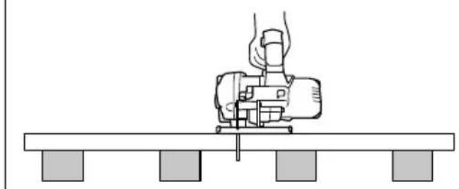
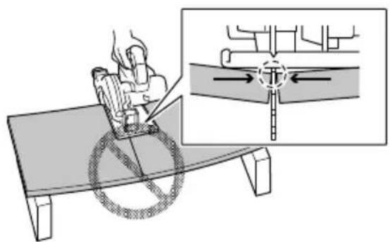
d) Support large panels to minimise the risk of blade pinching and kickback.
Large panels tend to sag under their own weight. Supports must be placed under the panel on both sides, near the line of cut and near the edge of the panel.
e) Do not use dull or damaged blades.
Unsharpened or improperly set blades produce narrow kerf causing excessive friction, blade binding and kickback.
f) Blade depth lever must be tight and secure before making the cut.
If blade adjustment shifts while cutting, it may cause binding and kickback.
g) Use extra caution when sawing into existing walls or other blind areas.
The protruding blade may cut objects that can cause kickback.
Lower guard function
a) Check the lower guard for proper closing before each use. Do not operate the saw if the lower guard does not move freely and close instantly. Never clamp or tie the lower guard into the open position.
If the saw is accidentally dropped, the lower guard may be bent.
Raise the lower guard with the retracting handle and make sure it moves freely and does not touch the blade or any other part, in all angles and depths of cut.
b) Check the operation of the lower guard spring. If the guard and the spring are not operating properly, they must be serviced before use.
Lower guard may operate sluggishly due to damaged parts, gummy deposits, or a build-up of debris.
c) Lower guard may be retracted manually only for special cuts such as "plunge cuts" and "compound cuts".
Raise the lower guard by the retracting handle and as soon as the blade enters the material, the lower guard must be released.
For all other sawing, the lower guard should operate automatically.
d) Always observe that the lower guard is covering the blade before placing the saw down on bench or floor.
An unprotected, coasting blade will cause the saw to walk backwards, cutting whatever is in its path.
Be aware of the time it takes for the blade to stop after switch is released.
ADDITIONAL SAFETY WARNINGS
- Do not allow foreign matter to enter the hole for connecting the rechargeable battery.
- Never disassemble the rechargeable battery and charger.
- Never short-circuit the rechargeable battery. Shortcircuiting the battery will cause a great electric current and overheat. It results in burn or damage to the battery.
- Do not dispose of the battery in fire. If the battery is burnt, it may explode.
- When using this unit continuously, the unit may overheat, leading to damage in the motor and switch. Please leave it without using it for approximately 15 minutes.
- Do not insert object into the air ventilation slots of the charger. Inserting metal objects or inflammables into the charger air ventilation slots will result in electrical shock hazard or damaged charger.
- Using an exhausted battery will damage the charger.
- Bring the battery to the shop from which it was purchased as soon as the post-charging battery life becomes too short for practical use. Do not dispose of the exhausted battery.
- Wear earplugs to protect your ears during operation.
- Use only blade diameter specified on the machine.
- Do not use any abrasive wheel.
- Do not use saw blades which are deformed or cracked.
- Do not use saw blades made of high speed steel.
- Do not use saw blades which do not comply with the characteristics specified in these instructions.
-
Do not stop the saw blades by lateral pressure on the disc.
-
Always keep the saw blades sharp.
- Ensure that the lower guard moves smoothly and freely.
- Never use the circular saw with its lower guard fixed in the open position.
- Ensure that the retraction mechanism of the guard system operates correctly.
- Never operate the circular saw with the saw blade turned upward or to the side.
- Ensure that the material is free of foreign matters such as nails.
- The saw blades shall be 125 mm.
- Pull out battery before carrying out any adjustment, servicing or maintenance.
- Be careful of brake kickback.
This circular saw features an electric brake that functions when the switch is released. As there is some kickback when the brake functions, be sure to hold the main body securely. - Ensure that the power source to be utilized conforms to the power requirements specified on the product nameplate.
- Ensure that the switch is in the OFF position. If the battery installed to power tool while the switch is in the ON position, the power tool will start operating immediately, which could cause a serious accident.
- Avoid cutting in the state where the base has floated up from the material.
When blade is binding, or when interrupting a cut for any reason, release the trigger and hold the saw motionless in the material until the blade comes to a complete stop. Never attempt to remove the saw from the work or pull the saw backward while the blade is in motion or KICKBACK may occur. Investigate and take corrective actions to eliminate the cause of blade binding. - Support large panels to minimize the risk of blade pinching and KICKBACK. Large panels tend to sag under their own weight (Fig. 3). Supports must be placed under the panel on both sides, near the line of cut and near the edge of the panel as shown in Fig. 2.
To minimize the risk of blade pinching and kickback. When cutting operation requires the resting of the saw on the work piece, the saw shall be rested on the larger portion and the smaller piece cut off. - Use extra caution when making a "Pocket Cut" into existing walls or other blind areas. The protruding blade may cut objects that can cause KICKBACK.
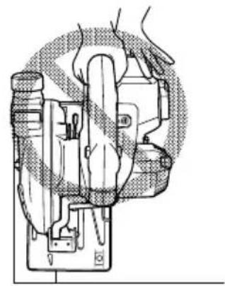
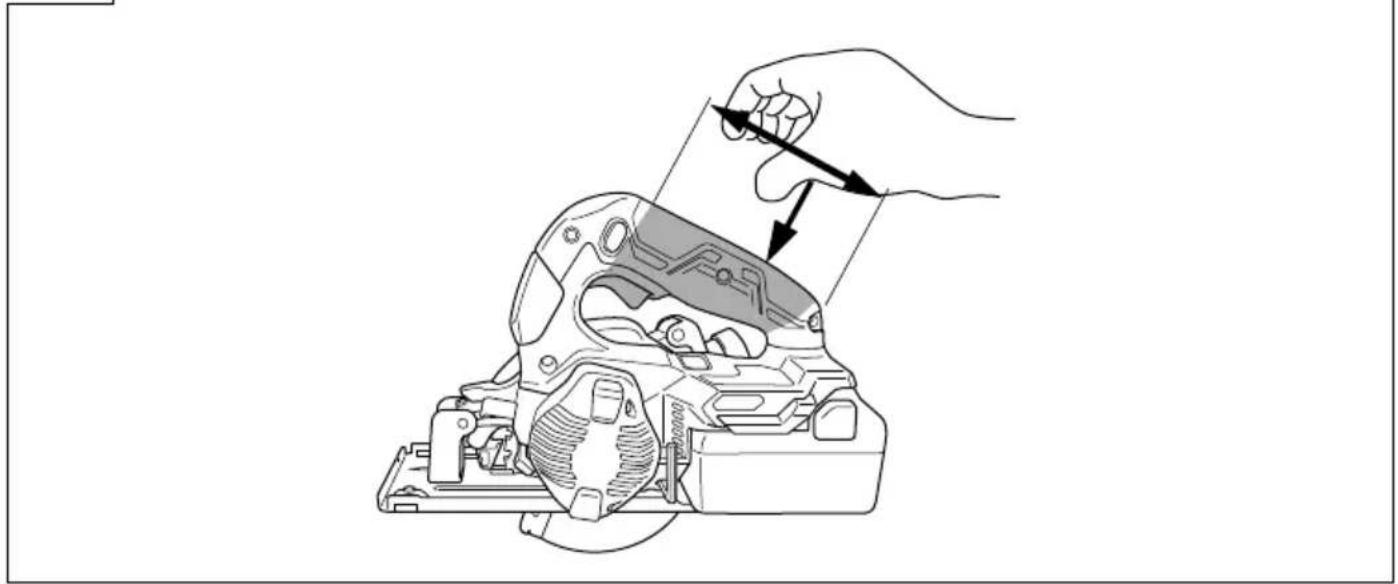
NEVER place your hand or fingers behind the saw (Fig. 4). If kickback occurs, the saw could easily jump backwards over your hand, possibly causing severe injury. - WARNING: It is important to support the work piece properly and to hold the saw firmly to prevent loss of control which could cause personal injury. Fig. 5 illustrates typical hand support of the saw.
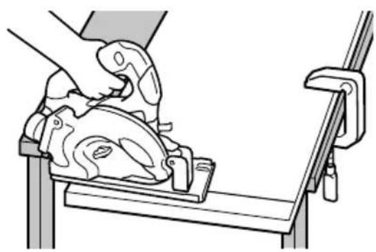
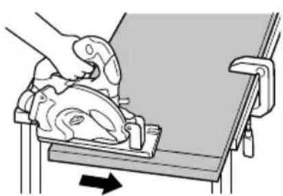
- Place the wider portion of the saw base on that part of the work piece which is solidly supported, not on the section that will fall off when the cut is made. As examples, Fig. 6 illustrates the RIGHT way to cut off the end of board, and Fig. 7 the WRONG way. If the work piece is short or small, clamp is down.
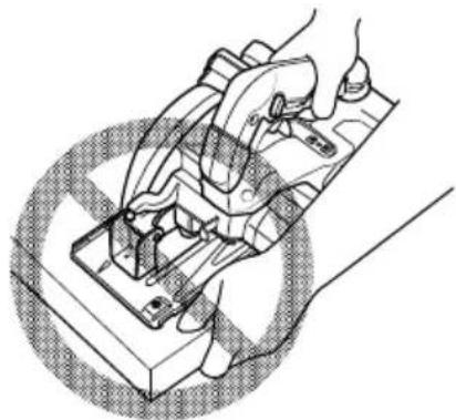
DON'T TRY TO HOLD SHORT PLACES BY HAND! - Never attempt to saw with the circular saw held upside down in a vise. This is extremely dangerous and can lead to serious accidents (Fig. 8).
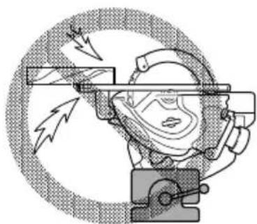
- Should lever remain loosened, it will create a very hazardous situation. Always thoroughly clamp it. (Fig. 9)
- Prior to cutting operation, make sure the material you are going to cut. If the material to be cut is expected to generate harmful / toxic dusts, make sure the dust bag or appropriate dust extraction system is connected with dust outlet tightly.
English
Wear the dust mask additionally, if available.
Before starting to saw, confirm that the saw blade has attained full-speed revolution.
- Should the saw blade stop or make an abnormal noise while operating, promptly turn OFF the switch.
○ Using the circular saw with the saw blade facing upwards or sideways is very hazardous. Such uncommon applications should be avoided.
- When cutting materials, always wear protective glasses.
○ When finished with a job, pull out the battery.
-
After having attached the saw blade, reconfirm that the lock lever is firmly secured in the prescribed position.
-
Do not expose directly your eye to the light by looking into the light.
If your eye is continuously exposed to the light, your eye will be hurt.
- Do not use the product if the tool or the battery terminals (battery mount) are deformed.
Installing the battery could cause a short circuit that could result in smoke emission or ignition.
- Keep the tool's terminals (battery mount) free of swarf and dust.
- Prior to use, make sure that swarf and dust have not collected in the area of the terminals.
During use, try to avoid swarf or dust on the tool from falling on the battery.
When suspending operation or after use, do not leave the tool in an area where it may be exposed to falling swarf or dust.
Doing so could cause a short circuit that could result in smoke emission or ignition.
-
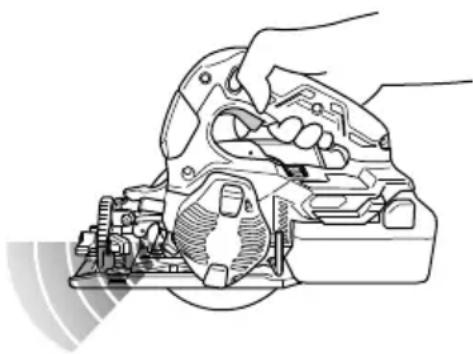
Always hold the tool firmly with one hand on handle. (Fig. 19)
-
Always use the tool and battery at temperatures between -5^ and 40^ .
-
Use a saw blade that suits each different cutting material.
-
Use a saw blade with a displayed speed that is equal to or higher than the rotation speed displayed on the tool.
CAUTION ON LITHIUM-ION BATTERY
To extend the lifetime, the lithium-ion battery equips with the protection function to stop the output.
In the cases of 1 to 3 described below, when using this product, even if you are pulling the switch, the motor may stop. This is not the trouble but the result of protection function.
- When the battery power remaining runs out, the motor stops.
In such a case, charge it up immediately.
-
If the tool is overloaded, the motor may stop. In this case, release the switch of tool and eliminate causes of overloading. After that, you can use it again.
-
If the battery is overheated under overload work, the battery power may stop.
In this case, stop using the battery and let the battery cool. After that, you can use it again.
Furthermore, please heed the following warning and caution.
WARNING
In order to prevent any battery leakage, heat generation, smoke emission, explosion and ignition beforehand, please be sure to heed the following precautions.
- Make sure that swarf and dust do not collect on the battery.
During work make sure that swarf and dust do not fall on the battery.
○ Make sure that any swarf and dust falling on the power tool during work do not collect on the battery.
- Do not store an unused battery in a location exposed to swarf and dust.
Before storing a battery, remove any swarf and dust that may adhere to it and do not store it together with metal parts (screws, nails, etc.).
2. Do not pierce battery with a sharp object such as a nail, strike with a hammer, step on, throw or subject the battery to severe physical shock.
3. Do not use an apparently damaged or deformed battery.
4. Do not use the battery in reverse polarity.
5. Do not connect directly to an electrical outlets or car cigarette lighter sockets.
6. Do not use the battery for a purpose other than those specified.
7. If the battery charging fails to complete even when a specified recharging time has elapsed, immediately stop further recharging.
8. Do not put or subject the battery to high temperatures or high pressure such as into a microwave oven, dryer, or high pressure container.
9. Keep away from fi re immediately when leakage or foul odor are detected.
10. Do not use in a location where strong static electricity generates.
11. If there is battery leakage, foul odor, heat generated, discolored or deformed, or in any way appears abnormal during use, recharging or storage, immediately remove it from the equipment or battery charger, and stop use.
12. Do not immerse the battery or allow any fluids to flow inside. Conductive liquid ingress, such as water, can cause damage resulting in fire or explosion. Store your battery in a cool, dry place, away from combustible and fl ammable items. Corrosive gas atmospheres must be avoided.
CAUTION
-
If liquid leaking from the battery gets into your eyes, do not rub your eyes and wash them well with fresh clean water such as tap water and contact a doctor immediately.
If left untreated, the liquid may cause eye-problems. -
If liquid leaks onto your skin or clothes, wash well with clean water such as tap water immediately.
There is a possibility that this can cause skin irritation.
- If you find rust, foul odor, overheating, discolor, deformation, and/or other irregularities when using the battery for the first time, do not use and return it to your supplier or vendor.
WARNING
If a conductive foreign matter enters in the terminal of lithium ion battery, the battery may be shorted, causing fire. When storing the lithium ion battery, obey surely the rules of following contents.
○ Do not place conductive debris, nail and wires such as iron wire and copper wire in the storage case.
To prevent shorting from occurring, load the battery in the tool or insert securely the battery cover for storing until the ventilator is not seen.
REGARDING LITHIUM-ION BATTERY TRANSPORTATION
When transporting a lithium-ion battery, please observe the following precautions.
WARNING
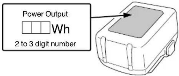
Notify the transporting company that a package contains a lithium-ion battery, inform the company of its power output and follow the instructions of the transportation company when arranging transport.
☐ Lithium-ion batteries that exceed a power output of 100 Wh are considered to be in the freight classification of Dangerous Goods and will require special application procedures.
For transportation abroad, you must comply with international law and the rules and regulations of the destination country.
USB DEVICE CONNECTION PRECAUTIONS (ONLY WITH UC18YSL3 CHARGER)
When an unexpected problem occurs, the data in a USB device connected to this product may be corrupted or lost. Always make sure to back up any data contained in the USB device prior to use with this product.
Please be aware that our company accepts absolutely no responsibility for any data stored in a USB device that is corrupted or lost, nor for any damage that may occur to a connected device.
WARNING
○ Prior to use, check the connecting USB cable for any defect or damage.
Using a defective or damaged USB cable can cause smoke emission or ignition.
When the product is not being used, cover the USB port with the rubber cover.
Buildup of dust etc. in the USB port can cause smoke emission or ignition.
NOTE
○ There may be an occasional pause during USB recharging.
When a USB device is not being charged, remove the USB device from the charger.
Failure to do so may not only reduce the battery life of a USB device, but may also result in unexpected accidents.
- It may not be possible to charge some USB devices, depending on the type of device.
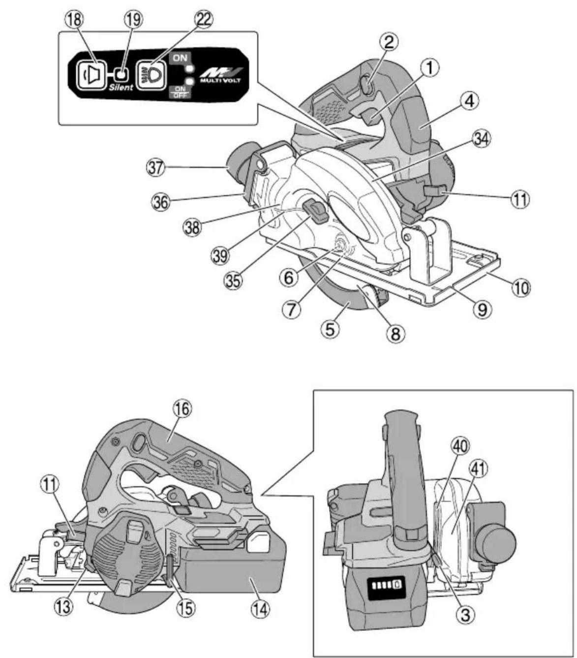
NAMES OF PARTS (Fig. 1 – Fig. 30)
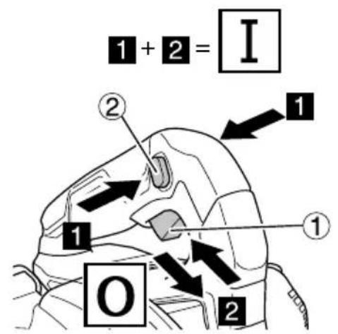
| 1 | Switch |
| 2 | Switch lock |
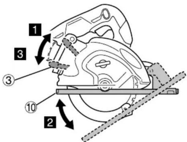
| 3 | Cutting depth lever |
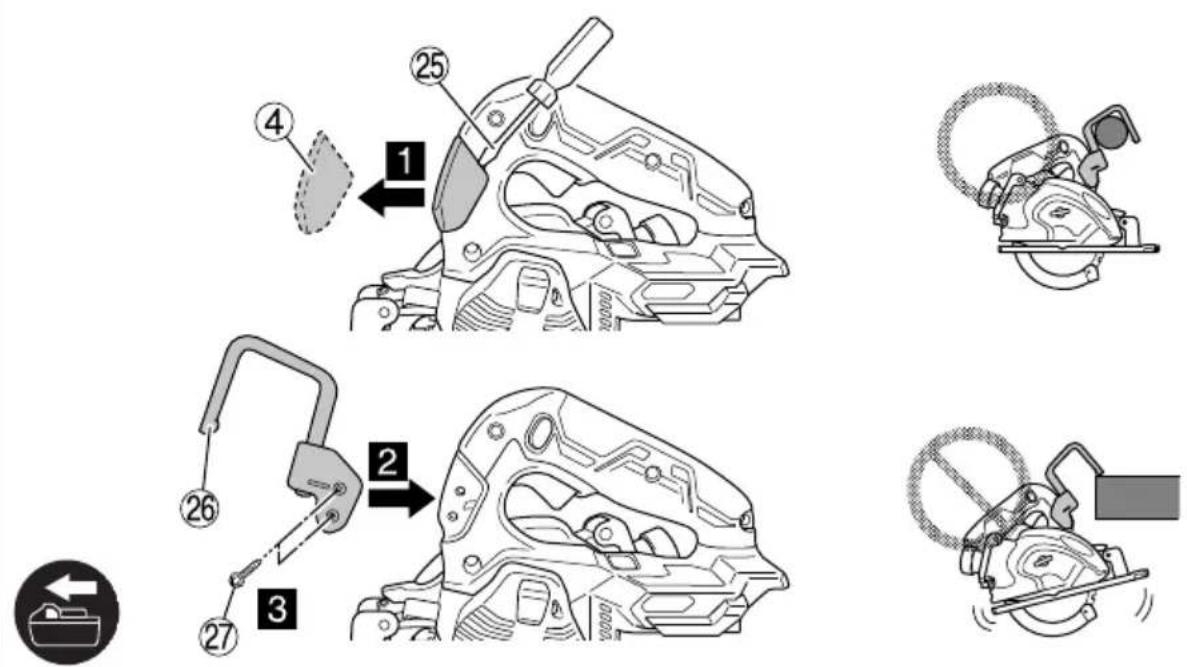
| 4 | Cover |
| 5 | Lower guard |
| 6 | Bolt |
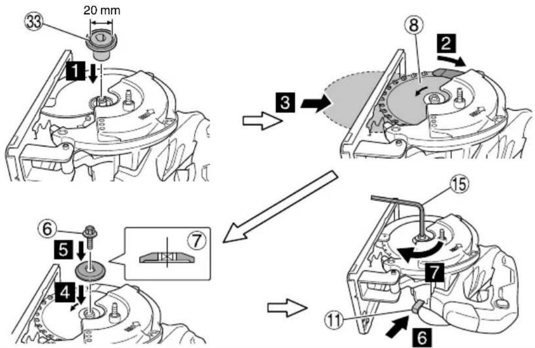
| 7 | Washer (B) |
| 8 | Saw blade |
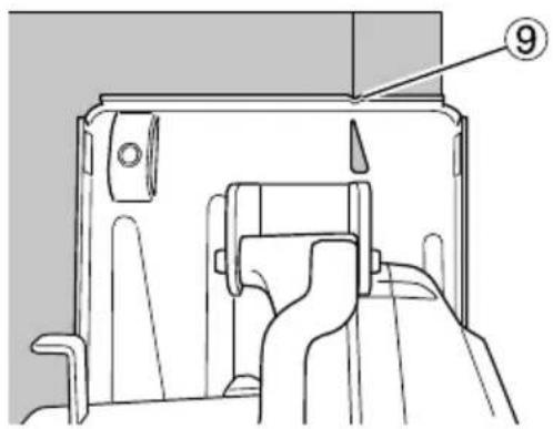
| 9 | Guide slit on the Base |
| 10 | Base |
| 11 | Lock lever |
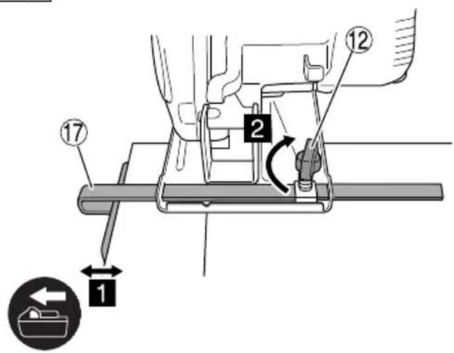
| 12 | Guide fastener wing bolt |
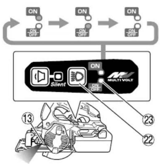
| 13 | LED light |
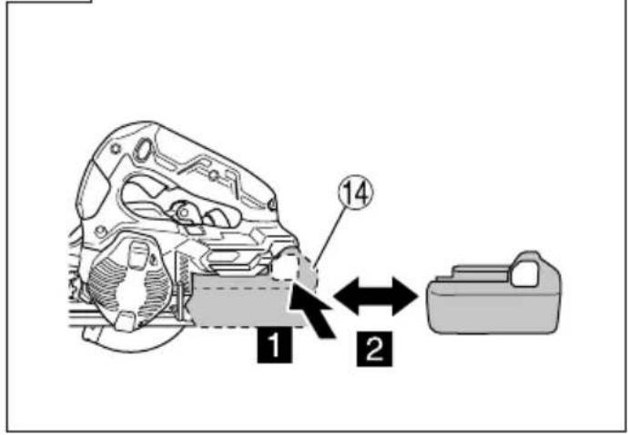
| 14 | Battery |
| 15 | Hex. bar wrench |
| 16 | Handle |
| 17 | Guide |
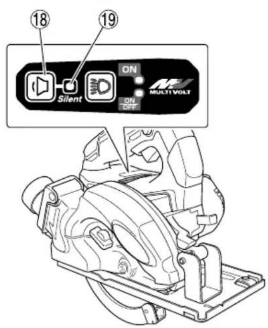
| 18 | Mode selector switch |
| 19 | Silent mode indicator lamp |
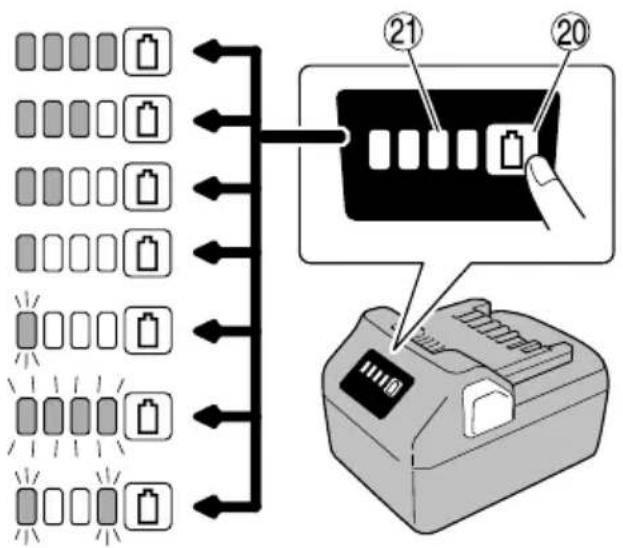
| 20 | Battery level indicator switch |
| 21 | Battery level indicator lamp |
| 22 | Lighting mode switch |
| 23 | Lighting mode indicator lamp |
| 24 | Phillips screwdriver |
| 25 | Flathead screwdriver |
| 26 | Hook |
| 27 | Screw |
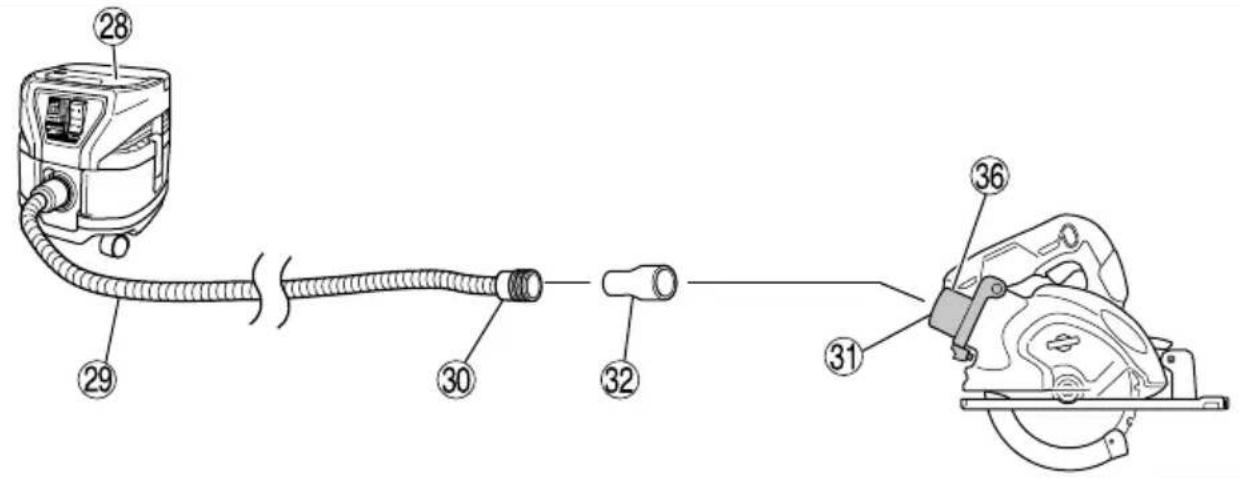
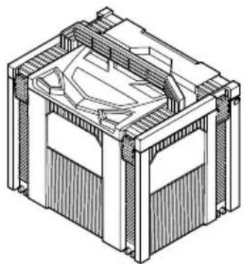
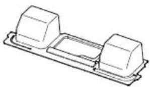
| 28 | Cleaner |
| 29 | Hose |
| 30 | Hose tip |
| 31 | Hose attachment port |
| 32 | Joint |
| 33 | Washer (A) |
| 34 | Saw cover (B) |
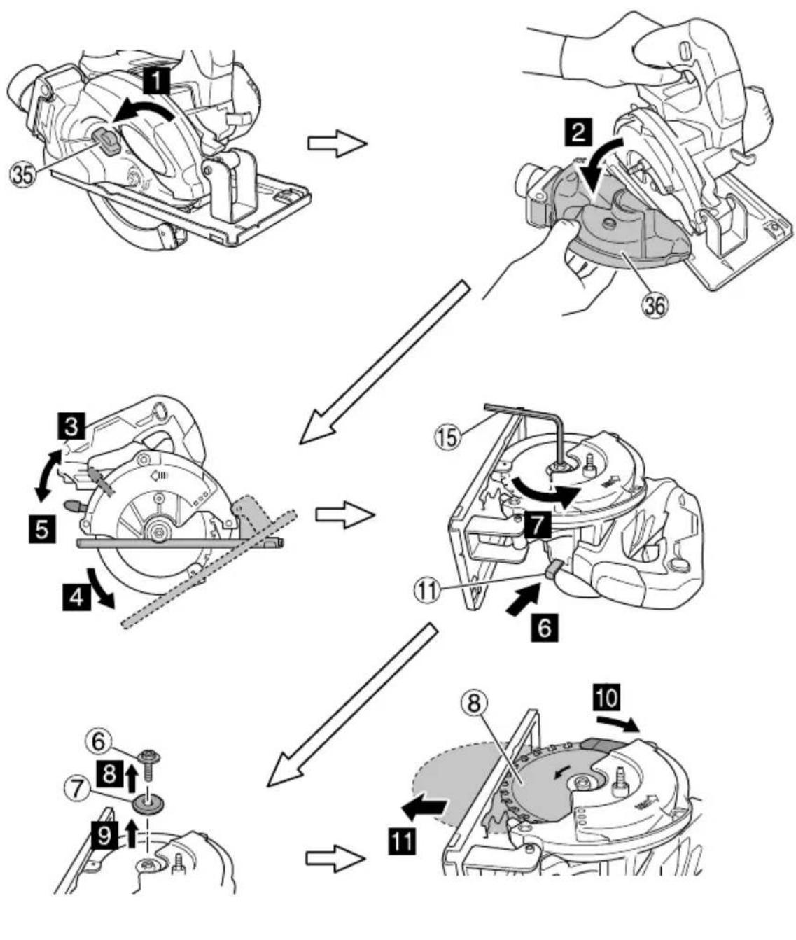
| 35 | Wing nut |
| 36 | Dust cover |
| 37 | Rubber cap |
| 38 | Saw cover (A) |
| 39 | Mark of saw cover (A) |
| 40 | Link |
| 41 | Gear cover |
SYMBOLS
WARNING
The following show symbols used for the machine. Be sure that you understand their meaning before use.
 | CD3605DA: Cordless Metal Cutting Saw |
 | To reduce the risk of injury, user must read instruction manual. |
 | Always wear eye protection. |
 | Always wear hearing protection. |
English
 | Only for EU countriesDo not dispose of electric tools together with household waste material!In observance of European Directive 2012/19/EU on waste electrical and electronic equipment and its implementation in accordance with national law, electric tools that have reached the end of their life must be collected separately and returned to an environmentally compatible recycling facility. |
| V Rated voltage | |
| n_0 | No-load speed |
| Switching ON | |
| Switching OFF | |
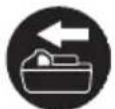
| Disconnect the battery | |
| Prohibited action | |
| Mode selector switch | |
| Lighting mode switch | |
| Always ON (turn off after 2 minute) | |
| Light only SW-ON | |
| Always OFF | |
| Remaining battery indicator switch | |
Battery
 | Lights;The battery remaining power is over 75% |
 | Lights;The battery remaining power is 50% – 75%. |
 | Lights;The battery remaining power is 25% – 50%. |
 | Lights;The battery remaining power is less than 25% |
 | Blinks;The battery remaining power is nearly empty.Recharge the battery soonest possible. |
 | Blinks;Output suspended due to high temperature.Remove the battery from the tool and allow it to fully cool down. |
 | Blinks;Output suspended due to failure or malfunction.The problem may be the battery so please contact your dealer. |
NOTE
To prevent the battery power consumption caused by forgetting to turn off the LED light, the light goes off automatically in about 2 minutes.
STANDARD ACCESSORIES
In addition to the main unit (1 unit), the package contains the accessories listed on page 313.
Standard accessories are subject to change without notice.
OPTIONAL ACCESSORIES (sold separately)
Carbide tipped saw blade
| Blade Tip width Number of teeth Code No. | ||||
| Standard accessories | For cutting soft steel materials 1.45 mm | 28 teeth 374352 | ||
| Optional accessories | For cutting stainless steel materials 1.15 mm | 42 teeth 3751 | 71 | |
| For cutting wood materials 1.2 mm | 24 teeth 374351 | |||
APPLICATIONS
| Blades | Uses | |
| Standard accessories | For cutting soft steel materials* | O For cutting various types of soft steel materials such as steel pipe, steel channels ("C" channels, "L" angles etc.) and aluminum sash.Cannot be used for cutting tempered steel materials. |
| Optional accessories | For cutting stainless steel materials | O For cutting stainless steel materials such as round pipes, etc. |
| For cutting wood materials | O For cutting various type of wood materials. |
* It is possible to cut aluminum. However, when doing so, apply cutting oil to the edge of the blade.
Optional accessories are subject to change without notice.
CAUTION
○ Do not connect with a cleaner when cutting steel materials.
○ Empty the inside of the saw cover when changing the materials to be cut.
○ Do not consecutively cut metal plates.
SPECIFICATIONS
1. Power tool
| Model CD3605DA | |||
| Voltage 36 V | |||
| No-Load Speed | 3600 min ^-1 (Power mode)2400 min ^-1 (Silent mode) | ||
| Capacity | Cutting depth | 90° | 46 mm |
| Battery available for this tool* | Multi volt battery | ||
| Weight** | 2.8 kg (BSL36A18X)3.1 kg (BSL36B18X) | ||
* Existing batteries (BSL3660/3620/3626, BSL18xx series, etc.) cannot be used with this tool.
** According to EPTA-Procedure 01/2014
NOTE
Due to HiKOKI's continuing program of research and development, the specifications herein are subject to change without prior notice.
Electronic control
○ Soft-start
○ Overload protection
This protection feature cuts off the power to the motor in the event of overloading of motor or a conspicuous reduction in rotational speed during operation.
When the overload protection feature has been activated, the motor may stop.
In this case, release the tool switch and eliminate causes of overloading.
After that you can use it again.
○ Overheat protection
This protection feature cuts off the power to the motor and stops the power tool in the event of overheating of motor during operation.
When the overheat protection feature has been activated, the motor may stop.
In this case, release the tool switch and cool it down in a few minutes.
After that you can use it again.
○ Continual heavy load protection
This protection function can result in a rotation decline when a continuous heavy load is applied. Should the heavy load continue, the motor may cease to operate.
○ Rotation speed changeover function (Power mode / Silent mode)
(Power mode / Silent mode switch function)
Each press of the Mode Selector Switch changes the operating mode. (Fig. 12)
Silent mode reduces maximum motor RPM enabling efficient work with less noise.
The Silent Mode Indicator Lamp lights in Silent mode.
When the load increases during Silent mode, the tool will automatically switch to Power mode and revert back to Silent mode when the load decreases.
In Power mode, no change is made to Silent mode even when the load decreases.
NOTE
-
To enable mode changes, pull the switch once after installing the battery.
○ Do not give a strong shock to the switch panel or break it. It may lead to a trouble. -
Battery
| Model | BSL36A18X |
| Voltage | 36 V / 18 V (Automatic Switching*) |
| Battery capacity | 2.5 Ah / 5.0 Ah(Automatic Switching*) |
| Available cordless products** | Multi volt series, 18 V product |
| Available charger | Sliding charger for lithium ion batteries |
* The tool itself will automatically switch over.
** Please see our general catalogue for details.
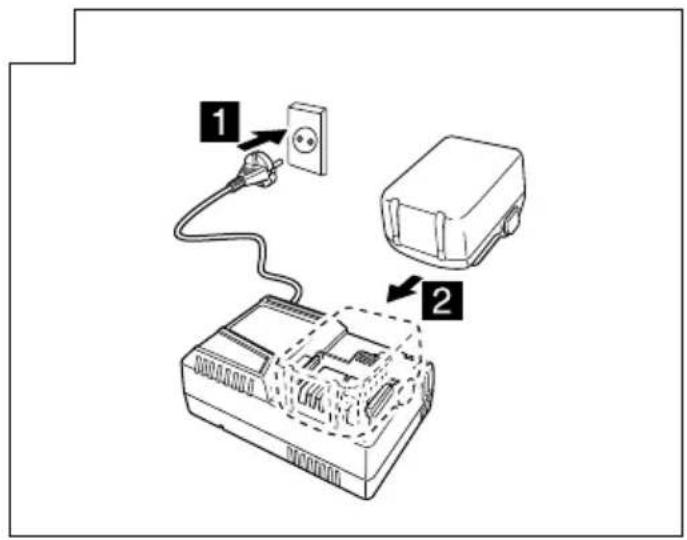
CHARGING
Before using the power tool, charge the battery as follows.
1. Connect the charger's power cord to the receptacle.
When connecting the plug of the charger to a receptacle, the charge indicator lamp will blink in red (At 1-second intervals).
2. Insert the battery into the charger.
Firmly insert the battery into the charger as shown in Fig. 18 (on page 5).
3. Charging
When inserting a battery in the charger, the charge indicator lamp will blink in blue.
When the battery becomes fully recharged, the charge indicator lamp will light up in green. (See Table 1)
(1) Charge indicator lamp indication
The indications of the charge indicator lamp will be as shown in Table 1, according to the condition of the
English
charger or the rechargeable battery.
Table 1
| Indications of the charge indicator lamp | ||||
| Charge indicator lamp (RED / BLUE / GREEN / PURPLE) | Before charging | Blinks (RED) | Lights for 0.5 seconds. Does not light for 0.5 seconds. (off for 0.5 seconds) | Plugged into power source |
| While charging | Blinks (BLUE) | Lights for 0.5 seconds. Does not light for 1 second. (off for 1 second) | Battery capacity at less than 50% | |
| Blinks (BLUE) | Lights for 1 second. Does not light for 0.5 seconds. (off for 0.5 seconds) | Battery capacity at less than 80% | ||
| Lights (BLUE) | Lights continuously | Battery capacity at more than 80% | ||
| Charging complete | Lights (GREEN) | Lights continuously(Continuous buzzer sound: about 6 seconds) | ||
| Overheat standby | Blinks (RED) | Lights for 0.3 seconds. Does not light for 0.3 seconds. (off for 0.3 seconds) | Battery overheated. Unable to charge. (Charging will commence when battery cools) | |
| Charging impossible | Flickers (PURPLE) | Lights for 0.1 seconds. Does not light for 0.1 seconds. (off for 0.1 seconds)(Intermittent buzzer sound: about 2 seconds) | Malfunction in the battery or the charger | |
(2) Regarding the temperatures and charging time of the rechargeable battery The temperatures and charging time will become as shown in Table 2.
Table 2
| Charger | UC18YSL3 | |||||||
| Battery | Type of battery | Li-ion | ||||||
| Temperatures at which the battery can be recharged | 0°C - 50°C | |||||||
| Charging voltage V | 14.4 18 | |||||||
| Charging time, approx. (At 20°C) | BSL14xx series BSL18xx series Multi volt series | |||||||
| (4 cells) | (8 cells) | (5 cells) | (10 cells) (10 cells) | |||||
| min. | BSL1415S :15BSL1415 :15BSL1415X :15BSL1420 :20BSL1425 :25BSL1430C :30 | BSL1430 :20BSL1440 :26BSL1450 :32BSL1460 :38 | BSL1815S :15BSL1815 :15BSL1815X :15BSL1820 :20BSL1825 :25BSL1830C :30 | BSL1830 :20BSL1840 :26BSL1850 :32BSL1860 :38 | BSL36A18 :32BSL36A18X :32BSL36B18 :52BSL36B18X :52 | |||
| USB | Charging voltage V | 5 | ||||||
| Charging current A | 2 | |||||||
NOTE
The recharging time may vary according to the ambient temperature and power source voltage.
-
Disconnect the charger's power cord from the receptacle.
-
Hold the charger firmly and pull out the battery. NOTE
Be sure to pull out the battery from the charger after use, and then keep it.
Regarding electric discharge in case of new batteries, etc.
As the internal chemical substance of new batteries and batteries that have not been used for an extended period is not activated, the electric discharge might be low when
using them the first and second time. This is a temporary phenomenon, and normal time required for recharging will be restored by recharging the batteries 2 – 3 times.
How to make the batteries perform longer.
(1) Recharge the batteries before they become completely exhausted.
When you feel that the power of the tool becomes weaker, stop using the tool and recharge its battery. If you continue to use the tool and exhaust the electric current, the battery may be damaged and its life will become shorter.
(2) Avoid recharging at high temperatures.
A rechargeable battery will be hot immediately after use. If such a battery is recharged immediately after use, its internal chemical substance will deteriorate, and the battery life will be shortened. Leave the battery and recharge it after it has cooled for a while.
CAUTION
☐ If the battery is charged while it is heated because it has been left for a long time in a location subject to direct sunlight or because the battery has just been used, the charge indicator lamp of the charger lights for 0.3 seconds, does not light for 0.3 seconds (off for 0.3 seconds). In such a case, first let the battery cool, then start charging.
When the charge indicator lamp flickers (at 0.2-second intervals), check for and take out any foreign objects in the charger's battery connector. If there are no foreign objects, it is probable that the battery or charger is malfunctioning. Take it to your authorized Service Center.
○ Since the built-in micro computer takes about 3 seconds to confirm that the battery being charged with UC18YSL3 is taken out, wait for a minimum of 3 seconds before reinserting it to continue charging. If the battery is reinserted within 3 seconds, the battery may not be properly charged.
MOUNTING AND OPERATION
| Action Figure Page | ||
| Adjusting the cutting depth 9 3 | ||
| Cutting line 10 3 | ||
| Switch operation 11 4 | ||
| About the mode select function (*1) | 12 | 4 |
| Remaining battery indicator | 13 4 | |
| Using the LED light | 14 4 | |
| Attaching the guide (sold separately) | 15 4 | |
| Attaching the hook (*2)(sold separately) | 16 | 5 |
| Removing and inserting the battery | 17 5 | |
| Charging | 18 5 | |
| Holding the tool | 19 5 | |
| Connection with cleaner(sold separately) | 20 | 6 |
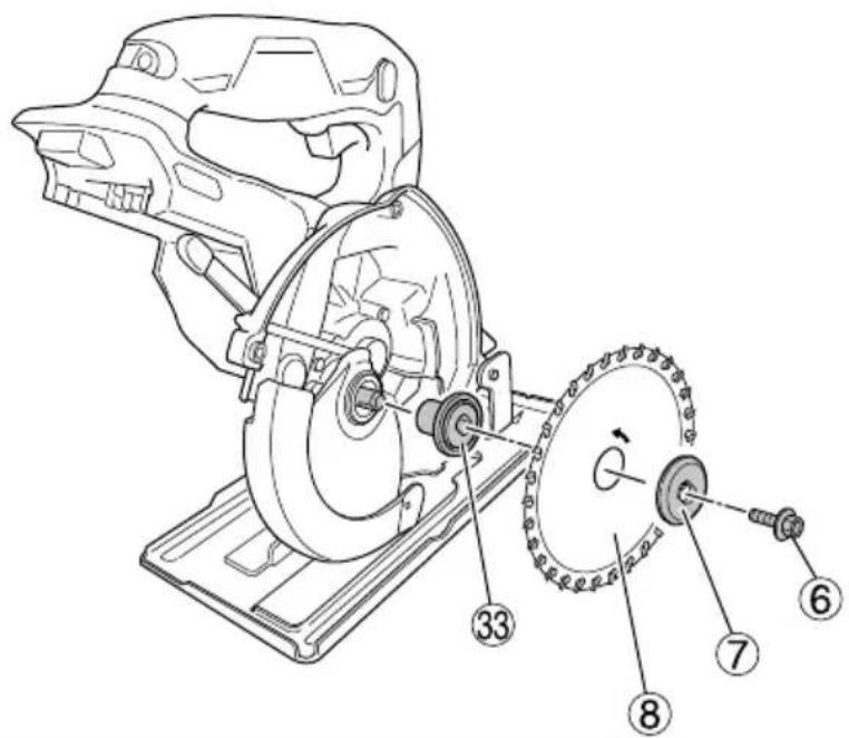
| Dismounting the saw blade | 21 6 | |
| Mounting the saw blade (*3) | 22 | 7 |
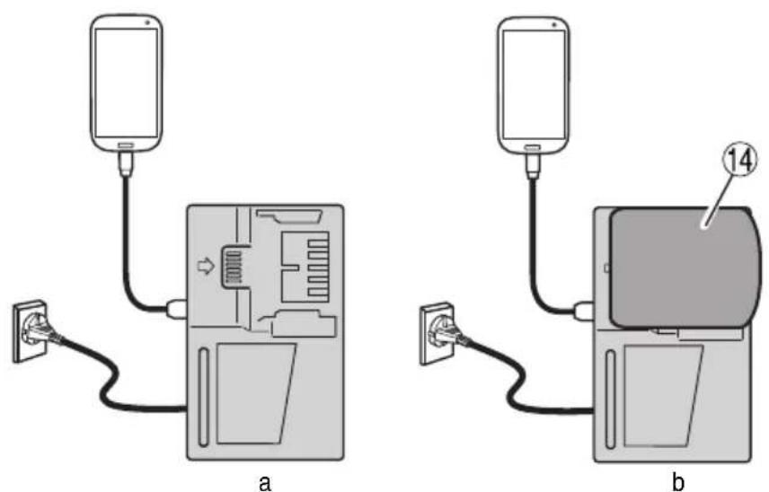
| Charging a USB device from aelectrical outlet | 23-a | 7 |
| Charging a USB device and batteryfrom a electrical outlet | 23-b | 7 |
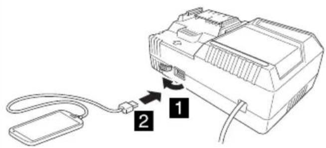
| How to recharge USB device | 24 7 | |
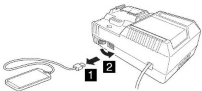
| When charging of USB device iscompleted | 25 | 7 |
| Selecting accessories | — | 314 |
(\*1) About the mode select function
Each time the mode selector switch is pushed, the operation mode changes.
When Silent mode is selected, the Silent mode indicator lamp lights up.
Silent mode reduces maximum motor RPM enabling efficient work with less noise.
If the load increases while the motor is operating in Silent mode, it automatically changes to Power mode. Additionally, if the load decreases again, it automatically returns to Silent mode.
With power mode, the protection function activates to reduce the number of revolutions whenever the unit is continuously burdened with a heavy load.
| Mode | No-load speed |
| Power | 3600 min ^-1 |
| Silent | 2400 min ^-1 |
NOTE
○ The mode will only change after a battery is installed and the switch is pulled once.
☐ The current mode will be maintained even if the switch is on/off, or the battery is removed/reinserted.
(\*2) Attaching the Hook
The hook can be used to hang up the unit temporarily during operations (Fig. 16).
CAUTION
The hook should never be used to hang the unit on your person.
When using the hook, check to make sure that the main unit will not slip and fall, or become unstable by the wind, etc.
Never hang the unit from your belt or trousers as this could cause accidents.
(\*3)
After using the tipped saw blade, saw covers (A) and (B) may become hot. Take caution when handling.
LED LIGHT WARNING SIGNALS (Fig. 31)
This product features functions that are designed to protect the tool itself as well as the battery. While the switch is pulled, if any of the safeguard functions are triggered during operation, the LED light will blink as described in Table 3. When any of the safeguard functions are triggered, follow the instructions described under corrective action.
natural_image
Line drawing of a hand operating a mechanical device with gears and levers (no text or symbols)Fig. 31
Table 3
| Protective Function | Overheat Protection Overload Protection Continual | Heavy loadProtection 1 | Continual Heavy loadProtection 2 | |
| Tool Status Motor stopped during operation | Motor stopped during operation | Motor speed declined during operation | Motor stopped during operation | |
| LED Lighting Status | 0.5 second | 0.1 second Depend | ds on the type of LED light warning signal in use. | 0.1 second |
| Lighting Condition of the Display Lamp | Power mode: Light OFF Silent mode: Light ON | Power mode: Light OFF Silent mode: Light ON | 0.5 second 0.1 second | cond |
| Cause Motor at high temperature | Motor is overloaded Motor is continuously overloaded | Continued operation despite Continual Heavy load Protection 1 warning | ||
| Countermeasure Allow the unit to fully cool down.LED blinking should stop approximately 10 seconds after releasing the switch. | Remove the cause of the overload.LED blinking should stop approximately 10 seconds after releasing the switch. | If further overload continues over a long period of time, Continual Heavy load Protection 2 will be triggered, and the unit will stop operation.Press the mode selector switch approximately 10 seconds after releasing the switch to cancel the fl ashing and return to Power mode display lamp. | Remove the cause of the overload and allow the unit to cool down.Press the mode selector switch approximately 2 minutes after releasing the switch to cancel the fl ashing of the LED light and display lamp.Continue operation. | |
DISPOSING CHIPS
WARNING
When disposing chips, make sure that the tool is switched off and that the battery is removed.
CAUTION
○ When cutting steel materials, make sure to empty the waste material when the cuttings reach the mark. (Fig. 26)
The heat of the cuttings may deform the saw cover.
○ Depending on the material being cut, the waste material may retain heat. Do not touch the waste material or the saw cover (A) and (B) with your bare hands.
NOTE
○ Collecting efficiency will decrease if the tool is used when the saw cover's interior is full of chips.
Make sure to dispose the chips before the interior of the saw cover is full.
○ When disposing the chips, be careful not to spill the chips into the motor or the battery mount.
○ Empty the inside of the saw cover when changing the materials to be cut.
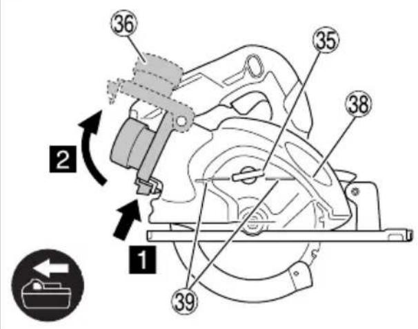
(1) Press the hook below the dust cover, open the dust cover and dispose the chips inside the saw cover. (Fig. 26)
(2) Close the dust cover and secure it with the hook.
OR
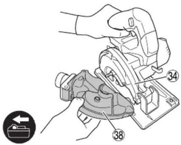
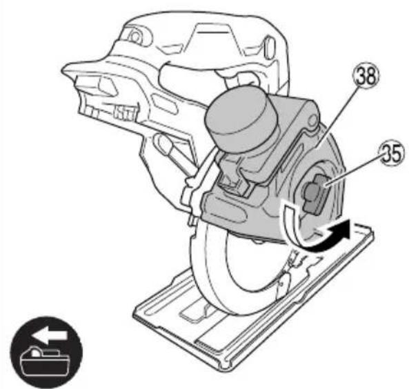
(1) Point the saw cover downwards, loosen the wing nut, remove saw cover (A) and dispose the chips collected inside the saw cover. (Fig. 27)
(2) Attach the saw cover (A) and secure it with the wing nut.
NOTE
If any sawdust or other particles have collected on the inside of the saw cover (B), please see page 18 "Cleaning the interior of the saw cover".
MAINTENANCE AND INSPECTION
1. Inspecting the saw blade
Since use of as dull saw blade will degrade efficiency and cause possible motor malfunction, sharpen or replace the saw blade as soon as abrasion is noted.
2. Inspecting the mounting screws
Regularly inspect all mounting screws and ensure that they are properly tightened. Should any of the screws be loose, retighten them immediately. Failure to do so could result in serious hazard.
3. Motor unit maintenance
The motor winding is an important part of this tool. Avoid damaging and be careful to avoid contact with cleaning oil or water.
Dust or particle accumulation in the motor can result in damage.
4. Inspecting and maintaining the lower guard
Always make sure that the lower guard moves smoothly. In the event of any malfunction, immediately repair the lower guard.
5. Cleaning the interior of the saw cover
Periodically check and clean to ensure that the saw cover is clean of sawdust or other particles.
(1) Loosen the wing nut and remove the saw cover (A). (Fig. 28)
NOTE
Depending on the shape of the saw blade being used, the saw cover (B) cannot be removed. If this is the case, reverse the order of the instructions for (2) and (3).
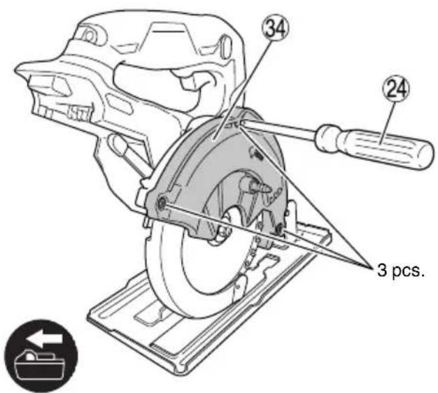
(2) Loosen the three screws with a Phillips head screwdriver and remove saw cover (B). (Fig. 29)
(3) Remove the saw blade according to the instructions listed under page 17 "Dismounting the saw blade".
(4) Remove chips from the inside of the saw cover, spindle, washer and other areas. (Fig. 30)
(5) Reassemble in the reverse order, being careful of the facings for the washer, saw blade and other parts. (Fig. 30)
6. Inspection of terminals (tool and battery)
Check to make sure that swarf and dust have not collected on the terminals.
On occasion check prior, during and after operation.
CAUTION
Remove any swarf or dust which may have collected on the terminals.
Failure to do so may result in malfunction.
7. Cleaning on the outside
When the power tool is stained, wipe with a soft dry cloth or a cloth moistened with soapy water. Do not use chloric solvents, gasoline or paint thinner, for they melt plastics.
8. Storage
Store the power tool and battery in a place in which the temperature is less than 40^ C and out of reach of children.
NOTE
Storing lithium-ion batteries.
Make sure the lithium-ion batteries have been fully charged before storing them.
Prolonged storage (3 months or more) of batteries with a low charge may result in performance deterioration, signifi cantly reducing battery usage time or rendering the batteries incapable of holding a charge.
However, signifi cantly reduced battery usage time may be recovered by repeatedly charging and using the batteries two to fi ve times.
If the battery usage time is extremely short despite repeated charging and use, consider the batteries dead and purchase new batteries.
CAUTION
In the operation and maintenance of power tools, the safety regulations and standards prescribed in each country must be observed.
Important notice on the batteries for the HiKOKI cordless power tools
Please always use one of our designated genuine batteries. We cannot guarantee the safety and performance of our cordless power tool when used with batteries other than these designated by us, or when the battery is disassembled and modified (such as disassembly and replacement of cells or other internal parts).
GUARANTEE
We guarantee HiKOKI Power Tools in accordance with statutory/country specific regulation. This guarantee does not cover defects or damage due to misuse, abuse, or normal wear and tear. In case of complaint, please send the Power Tool, undismantled, with the GUARANTEE CERTIFICATE found at the end of this Handling instruction, to a HiKOKI Authorized Service Center.
Information concerning airborne noise and vibration
The measured values were determined according to EN62841 and declared in accordance with ISO 4871.
Measured A-weighted sound power level: 114 dB (A)
Measured A-weighted sound pressure level: 106 dB (A)
Uncertainty K: 3 dB (A).
Wear hearing protection.
Vibration total values (triax vector sum) determined according to EN62841.
Cutting metal:
Vibration emission value a_h=2.1 m/s^2
Uncertainty K = 1.5 m/s²
The declared vibration total value and the declared noise emission value have been measured in accordance with a standard test method and may be used for comparing one tool with another.
They may also be used in a preliminary assessment of exposure.
WARNING
The vibration and noise emission during actual use of the power tool can differ from the declared total value depending on the ways in which the tool is used especially what kind of workpiece is processed; and
- Identify safety measures to protect the operator that are based on an estimation of exposure in the actual conditions of use (taking account of all parts of the operating cycle such as the times when the tool is switched off and when it is running idle in addition to the trigger time).
NOTE
Due to HiKOKI's continuing program of research and development, the specifications herein are subject to change without prior notice.
TROUBLESHOOTING
Use the inspections in the table below if the tool does not operate normally. If this does not remedy the problem, consult your dealer or the HiKOKI Authorized Service Center.
- Power tool
| Symptom Possible | cause Remedy | |
| Tool doesn’t run No remaining | g battery power Charge the battery. | |
| Battery isn’t fully installed. Push the battery in | until you hear a click. | |
| Tool suddenly stopped Motor | is overloaded Get rid of the problem causing | theoverloaded. |
| Overload protection is in operation. | ||
| The battery is overheated. Let the battery cool | down. | |
| Suddenly stopped Motor was | continuously overloaded. Refer to “LED LIGHT WARNING SIGNALS”. | |
| Motor speed declined during operation | Motor was continuously overloaded. Refer to “LED LIGHT WARNING SIGNALS”. | |
| Doesn’t cut well The saw blade | de is worn or missing teeth. Replace with a new saw blade. | |
| The bolt is loose. Firmly tighten the bolt. | ||
| The saw blade is installed backwards. Install the saw blade in the proper direction. | ||
| Switch can’t be pulled The switch lock is not pushed in enough. Push the switch lock in all the way. | ||
| Sawdust discharge is poor | Sawdust has accumulated in the saw cover. | Remove the sawdust inside the saw cover. |
| Battery cannot be installed | Attempting to install a battery other than that specified for the tool. | Please install a multi volt type battery. |
- Charger
| Symptom Possible | cause Remedy | |
| The charge indicator lamp is rapidly fl ickers purple, and battery charging doesn't begin. | The battery is not inserted all the way. | Insert the battery firmly. |
| There is foreign matter in the battery terminal or where the battery is attached. | Remove the foreign matter. | |
| The charge indicator lamp blinks red, and battery charging doesn't begin. | The battery is not inserted all the way. | Insert the battery firmly. |
| The battery is overheated. If left alone, the battery will automatically begin charging if its temperature decreases, but this may reduce battery life. It is recommended that the battery be cooled in a well-ventilated location away from direct sunlight before charging it. | ||
| Battery usage time is short even though the battery is fully charged. | The battery's life is depleted. Replace the battery with a new one. | |
| The battery takes a long time to charge. | The temperature of the battery, the charger, or the surrounding environment is extremely low. | Charge the battery indoors or in another warmer environment. |
| The charger's vents are blocked, causing its internal components to overheat. | Avoid blocking the vents. | |
| The cooling fan is not running. Contact a HiKO | OKI Authorized Service Center for repairs. | |
| The USB power lamp has switched off and the USB device has stopped charging. | The battery's capacity has become low. Replace the battery with one that has capacity remaining. | |
| USB power lamp does not switch off even though the USB device has fi nished charging. | The USB power lamp lights up green to indicate that USB charging is possible. | This is not a malfunction. |
| It is unclear what the charging status of a USB device is, or whether its charging is complete. | The USB power lamp does not switch off even when charging is complete. | Examine the USB device that is charging to confi rm its charging status. |
| Charging of a USB device pauses midway. | The charger was plugged into an electrical socket while the USB device was being charged using the battery as the power source. | This is not a malfunction.The charger pauses USB charging for about 5 seconds when it is dif erentiating between power sources. |
| A battery was inserted into the charger while the USB device was being charged using a power socket as the power source. | ||
| Charging of the USB device pauses midway when the battery and the USB device are being charged at the same time. | The battery has become fully charged. This is not a malfunction.The charger pauses USB charging for about 5 seconds while it checks whether the battery has successfully completed charging. | |
| Charging of the USB device doesn't start when the battery and the USB device are being charged at the same time. | The remaining battery capacity is extremely low. | This is not a malfunction.When the battery capacity reaches a certain level, USB charging automatically begins. |
ALLGEMEINE
natural_image
Line drawing of a hand using a power tool to adjust or install a mechanical component (no text or symbols present)Abb. 31
Tabelle 3
natural_image
Line drawing of a hand using a tool to cut or install a mechanical component (no text or symbols present)Fig. 31
Tableau 3
natural_image
Line drawing of a hand using a power tool to adjust or install a mechanical component (no text or symbols visible)Fig. 31
Tabella 3
VEILIGHEIDSWAARSCHUWINGEN DRAADLOZE METAALZAAG
VEILIGHEIDSWAARSCHUWINGEN
natural_image
Diagram of a mechanical housing or enclosure with a highlighted square component and two side tabs (no text or symbols)VOORZORGSMAATREGELEN AANSLUITING USB-APPARAAT (ALLEEN MET UC18YSL3 OPLADER)
natural_image
Line drawing of a hand using a pliers to cut or adjust a mechanical component (no text or symbols present)Afb. 31
Tabel 3
natural_image
Line drawing of a hand operating a mechanical device with no visible text or symbolsFig. 31
Tabla 3
natural_image
Line drawing of a hand using a tool to cut or adjust a mechanical component (no text or symbols present)Fig. 31
Tabela 3
natural_image
Line drawing of a hand using a tool to cut or adjust a mechanical component (no text or symbols present)Bild 31
Tabell 3
natural_image
Line drawing of a hand operating a mechanical device with no visible text or symbolsFig. 31
Tabel 3
○ Overopphetingsvern
natural_image
Line drawing of a hand using a pliers to cut or adjust a mechanical component (no text or symbols present)Fig. 31
Tabell 3
VEDLIKEHOLD OG INSPEKSJON
1. Inspisere sagbladet
natural_image
Line drawing of a hand using a power tool to cut or install a mechanical component (no text or symbols present)Kuva 31
Taulukko 3
natural_image
Line drawing of a hand using a pliers to cut or adjust internal components (no text or symbols)Eik. 31
Πίνακας 3
natural_image
Line drawing of a hand operating a mechanical device with gears and a handle (no text or symbols)Rys. 31
Tabela 3
natural_image
Line drawing of a hand using a pliers to cut or adjust internal components (no text or symbols)-
ábra
-
táblázat
natural_image
Line drawing of a hand using a pliers to adjust or install a mechanical component (no text or symbols visible)Obr. 31
Tabulka 3
natural_image
Line drawing of a hand using a mechanical tool to adjust or install a component (no text or symbols visible)Şek. 31
Tablo 3
natural_image
Line drawing of a hand operating a mechanical device with gears and a circular component (no text or symbols)Fig. 31
Tabelul 3
natural_image
Line drawing of a hand operating a mechanical device with gears and a handle (no text or symbols)SI. 31
Tabela 3
natural_image
Line drawing of a hand using a power tool to adjust or install a mechanical component (no text or symbols visible)Obr. 31
Tabul'ka 3
natural_image
Line drawing of a hand operating a mechanical device with gears and levers (no text or symbols)Фиг. 31
Таблица 3
natural_image
Line drawing of a hand using a tool to cut or adjust a mechanical component (no text or symbols present)Sl. 31
Tabela 3
| Zaštitna funkcija Zaštita od pregrevanja Zaštita od preopterećenja | Neprekidna zaštita od velikih opterećenja 1 | Neprekidna zaštita od velikih opterećenja 2 | ||
| Status alata Motor se zaustavio u toku rada | Motor se zaustavio u toku rada | Brzina motora je opala u toku rada | Motor se zaustavio u toku rada | |
| Status LED osvetljenja | 0,5 sekundi | 0,1 sekunda | Zavisi od vrste LED svetlosnog signala upozorenja koji se koristi. | 0,1 sekunda |
| Stanje osvetljenja lampe za prikaz | Režim napajanja: ISKLJUČENO svetlo Tihi režim: UKLJUČENO svetlo | Režim napajanja: ISKLJUČENO svetlo Tihi režim: UKLJUČENO svetlo | 0,5 sekundi | 0,1 sekunda |
| Uzrok Motor je na visokoj temperaturi | Motor je preopterećen | Motor je neprekidno preopterećen | Nastavljen rad uprkos upozorenju Neprekidne zaštite od velikih opterećenja 1 | |
| Suprotna mera Ostavite da se jedinica u potpunosti ohladi. LED treperenje treba da se zaustavi otprilike 10 sekunde nakon otpuštanja prekidača. | Uklonite uzrok preopterećenja. LED treperenje treba da se zaustavi otprilike 10 sekunde nakon otpuštanja prekidača. | Ako se dalje preopterećenje nastavi tokom dužeg vremenskog perioda, Neprekidna zaštita od velikih opterećenja 2 će se pokrenuti i jedinica će prestati da radi. Pritisnite prekidač za izbor režima na oko 2 minuta nakon otpuštanja prekidača za otkazivanje treperenja LED svetla i lampe prikaza. Nastavite sa radom. | Uklonite uzrok preopterećenja i dozvolite jedinici da se ohladi. Pritisnite prekidač za izbor režima na oko 2 minuta nakon otpuštanja prekidača za otkazivanje treperenja LED svetla i lampe prikaza. Nastavite sa radom. | |
ODLAGANJE IVERJA
UPOZORENJE
Prilikom odlaganja iverja, proverite da li je alat isključen i da li je baterija uklonjena.
OPREZ
Kada se seku čelični materijali, postarajte se da ispraznite otpadni materijal kada ostaci sečenja dođu do oznake. (SI. 26)
Toplota ostataka sečenja može da deformiše poklopac testere.
○ U zavisnosti od materijala koji se seče, otpadni materijal može da zadrži toplotu. Ne dodirujte otpadni materijal ili poklopac testere (A) i (B) golim rukama.
NAPOMENA
natural_image
Line drawing of a hand using a power tool to adjust or install a mechanical component (no text or symbols visible)Sl. 31
Tablica 3
natural_image
Line drawing of a battery pack with a digital display (no text or symbols)
natural_image
Line drawing of a mechanical component with internal slots and housing (no text or symbols)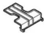
BSL36..18 329897UC18YSL3 (14,4V - 18V)
natural_image
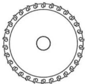
Circular mechanical component with evenly spaced teeth and central bore (no text or symbols)374352
374255

338917374254
944459

natural_image
Line drawing of a tool with a handle and a flat blade, no text or symbols present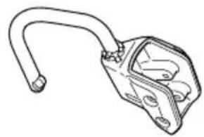
natural_image
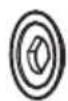
Line drawing of a mechanical clamp or bracket (no text or symbols)339187962175
natural_image
Technical line drawing of a mechanical housing or enclosure with internal components (no text or symbols)337528
natural_image
Technical line drawing of a mechanical component with two cylindrical parts mounted on a base plate (no text or symbols)375344
natural_image
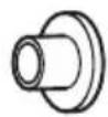
Technical line drawing of a mechanical housing or enclosure component (no text or symbols)375343
| English Dansk Română | ||||
| GUARANTEE CERTIFICATE1 Model No.2 Serial No.3 Date of Purchase4 Customer Name and Address5 Dealer Name and Address(Please stamp dealer name and address) | GARANTIBEVIS1 Modelnummer2 Seriennummer3 Købsdato4 Kundes navn og adresse5 Forhandlers navn og adresse(Indsæt stempel med forhandlers navn og adresse) | CERTIFICAT DE GARANTIE1 Model nr.2 Nr. de serie3 Data cumpărării4 Numele și adresa clientului5 Numele și adresa distribuitorului(Vă rugăm aplicați štampila cu numele și adresa distribuitorului) | ||
| Deutsch Norsk Slovenščina | ||||
| GARANTIESCHEIN1 Modell-Nr.2 Serien-Nr.3 Kaufdatum4 Name und Anschrift des Kunden5 Name und Anschrift des Händlers(Bitte mit Namen und Anschrift des Handlers abstempeln) | GARANTISERTIFIKAT1 Modellnr.2 Serienr.3 Kjøpsdato4 Kundens navn og adresse5 Forhandlerens navn og adresse(Vennligst stemple forhandlerens navn og adresse) | GARANCIJSKO POTRDILO1 Št. modela2 Serijska št.3 Datum nakupa4 Ime in naslov kupca5 Ime in naslov prodajalca(Prosimo vtsnite žig z imenom in naslovom prodajalca) | ||
| Français Suomi Slovenčina | ||||
| CERTIFICAT DE GARANTIE1 No. de modèle2 No de série3 Date d'achat4 Nom et adresse du client5 Nom et adresse du revendeur(Cachet portant le nom et l'adresse du revendeur) | TAKUUTODISTUS1 Malli nro2 Sarja nro3 Ostopăivămâără4 Asiakkaan nimi ja osoite5 Myyjän nimi ja osoite(Leimaa myyjän nimi ja osoite) | ZÁRUČNÝ LISTA1 Č. modelu2 Sériové č.3 Dátum zakúpenia4 Meno a adresa zákaznika5 Názov a adresa predajcu(Pečiatka s názvom a adresou predajcu) | ||
| Italiano Ελληνικά Български | ||||
| CERTIFICATO DI GARANZIA1 Modello2 N° di serie3 Data di acquisto4 Nome e indirizzo dell'acquirente5 Nome e indirizzo del rivenditore(Si prega di apporre il timbro con questi dati) | ПІЗТОПОІНТИКО ЕГГУНЄНЕ1 Ар. Мовтёлou2 Aúξων Αρ.3 Нμερομηνία αγοράς4 Όνομα και δεύθυνση πελάτη5 Όνομα και δεύθυνση μεταπωλητή(Παρακαλούμε να χρησιμοποιηθεί σφραγίδα) | ГАРАНЦИОНЕН СЕРТИФИКАТ1 Модел No2 Сериен No3 Дата за закупуване4 Име и адрес на клиента5 Име и адрес на търговеца(Моля, отпечатайте името и адрес на дильра) | ||
| Nederlands Polski Srpski | ||||
| GARANTIEBEWIJS1 Modelnummer2 Serienummer3 Datum van aankoop4 Naam en adres van de gebruiker5 Naam en adres van de handelaar(Stempel a.u.b. naam en adres vande de handelaar) | GWARANCJA1 Model2 Numer seryjny3 Data zakupu4 Nazwa klienta i adres5 Nazwa dealera i adres(Pieczęć punktu sprzedaży) | GARANTNI SERTIFIKAT1 Br. modela.2 Serijski br.3 Datum kupovine4 Ime i adresa kupca5 Ime i adresa prodavca(Molimo da stavite pečat na ime i adresu trgovca) | ||
| Español Magyar Hrvatski | ||||
| CERTIFICADO DE GARANTÍA1 Número de modelo2 Número de serie3 Fecha de adquisición4 Nombre y dirección del cliente5 Nombre y dirección del distribuidor(Se ruega poner el sello del distribuidor con su nombre y dirección) | GARANCIA BIZONYLAT1 Tipusszám2 Sorozatszám3 A vásárlás dátuma4 A Vásárló neve és címe5 A Kereskedő neve és címe(Kérjük ide elhelyezni a Kereskedő nevének és címének pecsétjét) | JAMSTVENI CERTIFIKAT1 Br modela.2 Serijski br.3 Datum kupnje4 Ime i adresa kupca5 Ime i adresa trgovca(Molimo stavite pečat na ime i adresu trgovca) | ||
| Português Čeština | ||||
| CERTIFICADO DE GARANTIA1 Número do modelo2 Número do série3 Data de compra4 Nome e morada do cliente5 Nome e morada do distribuidor(Por favor, carimbe o nome e morada do distribuidor) | ZÁRUČNÍ LIST1 Model č.2 Série č.3 Datum nákupu4 Jméno a adresa zákazníka5 Jméno a adresa prodejce(Prosíme o razítko se jménem a adresou prodejce) | |||
| Svenska Türkçe | ||||
| GARANTICERTIFIKAT1 Modellnr2 Serienr3 Inköpsdatum4 Kundens namn och adress5 Försäljarens namn och adress(Stämpla försäljarens namn och adress) | GARANTI SERTÍFÍKASI1 Model No.2 Seri No.3 Satin Alma Tarihi4 Müşteri Adi ve Adresi5 Bayi Adi ve Adresi(Lütfen bayi adını ve adresini kaşe olarak basın) | |||
HiKOKI
| 1 | |
| 2 | |
| 3 | |
| 4 | |
| 5 |
Siemensring 34, 47877 willich, Germany
Tel: +49 2154 49930
Fax: +49 2154 499350
URL: http://www.hikoki-powertools.de
Hikoki Power Tools Netherlands B.V.
Brabanthaven 11, 3433 PJ Nieuwegein, The Netherlands
Tel: +31 30 6084040
Fax: +31 30 6067266
URL: http://www.hikoki-powertools.nl
Hikoki Power Tools (U.K.) Ltd.
25 Majestic Road, Southampton, SO16 OYT,
United Kingdom
Tel: +44 1908 660663
Fax: +44 1908 606642
URL: http://www.hikoki-powertools.uk
Hikoki Power Tools France S.A.S.
Hikoki Power Tools Belgium N.V./S.A.
Koningin Astridlaan 51, B-1780 Wemmel, Belgium
Tel: +32 2 460 1720
Fax: +32 2 460 2542
URL http://www.hikoki-powertools.be
Hikoki Power Tools Italia S.p.A
Via Piave 35, 36077, Altavilla Vicentina (VI), Italy
Tel: +39 0444 548111
Fax: +39 0444 548110
URL: http://www.hikoki-powertools.it
Hikoki Power Tools Ibérica, S.A.
C/ Puigbarral, 26-28, Pol. Ind. Can Petit, 08227 Terrassa
(Barcelona), Spain
Tel: +34 93 735 6722
Fax: +34 93 735 7442
URL: http://www.hikoki-powertools.es
Kjeller Vest 7, N-2007 Kjeller, Norway
Tel: (+47) 6692 6600
Fax: (+47) 6692 6650
URL: http://www.hikoki-powertools.no
Hikoki Power Tools Sweden AB
Rotebergsvagen 2B SE-192 78 Sollentuna, Sweden
Tel: (+46) 8 598 999 00
Fax: (+46) 8 598 999 40
URL: http://www.hikoki-powertools.se
Hikoki Power Tools Denmark A/S
Lillebaeltsvej 90, 6715 Esbjerg N, Denmark
Tel: (+45) 75 14 32 00
Fax: (+45) 75 14 36 66
URL: http://www.hikoki-powertools.dk
Hikoki Power Tools Finland Oy
Tupalankatu 9, 15680 Lahti, Finland
Tel: (+358) 20 7431 530
Fax: (+358) 20 7431 531
URL: http://www.hikoki-powertools.fi
Hikoki Power Tools Hungary Kft.
Hikoki Power Tools Romania S.R.L.
Ring Road, No. 66, Mustang Traco Warehouses, Warehouse
No.1, Pantelimon City, 077145, Ilfov County, Romania
natural_image
Line drawing of a quill pen in an inkwell (no text or symbols)
natural_image
Line drawing of a quill pen in an inkwell (no text or symbols)
natural_image
Line drawing of a quill pen in an inkwell (no text or symbols)natural_image
Three black-and-white icons: a person with recycling arrows, a rectangular object resembling a pencil, and a trash bin with an 'Recycle' symbol (no text or numbers present)
- GENERAL POWER TOOL SAFETY WARNINGS
- WARNING
- 1) Work area safety
- 2) Electrical safety
- 3) Personal safety
- 4) Power tool use and care
- English
- CORDLESS METAL CUTTING SAW SAFETY WARNINGS
- Cutting procedures
- Kickback causes and related warnings
- Lower guard function
- ADDITIONAL SAFETY WARNINGS
- CAUTION ON LITHIUM-ION BATTERY
- CAUTION
- REGARDING LITHIUM-ION BATTERY TRANSPORTATION
- USB DEVICE CONNECTION PRECAUTIONS (ONLY WITH UC18YSL3 CHARGER)
- NOTE
- SYMBOLS
- STANDARD ACCESSORIES
- OPTIONAL ACCESSORIES (sold separately)
- Electronic control
- CHARGING
- Connect the charger's power cord to the receptacle.
- Insert the battery into the charger.
- Charging
- Avoid recharging at high temperatures.
- (\*1) About the mode select function
- (\*2) Attaching the Hook
- (\*3)
- LED LIGHT WARNING SIGNALS (Fig. 31)
- DISPOSING CHIPS
- MAINTENANCE AND INSPECTION
- Inspecting the saw blade
- Inspecting the mounting screws
- Motor unit maintenance
- Inspecting and maintaining the lower guard
- Cleaning the interior of the saw cover
- Inspection of terminals (tool and battery)
- Cleaning on the outside
- Storage
- Important notice on the batteries for the HiKOKI cordless power tools
- GUARANTEE
- Information concerning airborne noise and vibration
- TROUBLESHOOTING
- ALLGEMEINE
- VEILIGHEIDSWAARSCHUWINGEN DRAADLOZE METAALZAAG
- VEILIGHEIDSWAARSCHUWINGEN
- VOORZORGSMAATREGELEN AANSLUITING USB-APPARAAT (ALLEEN MET UC18YSL3 OPLADER)
- VEDLIKEHOLD OG INSPEKSJON
- Inspisere sagbladet
- ODLAGANJE IVERJA
- UPOZORENJE
- OPREZ
- NAPOMENA
- Hikoki Power Tools Netherlands B.V.
- Hikoki Power Tools (U.K.) Ltd.
- Hikoki Power Tools France S.A.S.
- Hikoki Power Tools Belgium N.V./S.A.
- Hikoki Power Tools Italia S.p.A
- Hikoki Power Tools Ibérica, S.A.
- Hikoki Power Tools Sweden AB
- Hikoki Power Tools Denmark A/S
- Hikoki Power Tools Finland Oy
- Hikoki Power Tools Hungary Kft.
- Hikoki Power Tools Romania S.R.L.
Brand : HiKOKI
Model : CD3605DA
Category : Saw