
NWTG100YE - Measuring equipment NEDIS - Free user manual and instructions
Find the device manual for free NWTG100YE NEDIS in PDF.
| Product type | Tone generator and amplifier probe |
| Brand | Nedis |
| Model | NWTG100YE |
| Power supply | 1 9V battery for the amplifier probe; 1 9V battery for the tone generator |
| Dimensions (approx.) | 150 x 80 x 30 mm (main unit) |
| Weight (approx.) | 200 g (main unit) |
| Main functions | Tone generation, tip/ring identification, line status identification, line testing, continuity test, faulty cable tracing |
| Selection switch | 3 positions: OFF, CONT (continuity), TONE (tone) |
| Indicator light | Two-color (green, red) for identification and line status; yellow for ring |
| Connectors | Black and red test leads, 4-wire modular cord, headphone jack |
| Maintenance | Clean with a dry cloth; do not use solvents |
| Safety | Do not expose to water; do not connect to an energized AC circuit exceeding 24 V in TONE mode |
| Spare parts | Replaceable 9V battery |
| Warranty | Any modification voids the warranty; incorrect use not covered |
| Disposal | Do not dispose of with household waste; take to an appropriate collection point |
Frequently Asked Questions - NWTG100YE NEDIS
User questions about NWTG100YE NEDIS
0 question about this device. Answer the ones you know or ask your own.
Ask a new question about this device
Download the instructions for your Measuring equipment in PDF format for free! Find your manual NWTG100YE - NEDIS and take your electronic device back in hand. On this page are published all the documents necessary for the use of your device. NWTG100YE by NEDIS.
USER MANUAL NWTG100YE NEDIS
Tone generator and probe
MODE D'EMPLOI (p. 8)
MANUAL DE USO (p. 17)
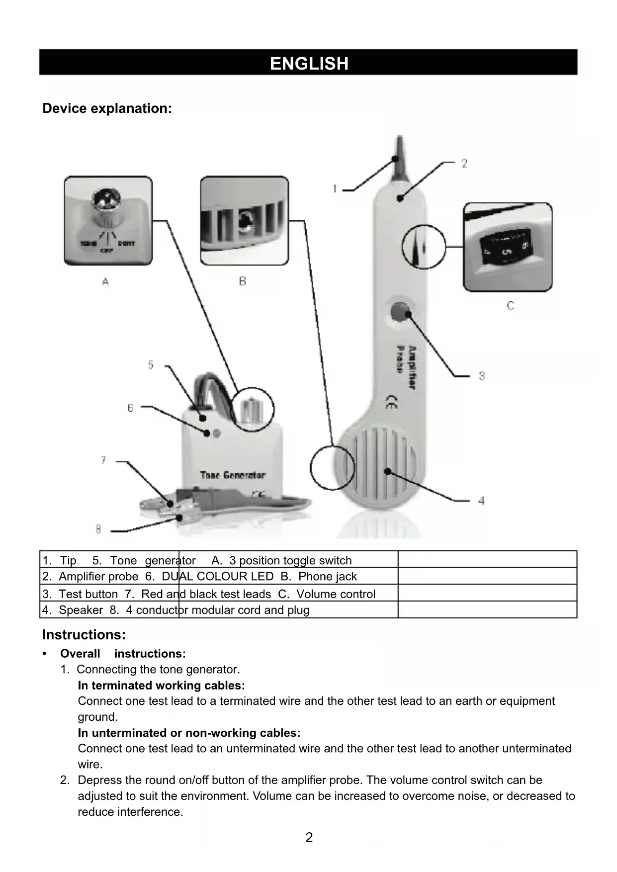
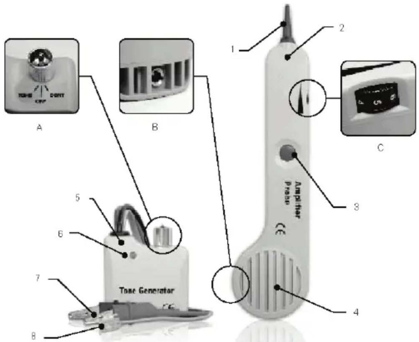
| 1. Tip 5. Tone generator A. 3 position toggle switch | |
| 2. Amplifier probe 6. DUAL COLOUR LED B. Phone jack | |
| 3. Test button 7. Red and black test leads C. Volume control | |
| 4. Speaker 8. 4 conductor modular cord and plug |
Instructions:
Overall instructions:
- Connecting the tone generator.
In terminated working cables:
Connect one test lead to a terminated wire and the other test lead to an earth or equipment ground.
In unterminated or non-working cables:
Connect one test lead to an unterminated wire and the other test lead to another unterminated wire.
-
Depress the round on/off button of the amplifier probe. The volume control switch can be adjusted to suit the environment. Volume can be increased to overcome noise, or decreased to reduce interference.
-
Touch the tip of the amplifier probe to the insulation of each suspect conductor.
- Reception of the tone will be loudest on the subject wire.
- The plug receptacle is provided to be connected to a headset or handset.
- Identifying tip and ring (switch to "Off"):
- Connect the RED test lead to one line and the BLACK lead to the other line.
- The LED will glow GREEN when you connect the RED test lead to the RING SIDE of the line.
- The LED will glow "RED" when you connect the RED test lead to the TIP SIDE of the line.
- Identifying line condition (switch to "OFF"):
- Connect the RED test lead to the RING SIDE of the line and the BLACK lead to the TIP.
- Watch the LED:
a. A bright green LED indicates a clear line
b. No light indicates a busy line
c. A brightly flickering YELLOW light indicates a RINGING line
- Verifying lines (switch to "OFF" then "CONT"):
- Dial the line to be verified.
- While the line is ringing, connect the RED lead to the RING SIDE of the line and the BLACK lead to the TIP.
- In the "Off" position, the indicator light will flicker YELLOW when the test leads are connected to the subject pair.
- If you switch the test set to "CONT", it will terminate the call on the subject line.
- Sending tone (switch to "TONE"):
(Caution: Do not connect to an active AC circuit exceeding 24V in this mode)
- Connect the test leads to the pair, or attach one lead to ground and one lead to either side of the line.
- A dual alternating tone, or a single solid tone, can be selected from the switch inside the tone generator.
- Probe the suspected wires with the amplifier probe. Reception of the tone will be strongest on the subject wire. In the case of ready access to bare conductors, a handset or headset may be used to receive the tone.
- Testing continuity (switch to "CONT"):
(Caution: Do not connect to an active AC or DC circuit in this mode)
- Connect the test leads to the subject pair.
- Use "CONT" position.
- A bright GREEN light indicates continuity. The LED will not glow if the line resistance exceeds 10,000 .
- Testing continuity using tone (switch to "TONE"):
(Caution: Do not connect to an active AC or DC circuit in this mode)
- Connect the test leads to the subject pair.
- Use a handset or headset at the remote end and touch the wire end(s) with the clip lead(s).
- Reception of the tone is an indication of continuity.
- Modular testing:
- All of the above tests are available through the modular plug for line 1 only - red and green wires.
- Coax testing:
- To test unterminated coax, connect the red lead to the outer shield and the black lead to the centre conductor or the red lead to the outer shield and the black lead to the ground.
- To test the terminated coax, connect the red lead to the connector housing and the black lead to the centre pin or the red lead to the connector housing and the black lead to the ground.
- Battery replacement:
- The amplifier probe is maintenance free except for the battery replacement.
Remove the screw from the battery compartment, replace the 9 V battery and screw the lid back on.
Safety precautions:
Do not expose the product to water or moisture.
DO NOT CONNECT TO AN ACTIVE AC CIRCUIT EXCEEDING 24 V IN THIS MODE.
Maintenance:
Clean the product only with a dry cloth.
Do not use cleaning solvents or abrasives.
Warranty:
Any changes and/or modifications to the product will void the warranty. We cannot accept any liability for damage caused by incorrect use of this product.
Disclaimer:
Designs and specifications are subject to change without prior notice. All logos, brands and product names are trademarks or registered trademarks of their respective holders and are hereby recognised as such.
Disposal:

- This product is designated for separate collection at an appropriate collection point. Do not dispose of this product with household waste.
- For more information, contact the retailer or the local authority responsible for waste management.
DEUTSCH
Gerätebeschreibung:
- Koaxialkabel-Test:
(OcToPOxHOb: B 3ToM pExnme He npOn3BODInTe NOkJIIOUeHne K aKTUBHOJ cEHN nepeMeHHoro nII NocToaHHoro ToKa)
- Подклочи Te Измерптеловные Нахонунки К поверяему nape.
-
Испобзун Te пожени «CONT».
3.Ярки 3EJIENbIcBET yka3bIbAeT Ha He nppepbIBHocTb.CBeToIOHOHbI INHdkaTop He 6ydeT MIRatb,ecnCOnpOTNBHeHne WJneΦa npeBbIwaet 10000Ω. -
Поберka He npepbIBHocTn c nOmoIbTOHa (pepeKJIIOueHne B peXIM «TONE»):
(OctopoXHO: B 3TOM pexime He npOn3BODnTe NOdKJIIOueHne K aKTNBHOI ceII nepemehoro nnn noctoHHoro Toka)
- ПодклочиЕ ИЗМерпгельные НаКончнки К поверяемою nape.
- Историяе hayшнки (тарни.typу) на удален hom KoHце Лини и КОСнТecь KoHца (KOHцов) npвoda ckobamн haKOHeuHKnOB (сКбои habOHeuHnka).
-
Ппем TOHa yKa3bIbAeT Ha HenpepbIBHOCTb.
-
IpoBepka ModylbyHoro Ka6eJra:
-
Bce Bblweyka3aHHbIe npOBepKn DoCTynHbI Yepe3 MOnyNbHbI pa3bEm TOnbKO dJa LnHn 1 - KpaChbI n 3eJeHbI Ka6enn.
-
PpOBepKa KoakcnIbHoro Ka6eJra:
-
TTo6bI npOBepnTb He3aedeHbI KOaKcnaHbI Ka6eIb, NOdKJIIOHTe KpaCHbI HaKOHeuHK BHeUHEmy 3KpaHy, a UepHbI - K cEHTpaNbHOMy IpoBOdHky NJI KpaCHbI HaKOHeuHK K BHeUHEmy 3KpaHy, a UepHbI - K 3eMne.
- YTo6bI npOBepNTb 3aDeHnHbI KOaKcnaJbHbI Ka6eJIb, NOdKnIOuHTe KpaCHbI HaKOHeuHK K KopnyCy CoeHNHTeJIa, a UepHbI HAKOHeuHK - K cEHTpaJbHOMy KOHTaKTy IIN KpaCHbI HAKOHeuHK K KopnyCy pa3bema, a UepHbI - K 3emJIe.
3aMeHa 6aTapeH:
- Прбнк усипеля He Tpe6yeT peMOHTa, Крme 3amehbl 6atapei. Bbikpytnte BnHT n3 6atapeHoro OTeKa, 3ameHnte 9B 6atapeko n cHOBa 3akpytnte 6atapeHbI OTcK.
Mepbl 6e3oNaChOCTn:
He donyckaTe BO3eNCTBnB BObl nIbn BnaI.
B 3TOM PEXKIME HE IPOU3BOJNTE NOIKJIIOUEHNE K AKTUBHOJ LENI NEPEMEHHOTOKA. 3HAUYEHNE KOTOPOJ IPREBbIJAET 24B.
TexHnueckoe o6cIyXnBaHne:
OuHuaIe yCTpOInCTBO ToJIbKO cyXoN TkaHbIO.
He npo3BOJTe OYNCy C NcNoJIb3OBAHnEM paCTBOpNTeNe IIN a6pa3NBOB.
TapaHTnA:
IIO6bIe N3MeHnI N / IJN MoDnΦnKaUu yCTpOcTBA npNBeDyT K aHHyJInpOBaHIO npAB NOJB3OBaTeIHa rapaHTnHoe 06CnyXnBaHne. Mbl He Hecem OTBETCTBEHHOCTN 3a yUeP6, NOHeCEHHbICNeDCTBnE HEnpaBnIbHOrO nCNoJIb3OBaHnI 3TOrO pOdyKTA.
Orobopkn:
Iu3aHnTexHNueckne xapaKTePncTnKMOyT 6bItb N3MeHeHbI 6e3 npEBApNTeJbHO rYBeOMJeHn
Bce Iorotnbl6peHIOB nHa3BaHnI npOdyKTOB yBJIOTc TOBaHpBlIM 3HaKaMn NJI
3apeHCTpnpOBaHHbIMN TopROBbIMN MapKAMN INX COOTBETCTByIOUx BnaJeIbUeB IN CNeIOBaTeNbHO pni3HaIOTc TaKOBbIMN.
Yttnn3aun:

Description: Tone generator and probe
COOTBETCTByeT CneIyUOIM CtaHApTaM:
EN61326-1:2006,CISPR112003+A1:2004+A2:2006,IEC61000-4-3:2006+A1:2007, IEC61000-4-8:1993+A1:2000
EU Directive(s) / EG-Richtlinie(n) / Directive(s) EU / EU richtlijn(en) / Direttiva(e) EU / Directive(s) UE / EU direktívak / EU Toimintaohje(ET) / Eu Direktiv(en) / Směrnice EU / Directive(e) UE / Ošnéγíá(ες) TŋCS EE / EU direktiv(er) / EU-direktiv(ene): /Диpečт cuba(bi) EC: 2002/95/EC, 2004/108/EC
's-Hertogenbosch, 21-11-2012
Mr. / Hr. / M. / Dhr. / Sig. / Sr. D. / Ur / Mr. / Herr. / Pan / Di. / K. / Hr. / Herr: / F-H: Randolph Richardson
Chief Operating Officer / Geschäftsführer / Chef des operations / Operationeel Directeur / Responsabile Operativo / Director de Operaciones / Üzemviteli Igazgato / Käyttopäällikkö / Driftschef / Provozní reditel / Director principal / Γενικός Διευθυντής Επιχερήσεων / Chief Operating Officer / Administerende Driftsdirektør / Μυpeκτορ no προύπβοικτυ by Copyright ©
- Instructions:
- Overall instructions:
- - Identifying tip and ring (switch to "Off"):
- - Identifying line condition (switch to "OFF"):
- - Verifying lines (switch to "OFF" then "CONT"):
- - Sending tone (switch to "TONE"):
- (Caution: Do not connect to an active AC circuit exceeding 24V in this mode)
- - Testing continuity (switch to "CONT"):
- (Caution: Do not connect to an active AC or DC circuit in this mode)
- - Testing continuity using tone (switch to "TONE"):
- - Modular testing:
- - Coax testing:
- - Battery replacement:
- Safety precautions:
- Maintenance:
- Warranty:
- Disclaimer:
- Disposal:
- DEUTSCH
- Gerätebeschreibung:
- - Koaxialkabel-Test:
- Mepbl 6e3oNaChOCTn:
- TexHnueckoe o6cIyXnBaHne:
- TapaHTnA:
- Orobopkn:
- Yttnn3aun:
Brand : NEDIS
Model : NWTG100YE
Category : Measuring equipment