
Jupiter Q370 - Desktop computer ASROCK - Free user manual and instructions
Find the device manual for free Jupiter Q370 ASROCK in PDF.

User questions about Jupiter Q370 ASROCK
0 question about this device. Answer the ones you know or ask your own.
Ask a new question about this device
Download the instructions for your Desktop computer in PDF format for free! Find your manual Jupiter Q370 - ASROCK and take your electronic device back in hand. On this page are published all the documents necessary for the use of your device. Jupiter Q370 by ASROCK.
USER MANUAL Jupiter Q370 ASROCK
Published August 2018

This device complies with Part 15 of the FCC Rules. Operation is subject to the following two conditions:
(1) this device may not cause harmful interference, and
(2) this device must accept any interference received, including interference that may cause undesired operation.
CALIFORNIA, USA ONLY
The Lithium battery adopted on this motherboard contains Perchlorate, a toxic substance controlled in Perchlorate Best Management Practices (BMP) regulations passed by the California Legislature. When you discard the Lithium battery in California, USA, please follow the related regulations in advance.
"Perchlorate Material-special handling may apply, see www.dtsc.ca.gov/hazardouswaste/perchlorate"
AUSTRALIA ONLY
Our goods come with guarantees that cannot be excluded under the Australian Consumer Law. You are entitled to a replacement or refund for a major failure and compensation for any other reasonably foreseeable loss or damage caused by our goods. You are also entitled to have the goods repaired or replaced if the goods fail to be of acceptable quality and the failure does not amount to a major failure.
The terms HDMI ^™ and HDMI High-Definition Multimedia Interface, and the HDMI logo are trademarks or registered trademarks of HDMI Licensing LLC in the United States and other countries.

HIGH-DEFINITION MULTIMEDIA INTERFACE
Motherboard Layout
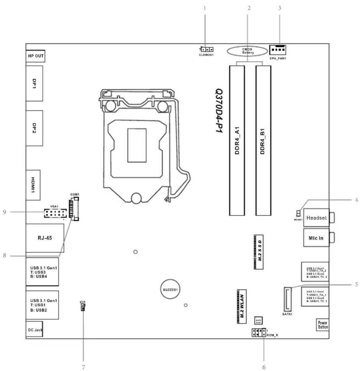
No. Description
1 Clear CMOS Jumper (CLRMOS1)
2 2 x 260-pin DDR4 SO-DIMM Slots (DDR4_A1, DDR4_B1)
3 CPU Fan Connector (CPU_FAN1)
4 2.5W Mono Out Speaker Header (MONO1)
5 SATA3 Connector (SATA0)
6 ROM Recovery Header (ROM_R)
7 Chassis Intrusion Header (CI1)
8 COM Port Header (COM1)
9 D-Sub Header (VGA1)
Front Panel
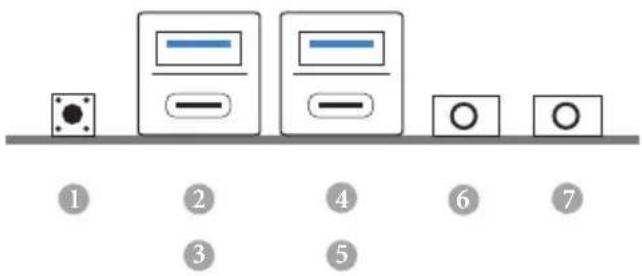
No. Description No. Description
1 Power Button (SW1) 5 USB 3.1 Gen2 Type-C Port
2 USB 3.1 Gen1 Type-A Port (USB31_TA_1) (USB31_TC_2)
3 USB 3.1 Gen2 Type-C Port (USB31_TC_1) 6 Microphone Input (AUDIO2)
4 USB 3.1 Gen1 Type-A Port (USB31_TA_2) 7 Headphone/Headset Jack
Rear Panel
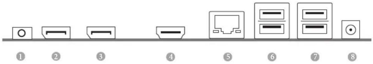
No. Description No. Description
1 Headphone Jack 5 LAN RJ-45 Port*
2 DisplayPorts 1.2 (DP1) 6 USB 3.1 Gen1 Ports (USB3_34)
3 DisplayPorts 1.2 (DP2) 7 USB 3.1 Gen1 Ports (USB3_12)
4 HDMI Port 8 DC Jack
* There are two LEDs on each LAN port. Please refer to the table below for the LAN port LED indications.
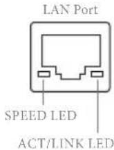
Activity / Link LED Speed LED
Status Description Status Description
| Off No Link Off | 10Mbps connection | ||
| Blinking | Data Activity | Green | 100Mbps connection |
| On | Link | Orange | 1Gbps connection |
Chapter 1 Introduction
Thank you for purchasing Q370D4-P1 motherboard. In this documentation, Chapter 1 and 2 contains the introduction of the motherboard and step-by-step installation guides. Chapter 3 contains the operation guide of the software and utilities. Chapter 4 contains the configuration guide of the BIOS setup.

Because the motherboard specifications and the BIOS software might be updated, the content of this documentation will be subject to change without notice.
1.1 Package Contents
• Q370D4-P1 Motherboard
• Q370D4-P1 Quick Installation Guide
• Q370D4-P1 Support CD
• 1 x Serial ATA(SATA) Data with Power Cable (Optional)
• 1 x Screw for M.2 Socket (M2*2) (Optional)
• 1 x Screw for WiFi Module (M2*2) (Optional)
1.2 Specifications
| Platform | 6.7-in x 6.8-in, 17.0 cm x 17.2 cm |
| CPU | Supports 8^th Generation Intel® CoreTM Processors (Socket 1151)Supports CPU up to 65W5 Power Phase designSupports Intel® Turbo Boost 2.0 Technology |
| Chipset | Intel® Q370Supports Intel® vProTM TechnologySupports Intel® Active Management Technology 12.0* Intel® vProTM Technology and Intel® Active Management Technology 12.0 can be supported only with Intel® CoreTM vProTM processor family |
| Memory | Dual Channel DDR4 Memory Technology2 x DDR4 SO-DIMM SlotsSupports DDR4 2666/2400/2133 non-ECC, un-buffered memoryMax. capacity of system memory: 32GBSupports Intel® Extreme Memory Profile (XMP) 2.0 |
| Expansion Slot | 1 x M.2 Socket (Key E), supports type 2230 WiFi/BT module |
| Graphics | Intel® UHD Graphics Built-in Visuals and the VGA outputs can be supported only with processors which are GPU integrated.Supports Intel® UHD Graphics Built-in Visuals : Intel® Quick Sync Video with AVC, MVC (S3D) and MPEG-2 Full HW Encode1, Intel® InTruTM 3D, Intel® Clear Video HD Technology, Intel® InsiderTM, Intel® UHD GraphicsDirectX 12HWAEncode/Decode: AVC/H.264, HEVC/H.265 8-bit, HEVC/H.265 10-bit, VP8, VP9 8-bit, VP9 10-bit (Decode only), MPEG2, MJPEG, VC-1 (Decode only) |
• Max. shared memory 1024MB
* The size of maximum shared memory may vary from different operating systems.
- Four graphics output options: DisplayPort 1.2, DisplayPort 1.2, HDMI and D-Sub
* Supports up to 3 displays simultaneously
- Supports HDMI with max. resolution up to 4K x 2K (4096x2160) @ 30Hz
- Supports D-Sub with max. resolution up to 1920x1200 @ 60Hz
- Supports DisplayPort 1.2 with max. resolution up to 4K x 2K (4096x2304) @ 60Hz
- Supports Auto Lip Sync, Deep Color (12bpc), xvYCC and HBR (High Bit Rate Audio) with HDMI Port (Compliant HDMI monitor is required)
• Supports HDCP with HDMI and DisplayPort 1.2 Ports
- Supports 4K Ultra HD (UHD) playback with HDMI and DisplayPort 1.2 Ports
Audio
• Realtek ALC233-VB2 Audio Codec
• 1 x Headphone/Headset Jack
- 1 x MIC-In
LAN
• Gigabit LAN 10/100/1000 Mb/s
• Giga PHY Intel® I219LM
• Supports Wake-On-LAN
• Supports Lightning/ESD Protection
• Supports Energy Efficient Ethernet 802.3az
- Supports PXE
Front
- 1 x Power Button
Panel I/O
• 1 x Headphone/Headset Jack
• 2 x USB 3.1 Gen1 Type-A Ports (Supports ESD Protection)
• 2 x USB 3.1 Gen2 Type-C Ports (Supports ESD Protection)
• 1 x Microphone Input Jack
Rear Panel I/O
- 1 x DC Jack (Compatible with the 19V power adapter)* * Please use 90W power adapter for 65W CPU and 65W power adapter for 35W CPU.
• 1 x Headphone Jack
- 1 x HDMI Port
- 2 x DisplayPort 1.2
• 4 x USB 3.1 Gen1 Ports (Support ESD Protection)
- 1 x RJ-45 LAN Port with LED (ACT/LINK LED and SPEED LED)
Storage
- 1 x SATA3 6.0 Gb/s with Power Connector, support NCQ, AHCI and Hot Plug
- 1 x Ultra M.2 Socket, support type 2280 M.2 SATA3 6.0 Gb/s module and M.2 PCI Express module up to Gen3 x4 (32 Gb/s)*
* Supports Intel® Optane ™ Technology
* Supports NVMe SSD as boot disks
Connector
- 1 x D-Sub Header
• 1 x COM Port Header
• 1 x Chassis Intrusion Header
• 1 x CPU Fan Connector (4-pin)
• 1 x Internal Speaker Header
• 1 x Mono-Out Header
• 1 x ROM Recovery Header
BIOS
• AMI UEFI Legal BIOS with multilingual GUI support
• ACPI 6.0 Compliant wake up events
- SMBIOS 2.7 Support
Hardware
• CPU Temperature Sensing
• CPU Fan Tachometer
- CPU Quiet Fan (Auto adjust chassis fan speed by CPU temperature)
• CPU Fan Multi-Speed Control
- CASE OPEN detection
• Voltage monitoring: +12V, +5V, +3.3V, CPU Vcore
os
- Microsoft® Windows® 10 64-bit
Certifica-
- FCC, CE
tions
- ErP/EuP ready (ErP/EuP ready power supply is required)

Please realize that there is a certain risk involved with overclocking, including adjusting the setting in the BIOS, applying Untied Overclocking Technology, or using third-party overclocking tools. Overclocking may affect your system's stability, or even cause damage to the components and devices of your system. It should be done at your own risk and expense. We are not responsible for possible damage caused by overclocking.
Chapter 2 Installation
This is a Proprietary form factor motherboard. Before you install the motherboard, study the configuration of your chassis to ensure that the motherboard fits into it.
Pre-installation Precautions
Take note of the following precautions before you install motherboard components or change any motherboard settings.
- Make sure to unplug the power cord before installing or removing the motherboard components. Failure to do so may cause physical injuries and damages to motherboard components.
- In order to avoid damage from static electricity to the motherboard's components, NEVER place your motherboard directly on a carpet. Also remember to use a grounded wrist strap or touch a safety grounded object before you handle the components.
- Hold components by the edges and do not touch the ICs.
- Whenever you uninstall any components, place them on a grounded anti-static pad or in the bag that comes with the components.
- When placing screws to secure the motherboard to the chassis, please do not over-tighten the screws! Doing so may damage the motherboard.
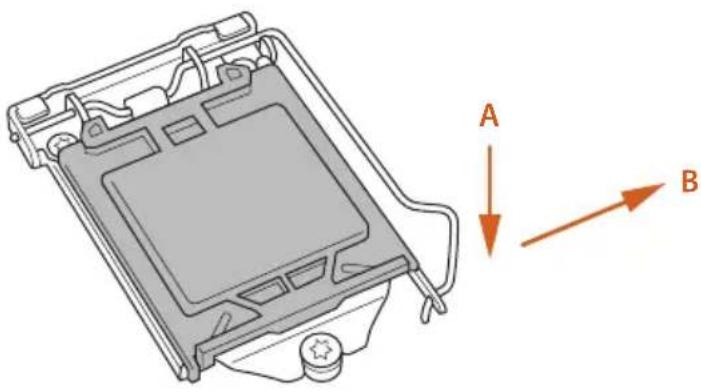
2.1 Installing the CPU

- Before you insert the 1151-Pin CPU into the socket, please check if the PnP cap is on the socket, if the CPU surface is unclean, or if there are any bent pins in the socket. Do not force to insert the CPU into the socket if above situation is found. Otherwise, the CPU will be seriously damaged.
- Unplug all power cables before installing the CPU.
1
natural_image
Technical line drawing of a device casing with labeled directional arrows (A and B), no readable text or symbols present.2
natural_image
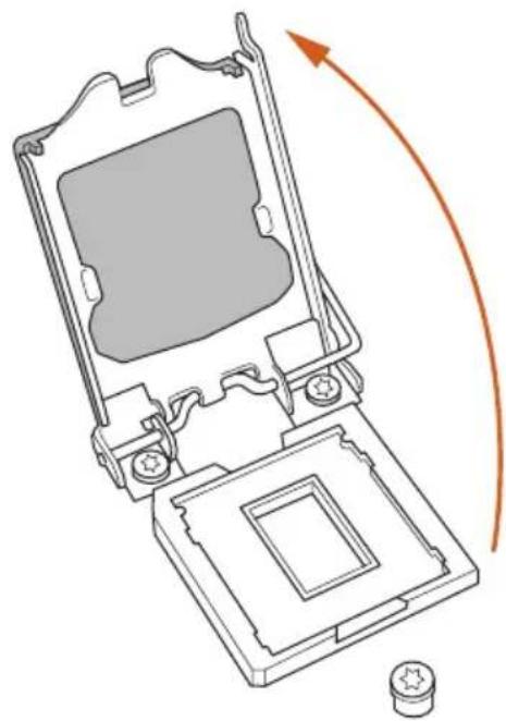
Technical line drawing of a mechanical device with an arrow indicating rotation or movement (no text or symbols present)3
natural_image
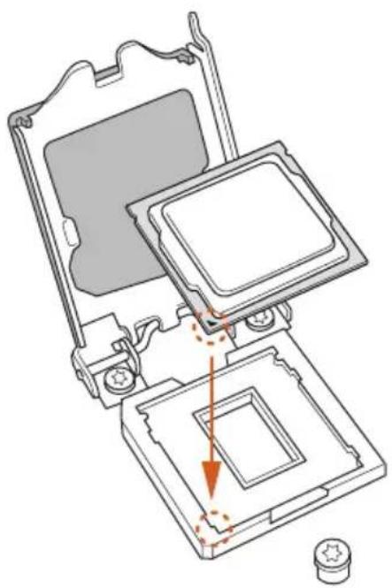
Technical diagram of a computer processor internal structure showing mounting holes and internal components (no text or labels)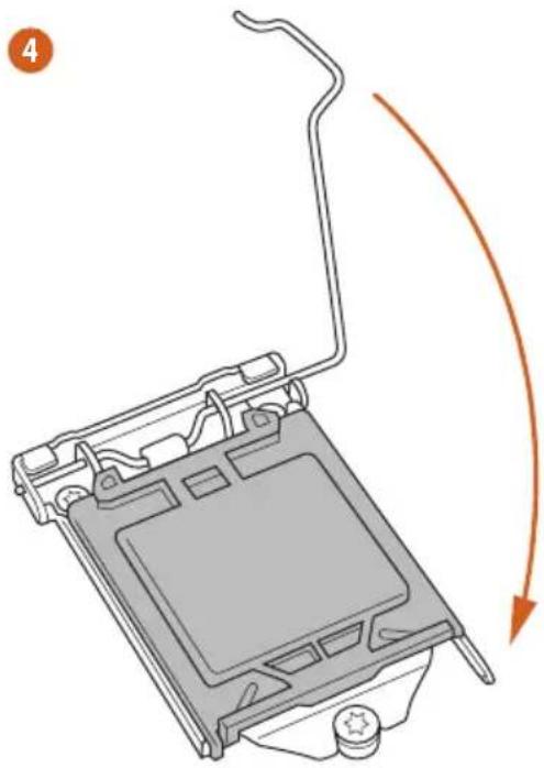
natural_image
Diagram of a computer monitor with an orange curved arrow indicating motion or rotation (no text or symbols present)5

natural_image
Diagram of a computer processor showing internal components and a close-up view of the base (no text or symbols)
Please save and replace the cover if the processor is removed. The cover must be placed if you wish to return the motherboard for after service.
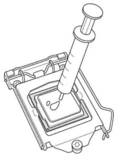
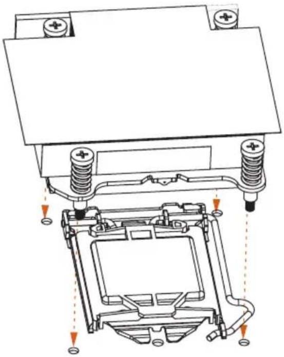
2.2 Installing the CPU Fan and Heatsink
natural_image
Line drawing of a pipette dispensing liquid into a square container (no text or symbols)1
natural_image
Technical diagram of a mechanical assembly with springs and housing (no text or labels)2
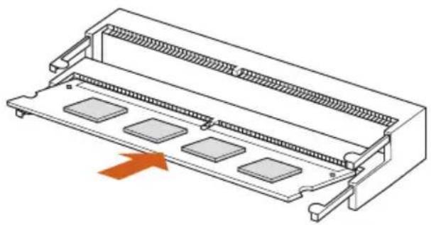
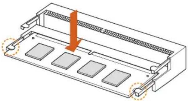
2.3 Installing Memory Modules (SO-DIMM)
This motherboard provides two 260-pin DDR4 (Double Data Rate 4) SO-DIMM slots.

It is not allowed to install a DDR, DDR2 or DDR3 memory module into a DDR4 slot; otherwise, this motherboard and SO-DIMM may be damaged.

The SO-DIMM only fits in one correct orientation. It will cause permanent damage to the motherboard and the SO-DIMM if you force the SO-DIMM into the slot at incorrect orientation.
- Carefully insert the SO-DIMM memory modules into the slot at a 30-degree angle.
natural_image
Technical line drawing of a mechanical component with multiple slots and a highlighted arrow (no text or symbols)- Push down until the modules snap into place.
natural_image
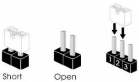
Technical diagram of a mechanical component with a highlighted section and orange arrow indicating force or direction (no text or symbols present)2.4 Jumpers Setup
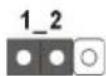
The illustration shows how jumpers are setup. When the jumper cap is placed on the pins, the jumper is "Short". If no jumper cap is placed on the pins, the jumper is "Open". The illustration shows a 3-pin jumper whose pin1 and pin2 are "Short" when a jumper cap is placed on these 2 pins.
Clear CMOS Jumper (CLRMOS1)
(see p.1, No. 1)
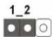
Default
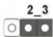
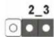
Clear CMOS
CLRMOS1 allows you to clear the data in CMOS. To clear and reset the system parameters to default setup, please turn off the computer and unplug the power cord from the power supply. After waiting for 15 seconds, use a jumper cap to short pin2 and pin3 on CLRMOS1 for 5 seconds. However, please do not clear the CMOS right after you update the BIOS. If you need to clear the CMOS when you just finish updating the BIOS, you must boot up the system first, and then shut it down before you do the clear-CMOS action. Please be noted that the password, date, time, and user default profile will be cleared only if the CMOS battery is removed.

- The Clear CMOS Button has the same function as the Clear CMOS jumper.
- If you clear the CMOS, the case open may be detected. Please adjust the BIOS option "Clear Status" to clear the record of previous chassis intrusion status.
2.5 Onboard Headers and Connectors

Onboard headers and connectors are NOT jumpers. Do NOT place jumper caps over these headers and connectors. Placing jumper caps over the headers and connectors will cause permanent damage to the motherboard.
Serial ATA3 Connector (SATA0: see p.1, No. 5)

This SATA3 connector supports SATA data cables for internal storage devices with up to 6.0 Gb/s data transfer rate.
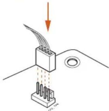
CPU Fan Connectors (4-pin CPU_FAN1) (see p.1, No. 3)
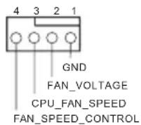
This motherboard provides a 4-Pin CPU fan (Quiet Fan) connector. If you plan to connect a 3-Pin CPU fan, please connect it to Pin 1-3.
Serial Port Header (9-pin COM1) (see p.1, No. 8)
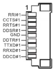
This COM1 header supports a serial port module.
Chassis Intrusion Header (2-pin CI1) (see p.1, No. 7)
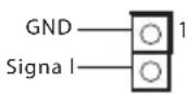
This motherboard supports CASE OPEN detection feature that detects if the chassis cove has been removed. This feature requires a chassis with chassis intrusion detection design.
2.5W Audio Amp Output Header
(2-pin MONO1)
(see p.1, No. 4)
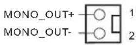
Please connect the chassis speaker to this header.
ROM Recovery Header
(7-pin ROM_R)
(see p.1, No. 6)
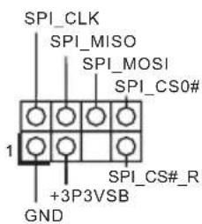
This ROM Recovery Connector allows qualified technicians to reload firmware into the SPI boot flash in case there is problem with the data.
D-Sub Header (10-pin VGA1)
(see p.1, No. 9)
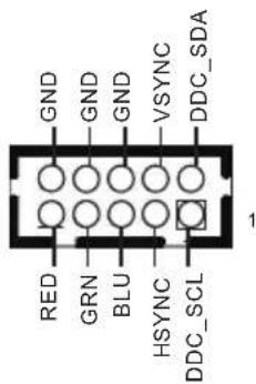
This header is to connect a D-Sub monitor via an adapter cable
2.6 Smart Switch
The motherboard has one smart switch: Power Button.
Power Button
(SW1)
(see p.3, No. 1)
Power Button allows users to quickly turn on/off the system.
2.7 M.2 WiFi/BT Module Installation Guide
The M.2, also known as the Next Generation Form Factor (NGFF), is a small size and versatile card edge connector that aims to replace mPCIe and mSATA. The M.2 Socket (Key E) supports type 2230 WiFi/BT module.
* The M.2 socket does not support SATA M.2 SSDs.
Installing the WiFi/BT module
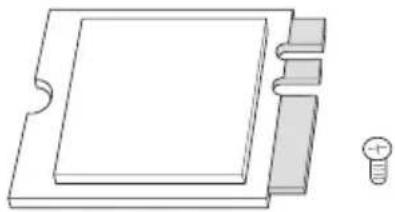
natural_image
Pure technical line drawing of a mechanical component with no text or symbolsStep 1
Prepare a type 2230 WiFi/BT module and the screw.
natural_image
Pure electrical circuit lines without any symbols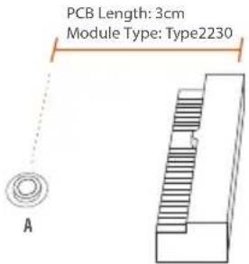
Step 2
Find the nut location to be used.
natural_image
Pure mechanical assembly diagram without any text, numbers, or symbolsStep 3
Gently insert the WiFi/BT module into the M.2 slot. Please be aware that the module only fits in one orientation.
natural_image
Diagram of a mechanical assembly with a screw and nut, showing motion direction (no text or symbols)Step 4
Tighten the screw with a screwdriver to secure the module into place. Please do not overtighten the screw as this might damage the module.
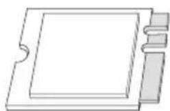
2.8 M.2\_SSD (NGFF) Module Installation Guide (M2\_1)
The Ultra M.2, also known as the Next Generation Form Factor (NGFF), is a small size and versatile card edge connector that aims to replace mPCIe and mSATA. The Ultra M.2 Socket (M2_1) supports SATA3 6.0 Gb/s module and M.2 PCI Express module up to Gen3 x4 (32 Gb/s).
Installing the M.2\_SSD (NGFF) Module
natural_image
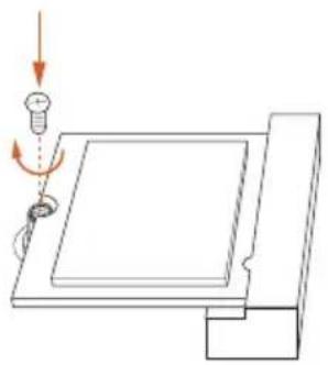
Pure technical line drawing of a rectangular component with internal features and a small protrusion (no text or symbols)Step 1
Prepare a M.2_SSD (NGFF) module and the screw.
natural_image
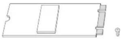
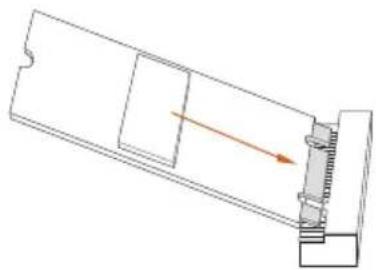
Pure mechanical diagram showing a lever mechanism with no text or symbolsStep 2
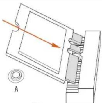
Gently insert the M.2 (NGFF) SSD module into the M.2 slot. Please be aware that the M.2 (NGFF) SSD module only fits in one orientation.
natural_image
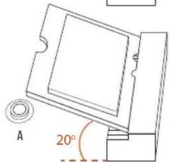
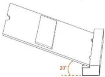
Technical line drawing of a mechanical component with a 20-degree angle标注 (no text or symbols beyond the angle marker)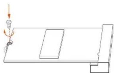
natural_image
Simple line drawing of a mechanical setup with a lever and base plate (no text or symbols)Step3
Tighten the screw with a screwdriver to secure the module into place. Please do not overtighten the screw as this might damage the module.
M.2\_SSD (NGFF) Module Support List
Vendor Interface P/N
| ADATA PCIe ADATA ASX7000NPC-512GT-C (XPG SX7000) (NVMe) | ||
| ADATA PCIe ADATA ASX8000NPC-512GM-C (XPG ASX8000) (NVMe) | ||
| Apacer PCIe Apacer Z280 AP240GZ280-240G (NVMe) | ||
| Intel PCIe Intel Optane Memory 32GB (MEMPEK1W032GA)(NVMe) | ||
| Intel PCIe Intel Optane Memory 16GB (MEMPEK1W016GA)(NVMe) | ||
| INTEL PCIe INTEL 600P-SSDPEKKW256G7-256GB (NVMe) | ||
| INTEL PCIe INTEL 600P-SSDPEKKW128G7-128GB (NVMe) | ||
| INTEL PCIe INTEL 6000P-SSDPEKKF256G7-256GB (NVMe) | ||
| INTEL PCIe INTEL 6000P-SSDPEKKF512G7-512GB (NVMe) | ||
| Kingston PCIe Kingston SHPM2280P2/240G | ||
| PATRIOT PCIe PATRIOT Hellfire M2 (240G) (NVMe) | ||
| PLEXTOR PCIe PLEXTOR PX-256M8PeG (NVMe) | ||
| PLEXTOR PCIe PLEXTOR PX-256M8SeGN (NVMe) | ||
| Samsung | PCIe | Samsung XP941-512G (MZHPU512HCGL) |
| Samsung | PCIe | Samsung 950Pro-512G (NVMe) |
| Samsung | PCIe Samsung 950Pro-256G (NVMe) | |
| Samsung | PCIe Samsung MZ-VLW1280 (PM961) (NVMe) | |
| Samsung | PCIe Samsung MZ-VPW1280 (SM961) (NVMe) | |
| TOSHIBA | PCIe | TOSHIBA XG3-128G (NVMe) |
| TOSHIBA | PCIe | TOSHIBA OCZ RD400-256G (NVMe) |
| WD | PCIe | WD WDS512G1X0C-00ENX0 (NVMe) |
| WD | PCIe | WD WDS256G1X0C-00ENX0 (NVMe) |
| ADATA | SATA | ADATA - SU800-SU800NS38-256GT-C-256G |
| ADATA | SATA | ADATA - SU800-SU800NS38-512GT-C-512G |
| Crucial | SATA | Crucial-CT240M500SSD4-240GB |
| Ezlink | SATA | Ezlink P51B-80-120GB |
| INTEL | SATA | INTEL-535-SSDSCKJF240A5-QS63-MLC-240G |
| INTEL | SATA | INTEL 540S-SSDSCKKW240H6-240GB |
| Kingston | SATA | Kingston-RBU-SNS8400S3/180GD |
| LITON | SATA | LITON LJH-256V2G-11-256GB |
| PLEXTOR | SATA | PLEXTOR - M7V-PX-128M7VG-128GB |
| PLEXTOR | SATA | PLEXTOR PX-128M6G-128GB |
| Sandisk | SATA | Sandisk X400-SD8SN8U-128G |
| Sandisk | SATA | Sandisk Z400s-SD8SNAT-128G |
| Transcend | SATA | Transcend TS256GMTS800-256GB |
| V-Color | SATA | V-Color 120G |
| V-Color | SATA | V-Color 240G |
| WD | SATA | WD BLUE WDS100T1B0B |
| WD | SATA | WD Green WDS240G1G0B-00RC30 |
For the latest updates of M.2_SSD (NFGG) module support list, please visit our website for details.
1 Einleitung
Cavalier Clear CMOS (CLRMOS1)
(voir p.1, No. 1)
1_2

Par défaut
• Supporto WOL (Wake-On-LAN)
• Supporto Energy Efficient Ethernet 802.3az
- Supporto PXE
Pannello I/O frontale
E/S do painel frontal
Apagar o Jumper CMOS (CLRMOS1)
(ver p.1, N.° 1)
Padrão
Apagar CMOS
If you need to contact ASRock or want to know more about ASRock, you're welcome to visit ASRock's website at http://www.asrock.com; or you may contact your dealer for further information. For technical questions, please submit a support request form at https://event.asrock.com/tsd.asp
ASRock Incorporation
2F., No.37, Sec. 2, Jhongyang S. Rd., Beitou District,
Taipei City 112, Taiwan (R.O.C.)
ASRock EUROPE B.V.
Bijsterhuizen 11-11
6546 AR Nijmegen
The Netherlands
Phone: +31-24-345-44-33
Fax: +31-24-345-44-38
ASRock America, Inc.
13848 Magnolia Ave, Chino, CA91710
U.S.A.
Phone: +1-909-590-8308
Fax: +1-909-590-1026
DECLARATION OF CONFORMITY
Per FCC Part 2 Section 2.1077(a)

Product Name : Motherboard
Model Number: Q370D4-P1
Conforms to the following specifications:
☒ FCC Part 15, Subpart B, Unintentional Radiators
Supplementary Information:
This device complies with part 15 of the FCC Rules. Operation is subject to the following two conditions: (1) This device may not cause harmful interference, and (2) this device must accept any interference received, including interference that may cause undesired operation.
EU Declaration of Conformity
For the following equipment:
Motherboard
(Product Name)
Q370D4-P1
(Model Designation / Trade Name)
EMC — Directive 2014/30/EU (from April 20th, 2016)
□ EN 55022:2010/AC:2011 Class B
EN 55024:2010/A1:2015
EN 55032:2012+AC:2013 Class B
EN 61000-3-3:2013
EN 61000-3-2:2014
□ LVD — Directive 2014/35/EU (from April 20th, 2016)
□ EN 60950-1:2011+A2:2013 □
EN 60950-1:2006/A12:2011
☒ RoHS — Directive 2011/65/EU
CE marking

(EU conformity marking)