KAP 305JL - Saw Holzmann - Free user manual and instructions
Find the device manual for free KAP 305JL Holzmann in PDF.

| Product type | Professional miter saw |
| Brand | Holzmann |
| Model | KAP 305JL |
| Max. blade diameter | 305 mm |
| Blade arbor | 25.4 mm |
| Max. blade thickness | 3 mm |
| Max. rotational speed | ≥ 4200 min⁻¹ |
| Power supply | 230 V ~ 50 Hz |
| Cutting functions | Miter cuts, sliding cuts, groove cutting |
| Safety devices | Protective cover, transport lock, double safety start, class 2 laser |
| Cutting guide | Left/right back guide, double bar guide, hold-down clamp |
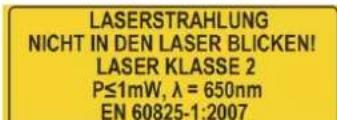
| Laser | Class 2 laser, P ≤ 1 mW, λ = 650 nm |
| Compatible materials | Wood and plastics |
| Routine maintenance | Cleaning after each use, emptying the dust bag, checking screws and blade |
| Blade replacement | Loosen clamping screw, remove flange, change blade respecting tooth direction |
| Carbon brush replacement | When wear < 4 mm, replace both brushes |
| Warranty | 12 months (non-commercial use), 6 months (commercial use) |
| After-sales service | Contact the dealer or HOLZMANN Maschinen GmbH |
Frequently Asked Questions - KAP 305JL Holzmann
User questions about KAP 305JL Holzmann
0 question about this device. Answer the ones you know or ask your own.
Ask a new question about this device
Download the instructions for your Saw in PDF format for free! Find your manual KAP 305JL - Holzmann and take your electronic device back in hand. On this page are published all the documents necessary for the use of your device. KAP 305JL by Holzmann.
USER MANUAL KAP 305JL Holzmann
MANN® Z70H MASCHINEN
natural_image
Product photo of a metal cutting machine with a red and silver base, labeled 'HOLZMANN MASCHINEN' (no additional text or symbols visible)KAP 305JL
CE

EN: Read the operation manual carefully before first use.
12.1 Intended Use .... 35
12.2 Security instructions....36
12.3 Remaining risk factors....39
13 ASSEMBLY 40
13.1 Delivery content ....40
13.2 Assembly 40
13.3 Transport....40
13.4 Workplace requirements....40
14 OPERATION 41
14.1 Operation instructions....41
14.2 Modes 42
14.2.1 Angle settings 42
14.3 Operation....43
14.3.1 Switch on & prepare to cut....43
14.3.2 Switch off 43
14.4 Operation modes ....43
14.4.1 Miter cuts 43
14.4.2 Sliding cuts 43
14.4.3 Slot cuts....43
14.5 OPERATION NOTICES 43
15 MAINTENANCE 44
15.1 Maintenance plan....44
15.2 Change saw blade....45
15.3 Change the carbon brush....47
15.4 Storaging....47
15.5 Cleaning....47
15.6 Disposal....47
16 TROUBLE SHOOTING 48
17 ESTIMADO CLIENTE (ES) 49
18 SEGURIDAD 50
EN ATTENTION! Ignoring the safety signs and warnings applied on the machine as well as ignoring the security and operating instructions can cause serious injuries and even lead to death.
EN READ THE MANUAL! Read the user and maintenance manual carefully and get familiar with the controls in order to use the machine correctly and to avoid injuries and machine defects.
EN EC-CONFORM: This product complies with EC-directives
natural_image
Four blue circular icons representing different workplace safety symbols: hand, glove, helmet, and gear (no text or labels)EN Protective clothing!
EN Stop and pull out the power plug before any break and engine maintenance!
EN Only trained staff!
EN Operation with jewelry forbidden!
EN Operation with tie forbidden!
EN Operation with long hair forbidden!
EN Warning about cut injuries!
EN Protect from moisture!
ES Proteja de la humedad!
EN Protection class II!
natural_image
Three labeled images: a black garment with red 'H', a gray L-shaped metal object, and a packaged bag with red 'J' (no text or symbols on objects)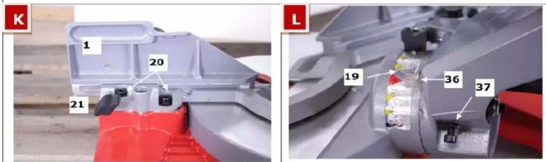
text_image
K 1 20 21 L 19 36 37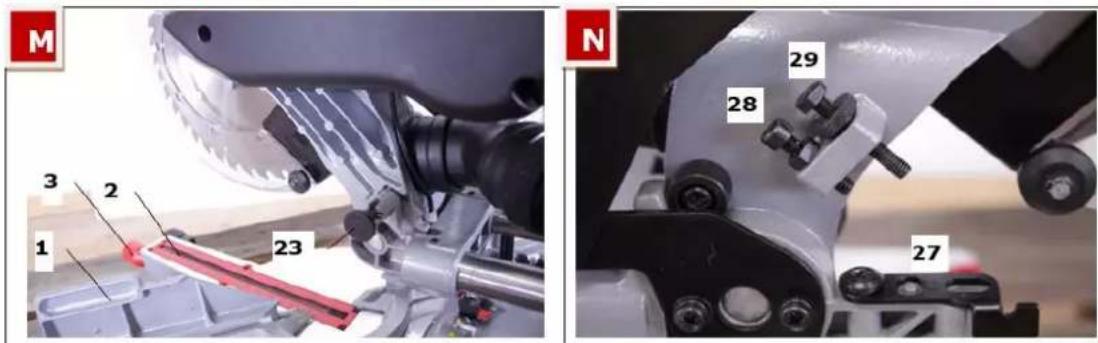
text_image
M 3 2 1 23 N 29 28 274 TECHNIK / TECHNIC
4.1 Komponenten / components / componentes / composants / component / komponentov / komponenty
| 1 | Werkstückanschlag / Back fence / Guía tope / Guide butée / Doraz obrobku / Doraz obrobku / Ogranicznik | 20 | Einstellschrauben zu Werkstückanschlag / Back fence adjustment screws / Tornillo de ajuste de la guía tope / Vis de réglage de guide butée / Ustavovacia skrutka dorazu obrobka / Ustavovací šroub dorazu obrobku / Šruby ustalające do ogranicznika |
| 2 | Schlitz / Slit / Ranura / Rainure / Drážka / Drážka / Szczelina | 21 | Feststellhebel Werkstückanschlag / Back fence fixing knob / Palanca de bloqueo de la guía tope / Levier de blocage de guide butée / Páčka zaistenia dorazu obrobka / Páčka zajištění dorazu obrobku / Dźwignia ustalająca ogranicznika |
| 3 | Feststellknauf / Fixing knob / Pomo de bloqueo / Bouton de verrouillage / Zaistovacia hlavica / Zajišťovací hlavice / Gałka ustalająca | 22 | Feststellschraube Zugstangen / Sliding device fixing knob / Tornillo de bloque del brazo / Vis de blocage du bras / Zaistovacia skrutka tiahla / Zajišťovací šroub táhla / Šruba ustalająca cięgła |
| 4 | Einrasthebel / Angle fixing lever / Palanca de fijación / Levier de serrage / Západka / Západka / Dźwignia blokująca | 23 | Arretierung Sägeaggregat / Interlock knob / Bloqueo del grupo de sierra / Verrouillage d’unité de scie / Aretácia agregátu pily / Aretace agregátu pily / Aretacja agregatu tnącego |
| 5 | Winkelskala / Angle measuring scale / Escala de ángulo / Échelle d’angle / Uhlová stupnica / Stupnice úhloměru / Skala wskazująca kąt | 24 | Ein/Aus-Schalter / ON-OFF-switch / Interruptor encendido-apagado / Interrupteur allumage- arrêt / Hlavný vypínač EIN-AUS / Hlavní vypínač ON-OFF / Włącznik-wyłącznik |
| 6 | Laser / Laser / Láser / Laser / Laser / Laser/ Laser | 25 | Sicherheitshebel für Sägeblattschutz / Security lock lever / Palanca de seguridad del protector del disco / Levier de sécurité de protection de lame / Bezpečnostná páčka ochrany pílového kotúča / Bezpečnostní páčka ochrany pilového kotouče / Dźwignia bezpieczeństwa osłony brzes-zczotu |
| 7 | Werkstückausleger / Workpiece boom / Barra estabilizadora / Barre stabilisatrice / | 26 | Riemenabdeckung / Belt cover / Cubierta de la correa / Couvercle de courroie / Kryt remeña / Kryt řemene / Osłona pasów |
| 8 | Ausgleichswinkel / Compensation angle / Tope / Butée / | 27 | Tiefenanschlag / Depth stop / Tope de profundidad / Butée de profondeur / Híbkový doraz / Hloubkový doraz / Ogranicznik głębokości cięcia |
| 10 | Werkstück-Niederhalter / Downholder / Prensor / Presseur / Prítlačný držiak obrobku / Prítlačný držák obrobku / Element unieruchamiający obrabiany materiał | 28 | Einstellschraube Tiefenanschlag / Depth stop adjustment screw / Tornillo de ajuste de tope de profundidad / Vis de réglage de la butée de profondeur / Ustavovacia skrutka híbkového dorazu / Ustavovací šroub hloubkového dorazu / Šruba ustalająca głębokość cięcia |
| 11 | Zugstangen / Sliding bars / Barras deslizantes / Barres coulissantes / Tiahla / Táhla / Cięgła | 29 | Tiefeneinstellschraube für Nutschnitte / Adjustment screw for slot cut depth / Tornillo de ajuste de profundidad de corte en ranura / Vis de réglage de la profondeur de coupe en fente / Ustavovacia skrutka hlíbky rezu drážky / Ustavovací šroub hloubky řezu drážky / Šruba ustalająca głebokość wpustów |
| 12 | Abdeckung Schleifkohle / Cover carbon brush / Cubierta de la escobilla / Couvercle de balai de charbon / Krytka uhlíkovej kefy / Krytka uhlíkového kartáče / Osłona szlifierki węglowej | 31 | Kreissägeblatt / Saw blade / Disco de sierra / Lame de scie / Kotúč píly / Kotouč pily / Tarcza tnąca |
| 13 | Transportgriff / Transport handle / Asa de transporte / Poignée de transport / Transportné madlo / Transportní madlo / Uchwyt do transportu | 33 | Spänefangsack / Dust bag / Bolsa de aspiración / Sac d'aspirateur / Vak na piliny / Vak na piliny / Worek na wióry |
| 14 | Bediengriff / Handle / Mango de operación / Poignée de commande / Rukovat obsluhy / Rukoječ obsluhy / Uchwyt do obsługi | 34 | Innensechskantschlüssel / Pipe wrench / Llave de tubo / Clé / Imbusový klúč / Imbusový klíč / Klucz imbusowy |
| 15 | Kreissägeblattschutzabdeckung /Saw blade protection / Cubierta de protección del disco / Couvercle de protection de la lame / Ochranný kryt pílového kotúča / Ochranný kryt pilového kotouče / Osłona tarczy tnącej | 35 | Ersatzschleifkohle / carbon brush replacement / Repuesto de escobillas / Balais de rechange / Náhradná uhlíková kefa / Náhradní uhlíkový kartáč / Zapasowe szczotki węglowe |
| 16 | Typenschild / type plate / Placa de identificación / Plaque d'identification / Typový štítok / Typový štítek / Tabliczka znamionowa | 36 | Gradanzeige Schwenkung / Tilt angle indicator / Indicador de ángulo de inclinación / Indicateur d'angle / Stupnica natočenia / Stupnice natočení / Wskaźnik stopnia wychylenia |
| 17 | Anschlusskabel / Cable / Cable de conexión / Câble de connexion / Sieťový kábel / Síťový kabel / Kabel przyłączeniowy | 37 | Einstellschraube Sägeaggregat / Saw arm adjustment screws / Tornillos de ajuste del brazo de sierra / Vis de réglage du bras de scie / Ustavovacia skrutka agregátu píly / Ustavovací šroub agregátu pily / Šruba ustalająca ustawienie głowicy píly |
| 18 | Feststellknauf Schwenkgrad / Fixing knob tilt / Bloqueo de inclinación / Verrouillage d'inclinaison / Aretačná ružice uhla natočenia / Aretační růžice úhlu natočení / Gałka ustalająca kąt nachylenia | 38 | Laser ein/aus-Schalter / Laser ON/OFF Switch / Láser Interruptor encendido/apagado / Interrupteur allumage / arrêt / Laser Hlavný vypínač EIN-AUS / Laser Hlavní vypínač ON-OFF / Laser Włącznik-wyłącznik |
| 19 | Winkelskala Schwenkung / Tilt measuring scale / Escala de ángulo de inclinación / Échelle d' angle / Uhlová stupnica natočenia / Úhlová stupnice natočení / Skala kąta nachylenia |
Due to constant advancements in product design, construction pictures and content may diverse slightly. Technical specifications are subject to changes!
natural_image
Close-up of a mechanical device with a tool interacting with a cylindrical component (no visible text or symbols)Sicherungsschraube
text_image
rungs- enSicherungs- Zapfen
natural_image
Close-up of a mechanical component with a screw and metallic housing (no visible text or symbols)Führungsblech
natural_image
Close-up of hands operating a mechanical device with a tool, no visible text or symbolsnatural_image
Close-up of hands operating a mechanical component with a tool inserted (no visible text or symbols)natural_image
Close-up of a hand using a tool to adjust a metallic mechanical component (no visible text or symbols)Flanschsche
ibe
natural_image
Close-up of hands installing or adjusting a mechanical component with a metallic bracket (no visible text or symbols)Flanschschraube
natural_image
Close-up of a curved mechanical component with a metallic ring and a black block (no visible text or symbols)Min. 4mm
9.4 Reinigung
This manual contains information and important instructions for the installation and correct use of the profi mitre saw KAP 305JL.
Following the usual commercial name of the device (see cover) is substituted in this manual with the name "machine".
This manual is part of the product and shall not be stored separately from the product. Save it for later reference and if you let other people use the product, add this instruction manual to the product.

Please read and obey the security instructions!
Before first use read this manual carefully. It eases the correct use of the product and prevents misunderstanding and damages of product and the user's health.
Due to constant advancements in product design, construction pictures and content may diverse slightly. However, if you discover any errors, inform us please.
Technical specifications are subject to changes!
Please check the product contents immediately after receipt for any eventual transport damage or missing parts.
Claims from transport damage or missing parts must be placed immediately after initial product receipt and unpacking before putting the product into operation.
Please understand that later claims cannot be accepted anymore.
Copyright
© 2015
This document is protected by international copyright law. Any unauthorized duplication, translation or use of pictures, illustrations or text of this manual will be pursued by law. Court of jurisdiction is the Landesgericht Linz or the competent court for 4170 Haslach, Austria!
Customer service contact
The machine must only be used for its intended purpose! Any other use is deemed to be a case of misuse.
To use the machine properly you must also observe and follow all safety regulations, the assembly instructions, operating and maintenance instructions lay down in this manual.
All people who use and service the machine have to be acquainted with this manual and must be informed about the machine's potential hazards.
It is also imperative to observe the accident prevention regulations in force in your area.
The same applies for the general rules of occupational health and safety.
The machine is used for: cutting wood and plastic materials.
Any manipulation of the machine or its parts is a misuse, in this case HOLZMANN-MASCHINEN and its sales partners cannot be made liable for ANY direct or indirect damage.
Even when the machine is used as prescribed it is still impossible to eliminate certain residual risk factors.

WARNING
- Use only saw blades allowable for this machine!
- Never use a damaged saw blades!
- Use the machine never with defective or without mounted guard!
- The removal or modification of the safety components may result in damage to equipment and serious injury!
HIGHEST RISK OF INJURY!
Ambient conditions
The machine may be operated:
humidity
max. 70%
temperature
+5°C to +40°C (+41°F to +104°F)
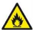
The machine shall not be operated in areas exposed to increased fire or explosion hazard.
Prohibited use
• DO NOT USE THE MITRE SAW FOR CUTTING FIREWOOD!
- Do not operate the machine outside the stated technical restrictions laid down in this manual.
- Do not operate the saw without security devices.
- Do not dismount the saw blade protection.
- Do not use the machine for cutting any other material than wood and wood composite products and plastic.
- Do not manipulate the machine.
12.2 Security instructions
Missing or non-readable security stickers have to be replaced immediately!
The locally applicable laws and regulations may specify the minimum age of the operator and limit the use of this machine!
To avoid malfunction, machine defects and injuries, read the following security instructions!

Read the manual carefully and get familiar with all components before operating the machine for the first time.
This manual contains important information for correct operation of the machine.
This manual is part of the machine and shall be stored for later reference. Add this manual to the machine if handed to 3rd persons for use.
Stick to these Security Warnings and Instructions to reduce the risk of serious injuries.

Assure that the working area is sufficiently lighted!
Keep your work area dry and tidy! An untidy work area may cause accidents. Avoid slippery floor.
Do not overload the machine
Provide good stability and keep balance all times
Avoid abnormal working postures! Make sure you stand squarely and keep balance at all times.
Always stay focused when working. Reduce distortion sources in your working environment. The operation of the machine when being tired, as well as under the influence of alcohol, drugs or concentration influencing medicaments is forbidden.
The plug of an electrical tool must strictly correspond to the socket. Do not use any adapters together with earthed electric tools
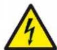
Each time you work with an electrically operated machine, caution is advised! There is a risk of electric shock, fire, cutting injury.
Avoid body contact with earthed
Protect the machine from dampness (causing a short circuit)
Use power tools and machines never in the vicinity of flammable liquids and gases (danger of explosion)
Check the cable regularly for damage
When working with the machine outdoors, use extension cables suitable for outdoor use
Do not use the cable to carry the machine or to fix the work piece
Do not overload the machine
You will work better and safer at specified power range.
Use the correct power tool
Do not use low-power machines for heavy work.
Do not use the power tool for such purposes for which it was not designed. For example do not use hand circular saw for cutting tree limbs or logs.
Respectively trained people only and only one person shall operate the machine. Do not allow other people, particularly children, to touch the machine or the cable. Keep them away from your work area. Make your workshop childproof.

Wear suitable work clothes! Do not wear loose clothing or jewelry as they might be caught and cause severe accidents! Wear a hair net if you have long hair. Loose objects can become entangled and cause serious injuries!


Use personal safety equipment: ear protectors and safety goggles when working with the machine.


Wood dust may contain chemical substances that have a negative impact on personal health. Work on the machine only in well-ventilated areas with suitable dust mask perform!
When working outdoors non-slip footwear is recommended.

Never leave the machine running unattended! Before leaving the working area switch the machine off and wait until the machine stops.
Always disconnect the machine prior to any actions performed at the machine. Avoid unintentional starting

Do not use the machine with damaged switch
Never use the power cord for transportation or manipulation of the machine!

Never leave Before starting the machine remove any adjusting wrenches and screwdrivers
Use a clip or clamping jaws to secure the workpiece
Do not fix the workpiece with your hands
Rotating parts can cause severe cut injuries
Keep the saw blades sharp and clean, so they get stuck less often and are easier to guide
Keep any machine that is not being used out of reach of children
Connect the dust extraction device to
Do not use the cable to remove the plug from the socket.
Protect the cable from heat, oil and sharp edges

text_image
LASERSTRAHLUNG NICHT IN DEN LASER BLICKEN! LASER KLASSE 2 P≤1mW, λ = 650nm EN 60825-1:2007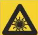
Even Lasers with relatively small output can harm your eyes! Therefore:
Never look directly into the laser or into the laser beam! Never direct the laser beam towards reflecting surfaces, persons and animals.
Do not manipulate the laser device!


Use only saw blades that are suitable for the use with the KAP machine, especially regarding technical parameters and which are tested and comply with the directive EN 847-1.
Deflected, defect or worn saw blades have to be replaced immediately.
Blunt saw blades have to be sharpened or replaced.
Blunt saw blades highly increase the danger of kickback!
Assure yourself that the saw blade is correctly mounted and does not touch the base plate.
Do not stop the saw blade by touching it on the side. This will ruin the drive mechanism.
Do not manipulate or remove the saw blade protecting cover!
Do not fix small workpieces by hand, instead only use the downholder (10).
No material feed, no material removal, no adjustments or other activities when saw blade is running.
Do not position your hands near the saw blade or in a way that they could slip into the cutting line.
Long workpieces have to be supported by the double bar guide.
Take especially care when cutting round workpieces!
Check the workpiece for nails, clamps and other material!
Just cut one workpiece at once. Do not stack or attempt to cut several work-pieces in one cutting operation!
Do not cut firewood
Wear gloves when handling the saw blades and rough materials. It is
recommended that saw blades, whenever practicable be carried in a container.
Make sure that the speed indicated on the saw blade is at least as high as that on the saw speed specified.
Be sure to use only those spacers and screw rings, which are suitable for the purpose specified by the manufacturer.
No Reload, remove or adjust workpieces, or material remains with the machine running!
Do not place hands in near circular saw blade or in a position where they could slip direction circular saw blade!
The use of other application tools and other accessories can mean a risk of personal injury.
Let your power tool repaired by a qualified electrician
The machine does not require extensive maintenance. If malfunctions and defects occur, let it be serviced by trained persons only.


NOTICE
Emergency procedure
A first aid kit in accordance with DIN 13164 should always be readily available for a possible accident. Initiate the violation in accordance with the necessary first aid measures. When requesting support, provide the following details:
-
Place of accident
-
Type of accident
-
Number of injured people
-
Injury type(s)
12.3 Remaining risk factors

WARNING
It is important to ensure that each machine has remaining risks. In the execution of all work (even the simplest) greatest attention is required. A safe working depends on you!
Even if the machine is used as required it is still impossible to eliminate certain residual risk factors totally. The following hazards may arise in connection with the machine's construction and design:
Despite of correct and proper use and maintenance there remain some residual risk factors:
- Risk of injury to the hands / fingers by the rotating tool during operation.
- Risk of injury due to sharp edges of the workpiece, especially in non-fixed with a suitable tool / device workpiece.
- Risk of injury: hair and loose clothing, etc. can be captured and wound up! Safety regulations must be observed with regard to clothing.
- Risk of injury due to contact with live electrical components.
- Risk of injury due to breakage or cracking of the abrasive
- Risk of injury due to dust emissions, treated with harmful agents workpieces
- Risk of injury to the eye by flying debris, even with safety goggles.
- Risk of injury to the hearing by prolonged labor without hearing protection.
These risk factors can be minimized through obeying all security and operation instructions, proper machine maintenance, proficient and appropriate operation by persons with technical knowledge and experience.

WAR NING
This machine produces an electromagnetic field during operation. This field may under some circumstances interfere with active or passive medical implants. To reduce the risk of serious or fatal injury, we recommend persons with medical implants to consult their physician and the medical implant manufacturer before operating this machine!
13 ASSEMBLY
13.1 Delivery content
Please check the product contents immediately after receipt for any eventual transport damage or missing parts. Claims from transport damage or missing parts must be placed immediately after initial machine receipt and unpacking before putting the machine into operation. Please understand that later claims cannot be accepted anymore.
13.2 Assembly
- Place the workpiece hold-down device (10) in the holder provided (see Figure A).
- The workpiece boom (7) mount by mounting the compensation angle (8) between the two outrigger booms. Finally, you put the design into the holes which are positioned laterally on the base plate.
- Insert the suction on the corresponding port on the back of the saw unit. Using the clamping lever to put the dust bag on the suction.
13.3 Transport
When bringing the machine to the workplace you have to prepare it for transport.
These instructions have to be followed prior to every transport of the sliding compound saw
- Disconnect the machine from the power supply.
- Swing the saw arm into the lowest position and lock it in that position with the interlock knob (23).
• Fix the saw arm with the sliding device fixing knob (22). - Lift the machine only at the transport handle (13).
13.4 Workplace requirements
The KAP 305JL sliding compound saw has to be attached to the underground. For this purpose there are 4 borings at the ground plate, two at the front side, two at the back side.
Furthermore you can attach the machine to compound saw stands.

Operating a non attached saw poses a security risk!
14 OPERATION
Device to be operated in a perfect state only. Inspect the device visually every time it is to be used. Check in particular the safety equipment, electrical controls, electric cables and screwed connection for damage and if tightened properly. Replace any damaged parts before operating the device.
14.1 Operation instructions

WAR NING
Perform all machine settings with the machine being disconnected from the power supply!

ATTENTION
- Do not look directly into the laser beam. Never direct the laser beam at people or objects other than the workpiece.
- Do not deliberately point the laser beam at people.
- Only point the laser beam at insensitive workpieces with a dull surface. Wood or rough surfaces are ideal for this. Shiny, reflective surfaces are not suitable for using a laser since the laser beam could be directed at the user by the reflective surfaces.
- Always switch off the laser when you have finished work at the ON/OFF switch for the laser light (38).
- Only switch on the laser beam if there is a workpiece on the mitre saw bench

NOTICE
- Do not use damaged or warped saw blades.
- Replace the worn table insert.
- Select the appropriate saw blade for the material to be cut.
- Warning! Protective equipment must not use for the purpose of transport
- Use the saw only if the safety devices are functional, in good condition and in the provided position.
- Do not remove offcuts or other workpiece parts from the sectional area, as long as the machine with unprotected blade is moving.
- The workpiece must always be clamped to the saw table.
- Before each cutting operation make sure that the machine stands safely.
• Mark the cutting line on the workpiece. - Set the angle of the cutting operation.
- To make a cut from the workpiece hold the laser along the marked line.
14.2 Modes
14.2.1 Angle settings
Tilt adjustment:
- Loosen the fixing knob (18).
- Set the saw arm in order that the tilt angle indicator (36) points exactly at 0° of the measuring scale (19).
• Fix the saw arm in this position by tightening the fixing knob (18). - Bring the saw arm into the lower position and lock it with the interlock knob (23).
- Attach an exact angle measuring device to saw blade side and ground plate. They should have an exact angle of 90^ .
- If not, then you need to adjust the 0^ of the saw arm by adjusting it with the saw arm adjustment screws (N - 37).
- Repeat the procedure until 0^ on indicator is exactly 90^ between saw blade and ground plate.
Swing angle adjustment:
- Loosen the fixing knob (3), operate the fixing lever (4) and swing the saw arm aggregate to the 0° position, let it click into place. You can see the angle at the measuring scale (5).
- Swing the saw arm into the lower position and lock it with the interlock knob (23).
- Attach an exact angle measuring device to saw blade side and the left back fence (1). They should have an exact angle of 90°.
- If not, you need to adjust the back fence guide with the back fence adjustment screws (20) so that angle between saw blade and fence equals 90°.
- Repeat the procedure with the right side back fence.
Adjust the cutting depth
Finally you need to check the cutting depth of the saw.
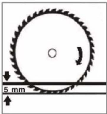
Swing the saw arm down into lowest possible position and check if it touches the ground plate.
The depth stop should be already preset so that the blade reaches into the cutting line slit (2) but has a distance to the ground plate of at least 5mm.
If necessary adjust the depth stop pin (27).
natural_image
Diagram of a circular saw blade with directional arrows indicating motion, no text or symbols presentLaser
The Laser marks the cutting line. After having set all angles and cutting depth, you should fine-tune your laser.
Attach the workpiece to the back fence, fix it with the downholder.
Perform a slot cut on the workpiece so that it gets not cut through entirely.
(See point 5, Slot cut adjustments see point 5.3.3)
Now turn on the laser (ON/OFF Switch 38) and check if the laser beam marks exactly the real cutting line.
If not you need to adjust the whole laser assembly until laser indication matches exactly the actual cutting line.
14.3 Operation
14.3.1 Switch on & prepare to cut
- Connect the machine to the power supply
- Read, understand and apply the security instructions.
• Operate the accelerator lever (24) and wait until the saw blade has reached its full speed. - With the forefinger you now push the security lock lever to the left to unlock the moveable saw blade protection (25).
14.3.2 Switch off
As soon as you release the accelerator knob (24), the motor stops and the saw blade stops within 5-8 seconds.
14.4 Operation modes
14.4.1 Miter cuts
- Ideal for cutting short workpieces in miter and/or bevel angles.
• For miter cuts fix the saw arm on the sliding bars with fixing knob (22). - Place the material to the back fence (1) and fix the material additionally with the downholder (10).
- Prepare to cut according to 5.1, perform the cutting operation.
- Swing the saw arm back up, release the accelerator lever and wait until the electric saw brake stops the saw.
• Now you can take the workpiece away
14.4.2 Sliding cuts
- Sliding cuts are ideal for performing longer cuts
- Fix the material!
• Pull the saw towards your body. - Switch the machine on, wait until saw blade reaches full speed.
- Now swing the saw arm down and let it work its way slowly through the material. Now push the saw arm slowly backwards.
Advantage: If the material cracks or material parts are catapulted, then not towards the operator. Disadvantage: You MUST fix workpiece additionally with downholder (10) to prevent it from kickback.
14.4.3 Slot cuts
- Clap the depth stop (27) to the side so that the adjustment screw (29) touches the depth stop (27) when swinging down the saw arm.
- Adjust the adjustment screw for slut cuts as desired (29).
- Always use well sharpened saw blades. Deflected, cracked or worn saw blades are a security risk and have to be replaced immediately!
- Assure yourself that you do not overload the machine. Use it for operations it is designed for.
- Choose always saw blades where at least 2-3 teeth are simultaneously in the material to achieve a clean cut and to reduce the risk of material kickback.
• For precision miter and bevele cuts you should use a saw blade with at least 60 teeth.
15 MAINTENANCE

ATTENTI ON
Don't clean or do maintenance on the machine while it is still connected to the power supply:
Damages to machine and injuries might occur due to unintended switching on of the machine!
Therefore: Switch the machine off and disconnect it from the power supply before any maintenance works or cleaning is carried out
The machine does not require extensive maintenance. If malfunctions and defects occur, let it be serviced by trained persons only.
Before first operation as well as later on every 100 operation hours you should lubricate all connecting parts (if required, remove beforehand with a brush all swarfs and dust).
Check regularly the condition of the security stickers. Replace them if required.
Check regularly the condition of the machine.
The good condition and perfect adjustment is essential for a smooth and a clean cut.
Store the machine in a closed, dry location.
NOTICE
Clean your machine regularly after every usage – it prolongs the machines lifespan and is a prerequisite for a safe working environment.
Repair jobs shall be performed by respectively trained professionals only!
15.1 Maintenance plan
| Checks and activities to be performed | |
| Loose or lost screws | Prior to every operation |
| Damage of any part | Prior to every operation |
| Saw blade condition | Prior to every operation |
| Clean machine | After every operation |
| Empty dust bag | After every operation |
| Readjust miter and bevel angle, laser; | monthly |
| Sharpen saw blade | When necessary |
| Change saw blade | When worn or defect |
| Change carbon brush | When carbon brush is worn (< 4mm) |
15.2 Change saw blade
In the following causes the blade to be changed:
• You need to change to a different type of blade for better cutting result.
- You replace a worn saw blade by a new one
ATTENTION: Use only saw blades with
√ max. diameter ∅ of 305mm
√ max. thickness of 3mm
√ 25.4 mm inner diameter
√ max. RPM of the saw blade must be at least 4200min ^-1 .
√ Blade quality HSS or better

ATTENTION
To eliminate the risk of cuts you should wear protective gloves when handling the circular saw blade

CAUTION:
To eliminate the hazard of cutting injury, you should wear safety gloves when touching the saw blade.
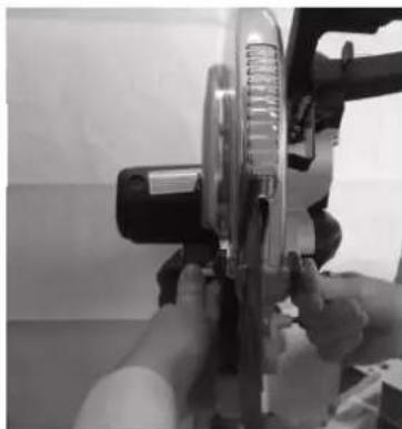
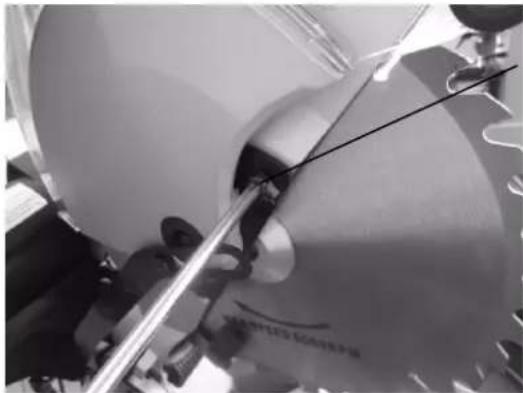
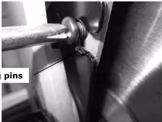
- Swivel the movable circular saw blade guard backwards.
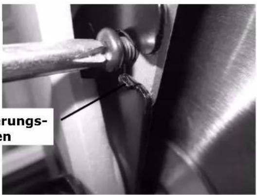
- Turn the locking screw out so far that the safety pin can be pushed past.
If the black guide plate is not easily turn loosen the retainer screw on the left easily.
natural_image
Close-up of a mechanical component with a tool inserted, showing no visible text or symbols.Locking screw
natural_image
Close-up of a metal pipe joint with a labeled 'pins' (no other text or symbols visible)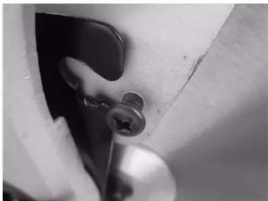
natural_image
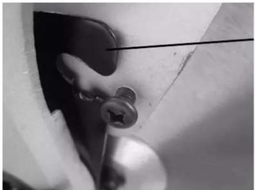
Close-up of a metallic mechanical component with a screw inserted, showing no visible text or symbols.The sheet is pushed upward until the flange bolt is accessible.
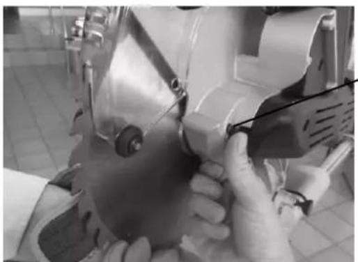
- Press the shaft slightly and rotate the blade until the Spindle interlocksystem clicks.
natural_image
Close-up of hands operating a sewing machine with a tool, no visible text or symbolsspindle interlocksystem
natural_image
Close-up of a gloved hand adjusting a mechanical component with a screw and shaft (no visible text or symbols)• Using the supplied Allen key you-6mm-solve with the flange bolt by turning it clockwise.
NOTE: Left-hand thread!

natural_image
Close-up of a hand adjusting a metallic mechanical component with a tool (no visible text or symbols)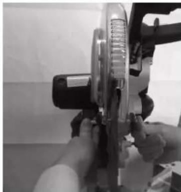
natural_image
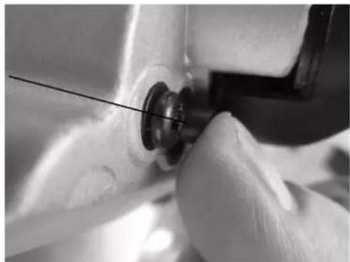
Close-up of hands operating a mechanical device with a circular component (no visible text or symbols)- Remove the flange bolt and flange.
- Remove the blade from the motor shaft.
• Install the new blade onto the spindle and pay attention to the right direction.
- Place the flange on, turn flange screw with the Allen key laid back counterclockwise. Left-hand thread
For Precision miter saw blades are recommended with teeth 60T!
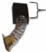
15.3 Change the carbon brush
If your HOLZMANN KAP 305JL motor becomes loud or even does not start anymore, the carbon brushes are probably worn.
Remove with a screwdriver the carbon brush cover (30). If the carbon brush is worn (<4mm) you need to replace the 2 carbon brushes.
Memorize the direction of the carbon brushes when removing them. Take care to insert the new brushes similarly.
natural_image
Close-up of a curved mechanical component with a black block and a small bracket (no visible text or symbols)Min. 4mm
Run the saw for 10 minutes in idle run. Release the accelerator lever and observe the time interval required for the saw blade to stop. If it takes long time to stop ( 20 seconds), then the electric saw blade brake does not work. Let the saw be checked by a professional.
15.4 Storaging
The machine never store outdoors!
Storage permitted only at temperatures between +5 ° and +40 ° C, with at +40 ° C the humidity must not be higher than 60%.
Store in a dry, clean place
15.5 Cleaning
After each workshift the machine has to be cleaned. Remove chips etc. with a suitable tool. Do not remove them by hand (cutting injury!). Remove dust as well.

NOTICE
The usage of certain solutions containing ingredients damaging metal surfaces as well as the use of scrubbing agents will damage the machin surface!
Clean the machine surface with a wet cloth soaked in a mild solution
15.6 Disposal
Do not dispose the machine in residual waste. Contact your local authorities for information regarding the available disposal options. When you buy at your local dealer for a replacement unit, the latter is obliged to exchange your old.
16 TROUBLE SHOOTING
BEFORE YOU START WORKING FOR THE ELIMINATION OF DEFECTS, DISCONNECT THE MACHINE FROM THE POWER SUPPLY.
| Trouble | Possible cause | Solution |
| Engine doesn’t run (or not correctly) | Switch defective | Repair switch |
| Power supply is off | Repair power supply | |
| Carbon brushes defective | Chang carbon brushes | |
| Motor defective | Repair or change motor | |
| Saw blade gets stucked | Blunt saw blade | Sharpening or changing |
| Too hard material or too much pressure | Conform the cutting speed on work piece hardness and engine power | |
| Material kickback | Blunt saw blade | Sharpening or changing |
| Wrong running direction of the saw blade | Control | |
| Wrong cutting angle Wrong mitre angle | Wrong adjusted fence or saw aggregate | Control |
| Saw blade touches the machine bed | Adjusting the cutting depth wrong | Control |
MANY POTENTIAL SOURCES OF ERROR CAN BE CLEARED BY THE EXPERTLY CONNECTION TO THE ELECTRICITY GRID.

NOTICE
Should you in necessary repairs not able to properly to perform or you have not the prescribed training for it always attract a workshop to fix the problem.
17 ESTIMADO CLIENTE (ES)
30.2 Transport stroja
natural_image
Diagram of a circular saw blade with a 5 mm scale indicator, showing rotational motion (no text or symbols beyond measurement)Laser
text_image
R1 L1 R1 C L2 K 230V45 ERSATZTEILE / SPARE PARTS
With original HOLZMANN spare parts you use parts that are attuned to each other shorten the installation time and elongate your products lifespan.
IMP OR TAN T
The installation of other than original spare parts voids the warranty!
So you always have to use original spare parts
When you place a spare parts order please use the service formular you can find in the last chapter of this manual. Always take a note of the machine type, spare parts number and partname. We recommend to copy the spare parts diagram and mark the spare part you need.
You find the order address in the preface of this operation manual.
text_image
Exploded view diagram of a mechanical device with numbered parts for identification and assembly reference.Hereby we declare that the above mentioned machines meet the essential safety and health requirements of the above stated EC directives. Any manipulation or change of the machine not being explicitly authorized by us in advance renders this document null and void.
(applicable from 03.04.2015)
Please consult our troubleshooting section for initial problem solving. Feel free to contact your HOLZMANN reseller or us for Customer Support!
Warranty claims based on your sales contract with your HOLZMANN retailer, including your statutory rights, shall not be affected by this guarantee declaration. HOLZMANN-MASCHINEN grants guarantee according to following conditions:
A) The guarantee covers the correction of deficiencies to the tool/product, at no charge, if it can be verified adequately that the deficiencies were caused by a material or manufacturing fault.
B) The guarantee period lasts 12 months, and is reduced to 6 months for tools in commercial use. The guarantee period begins from the time the new tool is purchased from the first end user. The starting date is the date on the original delivery receipt, or the sales receipt in the case of pickup by the customer.
C) Please lodge your guarantee claims to your HOLZMANN reseller you acquired the claimed tool from with following information:
Original Sales receipt and/or delivery receipt
Service form (see next page) filed, with a sufficient deficiency report
for spare part claims: a copy of the respective exploded drawing with the required spare parts being marked clear and unmistakable.
D) The Guarantee handling procedure and place of fulfillment is determined according to HOLZMANNs sole discretion in accordance with the HOLZMANN retail partner. If there is no additional Service contract made including on-site service, the place of fulfillment is principally the HOLZMANN Service Center in Haslach, Austria.
Transport charges for sending to and from our Service Center are not covered in this guarantee.
E) The Guarantee does not cover:
- Wear and tear parts like belts, provided tools etc., except to initial damage which has to be claimed immediately after receipt and initial check of the product.
- Defects in the tool caused by non-compliance with the operating instructions, improper assembly, insufficient power supply, improper use, abnormal environmental conditions, inappropriate operating conditions, overload or insufficient servicing or maintenance.
- Damages being the causal effect of performed manipulations, changes, additions made to the product.
- Defects caused by using accessories, components or spare parts other than original HOLZMANN spare parts.
- Slight deviations from the specified quality or slight appearance changes that do not affect functionality or value of the tool.
- Defects resulting from a commercial use of tools that - based on their construction and power output - are not designed and built to be used within the frame of industrial/commercial continuous load.
F) Claims other than the right to correction of faults in the tool named in these guarantee conditions are not covered by our guarantee.
G) This guarantee is voluntary. Therefore Services provided under guarantee do not lengthen or renew the guarantee period for the tool or the replaced part.
SERVICE
After Guarantee and warranty expiration specialist repair shops can perform maintenance and repair jobs. But we are still at your service as well with spare parts and/or product service. Place your spare part / repair service cost inquiry by filing the SERVICE form on the following page and send it:
via Mail to info@holzmann-maschinen.at
or via Fax to: +43 7289 71562 4
49 GARANTÍA Y SERVICIO
We observe the quality of our delivered products in the frame of a Quality Management policy.
Your opinion is essential for further product development and product choice. Please let us know about your:
- Impressions and suggestions for improvement.
- experiences that may be useful for other users and for product design
- Experiences with malfunctions that occur in specific operation modes
We would like to ask you to note down your experiences and observations and send them to us via FAX, E-Mail or by post:
Erworben von / purchased from:
E-Mail/ e-mail:
* (Mobil)telefon / (mobile) phone International numbers with country code
Fax
2. Geräteinformationen / tool information
Seriennummer/serial number: ____ *Maschinentype/machine type: ____
Please describe amongst others in the problem: What has cause the problem/defect, what was the last activity before you noticed the problem/defect? For electrical problems: Have you had checked you electric supply and the machine already by a certified electrician?
3. Bitte beachten
/ Additional information
INCOMPLETELY FILLED SERVICE FORMS CANNOT BE PROCESSED! FOR GUARANTEE CLAIMS PLEASE ADD A COPY OF YOUR ORIGINAL SALES / DELIVERY RECEIPT OTHERWISE IT CANNOT BE ACCEPTED. FOR SPARE PART ORDERS PLEASE ADD TO THIS SERVICE FORM A COPY OF THE RESPECTIVE EXPLODED DRAWING WITH THE REQUIRED SPARE PARTS BEING MARKED CLEARLY AND UNMISTAKABLE. THIS HELPS US TO IDENTIFY THE REQUIRED SPARE PARTS FASTLY AND ACCEL- ERATES'THE HANDLING OF YOUR INQUIRY.