HBS 230HQ - Saw Holzmann - Free user manual and instructions
Find the device manual for free HBS 230HQ Holzmann in PDF.
User questions about HBS 230HQ Holzmann
0 question about this device. Answer the ones you know or ask your own.
Ask a new question about this device
Download the instructions for your Saw in PDF format for free! Find your manual HBS 230HQ - Holzmann and take your electronic device back in hand. On this page are published all the documents necessary for the use of your device. HBS 230HQ by Holzmann.
USER MANUAL HBS 230HQ Holzmann
12.1 Intended Use....31
12.2 Security instructions 32
12.3 Remaining risk factors 33
13 ASSEMBLY 34
13.1 Initial activities....34
13.1.1 Delivery content .... 34
13.1.2 Workplace requirements .... 34
13.1.3 Preparation of the surfaces....34
13.2 Electric connection.... 34
13.3 Assembly 35
14 OPERATION 37
14.1 Operating notes 37
14.2 Settings....37
14.2.1 Swivel table 37
14.2.2 Aligning the saw band / tilt adjustment....37
14.2.3 Blade tension 38
14.2.4 Blade guide 39
14.3 Operation....40
14.3.1 Start / Stop....40
14.3.2 Miter gauge....40
14.3.3 Using push stick....41
14.3.4 Saw....41
14.3.5 Connecting to dust collector 41
15 MAINTENANCE 42
15.1 Maintenance plan 42
15.1.1 After each workshift: 42
15.2 Changing the band saw blade....43
15.3 Changing the v-ribbed belt....44
15.4 Cleaning 45
15.5 Disposal 45
16 TROUBLE SHOOTING 46
17 PRÉFACE (FR) 47
18 CARACTERISTIQUES TECHNIQUES 48
35.3 Bediening....94
35.3.1 Starten / Stoppen 94
35.3.5 Afzuiging....95
36 ONDERHOUD 96
EN EC-CONFORM - This product complies with the EC-directives.
EN READ THE MANUAL! Read the user and maintenance manual carefully and get familiar with the controls in order to use the machine correctly and to avoid injuries and machine defects.
EN ATTENTION! Ignoring the safety signs and warnings applied on the machine as well as ignoring the security and operating instructions can cause serious injuries and even lead to death.
CZ OCHRANNÉ PROSTŘEDKY
EN Operation with gloves forbidden!
EN Stop and pull out the power plug before any break and engine maintenance!
EN Operation with jewelry forbidden!
EN Operation with tie forbidden!
EN Operation with long hair forbidden!
EN Warning about cut injuries!
EN Warning of rotating parts!
EN Protect from moisture!
ES Proteger de la humedad!
text_image
Exploded view diagram of a mechanical device with numbered parts for identificationnatural_image
Technical line drawing of a mechanical device with no visible text or symbols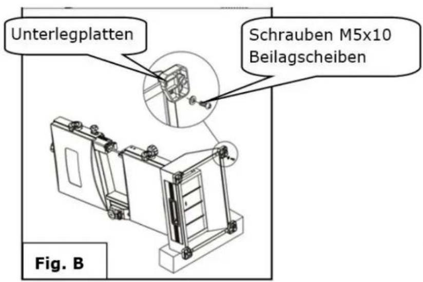
natural_image
Technical line drawing of a mechanical device with multiple ports and mounting base (no text or symbols)natural_image
Technical line drawing of a mechanical assembly with a slide and adjustment mechanism (no text or symbols)natural_image
Simple line drawing of a tool gripping a rectangular object (no text or symbols)7.3.4 Sägen
natural_image
Technical line drawing of a mechanical device with no visible text or symbolsnatural_image
Technical line drawing of a mechanical assembly with a lever and bracket (no text or symbols)2.
natural_image
Close-up of a hand holding a black cable inserted into a mechanical component (no visible text or symbols)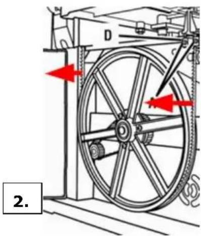
natural_image
Mechanical diagram showing a wheel assembly with red arrows indicating motion direction (no text or symbols)3.
natural_image
Close-up of a mechanical component with a central hub and mounting holes (no visible text or symbols)5.
natural_image
Close-up of a hand holding a black plastic component next to a white industrial machine (no visible text or symbols)8.4 Reinigung
natural_image
Symbol of a trash bin with crossed lines indicating no waste, and a solid black rectangle below (no text or labels)9 FEHLERBEHEBUNG
This manual contains information and important instructions for the installation and correct use of the wood band saw HBS 230HQ.
Following the usual commercial name of the device (see cover) is substituted in this manual with the name "machine".
This manual is part of the product and shall not be stored separately from the product. Save it for later reference and if you let other people use the product, add this instruction manual to the product.

Please read and obey the security instructions!
Before first use read this manual carefully. It eases the correct use of the product and prevents misunderstanding and damages of product and the user's health.
Due to constant advancements in product design, construction pictures and content may diverse slightly. However, if you discover any errors, inform us please.
Technical specifications are subject to changes!
Please check the product contents immediately after receipt for any eventual transport damage or missing parts.
Claims from transport damage or missing parts must be placed immediately after initial product receipt and unpacking before putting the product into operation.
Please understand that later claims cannot be accepted anymore.
Copyright
© 2016
This document is protected by international copyright law. Any unauthorized duplication, translation or use of pictures, illustrations or text of this manual will be pursued by law. Court of jurisdiction is the Landesgericht Linz or the competent court for 4170 Haslach, Austria!
Customer service contact
text_image
Exploded view diagram of a mechanical device with numbered parts for identification| 1 | Band saw | 1 | 8 | Lifting Handle | 1 |
| 2 | Fence | 1 | 9 | Foot A | 2 |
| 3 | Table assembly | 1 | 10 | Foot B | 2 |
| 4 | Miter gauge | 1 | 11 | Pan head screw and washer | 8 |
| 5 | Push stick | 2 | 12 | M6 hex nut | 1 |
| 6 | Wrench 8 - 10mm | 4 | 13 | Hook | 1 |
| 7 | Hex wrench 2,5 - 4 - 6 mm | 3 |
11.2 Technical Details
| Motor power | 300 W |
| Voltage | 230V / 50Hz |
| Cutting-capacity | 90 mm |
| Thread Width | 228 mm |
| Cutting-speed | 635 m/min |
| Table size | 300 x 300 mm |
| Blade size | 1575 x 3 - 10 mm |
| Pivoting range Table | 0 - 45° |
| Dimensions L x W x H | 490 x 380 x 840 mm |
| Weight | 20 kg |
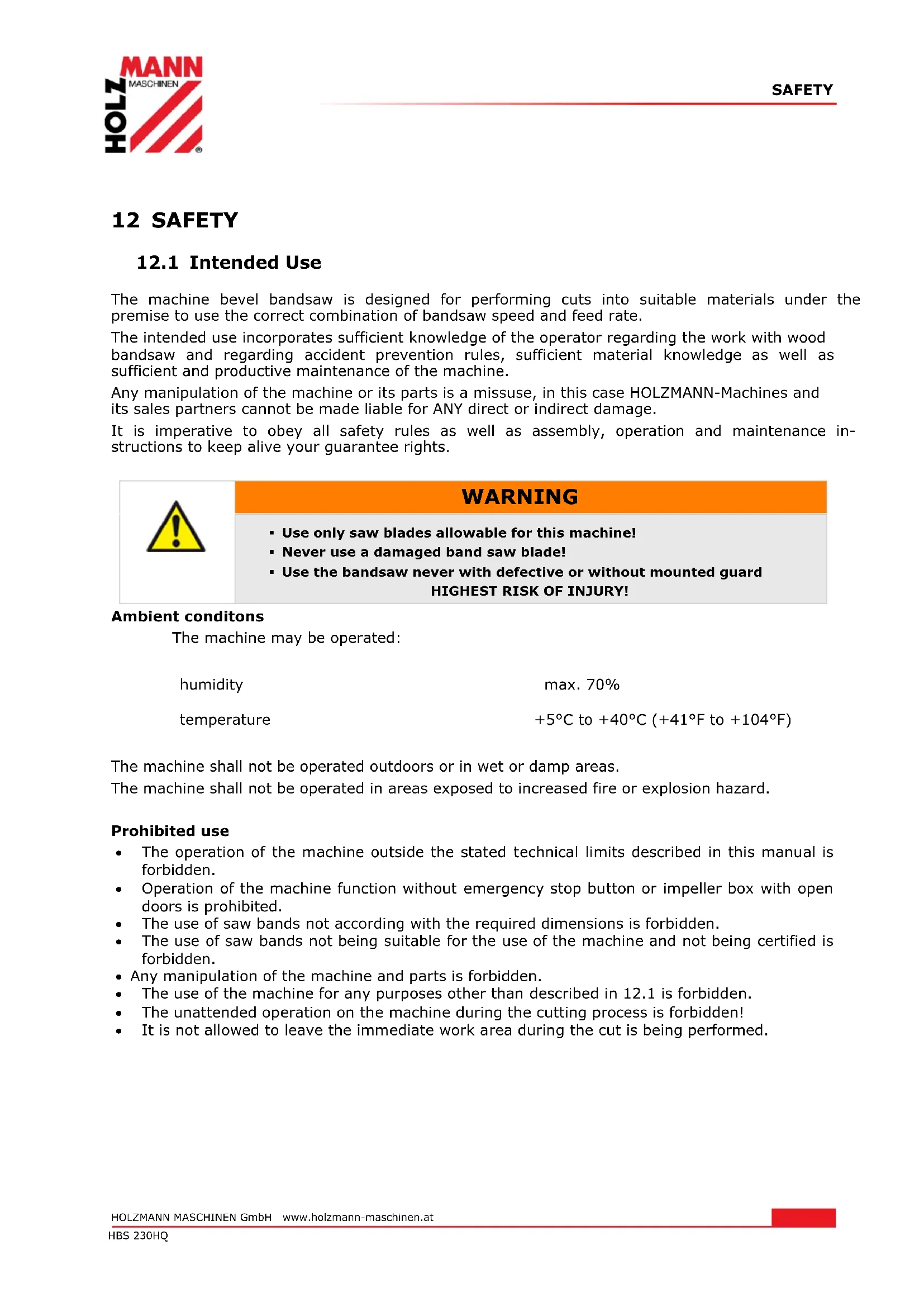
12 SAFETY
12.1 Intended Use
The machine bevel bandsaw is designed for performing cuts into suitable materials under the premise to use the correct combination of bandsaw speed and feed rate.
The intended use incorporates sufficient knowledge of the operator regarding the work with wood bandsaw and regarding accident prevention rules, sufficient material knowledge as well as sufficient and productive maintenance of the machine.
Any manipulation of the machine or its parts is a missuse, in this case HOLZMANN-Machines and its sales partners cannot be made liable for ANY direct or indirect damage.
It is imperative to obey all safety rules as well as assembly, operation and maintenance instructions to keep alive your guarantee rights.

WARNING
- Use only saw blades allowable for this machine!
- Never use a damaged band saw blade!
- Use the bandsaw never with defective or without mounted guard HIGHEST RISK OF INJURY!
Ambient conditons
The machine may be operated:
humidity
max. 70%
temperature
$$ + 5 ^ {\circ} \mathrm{C} \text { to } + 4 0 ^ {\circ} \mathrm{C} (+ 4 1 ^ {\circ} \mathrm{F} \text { to } + 1 0 4 ^ {\circ} \mathrm{F}) $$
The machine shall not be operated outdoors or in wet or damp areas.
The machine shall not be operated in areas exposed to increased fire or explosion hazard.
Prohibited use
- The operation of the machine outside the stated technical limits described in this manual is forbidden.
- Operation of the machine function without emergency stop button or impeller box with open doors is prohibited.
• The use of saw bands not according with the required dimensions is forbidden. - The use of saw bands not being suitable for the use of the machine and not being certified is forbidden.
- Any manipulation of the machine and parts is forbidden.
- The use of the machine for any purposes other than described in 12.1 is forbidden.
• The unattended operation on the machine during the cutting process is forbidden! - It is not allowed to leave the immediate work area during the cut is being performed.
12.2 Security instructions
Missing or non-readable security stickers have to be replaced immediately!
To avoid malfunction, machine defects and injuries, read the following security instructions!
The locally applicable laws and regulations may specify the minimum age of the operator and limit the use of this machine!

- Keep your work area dry and tidy! An untidy work area may cause accidents. Avoid slippery floor.

• Make sure the work area is lighted sufficiently
- Do not use the machine outdoors!
- Avoid abnormal working postures! Make sure you stand squarely and keep balance at all times.
- Keep away from the running saw band!

• Always stay focused when working. Reduce distortion sources in your work-ing environment. The operation of the machine when being tired, as well as under the influence of alcohol, drugs or concentration influencing medicaments is forbidden.
• The machine shall be operated by respectively trained persons only.
- Do not allow other persons, particularly children, to touch the machine or the cable. Keep them away from your work area.
• Make your workshop childproof.

- Wear suitable work clothes! Do not wear loose clothing or jewellery as they might get caught in moving parts and cause severe accidents! Wear a hair net if you have long hair.

- Use personal safety equipment: ear protectors, safety goggles, when working on dusty jobs.

- Never leave the machine running unattended! Before leaving the working area switch the machine off and wait until the saw band stops.
• Always disconnect the machine prior to any actions performed at the machine.
- Avoid unintentional starting

• Each time you work with an electrically operated sawing apparatus, caution is advised! There is a risk of electric shock, fire, cutting injury;
- Protect the machine from dampness (causing a short circuit)
- Use power tools and machines never in the vicinity of flammable liquids and gases (danger of explosion)
- Check the cable regularly for damage
- Protect the cable from heat, oil and sharp edges.
- Avoid body contact with earthed
- Use appropriate holding device when sawing logs
- The upper blade guide to keep as close to the workpiece
- Attach the fence to the lower half of the table for inclined table
• Workpieces while working safely hold and guide
- Remove the sawed-off or jammed workpieces only at standstill of the saw blade
• Make sure that no excessive concentration of dust is produced. Use suitable dust extraction equipment!
- Remove before editing foreign matter (nails, screws) from the workpiece
- For straight cuts against the rip fence push stick should be used


12.3 Remaining risk factors

WARNING
It is important to ensure that each machine has remaining risks. In the execution of all work (even the simplest) greatest attention is required. A safe working depends on you!
Even if the machine is used as required it is still impossible to eliminate certain residual risk factors totally. The following hazards may arise in connection with the machine's construction and design:
- Damage to hearing, when sound levels in workshop add up to a total level being harmful. Wear ear-muffs to eliminate this risk factor.
• Respiratory damages due to harmful emissions of wood dust.
• Severe cutting injuries at contact with the running band in the uncovered cutting zone. - Injuries (cuts) when changing the band. Wear safety gloves when changing the saw band.
- Injury from catapulted workpieces or parts of workpieces.
- Injury through breaking saw band
• Electrocution through contact with internal leading machine parts
This risk factors can be minimized through obeying all security and operation instructions, proper machine maintenance, proficient and appropriate operation by persons with technical knowledge and experience.
13 ASSEMBLY
13.1 Initial activities
13.1.1 Delivery content
Please check the product contents immediately after receipt for any eventual transport damage or missing parts. Claims from transport damage or missing parts must be placed immediately after initial machine receipt and unpacking before putting the machine into operation. Please understand that later claims cannot be accepted anymore.
13.1.2 Workplace requirements
The workplace has to fulfill the requirements stated.
The ground has to be even, in level and hard. It must be suitable at least to weight it with double weight per square meter than the machines net weight.
The chosen workplace must have access to a suitable electric supply net hat complies with the machines requirements.
The machine must be placed in a way that at least 0.8m room free space around the machine. For longer workpieces sufficient additional place before and behind the machine should be calculated.
13.1.3 Preparation of the surfaces
Uncoated metal machine parts have been insulated with a greasy layer to inhibit corrosion.
This layer has to be removed. You can use standard solvents that do not damage the machine surface.

NOTICE
Do not use solvents based on nitrite, aggressive solvents like break cleaners or scrubbing agents!
These damage the machine surface.
13.2 Electric connection
AT TENTION
When working with non-grounded machines: Severe injury or even death may arise though electrocution!
Therefore: The machine must be operated at a grounded power socket!
• The electrical connection of the machine is ready for operation on a grounded outlet!
- The feed mains through with min. 16A be hedged.
- Check whether the mains voltage matches the requirements of the machine.
- A damaged cable must be replaced immediately!
13.3 Assembly
The machine is delivered pre-assembled.
For transport reasons, the saw table can be assembled by the customer.
1. Attach the foot to band saw.
- Put down the machine on a timber like at the picture.
- Attach the foots to band saw by using pan head screw and washer.
- Place the band saw on a workbench for next assembly.
natural_image
Technical line drawing of a mechanical device with no visible text or symbols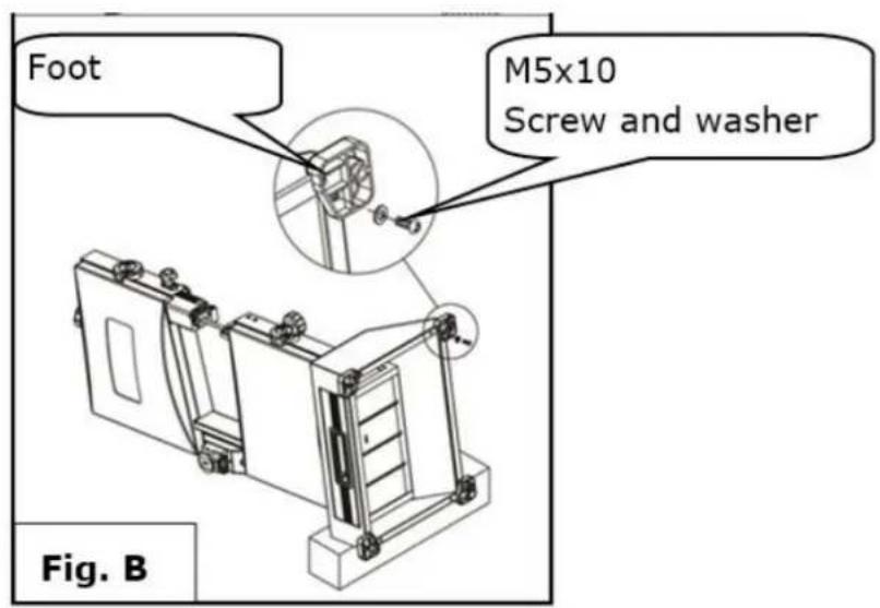
text_image
Foot M5x10 Screw and washer Fig. B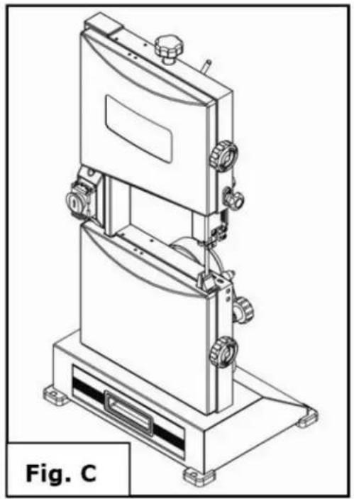
natural_image
Technical line drawing of a mechanical device with multiple ports and a base platform (no text or symbols)2. Fix the lifting handle on top of band saw.
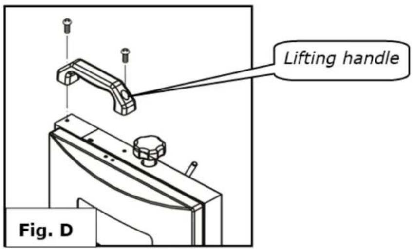
text_image
Lifting handle Fig. D3. Mounting table assembly
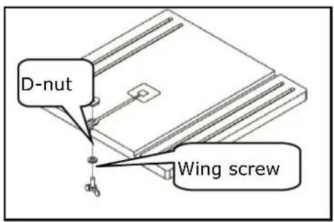
Remove the D-nut, washers, and wing screw on the saw table.
Slide the saw table past the blade and through the slot moving to the frame, pulling the angle adjustment knob away from the saw frame, Align the teeth on the saw table bracket into the teeth on the angle adjustment knob. Release the knob.
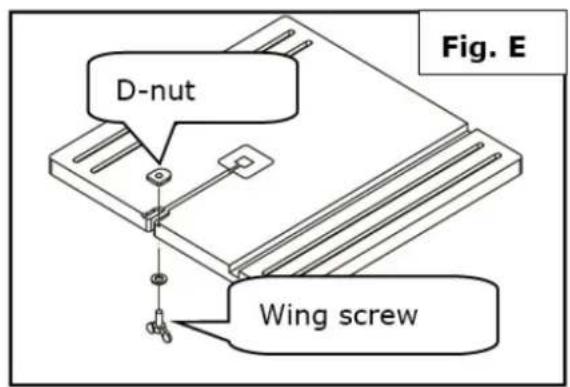
text_image
D-nut Wing screw Fig. E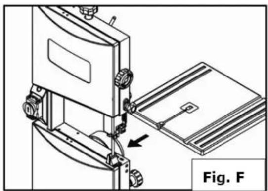
natural_image
Technical line drawing of a mechanical assembly with a bracket and mounting base, labeled Fig. F (no text or symbols on the diagram itself)- Fit the pins on the frame into the slots of the saw table bracket.
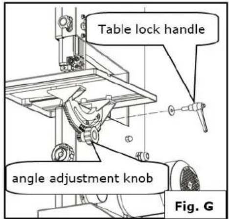
- Assemble the flat washer and table lock handle. Tighten the saw table to the saw frame by turning the table lock lever clockwise.
- Attach the D-nut, washers, and wing screw to the saw table
text_image
Table lock handle angle adjustment knob Fig. G- Secure the hook with M6 hex nut to the frame.
- Place push stick onto the hook
text_image
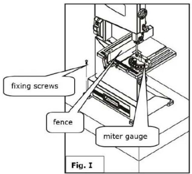
fixing screws fence miter gauge Fig. I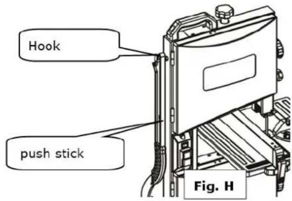
text_image
Hook push stick Fig. HFix the band saw to a workbench by using four thread forming screws (not provide)
- Place the fence and miter gauge onto the table.
14 OPERATION
14.1 Operating notes

WARNING
Perform all machine settings with the machine being disconnected from the power supply!

ATTENTION
TAKE ATTENTION when cutting long workpieces without additional support!
Hazard of machine damage and injuries through upbouncing workpiece.
Therefore: always support long overhanging workpieces additionally

NOT ICE
Let the engine run full speed when you begin to cut a work a workpiece
14.2 Settings
14.2.1 Swivel table
- Loosen the lock with the quick-release lever.
- Swing the table to the angle adjustment knob to the desired angle.
- Fix the table with the table locking handle in front of the first section
- The desired angle is expediently to be checked by test cuts
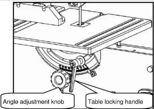
text_image
Angle adjustment knob Table locking handle14.2.2 Aligning the saw band / tilt adjustment
If the bandsaw blade is not running in the center on the rollers, is corrected by adjusting the inclination of the caster the position of the saw blade.
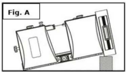
- Open the upper and lower rollers cover (Fig. A)
- Turn by hand slowly in the upper roller clockwise. The saw blade to run centered on the rubber pads of the caster. If this is not the case, the inclination angle of the upper Sägebandrolle must be corrected.
- Loosen the lock (Fig.B) using the rotary knob.
- Turn to control the roller by hand in a clockwise direction around the barrel of the saw band. Note that the running direction of the saw blade from top to bottom. Correct the running of the saw blade by turning the knob left or right.
- Now check the running of the saw band on the lower roller. It should lie in its entire width on the rubber pad. Correct the run until the saw band on the upper Sägebandrolle running centered.
After the adjustments fix again everything and close both covers
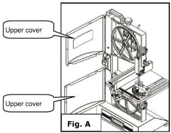
text_image
Upper cover Upper cover Fig. A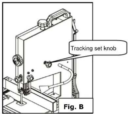
text_image
Tracking set knob Fig. B
NOTICE
After setting and before switch on turn the upper wheel roll by hand a few times to see if the band saw runs out of the rollers. If this is the case, the blade must be aligned again.
14.2.3 Blade tension

WAR NING
Check the blade tension before any operation

NOT ICE
Too much tension: The band saw blade can break Too less tension: The band saw blade can slip and stop
The ideal voltage is in the range between worktable and the upper saw band at about 2mm. If this is not the case, loosen or tighten the bandsaw blade as follows:
- Clamping by turning the knob clockwise.
- Relax by turning it counterclockwise.
After the end of the work shift the saw band is to relax with the quick-release lever again.
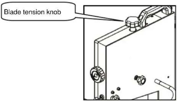
text_image
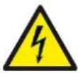
Blade tension knob14.2.4 Blade guide
The blade guide is used to adjust the distance from the band saw blade to the guide bearing.
 | WARNING |  |
| Do not adjust the sawband guidance when the machine is working!Heavy injuries on hands and arms are possible!Sawband guidance can be adjusted only after the sawband direction and the sawband tension has been proofed.Before you adjust the sawband guidance switch off the machine and wait until the sawband is standing completely still. |  |
Upper blade guide
The height of the guide must be adjusted prior to each work so that the saw band about 10 mm ends to the workpiece.
- The Locking knob loosen and adjust the appropriate level with the Adjusting knob and then secure again.
text_image
Adjusting knob Locking knob Guide bearing C B A Saw blade guide bearing 0.50mm 1 - 2 mm thrust bearing guide bearing 0.5 mm- Loosen the screw (A), and adjust guide bearing position, so that guide bearing is positioned 1 or 2mm from teeth of blade. Retighten the bolt (A).
- Loosen the screw (B), and adjust trust bearing to a position of 0.5mm from rear of blade. Retighten the knob (B).
- Loosen the socket head screw (C), and adjust guide bearing to a position 0.5mm away from blade. Retighten the socket head screw (C).
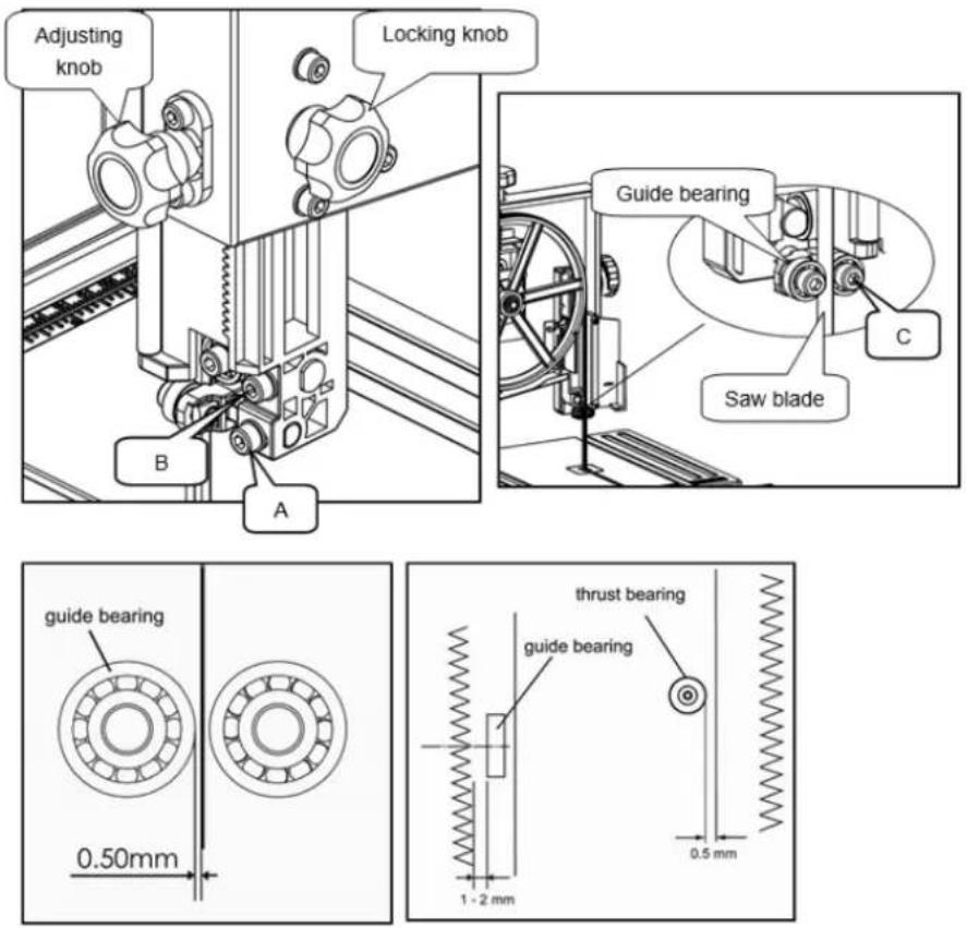
Lower blade guide (Fig.1)
The lower blade guide must be readjusted after each band saw blade change or tracking adjustment.
- Through the hole (B) and (E), use hex wrench to loosen socket bolts, adjust guide block (D) and thrust bearing (C) just like adjusting upper blade guide.
- Loosen the screw (A), and adjust the guide bearing to a position 0.5mm away from blade. Retighten the screw (A).
text_image
A B D C E14.3 Operation
14.3.1 Start / Stop
- To turn ON or OFF the machine, press the main switch
• To use LED-light, turn ON the light switch.
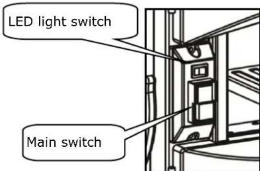
text_image
LED light switch Main switch14.3.2 Miter gauge
- To use the miter gauge fence, slide it into the slot provided.
- To adjust the angle of the miter cut, loosen lock, move the miter gauge to the desired position (60°) and fix him afterwards.
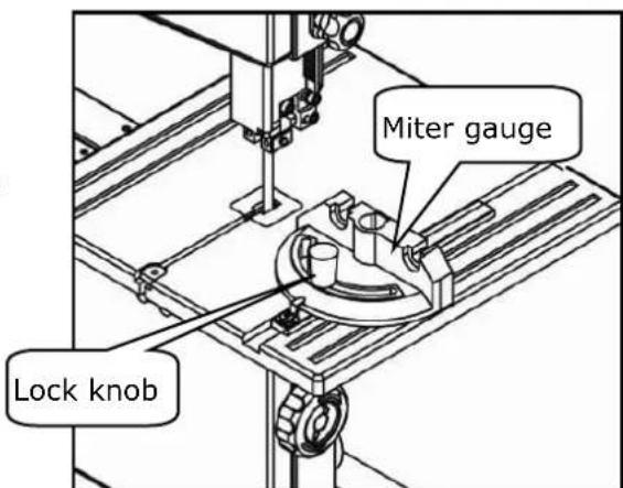
text_image
Miter gauge Lock knob14.3.3 Using push stick

WARNING
The push stick protects against contact with the saw band
- The push stick must always be used when the distance between Band saw blade and and rip fence is less than 150mm.
- If the sliding floor is not used to deposit on the hook
- If damaged, the push stick must be immersed immediately
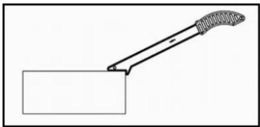
natural_image
Simple line drawing of a tool gripping a rectangular block (no text or symbols)14.3.4 Saw
- Put the workpiece securely on the table on
- Observe the workpiece from start to finish exactly
- Saw the section without interruption in a train
• Turn off the machine after work immediately
14.3.5 Connecting to dust collector
At an extraction suction can be connected. If this is not required, the wood chips collect in the loading below the lower tape roll.
This dust drawer is to be emptied after use of the machine.
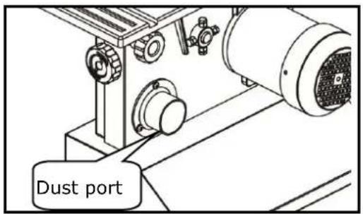
text_image
Dust port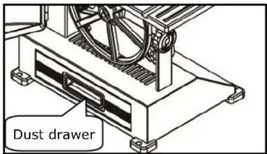
text_image
Dust drawer15 MAINTENANCE

ATTENTI ON
Don't clean or do maintenance on the machine while it is still connected to the power supply:
Damages to machine and injuries might occur due to unintended switching on of the machine!
Therefore: Switch the machine off and disconnect it from the power supply be-fore any maintenance works or cleaning is carried out
The machine does not require extensive maintenance. If malfunctions and defects occur, let it be serviced by trained persons only.
Before first operation as well as later on every 100 operation hours you should lubricate all connecting parts (if required, remove beforehand with a brush all swarfs and dust).
Check regularly the condition of the security stickers. Replace them if required.
Check regularly the condition of the saw band and the saw band guide.
The good condition and perfect adjustment of the guiding rollers is essential for a smooth band guidance and a clean cut.
Store the machine in a closed, dry location.
NOTICE
Clean your machine regularly after every usage – it prolongs the machines lifespan and is a pre-requisite for a safe working environment.
Repair jobs shall be performed by respectively trained professionals only!
15.1 Maintenance plan
15.1.1 After each workshift:
- Relaxing the saw band.
- Disconnect the machine from the power supply.
- Clean the machine entirely.
- Lubricate the blade guide with light machine oil a bit.
15.2 Changing the band saw blade


WARNING
Wear gloves when handling with saw blades! HIGHEST RISK OF CUTTING INJURY!
Before changing the blade, check that the machine is swiched off and disconet from the power supply
ATTENTION: Take care to install the saw band correctly!
Check the direction of the teething


- Unscrew the D-nut and wing screw on the worktable.
- Open the upper and the lower cover.
- Set the upper saw band guide in the lowest position
- Open the cover of upper guide assembly
- Loosen the quick release handle
- Remove the band saw blade from the machine.
- Insert a new bandsaw blade with the right direction on the rubber tyres on the band saw wheels.
- Check the declared adjustment.
text_image
D-nut Wing screw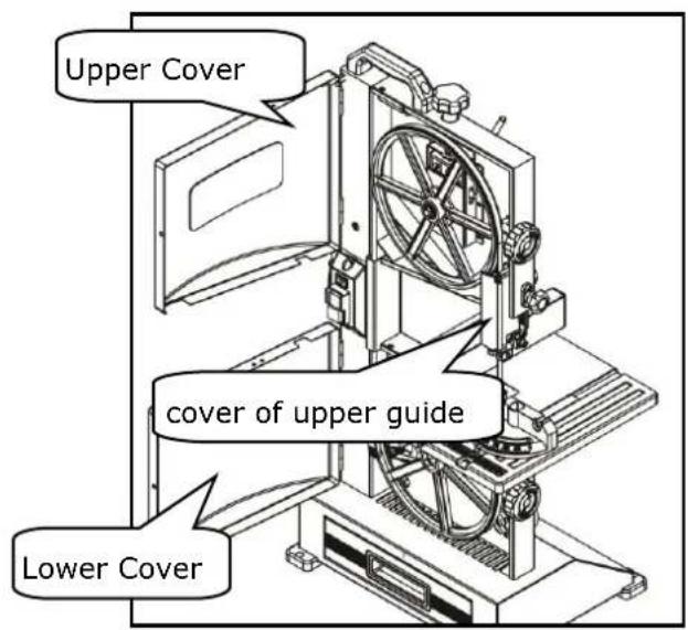
text_image
Upper Cover cover of upper guide Lower Cover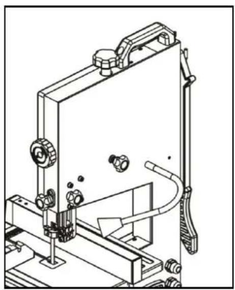
natural_image
Technical line drawing of a mechanical device with no visible text or symbols15.3 Changing the v-ribbed belt
1.
- Relax the saw blade with the blade tension knob.
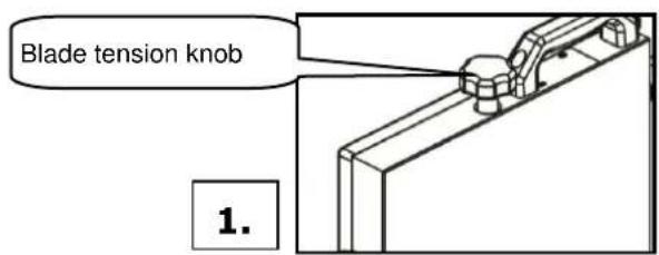
text_image
Blade tension knob 1.2.
- Open the lower saw band cover and remove the bandsaw blade from the drive shaft.
- WARNING: gloves for the sawblade use!
natural_image
Close-up of a hand holding a black cable inserted into a mechanical component (no visible text or symbols)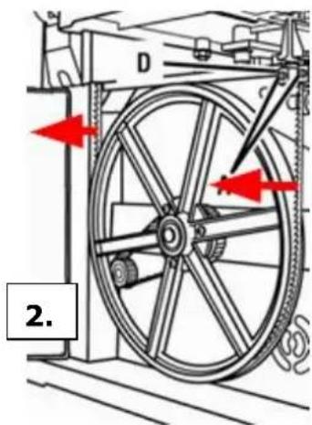
text_image
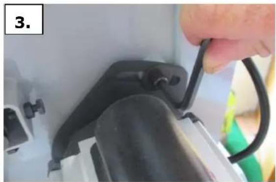
2.3.
Loosen the v-ripped belt on the motor bracket with an Allen key and relaxing.
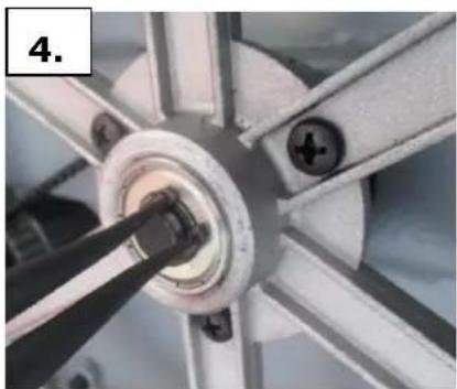
4.
- Remove the outer retaining ring with the outer retaining ring pliers.
natural_image
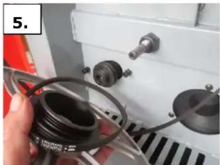
Close-up of a mechanical component with a central hub and multiple arms (no visible text or symbols)5.
- Remove the drive roller of the drive shaft.
- Replace v-ripped belt and put the drive back to the drive shaft.
- Attach retaining ring
- Insert v-ripped belt in the desired pulleys.
- ripped v-belt tension on the engine mount.
- Bandsaw blade on the drive roller hang up and check the saw band in on good leadership.
- saw band tension with knob.
- Close Sawband cover
natural_image
Close-up of a hand holding a black plastic roller with attached components, next to a white industrial machine (no visible text or symbols)15.4 Cleaning
After each workshift the machine has to be cleaned. Remove chips etc. with a suitable tool. Do not remove them by hand (cutting injury!). Remove dust as well.

NOTICE
The usage of certain solutions containing ingredients damaging metal surfaces as well as the use of scrubbing agents will damage the machin surface!
Clean the machine surface with a wet cloth soaked in a mild solution
15.5 Disposal
Do not dispose the machine in residual waste. Contact your local authorities for information regarding the available disposal options. When you buy at your local dealer for a replacement unit, the latter is obliged to exchange your old
16 TROUBLE SHOOTING
Disconnect the machine from the power supply prior to any checks performed at the machine itself!
| Trouble | Possible cause | Solution |
| Saw stops or will not start | Overload trippedSaw unpluggedFuse blown or circuit breaker trippedCord damaged | Allow motor to cool and reset by pushing off switchCheck all power connectionsChange fuse or reset circuit breakeChange cable |
| Does not make accurate 45° or 90° cuts | Stop not adjusted correctlyAngle pointer not set accuratelyMiter gauge out of adjustment | Check band with square and adjust stopCheck band with square and adjust pointerAdjust miter gauge |
| Band wanders during cut | Fence not aligned with bandWarped woodExcessive feed rateIncorrect band for cut | Check and adjust fenceSelect another piece of woodReduce feed rateChange band to correct type |
| Saw makes unsatisfactory cuts | Dull bandBand mounted wrongGum or pitch on bandIncorrect band for cutGum or pitch on table | Replace bandTeeth should point downRemove band and cleanChange band to correct typeClean table |
| Band does not come up to speed | Extension cord too light or tooLow shop voltage | Replace with adequate size cordContact your local electric company |
| Saw vibrate excessively | Base on uneven floorBad v-beltBent pulleyImproper motor mountingLoose hardware | Reposition on flat level surfaceReplace v-beltReplace pulleyCheck and adjust motorTighten hardware |
| Saw band runs in opposite direction | 2 of the 3 leading phases are switched whether in Plug or socket | Shut off machine immediately. Let the connection to supply circuit be corrected by an electrician! |
MANY MALFUNCTIONS AND DEFECTS CAN BE AVOIDED BY LETTING THE MACHINE BE CONNECTED TO YOUR POWER SUPPLY BY A CERTIFIED ELECTRICIAN
17 PRÉFACE (FR)
Cher Client,
text_image
Exploded view diagram of a mechanical device with numbered parts for identificationnatural_image
Technical line drawing of a mechanical assembly with labeled section 'Fig. A' (no other text or symbols)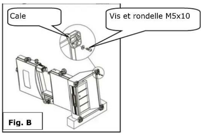
text_image
Cale Vis et rondelle M5x10 Fig. B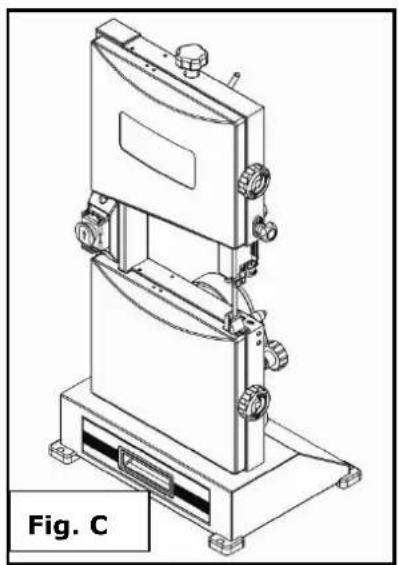
natural_image
Technical line drawing of a mechanical device with labeled Fig. C (no text or symbols on the diagram itself)natural_image
Technical line drawing of a mechanical device with a close-up view showing a component being inserted (no text or symbols present)text_image
Galets 0.50mm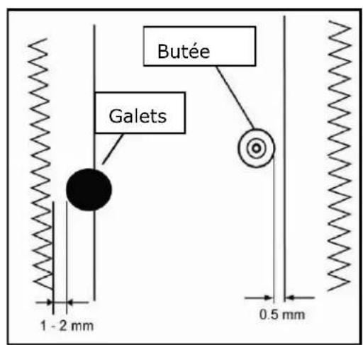
text_image
Butée Galets 1 - 2 mm 0.5 mmtext_image
Technical diagram of a mechanical device with labeled components A, B, C, D, and E21.3 Fonctionnement
natural_image
Technical line drawing of a mechanical assembly or cabinet with no visible text or symbolsnatural_image
Simple line drawing of a tool interacting with a rectangular block (no text or symbols)21.3.4 Coupe
natural_image
Technical line drawing of a mechanical device with no visible text or symbolsnatural_image
Close-up of a mechanical component with a central hub and four arms, no visible text or symbols5.
natural_image
Close-up of a hand holding a black plastic hose and coiled cable inside a white industrial machine (no visible text or symbols)22.4 Nettoyage
text_image
Exploded view diagram of a mechanical device with numbered parts for identificationnatural_image
Technical line drawing of a mechanical assembly labeled Fig. A, showing internal components and mounting brackets (no text or symbols beyond label)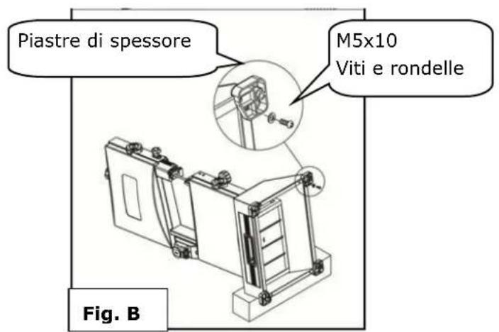
natural_image
Technical line drawing of a mechanical device with no visible text or symbolsnatural_image
Technical line drawing of a mechanical assembly with no visible text or symbolsnatural_image
Simple line drawing of a tool gripping a rectangular object (no text or symbols)28.3.4 Segare
natural_image
Technical line drawing of a mechanical device with no visible text or symbolsnatural_image
Close-up of a hand holding a black cable inserted into a mechanical component (no visible text or symbols)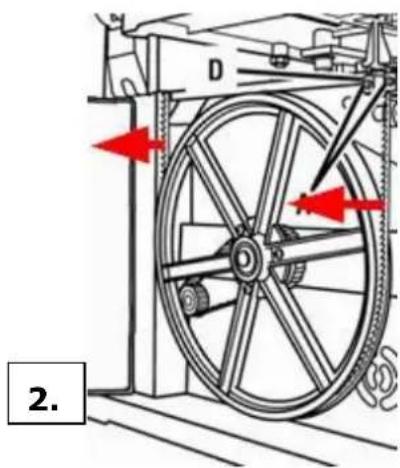
text_image
D 2.3.
natural_image
Close-up of a mechanical component with a central hub and mounting holes (no visible text or symbols)5.
natural_image
Close-up of a hand holding a black plastic component next to a white industrial machine (no visible text or symbols)29.4 Pulizia
text_image
Exploded view diagram of a mechanical device with numbered parts for identificationHOOGSTE RISICO VAN LETSELS!
Arbeidsvoorwaarden
natural_image
Technical line drawing of a mechanical device labeled Fig. A, showing internal components and mounting brackets (no text or symbols beyond label)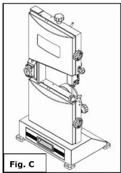
natural_image
Technical line drawing of a mechanical device with multiple ports and mounting base (no text or symbols)natural_image
Technical line drawing of a mechanical device with a close-up view showing a component being inserted (no text or symbols present)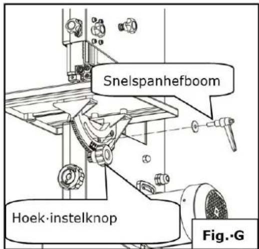
text_image
Snelspanhefboom Hoek-instelknop Fig.·G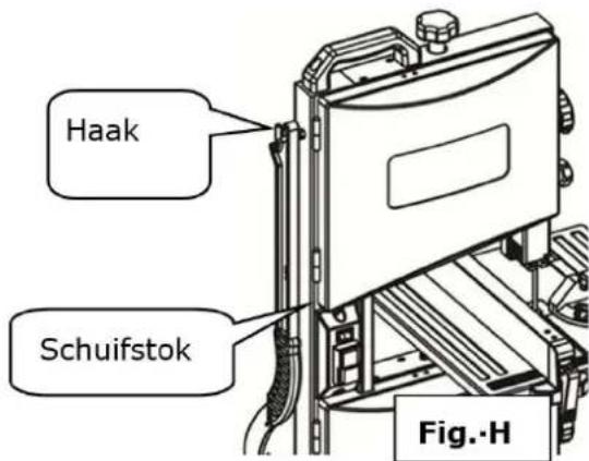
text_image
Haak Schuifstok Fig.-Hnatural_image
Simple line drawing of a tool gripping a rectangular object (no text or symbols)35.3.4 Zagen
text_image
Afzuigadapter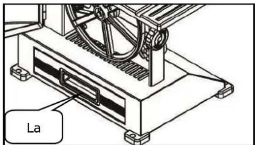
text_image
La36 ONDERHOUD

OPGELET
natural_image
Technical line drawing of a mechanical device with no visible text or symbolsnatural_image
Close-up of a hand holding a black cable or wire attached to a mechanical device (no visible text or symbols)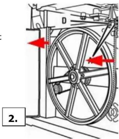
text_image
D 2.3.
natural_image
Close-up of a mechanical wheel assembly with visible gears and mounting holes (no text or symbols)5.
natural_image
Close-up of a hand holding a black plastic hose with attached components, next to a white industrial machine (no visible text or symbols)36.4 Reiniging
With original HOLZMANN spare parts you use parts that are attuned to each other shorten the installation time and elongate your products lifespan.
IMP OR TAN T
The installation of other than original spare parts voids the warranty!
So you always have to use original spare parts
When you place a spare parts order please use the service formular you can find in the last chapter of this manual. Always take a note of the machine type, spare parts number and partname. We recommend to copy the spare parts diagram and mark the spare part you need.
You find the order address in the preface of this operation manual.
text_image
Exploded view diagram of a refrigerator with numbered parts and labeled connectors| No. | Description | Qty | No. | Description | Qty |
| 1 | Knob | 1 | 93 | saw guide block | 1 |
| 2 | flat washer | 1 | 94 | flat washer | 2 |
| 3 | pressure spring | 1 | 95 | bolt | 2 |
| 4 | bolt | 1 | 96 | flat washer | 2 |
| 5 | support | 1 | 97 | bolt | 2 |
| 6 | bolt | 1 | 98 | ||
| 7 | round pin | 1 | 98,01 | blade block | 1 |
| 8 | nut | 2 | 98,02 | bolt | 1 |
| 9 | nut | 1 | 98,03 | blade cover | 1 |
| 10 | spring washer | 1 | 98,04 | blade block | 1 |
| 11 | wheel support | 1 | 98,05 | pressure spring | 1 |
| 12 | wheel shaft | 1 | 98,06 | flat washer | 1 |
| 13 | bearing | 4 | 98,07 | bolt | 1 |
| 14 | upper disc wheel | 1 | 98,08 | bearing studdle | 1 |
| 15 | retaining ring | 4 | 98,09 | flat washer | 1 |
| 16 | retaining ring | 2 | 98,10 | bearing | 1 |
| 17 | wheel rim | 2 | 98,11 | bolt | 1 |
| 18 | bolt | 4 | 99 | fixing nut | 1 |
| 19 | sheeting | 2 | 100 | fixing plate | 1 |
| 20 | nut | 4 | 101 | flat washer | 2 |
| 21 | upper wheel cover | 1 | 102 | flat washer | 1 |
| 22 | blade | 1 | 103 | bolt | 2 |
| 23 | lower wheel cover | 1 | 104 | locking handle | 1 |
| 24 | nut | 2 | 105 | flat washer | 2 |
| 25 | cushion cover | 2 | 106 | pressure spring | 1 |
| 26 | bolt | 2 | 107 | adjustment handle | 1 |
| 27 | lower disc wheel | 1 | 108 | bolt | 1 |
| 28 | bolt | 3 | 109 | eccentric wheel | 1 |
| 29 | driven gear | 1 | 110 | bolt | 2 |
| 30 | lower wheel shaft | 1 | 111 | handle seat | 1 |
| 30,1 | locknut | 1 | 112 | washer | 1 |
| 31 | nut | 4 | 113 | eccentric wheel shaft | 1 |
| 32 | bolt | 4 | 114 | bolt | 1 |
| 33 | handle | 1 | 115 | handle | 1 |
| 33,1 | bolt | 2 | 116 | mite gauge assembly | 1 |
| 34 | bolt | 4 | 116,1 | know | 1 |
| 35 | microswitch cover | 2 | 116,2 | flat washer | 1 |
| 36 | microswitch | 2 | 116,3 | mite gauge | 1 |
| 37 | microswitch box | 2 | 116,4 | bolt | 1 |
| 38 | nut | 4 | 116,5 | flat washer | 1 |
| 39 | body | 1 | 116,6 | pointer | 1 |
| 40 | switch cover | 1 | 116,7 | sliding bar | 1 |
| 41 | terminal | 1 | 117 | table insert | 1 |
| 42 | tension disc | 1 | 118 | table assembly | 1 |
| 43 | bolt | 2 | 118,1 | table | 1 |
| 44 | switch cover plate | 1 | 118,2 | nut | 1 |
| 45 | bolt | 2 | 118,3 | flat washer | 1 |
| 46 | switch | 1 | 118,4 | bolt | 1 |
| 47 | switch | 3 | 118,5 | rotation seat | 1 |
| 48 | spring washer | 2 | 118,6 | nut | 1 |
| 49 | tooth washer | 2 | 118,7 | bolt | 1 |
| 50 | bolt | 2 | 118,8 | flat washer | 4 |
| 51 | nut | 1 | 118,9 | bolt | 4 |
| 52 | flat washer | 2 | 119 | limit shaft sleeve | 2 |
| 53 | spacer bush | 1 | 120 | bolt | 2 |
| 54 | brush | 1 | 121 | flat washer | 1 |
| 55 | bolt | 1 | 122 | handle | 1 |
| 56 | dust drawer | 1 | 123 | pointer | 1 |
| 57 | dust drawer handle | 1 | 124 | flat washer | 1 |
| 58 | steel ball spring | 1 | 125 | bolt | 1 |
| 59 | steel ball | 1 | 126 | rotation handle | 1 |
| 60 | fixing sleeve | 1 | 127 | pressure spring | 1 |
| 61 | bolt | 2 | 128 | bolt | 1 |
| 62 | foot pad | 2 | 129 | motor | 1 |
| 63 | bolt | 8 | 130 | sponge ring | 1 |
| 63,1 | flat washer | 8 | 131 | gear | 1 |
| 64 | foot pad | 2 | 132 | flat washer | 1 |
| 65 | belt | 1 | 133 | bolt | 1 |
| 66 | dust port | 1 | 134 | flat washer | 2 |
| 67 | bolt | 3 | 92 | adjustment handle | 1 |
| 68 | locknut | 2 | 135 | bolt | 2 |
| 69 | handle | 2 | 136 | power line | 1 |
| 70 | bolt | 2 | 137 | inner wire | 2 |
| 71 | bolt | 1 | 138 | pipe | 2 |
| 72 | bearing | 1 | 139 | wrench | 1 |
| 73 | flat washer | 1 | 140 | wrench | 1 |
| 74 | bearing studdle | 1 | 141 | push stick | 1 |
| 75 | bolt | 4 | 142 | hook | 1 |
| 76 | bearing | 4 | 143 | nut | 1 |
| 77 | saw guide block | 1 | 144 | fence assembly | |
| 77,1 | flat washer | 4 | 144,01 | fence | 1 |
| 77,2 | nut | 4 | 144,02 | shrapnel | 1 |
| 78 | saw guide block | 1 | 144,03 | panel | 1 |
| 79 | bolt | 2 | 144,04 | pull rod | 1 |
| 80 | flat washer | 2 | 144,05 | locking handle | 1 |
| 81 | bolt | 2 | 144,06 | fence seat | 1 |
| 82 | lower protecting cover | 1 | 144,07 | end cup | 1 |
| 83 | flat washer | 2 | 144,08 | bolt | 2 |
| 84 | bolt | 2 | 144,09 | locknut | 1 |
| 85 | strain relief | 2 | 144,10 | bolt | 4 |
| 86 | guide block | 1 | 145 | nut | 1 |
| 87 | bolt | 1 | 146 | flat washer | 1 |
| 88 | adjustment gear | 1 | 147 | LED driver | 1 |
| 89 | adjustment handle seat | 1 | 148 | bolt | 1 |
| 90 | flat washer | 1 | 149 | nut | 1 |
| 91 | bolt | 2 | 150 | LED light | 1 |
40 EG-KONFORMITÄTSERKLÄRUNG/CE-CERTIFICATE OF CONFORMITY

Inverkehrbringer / Distributor
Hereby we declare that the above mentioned machines meet the essential safety and health requirements of the above stated EC directives. Any manipulation or change of the machine not being explicitly authorized by us in advance renders this document null and void.
(applicable from 26.09.2016)
Please consult our troubleshooting section for initial problem solving. Feel free to contact your HOLZMANN reseller or us for Customer Support!
Warranty claims based on your sales contract with your HOLZMANN retailer, including your statutory rights, shall not be affected by this guarantee declaration. HOLZMANN-MASCHINEN grants guarantee according to following conditions:
A) The guarantee covers the correction of deficiencies to the tool/product, at no charge, if it can be verified adequately that the deficiencies were caused by a material or manufacturing fault.
B) The guarantee period lasts 12 months, and is reduced to 6 months for tools in commercial use. The guarantee period begins from the time the new tool is purchased from the first end user. The starting date is the date on the original delivery receipt, or the sales receipt in the case of pickup by the customer.
C) Please lodge your guarantee claims to your HOLZMANN reseller you acquired the claimed tool from with following information:
Original Sales receipt and/or delivery receipt
Service form (see next page) filed, with a sufficient deficiency report
for spare part claims: a copy of the respective exploded drawing with the required spare parts being marked clear and unmistakable.
D) The Guarantee handling procedure and place of fulfillment is determined according to HOLZMANNs sole discretion in accordance with the HOLZMANN retail partner. If there is no additional Service contract made including on-site service, the place of fulfillment is principally the HOLZMANN Service Center in Haslach, Austria.
Transport charges for sending to and from our Service Center are not covered in this guarantee.
E) The Guarantee does not cover:
- Wear and tear parts like belts, provided tools etc., except to initial damage which has to be claimed immediately after receipt and initial check of the product.
- Defects in the tool caused by non-compliance with the operating instructions, improper assembly, insufficient power supply, improper use, abnormal environmental conditions, inappropriate operating conditions, overload or insufficient servicing or maintenance.
- Damages being the causal effect of performed manipulations, changes, additions made to the product.
- Defects caused by using accessories, components or spare parts other than original HOLZMANN spare parts.
- Slight deviations from the specified quality or slight appearance changes that do not affect functionality or value of the tool.
- Defects resulting from a commercial use of tools that - based on their construction and power output - are not designed and built to be used within the frame of industrial/commercial continuous load.
F) Claims other than the right to correction of faults in the tool named in these guarantee conditions are not covered by our guarantee.
G) This guarantee is voluntary. Therefore Services provided under guarantee do not lengthen or renew the guarantee period for the tool or the replaced part.
SERVICE
After Guarantee and warranty expiration specialist repair shops can perform maintenance and repair jobs. But we are still at your service as well with spare parts and/or product service. Place your spare part / repair service cost inquiry by filing the SERVICE form on the following page and send it:
via Mail to info@holzmann-maschinen.at
or via Fax to: +43 7289 71562 4
43 GARANTIE ET SERVICE
We observe the quality of our delivered products in the frame of a Quality Management policy.
Your opinion is essential for further product development and product choice. Please let us know about your:
- Impressions and suggestions for improvement.
- experiences that may be useful for other users and for product design
- Experiences with malfunctions that occur in specific operation modes
We would like to ask you to note down your experiences and observations and send them to us via FAX, E-Mail or by post:
Please describe amongst others in the problem: What has cause the problem/defect, what was the last activity before you noticed the problem/defect? For electrical problems: Have you had checked you electric supply and the machine already by a certified electrician!
3. Bitte beachten
Additional information
INCOMPLETELY FILLED SERVICE FORMS CANNOT BE PROCESSED! FOR GUARANTEE CLAIMS PLEASE ADD A COPY OF YOUR ORIGINAL SALES / DELIVERY RECEIPT OTHERWISE IT CANNOT BE ACCEPTED. FOR SPARE PART ORDERS PLEASE ADD TO THIS SERVICE FORM A COPY OF THE RESPECTIVE EXPLODED DRAWING WITH THE REQUIRED SPARE PARTS BEING MARKED CLEARLY AND UNMISTAKABLE. THIS HELPS US TO IDENTIFY THE REQUIRED SPARE PARTS FASTLY AND ACCEL- ERATES THE HANDLING OF YOUR INQUIRY.