Phoenix Charger - Battery charger VICTRON ENERGY - Free user manual and instructions
Find the device manual for free Phoenix Charger VICTRON ENERGY in PDF.
| Product type | Automatic high-frequency battery charger |
| Brand | Victron Energy |
| Model | Phoenix Charger |
| Mains power supply | 120-240 VAC, single-phase |
| Nominal output voltage | 12 V or 24 V depending on model |
| Max charge current | Up to 50 A for model 12/50, 30 A for 12/30, etc. |
| Charging technology | Self-adaptive 4-step (Bulk, Absorption, Float, BatterySafe) |
| Number of battery outputs | Two main outputs + one auxiliary output (trickle-charge) |
| Protections | Against short circuits, overheating, reverse polarity (LED), output fuses |
| Galvanic isolation | Yes, thanks to a galvanically isolated output stage |
| Thermal compensation | Yes, via supplied temperature sensor |
| Remote voltage sensing | Yes, via +V-sense and -V-sense terminals (recommended) |
| Remote control | Optional via Phoenix Charger Control panel |
| User settings | Bulk current, Absorption voltage, Float voltage, battery type, etc. (via buttons or remote panel) |
| Compatible battery types | Open lead, gel, AGM, sealed (adjustable) |
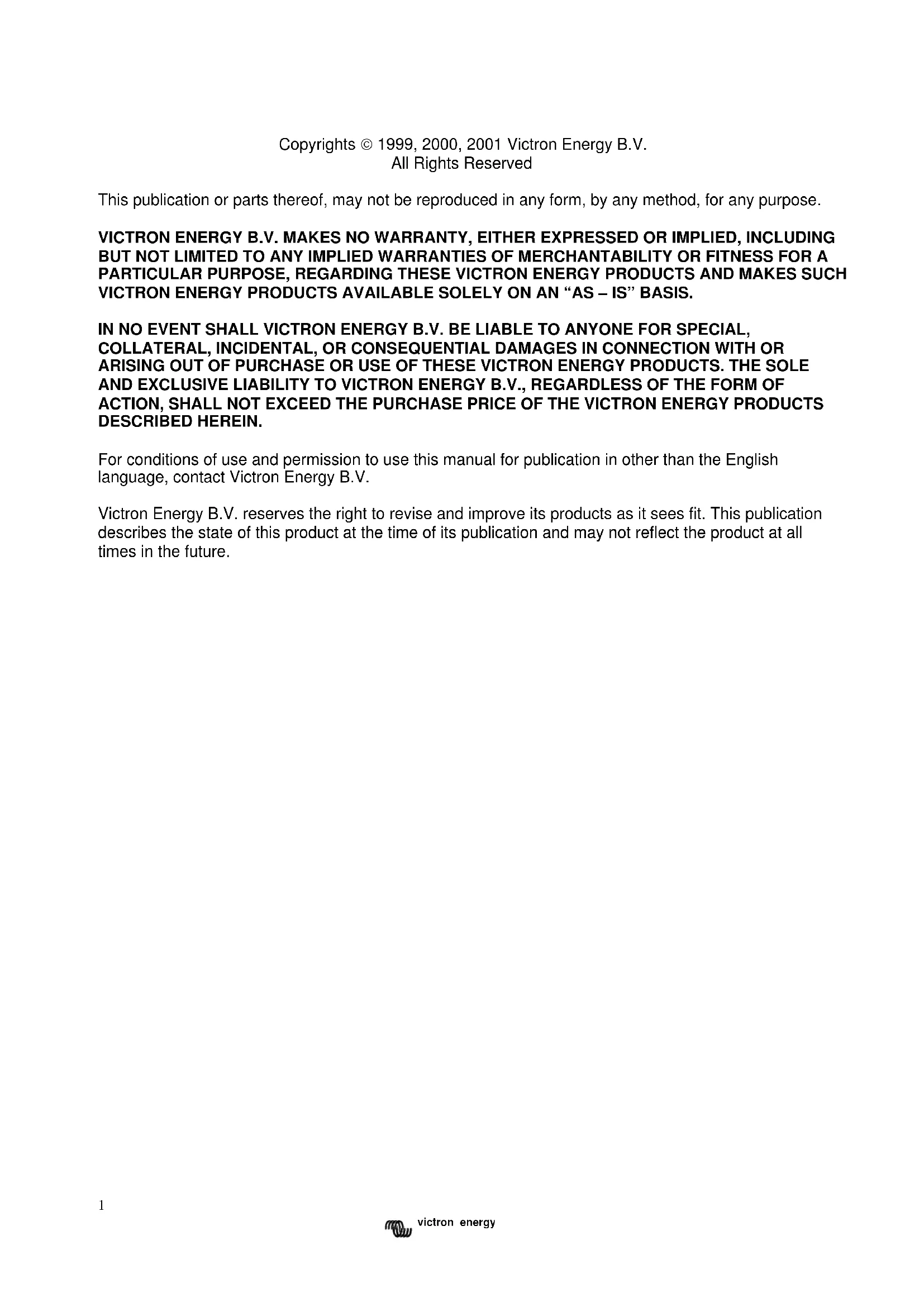
| Dimensions (approx. model 12/30) | 325 x 160 x 110 mm (L x W x H) |
| Weight | Approximately 3 to 5 kg depending on model |
| Storage temperature | -20°C to +60°C |
| Safety class | Category I (grounding mandatory) |
| Maintenance | No user-serviceable parts. Clean with a dry cloth. Disconnect before maintenance. |
Frequently Asked Questions - Phoenix Charger VICTRON ENERGY
User questions about Phoenix Charger VICTRON ENERGY
0 question about this device. Answer the ones you know or ask your own.
Ask a new question about this device
Download the instructions for your Battery charger in PDF format for free! Find your manual Phoenix Charger - VICTRON ENERGY and take your electronic device back in hand. On this page are published all the documents necessary for the use of your device. Phoenix Charger by VICTRON ENERGY.
USER MANUAL Phoenix Charger VICTRON ENERGY
USER MANUAL GEBRUIKSAANWIJZING MODE D'EMPLOI GEBRAUCHSANWEISUNG INSTRUZIONE PER L'USO INSTRUKTIONSBOG ΚΑΘΑΡΙΣΤΗ ΓΨΗΛΗΣ ΠΙΕΣΗΣΚΑΘΑΡΙΣΤΗ ΓΨΗΛΗΣ INSTRUKSJONSHÅNDBOK MANUAL DE INSTRUÇÕES MANUAL DE INSTRUCCIONES ANVÄNDARMANUAL
Phoenix Charger
12/30
12/50
24/16
24/25
Copyrights © 1999, 2000, 2001 Victron Energy B.V.
All Rights Reserved
This publication or parts thereof, may not be reproduced in any form, by any method, for any purpose.
VICTRON ENERGY B.V. MAKES NO WARRANTY, EITHER EXPRESSED OR IMPLIED, INCLUDING BUT NOT LIMITED TO ANY IMPLIED WARRANTIES OF MERCHANTABILITY OR FITNESS FOR A PARTICULAR PURPOSE, REGARDING THESE VICTRON ENERGY PRODUCTS AND MAKES SUCH VICTRON ENERGY PRODUCTS AVAILABLE SOLELY ON AN "AS – IS" BASIS.
IN NO EVENT SHALL VICTRON ENERGY B.V. BE LIABLE TO ANYONE FOR SPECIAL, COLLATERAL, INCIDENTAL, OR CONSEQUENTIAL DAMAGES IN CONNECTION WITH OR ARISING OUT OF PURCHASE OR USE OF THESE VICTRON ENERGY PRODUCTS. THE SOLE AND EXCLUSIVE LIABILITY TO VICTRON ENERGY B.V., REGARDLESS OF THE FORM OF ACTION, SHALL NOT EXCEED THE PURCHASE PRICE OF THE VICTRON ENERGY PRODUCTS DESCRIBED HEREIN.
For conditions of use and permission to use this manual for publication in other than the English language, contact Victron Energy B.V.
Victron Energy B.V. reserves the right to revise and improve its products as it sees fit. This publication describes the state of this product at the time of its publication and may not reflect the product at all times in the future.
SAFETY AND REGULATORY INFORMATION
General
- Review related documentation of this product to familiarise yourself with safety markings and instructions before you operate the equipment.
- This product has been designed and tested in accordance with international standards. Only use the equipment for the intended purpose of application.
- WARNING: RISK OF ELECTRIC SHOCK. The product is used in conjunction with a permanent energy source (battery). Even if the equipment is switched off, dangerous electrical voltages may appear at the in- and/or output terminals. Always disconnect AC power and battery before maintaining or servicing the product.
A Ground Fault Circuit Interruptor (GFCI) must be installed in the AC supply circuit.
- There are no user-serviceable parts inside. Do not remove the frontplate or operate the product without the frontplate fitted. Refer all servicing to qualified personnel.
- Never use the product in locations where there is danger of gas- or dust explosions. Consult your supplier to ensure that the product is intended for use in conjunction with the battery. Always apply the battery manufacturer's safety instructions.
- Caution: never carry heavy loads without assistance.
- Explosive gases can be generated during charging of a lead-acid battery. Prevent open flame and sparks. Take care of sufficient ventilation during charging.
- Never try to recharge non-rechargeable batteries.
- The on/off switch at the front panel of this battery charger does not isolate the main circuits.
- A double-pole switch with a minimum contact distance of 3mm must be incorporated in the fixed mains input wiring of the installation
Installation
- The installation of this product must be performed by qualified personnel.
- Always refer to the installation section in the operator's manual before applying power to the equipment.
-
This is a Safety Class I product (provided with a protective earthing terminal). An uninterruptible safety earth ground must be provided at the AC in/output terminals. An additional grounding point is located at the outside of the product. Whenever it is likely that the grounding protection has been impaired, the product must be made inoperative and secured against any unintended operation; refer to qualified service personnel.
-
Make sure that fuses and circuit breakers are provided in the connecting wires. Never replace a safety component by a different type. Consult the manual for determining the correct component.
- Make sure that all cables and wiring in the installation are anchored such that the conductors are relieved from strain and twisting.
- Before applying power, verify that the available power source matches the configuration settings of the product as described in the manual.
- Ensure that the environmental conditions are suitable for operation of the equipment. Never operate the product in a wet or in a dusty environment.
• Always allow enough free space around the product for ventilation and make sure that ventilation vents are not blocked. - Be sure that the demanded power does not exceed the capacity of the product.
- This device is a continuous duty automatic charger for rechargeable open, sealed and gel lead acid batteries (max. 12 x 2V cells)
- For supply connection use wires suitable for at least 75^ (167°F).
- CAUTION: Replace defective cords or wires immediately.
Transport and storage
- When storing or transporting the product make certain that mains power and battery leads are disconnected.
- No liability can be accepted for any transport damage when equipment is shipped in non-original packaging.
- Store the product in a dry location, storage temperature must be between -20^ and 60^ .
- Refer to the battery manufacturer manual concerning transport, storage, charging, recharging and disposal of the battery.
DESCRIPTION
Technology
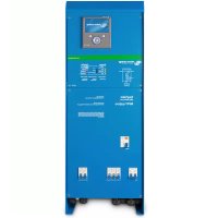
The Phoenix Charger is a fully high-frequency switched battery charger. The input is electronically powerfactor corrected by the first powerstage.
The next stage gives provision for galvanic isolation and a perfect DC voltage at the output terminals.
A very accurate charging state of the battery is guaranteed because the charging process is microcontroller regulated.
The internal electronic parts are protected against moisture and dirt by means of a special coating, which assures a long lifetime of your battery charger.
Two high-capacity batteries and an additional low-capacity battery can be charged with this charger.
Adaptive Charging
The new Phoenix Charger uses the Adaptive Charging Characteristic. The Adaptive Charging Characteristic distinguishes from other charging characteristic on several topics. The main 3 topics are Rapid Charging, Battery Safe Mode and All Season Mode.
Generally speaking the Phoenix Charger will adapt to the connected batteries.
Rapid charging
In the first stage, the bulk phase, of the charging cycle the batteries are charged with higher current then traditional charging methods. The bulk phase will stop at the point where the battery voltage will be 14,4V or 28,8V. From here the absorption phase will start.
Based on the measured bulk time the length of the absorption time will be calculated. For this the charger micro-controller will monitor several parameters of the battery.
BatterySafe mode
But what if your battery needs a higher absorption voltage? The charger will gradually raise the applied voltage to the battery until it reaches the set absorption voltage. This phase we call the BatterySafe Mode. It will safe your battery from destruction by overcharging.
The Phoenix Charger is temperature compensated. The charger will recalculate different values based on the battery temperature.
All Season mode
For periods were you do not use your batteries and the mains is applied to the charger, the Phoenix Charger will reduce its float voltage. By doing this we reduce the gassing in your battery so they will not run dry after a longer period of not using your battery.
To keep your batteries in shape the Phoenix Charger will raise the applied voltage once a week. This we call the repetitive absorption.
Operation
The battery charger charges the battery with a 4-stage adaptive charging characteristic, see specifications at the back for details. It can remain connected to the battery continuously, without increased gas formation, caused by overcharging, taking place.
The charger can be used for different types of batteries but the default settings are for Sonnenschein A200 dryfit gel batteries. See specifications for other pre-programmed battery types.
For use with other types of batteries please contact your battery supplier to inform you about the right charging voltages. If necessary let the Phoenix Charger be readjusted.
The full charging current of the Phoenix Charger is divided in two main outputs.
An extra output with limited charge capacity is available to charge a starter battery for example. The charger is protected against short-circuit at the outputs and too high ambient temperature.
Temperature sensor
The Phoenix Charger is factory shipped with a temperature sensor. Its function is to measure the battery temperature and adjust the charging voltages accordingly. By this means superiour charging is achieved and a longer lifetime of the battery is assured.
Voltage sense
Using the Voltage sense connection will compensate the battery cable loss.
Controls
The Phoenix Charger will start charging by switching it ON with the switch at the front panel. One of the LED's at the front will indicate the progress of charge state:
Battery is less then 80% charged.
Battery is approximately charged for 80%. If Bulk LED is illuminating as well the set absorption voltage has not yet been reached (Battery Safe Mode).
Battery is fully charged and will be kept charged with trickle charge.
An output fuse is defective or the ambient temperature of the charger is too high.

text_image
Bulk Absorption Float FailureThe Phoenix Charger will stop charging by switching it OFF with the switch at the front panel.
Equalize a traction set
This is done at a higher voltage than most DC-equipment can handle so all consumer electronics should be disconnected before equalizing the battery.
- Put the charger in off position. Switch ON-OFF-ON within 2 seconds.
- You'll see all the LED's flashing 5 times. After the 5th time all LEDs illuminate in sequence:
- Bulk –switch OFF-ON when this LED lights up. Now the charger increases its voltage up to 1 Volt above Absorption voltage for a 12V model or 2 Volts for a 24V model. The maximum current in this mode is limited to 14 of the adjusted maximum charge current. The charger will stay in this mode for 1 hour and then switches to Float mode. Equalizing will only work with an already charged battery. If the battery voltage remains too low (see specs) for >60 seconds the charger switches to Bulk mode and continues charging according normal charging characteristic.
Force to Absorption mode for fixed time
In certain circumstances it can be desirable to charge the battery occasionally with Absorption voltage for a fixed time.
- Put the charger in off position. Switch ON-OFF-ON within 2 seconds.
- You'll see all the LED's flashing 5 times. After the 5th time a sequence starts:
- Bulk –wait.
- Absorption –switch OFF-ON when this LED lights up.
Now the charger will stay in Absorption mode for the default or adjusted fixed Absorption time.
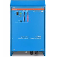
Remote control
The Phoenix Charger can be remote controlled optionally. With the Phoenix Charger Control all indicators can be seen and additionally the charging current. With this remote control it is possible to temporarily limit the charging current. This could be useful in case of a low current mains connection in combination with other utility equipment.
TROUBLESHOOTING
| Problem | Possible cause | Solution |
| Failure LED illuminates | The output fuses are defect | Return the product to your dealer |
| The ambient temperature of the charger is too high | Put the charger in a cool and well ventilated environment | |
| Charger does not function | The mains voltage is not ok | Measure the mains voltage and make it within specs |
| The input fuse is defect | Return the product to your dealer | |
| The battery doesn't get fully charged | A bad battery connection | Check the battery connections |
| The Absorption voltage is wrongly adjusted | Consult your battery supplier and electrician and have the charging voltage adjusted | |
| The float voltage is wrongly adjusted | ||
| The battery capacity is too large | Make sure the charger matches the battery capacity | |
| The output fuses are defect | Return the product to your dealer | |
| The battery is being overcharged | The Absorption voltage is wrongly adjusted | Consult your battery supplier and electrician and have the charging voltage adjusted |
| The float voltage is wrongly adjusted | ||
| A single battery cell is defect | Replace the battery or the defect cell | |
| Too small a battery | Consult your battery supplier and electrician and have the charging current adjusted | |
| The ambient temperature of the battery is too high | Consult your electrician and let him connect a temperature sensor |
INSTALLATION
WARNING: Qualified personnel only
Location
The Phoenix Charger must be installed in a dry, well-ventilated area.
Too high an ambient temperature has the consequence of lower output, shorter life or a complete shutdown of the Phoenix Charger. The Phoenix Charger is suitable for floor and wall mounting. However, for optimum cooling, a vertical position is recommended. The cables between the Phoenix Charger and the battery must be kept as short as possible to minimise cable losses.
Required tools and cables
- Socketdriver & socket 10 mm.
- Screwdriver no. 2.
• Crosshead screwdriver no. 2 phillips. - Battery cables and external fuse:
| Model | Length 0 - 6 m | Fuse | |
| 12/30 | 16 mm^2 | 40 AT | |
| 12/50 | 25 mm^2 | 60 AT | |
| 24/16 | 10 mm^2 | 20 AT | |
| 24/25 | 16 mm^2 | 30 AT | |
Cables longer then 6 m are not recommended.
Cable eyes with M6 holes should be used. For supply connection use wires suitable for at least 75°C (167°F).
CAUTION: Replace defective cords or wires immediately.
Connection sequence
- Disconnect mains.
- Disconnect battery cables from the battery.
- Remove the frontplate.
- Remove carfuses if placed.
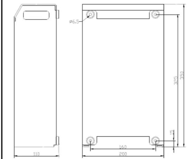
- Connect the housing of the charger to ground. The housing is fitted with an M4 ground screw for this purpose.
- Connect the accompanying temperature sensor to the +T-sense and -T-sense and mount the M8 cable-eye to one of the battery clamps. The connector is located on the front PCB.
- Voltage sense is recommended. Connect 0.75 mm ^2 wires to +V-sense and -V-sense and use a 5 AT fuse near the battery for protection. The connector is located on the front PCB.
- Connect the starter battery (if present) to the Trickle-charge connector located near the minus-output bolt. Use a 25 AT carfuse near the battery for protection.
- If used, the Phoenix Charger Control panel can be connected by means of a standard 8-pole communication cable with 8-pole communication connector. The maximum length is 100m .
- Connect battery cables to the charger. Note that there's only one "minus"- output to connect both battery minus poles. Use a fuse according the table near the battery for protection.
- Connect battery cables to the battery.
- Watch if the POLARITY LED does NOT illuminate.
- If it does reverse battery cables
- Put the car fuses in their sockets
- Connect the AC-in by means of a 3-core cable of 2.5 - 4mm^2 flexible core to the AC-in terminal block. Note that a real PE-connection is strictly necessary.
- Replace the frontplate.
text_image
φ6.5 110 320 350 160 200Phoenix Charger dimensions
flowchart
graph TD
    A["120Vac - 240Vac Mains input"] --> B["DOUBLE POLE SWITCH & CIRCUIT BREAKER"]
    B --> C["BATTERY 2"]
    B --> D["BATTERY 1"]
    B --> E["STARTER BATTERY"]
    C --> F["5AT"]
    D --> G["PHOENIX CHARGER CONTROL"]
    E --> H["Ground"]
    style A fill:#f9f,stroke:#333
    style B fill:#ccf,stroke:#333
    style C fill:#cfc,stroke:#333
    style D fill:#fcc,stroke:#333
    style E fill:#cff,stroke:#333
CONNECTION DIAGRAM PHOENIX CHARGER
Adjustments without remote panel
WARNING: Always check with your battery supplier if the chosen charge characteristic is suitable for your battery and application
- Remove the frontplate and disconnect battery and Voltage sense and Temperature sense and connect a digital voltmeter to – and +1 output.
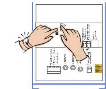
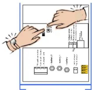
Bulk-current
- While switching on keep both the pushbuttons & pushed.
- Release pushbuttons.
- Bulk LED is flashing alternately with Failure LED.
- Push for up and for down.
- Reading as follows:
Discard first digit of DVM then multiply by 10, i.e:
22.50V => ....2.50 => 25 Amps
15.00V => .....5.00 => 50 Amps
- Switch the charger Off to store.
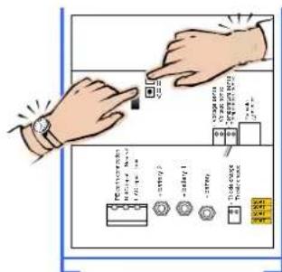
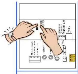
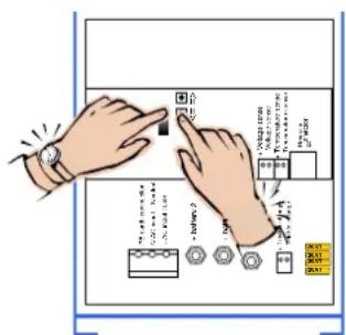
Absorption and Float voltage
- While switching on keep the pushbutton ↑ pushed for Absorption voltage and ↓ for Float-voltage.
- Release pushbuttons.
- Absorption or Float LED is flashing alternately with Failure LED.
- Push for up and for down.
- Reading on voltmeter as is.
- Switch the charger Off to store.
- Please note that in adjust-mode the Temperature sense compensation is not taken into account.
Warning: If the charger is not switched Off after an adjustment the new value will not be stored but will remain on the outputs. After 4 hours the charger continues the normal sequence with the old values. This can be useful if a forced high voltage is wanted to get some life in an assumed 'dead' battery.
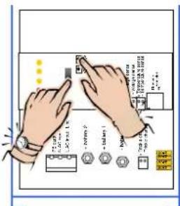
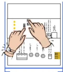
Return to factory settings
- Switch the charger on.
- Keep the pushbutton and/ or pushed while switching off.
• The factory settings are restored.
When ready
- Connect battery and if applicable Voltage sense and Temperature sense.
- Replace the frontplate.
text_image
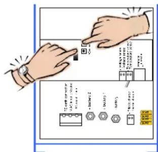
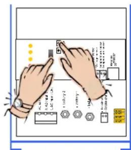
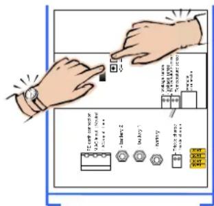
Diagram showing hands interacting with a control panel, labeled with Chinese text and icons for buttons, sensors, and display.Adjusting maximum Bulk current
text_image
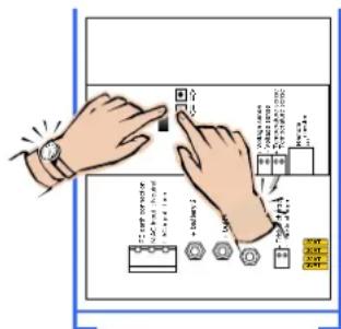
Diagram showing hands interacting with a control panel with labeled buttons and indicatorsAdjusting Absorption voltage
text_image
Diagram showing hands interacting with a control panel and labeled buttons, likely illustrating a process or system interface.Adjusting Float voltage
text_image
Illustration showing hands interacting with a device, labeled with icons and Chinese text indicating functions like 'control', 'train', and 'output'.Restoring defaults
Adjustments with remote panel Phoenix Charger Control
WARNING: Always check with your battery supplier if the chosen charge characteristic is suitable for your battery and application
- Remove the frontplate and connect the Phoenix Charger Control panel to the 8-pin modular jack.
- Disconnect battery, Voltage sense and Temperature sense. A voltmeter is not required but may be useful.
- While switching on keep one of the pushbuttons & pushed.
- Release pushbutton.
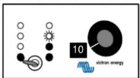
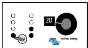
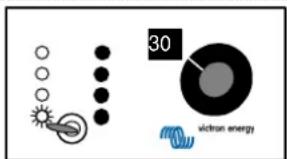
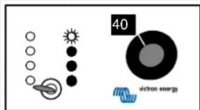
- The adjust knob on the remote panel controls the adjust-mode; the LED's on the charger correspond with the knob as follows:
| knob adjust mode charger LED's | |
| 0% not impl. Failure | |
| 10% Bulk Failure ⇔ Bulk | |
| 20% Absorption Failure ⇔ Absorption | |
| 30% Float Failure ⇔ Float | |
| 40% Rep. Abs. interval Failure ⇔ Abs./Float | |
| 50% Rep. Abs. time Failure ⇔ Bulk/Abs. | |
| 60% Max. Abs. time Failure ⇔ Bulk/Float | |
| 70% Characteristic Failure ⇔ Bulk/Abs./Float | |
| 80% Battery type Failure/Abs. ⇔ Float | |
| 90% not impl. Failure | |
| 100% not impl. Failure | |
- Push for up and for down.
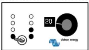
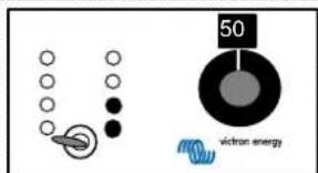
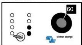
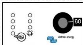
- LED indicators on remote panel read the value as follows:
LED flashing = 1 step
LED on = 2 steps

1 bar flashing = 9 steps
Left bar is [step x10], right bar is [step x1]. To read the Float and Absorption adjustment the lowest value in the table has to be added:
| 12 V models | 24V models | |
| Bulk | 0 – 50 A/30A;step 1A | 0 – 25 A / 16 A; step 1 A |
| Abs | 12.00 – 16.00 V;step 0.1 V | 24.00 – 32.00 V;step 0.1 V |
| Float | 12.00 – 16.00 V;step 0.1 V | 24.00 – 32.00 V;step 0.1 V |
| Rep. Abs. int. 0 – | 45 days; step 1 day ; def = 7 days | |
| Rep. Abs. time | 0 – 72 qu. of an hour; step 1 qu.; def = 4 qu. | |
| Max. Abs. time or Fixed Abs. time | 1 – 8 hrs ; default = 4 hrs. | |
| Characteristic | 1 = Fixed: Fixed Abs. time. default = 4 hrs.Rep. Abs. int. default = 1 dayRep. Abs. time. default = 2 qu.2 = Adaptive3 = Adaptive with BatterySafe mode (default) | |
| Battery type default = 1 | Abs. Voltage | Float Voltage / Reduced Float | Max.Abs. time | ||
| 0: User defined | |||||
| 1: Sonnenschein Dryfit A200 gel | 14.4 V | 28.8 V | 13.8 V/13.0 V | 27.6 V/26.0 V | 4 hrs. |
| 2: Traction (tubular plate) | 15.0 V | 30.0 V | 13.8 V/13.0 V | 27.6 V/26.0 V | 6 hrs. |
| 3: Semitraction ^1 | 14.4 V | 28.8 V | 14.0 V/13.0 V | 28.0 V/26.0 V | 5 hrs. |
| 4: Victory ^1 | 14.8 V | 29.6 V | 14.0 V/13.0 V | 28.0 V/26.0 V | 5 hrs. |
| 12V model | 24V model | 12V model | 24V model | ||
- Turn the knob to another adjust-mode to store or switch Off to escape.
- Switch Off and On to start normal charging sequence.
- Replace the frontplate.
text_image
10 victron energyMax. Bulk current = 25 amps
text_image
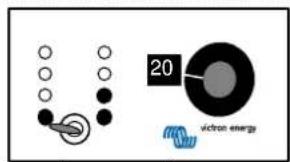
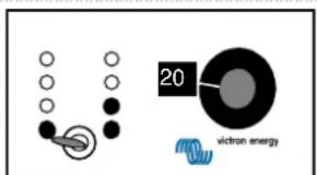
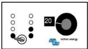
20 vireon energyAbsorption voltage = 12+(1x2)+(2x0.2)= 14.4 volts (12V model) 24+(1x2)+(2x0.2)= 26.4 volts (24V model)
text_image
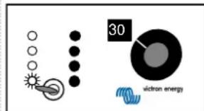
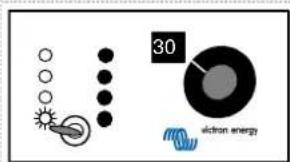
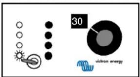
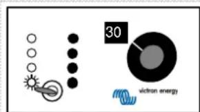
30 victron energyFloat voltage = 12+(1x1)+(4x0.2)=13.8 volts (12V model) 24+(1x1)+(4x0.2)=25.8 volts (24V model)
text_image
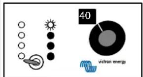
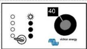
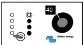
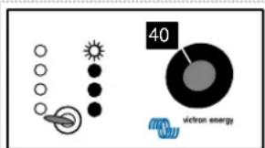
40 victron energyRepeated Absorption interval = 7 days
text_image
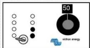
50 victron energyRepeated Absorption time = 4 quarters of an hour
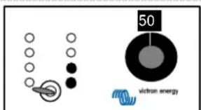
text_image
60 viction energyMaximum Absorption time = 4 hrs.
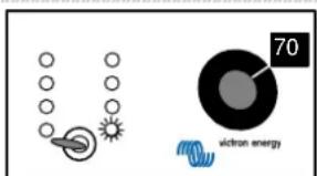
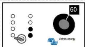
text_image
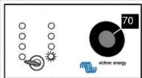
70 victron energyCharacteristic = 1. Fixed mode
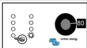
text_image
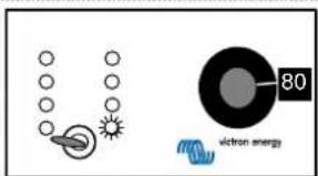
victron energy 80Battery type = 1. Gel
Warning: If the knob is not turned after an adjustment the charger will not store this adjustment. If the Float or Absorption voltage was adjusted and the charger is not switched off this voltage will remain on the outputs.
After 4 hours the charger continues the normal sequence with the old value. This could be useful if a forced high voltage is wanted to get some life in an assumed 'dead' battery.
Return to factory defaults
- Switch the charger on.
- Keep the pushbutton and/ or pushed while switching off.
- The factory defaults are restored.
- Replace the frontplate.
VEILIGHEIDSVOORSCHRIFTEN
Algemene informatie
text_image
Diagram showing hands interacting with a device panel, with Chinese labels and instructional text on the panel.Maximale Bulk stroom instellen
text_image
Diagram showing hands interacting with a control panel with labeled buttons and indicatorsAbsorption spanning instellen
text_image
Diagram showing hands interacting with a device interface with labeled buttons and icons, including Chinese text labels.Float spanning instellen
text_image
Diagram showing hands interacting with a control panel, labeled with Chinese text and icons for buttons, sensors, and function keys.Fabrieksinstellingen terugzetten
text_image
Accu type = 1. Geltext_image
Diagram showing hands operating a control panel with labeled buttons and components, including a timer, magnifying glass, and battery.text_image
Diagram showing hands interacting with a control panel, labeled with Chinese text and icons for buttons, sensors, and meters.text_image
Illustration showing hands interacting with a device, with Chinese text labels and icons indicating functions like 'Close-up', 'Close', and 'Close'.text_image
Diagram showing hands interacting with a device panel, labeled with Chinese text and iconstext_image
10 victor energyCourant maxi. 'Bulk' = 25 ampères
text_image
20 vicon energy22.50V => ....2.50 => 25 A
15.00V => .....5.00 => 50 A
text_image
Diagram showing hands interacting with a control panel, including labeled buttons and a magnified view of the device.text_image
Diagram showing hands interacting with a control panel with labeled buttons and indicatorstext_image
Diagram showing hands interacting with a control panel, labeled with Chinese text and icons for buttons, sensors, and components.text_image
Diagram showing hands interacting with a control panel interface, labeled with Chinese text and iconstext_image
20 victran energyKonstantspannung = 12+(1x2)+(2x0,2)= 14,4 Volt (12V Modelll) 24+(1x2)+(2x0,2)= 26,4 Volt (24V Modelll)
text_image
30 victron energyLadeerhaltungsspannung = 12+(1x1)+(4x0,2)= 13,8 Volt (12V Modell) 24+(1x1)+(4x0,2)= 25,8 Volt (24V Modell)
text_image
40 victron energytext_image
Diagram showing hands interacting with a control panel, labeled with Chinese text and icons for components like battery, switch, and buttons.text_image
Diagram showing two hands interacting with a control panel, labeled with Chinese text and icons for buttons, meters, and sensors.text_image
Diagram showing hands interacting with a control panel, labeled with Chinese text and icons for buttons, sensors, and components.text_image
Diagram showing hands interacting with a control panel, labeled with icons and text in ChineseRipristino parametri predefiniti
text_image
20 uclon energyTensione di assorbimento = 12+(1x2)+(2x0.2)= 14.4 volt (modello 12V) 24+(1x2)+(2x0.2)= 26.4 volt (modello 24V)
text_image
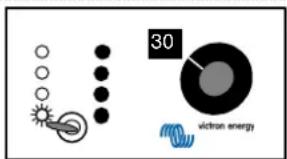
30 victron energyTensione fluttuante = 12+(1x1)+(4x0.2)= 13.8 volt (modello 12V) 24+(1x1)+(4x0.2)= 25.8 volt (modello 24V)
text_image
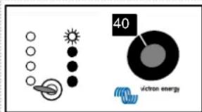
40 victron energytext_image
victran energy 70text_image
Illustration showing hands interacting with a device, labeled with icons and Chinese text indicating components or functions.Justering, maksimal Bulk strøm

text_image
Diagram illustrating a process with labeled steps and icons, showing hand positioning and action buttons.text_image
Illustration showing hands interacting with a control panel with labeled buttons and iconstext_image
Diagram showing hands interacting with a control panel with labeled buttons and indicatorstext_image
Diagram illustrating solar radiation, electron emission, and electron energy with labeled componentsMax. Bulk strøm
= 25 amp
text_image
20 victor energyAbsorptions-spænding =
12+(1x2)+(2x0.2)=14.4 volt (12V model)
24+(1x2)+(2x0.2)=26.4 volt (24V model)
text_image
30 electron energyFloat-spænding =
12+(1x1)+(4x0.2)=13.8 volt (12V model)
24+(1×1)+(4×0.2)=25.8 volt (24V model)
text_image
40 victron energyRepeteret Absorptionsinterval
= 7 dage
text_image
50 viction energyRepeteret Absorptionstid
= 4 kvarter

text_image
60 electron energyMaximum Absorptionstid
= 4 timer
text_image
70 victron energyKarakteristik
= 1. Fast indst.
text_image
80 victron energyBatteritype
= 1. Gel
text_image
Diagram showing hands interacting with a control panel, labeled with Chinese text and icons for buttons, sensors, and components.text_image
Diagram showing hands interacting with a control panel with labeled buttons and indicatorstext_image
Diagram showing hands interacting with a control panel, labeled with Chinese text and icons for buttons, sensors, and buttons.text_image
Diagram showing hands interacting with a device panel, labeled with Chinese text and iconstext_image
40 viction energytext_image
60 viction energyKOBLINGSDIAGRAM PHOENIX-LADER
22.50V => ....2.50 => 25 Amp
15.00V => .....5.00 => 50 Amp
text_image
Diagram showing hands interacting with a control panel, labeled with Chinese text and icons for buttons, sensors, and indicators.Justere maks Bulk-strøm
text_image
Diagram illustrating hand positioning and adjustment of a device with labeled components and buttonsJustere Absorbering-spenning
text_image
Illustration showing hands interacting with a device, with Chinese labels and icons indicating functions like '合' (合一) and '操作按钮'.Justere Flyt-spenning
text_image
Diagram showing hands interacting with a control panel, labeled with Chinese text and icons for buttons, meters, and indicators.Gjenopprette standardinnstillinger
Justeringer med fjernpanelet Phoenix-laderkontroll
Maks. Bulk-strøm
= 25 amp

text_image
20 ictron energyAbsorbering-spenning =
12+(1x2)+(2x0,2)=14,4 volt (12V modell)
24+(1x2)+(2x0,2)=26,4 volt (24V modell)
text_image
30 victron energyFlyt-spenning =
12+(1x1)+(4x0,2)=13,8 volt (12V modell)
24 + (1 × 1) + (4 × 0, 2) = 25,8 volt (24V modell)
text_image
40 electron energytext_image
Diagram showing hands interacting with a control panel, labeled with Chinese text and icons for buttons, sensors, and contacts.text_image
Diagram showing hands interacting with a control panel with labeled buttons and indicatorstext_image
Illustration showing hands interacting with a device, labeled with Chinese text and icons for buttons, sensors, and components.text_image
Diagram showing hands interacting with a control panel, labeled with technical specifications and buttonstext_image
10 victor energyCorrente máx. de carga = 25 amperes
text_image
20 victron energytext_image
30 victor energytext_image
Diagram showing hands operating a control panel with labeled buttons and indicators, including 'Control Panel' and 'Control Bracket'.text_image
Diagram showing hands interacting with a control panel, labeled with buttons and icons for voltage, current, and power.text_image
Illustration showing hands interacting with a control panel, with Chinese text labels and icons on the screen.text_image
Illustration showing hands interacting with a control panel, labeled with Chinese text and icons for buttons, sensors, and display.text_image
viction energy 10text_image
20 viction energyTensión de carga rápida = 12+(1x2)+(2x0,2)= 14,4 voltios (modelo de 12V) 24+(1x2)+(2x0,2)= 26,4 voltios (modelo de 24V)
text_image
30 victron energyTensión de carga flotante = 12+(1x1)+(4x0,2)= 13,8 voltios (modelo de 12V) 24+(1x1)+(4x0,2)= 25,8 voltios (modelo de 24V)
text_image
40 victron energytext_image
Diagram showing hands interacting with a control panel, with Chinese text labels and icons indicating components like battery, switch, and buttons.Justering av max. bulkström
text_image
Diagram illustrating a hand interacting with a device, showing labeled components and directional arrows.text_image
Diagram showing hands interacting with a control panel, labeled with icons and text in Chinesetext_image
Illustration showing hands interacting with a control panel with labeled buttons and indicatorstext_image
10 vichron energyMax. bulkström = 25 ampere
text_image
20 silicon energyAbsorptionspänning = 12+(1x2)+(2x0,2)= 14,4 volt (12V-modell) 24+(1x2)+(2x0,2)= 26,4 volt (24V-modell)

text_image
30 electron energyFrispänning = 12+(1x1)+(4x0,2)= 13,8 volt (12V-modell) 24+(1x1)+(4x0,2)= 25,8 volt (24V-modell)

text_image
40 electron energyUpprepad absorptionsintervall = 7 dagar
text_image
50 victran energyUpprepad absorptionstid = 4 kvart
text_image
60 electron energyMax. absorptionstid = 4 timmar

text_image
70 victron energyKurva = 1. Fast
text_image
80 silicon energyBatterityp = 1. Gel
| Model 12/50 12/30 24/25 24/16 | ||||
| Nominal input voltage range 120 - 240 Vac | ||||
| Absolute minimum working voltage | 90 Vac | |||
| Absolute maximum working voltage | 265 Vac | |||
| Frequency range | 45 - 65 Hz | |||
| Maximum input current | 4A/230 Vac | |||
| 10A/120 Vac | ||||
| Powerfactor (cos φ) | ≈1 | |||
| Input fuse | 15 AT 6.3 x 32 mm | |||
| Absorption charge voltage default | 14,4 Vdc | 28,8 Vdc | ||
| Float charge voltage default | 13,8 Vdc | 27,6 Vdc | ||
| Adjustment range | 12 - 16 Vdc | 24 - 32 Vdc | ||
| Bulk charge current shared between output +1 and output +2 | 50 Adc | 30 Adc | 25 Adc | 16 Adc |
| @ Vin=230Vac/Vout=12Vdc/Ta=25°C | @ Vin=230Vac/Vout=24Vdc/Ta=25°C | |||
| Short circuit current | 50 Adc | 30Adc | 25 Adc | 16 Adc |
| Adjustment range | 1 - 50 Adc | 1 - 30 Adc | 1 - 25 Adc | 1 - 16 Adc |
| Maximum trickle charge current | 4 Adc | 4 Adc | ||
| Current/voltage stability | ±1% | |||
| Output fuse | 4x 20 A carfuse | 2x 20 A carfuse | ||
| Battery leakage current when charger is switched off | <2 mA | |||
| Recommended battery capacity | 200 - 400 Ah | 100 - 200 Ah | 100 - 200 Ah | 45 - 100 Ah |
| Environment | ||||
| EMC | EEC 89/336 | |||
| Emission | EN55014 (1993) | |||
| EN61000-3-2 | ||||
| EN61000-3-3 | ||||
| Immunity | EN55104 (1995) | |||
| Safety | EN60335-2-29 (1991) | |||
| Vibration | IEC68-2-6 : 10 - 150 Hz / 1.0 G | |||
| Shock | IEC68-2-29: 1000 times XYZ +/- 10 G / 16 ms | |||
| Operating temperature | 0-40°C | |||
| Transport & storage temperature | -20 - +60°C | |||
| Relative humidity | max. 95% non condensing | |||
| Noise | < 45 dB (A) | |||
| Ventilation | Combined convection / forced-air | |||
| Connections | ||||
| Mains connector | connection block provision for 4 mm2 | |||
| Output +1/+2 battery connection | M6 bolts | |||
| Trickle charge connection connection block provision for 1.5 mm2 | ||||
| Earthing | M4 screw | |||
| Temperature sensor | connection block provision for 1.5 mm2 | |||
| Voltage sense | connection block provision for 1.5 mm2 | |||
| Remote panel / RS485 | RJ45 connector | |||
| Mechanical | ||||
| Cabinet | Aluminium IP21, RAL5012 (blue) epoxy coated | |||
| Size (h x w x d) | 350 x 200 x 110 (mm) | |||
| Weight | 3.8 kg | |||
| Weight including box | 4.9 kg | |||
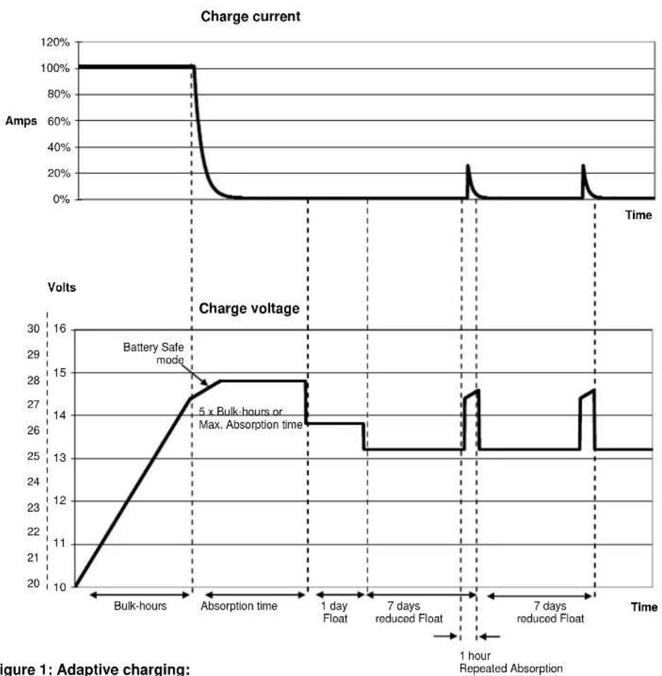
Figure 1: Adaptive charging:
Bulk-mode: Entered after a reset or if the battery voltage becomes 1.3V resp. 2.6V (for 12V and 24V charger) lower than Float voltage. Constant current is applied until the battery has reached 14.4V resp. 28.8V (for 12V and 24V charger, temperature compensated).
Battery Safe mode: The applied voltage to the battery is raised gradually until the set Absorption voltage is reached. The Battery Safe Mode is part of the calculated absorption time.
Absorption-mode: Absorption voltage is applied until {actual-Bulk-Ah*5 / max.adjusted-Bulk-current} (in hours) is reached. Usually {actual-Bulk-Ah*5} = {max.adjusted-Bulk-current * Bulk-hours *5}, but the actual-Bulk-current can be limited by ambient temperature, or remote-control. The maximum time in Absorption mode is the Maximum Absorption time set with control panel.
Float-mode: Float voltage is applied to keep the battery fully charged and to protect it against self discharge. After one day of Float charge a reduced Float charge is applied. This is 13V resp. 26V (for 12V and 24V charger, temperature compensated). This will limit water loss to a minimum when the battery is stored for the winter season.
After an adjustable time (default = 7 days) the charger will enter Repeated Absorption-mode for an adjustable time (default = 4 quarters).
other
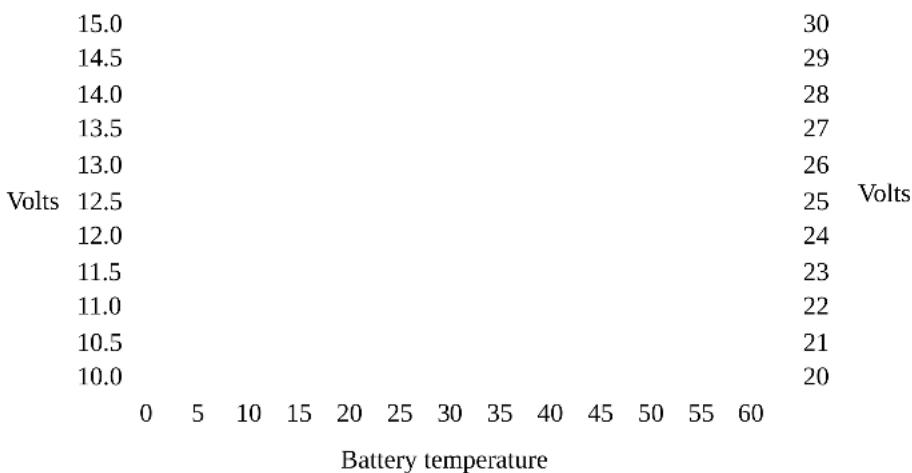
| Voltage | Value | |---|---| | 15.0 | 30 | | 14.5 | 29 | | 14.0 | 28 | | 13.5 | 27 | | 13.0 | 26 | | Volts 12.5 | 25 | | 12.0 | 24 | | 11.5 | 23 | | 11.0 | 22 | | 10.5 | 21 | | 10.0 | 20 | | Battery temperature | 0 5 10 15 20 25 30 35 40 45 50 55 60 |Figure 2: Temperature compensation
Default output voltages for Float and Absorption are at 20°C. In adjust mode temperature compensation does not apply.
line
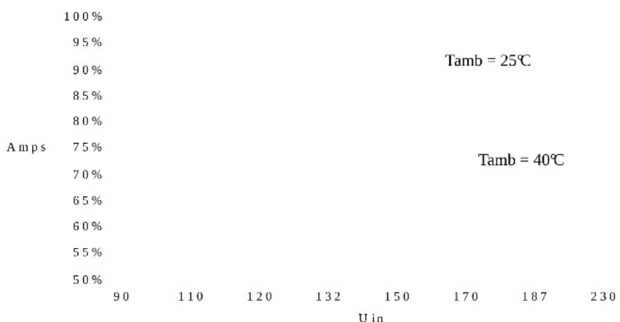
| Amps | 100% (%) | 95% (%) | 90% (%) | 85% (%) | 80% (%) | |---|---|---|---|---|---| | 75% | | | | | | | 70% | | | | | | | 65% | | | | | | | 60% | | | | | | | 55% | | | | | | | 50% | | | | | | | 90 | | 110 | 120 | 132 | 150 | | 170 | | | | | | | 187 | | | | | | | 230 | | | | | | Tamb = 25℃ Tamb = 40℃ U inFigure 3: Maximum output current vs. input voltage:
Output voltage = 12.0V / 24.0V
Default factory settings:
Repeated Absorption interval 7 days
Repeated Absorption time 4 quarters of an hour
Maximum Absorption time 4 hrs
Characteristic: Default = 3 1 = Fixed
Absorption time 4 hrs
Repeated Absorption interval 1 day
Repeated Absorption time 2 quarters
2 = Adaptive
3 = Adaptive with
Battery Safe Mode
| Battery type: Default = 1 Abs. Voltage Float Voltage / Reduced Float | Max.Abs.time | ||||
| 0:User defined | |||||
| 1: Sonnenschein Dryfit A200 Gel | 14.4 V | 28.8 V | 13.8 V / 13.0V | 27.6 V / 26.0V | 4 hrs |
| 2: Traction (Tubular plate) | 15.0 V | 30.0 V | 13.8 V / 13.0V | 27.6 V / 26.0V | 6 hrs |
| 3: Semitraction | 14.4 V | 28.8 V | 14.0 V / 13.0V | 28.0 V / 26.0V | 5 hrs |
| 4: Victory | 14.8 V | 29.6 V | 14.0 V / 13.0V | 28.0 V / 26.0V | 5 hrs |
| 12V | 24V | 12V | 24V | ||
| model | model | model | model | ||
Factory defaults can always be restored by your authorized Victron Energy dealer. Acting sequence is described in the installation part of the manual.
Serialnumber:
Dealer:
Victron Energy B.V.
The Netherlands
Phone : ** 31 36 535 97 00
Customer support desk : ** 31 36 535 97 77
E-mail : sales@victronenergy.com
Internet site : http://www.victronenergy.com
Article Number : ISM010001000
Revision : rev02
Date : 04-10-2010