
EasySolar - Battery charger VICTRON ENERGY - Free user manual and instructions
Find the device manual for free EasySolar VICTRON ENERGY in PDF.

| Product type | All-in-one solar battery charger with MPPT controller, inverter/charger and AC distribution |
| Brand | Victron Energy |
| Model | EasySolar (12/1600/70 or 24/1600/40) |
| Dimensions (H x W x D) | 745 x 214 x 110 mm |
| Weight | 11.7 kg |
| AC input voltage | 187-265 VAC |
| Battery voltage | 12 V or 24 V (depending on model) |
| Maximum battery charge current | 70 A (12 V model) / 40 A (24 V model) |
| Continuous output power | 1600 VA / 1300 W at 25°C |
| Peak power | 3000 W |
| Maximum PV power | 700 W (12 V) / 1400 W (24 V) |
| Maximum PV open circuit voltage | 100 V |
| Maximum efficiency (inverter) | 92% (12 V) / 94% (24 V) |
| Maximum efficiency (MPPT) | 98% |
| Main features | PowerAssist, PowerControl, adaptive 4-stage charging, standby mode, temperature compensation, programmable relay |
| Protection rating | IP21 |
| Operating temperature range | -20 to +50 °C |
| Maximum humidity (non-condensing) | 95% |
| Maintenance and cleaning | No special maintenance required; check connections once a year; avoid moisture, oil and dust |
| Safety | Safety class I, protection against short circuit, overload, overtemperature, PV reverse polarity, battery ripple |
| Spare parts and repairability | No user-serviceable parts; contact a qualified technician for any repairs |
Frequently Asked Questions - EasySolar VICTRON ENERGY
User questions about EasySolar VICTRON ENERGY
0 question about this device. Answer the ones you know or ask your own.
Ask a new question about this device
Download the instructions for your Battery charger in PDF format for free! Find your manual EasySolar - VICTRON ENERGY and take your electronic device back in hand. On this page are published all the documents necessary for the use of your device. EasySolar by VICTRON ENERGY.
USER MANUAL EasySolar VICTRON ENERGY
1. SAFETY INSTRUCTIONS
General
Please familiarize yourself with the safety features and instructions by first reading the documentation supplied with this product before using the equipment. This product has been designed and tested in accordance with international standards. The equipment must be used exclusively for the purpose for which it was designed.
WARNING: ELECTRIC SHOCK HAZARD.
The product is used in conjunction with a permanent energy source (battery). Input and/or output terminals may still be dangerously energized, even when the equipment is switched off. Always switch off the AC supply and the battery before carrying out maintenance or servicing the product.
The product has no internal user-serviceable components. Do not remove the front plate or operate the product if any panels have been removed. All servicing must be undertaken by qualified personnel.
Never use the product where there is a risk of gas or dust explosions. Consult the battery manufacturer's information to ascertain that the product is intended for use in conjunction with the battery. Always comply with the battery manufacturer's safety instructions.
WARNING: Do not lift heavy loads without assistance.
Installation
Read the installation instructions in the installation manual before installing the equipment.
This is a Safety Class I product (supplied with a protective grounding terminal). Uninterruptible protective grounding must be provided at the AC input and/or output terminals. Alternatively the grounding point located externally on the product may be used. Whenever it is likely that the grounding protection has been damaged, the product must be turned off and secured against unintended operation; please contact qualified service staff.
Ensure that the DC and AC input cables are fused and fitted with circuit breakers. Never replace a safety component with a different type. Consult the manual to determine the correct component.
Before applying power, ensure that the available power source matches the configuration settings of the product as described in the manual.
Ensure that the equipment is used under the correct ambient conditions. Never operate the product in a wet or dusty environment. Ensure there is adequate free space for ventilation around the product and check that the ventilation vents are not blocked.
Ensure that the required system voltage does not exceed the product's capacity.
Transport and Storage
Ensure that the mains power and battery cables have been disconnected before storing or transporting the product.
No liability can be accepted for any transport damage if the equipment is shipped in non-original packaging.
Store the product in a dry environment; the storage temperature must be between -40 °C and 60 °C.
Consult the battery manufacturer's manual in respect of transport, storage, charging, recharging and disposal of the battery.
2. DESCRIPTION
2.1 General
All-in-one solar power solution
The EasySolar combines a MPPT solar charge controller, an inverter/charger and AC distribution in one enclosure.
The product is easy to install, with a minimum of wiring.
Solar charge controller: SmartSolar MPPT 100/50
Up to three strings of PV panels can be connected with three sets of MC4 (PV-ST01) PV connectors.
Inverter/charger: MultiPlus Compact 12/1600/70 or 24/1600/40
The MPPT charge controller and the MultiPlus inverter/charger share the DC battery cables (included). The batteries can be charged with solar power (MPPT) and/or with AC power (inverter/charger) from the utility grid or a genset.
AC distribution
The AC distribution consists of a RCD (30 mA/16 A) and four AC outputs protected by two 10 A and two 16 A circuit breakers.
One 16 A output is controlled by the AC input: it will switch on only when AC is available.
PowerAssist
Unique PowerAssist technology protects the utility or generator supply from being overloaded by adding extra inverter power when needed.
2.2 Inverter
MultiPlus Compact-functional
The MultiPlus Compact gets its name from the multiple functions it can perform. It is a powerful true sine wave inverter, a sophisticated battery charger that features adaptive charge technology and a high-speed AC transfer switch in a single compact enclosure. Beside these primary functions, however, the MultiPlus Compact has several advanced features that provide a range of new applications as outlined below.
Uninterrupted AC power
In the event of a grid failure, or shore or generator power being disconnected, the inverter within the MultiPlus Compact is automatically activated and takes over supply to the connected loads. This happens so fast (less than 20 milliseconds) that computers and other electronic equipment will continue to operate without disruption.
PowerControl – Dealing with limited generator or shore side power
With a Multi Control Panel a maximum generator or shore current can be set. The MultiPlus Compact will then take account of other AC loads and use whatever is extra for charging, thus preventing the generator or shore supply from being overloaded.
PowerAssist – Boosting the capacity of shore or generator power
This feature takes the principle of PowerControl to a further dimension allowing the MultiPlus Compact to supplement the capacity of the alternative source. Where peak power is so often required only for a limited period, it is possible to reduce the size of generator needed or conversely enable more to be achieved from the typically limited shore connection. When the load reduces, the spare power is used to recharge the battery.
Programmable relay
The MultiPlus is equipped with a programmable relay that by default is set as an alarm relay. The relay can be programmed for all kinds of other applications however, for example as a starter relay for a generator.
2.3 Battery Charger
Adaptive 4-stage charge characteristic: bulk – absorption – float – storage
The MultiPlus Compact features a microprocessor controlled ‘adaptive’ battery management system that can be preset to suit different types of batteries. The ‘adaptive’ feature will automatically optimize the process relative to the way the battery is being used.
The right amount of charge: variable absorption time
When only shallow discharges occur (a yacht connected to shore power for example) the absorption time is kept short in order to prevent overcharging of the battery. After a deep discharge the absorption time is automatically increased to make sure that the battery is completely recharged.
Preventing damage due to excessive gassing: the BatterySafe mode
If, in order to quickly charge a battery, a high charge current in combination with a high absorption voltage has been chosen, the MultiPlus Compact will prevent damage due to excessive gassing by automatically limiting the rate of voltage increase once the gassing voltage has been reached.
Less maintenance and aging when the battery is not in use: the Storage mode
The storage mode kicks in whenever the battery has not been subjected to discharge during 24 hours. In the storage mode float voltage is reduced to 2.2 V/cell (13.2 V for a 12 V battery) to minimize gassing and corrosion of the positive plates. Once a week the voltage is raised back to the absorption level to ‘equalize’ the battery. This feature prevents stratification of the electrolyte and sulphation, a major cause of early battery failure.
To increase battery life: temperature compensation
Every MultiPlus Compact comes with a battery temperature sensor. When connected, charge voltage will automatically decrease with increasing battery temperature. This feature is especially recommended for sealed batteries and/or when important fluctuations of battery temperature are expected.
Learn more about batteries and battery charging
To learn more about batteries and charging batteries, please refer to our book ‘Electricity on Board’ (available free of charge from Victron Energy and downloadable from www.victronenergy.com). For more information about adaptive charging please look under Technical Briefs on our website.
2.4 Charge Controller MPPT 100/50
Charge current up to 50 A and PV voltage up to 100 V
The SmartSolar MPPT 100/50 charge controller is able to charge a lower nominal-voltage battery from a higher nominal voltage PV array.
Ultra-fast Maximum Power Point Tracking (MPPT)
Especially in case of a clouded sky, when light intensity is changing continuously, an ultra fast MPPT controller will improve energy harvest by up to 30 % compared to PWM charge controllers and by up to 10 % compared to slower MPPT controllers.
Advanced Maximum Power Point Detection in case of partial shading conditions
If partial shading occurs, two or more maximum power points may be present on the power-voltage curve.
Conventional MPPTs tend to lock to a local MPP, which may not be the optimum MPP.
The innovative SmartSolar algorithm will always maximize energy harvest by locking to the optimum MPP.
Outstanding conversion efficiency
No cooling fan. Maximum efficiency exceeds 98 %. Full output current up to 40 °C (104 °F).
Flexible charge algorithm
Eight preprogrammed algorithms, selectable with a rotary switch.
Extensive electronic protection
Over-temperature protection and power derating when temperature is high.
PV short circuit and PV reverse polarity protection.
PV reverse current protection.
Internal temperature sensor
Compensates absorption and float charge voltages for temperature.
Adaptive three step charging
The SmartSolar MPPT Charge Controller is configured for a three-step charging process: Bulk – Absorption – Float.
Bulk stage
During this stage the controller delivers as much charge current as possible to rapidly recharge the batteries.
Absorption stage
When the battery voltage reaches the absorption voltage setting, the controller switches to constant voltage mode.
When only shallow discharges occur the absorption time is kept short in order to prevent overcharging of the battery. After a deep discharge the absorption time is automatically increased to make sure that the battery is completely recharged. Additionally, the absorption period is also ended when the charge current decreases to less than 2 A.
Float stage
During this stage, float voltage is applied to the battery to maintain it in a fully charged state.
2.5 Configuration Assistants
Several software programs (Assistants) are available to configure the system for various grid interactive or stand alone applications. Please see http://www.victronenergy.nl/support-and-downloads/software/
3. OPERATION – inverter/charger
3.1 On/Off/Charger Only Switch
When switched to 'on', the product is fully functional. The inverter will come into operation and the LED 'inverter on' will light up.
An AC voltage connected to the 'AC in' terminal will be switched through to the 'AC out' terminal, if within specifications. The inverter will switch off, the 'mains on' LED will light up and the charger commences charging. The 'bulk', 'absorption' or 'float' LEDs will light up, depending on the charger mode.
If the voltage at the 'AC-in' terminal is not within specifications, the inverter will switch on. When the switch is switched to 'charger only', only the battery charger of the MultiPlus will operate (if mains voltage is present). In this mode input voltage also is switched through to the 'AC out' terminal.
NOTE: When only the charger function is required, ensure that the switch is switched to 'charger only'. This prevents the inverter from being switched on if the mains voltage is lost, thus preventing your batteries from running flat.
3.2 Remote control
Remote control is possible with a 3-way switch or with a Digital Multi Control panel.
The Control panel has a simple rotary knob with which the maximum current of the AC input can be set: see PowerControl and PowerAssist in Section 2.
For the appropriate DIP switch settings, see sect. 5.5.1.
3.3 Equalisation and forced absorption
3.3.1 Equalisation
Traction batteries may require regular equalisation charging. In the equalisation mode, the MultiPlus will charge with increased voltage for one hour (1 V above the absorption voltage for a 12 V battery, 2 V for a 24 V battery). The charging current is then limited to 1/4 of the set value. The 'bulk' and 'absorption' LEDs flash intermittently.

Equalisation mode supplies a higher charging voltage than most DC consuming devices can cope with. These devices must be disconnected before additional charging takes place.
3.3.2 Forced absorption
Under certain circumstances, it can be desirable to charge the battery for a fixed time at absorption voltage level. In Forced Absorption mode, the MultiPlus will charge at the normal absorption voltage level during the set maximum absorption time. The ‘absorption’ LED will be ‘on’.
3.3.3 Activating equalisation or forced absorption
The MultiPlus can be put into both these states from the remote panel as well as with the front panel switch, provided that all switches (front, remote and panel) are set to 'on' and no switches are set to 'charger only'.
In order to put the MultiPlus in this state, the procedure below should be followed.
If the switch is not in the required position after following this procedure, it can be switched over quickly once. This will not change the charging state.
NOTE: Switching from 'on' to 'charger only' and vice versa, as described below, must be done quickly. The switch must be toggled such that the intermediate position is 'skipped', as it were. If the switch remains in the 'off' position even for a short time, the device may be turned off. In that case, the procedure must be restarted at step 1. A certain degree of familiarisation is required when using the front switch on the Compact in particular. When using the remote panel, this is less critical.
Procedure:
- Check whether all switches (i.e. front switch, remote switch or remote panel switch if present) are in the 'on' position.
- Activating equalisation or forced absorption is only meaningful if the normal charging cycle is completed (charger is in 'Float').
- To activate:
a. Switch rapidly from 'on' to 'charger only' and leave the switch in this position for 12 to 2 seconds.
b. Switch rapidly back from 'charger only' to 'on' and leave the switch in this position for 12 to 2 seconds.
c. Switch once more rapidly from 'on' to 'charger only' and leave the switch in this position. - On the MultiPlus the three LEDs 'Inverter', 'Charger' and 'Alarm' will now flash 5 times.
If a MultiControl panel is connected, on the panel the LEDs 'bulk', 'absorption' and 'float' will also flash 5 times. - Subsequently, on the MultiPlus the LEDs 'Bulk', 'Absorption' and 'Float' will each light during 2 seconds. If a MultiControl panel is connected, on the panel the LEDs 'bulk', 'absorption' and 'float' will also each light during 2 seconds.
6.
a. If the switch on the MultiPlus is set to 'on' while the 'Bulk' LED lights, the charger will switch to equalisation. Similarly, if the switch on the MultiControl panel is set to 'on' while the 'Bulk' LED lights, the charger will switch to equalisation.
b. If the switch on the MultiPlus is set to 'on' while the 'Absorption' LED lights, the charger will switch to forced absorption.
Similarly, if the switch on the MultiControl panel is set to 'on' while the 'Absorption' LED lights, the charger will switch to forced absorption.
c. If the switch on the MultiPlus is set to 'on' after the three LED sequence has finished, the charger will switch to 'Float'.
Similarly, if the switch on the MultiControl panel is set to 'on' after the three LED sequence has finished, the charger will switch to 'float'.
d. If the switch is has not been moved, the MultiPlus will remain in 'charger only' mode and switch to 'Float'.
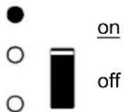
3.4 LED Indications

LED off
LED flashes
LED illuminated
Inverter
inverter
charger
alarm
charger only
The inverter is switched on and supplies power to the load. Battery operation.
inverter
charger
alarm
charger only
The inverter is switched on and supplies power to the load.
Pre alarm: overload, or battery voltage low, or inverter temperature high
inverter
charger
alarm
charger only
The inverter is switched off.
Alarm: overload, or battery voltage low, or inverter temperature high, or DC ripple voltage on battery terminal was too high.
Charger
inverter
charger
alarm


charger only
The AC input voltage is switched through and the charger operates in bulk or absorption mode.
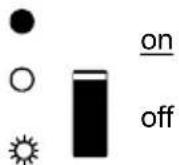
inverter
charger
alarm


off
charger only
The AC input voltage is switched through and the charger is switched off. The battery charger can not reach battery end voltage (bulk protection mode).
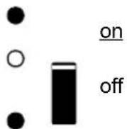
inverter
charger
alarm


on
off
charger only
The AC input voltage is switched through and the charger operates in bulk or absorption mode.
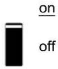
inverter
charger
alarm


on
off
charger only
The AC input voltage is switched through and the charger operates in float mode.
4. INSTALLATION – inverter/charger

This product should be installed by a qualified electrician.
4.1 Location
The product must be installed in a dry and well-ventilated area, as close as possible to the batteries. There should be a clear space of at least 10 cm around the appliance for cooling.

Excessively high ambient temperature will result in the following:
Reduced service life.
Reduced charging current.
Reduced peak capacity or shutdown of the inverter.
Never mount the appliance directly above the batteries.
The product is suitable for wall mounting. For mounting see appendix A.
The appliance can be mounted horizontally as well as vertically; vertical mounting is preferable.
The vertical position offers optimum cooling.

The interior of the product must remain accessible after installation.
Try and keep the distance between the product and the battery to a minimum in order to minimize cable voltage losses.

For safety purposes, this product should be installed in a heat-resistant environment if it is used with equipment where a substantial amount of power is to be converted. You should prevent the presence of e.g. chemicals, synthetic components, curtains or other textiles, etc., in the immediate vicinity.
4.2 Connection of Battery cables (see appendix A)
In order to fully utilize the full capacity of the product, batteries with sufficient capacity and battery cables with sufficient cross section should be used. See table.
| 24/1600 | 12/1600 | |
| Preassembled cable length 1.5 m (mm ^2 ) | 25 35 | |
| Recommended cross section (mm ^2 ) | ||
| 1.5 ^1 → 5 m | 35 | 70 |
| 5 → 10 m | 70 | 140 |
Procedure
Proceed as follows to connect the battery cables:

Use an insulated box spanner in order to avoid shorting the battery. Avoid shorting the battery cables.
Connect the battery cables: the + (red) and the - (black), to the battery see appendix A.
Reverse polarity connection (+ to - and - to +) will cause damage to the product. (Safety fuse inside the EasySolar chassis can be damaged)
Secure the nuts tightly in order to reduce the contact resistance as much as possible.
4.3 Connection of the AC cabling
This is a Safety Class I product (supplied with a protective grounding terminal). Uninterruptible protective grounding must be provided at the AC input and/or output terminals and/or chassis grounding point located externally on the product.

The EasySolar is provided with a ground relay (relay H, see appendix B) that automatically connects the Neutral output to the chassis if no external AC supply is available. If an external AC supply is provided, the ground relay H will open before the input safety relay closes. This ensures the correct operation of an earth leakage circuit breaker that is connected to the output.
- In a fixed installation, an uninterruptable grounding can be secured by means of the grounding wire of the AC input. Otherwise, the casing must be grounded.
- In a mobile installation (for example, with a shore current plug), interrupting the shore connection will simultaneously disconnect the grounding connection. In that case, the casing must be connected to the chassis (of the vehicle) or to the hull or grounding plate (of the boat).
- In case of a boat, direct connection to the shore ground is not recommended because of potential galvanic corrosion. The solution to this is using an isolation transformer.
The mains input & output terminal connector can be found on the bottom of the MultiPlus Compact, see appendix A. The shore or mains cable must be connected to the connector with a three-wire cable. Use a three-wire cable with a flexible core and a cross section of 2.5 mm^2 .
Procedure
Proceed as follows to connect the AC cables:
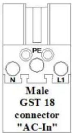
The AC output cable can be connected directly to the male-connector (the connector pulls out!).
The terminal points are indicated clearly. From left to right: 'N' (neutral), earth, and 'L1' (phase).
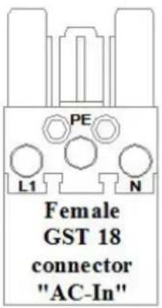
The AC input cable can be connected directly to the female-connector (the connector pulls out!).
The terminal points are indicated clearly. From left to right: 'L1' (phase), earth, and 'N' (neutral).
Push the 'input' connector into the AC-in connector (left-side).
Push the 'output' connectors into the AC-out connector (AC0 to AC3 from left to right-side).
4.4 Optional Connections
A number of optional connections are possible:
Undo the four screws at the front of the enclosure and remove the front panel.
4.4.1 Second Battery
The MultiPlus Compact has a connection (+) for charging a starter battery. For connection see appendix 1.
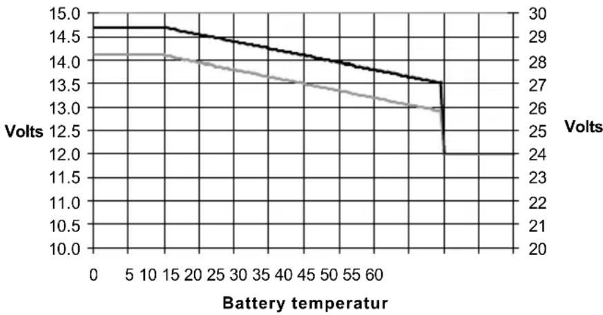
4.4.2 Temperature Sensor
The temperature sensor supplied with the product may be used for temperature-compensated charging. The sensor is insulated and must be mounted on the batteries minus pole. Default output voltages for Float and Absorption are at 25 °C. In adjust mode temperature compensation is disabled.
line
| Battery temperature | Volts | | ------------------- | ----- | | 0 | 14.7 | | 5 | 14.6 | | 10 | 14.5 | | 15 | 14.4 | | 20 | 14.3 | | 25 | 14.2 | | 30 | 14.1 | | 35 | 14.0 | | 40 | 13.9 | | 45 | 13.8 | | 50 | 13.7 | | 55 | 13.6 | | 60 | 13.5 | | 65 | 13.4 | | 70 | 13.3 | | 75 | 13.2 | | 80 | 13.1 | | 85 | 13.0 | | 90 | 12.9 | | 95 | 12.8 | | 100 | 12.7 |4.4.3 Remote Control panel & remote on/off switch
The product can be remotely controlled in two ways:
- With an external 3-way switch
- With a Multi Control Panel
Please see section 5.5.1. for appropriate DIP switch settings.
Only one remote control can be connected, i.e. either a switch or a remote control panel.
4.4.4. Programmable relay
The MultiPlus is equipped with a multi-functional relay that by default is programmed as an alarm relay. However, the relay can be programmed for all kinds of other applications, for example to start a generator (VEConfigure software needed).
Near the connection terminals an LED illuminates when the relay is activated (refer to S, see appendix A)
5. CONFIGURATION – inverter/charger

Settings may only be changed by a qualified engineer
Carefully read the instructions before changes are made.
Batteries should be placed in a dry and well-ventilated area during charging.
5.1 Standard settings: ready for use
On delivery, the MultiPlus is set to standard factory values. In general, these settings are suitable for single-unit operation.
Warning: Possibly, the standard battery charging voltage is not suitable for your batteries! Refer to the manufacturer's documentation, or to your battery supplier!
Standard MultiPlus factory settings
| Inverter frequency 50 Hz | |
| Input frequency range | 45 - 65 Hz |
| Input voltage range | 180 - 265 VAC |
| Inverter voltage 230 VAC | |
| Stand-alone / parallel / 3-phase | stand-alone |
| Search mode off | |
| Ground relay on | |
| Charger on/off on | |
| Battery charge curve | four-stage adaptive with BatterySafe mode |
| Charge current | 75 % of the maximum charge currentVictron Gel Deep Discharge (also suitable for Victron AGM Deep Discharge) |
| Automatic equalisation charging | off |
| Absorption voltage | 14.4 / 28.8 V |
| Absorption time | up to 8 hours (depending on bulk time) |
| Float voltage | 13.8 / 27.6 V |
| Storage voltage | 13.2 / 26.4 V (not adjustable) |
| Repeated absorption time 1 hour | |
| Absorption repeat interval | 7 days |
| Bulk protection | on |
| AC input current limit | 12 A (= adjustable current limit for PowerControl and PowerAssist functions) |
| UPS feature | on |
| Dynamic current limiter off | |
| WeakAC off | |
| BoostFactor 2 | |
| PowerAssist on | |
| Programmable relay | alarm function |
5.2 Explanation of settings
Settings that are not self-explanatory are described briefly below. For further information, please refer to the help files in the software configuration programs (see Section 5.3).
Inverter frequency
Output frequency if no AC is present at the input.
Adjustability: 50 Hz; 60 Hz
Input frequency range
Input frequency range accepted by the MultiPlus. The MultiPlus synchronises within this range with the AC input frequency. The output frequency is then equal to the input frequency.
Adjustability: 45 – 65 Hz; 45 – 55 Hz; 55 – 65 Hz
Input voltage range
Voltage range accepted by the MultiPlus. The MultiPlus synchronises within this range with the AC input voltage. The output voltage is then equal to the input voltage.
Adjustability:
Lower limit: 180 – 230 V
Upper limit: 230 – 270 V
Inverter voltage
Output voltage of the MultiPlus in battery operation.
Adjustability: 210 – 245 V
Search Mode (Applicable in stand-alone configuration only)
If search mode is 'on', the power consumption in no-load operation is decreased by approx. 70%. In this mode the Compact, when operating in inverter mode, is switched off in case of no load or very low load and switches on every two seconds for a short period. If the output current exceeds a set level, the inverter will continue to operate. If not, the inverter will shut down again. The Search Mode can be set with a DIP switch.
The Search Mode 'shut down' and 'remain on' load levels can be set with VEConfigure.
The standard settings are:
Shut down: 40 Watt (linear load)
Turn on: 100 Watt (linear load)
AES (Automatic Economy Switch)
Instead of the search mode, the AES mode can also be chosen (with help of VEConfigure only). If this setting is turned 'on', the power consumption in no-load operation and with low loads is decreased by approx. 20 %, by slightly 'narrowing' the sinusoidal voltage.
Not adjustable with DIP switches.
Applicable in stand-alone configuration only.
Ground relay (see appendix B)
With this relay (H), the neutral conductor of the AC output is grounded to the chassis when the back feed safety relay is open. This ensures the correct operation of earth leakage circuit breakers in the output.
If a non-grounded output is required during inverter operation, this function must be turned off.
Not adjustable with DIP switches.
Battery charge curve
The standard setting is ‘Four-stage adaptive with BatterySafe mode’. See Section 2 for a description.
This is the recommended charge curve. See the help files in the software configuration programs for other features.
Battery type
The standard setting is the most suitable for Victron Gel Deep Discharge, Gel Exide A200 and tubular plate stationary batteries (OPzS). This setting can also be used for many other batteries: e.g. Victron AGM Deep Discharge and other AGM batteries, and many types of flat-plate open batteries. Four charging voltages can be set with DIP switches.
Automatic equalisation charging
This setting is intended for tubular plate traction batteries. During absorption the voltage limit increases to 2.83 V/cell (34 V for a 24 V battery) once the charge current has tapered down to less than 10 % of the set maximum current.
Not adjustable with DIP switches.
See 'tubular plate traction battery charge curve' in VEConfigure.
Absorption time
The absorption time depends on the bulk time (adaptive charge curve), so that the battery is optimally charged. If the 'fixed' charging characteristic is selected, the absorption time is fixed. For most batteries, a maximum absorption time of eight hours is suitable. If an extra high absorption voltage is selected for rapid charging (only possible for open, flooded batteries!), four hours is preferable. With DIP switches, a time of eight or four hours can be set. For the adaptive charge curve, this determines the maximum absorption time.
Storage voltage, Repeated Absorption Time, Absorption Repeat Interval
See Section 2. Not adjustable with DIP switches.
Bulk Protection
When this setting is ‘on’, the bulk charging time is limited to 10 hours. A longer charging time could indicate a system error (e.g. a battery cell short-circuit). Not adjustable with DIP switches.
AC input current limit
These are the current limit settings at which PowerControl and PowerAssist come into operation. The factory setting is 12 A.
See Section 2 of the book 'Energy Unlimited' or the many descriptions of this unique feature on our website www.victronenergy.com.
Remark: lowest allowable current setting for PowerAssist: 2.7 A.
(2.7 A per unit in case of parallel operation)
UPS feature
If this setting is ‘on’ and AC on the input fails, the MultiPlus switches to inverter operation practically without interruption. The MultiPlus can therefore be used as an Uninterruptible Power Supply (UPS) for sensitive equipment such as computers or communication systems.
The output voltage of some small generator sets is too unstable and distorted for using this setting* – the MultiPlus would continually switch to inverter operation. For this reason, the setting can be turned off. The MultiPlus will then respond less quickly to AC input voltage deviations. The switchover time to inverter operation is consequently slightly longer, but most equipment (most computers, clocks or household equipment) is not adversely impacted.
Recommendation: Turn the UPS feature off if the MultiPlus fails to synchronise or continually switches back to inverter operation.
*In general, the UPS setting can be left ‘on’ if the MultiPlus is connected to a generator with a ‘synchronous AVR regulated alternator’.
The UPS mode may have to be set to 'off' if the MultiPlus is connected to a generator with a 'synchronous capacitor regulated alternator' or an asynchronous alternator.
Dynamic current limiter
Intended for generators, the AC voltage is being generated by means of a static inverter (so-called 'inverter' generators). In these generators, rpm is down-controlled if the load is low: this reduces noise, fuel consumption and pollution. A disadvantage is that the output voltage will drop severely or even completely fail in the event of a sudden load increase. More load can only be supplied after the engine is up to speed.
If this setting is ‘on’, the MultiPlus will start supplying extra power at a low generator output level and gradually allow the generator to supply more, until the set current limit is reached. This allows the generator engine to get up to speed.
This setting is also often used for ‘classic’ generators that respond slowly to sudden load variation.
WeakAC
Strong distortion of the input voltage can result in the charger hardly operating or not operating at all. If WeakAC is set, the charger will also accept a strongly distorted voltage, at the cost of greater distortion of the input current.
Recommendation: Turn WeakAC on if the charger is hardly charging or not charging at all (which is quite rare!). Also turn on the dynamic current limiter simultaneously and reduce the maximum charging current to prevent overloading the generator if necessary.
Not adjustable with DIP switches.
BoostFactor
Change this setting only after consulting with Victron Energy or with an engineer trained by Victron Energy!
Not adjustable with DIP switches.
Programmable relay
By default, the programmable relay is set as an alarm relay, i.e. the relay will de-energise in the event of an alarm or a pre-alarm (inverter almost too hot, ripple on the input almost too high, battery voltage almost too low).
Not adjustable with DIP switches.
Near the connection terminals an LED illuminates when the relay is activated.
VEConfigure
With VEConfigure software the relay can also be programmed for other purposes, for example to provide a generator starting signal.
5.3 Configuration by computer
All settings can be changed by means of a computer. Some settings can be changed with DIP switches (see Section 5.2).
For changing settings with the computer, the following is required:
- VEConfigureII software or the appropriate Assistant(s): can be downloaded free of charge at www.victronenergy.com.
- A RJ45 UTP cable and the MK2.2b RS485-to-RS232 interface. If the computer has no RS232 connection, but does have USB, a RS232-to-USB interface cable is needed.
Both are available from Victron Energy.
5.3.1 VE.Bus Quick Configure Setup
VE.Bus Quick Configure Setup is a software program with which one Compact unit or systems with a maximum of three Compact units (parallel or three phase operation) can be configured in a simple manner. VEConfigureII forms part of this program.
The software free can be downloaded free of charge at www.victronenergy.com.
For connection to the computer, a RJ45 UTP cable and the MK2.2b RS485-to-RS232 interface is required.
If the computer has no RS232 connection, but does have USB, a RS232-to-USB interface cable is needed. Both are available from Victron Energy.
5.3.2 VE.Bus System Configurator
For configuring advanced applications and/or systems with four or more MultiPlus units, VE.Bus System Configurator software must be used. The software can be downloaded free of charge at www.victronenergy.com. VEConfigurell forms part of this program.
For connection to the computer, a RJ45 UTP cable and the MK2.2b RS485-to-RS232 interface is required.
If the computer has no RS232 connection, but does have USB, a RS232-to-USB interface cable is needed. Both are available from Victron Energy.
5.4 Configuration with a VE.Net panel
To this end, a VE.Net panel and the VE.Net to VE.Bus converter are required.
With VE.Net you can set all parameters, with the exception of the multi-functional relay and the VirtualSwitch.
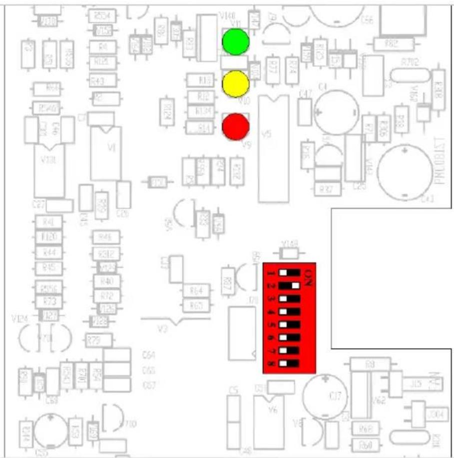
5.5 Configuration with DIP switches (see appendix D)
Some settings can be changed with DIP switches.
Procedure:
a) Turn the Compact on, preferably without load and without AC voltage on the inputs. The Compact will then operate in inverter mode.
b) Set the DIP switches as required.
c) Store the settings by moving DIP switch 8 to 'on' and back to 'off'.
5.5.1. DIP switch 1 and 2
Default setting: to operate the product with the 'On/Off/Charger Only' switch
ds 1: 'off'
ds 2: 'on'
The default setting is required when using the 'On/Off/Charger Only' switch in the front panel. This setting should also be used in setups with a GX device or VE.Bus Smart dongle when no additional Digital Multi Control panel or VE.Bus BMS is connected.
When a Digital Multi Control panel or a VE.Bus BMS is included please refer to the settings below.
Setting for remote operation with a Multi Control Panel or a VE.Bus BMS:
ds 1: 'on'
ds 2: 'off'
This setting is required when a Multi Control Panel and/or a VE.Bus BMS is connected. The Multi Control panel must be connected to one of the two RJ45 sockets B, see appendix A.
Setting for remote operation with a 3-way switch:
ds 1: 'off'
ds 2: 'off'
This setting is required when a 3-way switch is connected.
The 3-way switch must be wired to terminal H, see appendix C.
Only one remote control can be connected, i.e. either a switch or a remote control panel. In both cases the switch on the product itself should be 'on'.
5.5.2. DIP switch 3 to 7
These DIP switches can be used to set:
- Battery charge voltage and Absorption time
- Inverter frequency
- Search mode
- AC input current limit 12 A or 6 A
ds3-ds4: Setting charge voltages
| ds3-ds4 | Absorption voltage | Float voltage | Storage Voltage | Absorption Time (hours) | Suitable for |
| ds3=off | 14.4 | 13.8 | 13.2 | 8 | Gel Victron Deep Discharge |
| ds4=off (default) | 28.8 | 27.6 | 26.4 | Gel Exide A200 | |
| 57.6 | 55.2 | 52.8 | AGM Victron Deep Discharge | ||
| ds3=on | 14.1 | 13.8 | 13.2 | 8 | Gel Victron Long Life (OPzV) |
| ds4=off | 28.2 | 27.6 | 26.4 | Gel Exide A600 (OPzV) | |
| 56.4 | 55.2 | 52.8 | Gel MK battery | ||
| ds3=off | 14.7 | 13.8 | 13.2 | 5 | AGM Victron Deep Discharge |
| ds4=on | 29.4 | 27.6 | 26.4 | Tubular plate or OPzS batteries in semi-float mode | |
| 58.8 | 55.2 | 52.8 | AGM spiral cell | ||
| ds3=on | 15.0 | 13.8 | 13.2 | 6 | Tubular plate or OPzS batteries in cyclic mode |
| ds4=on | 30.0 | 27.6 | 26.4 | ||
| 60.0 | 55.2 | 52.8 |
Batteries with high antimony content can typically be charged with a lower absorption voltage than batteries with low antimony content. (Please refer to our book 'Electricity on Board' downloadable from our website www.victronenergy.com for details and suggestions about charging batteries). Contact your battery supplier for the correct charge voltages and change (with VE-configure) the voltage settings if required.
The default charge current setting is 75 % of the maximum charge current. This current will be too high for most applications.
For most battery types the optimal charge current is 0.1-0.2x the battery capacity.
ds5: Inverter frequency
$$ \mathrm{off} = 5 0 \mathrm{Hz} $$
$$ \mathrm{on} = 6 0 \mathrm{Hz} $$
ds6: Search Mode
$$ \mathrm{off} = \mathrm{off} $$
$$ \text {on} = \text {on} $$
ds7: AC input current limit
$$ \mathrm{off} = 1 2 \mathrm{Amp} $$
$$ \mathrm{on} = 4 \mathrm{Amp} $$
Store the settings by moving DIP switch 8 to 'on' and back to 'off'.
5.5.3 Exemplary settings
Example 1 is the factory setting (since factory settings are entered by computer, all DIP switches of a new product are set to 'off', except for DS-2).
| DS-1 Panel optionDS-2 Panel optionDS-3 Ch. voltageDS-4 Ch. voltageDS-5 FrequencyDS-6 Search modeDS-7 AC-in LimitDS-8 Store setting | 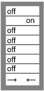 | DS-1DS-2DS-3DS-4DS-5DS-6DS-7DS-8 | 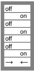 | DS-1DS-2DS-3DS-4DS-5DS-6DS-7DS-8 | 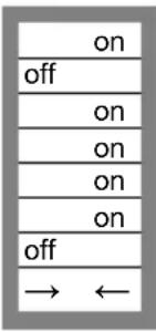 |
| Example 1: (factory setting)1 No panel or remoteswitch connected2 No panel or remoteswitch connected3, 4 GEL 14.4 V5 Frequency: 50 Hz6 Search mode off7 AC-in Limit 12 Amp8 Store setting: off→ on→ off | Example 21 No panel or remoteswitch connected2 No panel or remoteswitch connected3, 4 AGM 14,7 V5 Frequency: 50 Hz6 Search mode off7 AC-in Limit 4 Amp8 Store setting: off→ on→ off | Example 31 Panel or remoteswitch connected2 Panel or remoteswitch connected3, 4 Tubular plate 15 V5 Frequency: 60 Hz6 Search mode on7 AC-in Limit 12 Amp8 Store setting: off→ on→ off | |||
Store the settings (DS3-DS7) by changing switch ds-8 from 'off' to 'on', and then back to 'off'. The LEDs 'charger' and 'alarm' will flash to indicate acceptance of the settings.
6. TROUBLE SHOOTING TABLE – inverter/charger
Proceed as follows for quick detection of common faults.
DC loads must be disconnected from the batteries and the AC loads must be disconnected from the inverter before the inverter and/or battery charger is tested.
Consult your Victron Energy dealer if the fault cannot be resolved.
| Problem | Cause | Solution |
| The inverter fails to operate when switched on | The battery voltage is too high or too low | Ensure that the battery voltage is within the correct value |
| The inverter fails to operate | Processor in no function-mode | Disconnect mains voltage.Switch Front switch off, wait 4 secondsSwitch front switch on |
| The alarm LED flashes | Pre-alarm alt. 1. The DC input voltage is low | Charge the battery or check the battery connections |
| The alarm LED flashes | Pre-alarm alt. 2. The ambient temperature is too high | Place the inverter in a cool and well-ventilated room, or reduce the load |
| The alarm LED flashes | Pre-alarm alt. 3. The load on the inverter is higher than the nominal load | Reduce the load |
| The alarm LED flashes | Pre-alarm alt. 4. Voltage ripple on the DC input exceeds 1.25 Vrms | Check the battery cables and terminalsCheck the battery capacity; increase if necessary |
| The alarm LED flashes intermittently | Pre-alarm alt. 5. Low battery voltage and excessive load | Charge the batteries, reduce the load or install batteries with a higher capacity. Use shorter and/or thicker battery cables |
| The alarm LED is on | The inverter did cut out following a pre-alarm | Check the table for the appropriate course of action |
| The charger is not functioning | The AC input voltage or frequency is out of range | Ensure that the input voltage is between 185 VAC and 265 VAC, and that the frequency matches the setting |
| The thermal circuit breaker has tripped | Reset the 16 A thermal circuit breaker. | |
| The battery is not being charged fully | Incorrect charging current | Set the charging current at between 0.1 and 0.2x battery capacity |
| A defective battery connection | Check the battery terminals | |
| The absorption voltage has been set to an incorrect value | Adjust the absorption voltage to the correct value | |
| The float voltage has been set to an incorrect value | Adjust the float voltage to the correct value | |
| The internal DC fuse is defective | Inverter is damaged | |
| The battery is overcharged | The absorption voltage has been set to an incorrect value | Adjust the absorption voltage to the correct value |
| The float voltage has been set to an incorrect value | Adjust the float voltage to the correct value | |
| A defective battery | Replace the battery | |
| The battery is too small | Reduce the charging current or use a battery with a higher capacity | |
| The battery is too hot | Connect a temperature sensor | |
| Battery charge current drops to 0 when the absorption voltage is reached | Alt. 1: Battery overtemperature (>50 °C) | - Allow battery to cool down- Place battery in a cool environment- Check for shorted cells |
| Alt 2: Battery temperature sensor faulty | Unplug battery temperature sensor from the MultiPlus. Reset the MultiPlus by switching it off, then wait for 4 seconds and switch it on againIf the MultiPlus now charges normally, the battery temperature sensor is faulty and needs to be replaced |
7. INSTALLATION – solar charge controller
- Protect the solar modules from incident light during installation, e.g. cover them.
- Never touch uninsulated cable ends.
- Use only insulated tools.
7.1 Connection of the solar panels
Up to three strings of PV panels can be connected with three sets of MC4 (PV-ST01) PV connectors.
7.2 PV configuration
- The controller will operate only if the PV voltage exceeds battery voltage (Vbat).
- PV voltage must exceed Vbat + 5 V for the controller to start. Thereafter minimum PV voltage is Vbat + 1 V.
• Maximum open circuit PV voltage: 100 V
The controller can be used with any PV configuration that satisfies the three above mentioned conditions.
For example:
24 V battery and mono- or polycristalline panels
- Minimum number of cells in series: 72 (2x 12 V panel in series or 1x 24 V panel).
• Maximum: 144 cells.
Remark: at low temperature the open circuit voltage of a 144 cell solar array may exceed 100V, depending on local conditions and cell specifications. In that case the number of cells in series must be reduced.
7.3 Cable connection sequence (see figure 1)
First: connect the battery.
Second: connect the solar array (when connected with reverse polarity, the controller will heat up but will not charge the battery).
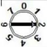
8. CONFIGURATION – the solar charge controller
Eight preprogrammed charge algorithms, selectable with a rotary switch:
| Pos | Suggested battery type | Absorption V | Float V | dV/dT mV/°C |
| 0 | Gel Victron long life (OPzV) Gel exide A600 (OPzV) Gel MK | 28.2 27.6 | -32 | |
| 1 | Gel Victron deep discharge Gel Exide A200 AGM Victron deep discharge Stationary tubular plate (OPzS) Rolls Marine (flooded) Rolls Solar (flooded) | 28.6 27.6 | -32 | |
| 2 | Default setting Gel Victron deep discharge Gel Exide A200 AGM Victron deep discharge Stationary tubular plate (OPzS) Rolls Marine (flooded) Rolls Solar (flooded) | 28.8 27.6 | -32 | |
| 3 | AGM spiral cell Stationary tubular plate (OPzS) Rolls AGM | 29.4 27.6 | -32 | |
| 4 | PzS tubular plate traction batteries or OPzS batteries | 29.8 | 27.6 | -32 |
| 5 | PzS tubular plate traction batteries or OPzS batteries | 30.2 | 27.6 | -32 |
| 6 | PzS tubular plate traction batteries or OPzS batteries | 30.6 | 27.6 | -32 |
| 7 | Lithium Iron Phosphate ( LiFePo_4 ) batteries | 28.4 27.0 | 0 |
After changing the position of the rotary switch, the LEDs will blink during 4 seconds as follows:
| Switch position | LED Float | LED Abs | LED Bulk | Blink Frequency |
| 0 | 1 | 1 | 1 | Fast |
| 1 | 0 | 0 | 1 | Slow |
| 2 | 0 | 1 | 0 | Slow |
| 3 | 0 | 1 | 1 | Slow |
| 4 | 1 | 0 | 0 | Slow |
| 5 | 1 | 0 | 1 | Slow |
| 6 | 1 | 1 | 0 | Slow |
| 7 | 1 | 1 | 1 | Slow |
Thereafter, normal indication resumes, as described below.
Remark: the blink function is enabled only when PV power is present on the input of the controller.
8.1 LEDs
Blue LED 'bulk': will be on when the battery has been connected. Switches off when the absorption voltage is reached.
Blue LED ‘absorption’: will be on when the absorption voltage is reached. Switches off at the end of the absorption period.
Blue LED 'float': will be on after the solar charger has switched to float.
8.2 Battery charging information
The charge controller starts a new charge cycle every moring, when the sun starts shining. The maximum duration of the absorption period is determined by the battery voltage measured just before the solar charger starts up in the morning:
| Battery voltage Vb (@start-up) | Maximum absorption time |
| Vb < 23.8 V 4 h | |
| 23.8 V < Vb < 24.4 V | 2 h |
| 24.4 V < Vb < 25.2 V | 1 h |
| Vb > 25.2 V 0 h |
If the absorption period is interrupted due to a cloud or due to a power-hungry load, the absorption process will resume when absorption voltage is reached again later on in the day, until the absorption period has been completed.
The absorption period also ends when the output current of the solar charger drops to less than 2 Amps, not because of low solar array output but because the battery is fully charged (tail current cut off).
This algorithm prevents over charge of the battery due to daily absorption charging when the system operates without load or with a small load.
8.3 Connectivity
Several parameters can be customized (VE.Direct to USB cable, ASS030530000, and a computer needed). See the data communication whitepaper on our website.
The required software can be downloaded from http://www.victronenergy.nl/support-and-downloads/software/
The charge controller can be connected to a Color Control panel, BPP000300100R, with a VE.Direct to VE.Direct cable.
9. TROUBLESHOOTING – solar charge controller
| Problem | Possible cause | Solution |
| Charger does not function | Reversed PV connection | Connect PV correctly |
| Reverse battery connection | Non replacable fuse blown Return to VE for repair | |
| The battery is not fully charged | A bad battery connection | Check battery connection |
| Cable losses too high | Use cables with larger cross | |
| Large ambient temperature difference between charger and battery | Make sure that ambient conditions are equal for charger and battery | |
| Only for a 24 V system: wrong system voltage chosen (12 V instead of 24 V) by the charge controller | Disconnect PV and battery, after making sure that the battery voltage is at least >19 V, reconnect properly (reconnect battery first) | |
| The battery is being overcharged | A battery cell is defect | Replace battery |
| Large ambient temperature difference between charger and battery (Tambient_chrg < Tambient_batt) | Make sure that ambient conditions are equal for charger and battery |
10. MAINTENANCE
This product does not require specific maintenance. It will suffice to check all connections once a year. Avoid moisture and oil/soot/vapours and keep the device clean.
- TECHNICAL DATA
| EasySolar | EasySolar 12/1600/70 | EasySolar 24/1600/40 |
| Inverter/charger | ||
| PowerControl / PowerAssist | Yes | |
| Transfer switch | 16 A | |
| INVERTER | ||
| Input voltage range | 9,5 – 17 V | 19 – 33 V |
| ‘Heavy duty’ output AC 0 16 A | ||
| Output AC1, 2, 3 | Output voltage: 230 VAC ± 2 %Frequency: 50 Hz ± 0,1 % (1) | |
| Cont. output power at 25 °C (3) | 1600 VA / 1300 W | |
| Cont. output power at 40 °C 1200 W | ||
| Peak power | 3000 W | |
| Maximum efficiency | 92 % | 94 % |
| Zero-load power | 8 W | 10 W |
| Zero-load power in search mode | 2 W | 3 W |
| CHARGER | ||
| AC Input | Input voltage range: 187-265 VACInput frequency: 45 – 65 Hz Power factor: 1 | |
| Charge voltage 'absorption' 14,4 / 28,8 V | ||
| Charge voltage 'float' | 13,8 / 27,6 V | |
| Storage mode | 13,2 / 26,4 V | |
| Charge current house battery (4) | 70 A | 40 A |
| Battery temperature sensor | yes | |
| Programmable relay (5) yes | ||
| Protection (2) | a - g | |
| Solar Charge Controller | ||
| Maximum battery current | 50 A | |
| Maximum PV power, 6 a,b) | 700 W | 1400 W |
| Maximum PV open circuit voltage | 100 V | 100 V |
| Maximum efficiency 98 % | ||
| Self-consumption | 10 mA | |
| Charge voltage 'absorption', default setting | 14,4 V 28,8 V | |
| Charge voltage 'float', default setting | 13,8 V | 27,6 V |
| Charge algorithm | multi-stage adaptive | |
| Temperature compensation | -16 mV / °C resp. -32 mV / °C | |
| Protection a – g | ||
| Common Characteristics | |
| Operating temp. range | -20 to +50 °C (fan assisted cooling) |
| Humidity (non condensing): | max 95 % |
| ENCLOSURE | |
| Material & Colour aluminium (blue RAL 5012) | |
| Protection category IP21 | |
| Battery-connection | Battery cables of 1.5 meter |
| PV connection | Three sets of MC4 (PV-ST01) PV connectors |
| 230 VAC-connection | G-ST18i connector |
| Weight | 11,7 kg |
| Dimensions (hxwxd) | 745 x 214 x 110 mm |
| STANDARDS | |
| Safety | EN 60335-1, EN 60335-2-29, EN 62109 |
| Emission / Immunity | EN 55014-1, EN 55014-2, EN 61000-3-3 |
| Automotive Directive 2004/104/EC | |
1) Can be adjusted to 60 Hz and to 240 V
2) Protection
a. Output short circuit
b. Overload
c. Battery voltage too high
d. Battery voltage too low
e. Temperature too high
f. 230 VAC on inverter output
g. Input voltage ripple too high
3) Non linear load, crest factor 3:1
4) At 25 °C ambient
5) Programmable relay which can be set for general alarm, DC undervoltage or genset start signal function
6a) If more PV power is connected, the controller will limit input power to 720 W resp. 1440 W.
6b) PV voltage must exceed Vbat + 5 V for the controller to start.
Thereafter minimum PV voltage is Vbat + 1 V.
Omvormer/lader: MultiPlus Compact 12/1600/70 of 24/1600/40
Wisselstroomverdeling
3.1 Schakelaar on/off/charger only
AES (Automatic Economy Switch)
Zie 'tubular plate traction battery charge curve' in VEConfigure.
Absorptietijd
Algorithm de charge souple
AES (Automatic Economy Switch)
AES (Automatic Economy Switch)
$$ \text { on } = \text { on } $$
$$ \text { on } = \text { on } $$
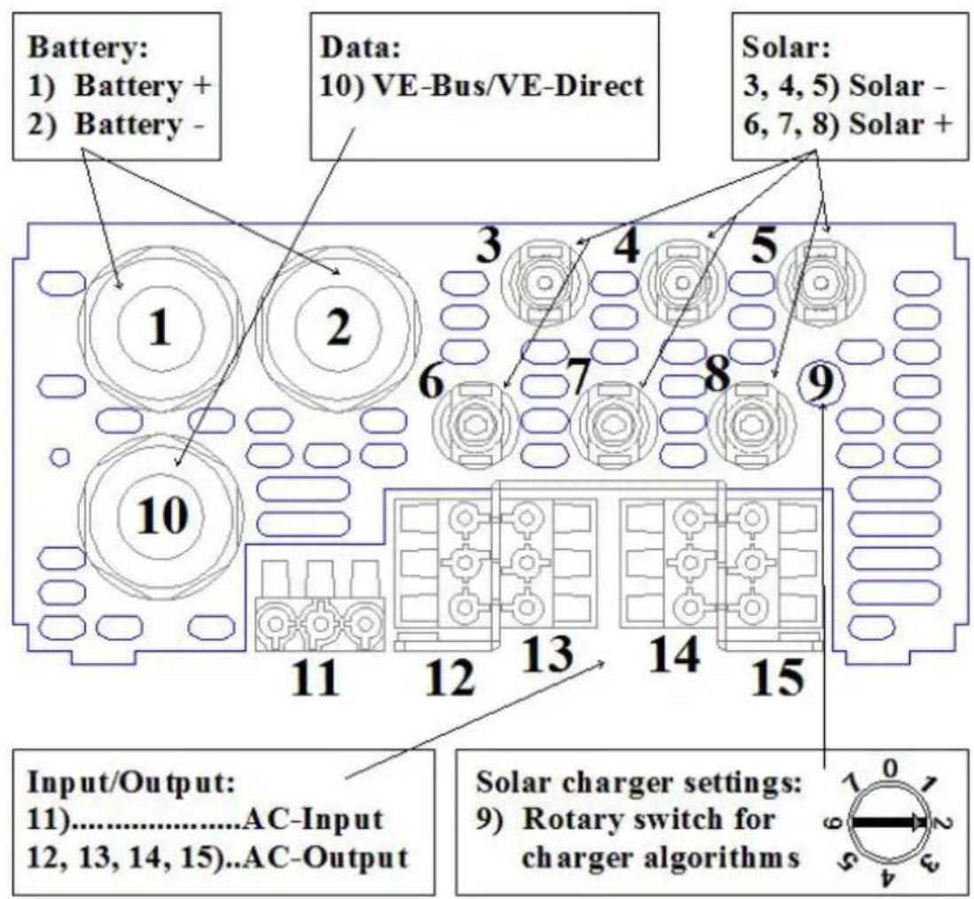
Appendix A: overview connections
| EN | NL |
| Battery:1) Battery + 2) Battery - | Accu:1) Accu + 2) Accu - |
| Data:10) VE-Bus/VE-Direct | Data:10) VE-Bus/VE-Direct |
| Solar:3, 4, 5) Solar – 6, 7, 8) Solar + | Zonne-energie:3, 4, 5) Zonne-energie – 6, 7, 8) Zonne-energie + |
| Input/Output:11) AC-Input 12, 13, 14, 15) AC-Output | Ingang/Uitgang:11) AC-Ingang 12, 13, 14, 15) AC-Uitgang |
| Solar charger settings:9) Rotary switch for charger algorithms | Instellingen zonnelader:9) Draaischakelaar voor laadalgoritmes |
| Female GST 18 connector “AC-In” | Vrouwelijke GST 18-aansluiting “AC-In” |
| Male GST 18 connector “AC-In” | Mannelijke GST 18-aansluiting “AC-In” |
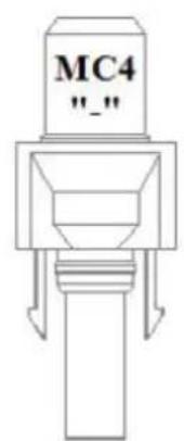
| MC4 “-” | MC4 “-” |
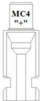
| MC4 “+” | MC4 “+” |
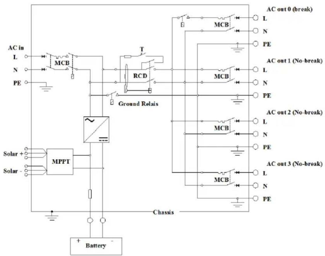
Appendix B: installation information
flowchart
graph TD
    A["AC in"] --> B["L"]
    A --> C["N"]
    A --> D["PE"]
    B --> E["MCB"]
    C --> F["T"]
    D --> G["RCD"]
    E --> H["Ground Relais"]
    F --> H
    G --> H
    H --> I["MCB"]
    I --> J["AC out 0 (break)"]
    I --> K["AC out 1 (No-break)"]
    I --> L["AC out 2 (No-break)"]
    I --> M["AC out 3 (No-break)"]
    M --> N["MCB"]
    N --> O["AC out 0 (break)"]
    N --> P["AC out 1 (No-break)"]
    N --> Q["AC out 2 (No-break)"]
    N --> R["AC out 3 (No-break)"]
    R --> S["MCB"]
    S --> T["AC out 0 (break)"]
    S --> U["AC out 1 (No-break)"]
    S --> V["AC out 2 (No-break)"]
    S --> W["AC out 3 (No-break)"]
    W --> X["MCB"]
    X --> Y["AC out 0 (break)"]
    X --> Z["AC out 1 (No-break)"]
    X --> AA["AC out 2 (No-break)"]
    X --> AB["AC out 3 (No-break)"]
    AC["Solar +"] --> AD["MPPT"]
    AE["Solar -"] --> AD
    AD --> AF["Chassis"]
    AG["Battery"] --> AH["+ Battery -"]
| EN | NL |
| AC-in | AC-in |
| Solar | Zonnepaneel |
| AC out 0 (break) | AC-uit 0 (break) |
| AC out 1 (No-break) | AC-uit 1 (No-break) |
| AC out 2 (No-break) | AC 2 (No-break) |
| AC out 3 (No-break) | AC-uit 3 (No-break) |
| Chassis | Chassis |
| Battery | Accu |
| FR | DE |
| AC-in | AC-Ein |
| Solaire | Solar |
| AC-out 0 (coupure) | AC Aus 0 (Unterbrechung) |
| AC-out 1 (pas de coupure) | AC Aus 1 (Keine Unterbrechung) |
| AC-out 2 (pas de coupure) | AC Aus 2 (Keine Unterbrechung) |
| AC-out 3 (pas de coupure) | AC Aus 3 (Keine Unterbrechung) |
| Boitier | Gehäuse |
| Batterie | Batterie |
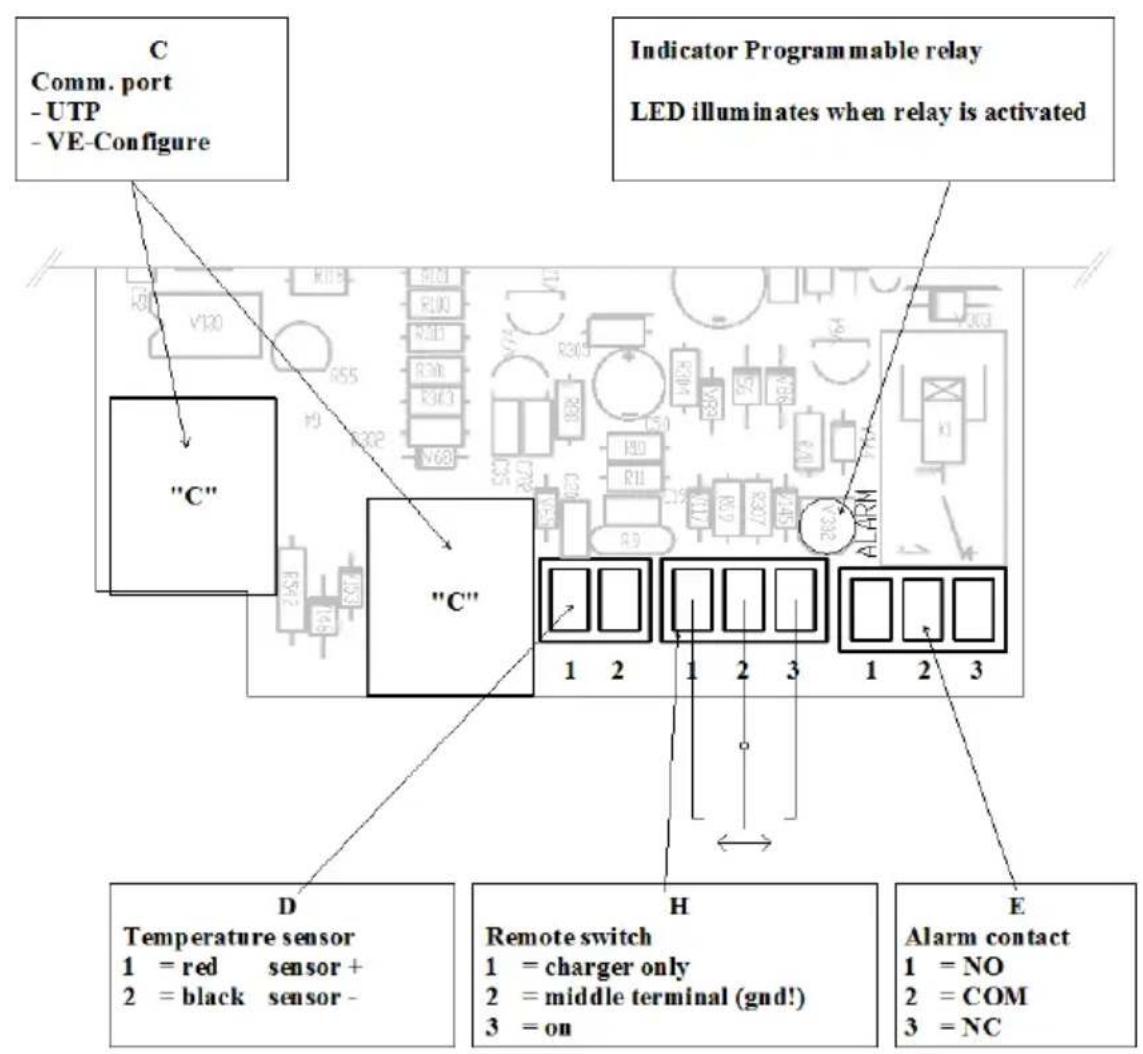
Appendix C: Inverter PCB connections
| EN | NL |
| C: Comm. Port-UTP - VE-Configure | C: Comm. Poort-UTP - VE-Configure |
| Indicator programmable relayLED illuminates when relay is activated | Indicator programeerbare relaisLED licht op wanneer het relais geactiveerd wordt |
| D: Temperature sensor1 = red sensor + 2 = black sensor – | D: Temperatuursensor1 = rode sensor + 2 = zwarte sensor – |
| H : Remote switch1 = charger only 2 = middle terminal (gnd !) 3 = on | H : Externe schakelaar1 = alleen lader 2 = middenterminal (aarding!)3 = aan |
| E : Alarm contact1 = NO 2 = COM 3 = NC | E : Alarmcontact1 = NEE 2 = COM 3 = NC |
| FR | DE |
| C: Port de Comm. --UTP - VE-Configure | C: Comm. Anschluss-UTP - VE-Configure |
| Indicateur Relais programmableLa LED s'allume quand le relais est activé | Anzeige programmierbares RelaisLED leuchtet bei aktiviertem Relais |
| D: Sonde de température1 = Rouge Sonde + 2 = Noir Sonde - | D: Temperatur-Sensor1 = roter Sensor + 2 = schwarzer Sensor - |
| H: Interrupteur à distance1 = chargeur uniquement 2 = borne du milieu (terre !) 3 = on | H: Fernst.-Schalter1 = nur Ladegerät 2 = mittlerer Anschluss (Erde!)3 = an |
| E: Contact alarme1 = NO 2 = COM 3 = NC | E: Alarm-Kontakt1 = NO 2 = COM 3 = NC |
| ES | IT |
| C: Puerto de comunicaciones-UTP - VE-Configure | C: Porta Com.-UTP - VE-Configure |
| Indicador del relé programableEI LED se ilumina al activarse el relé | Indicatore relè programmabileIl LED si accende quando il relè è attivo |
| D: Sensor de temperatura1 = rojo sensor + 2 = negro sensor – | D: Sensore temperatura1 = sensore rosso + 2 = sensore nero – |
| H : Interruptor remoto1 = sólo cargador 2 = terminal medio (imasa!) 3 = encendido | H : Interruttore remoto1 = solo caricatore 2 = terminale intermedio (gnd !)3 = on |
| E : Contacto de la alarma1 = NO 2 = COM 3 = NC | E : Contatto allarme1 = NO 2 = COM 3 = NC |
Appendix D: DIP switches
Victron Energy Blue Power
Distributor:
Serial number:
Version : 09
Date : June 9
^th , 2022
Victron Energy B.V.
De Paal 35 | 1351 JG Almere
PO Box 50016 | 1305 AA Almere | The Netherlands
: sales@victronenergy.com
www.victronenergy.com

- SAFETY INSTRUCTIONS
- General
- WARNING: ELECTRIC SHOCK HAZARD.
- Installation
- Transport and Storage
- DESCRIPTION
- General
- All-in-one solar power solution
- Solar charge controller: SmartSolar MPPT 100/50
- Inverter/charger: MultiPlus Compact 12/1600/70 or 24/1600/40
- AC distribution
- PowerAssist
- Inverter
- MultiPlus Compact-functional
- Uninterrupted AC power
- PowerControl – Dealing with limited generator or shore side power
- PowerAssist – Boosting the capacity of shore or generator power
- Programmable relay
- Battery Charger
- Adaptive 4-stage charge characteristic: bulk – absorption – float – storage
- The right amount of charge: variable absorption time
- Preventing damage due to excessive gassing: the BatterySafe mode
- Less maintenance and aging when the battery is not in use: the Storage mode
- To increase battery life: temperature compensation
- Learn more about batteries and battery charging
- Charge Controller MPPT 100/50
- Charge current up to 50 A and PV voltage up to 100 V
- Ultra-fast Maximum Power Point Tracking (MPPT)
- Advanced Maximum Power Point Detection in case of partial shading conditions
- Outstanding conversion efficiency
- Flexible charge algorithm
- Extensive electronic protection
- Internal temperature sensor
- Adaptive three step charging
- Bulk stage
- Absorption stage
- Float stage
- Configuration Assistants
- OPERATION – inverter/charger
- On/Off/Charger Only Switch
- Remote control
- Equalisation and forced absorption
- Equalisation
- Forced absorption
- Activating equalisation or forced absorption
- Procedure:
- LED Indications
- Inverter
- Charger
- INSTALLATION – inverter/charger
- Location
- Connection of Battery cables (see appendix A)
- Procedure
- Connection of the AC cabling
- Optional Connections
- Second Battery
- Temperature Sensor
- Remote Control panel & remote on/off switch
- Programmable relay
- CONFIGURATION – inverter/charger
- Standard settings: ready for use
- Explanation of settings
- Inverter frequency
- Input frequency range
- Input voltage range
- Inverter voltage
- AES (Automatic Economy Switch)
- Ground relay (see appendix B)
- Battery charge curve
- Battery type
- Automatic equalisation charging
- Absorption time
- Storage voltage, Repeated Absorption Time, Absorption Repeat Interval
- Bulk Protection
- AC input current limit
- Remark: lowest allowable current setting for PowerAssist: 2.7 A.
- UPS feature
- Dynamic current limiter
- WeakAC
- BoostFactor
- VEConfigure
- Configuration by computer
- VE.Bus Quick Configure Setup
- VE.Bus System Configurator
- Configuration with a VE.Net panel
- Configuration with DIP switches (see appendix D)
- DIP switch 1 and 2
- DIP switch 3 to 7
- Exemplary settings
- TROUBLE SHOOTING TABLE – inverter/charger
- INSTALLATION – solar charge controller
- Connection of the solar panels
- PV configuration
- For example:
- Cable connection sequence (see figure 1)
- CONFIGURATION – the solar charge controller
- LEDs
- Battery charging information
- Connectivity
- TROUBLESHOOTING – solar charge controller
- MAINTENANCE
- Omvormer/lader: MultiPlus Compact 12/1600/70 of 24/1600/40
- Wisselstroomverdeling
- Schakelaar on/off/charger only
- Absorptietijd
- Algorithm de charge souple
- Victron Energy Blue Power
Brand : VICTRON ENERGY
Model : EasySolar
Category : Battery charger