V300 - Video Intercom SOMFY - Free user manual and instructions
Find the device manual for free V300 SOMFY in PDF.
| Product type | Video intercom |
| Brand | Somfy |
| Model | V300 |
| Monitor dimensions (W x H x D) | 225 x 155 x 22 mm |
| Street panel dimensions (W x H x D) | 76 x 148 x 45 mm |
| Screen | 7 inches (17 cm), resolution 800 x 480 pixels |
| Monitor power supply | Power adapter 100-240 V / 50-60 Hz, output 17 Vdc, 1.1 A |
| Night vision | Infrared LEDs |
| Camera - Viewing angle | Horizontal 95°, Vertical 67° |
| Image memory | 100 photos (internal memory) |
| RTS radio transmitter | Frequency 433.42 MHz, power < 10 mW, range 200 m free field |
| Operating temperature - Monitor | -10°C to +55°C |
| Operating temperature - Street panel | -20°C to +55°C |
| Street panel outputs | 12 V, 800 mA electric strike; Dry contact (COM/NO) |
| Housing configuration | 1 or 2 possible dwellings |
| Wireless control | Somfy Radio Technology (RTS) for gate, shutter, lighting, etc. |
| Monitor mounting | Wall mount |
| Street panel mounting | Surface mounting with rain guard visor |
| Street panel materials | Aluminum and plastic |
| Main functions | Answer, open gate, unlock electric strike, control RTS, view/delete photos |
| Maintenance and cleaning | Dry soft cloth, no solvent; power off before cleaning |
| Safety | Do not let children play, respect privacy, use in accordance with the law |
| Warranty | 2 years from date of purchase |
| Kit contents | Monitor, mount, power adapter, street panel, visor, screws, Torx key, 2-dwelling button, manual |
Frequently Asked Questions - V300 SOMFY
User questions about V300 SOMFY
0 question about this device. Answer the ones you know or ask your own.
Ask a new question about this device
Download the instructions for your Video Intercom in PDF format for free! Find your manual V300 - SOMFY and take your electronic device back in hand. On this page are published all the documents necessary for the use of your device. V300 by SOMFY.
USER MANUAL V300 SOMFY
natural_image
Exterior view of a modern office building (no signage)1 - BIENVENUE 2
text_image
Diagram showing various electronic devices and components with numbered labels, including an open book, a circuit board, a screen, and a device labeled 'study'.natural_image
Illustration of a car above a vehicle with two circular windows, no text or symbols present.natural_image
Technical diagram showing assembly of screws into a device housing, with an inset close-up of the component detail (no text or symbols present)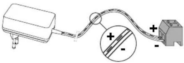
natural_image
Pure electrical circuit lines without any symbols
natural_image
Diagram of a laptop connected to an electronic device via cable, with a power outlet nearby (no text or symbols)natural_image
Diagram showing two configurations of cable or wire connections with no visible text or symbolsFR
V300
text_image
Technical diagram showing two views of a remote control device with labeled buttons and directional arrows indicating movement.natural_image
Top-down circular diagram with four concentric rings and a central spiral, no text or symbols present.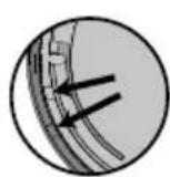


natural_image
Top-down schematic of a circular mechanical component with four concentric circular features (no text or symbols)


natural_image
Circular diagram with four concentric rings and four small circular elements, no text or symbols present.
natural_image
Three circular objects with different shading and label 'b c d', no text or symbols presentnatural_image
Cross-sectional diagram of a circular mechanical or architectural component with internal structural lines (no text or symbols)
text_image
b b c c d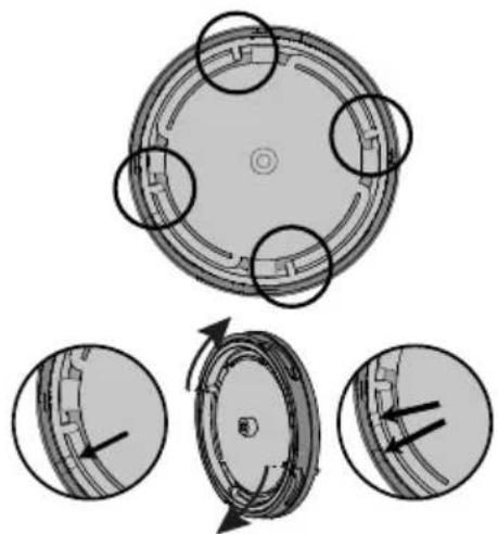
natural_image
Diagram of a circular mechanical component with four circular features, shown in three progressive views (no text or symbols)
text_image
Xooxx Honeytext_image
Diagram illustrating the working principle of a washing machine, showing components like fan, washer, and fan valve with directional arrows.
text_image
Hydroxide Sanly
text_image
Nonconcentive Equity
text_image
Diagram of a water level meter with labeled components and directional arrows indicating flow or movementtext_image
Diagram with labeled components and numbered circles, likely indicating parts of a system or layouttext_image
Diagram showing a device panel with labeled components and an inset circular view highlighting internal components.text_image
Technical diagram with labeled components and numbered parts, including a bottle, grid, and directional arrows9.1 Nettoyage
text_image
Diagram showing various electronic devices and components with numbered labels, including an open book, a circuit board, a screen, and a device labeled 'study'.natural_image
Technical line drawing of a mechanical assembly with screws and a magnified inset showing internal components (no text or symbols)
natural_image
Pure electrical circuit lines without any symbols
text_image
Diagram showing a device connected to a battery, with an arrow indicating direction of connection or operation.natural_image
Diagram of a cable connector with multiple wires, no text or symbols presentDE
text_image
Technical diagram showing two views of a device with labeled ports and directional arrows indicating movement or assembly.natural_image
Circular mechanical component with four circular features and a central textured area, no visible text or symbols.
natural_image
Three circular objects: a gray oval labeled 'b' and two white circles with a black border, arranged horizontally (no text or symbols beyond labels)natural_image
Circular diagram with two shaded segments and a central horizontal line, no text or symbols present.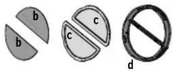
text_image
b b c c d
natural_image
Diagram of a circular mechanical component with four circular features, shown in three progressive views (no text or symbols)
natural_image
Simple line drawing of a container with a circular lid and a submerged object inside (no text or symbols)text_image
Diagram illustrating the working principle of a washing machine, showing components like fan, washer, and water level with directional arrows.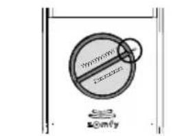
text_image
SYMBOL SNFY
text_image
Nonconvergent Bomly
text_image
Diagram with labeled components and numbered circles, likely indicating parts of a control or layout setup.text_image
Diagram showing a device panel with labeled components and an inset circular view highlighting internal components.7 - FUNKFERNSTEUERUNG VON SOMFY-RTS-GERÄTEN
text_image
Diagram showing labeled components with numbered annotations (15, 17, 16) and geometric shapes9.1 Reinigung
text_image
Exploded view diagram of a smart home control panel with numbered parts including reading, battery, and display unitnatural_image
Illustration of a car above a vehicle with two circular windows, no text or symbols present.natural_image
Technical diagram showing assembly of screws into a device housing, with an inset close-up of the component detail (no text or symbols present)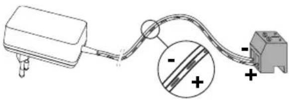
natural_image
Pure electrical circuit lines without any symbols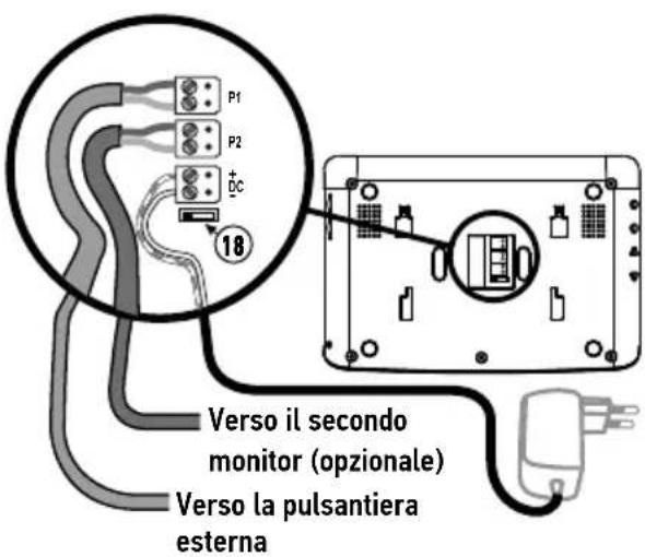
natural_image
Diagram showing a laptop connected to an electronic device via cable, with a power plug nearby (no text or symbols)natural_image
Diagram of a cable connector with wires, no text or symbols presentIT
[2]. Fissare la visiera parapioggia al muro/pilastro.
text_image
Technical diagram showing two views of a device with labeled ports and directional arrows indicating connection or movement.natural_image
Circular mechanical component with four circular features and a central textured area, no visible text or symbols.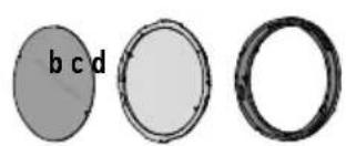
natural_image
Three circular objects with different shading and label 'b c d', no text or symbols presentnatural_image
Circular diagram with two shaded segments and a central horizontal line, no text or symbols present.
text_image
b b c c d
natural_image
Diagram of a circular mechanical component with four circular features, shown in three progressive views (no text or symbols)
natural_image
Simple line drawing of a container with a circular lid and a side panel, no text or symbols present.natural_image
Technical diagram showing mechanical components with circular and cross-sectional views, no visible text or symbols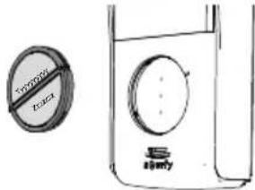
text_image
TOMATO Sally
text_image
Diagram with labeled components and numbered circles, likely indicating parts of a control or layout setup.text_image
Diagram showing a device panel with labeled components and an inset circular view highlighting internal components.text_image
Technical diagram with labeled components and numbered parts, including a bottle, grid, and directional arrows9.1 Pulizia
text_image
Exploded view diagram of a smart home control panel with numbered parts including reading, battery, and display unitnatural_image
Diagram of a car above a vehicle with two circular objects, no text or symbols presentnatural_image
Technical diagram showing assembly of screws into a device housing, with an inset close-up of the component detail (no text or symbols present)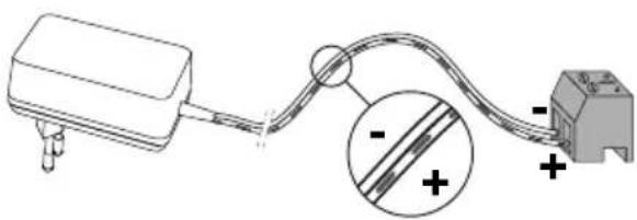
natural_image
Simple line drawing of a device connected to a terminal block, with an inset showing a magnified view of the cable (no text or symbols)
natural_image
Diagram of a device connected to a power outlet with an arrow indicating direction (no text or symbols present)natural_image
Diagram showing two configurations of cable or wire connections with no visible text or symbolsEL
natural_image
Diagram showing a device with a cable inserted into a control panel, connected by a wire (no text or symbols present)
natural_image
Line drawing of a portable electronic device with a circular dial and control knob, plus a small mechanical component below (no text or symbols)natural_image
Top-down circular diagram with four symmetrical segments and a central dot, no text or symbols present.

natural_image
Top-down schematic of a circular mechanical or electrical component with four concentric circular features (no text or symbols)


natural_image
Circular diagram with four concentric rings and four small circular elements, no text or symbols present.
natural_image
Three circular objects with different shading and label 'b c d', no text or symbols presentnatural_image
Circular diagram with two shaded segments and a central horizontal line, no text or symbols present.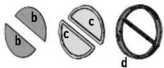
text_image
b b c c d
natural_image
Diagram of a circular mechanical component with four circular features, shown in three progressive views (no text or symbols)
natural_image
Simple line drawing of a container with a circular lid and a submerged object inside (no text or symbols)natural_image
Technical diagram showing mechanical components with circular and radial views, no visible text or symbols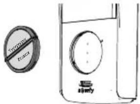
text_image
TROGOL TACA
text_image
Nonconcentive Equitytext_image
Technical diagram with labeled components and numbered parts, including a magnifying glass and grid patterntext_image
Diagram showing a device panel with labeled components and an inset circular view highlighting internal components.text_image
Diagram showing a device with 3s adjustment and a close-up of its internal components, likely illustrating a repair or cleaning process.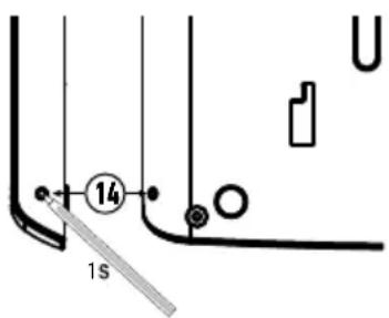
text_image
14 1stext_image
Technical diagram with labeled components and numbered parts, including a bottle, grid, and directional arrows9.1 Καθαρισμός
text_image
Exploded view diagram of a smart home control panel with numbered parts including open book, connected plug, display case, and screen.1 Monitor interior 1
natural_image
Illustration of a car above a vehicle with two circular components, no text or symbols present.natural_image
Technical diagram showing assembly of screws into a device housing, with an inset close-up of the component detail (no text or symbols present)
natural_image
Pure electrical circuit lines without any symbols
text_image
Diagram showing a device connected to a battery and a switch, with an arrow indicating direction of connection.natural_image
Two diagrams showing cable routing between a device with wires and connectors, no text or symbols present.ES
V300
text_image
Technical diagram showing two views of a device with labeled ports and directional arrows indicating assembly or operation.natural_image
Top-down circular diagram with four symmetrical segments and a central dot, no text or symbols present.

natural_image
Top-down schematic of a circular mechanical or electrical component with four concentric circular features (no text or symbols)


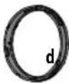
| a Placa de fondo |
| b Etiqueta |
| c Cristal |
| d Anillo |
a

d
natural_image
Circular mechanical component with four mounting holes and a central circular feature (no text or symbols)
natural_image
Three circular objects with different shading and label 'b c d', no text or symbols presentnatural_image
Circular diagram with two shaded segments and a central horizontal line, no text or symbols present.
text_image
b b c c d
natural_image
Diagram showing a circular mechanical component with four circular features, and three close-up views of the internal structure (no text or symbols)
text_image
Xooxx Santytext_image
Diagram illustrating the working principle of a washing machine, showing components like fan, washer, and water level with directional arrows.
text_image
Hydroxide Sanly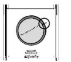
text_image
Non-convexing @2017
text_image
Diagram of a water tank with a circular valve and directional arrows indicating flow or movement, labeled in Chinese.text_image
Technical diagram with labeled components and numbered parts, including a magnifying glass and grid patterntext_image
Diagram showing a device panel with labeled components and an inset circular view highlighting internal components.7 - CONTROL INALÁMBRICO DE LOS EQUIPOS SOMFY RTS
text_image
somy BASO P1 RESET 14 1 S C A8 - USO
text_image
Diagram showing labeled components with numbered annotations (15, 17, 16) and a device icon9.1 Limpieza
text_image
Exploded view diagram of a smart home control panel with numbered parts including reading, battery, and display unitnatural_image
Illustration of a car above a vehicle with two circular windows, no text or symbols present.natural_image
Technical diagram showing assembly of screw fasteners into a device housing, with an inset close-up of the component detail (no text or symbols present)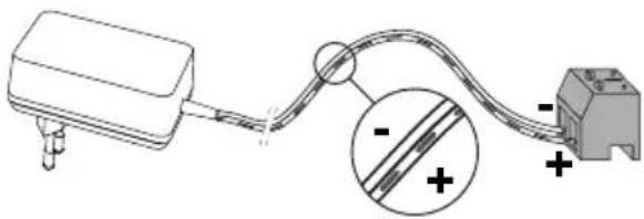
natural_image
Pure electrical circuit lines without any symbols
text_image
Diagram showing a device connected to a battery, with an arrow indicating direction of connection or operation.natural_image
Two technical diagrams showing cable routing between a device with wires and connectors, no text or symbols present.PT
V300
text_image
Technical diagram showing two views of a remote control device with labeled buttons and directional arrows indicating movement.natural_image
Top-down circular diagram with four symmetrical segments and a central dot, no text or symbols present.


natural_image
Top-down schematic of a circular mechanical or electrical component with four concentric circular features (no text or symbols)


| a Placa de fundo |
| b Etiqueta |
| c Vidro |
| d Anel |

a


d
natural_image
Circular diagram with two semicircular segments and a central horizontal line, no text or symbols present.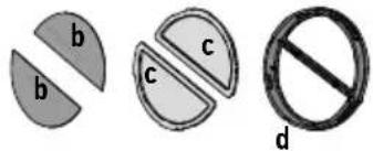
text_image
b b c c dtext_image
Diagram illustrating the working principle of a washing machine, showing components like fan, washer, and washing machine with labeled parts.
text_image
No Sign Somy
text_image
Diagram with labeled components and numbered circles, likely indicating parts of a system or layouttext_image
Diagram showing a device panel with labeled components and an inset circular view highlighting internal components.7 - COMANDO SEM FIOS DE EQUIPAMENTOS SOMFY RTS
text_image
somy BASO P1 RESET B 14 1 S C A8 - UTILIZAÇÃO
text_image
Diagram with labeled components and numbered annotations, including a bottle, grid, and circular elements1.1 Who is Somfy? 2
1.2 Assistance 2
1.3 Warranty 2
2 - IMPORTANT INFORMATION - SAFETY 2
2.1 General information 2
2.2 General safety instructions 2
2.3 Conditions of use 2
2.4 Recycling and disposal 3
2.5 Meaning of logos on the mains adaptor 3
3 - PRODUCT DESCRIPTION 3
3.1 Composition of the kit 3
3.2 Product description 4
3.3 Standard installation 6
4 - INSTALLING THE MONITOR 8
4.1 Installation for one residence 8
4.2 Installation for two residences 8
5 - INSTALLING THE DOOR STATION 9
5.1 Wiring the door station 9
5.2 Fitting the name plate 12
5.3 Switching the installation on 13
6 - SETTING THE VIDEOPHONE 14
6.1 Monitor 14
6.2 Door station 14
7 - WIRELESS CONTROL OF SOMFY RTS EQUIPMENT 15
7.1 Adding an RTS device (radio technology Somfy) 15
7.2 Removing Somfy RTS equipment 15
7.3 Programming a Somfy RTS gate motorisation with integrated wireless control 16
8 - USE 16
8.1 Responding to a visitor 16
8.2 Opening the gate 16
8.3 Unlocking the electric latch/lock 16
8.4 Wireless control of a Somfy RTS device via the monitor 17
8.5 Viewing / deleting photos 17
9 - MAINTENANCE 18
9.1 Cleaning 18
10 - TECHNICAL DATA 18
Thank you for choosing a Somfy product.
1.1 Who is Somfy?
Somfy develops, manufactures and sells motors and automatic control devices for domestic equipment. Motorisation systems for gates, garage doors and roller shutters, alarm systems, lighting controls, heating thermostats; all Somfy products are designed to meet your expectations in terms of safety, comfort and energy efficiency.
At Somfy, the pursuit of quality is a continuous process of improvement. Somfy's reputation has been built upon the reliability of its products and the Somfy brand is synonymous with innovation and technological expertise worldwide.
1.2 Assistance
Getting to know our customers, listening to them, meeting their needs: this is Somfy's approach.
For further information on how to choose, purchase or install Somfy products, please consult your retailer or contact a Somfy advisor directly for help and assistance.
This product is guaranteed for 2 years from the date of purchase.
2 - IMPORTANT INFORMATION - SAFETY
2.1 General information
Read this installation guide and the safety instructions carefully before installing this Somfy product.
All the instructions given must be followed closely and this guide must be stored in a safe place throughout the service life of your product.
Before installation, check that this Somfy product is compatible with the associated equipment and accessories.
These instructions describe how to install and use this product.
Any installation or use outside the field of application specified by Somfy is forbidden. This invalidates the Somfy warranty and discharges Somfy of all liability, as does any failure to comply with the instructions provided herein.
Somfy cannot be held responsible for changes to norms or standards occurring after the publication of these instructions.
Somfy hereby declares that this product is in compliance with the requirements of Directive 2014/53/EU. The full text of the Declaration of Conformity is available at www.somfy.com/ce
Non contractual images.
2.2 General safety instructions
Do not let children play with the control point.
Never immerse the control point in liquid.
This product is not designed to be used by persons (including children) with reduced physical, sensory or mental capacities, or persons lacking in experience or knowledge, unless they have received, from a person responsible for their safety, monitoring or prior instruction regarding the use of the product.
2.3 Conditions of use
The radio range is limited by radio appliance control standards.
The radio range is heavily dependent on the environment in which it is used: interference may be caused by having large-scale electrical equipment near the installation and by the type of material used in the walls and partitions.
The use of a radio appliances (e.g. a set of Hi-Fi radio headphones) operating on the same radio frequency might be detrimental to the product's performance.
The purpose of this videophone camera is to identify a visitor; under no circumstances should it be used to monitor the street.
This installation must be used in compliance with the data processing and civil liberties law.
Any use of these products which is not strictly personal is subject to statutory obligations of use and to obtaining the necessary administrative authorisations beforehand.
It is the buyer's civil and criminal liability in the event of misappropriate use of the device aimed at infringing the privacy or image of a third-party; Somfy will under no circumstances be held responsible for use of a videophone that violates current legal and regulatory provisions.
2.4 Recycling and disposal
Do not dispose of the product with household waste at the end of its life. Return the product to its distributor or use your local authority's special waste collection services.
2.5 Meaning of logos on the mains adaptor

The mains adaptor supplied with the product should only be used in a dry and sheltered place.

Direct current
The mains adaptor supplied with the product is the double-insulating type and therefore does not need to be connected to an earth conductor.

Alternating current
3 - PRODUCT DESCRIPTION
3.1 Composition of the kit

text_image
Exploded view diagram of a smart home control panel with numbered parts including open book, connected plug, display case, and screen.Mark Description Quantity
1 Indoor monitor 1
2 Monitor mounting bracket 1
3 Monitor mains adaptor 1
4 Door station (with button for 1 residence) 1
5 Rain shield 1
6 Screws + plugs for mounting the monitor and door station 5 + 5
7 Torx key 1
8 Button for 2 residences 1
9 Installation and user guide 1
3.2 Product description
The videophone comprises an indoor monitor and a door station. The indoor monitor can be connected to the door station by 2 wires and the electrical supply is wired through the monitor (see "3.3 Standard installation").
3.2.1 Monitor
The indoor monitor is fitted with an RTS (Radio Technology Somfy) radio transmitter. This wireless control function enables home products with a Somfy RTS receiver to be controlled (garage door, gate, lighting, roller shutters, awning, etc.).
The V300 offers the possibility of combining two separate residences and the possibility of installing an optional additional monitor for each residence. For this type of installation, see "4.2 Installation for two residences".
Note: before fastening the monitor in place, it is important to check that the radio range is sufficient to control all the desired RTS wireless products (in particular the gate) from the installation site.
text_image
225 155 ⑩ ① 5678 STOP SELECT ④ ③ ② #g#y3 ⑨ ⑪
text_image
22 12 13 14 19 18 20 15 17 16Mark Description Description
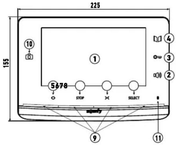
| 1 | Screen | Used to view the visitor. | |
| Wired controls | 2 | Microphone activation button | Activates the microphone on the monitor to speak to a visitor. |
| 3 | Electric latch/lock button | Controls the electric latch or lock. | |
| 4 | Gate button | Controls the motorised gate. | |
| Wireless controls | 5 | Open/on button | Opens the gate, roller shutter, awning or garage door or switches lighting on. |
| 6 | STOP button | Stops the movement of the gate, roller shutter, awning or garage door. | |
| 7 | Close/off button | Closes the gate, roller shutter, awning or garage door or switches lighting off. | |
| 8 | RTS channel selection button | Enables the radio channel controlling a product or a group of products to be selected (see “8.4 Wireless control of a Somfy RTS device via the monitor”). | |
| 9 | Channel indicator lights | Each indicator light represents one RTS (radio technology Somfy) channel. There are 5 channels in total: for the 5th channel, the 4 indicator lights are lit. | |
| 10 | Photo LED | The photo LED is lit in the event of a missed visit: a photo is recorded via the monitor for each unanswered call. | |
| 11 | Microphone | Enables you to talk to your guest in front of the door station. | |
| 12 | Bell volume | Bell volume setting thumb-wheel. | |
| 13 | Loud speaker volume | Speaker volume setting thumb-wheel. | |
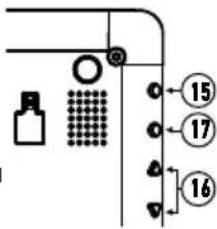
| 14 | PROG button | Enables the monitor to be programmed for wireless control of RTS (radio technology Somfy) equipment. | |
| 15 | MENU button | Activates the menu to adjust the brightness, contrast, etc. | |
| 16 | Settings buttons | Enable you to navigate through the menu when choosing your bell-tone (see “6.1.2 Changing the monitor bell-tone”) and when adjusting the monitor (contrast, brightness, etc.). |
| Mark Description Description | ||
| 17 | BACK button | Enables you to go back to a previous screen in the settings menu.Enables a screen shot to be taken during a conversation with a visitor.Enables the monitor bell-tone to be selected by keeping the button depressed. |
| 18 | Switch for 1 or 2 residences | Enables the installation to be set for one or two residences. |
| 19 | Terminal | Enables the monitor to be connected to the power supply, the door station and the additional monitor if it is installed. |
| 20 | Speaker | Allows the bell to be heard when activated as well as the voice of the visitor standing in front of the door station. |
3.2.2 Door station
The door station can be connected to a gate motorisation and an electric latch/lock (maximum 12 V AC/DC - 800 mA). The gate and the electric latch/lock can be activated independently via the videophone monitor, see "5.1.1 Connecting to a Somfy gate motorisation" and "5.1.2 Connecting to an electric latch/lock".

Mark Description Description
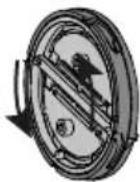
1 Rain shield Protects the camera from the rain and sun.
2 Camera Films the visitor and sends the image to the monitor.
3 IR LED lighting Enables visitors to be seen at night.
4 Microphone Enables the visitor to speak to the person indoors.
5 Speaker Enables the visitor to hear the person indoors.
| 6 | Back-lit name plateBack-lit call button | Indicates your name on a label.Visitors can use this button to ring the bell on the monitor. The camera and the monitor screen are switched on. |
| 7 | Speaker volume adjustment potentiometer | Used to adjust the volume of the door station speaker. |
| 8 | Call signal adjustment potentiometer | Used to adjust the volume of the call signal emitted by the door station speaker. |
| 9 Terminal block | Used to connect the monitor station to a gate motorisation or an electric latch/lock. | |
10 Anti-tamper screw Stops the door station from being opened without the Torx key provided.
3.3 Standard installation
3.3.1 For one residence
| Distance between the door station and the furthest monitor | Cable to be used | |
| A | Less than 50 m 2 wires of min. 0.5 mm^2 | |
| Between 50 and 100 m | 2 wires x 1 mm^2 | |
| B | 2 wires of min. 0.75 mm^2 | |
| C | 2 wires of min. 0.5 mm^2 | |
You are advised to use flexible cables and to tin the bare ends or fit them with end-pieces to be crimped.
The maximum wire section for the terminals is 1 mm ^4 .

text_image
100 m max. between the door station and the furthest monitor 230 Vac
text_image
Optional 30 max. 5 max. 230 V AC A C 230 V AC 5 max.Note: We recommend that the videophone cable and the motor cable(s) be installed in separate sheaths.
natural_image
Illustration of a car above a vehicle with two circular components, no text or symbols present.Note: If you need to use junction boxes to cable the videophone, use no more than two boxes between the door station and the monitor and no more than one box between the monitor and the mains adaptor.

flowchart
graph LR
    A["Power Supply Unit"] --> B["Switch 1"]
    B --> C["Switch 2"]
    C --> D["Switch 3"]
    D --> E["Monitor Display"]
    E --> F["Output Cable"]
3.3.2 For two residences
The videophone V300 also offers you the possibility of configuring the interphone for two separate residences. In this case, the 2 residences must be cabled using a junction box installed on the 2 wires leading from the door station fitted with two call buttons (see "4.2 Installation for two residences").
This configuration allows 1 additional monitor to be installed per residence.
Note: The monitor for the second residence is not provided in the initial pack.
text_image
Optional 30 max. A 230 V AC C A 230 V AC C Optional 5 max. A 230 V AC C A 230 V AC Note: We recommend that the videophone cable and the motor cable(s) be installed in separate sheaths. 100 m max. between the door station and the furthest monitor 230 Vac| Distance between the door station and the furthest monitor | Cable to be used | |
 | Less than 50 m 2 wires of | min. 0.5 mm^2 |
| Between 50 and 100 m 2 wires x 1 mm ^2 | ||
 | 2 wires of min. 0.75 mm^2 | |
 | 2 wires of min. 0.5 mm^2 | |
You are advised to use flexible cables and to tin the bare ends or fit them with end-pieces to be crimped.
The maximum wire section for the terminals is 1 mm ^4 .
A specific procedure must be followed to programme a SOMFY RTS gate motorisation sold in DIY stores in radio control mode. GATE MOTORISATIONS CONCERNED (after 2010):
• EVOLVIA, SGA and PASSEO 800 arm motors
• EXAVIA, SGS cylinder motors
• FREEVIA, SLIDYMOOVE sliding motors

Attention
The following procedure must be carried out before the final installation of the monitor (the monitor must be placed next to the gate motorisation while powered by means of its mains adaptor)"7.3 Programming a Somfy RTS gate motorisation with integrated wireless control".
4.1 Installation for one residence
[1]. Fix the monitor mounting plate to the wall.
Important: The monitor mounting brackets must come out towards you.
Note: All the wires must pass inside the mounting bracket so they can be connected to the monitor.
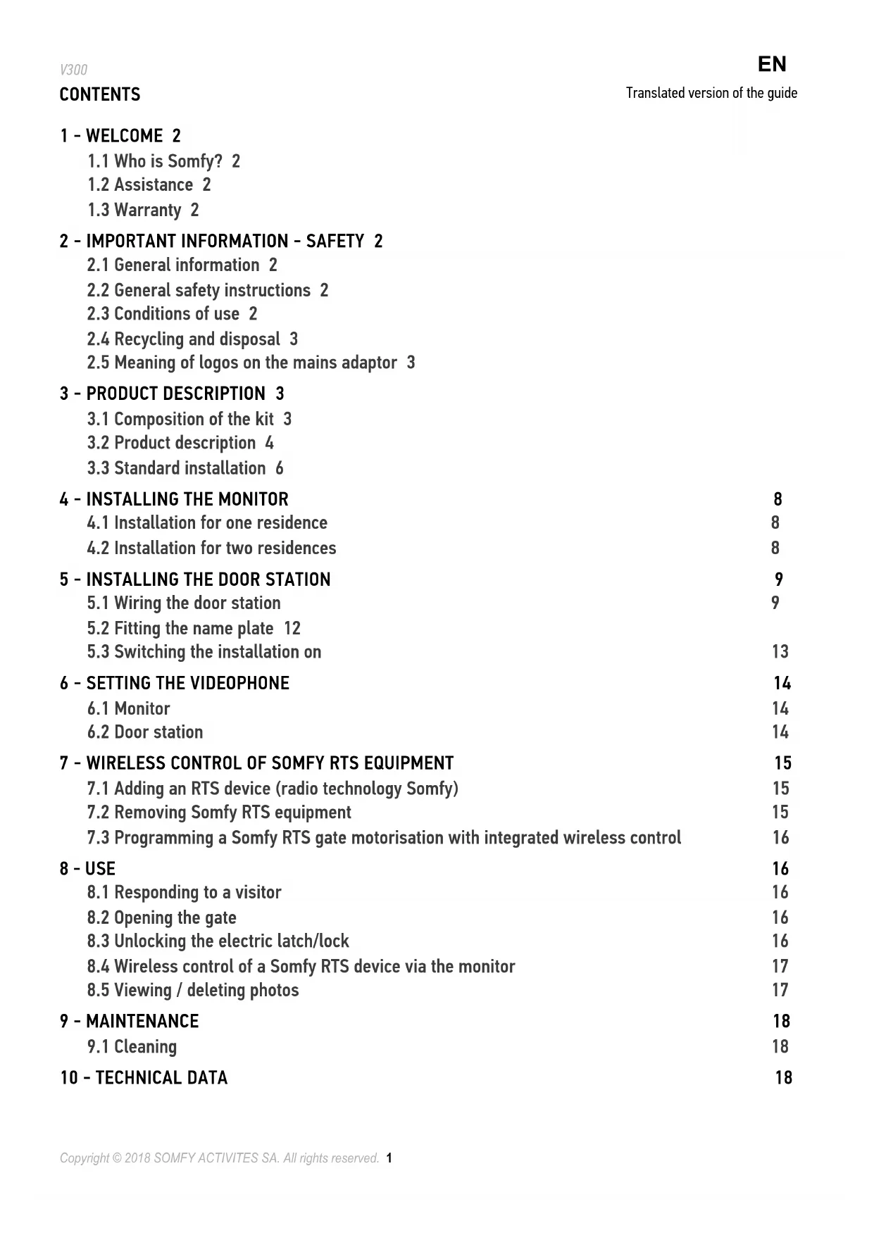
[2]. Remove the DC connector from the rear of the monitor, then connect the mains adaptor cable to this connector: white wire with grey lines at the top (+) and completely white wire at the bottom (-).
Important: It is essential to use the mains adaptor provided to power the monitor.
Important: The mains adaptor must be installed close to the monitor and must be easily accessible.
[3]. Connect the mains power adaptor connector to DC at the rear of the monitor as shown in the illustration (screw to the left).
Prepare the monitor for connection to the door station by connecting a 2-wire cable to connector P1 at the rear of the monitor.
If you wish to install a second monitor, prepare the connection for this monitor by connecting 2 wires to the P2 connector at the rear of the monitor, then refer to the guide for the second monitor for additional information on its wiring.
Note: For an installation for a single residence, the switch (18) must be set to position 2.


natural_image
Technical diagram showing screw fasteners and a component assembly with an inset close-up view (no text or labels)
natural_image
Pure electrical circuit lines without any symbols
text_image
P1 P2 BC 18 Towards the second monitor (optional) To the door station[4]. Clip the monitor onto its mounting bracket by first positioning the top of the monitor on the station, then the bottom.
Note: Position the mains power adapter wires between the mounting bracket and the monitor.

natural_image
Diagram showing a laptop connected to an electrical outlet with a power plug (no text or symbols)4.2 Installation for two residences
The V300 can be adapted to a two-residence format with a multi-button station. However, this type of installation requires the addition of a junction box (not supplied in the kit) to be placed between the door station and the monitors in each (see diagram below).
The monitors are installed as per the standard installation (see "4.1 Installation for one residence") with a maximum distance of 100 m between the door station and the monitor furthest away. Before installing the monitors, the switch (18) at the rear of the monitors must be configured to distinguish between the two residences and thus be able to use the two call buttons on the door station:
text_image
6-1 6-2 seny Call button for residence 1 6-2 Call button for residence 2 Residence 1 18 Residence 2 18 2 1 25 - INSTALLING THE DOOR STATION
Avoid installing the camera facing a light source, as images of visitors may be impaired.
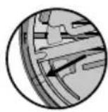
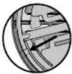
We recommend that a silicon seal be applied between the rain shield and the wall/pillar (but not on the lower section of the rain shield) and that the door station be fitted at a height of approximately 1.60 m.
5.1 Wiring the door station
[1]. Identify the mounting points with the rain shield. Drill and fit plugs suitable for your wall/pillar. Route all the cables into the rain shield.
[2]. Fix the rain shield to the wall/pillar.

natural_image
Two diagrams showing cable routing between a device with wires, no text or symbols presentEN
V300
[3]. Connect the monitor wires to the 2 terminals on the rear left-hand side of the door station:
-M+ of the monitor to M+ of the door station
-M- on the monitor to M- on the door station
Connect the electrical latch/lock wires to the + and - terminals on the door station.
Connect the motorisation wires to the door station's dry contact output (COM and NO).
Note: To feed the wires into the terminals, use a flat screwdriver to press on the square with the notch, feed the wires in, then release.

text_image
Monitor cable Gate motorisation cable Electric latch/lock cable M+ M- NO COM NC + - -[4]. The door station is supplied with the call button for 1 residence. If the installation includes two separate residences, the switch at the rear of the monitors must be positioned as shown in section "4.2 Installation for two residences" and the two call buttons supplied with the kit must be used (see "5.2 Fitting the name plate").
[5]. Position the door station in the rain shield.
[6]. Secure the door station to the rain shield by tightening the screw supplied using the Torx key.
text_image
Technical diagram showing two views of a device with labeled ports and directional arrows indicating assembly or operation.5.1.1 Connecting to a Somfy gate motorisation
Note: When the motorisation is solar-powered, the wired controls are deactivated. In this case, you must use the monitor's wireless control to control your gate motorisation: see "7.1 Adding an RTS device (radio technology Somfy)".
[1]. Disconnect the motorisation from the mains power supply.
[2]. Remove the cover from the control cabinet or from the motor containing the electronics.
[3]. Connect the door station dry contact output (COM and NO) to the motorisation electronics. It is best to consult the gate motorisation instructions when connecting a key-operated switch.
 | Somfy motorisations electronics | ||
 |  |  | |
| Connect... to the START termin- | inals | to the BUS termi-nals | to the numbered terminals |
| COM 533 | |||
| NO 64 | 5 (for complete opening)or6 (for pedestrian opening) | ||
Note: To connect the door station to another gate motorisation model, please consult the installation guide for this motorisation or contact your installer if it is a motorisation installed by a professional installer.
5.1.2 Connecting to an electric latch/lock
Connect the door station "+" and "-" terminals to the latch/lock in accordance with the diagram opposite.
Observe the +/- polarity if indicated in the latch/lock instructions.
text_image
M+ M- N C COM NC 800 mA maxEN
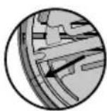
5.2 Fitting the name plate


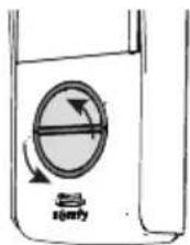
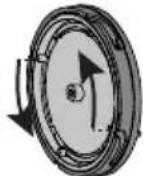
[1]. Press and turn the button anticlockwise until the stop block using the button lugs.
[2]. Lift the button to remove it, as the name plate holder is placed behind the base plate of the button.
[3]. Remove the button by turning the base plate anticlockwise until the stop block using the small lugs inside this plate.
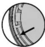
Note: When the base plate is in the unlocked position, the marker on the base plate and the ring are aligned.


natural_image
Top-down circular diagram with four symmetrical segments and a central dot, no text or symbols present.


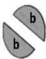
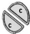
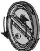
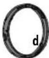
| a Base plate |
| b Name plate |
| c Glass |
| d Ring |

natural_image
Top-down schematic of a circular mechanical or electrical component with four concentric circular features (no text or symbols)


a


d
[4]. Write your name on the white name plate using a permanent marker:
- ensuring that you align the name with the cutaways on the name plate for the one-residence button,
- paying attention to the reading direction of each name plate for the two-residence button.
Note: the name plate holder has two cutaways that correspond to lugs located behind the name plate holder.


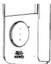
[5]. Replace the glass in the ring. Attention: for the 1-button version, there is a guide lug which allows the glass to be fitted in one single position only.
[6]. Replace the name plate in the button.
[7]. Replace the base plate: align the markers on the base plate and the ring and turn the base plate clockwise (using the lugs on the plate) until the stop block.

natural_image
Circular diagram with two semicircular segments and internal lines, no text or symbols present
text_image
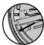
b b c c d[8]. Replace the button on the door station: align the lug on the ring with the marker on the door station and turn clockwise until locked.
If the button does not fit back into the door station, rotate it half a turn.

text_image
Diagram illustrating the working principle of a washing machine, showing steps from inner casing to back panel with labeled components.5.3 Switching the installation on
Once installation is complete, reconnect the gate motorisation to the power supply.
Next connect the monitor mains adaptor to an electrical socket.
6.1 Monitor
| 12 Bell volume dial | This is used to adjust the volume of the monitor bell. | |
| 13 | -00+ | Speaker volume dial This is used to adjust the volume of the monitor. |

text_image
12 136.1.1 Adjusting the screen
[1]. Press the "Menu" button (15).
[2]. Press briefly on the "Menu" button to navigate through the settings menu: the setting selected is highlighted in orange.
[3]. Press the settings buttons (16) to change the value of the parameter selected (brightness, contrast, menu language, time or date) until the desired setting is obtained.
[4]. Press the "Back" button (17) to exit the menu.
text_image
Technical diagram with labeled components and numbered parts, including a magnified inset showing circular features.6.1.2 Changing the monitor bell-tone
16 bell-tones are available on the monitor.
To change the monitor bell-tone, keep the "BACK" button (17) depressed (approx. 5 seconds). The default or previous bell-tone is played. You can then listen to the other bell-tones using the "settings buttons". Once you have made your choice, press the "Back" button briefly to save the new bell-tone.
6.2 Door station
6.2.1 Adjusting the speaker volume
To adjust the door station speaker volume, use a screwdriver to turn the bottom potentiometer (7) at the rear of the door station:
- clockwise to increase the volume,
- anti-clockwise to reduce the volume.
6.2.2 Setting the bell tone volume from the door station
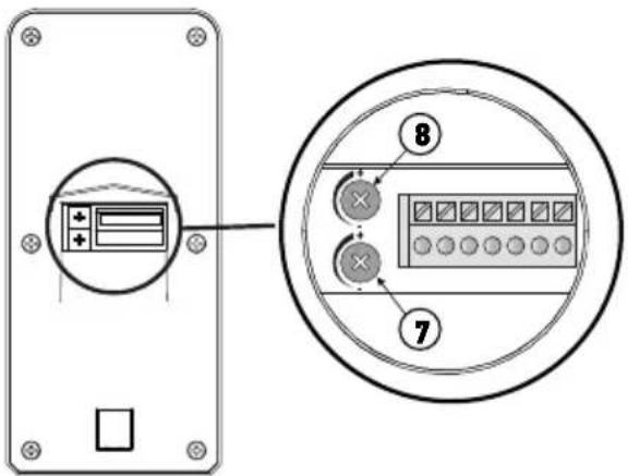
To adjust the door station bell-tone volume, use a screwdriver to turn the top potentiometer (8) at the rear of the door station:
- clockwise to increase the volume,
- anti-clockwise to reduce the volume.
text_image
Diagram showing a device panel with labeled components and an inset circular view highlighting internal components.The monitor is equipped with a Somfy Radio Technology (RTS) transmitter. It is only compatible with devices equipped with Somfy Radio Technology (RTS).
It is used to control the following Somfy equipment, individually or simultaneously:
- gate motorisation. (for a SOMFY RTS gate motorisation sold in a DIY store, see "7.3.1 Saving the gate motorisation in the monitor's memory"),
-Etc.
This functionality is possible thanks to a system of radio channels identified by indicator lights at the bottom of the monitor. Each channel corresponds to an individual remote control and can be used to control one or more devices. There is no limit to the number of devices that can be controlled by a single channel. To control a channel, simply press one of the “open/on” (5), “stop” (6) or “close/off” (7) buttons.
Important: Check that the equipment to be controlled is wireless and within the radio range of the monitor.
7.1 Adding an RTS device (radio technology Somfy)
To add an RTS device (radio technology Somfy), you must carry out 2 steps:
- identify the original RTS control for the equipment (remote control, transmitter, etc.)
-pair the monitor with the RTS device on the channel of your choice
7.1.1 Example: Adding a Somfy RTS roller shutter
[1]. Identify the original control of the roller shutter, i.e. the remote control or the control point which only controls this roller shutter.
Note:
- If the original control is lost or broken, and it is the only one that controls the roller shutter, contact one of our Somfy advisers.
- If another control operates the roller shutter, use that to follow the steps below.
[2]. Partially open the roller shutter using the original control.
[3]. Press the original control's PROG button for at least 3 seconds: the product reacts (for example, with a brief up and down movement or a series of 3 BEEPS). The programming function is activated for 2 minutes.
Note: If you cannot locate the PROG button on your control point, refer to the instructions.
[4]. Select a free channel by pressing the "SELECT" button (8) on the monitor.
[5]. Press the PROG button (14), located at the bottom right of the monitor, for 1 second.
[6]. Check that pairing has worked by pressing an open or close button.
Specific case: adding an already occupied radio channel
You can save more than one item of Somfy RTS equipment on the same radio channel to create groups of equipment. All equipment configured on the same channel then functions together.
To add a device, follow the procedure explained previously ("7.1 Adding an RTS device (radio technology Somfy)"). When you are asked to select an already occupied channel, choose the already occupied channel.
Note: It is recommended for optimum ergonomics, to group all equipment of the same type together on a single radio channel.
Individual RTS control point

text_image
3s 3s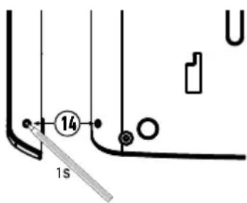
text_image
14 1s7.2 Removing Somfy RTS equipment
It is possible to delete control of a Somfy RTS device: when a device is already paired to the monitor, beginning the procedure described above again cancels the pairing.
7.3 Programming a Somfy RTS gate motorisation with integrated wireless control
GATE MOTORISATIONS CONCERNED (after 2010):
-EVOLVIA, SGA and PASSEO 800 arm motors
-EXAVIA, SGS cylinder motors
-FREEVIA, SLIDYMOOVE sliding motors
7.3.1 Saving the gate motorisation in the monitor's memory
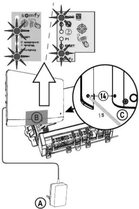
- Bring the monitor to the gate motorisation and connect it using the mains adaptor (A).
- Open the motorisation cover to access the electronics
- Press on the power button of your electronics for 2 seconds (if this
button does not exist, continue directly to the next step). The indicator light is lit on the electronics.
- Place the lower central section of the monitor on the motorisation electronics target (B).
- Select a free channel on the monitor and press the PROG button (14), located at the bottom right of the monitor (C), for 1 second.
The indicator light for the motorisation comes on then

goes out.
- The motorisation is now saved in the monitor's memory. You can control the opening and closing of your gate using the wireless control.
For more details, consult section concerning "Adding a 3-button remote control" in the instruction manual of your SOMFY motorisation.
text_image
somyf B P1 RESET BMO 14 1S C A8 - USE
8.1 Responding to a visitor
When a visitor presses the call button on the door station, the monitor plays the bell-tone selected an image of the visitor is displayed.
Press the microphone and speaker activation button
You can communicate with your visitor.
Note: The V300 offers the possibility of taking a screen shot during a conversation with a visitor by pressing the "Back" button (17) on your monitor briefly during the conversation. A pictogram appears at the top of the screen to indicate that the action is confirmed. The photo is then archived in the photo menu, see "8.5 Viewing / deleting photos".
Note: You can communicate with your visitor for a maximum of 2 minutes.
If you press the microphone and speaker activation button 📄 again, the monitor screen goes off and communication is cut off.
8.2 Opening the gate
With the monitor screen switched on or off, press the button
If the monitor screen is on, it will switch off when the gate opens.
8.3 Unlocking the electric latch/lock
With the monitor screen switched on or off, press the unlock button ☐ If the monitor screen was on, it switches off when the electric latch/lock is unlocked.
8.4 Wireless control of a Somfy RTS device via the monitor
flowchart
graph TD
    A["10"] --> B["5/70"]
    B --> C["STOP"]
    B --> D["X"]
    B --> E["SELECT"]
    style A fill:#f9f,stroke:#333
    style B fill:#ccf,stroke:#333
    style C fill:#cfc,stroke:#333
    style D fill:#fcc,stroke:#333
    style E fill:#cff,stroke:#333
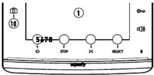
[1]. Selected the channel associated with the device that you want to control by pressing the SELECT button (8): the indicator light of the channel selected flashes (or the 4 indicator lights flash for channel 5).
Press the channel selection button as many times as necessary until the indicator lights show the required channel.
[2]. Control your equipment using the Open/On, STOP and Close/Off buttons on the monitor.
The equipment will react as stated in the table below:
| Equipment controlled | Press button: | ||
| Open/on (5) | STOP (6) | Close/off (7) | |
| Garage door Open Stopped (if the door is moving) Closed | |||
| Lighting On - Off | |||
| Roller shutter Open | • Stopped (if the roller shutter moving)• Favourite position (if the roller shutter is stopped) | Closed | |
| Gate Open Stopped (if the gate is moving) Closed | |||
8.5 Viewing / deleting photos
The monitor can store up to 100 photos in its internal memory: when the memory is full, the oldest photo is deleted and replaced by the new one.
For each call, the monitor saves a photo taken with the door station camera and the photo LED (10) comes on:
- If the call is not answered, the photo LED (10) remains lit to indicate that a new photo has been saved.
- If the calls is answered, the photo LED (10) goes out.
8.5.1 Viewing the photo(s)
Note: if the photo LED (10) is on, it goes out as soon as a photo is viewed.
For each photo, the sequence number and date and time it was taken are shown at the top of the screen.
To view the photos saved in the monitor's memory:
[1]. press one of the two settings buttons (16) briefly to see the last photo saved.
[2]. press one of the two settings buttons (16) briefly to browse the photos.
[3]. press the "Back" button (17) briefly to exit the photo viewer.
8.5.2 Deleting a photo
[1]. When you view a photo, press the "Menu" button (15) briefly: a deletion message appears on the screen.
[2]. Using the settings buttons (16), select "yes" to delete the photo or "no" to exit without deleting it: the parameter selected is displayed in red.
[3]. Press the "Menu" button (15) to confirm your choice.
8.5.3 Deleting all photos saved
To delete all photos, you must exit the photo viewer.
[1]. Press the "Menu" button (15).
[2]. Press the "Menu" briefly several times until you reach the "Delete all" tab.
[3]. Press one of the settings buttons (16) to confirm that all photos are to be deleted: the message "Deleting" is displayed.
[4]. Press the "Back" button (17) to exit.

text_image
Technical diagram with labeled components and numbered parts, including a valve, grid, and directional arrows9.1 Cleaning
The videophone should be cleaned using a soft, dry cloth; do not use solvents. Before cleaning, switch off the equipment.
10 - TECHNICAL DATA
| Monitor | ||
| Power supply Type | 100-240 V / 50-60 Hz mains adaptor, 0.5 A | Output: 17 Vdc, 1.1 A |
| Protection against inversion of polarity Yes | ||
| Screen 7” (17 cm) screen - Resolution: 800 x 480 pixels | ||
| Settings bell-tone volume, listening volume, brightness, contrast, colours, language, time, date, bell-tone | ||
| Image memory 100 photos on the internal memory | ||
| Mounting Wall mount | ||
| Dimensions (w x h x d) 225 x 155 x 22 mm | ||
| Operating temperature From -10°C to +55°C | ||
| Radio transmitter Frequency Range | 433.42 MHz < 10 mW 200 metres (free field) | |
| Door station | ||
| Camera Angle of vision: H: 95°/V: 67° | ||
| Night vision Infrared LEDs | ||
| Operating temperature From -20°C to +55°C | ||
| Outputs Latch: 12V, 800 mA | Dry contact | |
| Electric latch output activation time 2 seconds | ||
| Dry contact activation time 1 second | ||
| Name plate holder and call button | Back-lit call button for 1 residence or Back-lit call buttons for 2 residences | |
| Materials Aluminium and plastic | ||
| Mounting Surface mounting with rain shield | ||
| Dimensions (w x h x d) 76 x 148 x 45 mm | ||
| Settings Loud speaker volume | Call signal | |
INHOUDSOPGAVE
1 - WELKOM 2
1.1 Wie is Somfy ? 2
1.2 Assistentie 2
1.3 Garantie 2
2 - BELANGRIJKE INFORMATIE - VEILIGHEID 2
3 - PRODUCTBESCHRIJVING 3
3 - PRODUCTBESCHRIJVING
text_image
Diagram showing various electronic devices and components with numbered labels, including an open book, a circuit board, a screen, and a device labeled 'study'.natural_image
Diagram of a car above a vehicle with two circular components, no text or symbols presentnatural_image
Technical diagram showing screw assembly with exploded view of internal components (no text or labels)
natural_image
Pure electrical circuit lines without any symbols
text_image
Diagram showing a device connected to a battery, with an arrow indicating direction of connection or operation.natural_image
Two diagrams showing cable routing between a device with wires, no text or symbols presentNL
text_image
Technical diagram showing two views of a device with labeled ports and directional arrows indicating movement or assembly.natural_image
Top-down circular diagram with four concentric rings and a central dot, no text or symbols present.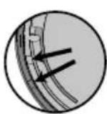


natural_image
Top-down schematic of a circular mechanical component with four concentric circular features (no text or symbols)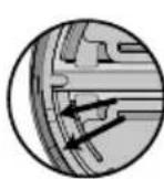


natural_image
Circular diagram with four concentric rings and four small circular elements, no text or symbols present.
natural_image
Three circular objects with different shading and label 'b c d', no text or symbols presentnatural_image
Circular diagram with two shaded segments and a central horizontal line, no text or symbols present.
text_image
b b c c d
natural_image
Diagram showing a circular mechanical component with four circular features, and three close-up views of the internal structure (no text or symbols)
natural_image
Simple line drawing of a washing machine with a circular component and a container (no text or symbols)text_image
Diagram illustrating the working principle of a washing machine, showing components like fan, washer, and water level with labeled parts.
text_image
SYMBOL SNFY
text_image
Superconductor M200V
text_image
Technical diagram with labeled components and numbered parts, including a magnifying glass and grid patterntext_image
Diagram showing a device panel with labeled components and an inset circular view highlighting internal components.7 - DRAADLOZE BEDIENING VAN SOMFY RTS SYSTEMEN
text_image
Diagram with labeled components and numbered annotations, including a bottle, grid, and numbered circles.9.1 Reinigen
text_image
Exploded view diagram of electronic devices with numbered labels indicating parts like screen, keyboard, and speaker.natural_image
Technical diagram showing assembly of screws into a device housing, with an inset close-up of the component detail (no text or symbols present)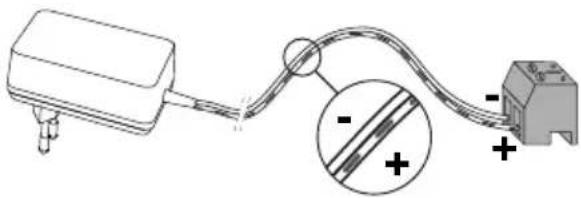
natural_image
Pure electrical circuit lines without any symbols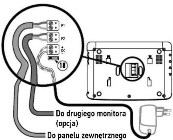
text_image
Diagram showing a device connected to a battery, with an arrow indicating direction of connection or operation.natural_image
Diagram showing two configurations of cable or wire connections with no visible text or symbolsPL
natural_image
Diagram showing a device with a cable inserted into a control panel, connected by a wire (no text or symbols present)
natural_image
Line drawing of a portable electronic device with a circular dial and a rotary knob, no text or symbols present.natural_image
Top-down circular diagram with four concentric rings and a central spiral, no text or symbols present.

natural_image
Top-down schematic of a circular mechanical component with four concentric circular features (no text or symbols)


natural_image
Circular diagram with two semicircular segments and a central horizontal line, no text or symbols present.
text_image
b b c c dtext_image
Diagram illustrating the working principle of a washing machine, showing components like fan, washer, and water level with labeled parts.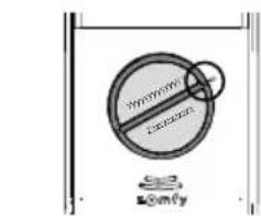
text_image
No Sign Somy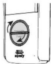
text_image
Technical diagram with labeled components and numbered parts, including a magnifying glass and grid pattern6.1.2 Zmiana melodii monitora
text_image
Diagram showing a device panel with labeled components and an inset circular view highlighting internal components.7 - STEROWANIE BEZPRZEWODOWE URZĄDZENIAMI SOMFY RTS
text_image
Diagram with labeled components and numbered annotations, including a bottle, grid, and circular elements9.1 Czyszczenie
text_image
Exploded view diagram of a smart home control panel with numbered parts including open book, connected circuit, display, and screen.natural_image
Illustration of a car on a road with two circular water tanks, no text or symbols presentnatural_image
Technical diagram showing assembly of screws into a device housing, with an inset close-up of the component detail (no text or symbols present)
natural_image
Simple line drawing of a device connected to a terminal block, with an inset showing a magnified view of the cable (no text or symbols)
text_image
Diagram showing a device connected to a battery, with an arrow indicating direction of connection or operation.natural_image
Two technical diagrams showing cable routing between a device with wires and connectors, no text or symbols present.CS
V300
text_image
Technical diagram showing two views of a remote control device with labeled buttons and directional arrows indicating movement.natural_image
Top-down circular diagram with four concentric rings and a central dot, no text or symbols present.


natural_image
Top-down schematic of a circular mechanical component with four concentric circular features (no text or symbols)


natural_image
Circular diagram with four concentric rings and four small circular elements, no text or symbols present.
natural_image
Three circular objects with different shading and label 'b c d', no text or symbols presentnatural_image
Circular diagram with two shaded segments and a central horizontal line, no text or symbols present.
text_image
b b c c d
natural_image
Diagram of a circular mechanical component with four circular features, shown in three progressive views (no text or symbols)
natural_image
Simple line drawing of a washing machine with a circular component and a container (no text or symbols)text_image
Diagram illustrating the working principle of a washing machine, showing components like fan, washer, and fan valve with directional arrows.
text_image
SYMBOL SNFY
text_image
Non-convexing @2017
text_image
Technical diagram with labeled components and numbered parts, including a container, grid, and directional arrowstext_image
Diagram showing a device panel with labeled buttons and a circular inset view highlighting two labeled components.7 - BEZDRÁTOVÝ OVLADAČ PRO ZAŘÍZENÍ SOMFY RTS
text_image
Diagram showing a device with 3s adjustment and a close-up of its internal components, likely illustrating a repair or cleaning process.
text_image
14 1stext_image
Diagram with labeled components and numbered annotations, including a magnifying glass and grid pattern2 Copyright © 2018 SOMFY ACTIVITES SA. All rights reserved.
text_image
Diagram showing labeled components of an electrical circuit: a lamp, open book, and connected plug with cable.

text_image
Illustration showing a set of black screw-like objects and a row of cylindrical objects, with the number 6 circled in a circle.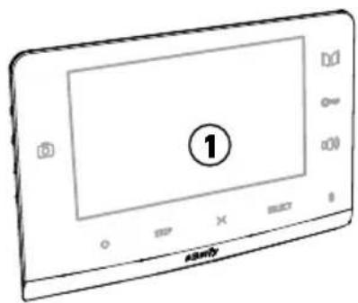
text_image
Technical diagram showing labeled parts of a device with numbered annotationstext_image
Diagram showing a door lock system with labeled components A, B, and a traffic light symbolnatural_image
Diagram of a car above a vehicle with two circular components, no text or symbols presentnatural_image
Technical diagram showing screw fasteners and a component assembly (no text or labels)natural_image
Pure electrical circuit lines without any symbolstext_image
Diagram showing a device connected to a battery with an arrow indicating direction of connection or operation.natural_image
Diagram showing two configurations of cable or cable penetration with a device, no text or symbols presentRU
V300
natural_image
Diagram of a device with a cable being inserted into a control panel (no text or symbols visible)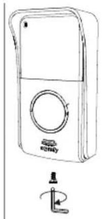
natural_image
Line drawing of a portable electronic device with a circular dial and a rotary knob, no text or symbols present.natural_image
Top-down circular diagram with four concentric rings and a central spiral, no text or symbols present.


natural_image
Top-down schematic of a circular mechanical component with four concentric circular features (no text or symbols)


text_image
Diagram of a circular mechanical component with labeled cross-sections and a prohibition symbol
text_image
Diagram illustrating the working principle of a washing machine, showing components like a circular fan and a washing bottle with brand mark 'KonoXX'.text_image
Diagram illustrating the working principle of a washing machine, showing components like inner casing, wheel, and fan with labeled parts.
text_image
Koroox S 100%
text_image
Gumfy
text_image
Diagram with labeled components and numbered circles, likely indicating parts of a device or layout.text_image
Diagram showing a device panel with labeled buttons and a circular inset showing two labeled components (8 and 7).text_image
Diagram with labeled components and numbered circles, likely indicating parts of a mechanical or electrical assembly.text_image
Technical diagram with labeled components and numbered annotationsت predicts tightness suggests a concept of the correct situation.
13
text_image
Diagram of a circular device with labeled components and prohibition symbol, including three cross-sectional views labeled b, c, and d.text_image
Technical diagram illustrating the working principle of a washing machine, showing components before and after assembly.natural_image
Diagram of a mechanical component with circular features and directional arrows indicating rotation or assembly (no text or symbols)text_image
Diagram showing a water level control valve with labeled components and directional arrows indicating flow or movement.
text_image
XXXXXX Lorry0-3 μ
natural_image
Simple line drawing of a container with a circular component and a small labeled component (no text or symbols)natural_image
Top-down schematic of a circular mechanical component with four concentric circular features (no text or symbols)natural_image
Top-down circular diagram with four concentric rings and a central circle, no text or symbols present.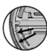

natural_image
Diagram showing two electronic devices connected by a cable, with no visible text or symbolsb
]7 . [ خدام
.torx مفتاح

natural_image
Line drawing of a portable electronic device with a circular button and a rotary knob (no text or symbols)natural_image
Two diagrams showing cable routing between a device and a connector, with no visible text or symbols.natural_image
Technical diagram showing screw fasteners and a component with an inset close-up view (no text or symbols)
natural_image
Pure electrical circuit lines without any symbols
natural_image
Diagram showing a device connected to an electrical outlet with a power plug (no text or symbols)ε-1 سکن
flowchart
graph LR
    A["Device"] --> B["Switch 1"]
    B --> C["Switch 2"]
    C --> D["Switch 3"]
    D --> E["Monitor with LCD screen"]
    E --> F["Plug connected to output"]
الوصف(shرحExplanation)
natural_image
Pure technical line drawing of a mechanical part with no text or symbols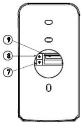
text_image
⑨ ⑧ ⑦ 0العربية

text_image
6-1 6-2 s@mfy
text_image
45148 76 30 3 70 2 ⑩وصفشرح علامة
text_image
Exploded view diagram of electronic devices with numbered labels indicating parts like reading, contacts, and screen displayكميةشرح علامة
| شرح علامة | |
| 1 | 1 |
| 2 | 2 |
| 3 | 3 |
| 4 | 4 |
| 5 | 5 |
| 6 | 6 |
| 7 | 7 |
| 8 | 8 |
| 9 | 9 |