
V350 - Video Intercom SOMFY - Free user manual and instructions
Find the device manual for free V350 SOMFY in PDF.
| Product type | Video intercom |
| Brand | Somfy |
| Model | V350 |
| Screen | Color 7 inches (17 cm), resolution 800 x 480 pixels |
| Monitor dimensions (W x H x D) | 220.5 x 175 x 24 mm |
| Street panel dimensions (W x H x D) | 77 x 151 x 45 mm |
| Monitor power supply | Power adapter 100-240 VAC, 50/60 Hz, output 24V 1A |
| Panel power supply | Via monitor (2-wire cable) |
| Night vision | Infrared LEDs |
| Camera viewing angle | Horizontal 102°, vertical 65° |
| Outputs | Electric strike 12V 800 mA max, dry contact for gate |
| Number of ringtones | 7 adjustable melodies |
| Photo memory | 100 photos, exportable via micro SD card (not included) |
| RTS radio transmitter | 5 channels, range 200 m in open field, frequency 433.42 MHz |
| Maximum number of monitors | 2 |
| Monitor operating temperature | -10°C to +55°C |
| Panel operating temperature | -20°C to +55°C |
| Panel protection rating | IP54 |
| Panel materials | Aluminum and plastic |
| Warranty | 5 years |
| Cleaning | Dry, soft cloth, no solvent, device powered off |
| Safety | Do not let children play, do not immerse, use only by capable persons |
Frequently Asked Questions - V350 SOMFY
User questions about V350 SOMFY
0 question about this device. Answer the ones you know or ask your own.
Ask a new question about this device
Download the instructions for your Video Intercom in PDF format for free! Find your manual V350 - SOMFY and take your electronic device back in hand. On this page are published all the documents necessary for the use of your device. V350 by SOMFY.
USER MANUAL V350 SOMFY
natural_image
Front view of a modern digital display device with control buttons (no visible text or symbols on screen)
natural_image
Exterior view of a modern silver remote control device (no visible text or symbols)1 - BIENVENUE 2
1.1 Qui est Somfy? 2
1.2 Assistance 2
1.3 Garantie 2
2 - INFORMATIONS IMPORTANTES - SÉCURITÉ ---- 2
Communication (activation micro)

natural_image
Pure electrical circuit lines without any symbols
natural_image
Diagram of a device with an arrow indicating direction, showing a component inserted into a housing (no text or symbols present)5 - INSTALLATION DE LA PLATINE DE RUE
natural_image
Technical line drawing of a device with circular components and directional arrows, no text or symbols presentnatural_image
Simple line drawing of a monitor connected to a power outlet (no text or symbols)6 - INTERFACE UTILISATEUR
natural_image
Grid of nine simple icons including boxes, books, a lightbulb, and a battery, arranged in two rows (no text or symbols)

flowchart
graph TD
    A["Start"] --> B["Test"]
    B --> C["Action Button"]
FR Visiophone V®350
natural_image
Black-and-white photo of a smiling man in a hoodie, displayed within a smartphone interface (no text or symbols on the image itself)natural_image
Black-and-white portrait of a smiling man in a hooded jacket, outdoors with blurred background (no text or symbols visible)natural_image
Black-and-white portrait of a smiling man in a hoodie, with blurred foliage background (no text or symbols)natural_image
Black-and-white photo of a smiling man in a hoodie, with blurred background and no visible text or symbols.natural_image
Black-and-white photo of a smiling man in a hooded jacket, outdoors with blurred background (no text or symbols visible)natural_image
Black-and-white photo of a smiling man in a hooded jacket, outdoors with blurred background (no text or symbols visible)natural_image
Black-and-white photo of a smiling man outdoors, with a coffee cup icon overlaid (no readable text or symbols)Réglage de l'heure

natural_image
Two small icons: a radio button with sound waves and a musical note, displayed in a UI panel (no text or symbols on icons)• Volume sonore de la communication.

• Volume sonore de la mélodie.


Choix de la mélodie

natural_image
Black-and-white photo of a sedan parked in front of a row of houses (no visible text or signage)natural_image
Black sedan parked in front of a residential house with visible windows and street lighting (no text or symbols)natural_image
Black sedan parked in a residential area with houses and a security symbol overlay (no readable text or symbols on the car or background)natural_image
Row of five icons: a box, a document, a warehouse, and a lightbulb, displayed on a white background with a right-side navigation bar (no text or symbols on icons)Transfert des photos

flowchart
graph LR
    A["Image"] --> B["File Icon"]
flowchart
graph TD
    A["Device 1"] --> B["Output Device"]
    C["Device 2"] --> B["Output Device"]
natural_image
Pure electrical circuit lines without any symbols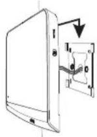
natural_image
Diagram of a device with an attached electrical socket and cable, showing no text or symbols5 - INSTALLATION DER AUSSENSTATION
natural_image
Two technical diagrams showing cable installation with connectors and wiring, no text or symbols presentnatural_image
Technical line drawing showing two mechanical components with internal connections and a directional arrow (no text or symbols)natural_image
Technical line drawing of a device with two views: one showing a circular dial and arrow, the other showing a multi-circular dial with arrows (no text or symbols)natural_image
Simple line drawing of a monitor connected to an electrical outlet (no text or symbols)
Ab


Bestätigen

natural_image
Grid of nine simple icons including boxes, storage, lightbulb, and power button (no text or labels)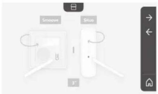

flowchart
graph TD
    A["Button"] --> B["Test"]
    B --> C["Arrow to Right"]
    B --> D["✓"]
    B --> E["×"]
    B --> F["←"]
natural_image
Black-and-white photo of a smiling man in a hoodie, displayed within a digital interface frame (no readable text or symbols)natural_image
Illustration of a mobile device interface with buttons and a blank screen (no readable text or symbols)natural_image
Front view of a mobile device interface with control buttons and a small display screen (no readable text or symbols)natural_image
Black-and-white portrait of a smiling man in a hooded jacket, outdoors with blurred background (no text or symbols visible)natural_image
Black-and-white portrait of a smiling man outdoors, wearing a hooded jacket (no text or symbols visible)natural_image
Black-and-white portrait of a smiling man outdoors, with blurred background and no visible text or symbolsnatural_image
Black-and-white photo of a smiling man in a hooded jacket, outdoors with blurred background (no text or symbols visible)natural_image
Black-and-white photo of a smiling man in a hooded jacket, outdoors with blurred background (no text or symbols visible)natural_image
Black-and-white photo of a smiling man with a coffee cup icon overlay (no readable text or symbols)natural_image
Two small icons: a radio with signal waves and a music note, displayed on a plain background (no text or symbols)
natural_image
Black-and-white photo of a sedan parked in front of a row of houses (no visible text or signage)natural_image
Black sedan parked in front of a row of houses with visible roof and street signage (no readable text or symbols)natural_image
Black sedan parked in a residential street with houses and pedestrians in the background (no visible text or symbols)natural_image
Row of five icons: a closed storage box, a warehouse with boxes, a house, and a lightbulb, displayed on a white background (no text or symbols)natural_image
Line drawing of a rectangular electronic device with a labeled component and an arrow pointing to it (no text or symbols beyond the label)natural_image
Pure electrical circuit lines without any symbols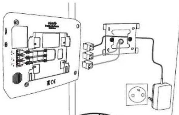
natural_image
Diagram of a device with an arrow indicating direction, showing internal components and a small component (no text or symbols)5 - INSTALLAZIONE DELLA PULSANTIERA ESTERNA
natural_image
Diagram showing two cable installation steps with exposed wires and connectors (no text or labels)
natural_image
Technical line drawing showing two views of a door lock mechanism with no text or symbolsnatural_image
Technical line drawing of a device with two views: one showing a circular dial and arrow, the other showing a rotary knob and three circular buttons (no text or symbols)natural_image
Simple line drawing of a monitor connected to an electrical outlet (no text or symbols)6 - INTERFACCIA UTENTE

natural_image
Grid of nine simple icons including boxes, books, a lightbulb, and power button, arranged in two rows (no text or symbols)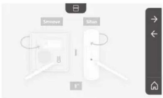
flowchart
graph TD
    A["Smooye"] --> B["3" Speed Indicator"]
    C["Situo"] --> B
    B --> D["Control Interface"]
flowchart
graph TD
    A["Button"] --> B["Test"]
    B --> C["Control Panel"]
    style A fill:#f9f,stroke:#333
    style B fill:#ccf,stroke:#333
natural_image
Black-and-white photo of a smiling man in a hooded jacket, displayed within a smartphone interface (no text or symbols on the image itself)natural_image
Illustration of a mobile device with a blank screen and control buttons (no text or symbols)natural_image
Front view of a mobile device interface with control buttons and a blank screen (no readable text or symbols)natural_image
Black-and-white portrait of a smiling man outdoors, wearing a jacket and dark jacket (no visible text or symbols)natural_image
Black-and-white portrait of a smiling man outdoors, wearing a hooded jacket (no text or symbols visible)natural_image
Black-and-white photo of a smiling man in a hoodie, with blurred background and no visible text or symbols.natural_image
Black-and-white photo of a smiling man in a hooded jacket, outdoors with blurred background (no text or symbols visible)natural_image
Black-and-white photo of a smiling man in a hoodie outdoors, with no visible text or symbols on the subject or background.natural_image
Simple line drawing of a landscape with a diagonal line crossing over it, next to a vertical toolbar with icons (no text or symbols on the landscape itself)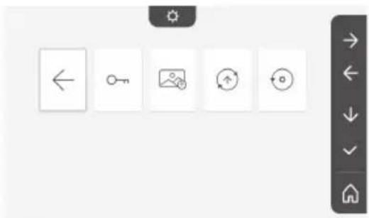
natural_image
Two small icons: a radio with signal waves and a music note, displayed on a plain background (no text or symbols)
natural_image
Black-and-white photo of a sedan parked in front of residential houses (no visible text or signage)natural_image
Black and white photo of a sedan parked in front of residential houses with a solar panel icon on the right (no visible text or symbols)natural_image
Black sedan parked in a residential area with houses and a security symbol overlay (no readable text or symbols on the car or background)natural_image
Row of five icons: storage box, warehouse, garage, and lightbulb, displayed in a row with a right-side menu bar on the right (no text or symbols on icons)flowchart
graph TD
    A["Device 1"] --> B["Output Device"]
    C["Device 2"] --> B["Output Device"]
natural_image
Pure electrical circuit lines without any symbols
natural_image
Electrical wiring diagram showing connections between an AC panel and a power outlet (no text or symbols present)

natural_image
Diagram of a device with an arrow pointing to a component, no text or symbols presentnatural_image
Diagram of cable routing through a device with connectors (no text or symbols)natural_image
Technical diagram of a mechanical assembly with labeled parts (no text or symbols present)[3]. Συνδέστε:
natural_image
Diagram of a mechanical device with rotating components and a base, showing no text or symbols.natural_image
Technical line drawing of a device with two views: one showing a circular dial and arrow, the other showing a multi-hole knob (no text or symbols)natural_image
Simple line drawing of a monitor connected to an electrical outlet (no text or symbols)natural_image
Grid of nine simple icons including boxes, books, lightbulb, power button, open book, storage box, and smart cube (no text or symbols)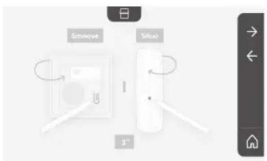
flowchart
graph TD
    A["Sinoove"] --> B["I"]
    C["Sitoao"] --> B["I"]
    B --> D["3^-"]

flowchart
graph TD
    A["Text"] --> B["Button"]
    style A fill:#f9f,stroke:#333
    style B fill:#bbf,stroke:#333
natural_image
Black-and-white photo of a smiling man in a hoodie, displayed within a mobile device interface (no readable text or symbols)natural_image
Illustration of a generic electronic device with control buttons and a small screen (no text or symbols)natural_image
Black-and-white portrait of a smiling man outdoors, wearing a hooded jacket (no visible text or symbols)natural_image
Black-and-white portrait of a smiling man outdoors, wearing a hooded jacket (no text or symbols visible)natural_image
Black-and-white photo of a smiling man in a hooded jacket, with blurred background and no visible text or symbols.natural_image
Black-and-white photo of a smiling man in a hoodie, with blurred background and no visible text or symbols.natural_image
Black-and-white photo of a smiling man in a hooded jacket, with blurred background foliage and no visible text or symbols.natural_image
Simple line icon of a person crossing a diagonal line, no text or symbols present
Ρύθμιση της ώρας

natural_image
Two small icons: a radio with signal waves and a music note, displayed on a plain background (no text or symbols)
natural_image
Black-and-white photo of a sedan parked in front of a row of houses (no visible text or signage)natural_image
Black and white photo of a sedan parked in front of residential houses with a sun icon on the left (no visible text or symbols)natural_image
Black and white photo of a car parked in front of residential houses (no visible text or symbols)natural_image
Row of five icons: storage box, warehouse, lightbulb, and document icon (no text or symbols)natural_image
Line drawing of a rectangular electronic device with a label pointing to its side (no text or symbols on the device itself)natural_image
Pure electrical circuit lines without any symbols
natural_image
Diagram of a device with an arrow indicating direction, showing internal components and a small inset component (no text or symbols)natural_image
Technical line drawing of a device with two views: one showing a circular dial indicator and arrow, the other showing a multi-hole rotary knob (no text or symbols)natural_image
Simple line drawing of a monitor connected to an electrical outlet (no text or symbols)6 - INTERFAZ DE USUARIO
Ajuste de la fecha:
Día/Mes/Año
Ajuste del reloj:
natural_image
Grid of nine icons including boxes, books, a lightbulb, and a battery with power button, displayed in a software interface (no text or symbols on icons)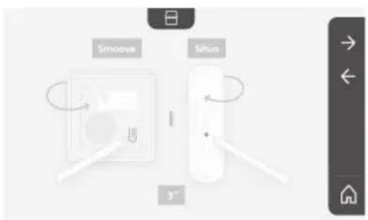
natural_image
Black-and-white photo of a smiling man in a hoodie, displayed within a smartphone interface (no text or symbols on the image itself)natural_image
Illustration of a mobile device with a blank screen and control buttons (no text or symbols)natural_image
Black-and-white portrait of a smiling man with a beard, wearing a hooded jacket, outdoors with blurred foliage background (no text or symbols visible)natural_image
Black-and-white portrait of a smiling man outdoors, wearing a hooded jacket (no text or symbols visible)natural_image
Black-and-white portrait of a smiling man with a mustache, wearing a hooded jacket, outdoors with blurred foliage background (no text or symbols visible)
natural_image
Black-and-white photo of a smiling man in a hooded jacket, outdoors with blurred background (no text or symbols visible)natural_image
Black-and-white photo of a smiling man in a hooded jacket, with blurred background foliage and no visible text or symbols.natural_image
Simple line drawing of a landscape with a diagonal line crossing over it, next to a vertical toolbar with icons (no text or symbols on the landscape itself)Ajuste de la hora

Ajuste del reloj:
natural_image
Two small icons: a radio with signal waves and a musical note, displayed on a plain background (no text or symbols)
natural_image
Black-and-white photo of a sedan parked in front of residential houses (no visible text or signage)natural_image
Black and white photo of a sedan parked in front of a row of houses with a sun icon on the left side (no visible text or symbols)Ajuste del color

natural_image
Black sedan parked in a residential area with houses and a fence in the background (no visible text or symbols)natural_image
Row of five icons: storage box, warehouse, garage, lightbulb, and home (no text or symbols)Traspaso de fotos

--- corrente contínua
\~ corrente alternada
natural_image
Pure electrical circuit lines without any symbols


natural_image
Diagram of a device with an arrow pointing to a component, no text or symbols presentnatural_image
Diagram showing two views of a device with circular components and directional arrows, no text or symbols present.natural_image
Simple line drawing of a monitor connected to an electrical outlet (no text or symbols)6 - INTERFACE UTILIZADOR

Regulação
seguinte


Descer

Validação

Acerto da data:
Dia/Mês/Ano
Acerto do relógio:
natural_image
Grid of nine icons including boxes, books, lights, and a power button, displayed in a software interface (no text or symbols on icons)
natural_image
Black-and-white photo of a smiling man in a hoodie, displayed within a smartphone interface (no readable text or symbols)natural_image
Black-and-white portrait of a smiling man outdoors, wearing a hooded jacket (no visible text or symbols)natural_image
Black-and-white portrait of a smiling man outdoors, wearing a hooded jacket (no text or symbols visible)natural_image
Black-and-white photo of a smiling man in a hoodie, with blurred background and no visible text or symbols.natural_image
Black-and-white photo of a smiling man in a jacket, with blurred background and no visible text or symbols.natural_image
Black-and-white photo of a smiling man in a hooded jacket, outdoors with blurred background (no text or symbols visible)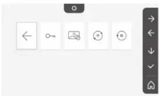
natural_image
Toolbar with five icons: left-pointing arrow, key, map, refresh, and circular icon (no text or labels)Acerto da hora

Acerto do relógio:
natural_image
Two small icons: a radio with signal waves and a musical note, displayed on a plain background (no text or symbols)
Seleção da melodia

natural_image
Black-and-white photo of a sedan parked in front of a row of houses (no visible text or signage)natural_image
Black sedan parked in a residential area with houses and a street lamp (no visible text or symbols)Regulação da cor

natural_image
Black sedan parked in a residential area with houses and pedestrians in the background (no visible text or symbols)natural_image
Row of five icons: a box, a storage unit, a house, and a lightbulb, displayed in a row with a right-side navigation bar on the right (no text or symbols on icons)natural_image
Line drawing of a rectangular electronic device with a label 'senny' and an arrow pointing to its side (no other text or symbols)1.1 Who are Somfy? 2
1.2 Assistance 2
1.3 Warranty 2
2 - IMPORTANT SAFETY INFORMATION 2
2.1 General information 2
2.2 General safety advice 2
2.3 Operating conditions 2
2.4 Recycling and disposal 2
2.5 Meaning of logos on the mains adaptor 2
3 - PRODUCT PRESENTATION 3
3.1 Composition of the kit 3
3.2 Product description 3
3.3 Standard installation 6
4 - INSTALLING THE MONITOR----7
5 - INSTALLING THE DOOR STATION 8
5.1 Fastening and wiring the door station 8
5.2 Connecting the door station 9
5.3 Fitting the name tag 9
5.4 Switching the installation on 10
6 - USER INTERFACE 10
6.1 The video entry phone 10
Setting the date: 11
Setting the clock: 11
Choice of ring tone melody: 11
Setting the ring tone volume: 11
Adding Somfy RTS equipment 12
Setting the time 17
Setting the date 17
Adjusting the volume 17
Choice of ring tone 18
Setting the contrast 18
Setting the brightness 18
Setting the colour 18
Memorising a group of RTS products 18
Deleting an RTS product 19
Setting the electric latch activation time 20
Transferring photos 21
Software update 21
Resetting the parameters 21
6.2 Door station settings 22
7 - MAINTENANCE 22
7.1 Cleaning 22
8 - TECHNICAL DATA 23
Thank you for choosing a Somfy product.
1.1 About Somfy
Somfy develops, manufactures and sells motors and automated systems for domestic equipment. These include motorisations for gates, garage doors or roller shutters, alarm systems, lighting controls and heating thermostats. All Somfy products are designed to meet your expectations in terms of safety, comfort and energy efficiency.
At Somfy, the pursuit of quality is a continuous process of improvement. Somfy's reputation has been built upon the reliability of its products, and the Somfy brand is synonymous with innovation and technological expertise worldwide.
1.2 Assistance
For more information on how to choose, purchase or install Somfy products, please contact either your retailer or Somfy.
1.3 Warranty
This product is guaranteed for 5 years from the date of purchase. The general warranty conditions are available at: www.somfy.fr
2 - IMPORTANT INFORMATION - SAFETY
2.1 General information
Read these installation guide and safety instructions carefully before installing this Somfy product. Follow all of the instructions carefully and keep them for the lifetime of the product.
Before installing, check that this Somfy product is compatible with the associated equipment and accessories.
These instructions describe how to install and use this product.
Any installation or use outside the field of application specified by Somfy is non-compliant. This invalidates the Somfy warranty and discharges Somfy of all liability, as does any failure to comply with the instructions provided herein.
Somfy cannot be held responsible for changes to norms or standards occurring after the publication of this guide.
Somfy declares that the product described in these instructions, when used in accordance with these instructions, complies with the essential requirements of the applicable European Directives and, in particular, with the Radio Directive 2014/53/EU. The full text of the CE conformity declaration can be found at the following Internet address: www.somfy.com/ce.
Non-contractual images.
2.2 General safety instructions
Do not let children play with the control point. Never immerse the control point in liquid.
This product is not designed to be used by persons (including children) with reduced physical, sensory or mental capacities, or persons lacking in experience or knowledge, unless a person responsible for their safety is supervising them or has provided prior instructions regarding the use of this product.
2.3 Conditions for use
The radio range is limited by radio appliance control standards.
The radio range is heavily dependent on the environment in which it is used: interference may be caused by having large-scale electrical equipment near the installation, or by the type of material used in the site walls and partitions.
The use of a radio appliances (e.g. a set of Hi-Fi radio headphones) operating on the same radio frequency might be detrimental to the product's performance.
The purpose of this video entry phone camera is to identify a visitor; under no circumstances should it be used to monitor the street.
2.4 Recycling and disposal
Do not dispose of the product with household waste at the end of its life. Return the product to its distributor or use your local authority's special waste collection services.
2.5 Meaning of logos on the mains adapter

the mains adapter supplied with the product should only be used in a dry, sheltered place.

the mains adapter supplied with the product is a double-insulating type and therefore does not need to be connected to the earth conductor.

direct current

alternating
current
3.1 Composition of the kit
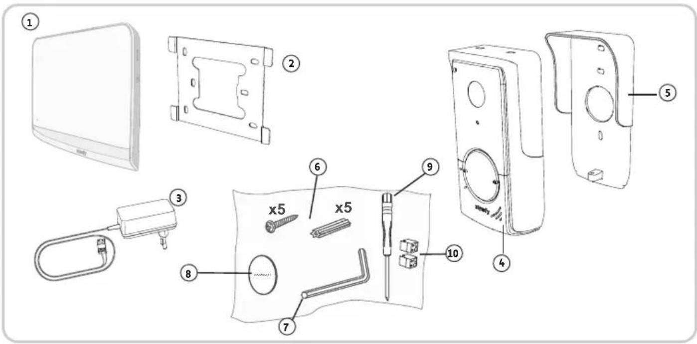
| No. Designation Quantity | ||
| 1 Indoor monitor 1 | ||
| 2 Monitor mounting bracket 1 | ||
| 3 Monitor mains adaptor 1 | ||
| 4 Door station 1 | ||
| 5 Rain shield 1 | ||
| 6 Screws + plugs for mounting the monitor and door station 5 + 5 | ||
| 7 Tamper-proof torx key 1 | ||
| 8 Additional name plate label 1 | ||
| 9 Flat-blade screwdriver 1 | ||
| 10 Connectors | 2 |
3.2 Product description
The video entry phone comprises an indoor monitor and a door station. The indoor monitor is connected to the door station using 2 wires. The door station can then be connected to a gate motorisation or to an electric latch/lock, 12 V AC or DC - 800 A max. This allows the video entry phone to be used to open a small or large gate.
The indoor monitor is also fitted with an RTS (Radio Technology Somfy) radio transmitter. This wireless control is used to operate a garage door, lighting, roller shutters or a Somfy gate (if within range of the monitor).
3.2.1 Monitor
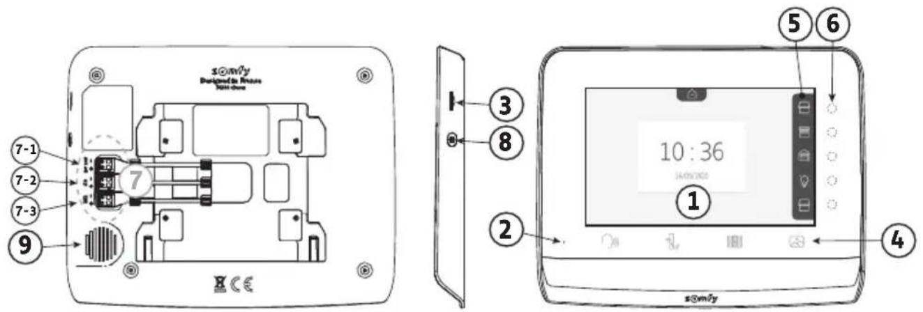
No. Designation Description
1 Screen Allows the user to see the visitor, consult the photos of missed visits, view the settings, etc.
2 Microphone Enables you to talk with the person at the door station.
3 SD micro card reader Allows photos stored in the internal memory to be exported. Note: SD micro card not supplied (max. 32 GB).
4 "Activation" buttons

Communication (microphone activation)

Electric latch/lock

Gate

Photo library
5 Visualisation pane Allows the user to visualise possible actions using the touch-sensitive keys to the right of the pane.
6 Indicator lights and touch-sensitive keys 5 indicator lights with touch-sensitive keys for the 5 control/navigation channels.
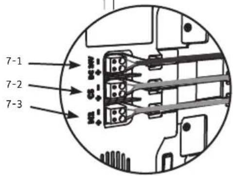
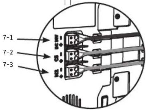
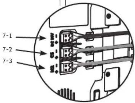
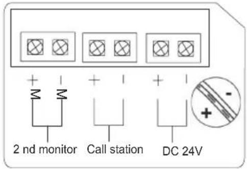
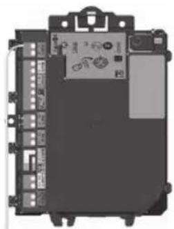
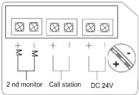
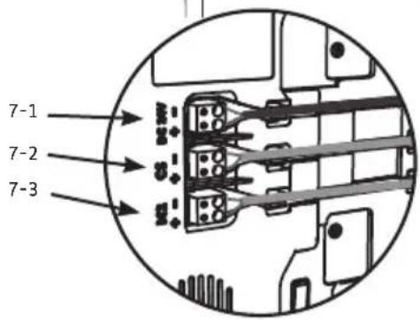
7 Terminal block 7-1 : connection to the mains adaptor. 2-2 : connection to the door station. 7-3 : connection to a second monitor (optional).
8 Button Settings access button
9 Speaker Enables the visitor to be heard in front of the door station.
3.2.2 Door station
The door station can be connected to a gate motorisation and an electric latch/lock (12 V AC/DC - 800 mA maximum).
The gate motorisation and latch/lock can be activated via the video entry phone monitor.
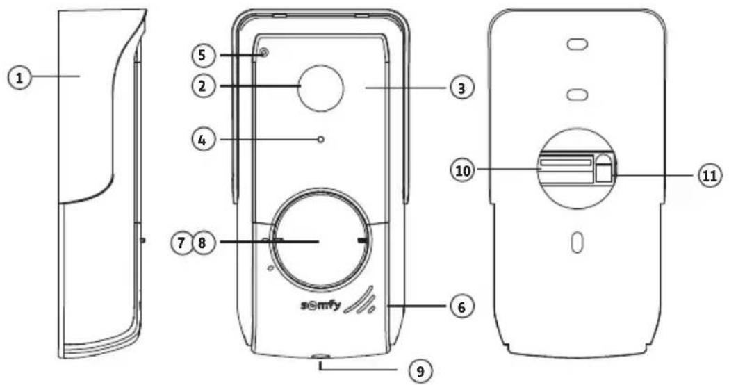
No. Designation Description
| 1 Rain shield | Protects the camera from the rain. | |
| 2 Camera Films | visitors and sends the image to the monitor. | |
| 3 Infrared LEDs | Provide enhanced night vision. | |
| 4 Brightness sensor | Automatically activates the infrared LEDs when it is dark. | |
| 5 Microphone | Enables visitors to talk to the person or | people inside. |
| 6 Speaker Enables | visitors to hear the person or people inside. | |
| 7 Back-lit name tag | Indicates your name on a label. | |
| 8 Back-lit call | button Enables visitors to trigger the monitor's ring tone. The camera and the monitor screen are switched on. | |
| 9 Anti-tamper screw | Prevents the door station from being opened without the tamper-proof torx key. | |
| 10 | Terminal block | Connects the monitor station to a gate motorisation or an electric latch/lock. |
| 11 | Speaker volume adjustment button | This is used to adjust the volume of the door station speaker. |


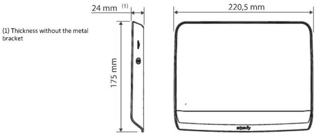
(thickness with rain shield)
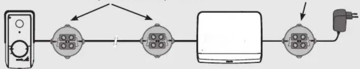
3.3 Standard installation

Note: If you need to use junction boxes to cable the video entry phone, do not use more than two boxes between the station and the monitor, or more than one box between the monitor and the power plug.
Max. 2 junction boxes Max. 1 junction box
flowchart
graph LR
    A["Remote Control Unit"] --> B["Switch 1"]
    B --> C["Switch 2"]
    C --> D["Laptop"]
    D --> E["Power Supply"]
    B -->|I| C
4 - INSTALLING THE MONITOR

NB
If you wish to control your Somfy RTS gate motorisation remotely via the monitor, you must save the radio control before the final monitor installation procedure (the monitor must be brought to the gate motorisation while powered via its mains adapter) or activate the button on the gate motorisation, depending on the motorisation models.
See section 7.3 Programming a Somfy RTS gate motorisation.
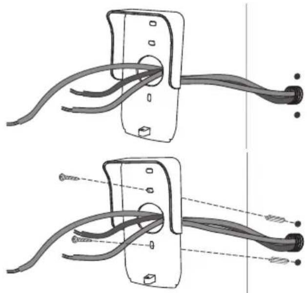
[1]. Fix the monitor mounting plate to the wall.
Important: The monitor mounting brackets must come out towards you.
Note: All the wires must pass inside the mounting bracket so they can be connected to the monitor.

[2]. Connect the mains adapter connector at the rear of the monitor to terminal block 7-1 in the direction indicated in the illustration (screws towards the right); the direction in which the wires are connected to the power pack is important.
Important: It is essential to use the mains adaptor provided to power the monitor.
Important: Do not connect the power plug to a socket when all the wiring is not terminated (door station, additional monitor).

natural_image
Pure electrical circuit lines without any symbols[3]. Connect the second connector supplied to terminal block 7-2. The corresponding cable shall be connected to the door station. Optional: Connect a third connector to the terminal block 7-3. The corresponding cable shall be connected to a second monitor (see the additional monitor's instructions).
Note: Place the wires in their intended locations to prevent any risk of them being pulled out.
Note: Identify the wires used for terminal blocks 7-2 and 7-3 in order to correctly wire the door station and the additional monitor (optional).


[4]. Clip the monitor to the mounting support, sliding it gently downwards until the support brackets are well inserted into the monitor's slots.

natural_image
Diagram of a device with an arrow indicating direction, showing internal components and a small inset panel (no text or symbols)5 - INSTALLING THE DOOR STATION
Avoid installing the camera facing a light source, as images of visitors may be impaired. We recommend that you install the door station at a height of approximately 1.60 m.
5.1 Fastening and wiring the door station
[1]. Route all the cables into the rain shield.
[2]. Fix the rain shield to the wall/pillar.
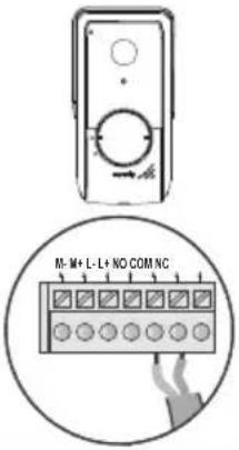
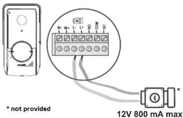
[3]. Connect:
- the monitor cable to the first 2 terminals on the door station:
M+ on the monitor to M+ on the door station
M- on the monitor to M- on the door station - the electric latch/lock cable to terminals L+ and L-on the door station.
- the motorisation cable to the dry contact output (COM and NO) on the door station
Note: To feed the cables into the terminals, use a screwdriver to press on the square with the notch, feed the wires in, then release.
[4]. Position the door station in the rain shield.
[5]. Screw the door station to the rain shield using the tamper-proof torx key provided.
natural_image
Diagram showing two cable installation steps with wires and connectors (no text or symbols)

natural_image
Technical line drawing showing two views of a door lock mechanism with no text or symbols5.2 Connecting the door station
5.2.1 Connecting to a Somfy gate motorisation
Note: When the motorisation is solar-powered, the wired controls are deactivated. In this case, you must use the monitor's wireless control to control your gate motorisation (see page 12).
[1]. Disconnect the motor from the mains power supply.
[2]. Remove the cover from the control cabinet or from the motor containing the electronics.
[3]. Connect the door station dry contact output (COM and NO) to the motorisation electronics. It is best to consult the gate motorisation instructions to connect the door station to the key contact input on the motorisation.
 | Somfy motorisations electronics | ||
 |  |  | |
| Connect... to the START terminals to the BUS terminals to the numbered terminals | |||
| COM 5 | 3 | 3 | |
| NO | 6 | 4 | 5 (for complete opening) or 6 (for pedestrian opening) |
Note: To connect the door station to another gate motorisation model, please refer to the installation instructions for that motorisation.
5.2.2 Connecting to an electric latch/lock
Connect the door station output to the latch/lock in accordance with the diagram opposite.
Observe the +/- polarity if indicated in the latch/lock instructions.
5.3 Fitting the name tag
[1]. Turn the call button anticlockwise to the engraved marking then remove.
[2]. Remove the round to access the name plate label.
[3]. Write your name on the white label using a permanent marker, then refit the label and its cove in the housing.
[4]. Reassemble the call button on the door station using the marks, and then turn clockwise until it locks.

natural_image
Technical line drawing of a device with circular components and directional arrows, no text or symbols present5.4 Powering on the installation
Once installation is complete, reconnect the gate motorisation to the power supply.
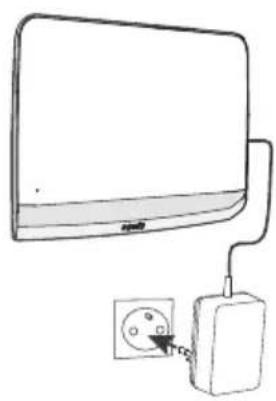
Then connect the mains adaptor provided to an electrical socket.
Important: The mains adaptor must be installed close to the monitor and must be easily accessible.
natural_image
Simple line drawing of a computer monitor connected to an electrical outlet (no text or symbols)6 - USER INTERFACE
The V®350 video entry phone brings together two worlds: on the one hand the video entry phone world, and on the other that of Somfy RTS home wireless control equipment.
The first world is based on functions such as:
- communication between the door station and the monitor,
- consultation, deletion and export of photos,
- opening the electric latch/lock and the gate,
- the settings (e.g.: contrast, brightness, ringtone, etc.).
The second world is that of the Somfy RTS home equipment wireless control (e.g.: roller shutters, lights, garage door, etc.).
6.1 The video entry phone
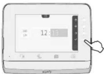
6.1.1 Start screen and basic settings
When switching on for the first time, the screen displays the Somfy logo for a few seconds before opening the basic settings.
Each step must then be validated to move onto the next step and access the start screen.
Note: in the event of a power cut, these settings remain in the monitor's memory.

To select a function, press the LED to the right of the pictogram displayed on the screen, for example:

Up
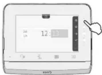

Next setting

Down


Confirmation

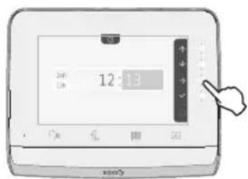
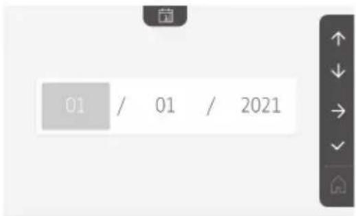
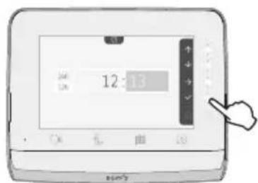
Setting the date:
Day / Month / Year
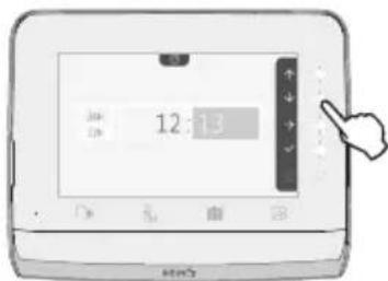
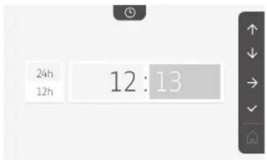
Setting the clock:
- 12- or 24-hour format
- Hour
- Minutes
- am / pm (if the 12-hour format is selected)
Choice of ring tone melody:
7 melodies are available
Setting the ring tone volume:
The validation screen is displayed. Select the house symbol to return to the start screen.
Start screen, on RTS equipment programmed.

6.1.2 Controlling Somfy RTS wireless equipment
The monitor is equipped with a Somfy Radio Technology (RTS) transmitter. It is only compatible with devices equipped with Somfy Radio Technology (RTS).
It is used to control the following Somfy devices, individually or simultaneously:
- garage door motorisation,
- lighting receiver,
- roller shutter motorisation,
- gate motorisation.
-etc.
This function is enabled thanks to a radio channel system identified by pictograms (see "Adding Somfy RTS equipment"). Each channel corresponds to an individual remote control and can be used to control one or more device(s). There is no limit to the number of devices that can be controlled by a single channel. To control a channel, you just need to press on it.
Important: Check that the device to be controlled is wireless and within the radio range of the monitor.
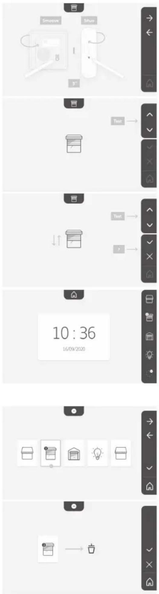
Adding Somfy RTS equipment
Press on the touch-sensitive key corresponding to the location of the first piece of equipment to be memorised.
Unless otherwise indicated, each step must then be validated to move on to the next step.
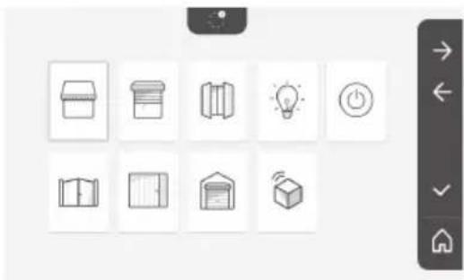
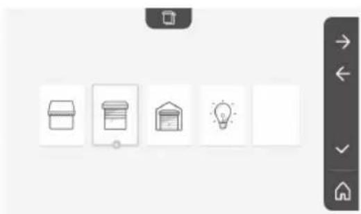
Select the pictogram which represents the product to be memorised:
| [6D24]Awning Rollershutter |  |  Hingedshutter Hingedshutter |  LightingON/OFF LightingON/OFF |  SocketON/OFF SocketON/OFF |
| Hingedgate | Sliding gate | Garagedoor | Other RTSproduct |
Press the PROG button of an RTS transmitter already paired with this product for 3 seconds: the product should react. Refer to the product instructions if it is a gate or garage door motorisation.
Press the touch-sensitive key corresponding to the arrow to pair the monitor with the product and move on to the next step.
Press the touch-sensitive key corresponding to the ← arrow to go back.
Press the touch-sensitive keys corresponding to the commands ↑ and ↓ and check the behaviour of the paired product.

natural_image
Grid of nine simple icons including open book, storage box, lightbulb, and power button (no text or symbols)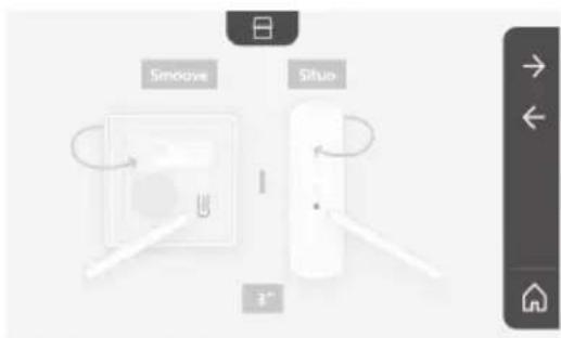

EN V®350 video entry phone
If the product in question reacts correctly, press the touch-sensitive key corresponding to validate √
If the product in question does not react correctly, press the touch-sensitive key corresponding to do not validate ✗ to begin the previous steps again.
If you press on the paired product is displayed on the right of the start screen.
Repeat as many times as necessary to pair all RTS products on the V*350 monitor.

6.1.3 Responding to a visitor
The pictogram flashes, the ring tone sounds and the screen below is displayed when a visitor presses the call button on the door station:

natural_image
Black-and-white photo of a smiling man in a hoodie, displayed within a smartphone screen (no text or symbols visible)Note: if the occupant does not answer the call, the monitor records a photo of the visitor before terminating the ring tone.
To take the call, press the "communication" pictogram:

The pictogram remains lit throughout the call. To end the communication, click on it again, open the gate or activate the electric lock.
Note: if no action is taken, the maximum duration of the communication is 2 minutes.
The internal monitor's microphone and the door station's speaker are only activated once the call has been accepted. During the call, it is possible to:
- open the gate by pressing a few seconds:

. This action will terminate the communication. The following screen will be displayed for

natural_image
Illustration of a tablet device with a blank screen and control buttons (no text or symbols)- open the electric latch/lock by pressing displayed for a few seconds:

. This action will terminate the communication. The following screen will be
- take a photo of the visitor by pressing the touch-sensitive key corresponding to the camera on the right of the screen. This photo is stored in the monitor's memory. The following screen will be displayed for a few seconds:

natural_image
Black-and-white portrait of a smiling man outdoors, wearing a hooded jacket (no visible text or symbols)- control Somfy RTS equipment (lighting in the alley, garage door, etc.): click on touch-sensitive key corresponding to the arrow, the following screen is displayed:

natural_image
Black-and-white portrait of a smiling man outdoors, wearing a hooded jacket (no text or symbols visible)Note: the pane on the right displays the RTS products that have been paired with the monitor.
EN V®350 video entry phone
Select the equipment by clicking on the touch-sensitive key to the right of the corresponding pictogram:

natural_image
Black-and-white photo of a smiling man in a hoodie, with blurred background and no visible text or symbols.Select the action to be carried our (open/close, up/down or on/off) or click on the touch-sensitive key beside the → arrow to return to the list of RTS products.
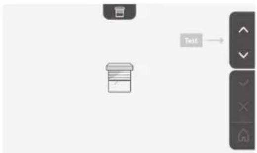
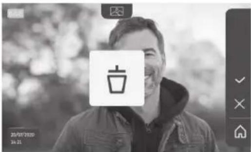
6.1.4 Stored photos of visitors
To consult the photos stored in the memory, regardless of whether they were taken manually or during your absence, press the pictogram: the following screen appears:

natural_image
Black-and-white photo of a smiling man in a hoodie, with blurred background and no visible text or symbols.Note: in the yellow zone at the top left, X/XX indicates the number of the new photo and the number of photos not yet viewed. The blue zone at the bottom left indicates the date and time of the photo displayed.
All photos not consulted are surrounded by a yellow box.
Via this screen, it is possible to:
- move to the following photo by pressing the touch-sensitive key corresponding to the ↓ arrow:

natural_image
Black-and-white photo of a smiling man in a hooded jacket, outdoors with blurred background (no text or symbols visible)Note: after beginning to scroll through the photos, the ↑ arrow enables you to access the previous photo and the ↓ arrow provides access to the next photo.
- delete the photo displayed by pressing the touch-sensitive key corresponding to the dustbin
Note: press the touch-sensitive key to finalise the action.
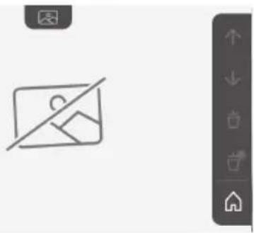
- delete all photos by pressing the pressing the touch-sensitive key corresponding to 📄, the following screen is displayed:

Note: press the √ touch-sensitive key to finalise the action, the following screen is displayed:
natural_image
Simple line icon of a photo frame with a diagonal line crossing over it, next to a vertical navigation bar (no text or symbols)Note: press the touch-sensitive key to return to the start screen.
6.1.5 Subsequent settings
To change the initial settings or configure additional settings, press the yellow button on the right-hand side of the monitor:
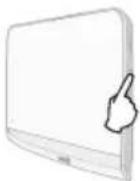
The first setting selection screen is displayed:
| (T44C)Time Date Volume Melody Contrast | (5861) | (2707) | (4409) | (3544) |
| (287C)Brightness Colour Memorise a group of RTS products | (4270) | (H223) | (H542)Delete an RTS product | (5477)Following settings |
The following settings are:
| Previous settings | Transfer photos | Reset the parameters |


natural_image
User interface toolbar with five function icons (left, key, photo, refresh, download) and a navigation button (no text or symbols on icons)Setting the time

Setting the clock:
- 12- or 24-hour format
• Hour - Minutes
- am / pm (if the 12-hour format is selected)
Setting the date

Setting the date:
Day / Month / Year
Adjusting the volume

It is possible to adjust the volume of the communication and the ring tone melody:
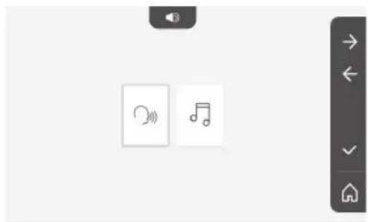
• Volume of the communication.

- Volume of the ring tone.


Choice of ring tone

7 melodies are available.

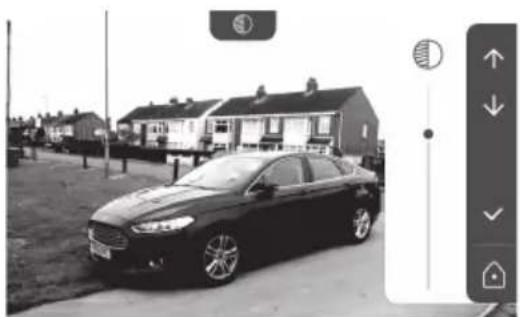
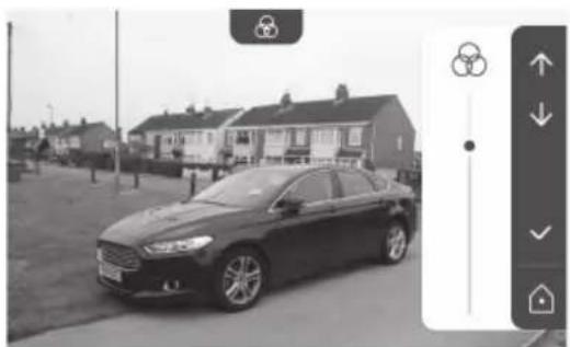
Setting the contrast

During this process, the door station camera is activated.
natural_image
Black-and-white photo of a sedan parked in front of a row of houses (no visible text or signage)Setting the brightness

During this process, the door station camera is activated.

natural_image
Black and white photo of a sedan parked in front of residential houses with a solar panel icon on the right (no visible text or symbols)Setting the colour
During this process, the door station camera is activated.
natural_image
Black sedan parked in a residential area with houses and a person walking nearby (no visible text or symbols)Memorising a group of RTS products

It is possible to add products similar to those already paired, for example a second roller shutter, on the same channel for grouped control.
Select the channel on which you wish to add an RTS appliance and validate.
natural_image
Row of five icons: storage box, tablet, warehouse, lightbulb, and home (no text or symbols)EN V®350 video entry phone
Press the PROG button of an RTS transmitter already paired with the product to be added for 3 seconds:
Press the touch-sensitive key corresponding to the arrow to pair the monitor with the product and move on to the next step.
Press the touch-sensitive key corresponding to the ← arrow to go back.
Press the touch-sensitive keys corresponding to the commands ↑ and ↓ and check the behaviour corresponding to the paired product.
If the product in question reacts correctly, press the touch-sensitive key corresponding to validate √
If the product in question does not react correctly, press the touch-sensitive key corresponding to do not validate to begin the previous steps again.
If you have pressed on, the start screen is displayed and the group to which the product has been added indicates the number of paired products.
Deleting an RTS product

It is possible to delete a product or group of products.
Note: if you wish to delete a product in a group, you must delete the group then pair the product or products again that you wish to control via the monitor.
Select the channel from which you wish to delete the RTS product or group of RTS products and validate.
Press the PROG button of an RTS transmitter already paired with the product to be deleted for 3 seconds:
Press the touch-sensitive key corresponding to the arrow to delete the pairing with the monitor and move on to the next step.
Press the touch-sensitive key corresponding to the ← arrow to go back.
Check that the product or products have been deleted.
If the equipment no longer reacts, press the touch-sensitive key corresponding to validate √
If the equipment reacts to the command, press the touch-sensitive key corresponding to do not validate to begin the previous steps again.
The product or group of products has been deleted.
The product or group of products no longer appears on the start screen.
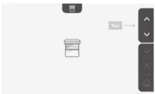
Setting the electric latch activation time

It is possible to set the activation time for the electric latch to 2, 5 or 10 seconds (default setting is 2 seconds).

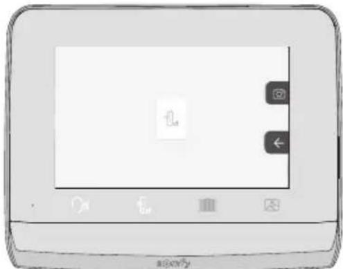
Transferring photos

The transfer operation is only possible if an SD micro card (max. 32 GB) has first been installed.

natural_image
Line drawing of a rectangular electronic device with a label pointing to its side (no text or symbols on the device itself)Press the touch-sensitive key corresponding to validate √
When "100%" is displayed in the yellow zone at the bottom of the screen, the transfer is complete.
Press the touch-sensitive key corresponding to 📧 to return to the settings screen or the key corresponding to 📨 to return to the start screen.
Note: the photos are not deleted from the monitor. To delete the photos, see "6.1.4 Stored photos of visitors".

flowchart
graph LR
    A["Image"] --> B["File"]
    style A fill:#f9f,stroke:#333
    style B fill:#bbf,stroke:#333
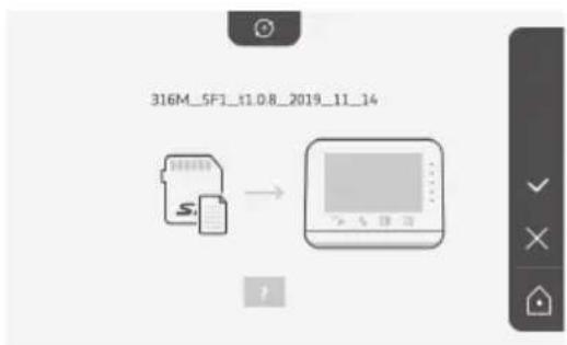
Software update

The screen displays the current software version.
To update the monitor software (firmware), you must first retrieve the latest version from our website and copy it onto an SD micro card, for example:
316M_SF1_t1.0.8_2019_11_14
Create a directory on the SD micro card named "update" and save the new firmware to this directory.
Insert the SD micro card in the monitor then validate the action.
Note: the parameters return to the "factory" settings and the photos and RTS equipment are conserved.
Resetting the parameters

This action deletes all personalised settings.
To be able to reuse the video entry phone, you must reconfigure the basic settings (date, time, ring tone melody, ring tone volume).
Note: the parameters return to the "factory" settings and the photos and RTS equipment are conserved.

flowchart
graph TD
    A["Device 1"] --> B["Output Device"]
    C["Device 2"] --> B["Output Device"]
6.2 Door station settings
6.2.1 Setting the speaker volume
To adjust the door station speaker volume, use the screwdriver supplied to turn the button on the back of the door station:
- clockwise to increase the volume.
- anti-clockwise to reduce the volume.
6.2.2 Activating or deactivating the audible beep of the call button:
An audible beep sounds when the call button is pressed. To deactivate or reactivate this beep, press the call button for 5 seconds until the status confirmation beep is heard.

7 - MAINTENANCE
7.1 Cleaning
The video entry phone should be cleaned using a soft, dry cloth; do not use solvents. Before cleaning, switch off the equipment.
8 - TECHNICAL DATA
| Indoor monitor | ||
| Screen | ColourDimensions: 7", or 17 cmResolution: 800 x 480 pixels | |
| Number of rings 7 | ||
| Settings | Choice of ring tone, ring tone volume, listening volume, colours, brightness, contrast,latch opening time, time, date, addition/deletion of RTS equipment. | |
| Maximum communication time 2 minutes | ||
| Power supply | Type | Mains adapter: 100-240 VAC, 50/60 Hz, output 24V 1A.orDIN power supply rail: 100-240 VAC, 50/60 Hz, output 24V 1.5A. |
| Protectionagainst polarityinversion | Yes | |
| Mounting Wall mount | ||
| Size (H x I x d) 220.5 x 175 x 24 mm | ||
| Operating temperature -10°C to +55°C | ||
| 5-channelradiotransmitter | Radio range 200 m, in open space | |
| Radio frequency | RTS - 433.42 MHz< 10 mW | |
| Photo memory | 100 photosPossibility of downloading the photos to an SD micro card (not supplied) | |
| Number of monitors Up to 2 monitors | ||
| Door station | |
| Camera Angle of vision: H = 102°, V = 65° | |
| Night vision Infrared LEDs | |
| Outputs | Latch: 12 V, 800 mAGate: dry contact |
| Electric latch output activation time | 2, 5 or 10 seconds |
| Dry contact activation time 1 second | |
| Name plate holder / call button Back-lit | |
| Mounting Surface mounting with rain shield | |
| Materials Aluminium and plastic | |
| Size (H x l x d) 77 x 151 x 45 mm | |
| Settings | Speaker volume |
| Operating temperature -20°C to +55°C | |
| Index protection rating | IP54 |
1 - WELKOM 2
1.1 Wie is Somfy? 2
1.2 Assistentie 2
1.3 Garantie 2
2 - BELANGRIJKE INFORMATIE - VEILIGHEID 2
3 - PRODUCTBESCHRIJVING 3
3 - PRODUCTBESCHRIJVING
4 Toetsen "Activeren"

natural_image
Pure electrical circuit lines without any symbols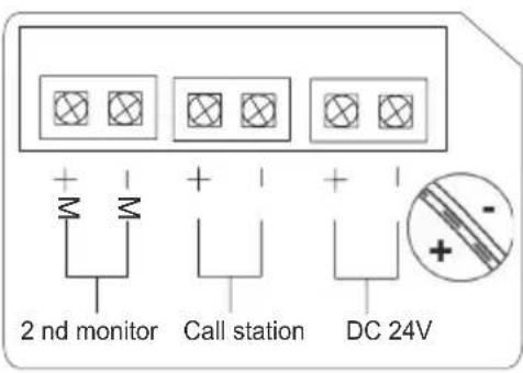

natural_image
Diagram of a device with an arrow pointing to a component, showing internal structure (no text or symbols)5 - INSTALLATIE VAN HET BUITENPANEEL
natural_image
Diagram showing two cable installation steps with exposed wires and connectors (no text or labels)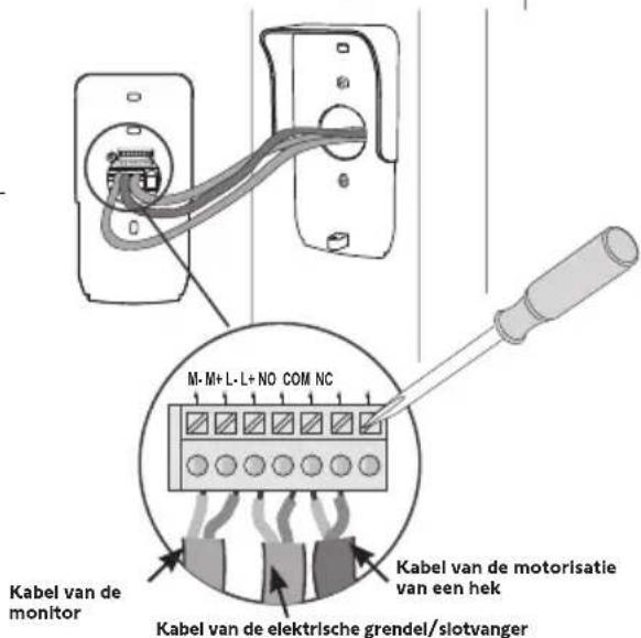
natural_image
Diagram of a door handle assembly showing two components with a cable or wire connection (no text or symbols)
natural_image
Diagram of a mechanical device with rotating components and directional arrows (no text or symbols)natural_image
Technical line drawing of a device with two views: one showing a circular dial and arrow, the other showing a multi-hole dial (no text or symbols)natural_image
Simple line drawing of a monitor connected to an electrical outlet (no text or symbols)6 - BEDIENINGSPANEEEL

Volgende
instelling


Omlaag


Bevestigen

Datuminstelling:
Dag / Maand / Jaar
Klokinstelling:

natural_image
Grid of nine simple icons including boxes, books, lightning, and power button (no text or symbols)

flowchart
graph TD
    A["Input"] --> B["Test"]
    B --> C["Output"]
natural_image
Black-and-white photo of a smiling man in a hoodie, displayed within a smartphone screen (no text or symbols visible)natural_image
Illustration of a mobile device with a blank screen and control buttons (no text or symbols)natural_image
Black-and-white portrait of a smiling man outdoors, wearing a hooded jacket (no visible text or symbols)natural_image
Black-and-white portrait of a smiling man outdoors, wearing a hooded jacket (no text or symbols visible)natural_image
Black-and-white photo of a smiling man in a hoodie, with blurred background and no visible text or symbols.natural_image
Black-and-white photo of a smiling man in a hooded jacket, with blurred background and no visible text or symbols.natural_image
Black-and-white photo of a smiling man in a hooded jacket, with blurred background and no visible text or symbols.natural_image
Black-and-white photo of a smiling man with a coffee cup icon, no visible text or symbols in the main image area.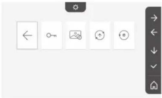
natural_image
User interface toolbar with navigation and rotation icons (no text or symbols)Tijdinstelling

Klokinstelling:
natural_image
Two small icons: a radio with signal waves and a musical note, displayed on a plain background (no text or symbols)
natural_image
Black-and-white photo of a sedan parked in front of a row of houses (no visible text or signage)Helderheidsinstelling

natural_image
Black and white photo of a sedan parked in front of residential houses with a solar panel icon on the right (no visible text or symbols)Kleurinstelling

natural_image
Black and white photo of a car parked in front of residential houses (no visible text or symbols)natural_image
Row of five icons: storage box, warehouse, lightbulb, and document icon (no text or symbols)natural_image
Line drawing of a rectangular electronic device with a labeled component and an arrow pointing to its side (no text or symbols on the device itself)flowchart
graph LR
    A["Image"] --> B["File Icon"]
Software bijwerken

natural_image
Pure electrical circuit lines without any symbols

natural_image
Diagram of a device with an arrow indicating direction, showing internal components and a small inset component (no text or symbols)natural_image
Diagram showing two cable installation steps with exposed wires and connectors (no text or labels)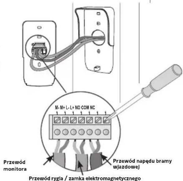
natural_image
Technical line drawing showing two mechanical components with internal connections and a directional arrow (no text or symbols)natural_image
Technical line drawing of a device with circular components and directional arrows, no text or symbols presentnatural_image
Simple line drawing of a monitor connected to an electrical outlet (no text or symbols)6 - INTERFEJS UŻYTKOWNIKA

Opuszczanie


Potwierdzenie
Ustawienie daty:
natural_image
Grid of nine simple icons including boxes, books, a lightbulb, and a battery, arranged in two rows (no text or symbols)
flowchart
graph TD
    A["Smoove"] --> B["Interaction"]
    C["Situo"] --> B
    B --> D["Return to UI"]
    style A fill:#f9f,stroke:#333
    style C fill:#f9f,stroke:#333
flowchart
graph TD
    A["Input"] --> B["Test"]
    B --> C["Output"]
PL Wideodomofon V®350
natural_image
Black-and-white photo of a smiling man in a hoodie, displayed within a smartphone screen (no text or symbols visible)natural_image
Illustration of a mobile device with control buttons and a blank screen (no text or symbols)natural_image
Front view of a mobile device with control buttons and a small icon (no readable text or symbols)natural_image
Black-and-white portrait of a smiling man outdoors, wearing a hooded jacket (no visible text or symbols)natural_image
Black-and-white portrait of a smiling man outdoors, wearing a hooded jacket (no text or symbols visible)natural_image
Black-and-white photo of a smiling man in a hoodie, with blurred background and no visible text or symbols.natural_image
Black-and-white photo of a smiling man in a hooded jacket, with blurred background and no visible text or symbols.natural_image
Black-and-white photo of a smiling man in a hooded jacket, outdoors with blurred background (no text or symbols visible)natural_image
Black-and-white photo of a smiling man in a jacket, with a coffee cup icon overlay (no readable text or symbols)Kolejne ustawienia to:

natural_image
User interface toolbar with navigation and refresh icons (no text or symbols)Ustawienie godziny

Ustawienie zegara:
natural_image
Two small icons: a radio with signal waves and a musical note, displayed on a plain background (no text or symbols)
Wybór melodii

natural_image
Black-and-white photo of a sedan parked in front of a row of houses (no visible text or signage)Ustawienie jasności

natural_image
Black and white photo of a sedan parked in front of a row of houses with a sun icon on the left (no visible text or symbols)Ustawienie koloru

natural_image
Black sedan parked in front of a residential house with smokestacks (no visible text or symbols)natural_image
Row of five icons: storage box, tablet, warehouse, lightbulb, and home (no text or symbols)PL Wideodomofon V®350
Przesyłanie zdjęć

natural_image
Line drawing of a rectangular electronic device with a label pointing to its side (no text or symbols on the device itself)Č. Název Popis
natural_image
Pure electrical circuit lines without any symbolsnatural_image
Technical line drawing of an electrical enclosure with wiring and socket (no text or symbols)
natural_image
Diagram of a device with an arrow pointing to a component, showing internal structure without any text or symbols.5 - MONTÁŽ VENKOVNÍHO OVLÁDACÍHO PANELU
natural_image
Diagram showing two cable installation steps with wires and connectors (no text or symbols)[3]. Připojte:
natural_image
Technical line drawing showing two mechanical components with internal connections and a directional arrow (no text or symbols)natural_image
Technical line drawing of a device with two views: one showing a circular dial and arrow, the other showing a multi-hole rotary knob (no text or symbols)natural_image
Simple line drawing of a monitor connected to an electrical outlet (no text or symbols)6 - UŽIVATELSKÉ ROZHRANÍ

natural_image
Grid of nine icons including boxes, books, lights, and a power button, displayed in a software interface (no text or symbols on icons)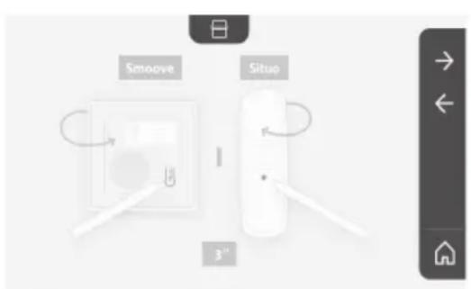
natural_image
Black-and-white photo of a smiling man in a hoodie, displayed within a tablet device interface (no readable text or symbols on the image itself)natural_image
Illustration of a mobile device interface with buttons and icons (no readable text or symbols)natural_image
Black-and-white portrait of a smiling man in a hoodie outdoors (no text or symbols visible)natural_image
Black-and-white portrait of a smiling man in a hooded jacket, with blurred background and no visible text or symbols.natural_image
Black-and-white photo of a smiling man in a hooded jacket, with blurred background and no visible text or symbols.natural_image
Black-and-white photo of a smiling man in a hooded jacket, with blurred background foliage and no visible text or symbols.natural_image
Black-and-white photo of a smiling man in a hooded jacket, with blurred background and no visible text or symbols.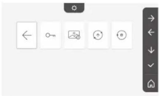
natural_image
User interface toolbar with five function icons (left, key, photo, refresh, download) arranged horizontally on a grid of squares, no text or symbols present.Nastavení času

Nastavení hodin:
natural_image
Two small icons: a radio with signal waves and a music note, displayed on a plain background (no text or symbols)- Hlasitost komunikace.


Výběr melodie

natural_image
Black-and-white photo of a sedan parked in front of a row of houses (no visible text or signage)Nastavení jasu

natural_image
Black and white photo of a sedan parked in front of residential houses with a solar panel icon on the right (no visible text or symbols)Nastavení barvy

natural_image
Black and white photo of a car parked in front of residential houses (no visible text or symbols)natural_image
Row of five icons: a box, a storage box, a house, and a lightbulb, displayed in a row with no text or symbols.Videotelefon V®350

Přenos fotografií

natural_image
Line drawing of a rectangular electronic device with a labeled component and an arrow pointing to it (no text or symbols beyond the label)flowchart
graph LR
    A["Image"] --> B["File Icon"]
natural_image
Line drawing of a smartphone rear panel with a small screen and label 'Lyase' (no text or symbols on the device itself)
natural_image
Black-and-white photo of a sedan parked in front of residential houses (no visible text or signage)
natural_image
Black sedan parked in a residential area with houses and a street view (no visible text or symbols)
natural_image
Black sedan parked in front of residential houses (no visible text or symbols)
natural_image
Row of five icons: a box, a document, a garage, and a lightbulb, displayed on a white background with a right-side navigation bar (no text or symbols on icons)
natural_image
Two small icons: a radio button and a musical note, displayed on a plain background with no text or symbols.

◦ نصال.


◦ نغمة.

natural_image
Simple line icon of a person crossing a diagonal line, no text or symbols presentnatural_image
Grid of icons including clock, calendar, speaker, music note, sun, trash bin, and directional arrow (no text or labels)natural_image
Black-and-white portrait of a smiling man with a mustache wearing a hooded jacket, outdoors with blurred background (no text or symbols visible)
natural_image
Black-and-white photo of a smiling man in a hooded jacket, with blurred background and no visible text or symbols.natural_image
Black-and-white photo of a smiling man in a hooded jacket, outdoors with blurred background (no text or symbols visible)natural_image
Illustration of a mobile device with a blank screen and control buttons (no text or symbols)natural_image
Black-and-white portrait of a smiling man outdoors, wearing a hooded jacket (no visible text or symbols)natural_image
Black-and-white portrait of a smiling man in a hooded jacket, with blurred background foliage (no text or symbols visible)natural_image
Black-and-white photo of a smiling man in a hoodie, displayed within a tablet device (no text or symbols visible)natural_image
Grid of nine icon buttons including boxes, books, a lightbulb, and a battery, displayed in a software interface (no text or symbols on icons)natural_image
Simple line drawing of a monitor connected to an electrical outlet (no text or symbols)١٠-٦ Shanghai Executive Department 1-1
natural_image
Diagram of a device's internal rotation mechanism with arrows indicating direction (no text or symbols)
natural_image
Line drawing of a portable electronic device with two circular buttons and a speaker grille (no text or symbols)natural_image
Pure electrical circuit lines without any symbols
natural_image
Technical diagram of a mechanical assembly with labeled parts (no text or symbols present)natural_image
Diagram of a device with two components, one showing internal wiring and the other showing a curved cable or connector (no text or symbols present)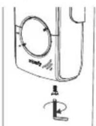
natural_image
Simple line drawing of a washing machine with a handle and valve (no text or symbols)natural_image
Pure electrical circuit lines without any symbols

natural_image
Diagram of a device with an open panel and internal cable, showing no text or symbolsالوصف(shرحExplanation)


- - BIENVENUE 2
- - INFORMATIONS IMPORTANTES - SÉCURITÉ ---- 2
- - INSTALLATION DE LA PLATINE DE RUE
- - INTERFACE UTILISATEUR
- FR Visiophone V®350
- Réglage de l'heure
- Choix de la mélodie
- Transfert des photos
- - INSTALLATION DER AUSSENSTATION
- - INSTALLAZIONE DELLA PULSANTIERA ESTERNA
- - INTERFACCIA UTENTE
- Ρύθμιση της ώρας
- - INTERFAZ DE USUARIO
- Ajuste de la fecha:
- Ajuste del reloj:
- Ajuste de la hora
- Ajuste del color
- Traspaso de fotos
- - INTERFACE UTILIZADOR
- Acerto da data:
- Acerto do relógio:
- Acerto da hora
- Seleção da melodia
- Regulação da cor
- - IMPORTANT SAFETY INFORMATION 2
- - PRODUCT PRESENTATION 3
- - INSTALLING THE MONITOR----7
- - INSTALLING THE DOOR STATION 8
- - USER INTERFACE 10
- - MAINTENANCE 22
- - TECHNICAL DATA 23
- About Somfy
- Assistance
- Warranty
- - IMPORTANT INFORMATION - SAFETY
- General information
- General safety instructions
- Conditions for use
- Recycling and disposal
- Meaning of logos on the mains adapter
- Composition of the kit
- Product description
- Monitor
- No. Designation Description
- Door station
- Standard installation
- - INSTALLING THE MONITOR
- NB
- - INSTALLING THE DOOR STATION
- Fastening and wiring the door station
- Connecting the door station
- Connecting to a Somfy gate motorisation
- Connecting to an electric latch/lock
- Fitting the name tag
- Powering on the installation
- - USER INTERFACE
- The video entry phone
- Start screen and basic settings
- Setting the date:
- Setting the clock:
- Choice of ring tone melody:
- Setting the ring tone volume:
- Controlling Somfy RTS wireless equipment
- Adding Somfy RTS equipment
- EN V®350 video entry phone
- Responding to a visitor
- Stored photos of visitors
- Subsequent settings
- Setting the time
- Setting the date
- Adjusting the volume
- Choice of ring tone
- Setting the contrast
- Setting the brightness
- Setting the colour
- Memorising a group of RTS products
- Deleting an RTS product
- Setting the electric latch activation time
- Transferring photos
- Software update
- Resetting the parameters
- Door station settings
- Setting the speaker volume
- Activating or deactivating the audible beep of the call button:
- - MAINTENANCE
- Cleaning
- - WELKOM 2
- - BELANGRIJKE INFORMATIE - VEILIGHEID 2
- - PRODUCTBESCHRIJVING 3
- - PRODUCTBESCHRIJVING
- - INSTALLATIE VAN HET BUITENPANEEL
- - BEDIENINGSPANEEEL
- Datuminstelling:
- Klokinstelling:
- Tijdinstelling
- Helderheidsinstelling
- Kleurinstelling
- Software bijwerken
- - INTERFEJS UŻYTKOWNIKA
- Ustawienie daty:
- PL Wideodomofon V®350
- Ustawienie godziny
- Wybór melodii
- Ustawienie jasności
- Ustawienie koloru
- Przesyłanie zdjęć
- - MONTÁŽ VENKOVNÍHO OVLÁDACÍHO PANELU
- - UŽIVATELSKÉ ROZHRANÍ
- Nastavení času
- Výběr melodie
- Nastavení jasu
- Nastavení barvy
- Videotelefon V®350
- Přenos fotografií
- ١٠-٦ Shanghai Executive Department 1-1
Brand : SOMFY
Model : V350
Category : Video Intercom