Respiro 100 RD - Fan Thermex - Free user manual and instructions
Find the device manual for free Respiro 100 RD Thermex in PDF.

| Product type | Single-flow heat recovery ventilator (HRV) |
| Brand | Thermex |
| Model | Respiro 100 RD |
| Use | Indoor air renewal, wall-mounted installation |
| Power supply | 220-240 V ~ 50 Hz, single-phase |
| Power consumption | 3.9 W (speed 1), 5.9 W (speed 2), 7.9 W (speed 3) |
| Airflow | 15 m³/h (speed 1), 22.5 m³/h (speed 2), 30 m³/h (speed 3) |
| Noise level at 3 m | 19 dB(A) (speed 1), 24 dB(A) (speed 2), 29 dB(A) (speed 3) |
| Maximum heat recovery | 93 % |
| Average heat recovery | 70 % (speed 1), 74 % (speed 2), 78 % (speed 3) |
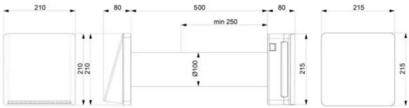
| Duct diameter | 100 mm |
| Maximum wall thickness | 400 mm (integrated duct) |
| Minimum wall thickness | 250 mm |
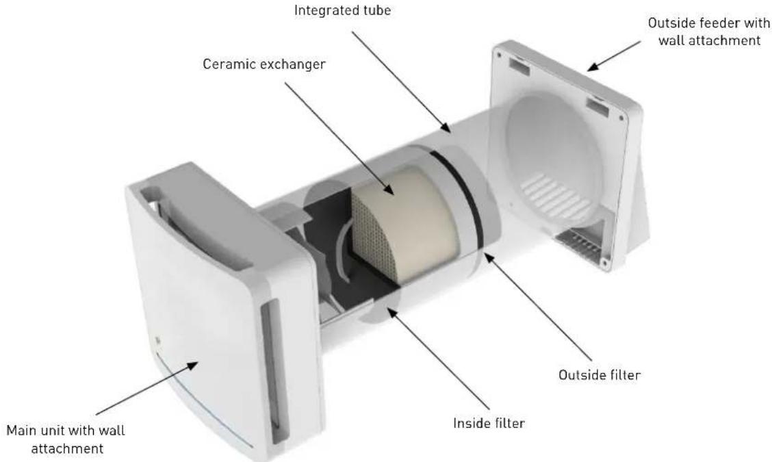
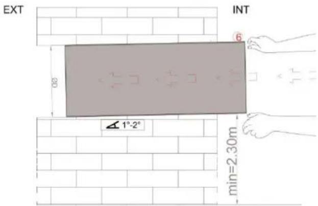
| Minimum distance from floor | 2.30 m |
| Protection rating | IPX4 |
| Electrical class | Class II |
| Operating temperature | -20 °C to +50 °C |
| Integrated sensors | Relative humidity and brightness |
| Controls | Wireless remote control (CR2025 battery) and switches on unit |
| Operating modes | Automatic, Monitoring, Manual (3 speeds), Intake/Extraction, Flow direction |
| Master-slave function | Yes, up to 4 units (1 master + 3 slaves) |
| Maintenance and cleaning | Clean filters and ceramic heat exchanger every 3 months. Replace filters every 2 years. Filter alarm after 2000 hours |
| Available spare parts | Replacement filters, remote control battery CR2025 |
| Warranty | Manufacturer warranty (excluding assembly/disassembly costs, installation defects) |
Frequently Asked Questions - Respiro 100 RD Thermex
User questions about Respiro 100 RD Thermex
0 question about this device. Answer the ones you know or ask your own.
Ask a new question about this device
Download the instructions for your Fan in PDF format for free! Find your manual Respiro 100 RD - Thermex and take your electronic device back in hand. On this page are published all the documents necessary for the use of your device. Respiro 100 RD by Thermex.
USER MANUAL Respiro 100 RD Thermex
natural_image
Technical line drawing of a mechanical component with flanged ends and a cylindrical body (no text or symbols)ES
ESPAÑOL
natural_image
Top-down schematic of a washing machine with a circular chamber and mounting brackets, set against a brick wall background (no text or symbols)natural_image
Top-down schematic of a device casing with a circular center and red indicator lights, set against a brick wall background (no text or symbols)natural_image
Technical line drawing of a mechanical housing component, showing front and side views (no text or symbols)natural_image
Line drawing of a hand holding a remote control device (no text or symbols)LISTA DE COMANDOS
HI - HI - H2 - H2 - H3 - H3
RESETEO DEL PRODUCTO
natural_image
Line drawings of a vacuum cleaner and a showerhead device (no text or symbols)natural_image
Line drawing of a handheld device with a coiled cable and connector (no text or symbols)ES
natural_image
Line drawing of a hand cleaning a circular fan inside a rectangular device (no text or symbols)4) PUESTA EN SERVICIO DEL PRODUCTO DESPUÉS DE LA LIMPIEZA
natural_image
Line drawing of a device with two electrical outlets connected to a rectangular box (no text or symbols)1. Encendido
natural_image
Line drawing of a rectangular electronic device with a handle and base (no text or symbols)- We recommend you check the state of the device and that it works as soon as you take it out of the packaging. Check that the product is the one you ordered and that the data on the data sheet are in line with your requirements.
- It must be installed in accordance with the regulations in force in each country.
- If the product works as an extractor in a room in which a boiler or other type of system needing air for its combustion system is installed, check that the room's air intake is of the correct size.
- The extractor's exhaust cannot be connected to a pipe used to discharge fumes from devices powered by gas or other fuels.
- Do not put any objects through the protective grille.
- Do not remove the front mesh when the extractor is working. The extractor must always work with the front mesh correctly mounted.
GENERAL
WARNINGS
The objective of this manual is to detail all the information useful for the installation, start-up and safe use of the device.
Given that our product is in continual development, Soler & Palau reserves the right to make changes to this manual without notice.
The machine must be installed by an authorised person.
GENERAL SAFETY RULES
After installation, no risks to health and safety and the environment should be entailed, in accordance with EC directives. This goes for all our products used in the installation.
The following general warnings are important:
- Follow the safety instructions to avoid any type of damage to the fans or to persons.
- The technical characteristics of this manual may be changed.
- The fan motors cannot be modified.
- The fan motors must be powered with single phase 230V/50Hz alternating current.
- For installation according to EC guidelines, the device must be connected to the mains in accordance with applicable regulations.
- The machine must be mounted so that, in normal conditions, there is no risk of coming into contact with moving parts and/or low voltage. This in accordance with the regulations applicable to electrical devices.
- Before doing any work on it, always disconnect it from the mains.
- Use the appropriate tools. Use the device only for the use it has been designed for.
- This product can be used by children over 8 years of age and by persons with reduced physical, sensory or mental capabilities or lacking experience and knowledge only if supervised and duly informed about how to use the device safely. Children must not play with the machine. Cleaning and maintenance by the user must not be done by unsupervised children. (7.12, EN 60335-1).
GUARANTEE AND LIABILITY
Guarantee
The guarantee does not cover:
- The mounting and dismounting costs.
- Faults that, according to Soler & Palau, are attributable to wrong installation, tampering, negligence or accident.
- Faults deriving from tampering or a repair done by persons without Soler & Palau's authorisation.
- To return a defective part, contact the installer/dealer.
Liability
The machine is designed for a ventilation system enabling air renewal for extractions from homes. Soler & Palau is not liable for damage caused by:
- Improper use;
• Normal wear of the components; - Failure to observe the instructions in this manual regarding safety, use and start-up;
- The use of parts not supplied by Soler & Palau.
INTENDED USE
The product is built according to industry standards and is installed to provide constant air replacement inside the room. The recovery unit can be installed in both homes and public premises.
The product has a ceramic heat exchanger that accumulates heat during the extraction of air from the room, while during the air intake from the outside the device transfers the heat stored in the exchanger to the cold air coming in.
The product must be installed on a wall. The tube the ceramic exchanger is placed inside is provided for a wall of a maximum thickness of 500mm; the tube can be shortened to a minimum of 250mm.
The air extracted or taken in by the product must not contain flammable or explosive mixtures, chemical vapours, dusts, oils and other pathogenic substances.
To enhance the RESPIRO 150 and RESPIRO 150 RD systems' performances, we recommend installing the recovery units in pairs so that when one is in extraction the other is in intake.
EN
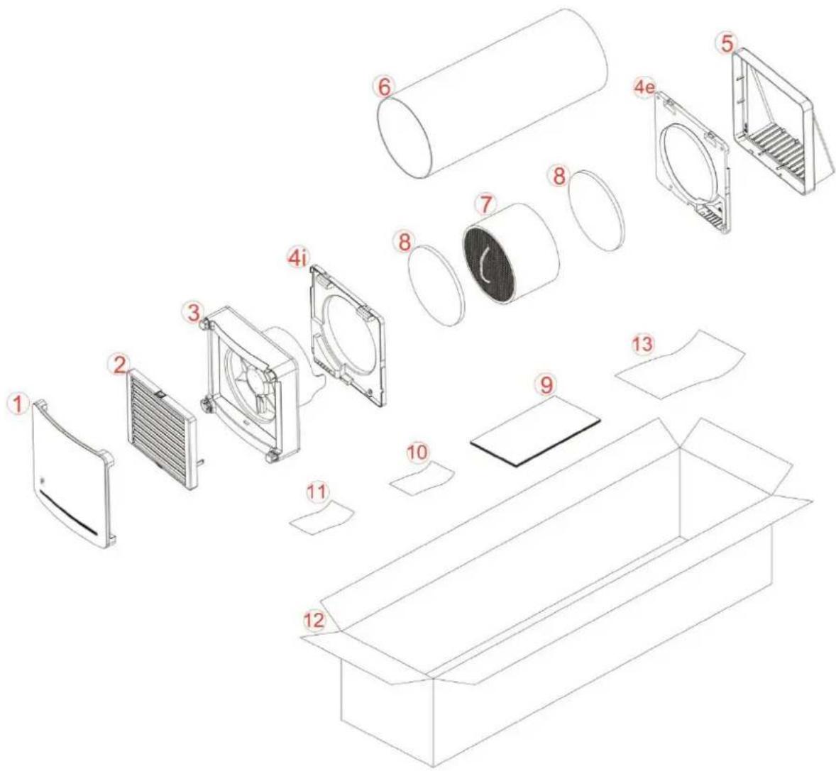
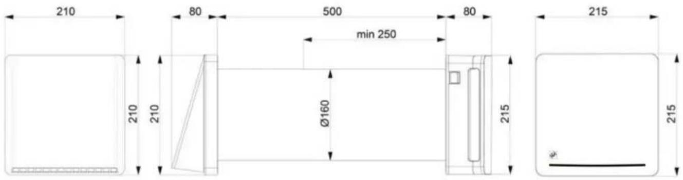
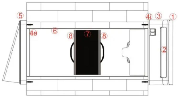
Description of the product
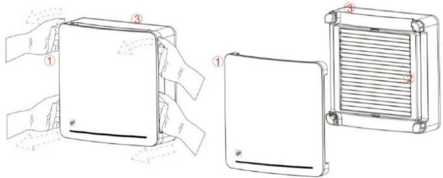
- Front embellisher and damper cover
- Damper
- Main unit
4i. Inside wall fixture with electrical connections
4e. Outside wall fixture - Outside feeder
- Integrated tube 500mm
- Ceramic exchanger
- Filters
- Installation and maintenance manual
- General warnings
- RAEE guarantee card
- Product packaging
- Product extraction warning
TECHNICAL PARAMETERS
The recovery unit is classified as a Class II product.
The degree of protection is IPX4.
The recovery unit has been designed to be installed in closed places. The operating temperatures are between -20°C and 50°C with maximum relative humidity 80%.
The design of the recovery unit is constantly evolving, therefore, certain models could differ from that detailed in this manual.
RESPIRO 100 / RESPIRO 100 RD
RESPIRO 100
| Speed 123 | |||
| Voltage at 50Hz 220-240 Vac 220-240 Vac x | |||
| Power [W] 3,97,9 x | |||
| Capacity [m3/h] 1530 x | |||
| Noise at 3 m [dB] 1929 x | |||
| Max heat recovery 93% 93% | x | ||
| Average heat recovery | 70% 78% | x |
RESPIRO 100 RD
| Speed 123 | |||
| Voltage at 50Hz 220-240 Vac 220-240 Vac 220-240 Vac | |||
| Power [W] 3,9 5,9 7,9 | |||
| Capacity [m3/h] 15 | 22,5 | 30 | |
| Noise at 3 m [dB] | 19 24 29 | ||
| Max heat recovery 93% 93% 93% | |||
| Average heat recovery | 70% 74% 78% | ||
RESPIRO 150 / RESPIRO 150 RD
EN
| RESPIRO 150 | |||
| Speed 1 2 3 | |||
| Voltage at 50Hz 220-240 Vac 220-240 Vac x | |||
| Power [W] 4,9 8,9 x | |||
| Capacity [ m^3 /h] 30 60 x | |||
| Noise at 3m [dB] 13 23 x | |||
| Max heat recovery 93% 93% x | |||
| Average heat recovery | 70% 78% x | ||
| RESPIRO 150 RD | |||
| Speed 1 2 3 | |||
| Voltage at 50Hz 220-240 Vac 220-240 Vac 220-240 Vac | |||
| Power [W] 4,9 6,9 8,9 | |||
| Capacity [m3/h] 30 45 60 | |||
| Noise at 3m [dB] 13 20 23 | |||
| Max heat recovery 93% 93% 93% | |||
| Average heat recovery | 70% 74% 78% | ||
CONSTRUCTION
The product is formed by a main operating unit with wall attachment which will be placed inside the room, an integrated tube containing the ceramic exchanger and filters, an outside feeder with wall attachment.
INSTALLATION
The product must only be installed by qualified staff. Make sure that the room's mains network is disconnected before carrying out the electrical assembly operations.
The device must not be installed near to curtains, blinds, etc. as these could jeopardise its correct operation.
Make sure that, once installed, the blades of the impeller are placed at least 2.30m away from the floor. If installing several devices, the distance between each product must be at least 3 metres.
Before mounting the product read the instruction manual carefully and make sure you have all the equipment you need for the installation.
Follow the instructions of this manual carefully.
1) ASSEMBLY
After identifying the area in which you intend to install the product, mark the centre of the through-hole to be made in the wall.
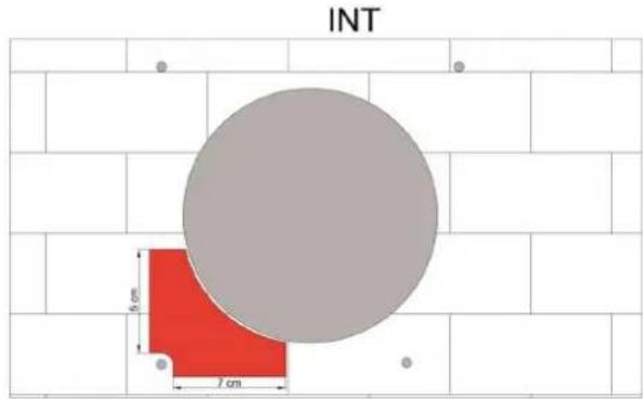
Make sure that, with respect to the centre of the hole for the integrated tube, there is a free space on the inside and outside wall for a radius of 15cm, which corresponds to the product's dimensions. Make sure that inside this area there is no interference with walls and non-removable objects.
Hole diameter for installation is:
• RESPIRO 100 ∅ 100 mm
• RESPIRO 150 ∅ 160 mm
The hole made in the wall must be a through hole with a slope of 1^-2^ towards the outside. To use the integrated tube provided, the wall must not be more than 500mm thick. To install the product, the receiving wall cannot be less than 250mm thick. Once you have made the though hole in the wall, position the integrated tube [6] inside it.

Make sure the length of the integrated tube (6) is the same as the wall thickness. The tube must end up flush with the inside and outside walls.
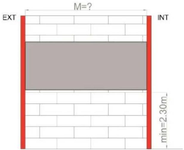
The "M" dimension cannot be less than 250mm, if it is the wall is not suitable for the product. Adapt the tube, if necessary, to the wall's thickness with the appropriate tools, in the appropriate manner, as shown below:
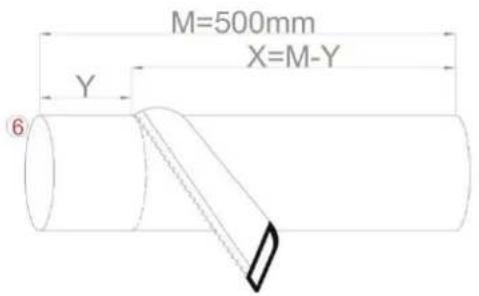
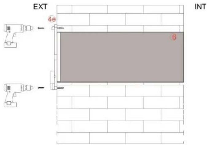
Once you have adapted the length of the integrated tube (6) to the exact thickness of the wall, position the outside wall attachment (4e) on the outside wall as shown in the image below:
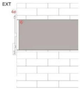
Insert the centring diameter of the wall attachment (4e) into the integrated tube (6).
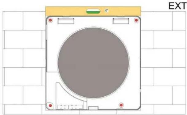
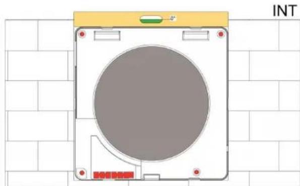
Once the tube has been centred, trace the fixture holes on the outside wall using the external wall attachment (4e) and a spirit level to guarantee the precision as shown in the image below:

natural_image
Diagram of a device casing with a circular center and mounting brackets, set against a tiled wall (no text or symbols)Make the holes and insert the plugs for the wall fixture. Screw the outside wall attachment (4e) into the outside wall.
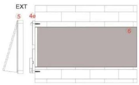
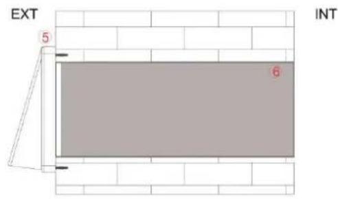
Snap the outside feeder (5) onto the outside wall attachment (4e) as shown in the images.
IN
2) ELECTRICAL CONNECTIONS
The product must only be installed by qualified staff. Make sure that the room's supply voltage complies with the power declared on the product's data sheet.
Make sure that the room's mains network is disconnected before carrying out the electrical assembly operations.
Identify the product version you have and read all the instructions concerning your version's electrical connections carefully.
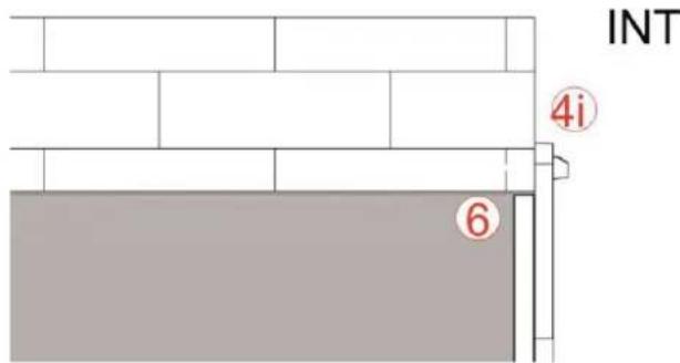

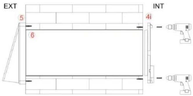
As for the tracing of the outside holes, first insert the centring diameter of the inside wall attachment (4i) into the integrated tube (6) as in the image above. Using a spirit level trace and make the 4 holes for the wall fixture of the inside wall attachment (4i).
natural_image
Top-down schematic of a device casing with a circular chamber, mounted on a grid background (no text or symbols)Unlike the outside wall fixture, on the inside wall you must bring up the supply leads to be connected to the stripped wires supplied with the product.
Bring the cables out of the wall in the area shown.
Connection of a supply cable from the wall
Once you have inserted the plugs, before screwing in, extract the terminal block from the inside wall fixture (4i) and pass the cables through the base.
Connection of an outside power cable
Break the plastic tabs indicated in the below images.

natural_image
Technical line drawing of a mechanical housing component, showing front and side views with no text or symbolsExtract the terminal block from the inside wall fixture and pass the cables through the base, fixing the cable tie with the screws provided.
Fix the inside wall fixture (4i) to the wall and execute the electrical connections as described in the following paragraphs.
Before making the connection, the power cables (live and neutral) must be situated in the area of the outlet from the wall.
Take the inside wall fixture (4i) and the tools needed to connect the mains network to the terminal block.
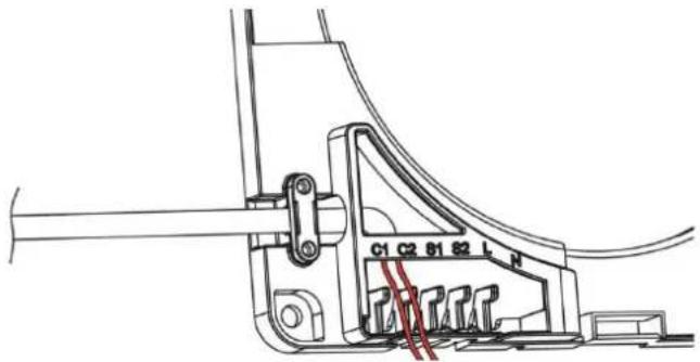
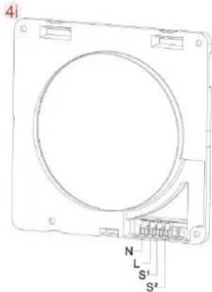
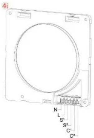
Properly connect and secure the mains power cables to the terminal block. "N" and "L" indication.
Connection with remoting of wall commands
It is also possible to remote the wall on-off and speed selection controls. Follow the instructions in the "DIRECT CONNECTION" paragraph concerning the modes of connection to the electricity network.
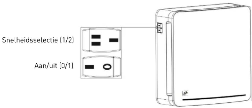
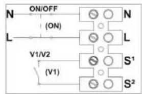
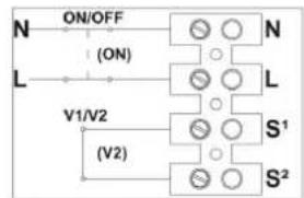
To control the product with wall-mounted switches, during operation the switches on the product must always be positioned on 1 as detailed in the image (Y).
To turn the product on with wall switches, connect a bipolar switch in series to the "L" and "N" supply as detailed in the picture (a).
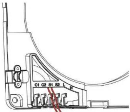
Connections are executed as detailed below:
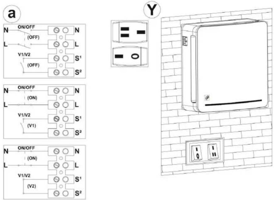
To control the speeds by wall-mounted switch connect the switch's two terminals to the heads "S1" and "S2" as shown.
2b) RESPIRO 100RD / RESPIRO 150 RD
Power supply connection
Before making the connection, the power cables (live and neutral) must be situated in the area of the outlet from the wall.
Take the inside wall fixture (4i) and the tools needed to connect the mains network to the terminal block.
Properly connect and secure the power cables to the terminal block. "N" and "L" indication.
It is possible to remote the wall on-off controls. To control the product with integrated switches, during operation the switches on the product must always be positioned on 1 as detailed in the image (Y).
To turn the product on with wall switches, connect a bipolar switch in series to the "L" and "N" supply as detailed in the picture (a).
It is also possible to connect the product to the intelligent home network by serialising the power to enable programming of the on and off.
Execute the connections as in the below images:

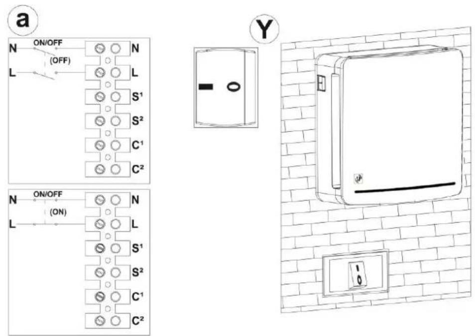
Communication with slave products
If it has been planned to install one or more products cascaded from the main unit or to set this up for a future connection, refer to the below images to enable communication between the main unit and the cascaded units.
flowchart
graph TD
    subgraph MASTER
        N --> S1
        L --> S1
        S1 --> C1
        S2 --> C1
        C2 --> C2
    end
    subgraph SLAVE1
        N --> S1
        L --> S1
        S2 --> C1
        C2 --> C2
    end
    subgraph SLAVE2
        N --> S1
        L --> S1
        S2 --> C1
        C2 --> C2
    end
    subgraph SLAVE3
        N --> S1
        L --> S1
        S2 --> C1
        C2 --> C2
    end
    N --> L
    L --> N
    style MASTER fill:#f9f,stroke:#333
    style SLAVE1 fill:#ccf,stroke:#333
    style SLAVE2 fill:#ccf,stroke:#333
    style SLAVE3 fill:#ccf,stroke:#333
We advise you to use different coloured cables to avoid inverting the connections.
Attention: As indicated in the connection diagram, the master unit, to be configured as such, must not have other devices connected in the C1 and C2 terminal blocks.
Attention: It is necessary to adhere to the connection between the S1-C1 and S2-C2 signals to avoid causing damage to the electronic device.
Configuration of master product: slave
Check that the master unit doesn't have other devices connected in the terminal blocks (C1 and C2), then turn it on. After the first 10 seconds during which the red LED will remain steady, the product will emit two alternating white and red light pulses and will be configured automatically as MASTER. Only once the product has been identified as main MASTER unit it is possible to start configuring the SLAVE1.
Do not send any command from remote to the slave units.
Make sure the MASTER unit starts working before turning on the next (SLAVE) unit by means of switch "0/1" in order to give the MASTER unit time to configure the SLAVE units in the desired sequence.
Turn on the SLAVE unit in sequence with switch 0/1, as explained below.
Each unit must only be turned on after the previous unit has effectively started working:
- Master Unit
- Slave 1 with operation opposite to Master
- Slave 2 with operation same as Master
- Slave 3 with operation opposite to Master
Attention: If the product is not configured correctly (MASTER or SLAVE) the RESET function can be used, which resets the product to factory conditions. This procedure is explained in the remote control PRODUCT RESET paragraph (page 22).
3) CONCLUSION OF THE ASSEMBLY
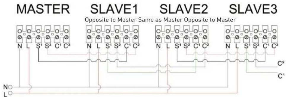
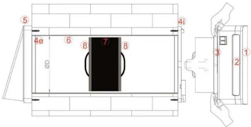
Having done the connection, put the terminal block and the cables back in their housing. Insert the ceramic exchanger (7) with the relative filters (8), positioning it half way along the integrated tube (6) as shown in the below image:
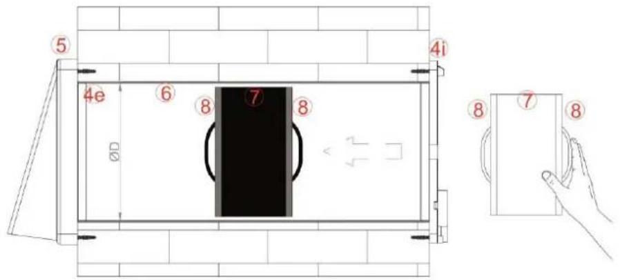
Snap the main unit (3), together with the damper components (2) and front embellisher (1) already mounted on it, into the wall attachment (4i) until all the teeth are fastened.
Make sure you install the main unit on the wall with the switches at the top left.
REMOTE CONTROL (RD VERSION)
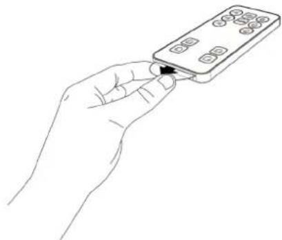
REMOVAL OF PROTECTIVE LABEL
To be able to use the remote control, remove the protective label, as shown below.
natural_image
Line drawing of a hand holding a remote control device (no text or symbols)LIST COMMANDS
| S Surveillance function | 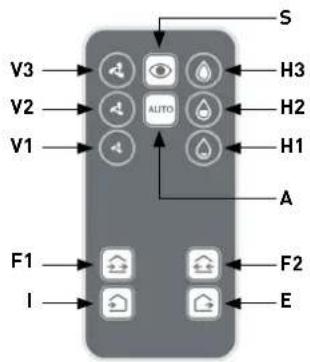 |
| A Automatic mode | |
| V Speed selection | |
| H Selection of relative humidity threshold | |
| F Direction of airflow | |
| I Air intake function | |
| E Air extraction function |
COMMANDS INSTRUCTIONS
S: Surveillance function (standby mode)
By pressing the "SURVEILLANCE" button, the product stays in standby mode with the damper closed but with the sensors active. If the remove humidity parameters should exceed those set, the product automatically starts extracting the air at the maximum speed until the values are restored and then returns to standby mode. In the case of several units, all the units go into SURVEILLANCE mode. This function is very useful if the user is absent for long periods.
Response:
| Light pulse on activating the mode | Red ● |
| Periodic light pulse (every 1 min.) active mode | White/Red ○ ● |
| Constant light pulse Beyond Threshold value | Red ● |
A: Automatic mode
Automatic mode provides operation at 70 seconds in air extraction and 70 seconds in air intake at average speed.
By pressing the "AUTO" button, the product executes the automatic control of the active sensors (twilight, hygrostat); in the case of values beyond the set threshold, the product will extract the air from the room at maximum speed until the threshold value is restored. In the case of several units, all the units go into AUTOMATIC mode.
The product is fitted with a twilight sensor that when the light intensity falls reduces the operating speed to the minimum to reduce the noise generated by the air.
Response:
| Light pulse on activating the mode | White/Red ○ ● |
| Periodic light pulse (every 1 min.) active mode Neutral | |
| Constant light pulse Beyond Threshold value | Red ● |
V: Speed selection
By pressing the "SPEED SELECTION" commands, the unit goes into manual mode enabling the desired speed to be defined, keeping it working at 70 seconds in air extraction and 70 seconds in air intake. In the case of several units, all the units work at the selected speed.
Attention: the sensors are not active in manual mode.
Response:
| Light pulse on activation of speed 1 | 1 White ○ |
| Light pulse on activation of speed 2 | 2 White ○○ |
| Light pulse on activation of speed 3 | 3 White ○○○ |
H: Selection of relative humidity threshold
It is possible to change the hygrostat trigger point threshold to adapt the value to the type of environment where it is installed. Once the relative humidity value set has been exceeded, the unit continuously extracts air at the maximum speed until the relative humidity read returns to below the set value. In the case of several units, all the products extract air until the set threshold is reached. The default set value is "Level H2", which corresponds to RH=55%.
Attention: when first turned on the product executes the auto-calibration of the hygrostat. It is possible that during this phase the "EXTRACTION" function will be activated to bring the room's humidity below the level required for this auto-calibration.
Response:
| Light impulse on activation of the H1 value (RH: 40%) | 1 Red ● |
| Light impulse on activation of the H2 value (RH: 55%) | 2 Red ●● |
| Light impulse on activation of the H3 value (RH: 70%) | 3 Red ●●● |
F: Direction of airflow (function can be activated if there are at least 2 units or multiple coupled units)
By pressing the "DIRECTION OF AIRFLOW" button the units generate an airflow that provides intake only and extraction only simultaneously for the desired time, always keeping the atmosphere balanced. According to the button pressed, the air intake and extraction direction can be reversed.
Attention: the sensors are not active in this function.
Attention: the speed can be modified through the V commands pressed previously to those F.
Response:
| Light pulse on activating the mode | 2 Red / 3 seg. / 2 Red ●● III ●● |
| Periodic light pulse (every 1 min.) active mode | Red ● |
I: Air intake function
By pressing the "AIR INTAKE FUNCTION" the product intakes air. In the case of several units, all of them intake air simultaneously until another command is given by the user.
Attention: the sensors are not active in this function.
Response:
| Light pulse on activating the mode | 1 Red / 3 seg. / 1 Red ● III ● |
| Periodic light pulse (every 1 min.) active mode | Red ● |
E: Air extraction function
By pressing the "AIR EXTRACTION FUNCTION" the product extracts air. In the case of several units, all of them extract air simultaneously until another command is given by the user.
Attention: the sensors are not active in this function.
Respuesta:
| Light pulse on activating the mode | 1 Rojo / 3 seg. / 1 Rojo ● III ● |
| Periodic light pulse (every 1 min.) active mode | Rojo ● |
COMMISSIONING
- Every time you turn on the RESPIRO RD (using the "0/1" switch) you have to wait 20 seconds before the unit will respond to remote control orders.
During the first 15s, the unit is powering up. In this state the red LED is on.
Once the red LED has turned off, another 5 seconds pass until we see a white blink.
Only after flashing white will the unit respond to remote control orders.
- It is important not to press any button until we have seen the white blink, otherwise the unit could be blocked.
- The fan may take up to a minute to start as it will not start rotating until the damper is fully open.
- Every time you send an order to the RESPIRO RD, you are sure that the unit has received the order by checking that the white LED blinks.
- Every time you unplug the unit, it returns to AUTOMATIC MODE at the next start-up.
FILTER ALARM RESET
Every 2000 hours of operation the indicator light at the bottom right will emit a continuous red light signal. The product will continue to operate by keeping the last command received.
To reset the hour counter inside the unit, press the key sequence detailed below (refer to the image of the remote control on page 1):
HI - HI - H2- H2- H3- H3
PRODUCT RESET
- Turn on the unit using the "0/1" switch. The red LED lights up.
- Press the "SUPERVISION MODE" button 5 times. It is important that no time elapses between step 1 and 2, otherwise you will have to start over.
- Wait 30 seconds. Verify that the red LED stays on permanently.
- Turn off the unit with the "0/1" switch and leave it off for about 15 seconds.
- Turn on the unit with the "0/1" button and do not press any button on the remote control.
- Wait for the red LED to turn off, then wait for the LED to blink white after a few seconds.
- Once the white flash is displayed, the unit will restart. Pay attention to the "START UP" paragraph before proceeding.
REPLACEMENT OF REMOTE CONTROL BATTERY
| After a long period of use, the remote control's battery may need replacement. The battery should be replaced when the product no longer responds to the commands sent by the remote control.The battery model to purchase is CR2025 3V.As in the image on the right press the lever inwards on the remote control (1), and extract the battery support by pulling it towards you (2). | 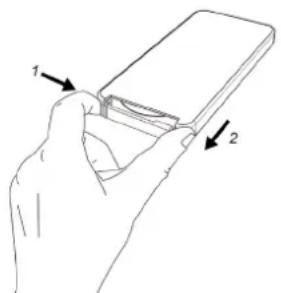 |
| After taking out the run-down battery, dispose of it in the appropriate containers as defined by the regulations in your country. Replace it with a new battery of the same model, positioning it as in the image on the right.Re-insert the battery support with the new battery. | 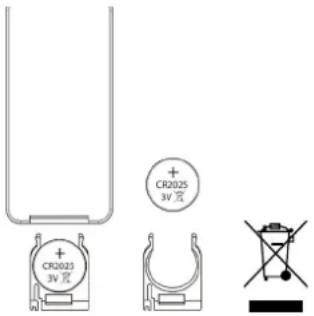 |
MAINTENANCE
All the device's maintenance operations are exclusively aimed at qualified staff.
Make sure that the room's mains network is disconnected before carrying out maintenance operations.
Once installed, the product's components should be arranged as shown in the above image.
1) INDICATION OF MAINTENANCE PERIOD
We advise cleaning the filters (8) and the ceramic exchanger (7) every 3 months.
We advise changing the filters every 2 years. Contact your dealer for delivery of replacement filters.
This version does not have an alarm for cleaning/replacement of filters.
Every 2000 hours of operation the indicator light at the bottom right will emit a continuous red light signal. During the alarm, each remote control, except for the filter reset combination, will be disabled. The product will continue to operate with the last command received.
Clean the exchanger and the filters as specified in the paragraph. Replace the filters when necessary.
2) CLEANING OF FILTERS AND EXCHANGER
Remove the main unit (1+2+3) from the wall using a flat-head screwdriver to actuate the hook placed bottom centre of the unit as shown below.
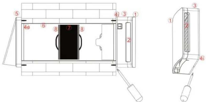
Once the functioning unit has been unfastened from the wall (4i) extract it with your hands, pulling hard as in the image below:
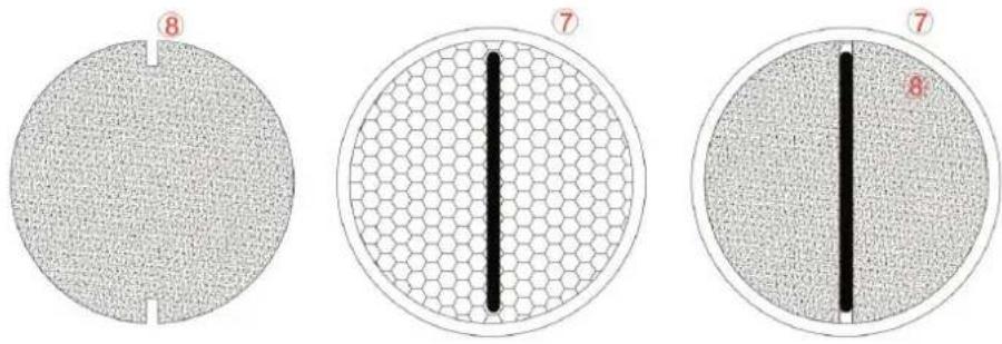
Extract the ceramic exchanger along with the filters (8+7+8) , pulling the cord towards you as shown in the below image.
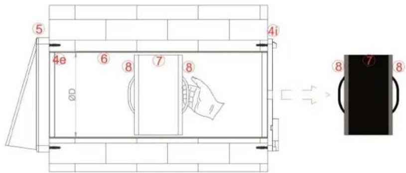
Remove the filters (8) from their housing and clean them, aspirating the residual dirt with a vacuum cleaner or washing them under running water, drying them carefully before putting them back.
EN
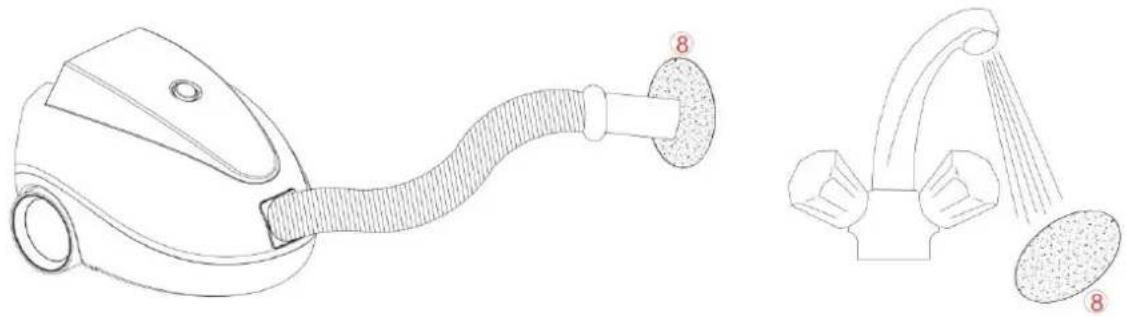
natural_image
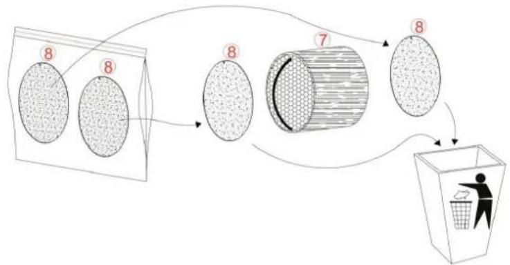
Line drawings of a vacuum cleaner and a showerhead device (no text or symbols)If the filters (8) are worn (indicative time 2 years) change them, ordering replacements from your dealer.
flowchart
graph TD
    A["8"] --> B["8"]
    B --> C["7"]
    C --> D["8"]
    D --> E["60% Recycling Box"]
    style A fill:#f9f,stroke:#333
    style B fill:#f9f,stroke:#333
    style C fill:#f9f,stroke:#333
    style D fill:#f9f,stroke:#333
    style E fill:#ccf,stroke:#333
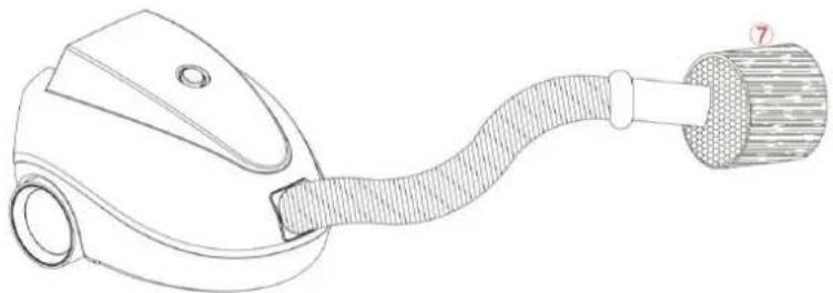
During the filter (8) cleaning/replacement operations also aspirate any residual dirt in the ceramic exchanger. DO NOT WASH THE CERAMIC EXCHANGER WITH WATER.
natural_image
Line drawing of a handheld device with a coiled cable and handle (no text or symbols)Once you have done the cleaning operations, position the filters (8) in their housing on the exchanger (7), inserting the filter slits under the cord as shown in the below image:
3) CLEANING OF DAMPER AND IMPELLER
After cleaning the filters and the exchanger put them back in their housings.
Take the main unit group (1+2+3) and remove the embellisher cover (1) removing the top hooks first and then the bottom ones.
Use a flat-head screwdriver lever the fastening teeth of the damper (2) to remove it from the main unit (3).
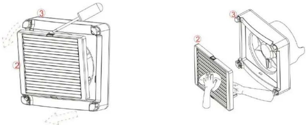
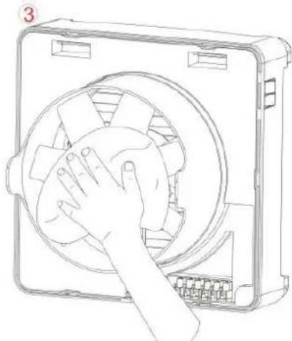
Clean the damper [2] grill with a dry cloth to remove dust and general dirt. Carefully remount it in its housing until you hear a "click" from the fastening of the teeth. Clean the main unit [3] impeller's blades with a dry cloth.
natural_image
Line drawing of a hand cleaning a circular component inside a rectangular housing (no text or symbols)4) PUTTING THE PRODUCT BACK IN SERVICE AFTER CLEANING
Remount the main unit (3) together with the damper (2) and embellisher cover (1) on the wall attachment (4i).
Attention: If you are cleaning several units at the same time, remount each main unit in the location you removed it from in order to avoid communication problems between master units and slave units.
Simply reinstall the main wall unit and power up the product by turning it on with the master switch.
Once you have put the main unit back in its wall housing, turn the product on with the master switch, to reset the cleaning counter it is necessary to use the remote control (execution of the reset after filter cleaning is included in the remote control instruction manual).
INSTRUCTIONS FOR CORRECT OPERATION
RESPIRO 100/RESPIRO 150
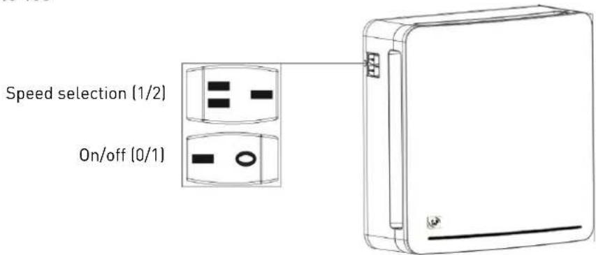
1. Turn-on
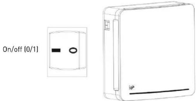
Once the product has been installed by qualified staff, turn it on by actuating the "0/1" switch on the side of the main unit. Make sure that the indicator light is on.
Once the damper is open the product starts working normally with the 70 seconds air intake and 70 seconds air extraction cycle.
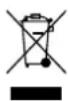
2. Speed selection
It is possible to increase or decrease the air exchange flow by means of the "1/2" switch on the side of the product.
Select speed 1 for a more silent air exchange.
Select speed 2 for a faster air exchange.
3. Wall commands
If during the installation carried out by qualified staff, the "on/off" and "speed selection" controls are remounted on the wall, make sure that the controls on the product are both positioned at "1".
The instructions for the commands remounted on the wall are the same as those of the aforementioned product.
4. Turn-off
Position the "0/1" switch on the side of the unit to "0".
If the controls have been carried to the wall, position the wall-mounted switch to "0". Keep the "on/off" switch on the side of the unit on "1".
RESPIRO 100 RD/RESPIRO 150 RD
If you only have one unit, access the product using the "0/1" switch and then wait for the correct configuration. After the red and white configuration pulse, the machine will start in the "AUTOMATIC" function.
If you have more than one unit, see the paragraph "MASTER-SLAVE PRODUCTS CONFIGURATION".
Attention: When first turned on the product executes the auto-calibration of the hygrostat. It is possible that during this phase the "EXTRACTION" function will be activated to bring the room's humidity below the level required for this auto-calibration.
PROBLEMS ENCOUNTERED
'S&P's official service network provides full technical assistance. If you note any anomaly in the device's operation, please contact one of the above departments, who will be delighted to help you. Any handling not strictly necessary for the installation of the device, executed by parties other than official S&P services, will force us to cancel the guarantee.
For any questions about S&P's products, please contact the Assistance Department.
TECHNICAL ASSISTANCE
If the product fails to turn on or it operates abnormally or is abnormally noisy, disconnect the product from the power by positioning the "0/1" switch on the side of the main unit to "0". Contact your dealer immediately and request technical assistance from our qualified staff.
REMOVAL FROM SERVICE, DISPOSAL AND RECYCLING
EU regulations and our commitment to future generations oblige us to recycle used materials; please remember to dispose of all unwanted packaging materials at the appropriate recycling points, and to drop off obsolete equipment at the nearest waste management point.
S&P reserves the right to modify the product without prior notification.
ITALIANO
RACCOMANDAZIONI IMPORTANTI
Contenuto
natural_image
Technical line drawing of a device casing with a circular center and mounting brackets, set against a brick wall background (no text or symbols)natural_image
Top-down schematic of a device casing with a circular center and red control buttons, set against a tiled wall (no text or symbols)natural_image
Technical line drawing of a mechanical housing component, showing front and side views with no text or symbolsTELECOMANDO (VERSIONE RD)
natural_image
Line drawing of a hand holding a rectangular electronic device with buttons (no text or symbols)LISTA COMANDI
natural_image
Line drawings of a vacuum cleaner and a shower faucet with labeled parts (no text or symbols present)flowchart
graph TD
    A["Raw Material 8"] --> B["Intermediate Stage 7"]
    B --> C["Final Disposal"]
    C --> D["Recycling to Disposal"]
natural_image
Line drawing of a vacuum cleaner with a coiled hose and bulb (no text or symbols)natural_image
Three circular diagrams showing different material or device configurations: a circular cross-section, a hexagonal grid pattern, and a rectangular cross-section with a black vertical line (no text or symbols)3) PULIZIA SERRANDA E VENTOLA
natural_image
Line drawing of a hand cleaning a circular fan inside a rectangular device (no text or symbols)4) RIPRISTINO DEL PRODOTTO DOPO LA PULIZIA
natural_image
Line drawing of a rectangular electronic device with a handle and control panel (no text or symbols)RECOMMANDATIONS IMPORTANTES
FR
natural_image
Diagram of a device casing with a circular center and labeled EXT (no text or symbols on the diagram itself)natural_image
Top-down schematic of a device casing with a circular center and red control buttons, set against a brick wall background (no text or symbols)natural_image
Technical line drawing of a mechanical housing component, showing front and side views with no text or symbolsTÉLÉCOMMANDE (VERSION RD)
RETRAIT DE L'ÉTIQUETTE DE PROTECTION
natural_image
Line drawing of a hand holding an open remote control device (no text or symbols)LISTE DES COMMANDES
HI - HI - H2 - H2 - H3 - H3
RÉINITIALISATION DU PRODUIT
natural_image
Line drawings of a vacuum cleaner and a shower faucet (no text or symbols)flowchart
graph TD
    A["Raw Material 8"] --> B["Intermediate Stage 7"]
    B --> C["Final Disposal"]
    C --> D["Recycling to Disposal"]
natural_image
Line drawing of a vacuum cleaner with a coiled hose and attached cylindrical component (no text or symbols)natural_image
Line drawing of a hand cleaning a circular device with a fan (no text or symbols)4) REMETTRE LE PRODUIT EN SERVICE APRÈS NETTOYAGE
Produktbeschreibung
natural_image
Technical line drawing of a device casing with a circular center and mounting brackets, set against a brick wall background (no text or symbols)natural_image
Diagram of a washing machine with a circular chamber and red indicator lights, set against a brick wall background (no text or symbols)natural_image
Technical line drawing of a mechanical housing component, showing front and side views with no text or symbolsFERNBEDIENUNG (RD-VERSION)
natural_image
Line drawing of a hand holding a remote control device (no text or symbols)BEFEHLE
natural_image
Line drawings of a vacuum cleaner and a shower faucet with labeled parts (no text or symbols present)natural_image
Line drawing of a vacuum cleaner with a coiled hose and attached cylindrical component (no text or symbols)natural_image
Line drawing of a hand cleaning a circular fan inside a rectangular device (no text or symbols)natural_image
Line drawing of a device with two electrical connectors and a separate inset showing internal components (no text or symbols)1. Einschalten
natural_image
Line drawing of a rectangular electronic device with a handle and base (no text or symbols)
natural_image
Diagram of a device casing with a circular center and mounting brackets, set against a brick wall background (no text or symbols)natural_image
Diagram of a washing machine with a central circular chamber and red buttons, set against a brick wall background (no text or symbols)natural_image
Technical line drawing of a mechanical housing component, showing front and side views with no text or symbolsAFSTANDSBEDIENING (RD VERSIE)
natural_image
Line drawing of a hand holding a rectangular electronic device with buttons, no text or symbols presentLIJST VAN COMMANDO'S
HI - HI - H2 - H2 - H3 - H3
PRODUCT RESETTEN
natural_image
Line drawings of a vacuum cleaner and a shower faucet with labeled parts (no text or symbols present)natural_image
Line drawing of a vacuum cleaner with a coiled hose and attached cylindrical component (no text or symbols)natural_image
Line drawing of a hand cleaning a circular fan inside a rectangular device (no text or symbols)4) HET PRODUCT OPNIEUW IN WERKING STELLEN NA HET SCHOONMAKEN
INSTRUCTIES VOOR CORRECTE WERKING
RESPIRO 100/RESPIRO 150
Описание продукта
natural_image
Top-down schematic of a washing machine with a circular chamber and mounting brackets, set against a tiled wall (no text or symbols)natural_image
Technical line drawing of a mechanical housing component, showing front and side views with no text or symbolsnatural_image
Line drawing of a hand holding a smartphone with a small circular button (no text or symbols)ФУНКЦИИ КНОПОК
HI - HI - H2 - H2 - H3 - H3
СБРОС НАСТРОЕК (RESET)
natural_image
Line drawings of a vacuum cleaner and a shower shower device (no text or symbols)flowchart
graph TD
    A["Stage 7: Plastic Container"] --> B["Stage 8: Plastic Box"]
    B --> C["Stage 8: Plastic Box"]
    C --> D["Stage 8: Plastic Box"]
    D --> E["Recycle to Basket"]
natural_image
Line drawing of a vacuum cleaner with attached hose and bulb (no text or symbols)natural_image
Three circular diagrams showing different material patterns: a textured circular layer, a hexagonal grid, and a solid black vertical line (no text or symbols)natural_image
Line drawing of a hand cleaning a circular fan inside a rectangular device (no text or symbols)natural_image
Line drawing of a rectangular electronic device with a label 'E' on the left side (no text or symbols on the device itself)Ürünün tanımı
natural_image
Technical diagram of a device casing with a circular component, mounted on a brick wall (no text or symbols)natural_image
Diagram of a device casing with a circular center and labeled components, set against a brick wall background (no readable text or symbols)natural_image
Technical line drawing of a mechanical housing component, showing front and side views with no text or symbolsnatural_image
Line drawing of a hand holding a mobile phone with a scroll (no text or symbols)KOMUT LISTESİ
natural_image
Line drawings of a vacuum cleaner and a showerhead device (no text or symbols)natural_image
Line drawing of a vacuum cleaner with a coiled hose and connector (no text or symbols)natural_image
Line drawing of a hand cleaning a circular fan inside a rectangular device (no text or symbols)4) TEMİZLİK SONRASI ÜRÜNÜN TEKRAR HİZMETE ALINMASI
1. Açma
Fax :+34 93.571.93.01
www.solerpalau.com
ithalata Firma
S&P AFS HAVA. SISTEMLERÍ A.S
Fuar Caddesi No: 8 Haramidere
natural_image
Top-down schematic of a device casing with a circular chamber and mounting brackets, set against a brick wall background (no text or symbols)natural_image
Diagram of a device casing with a circular center and red indicator lights, set against a brick wall background (no text or symbols)natural_image
Technical line drawing of a mechanical housing component, showing front and side views with no text or symbolsFJÄRRKONTROLL (RD-VERSION)
BORTTAGNING AV SKYDDSETIKET
natural_image
Line drawing of a hand holding a handheld electronic device (no text or symbols visible)LISTA KOMMANDON
HI - HI - H2 - H2 - H3 - H3
ÅTERSTÄLLNING AV PRODUKTEN
natural_image
Line drawings of a vacuum cleaner and a shower faucet with labeled parts (no text or symbols present)flowchart
graph TD
    A["Stage 7: Plastic Container"] --> B["Stage 8: Plastic Box"]
    B --> C["Stage 8: Plastic Box with Cover"]
    C --> D["Stage 8: Plastic Box with Basket"]
    D --> E["Recycle to Basket"]
natural_image
Line drawing of a handheld vacuum cleaner with a coiled hose and bulb (no text or symbols)natural_image
Line drawing of a hand cleaning a circular fan inside a rectangular device (no text or symbols)4) ATT STARTA PRODUKTEN EFTER RENGÖRING

Tuotteen kuvaus
natural_image
Diagram of a device casing with a circular center and mounting brackets, set against a brick wall background (no text or symbols)natural_image
Diagram of a device casing with a circular center and red control buttons, set against a brick wall background (no text or symbols)
KAUKOSÄÄDIN (RD-VERSIO)
SUOJAKALVON POISTAMINEN
natural_image
Line drawing of a hand holding a smartphone with an arrow pointing to it (no text or symbols)LUETTELO KOMENTOT