Nordic Evolution 90 - Fan Thermex - Free user manual and instructions
Find the device manual for free Nordic Evolution 90 Thermex in PDF.

| Product type | Reversible ceiling fan with infrared remote control |
| Model | Nordic Evolution 90 |
| Brand | Thermex |
| Blade diameter | 90 cm |
| Estimated weight | Approximately 5 kg |
| Power supply | 220-240 V ~ 50 Hz |
| Estimated power | Approximately 50-70 W |
| Remote control | Infrared, range 13 m, 2 AA 1.5 V batteries (not included) |
| Speeds | 5 adjustable speeds |
| Reversibility | Yes, summer/winter mode |
| Timer | 1 hour (adjustable via remote control) |
| Lighting | Compatible light fixture (optional, controlled by remote) |
| Installation | By a qualified professional, suspension rod max 500 mm |
| Maintenance | Clean with a soft dry cloth; do not use abrasive products |
| Safety | Disconnect before cleaning; do not immerse; cut power in case of malfunction |
| Protection | Do not use in the presence of flammable vapors |
| Warranty | 2 years against manufacturing defects |
| Spare parts | Use exclusively original Vortice parts |
| Repairability | Contact an authorized after-sales service |
Frequently Asked Questions - Nordic Evolution 90 Thermex
User questions about Nordic Evolution 90 Thermex
0 question about this device. Answer the ones you know or ask your own.
Ask a new question about this device
Download the instructions for your Fan in PDF format for free! Find your manual Nordic Evolution 90 - Thermex and take your electronic device back in hand. On this page are published all the documents necessary for the use of your device. Nordic Evolution 90 by Thermex.
USER MANUAL Nordic Evolution 90 Thermex
natural_image
Abstract black and white spiral design on dark background (no text or symbols)
TELENORDIK 5TR
CE
natural_image
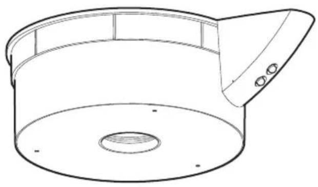
Line drawing of a cylindrical container with a lid and vent, showing internal structure (no text or symbols)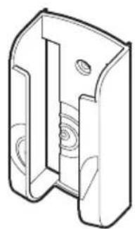
natural_image
Technical line drawing of a mechanical bracket or housing component (no text or symbols)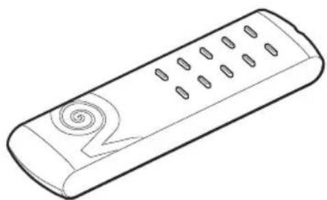
natural_image
Line drawing of a remote control device with scroll button (no text or symbols)©OD. 5471.084.152
11/12/2014
Read these instructions carefully before installing and connecting this appliance. Vortice cannot assume any responsibility for damage to property or personal injury resulting from failure to abide by the instructions given in this manual. Following these instructions will ensure a long service life and overall electrical and mechanical reliability. Always keep this instruction booklet in a safe place.
Table of Contents EN
Typical applications....4
Description and operation....8
Warning - Caution....8
Installation 8
Use applicable to all models ..... 9
Maintenance / Cleaning 10
Installation drawings 32
Index FR
APPLICATIONS TYPIQUES
natural_image
Line drawing of a hand holding a handheld device extending from a three-blade fan to a ceiling fan (no text or symbols)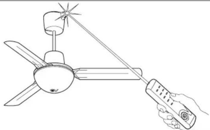
natural_image
Line drawing of a hand holding a remote control with a three-blade fan and star-shaped head (no text or symbols)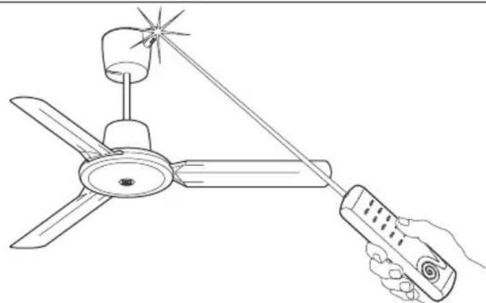
natural_image
Line drawing of a hand holding a handheld air conditioner next to a three-blade fan (no text or symbols)Description and operation
TELENORDIK 5TR is an infrared remote control unit with timer, for remote control of all Vortice reversible ceiling fans, with and without light.
The appliance comprises two parts, a receiver and a transmitter. TELENORDIK 5TR can be used: to operate the fan at 5 different speeds, to reverse the fan, and to turn the light on / off in versions fitted with a light. In addition, the timer incorporated in TELENORDIK 5TR can operate the fan for one hour at the selected speed and in the selected direction.

Warning! This symbol indicates precautions that must be taken to avoid personal injury
- Do not use this appliance for purposes other than the proper purposes described in this manual.
- After removing the appliance from its packaging, ensure that it is complete and undamaged. If in doubt contact a professionally qualified electrician or Vortice. Do not leave packaging within the reach of children or infirm persons.
- Certain fundamental rules must be observed when using any electrical appliance, including: a) never touch appliances with wet or damp hands; b) never touch appliances while barefoot; c) never allow children or infirm persons to operate appliances unattended.
- Do not us the appliance where flammable vapours are present (spirit, insecticides, petrol, etc.)
- Store the appliance out of reach of children and infirm persons after disconnecting it from the power supply.
- Any modification made to the appliance automatically invalidates the warranty and absolves the manufacturer from all liability.

Caution! This symbol indicates precautions that must be taken to avoid damage to the appliance
- Do not make modifications of any kind to this appliance.
- Do not expose this appliance to the weather (rain, sun, etc.).
- Do not immerse the appliance or any of its parts in water or other liquids.
- Regularly inspect the appliance for visible defects. If any faults are found, do not operate the appliance; contact Vortice* immediately.
- If the appliance does not function correctly or develops a fault, contact Vortice* immediately. Ensure that only genuine original Vortice spares are used for any repairs.
- Should the appliance be dropped or suffer a heavy blow, have it checked by Vortice* immediately.
-
The appliance must be installed by a professionally qualified electrician.
-
The electrical system to which the appliance is connected must conform to applicable standards.
- The appliance must be connected to an efficient earthing system in accordance with applicable electrical safety standards. If in doubt, ask a qualified electrician to check your system.
- The electrical power supply/socket to which the appliance is to be connected must be able to provide the maximum electrical power required by the appliance. If it does not do so, arrange for a qualified electrician to make the necessary modifications.
- Use a multi-polar switch with a minimum contact gap of 3 mm or more to install the appliance.
- Switch off the appliance at the installation's main switch: a) if the appliance does not function correctly; b) before cleaning the outside of the appliance, c) if the appliance is not to be used for any length of time.
- The internal connection cable in this appliance must never be replaced by the user, but only by a qualified electrician.
- Remove the batteries from the transmitter and dispose of them at a designated battery collection point before scrapping the transmitter.
Installation (see drawings on page 32)
The receiver is set up to be fitted on all Vortice reversible ceiling fans with a max. rod length of 500 mm. If it is fitted on a longer rod, replace the six-pole cable provided with another of the same type and a suitable length.
If it is installed on a shorter rod, adapt the length of the cable by cutting it at the free end that is not connected to the receiver.
FITTING ON REVERSIBLE CEILING FANS WITHOUT A LIGHT TO BE FITTED
1) Insert the remote control receiver A and the cover G into the fan extension rod (Fig.2).
2) Insert the connection cable C, already wired to the receiver, into the pipe until it comes out of the hole B. If TELENORDIK 5TR is installed on a new ceiling fan, do not fit the cable raceway that, according to the fan instruction booklet, should be fitted in hole B (Fig. 3); if TELENORDIK 5TR is installed on a ceiling fan that is already in place, remove the cable raceway fitted in hole B (Fig. 3).
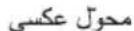
3) Connect the connection cable C to the fan terminal board, as indicated: 1 = blue, 2 = grey, ♣ = yellow-green, 5 = white.
4) Connect the power supply wires to terminal board E in accordance with the L, N, ⏻ symbols shown on the base of the receiver near the terminal board itself (Fig. 4).
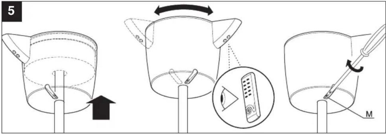
5) Insert the receiver, together with the cover that holds it, against the ceiling or near it, and fasten screw M without tightening it too much (Fig. 5).
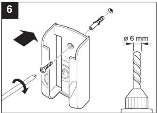
6) The remote control transmitter support can be fastened to the wall by drilling a ∅ 6 mm hole and inserting the wall plug provided (Fig.6).
FITTING ON REVERSIBLE CEILING FANS WITH A LIGHT TO BE FITTED
1) Insert the remote control receiver A and the cover G into the fan extension rod (Fig. 2).
2) Insert the connection cable C, already wired to the receiver, into the pipe until it comes out of the hole B. If TELENORDIK 5TR is installed on a new ceiling fan, do not fit the cable raceway that, according to the fan instruction booklet, should be fitted in hole B (Fig. 3); if TELENORDIK 5TR is installed on a ceiling fan that is already in place, remove the cable raceway fitted in hole B (Fig.3).
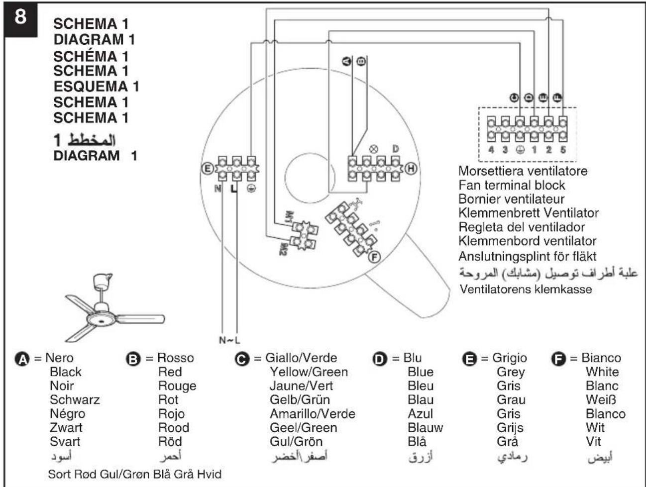
3) Disconnect the red and black wires from terminal board H and (Diagram 1 – Fig.8) and connect them to the terminals marked (General diagram - Fig.9).
4) Connect the connection cable C to the fan terminal board, as indicated: 1 = blue, 2 = grey, ⏻ = yellow-green, 3 = red, 4 = black, 5 = white.
5) Complete electrical connections, selecting one of the diagrams illustrated below, and taking great care to follow the instructions provided:
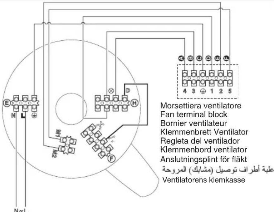
Diagram A Fig. 10: Light turned on and off using the remote control transmitter only
A) Connect the power supply wires to terminal board E in accordance with the L, N, ⊕ symbols shown on the base of the receiver near the terminal board itself.
B) Connect the terminal marked D on terminal board H to the terminal marked on terminal board F using the cable provided in the bag of accessories (ref. brown cable end terminal).
Diagram B: Light turned on and off using the remote control transmitter and a switch on the wall of the room (existing system with two switches) The remote control receiver must be connected in place of the switch, to the central terminal of which one of the two conductors for the existing lamp is connected.
A) Disconnect the lamp or lighting unit W fitted in the room at points 4 and 5 (Diagram B - Fig.11).
B) Connect the power supply wires to terminal board E in accordance with the L, N, ⊕ symbols shown on the base of the receiver near the terminal board itself (Diagram B1 - Fig.12).
C) Disconnect the wires connected to points 1 and 3 from the switch V, extend them, and connect them to the terminals marked ↗ on terminal board F (Diagram B1 - Fig.12).
Diagram C: Light turned on and off using the remote control transmitter and a switch and one or more inverters on the wall of the room (existing system with two switches and one or more inverters)
The remote control receiver must be connected in place of the switch, to the central terminal of which one of the two conductors for the existing lamp is connected.
A) Disconnect the lamp or lighting unit W fitted in the room at points 4 and 5 (Diagram C - Fig.13).
B) Connect the power supply wires to terminal board E in accordance with the L, N, symbols shown
on the base of the receiver near the terminal board itself (Diagram C1 - Fig.14).
C) Disconnect the wires connected to points 1 and 3 from the switch V, extend them, and connect them to the terminals marked * on terminal board F (Diagram C1 - Fig.14).
Diagram D: Light turned on and off using the remote control transmitter and one or more buttons (existing system)
A) Disconnect the lamp or lighting unit W fitted in the room at points 4 and 5 (Diagram D - Fig.15).
B) Disconnect all the system buttons and relays from the mains supply at points 6, 7 and 8 (Diagram D - Fig. 15).
C) Connect the power supply wires to terminal board E in accordance with the L, N, ⊕ symbols shown on the base of the receiver near the terminal board itself (Diagram D1 - Fig.16).
D) Connect the terminal marked D on terminal board H to the terminal marked on terminal board F using the cable provided in the bag of accessories (ref. brown end terminal - Diagram D1 - Fig.16).
E) Connect all the buttons in the system in parallel to the terminals marked ☐ on terminal board F (Diagram D1 - Fig.16).
Diagram D1: Light turned on and off using the remote control transmitter and one or more buttons (new system)
A) Connect the power supply wires to terminal board E in accordance with the L, N, symbols shown on the base of the receiver near the terminal board itself (Diagram D1 - Fig.16).
B) Connect the terminal marked D on terminal board H to the terminal marked on terminal board F using the cable provided in the bag of accessories (ref. brown cable end terminal - Diagram D1 -Fig.16).
C) Connect all the buttons in the system in parallel to the terminals marked (Diagram D1 -Fig.16).
6) Insert the receiver, together with the cover that holds it, against the ceiling or near it, and fasten screw M without tightening it too much (Fig. 5).
7) The remote control transmitter support can be fastened to the wall by drilling a 6 mm hole and inserting the wall plug provided (Fig. 6).
Warning
If the fan control box was fitted originally, it must be removed when the remote control is installed; it will therefore be necessary to restore the line connection. The receiver should be fixed so that the two LED indicators are visible from the area in which the transmitter is to be used most frequently.
Use applicable to all models
1) Once the electrical connections have been made and the fan has been installed on the ceiling, close the multi-pole switch: a first red LED will illuminate to indicate that the remote control is receiving power.
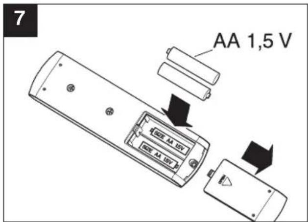
2) Insert two AA 1.5V alkaline type batteries in the Transmitter, with the poles positioned as indicated (Fig.7).
3) Test the ceiling fan functions, by pressing buttons (1 - 2 - 3 - 4 - 5) on the remote control transmitter, according to the speed, and test the reversing function using the buttons (the red indicator light will flash and a beep will sound to confirm that the command has been received).
4) Test the fan light on/off function (if there is one), by pressing on the transmitter.
5) Press "0" on the transmitter to stop the fan; if necessary, press ✝ again to turn off the fan light. Check any other switches, inverters and buttons, to ensure the whole system is working properly.
Timer function
This remote control is equipped with a timer function, allowing the fan to be operated at the speed and in the direction selected for approximately 1 hour.
To start the timer function, turn the fan on and press ⏻. The green LED on the receiver will light up to indicate that the function has been activated. This green LED will remain lit while the timer is in operation (approx. 1 hour). After this it will go out. To start a new timer cycle, select the function again by pressing .
If desired, you can change fan speed and/or direction after the timer function has been started; this action will not affect the timer period, which will still be approximately 1 hour.
If you wish to stop the timer function before the end of the period set, simply press "0".
When the appliance is turned off by pressing "0", all functions except the light will be switched off.
The reception distance between transmitter and receiver (with fully charged batteries in the transmitter) is approximately 13 m.
When installing a number of fans with TELENORDIK 5TR, it is recommended that the appliances be fitted at least 3 m from each other.
Maintenance / Cleaning
Before carrying out any type of cleaning or maintenance operation, turn the appliance off at the main switch and, if equipped with a plug, unplug it from the power supply.
Do not use powders, abrasive substances, solvents or alcohol to clean the exposed surface of the appliance.
ANVENDELSE PÅ REVERSIBLE LOFTSVIFTER UDEN LYS
ANVENDELSE PÅ REVERSIBLE LOFTSVIFTER MED LYS
9
SCHEMA GENERALE
GENERAL DIAGRAM
SCHÉMA GÉNÉRAL
HAUPTSCHEMA
ESQUEMA GENERAL
ALGEMEEN SCHEMA
ALLMÄNT SCHEMA
المخط العام
GENERELT DIAGRAM
natural_image
Line drawings of two different types of ceiling fans with three blades and a central hub (no text or symbols)A

natural_image
Two identical line drawings of a three-bladed ceiling fan with a propeller, shown from different angles (no text or symbols)A

B
C
D
E
T = Deviatore
Switch
Déviateur
Wechselschalter
Desviador
Schakelaar
Strömbrytare
Omskifter Omskifter Eksisterende lampe i rummet
Lamp fitted in the room
natural_image
Line drawings of two different types of ceiling fans or blades, no text or symbols present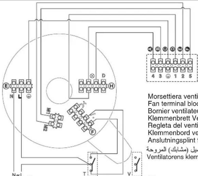
T = Deviatore
Switch
Déviateur
Wechselschalter
Desviador
Schakelaar
Strömbrytare
Omskifter Omskifter
T = Deviatore
Switch
Déviateur
Wechselschalter
Desviador
Schakelaar
Strömbrytare
V = Deviatore
Switch
Déviateur
Wechselschalter
Desviador
Schakelaar
Strömbrytare
Z = Invertitore
Inverter
Inverseur
Polumschalter
Inversor
Omschakelaar
Strömriktare
Lamp fitted in the room
natural_image
Line drawing of a two-tiered ceiling fan with three blades and a propeller (no text or symbols)
Lamp fitted in the room
Vortice S.p.A. reserves the right to make improvements to products at any time and without prior notice.
natural_image
Empty white rectangle with black border (no text or symbols)TIMBRO CENTRO ASSISTENZA
STAMP OF TECHNICAL ASSISTANCE CENTRE - CACHET SERVICE APRES-VENTE
C
natural_image
Empty white rectangle with black border (no text or symbols)TIMBRO CENTRO ASSISTENZA
STAMP OF TECHNICAL ASSISTANCE CENTRE - CACHET SERVICE APRES-VENTE
D
natural_image
Empty white rectangle with black border (no text or symbols)TIMBRO CENTRO ASSISTENZA
STAMP OF TECHNICAL ASSISTANCE CENTRE - CACHET SERVICE APRES-VENTE
UK AND IRELAND FRANCE CONDITIONS OF WARRANTY CONDITIONS DE GARANTIE
This guarantee is offered as an extra benefit and does not affect your legal rights. All electrical appliances produced by Vortice are guaranteed by the Company for two years against faulty material or workmanship. If any part is found to be defective in this way within the first twenty months four from the date of purchase or hire purchase agreement, we or our authorised service agents, will replace or at our option repair that part without any charge for materials or labour or transportation, provided that the appliance has been used only in accordance with the instructions provided with each appliance and has been not connected to an unsuitable electricity supply, or subjected to misuse, neglect or damage or modified or repaired by any person not authorised by us. The correct electricity supply voltage is shown on the rating plate attached to the appliance.
This guarantee is normally available only to the original purchaser of the appliance, but the Company will consider written applications for transfer. Should any defect arise in any Vortice product and a claim under guarantee become necessary, the appliance should be carefully packed and returned to your approved Vortice stockist. This portion of the guarantee should be attached to the appliance.
Send the guarantee in sealed envelope to: Vortice Limited Beeches House Eastern Avenue Burton on Trent DE13 0BB United King

I authorize Vortice Ltd. to include my personal details within their database, which they use, via a third party for the despatch of advertising material, at any time, in accordance with the regulations in force within my country. I can have access to my details and can request changes, or prohibit the usage of my details. This will be done by addressing my request directly to Vortice Limited Beeches House Eastern Avenue Burton on Trent DE13 0BB United Kingdom.
FRANCE
Please send the guarantee to the retailer's address in the country where the appliance has been purchased.

I authorize Vortice Elettrosociali S.p.A. and its local distributors to include my personal details within their database and they can use it through a third party for the despatch of advertising material. At any time, in accordance with the regulations in force within my country. I can have access to details and can ask to make changes, or prohibit the usage of my details. This will be done by addressing my request directly to the headquarters of the local distributor where the appliance has been bought.

I do not authorize (please tick if required).

I do not authorize (please tick if required).

GARANZIA - GUARANTEE - GARANTIE
DA CONSERVARE
TO BE RETAINED A CONSERVER

VORTICE
ANNI

YEARS
DATA
DATA - DATE
This warranty must be attached to the appliance should it need to be returned for servicing.
N.B. Guarantee is only valid if all details are completed correctly.
natural_image
Empty white square with black border (no text or symbols)SPEDITO IL
MAILING DATE - ENVOYÉ PAR LA POSTE LE
CONF.
COLL.
natural_image
Empty white rectangle with black border (no text or symbols)
GARANZIA - GUARANTEE - GARANTIE
natural_image
Empty white square with a thin black border (no text or symbols)DATI UTENTE / CUSTOMER DATA / COORDONNÉES DE L'UTILISATEUR
nome / name / nom
cognome / surname / prenom
via / street / rue
cap / post code / code postal
città / town
natural_image
Empty white rectangle with black border (no text or symbols)