WH20S - Heat pump LG - Free user manual and instructions
Find the device manual for free WH20S LG in PDF.
| Product Type | Heat pump for domestic hot water |
| Brand and model | LG WH20S |
| Tank capacity | 200 liters |
| Dimensions (L x H x D) | 580 x 1625 x 582 mm |
| Empty weight | 100 kg |
| Power supply | 230 V ~ 50 Hz, single-phase |
| Maximum total electric power | 2600 W |
| Heat pump power | 550 W |
| Heating element power | 2050 W |
| Water temperature setting range | 35 °C to 60 °C |
| Heat pump operating temperature range | -5 °C to 48 °C |
| Refrigerant | R134a, 0.65 kg |
| Maximum service pressure | 1 MPa |
| Corrosion protection | Impressed current cathodic protection (ICCP) |
| Internal tank protection | Ceramic coating |
| Protection rating | IPX1 |
| Operating modes | Heat pump, Auto, Turbo, Vacation, Anti-legionella |
| Connectivity | Wi-Fi (2.4 GHz), LG ThinQ app |
| Air filter maintenance | Clean when alarm appears; vacuum or warm water with mild detergent |
| Safety | T&P relief valve, ECO (temperature limiter), recommended RCD 30 mA |
| Spare parts and repairability | Parts list provided; repair by qualified technician only |
Frequently Asked Questions - WH20S LG
User questions about WH20S LG
0 question about this device. Answer the ones you know or ask your own.
Ask a new question about this device
Download the instructions for your Heat pump in PDF format for free! Find your manual WH20S - LG and take your electronic device back in hand. On this page are published all the documents necessary for the use of your device. WH20S by LG.
USER MANUAL WH20S LG
Read this owner's manual thoroughly before operating the appliance and keep it handy for reference at all times.
Original instruction
EN ENGLISH FR FRANÇAIS IT ITALIANO PL POLSKI
ES ESPAÑOL DE DEUSTSCH

MFL71409209 Rev.00_090823
CE UK CA
LG Electronics Inc. Single Point of Contact (EU/UK) : LG Electronics European Shared Service Center B.V. Krijgsman 1, 1186 DM Amstelveen, The Netherlands
www.lg.com
Copyright © 2023 LG Electronics Inc. All Rights Reserved.
TABLE OF CONTENTS
This manual may contain images or content different from the model you purchased. This manual is subject to revision by the manufacturer.
SAFETY INSTRUCTIONS....3
Safety Precaution....4
INSTALLATION 12
Parts and Functions ......12
Installation Tools....13
Accessories....13
Installation Instructions....14
Select the best Location....15
Unpacking and Removing Shipping Bolts 16
Thermal Expansion 16
Installing Drain Valve....16
Installing T&P Relief Valve 16
Installing Condensate Drain Lines ....18
Connecting the Water Supply....19
Making Electrical Connections 20
Safety Controls....21
Insulation Blanket Kits....21
Installation Checklist 22
OPERATION 23
Using Basic Control....23
SMART FUNCTIONS ......25
LG ThinQ Application 25
MAINTENANCE 27
Draining and Flushing the Water Heater 27
T&P Relief Valve Maintenance....28
Air Filter Maintenance ....28
Condensate Drain Maintenance....29
Shut-down for an Extended Period 29
TROUBLESHOOTING ....30
Before Calling for Service ....30
Error Code....32
Replacement Parts List 33
Technical specification ....35
SAFETY INSTRUCTIONS
EN
Your safety and the safety of others are very important.
We have provided many important safety messages in this manual and on your appliance. Always read and follow all safety messages.

This is the safety alert symbol.
This symbol alerts you to potential hazards that can kill or injure you and others. All safety messages will follow the safety alert symbol and either the word DANGER, WARNING or CAUTION. These words mean:

CAUTION
You may be slightly injured or cause damage to the product if you do not follow instructions.

WARNING
You may be killed or seriously injured if you do not follow instructions.

DANGER
This indicates that the failure to follow the instructions will cause serious injury or death.
All safety messages will tell you what the potential hazard is, tell you how to reduce the chance of injury, and tell you what may happen if the instructions are not followed.
! WARNING
To reduce the risk of explosion, fire, death, electric shock, injury or scalding to persons, instructions in this manual must be followed.
Be sure to fully understand the user's manual before you install and operate this appliance. If you have any difficulty in understanding or following the instructions in this manual, or have any questions, contact an authorized service center or the local electric utility.
Safety Precaution
Water Temperature Setting
! DANGER
Water temperature above 50 °C can cause severe burns instantly or death from scalding. Be sure to read and follow the warnings on the picture below.
DANGER

text_image
HOT BURNWater temperature over 50 °C can cause instant severe burns or even death from scalding.
Children, disabled and the elderly are at highest risk of scalding.
See owner's manual before setting temperature at water heater.
Feel water before bathing or showering.
Temperature limiting valves are available, see manual.
For determining the proper water temperature for your home, refer to the chart below.
| Temperature Time to Produce a Serious Burn | |
| 49 °C More than 5 minutes | |
| 52 °C 1 1⁄2 to 2 minutes | |
| 54 °C About 30 seconds | |
| 57 °C About 10 seconds | |
| 60 °C Less than 5 seconds | |
| 63 °C Less than 3 seconds | |
| 65 °C About 1 1⁄2 seconds | |
| dnoces 1 tuobAC °86 | |
NOTE
- To reduce point of use water temperature, Thermostatic Mixing Valves are recommended. These valves automatically mix hot and cold water in branch water lines. It is recommended to use a mixing valve.

DANGER
Households with the elderly, children, or people with disabilities may require a 48 °C or lower thermostat setting to prevent contact with “HOT” water.

DANGER
Higher water temperature increases the potential for Hot Water SCALDS
Water temperature in the heater is regulated by the buttons on display. The water temperature of this water heater is factory set to 50 °C to comply with safety regulations. For information about adjusting the water temperature, refer to the operation section in this manual.
Local Installation Regulations
This appliance must be installed accordance with instructions of this manual, national regulations, and any regulations issued by local authorities and public health bodies.
IMPORTANT SAFETY INSTRUCTIONS
! WARNING
To reduce the risk of explosion, fire, death, electric shock, scalding or injury to persons when using this product, follow basic precautions, including the following:
Children in the Household:
This appliance is not intended for use by persons (including children) with reduced physical, sensory or mental capabilities, or lack of experience and knowledge, unless they have been given supervision or instruction concerning use of the appliance by a person responsible for their safety. Children should be supervised to ensure that they do not play with the appliance.
Take care so that children may not step on the product. Otherwise, children may be seriously injured due to falling down.
For use in Europe:
This appliance can be used by children aged from 8 years and above and persons with reduced physical, sensory or mental capabilities or lack of experience and knowledge if they have been given supervision or instruction concerning use of the appliance in a safe way and understand the hazards involved. Children shall not play with the appliance. Cleaning and user maintenance shall not be made by children without supervision.
EN
Installation
- To reduce the risk of severe injury or death, follow all installation instructions.
- Be sure your appliance is properly installed in compliance with local codes and the provided installation instructions.
- Do not replace any part of your water heater and use only original accessories and spare part unless it is specifically recommended in this manual.
- Do not turn on the electrical power to water heater unless the tank is completely full of water.
- Never attempt to operate this appliance if it is damaged, malfunctioning, partially disassembled, or has missing or broken parts.
- When the product is soaked (flooded or submerged) in water, contact an Authorized Service Center for repair before using it again.
- Moving or installation of the appliance requires two or more people.
- Turn off the power by opening the circuit breaker or removing the fuses before installing.
- Even if the water heater thermostat is set to relatively low, hot water has the potential for scalding. To reduce the risk of scalding, thermostatic mixing valves are recommended.
- Keep packing materials out of the reach of children. Packaging material can be dangerous for children. There is a risk of suffocation.
- Destroy the carton, plastic bag, and other packing materials after the appliance is unpacked. Children might use them for play. Cartons covered with rugs, bedspreads, or plastic sheets can become airtight chambers.
- Connect to a properly rated, protected, and sized power circuit to avoid electrical overload.
EN
- This appliance must be positioned near to an electrical power supply. Use a power supply of 1.5 ~mm^2 or more in the nominal cross-sectional area
- Do not install the water heater on an unstable surface or in a place where there is danger of it falling.
- For installation, always contact the dealer or an Authorized Service Center. There is risk of fire, electric shock, explosion or injury.
- Do not install the water heater in a place where flammable liquids or gases such as gasoline, propane, paint thinner, etc., are stored.
• Always ground the product. There is risk of fire or electric shock
• Install the panel and the cover of the control box safety. - Do not touch heat exchanger fins with your bare hands. Otherwise, you may get a cut in your hands.
- Do not input air or gas into the system except with the specific refrigerant.
- Do not turn on the circuit breaker or power when covers are removed or opened.
- Make the connection securely so that screw in terminals may not be loosed when pulling cable.
- There is a risk of fire and explosion. Insert gas (nitrogen) should be used when you check plumbing leaks, cleaning or repairs of pipes etc. If you are using combustible gases including oxygen, product may have the risk of fires and explosions.
Operation
- Use this appliance only for its intended purpose.
- If the water heater has been subjected to fire, flood or physical damage, disconnect all power to water heater immediately, and DO NOT operate it again until it has been inspected by a qualifiedperson.
EN
- Donotturnonthewaterheaterunlesssthetankiscompletely fullofwater.
- Donotturnonthewaterheaterifcoldwatersupplyshut-off valveisclosed.
- Feelwaterbeforebathingorshowering.
- Evenat50 °C, hotwatercanscald.
- Do not block the inlet or outlet of air flow.
- Never touch, operate, or repair the water heater with wet hands.
- Do not leave flammable substances such as gasoline, benzene, or thinner near the water heater. (Do not install the unit in potentially explosive atmospheres.)
- Cut off the power supply if there is any noise, smell, or smoke coming from the water heater.
- Make sure that the power cable is neither dirty, loose, nor broken.
- Do not place any objects on the power cable.
- Do not modify or extend the power cable. Scratches or peeling insulation on the power cables may result in fire or electric shock, and should be replaced.
- The supply cord cannot be replaced. If the cord is damaged the appliance should be scrapped.
- Do not expose people, animals, or plants to the cold wind from the water heater for extended periods of time.
• Take care to ensure that power cable could not be pulled out or damaged during operation. There is risk of fire or electric shock.
- Do not touch refrigerant pipe, water pipe and any internal parts while the unit is operating or immediately after operation. There is risk of burns or frostbite, personal injury.
• Additional refrigerant injection is not possible.
Maintenance
- If the supply cord is damaged, it must be replaced by the manufacturer, its service agent or similarly qualified persons in order to avoid a hazard.
- Disconnect this appliance from the power supply before cleaning and attempting any user maintenance.
- Before draining water heater, turn off the power to product.
- Do not turn on the electrical power to the water heater unless the tank is completely full of water.
Technical Safety
• Installation or repairs made by unauthorized persons can pose hazards to you and others.
- The information contained in the manual is intended for use by a qualified service technician who is familiar with the safety procedures and equipped with the proper tools and test instruments.
- Failure to read and follow all instructions in this manual can result in equipment malfunction, property damage, personal injury and/or death.

CAUTION
To reduce the risk of minor injury to persons, malfunction, or damage to the product or property when using this product, follow basic precautions, including the following:
EN
Installation
• Install the product on a firm and level floor.
- Do not install the water heater in a place where leakage of the tank or connections will result in damage to the area adjacent to it or to lower floors of the structure. Where such areas cannot be avoided, it is recommended that a suitable drain pan, adequately drained, be installed under the water heater.
• Install the product so that the noise or hot wind from the appliance may not cause any damage to the neighbors. Otherwise, it may cause dispute with the neighbors.
• Install the drain hose properly for the smooth drainage of water condensation.
- Always inspect gas leakage after the installation and repair of product. Otherwise, it may cause the failure of product.
- In order to avoid a hazard due to inadvertent resetting of the thermal cut-out, this appliance must not be supplied through an external switching device, such as a timer, or connected to a circuit that is regularly switched on and off by the utility.
Operation
- Do not step on the product and do not put anything on it.
- Do not use this appliance if any part have been underwater. Immediately contact an Authorized Service Center for replace flooded water heater. Do not attempt to repair the unit. It must bereplaced.
- Turn off the power and water supply to water heater and drain water heater if the appliance is to be left for an extended period of time, such as during vacations.
INSTALLATION
EN
Parts and Functions

text_image
1 2 3 4 5 6 7 8 9 10 11 12 13 14 15 16 17 181 Top cover
2 Air intake vents
3 Junction box
4 Air filter
5 Front panel
6 Display decor / Control panel
7 ECO
8 Upper element cover
9 Front decor
10 Lower element cover
11 Heating element
12 Opening for drain valve
13 Water inlet
14 Opening for T&P relief valve
15 Water outlet
16 Condensate drain
17 Rear panel
18 Air outlet Vents
EN
Installation Tools
| Figure Name Figure Name | |||
 | Screw driver Teflon tape  | ||
 | Spanner Level 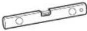 | ||
 | Multi-meter | ||
Accessories
Included Accessories:
| Figure Name Figure Name | |||
 | Drain valve T&P | relief  | |
Recommended Accessories:
| Figure Name Figure Name | |||
 | Drain pan |  | Thermal expansion tank |
 | Pressure reducing valve | 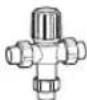 | Thermostatic mixing valve |
 | Dielectric Union | ||
EN
Installation Instructions

text_image
Ceiling 0.5 m Minimum clearance for installation or service. Air filter Display Primary condensate drain line (3/4" PVC) T&P relief valve and discharge line Secondary condensate drain line (1/2" PVC) Hot water outlet Flexible connection recommended Flexible connection recommended Open drain Drain valve Heat trap Min. 0.15 m Shut-off valve * Thermal expansion tank (if required) Cold water inlet* In closed system, connect a thermal expansion tank to cold water supply line. See "Thermal Expansion" Section (p.16).
* If copper piping is used, The dielectric unions(field supply) must be installed at the water connections.
EN
Select the best Location
NOTE
• Installation in a confined space without proper ventilation will lead to higher power consumption.
- Auxiliary drain pan MUST be installed in compliance with local codes.
Drain pan kits are available from the store where the water heater purchased, or any water heater distributor.
Drain pan should not obstruct cold water inlet or drain valve.
- Select space where has enough space for periodic servicing. The air filter, covers, and front panels can be removed to permit inspection and servicing.
- Take the weight of the water heater into account and select a place where the floor is strong enough to support the weight of full water heater.
- The water heater and water lines should be protected from freezing and high corrosive elements. Do not install water heater in outdoor or unprotected areas.
- Install the water heater close to the area of the greatest heater water demand and the center of plumbing system. Long uninsulated hot water lines can waste energy.
- Insufficient air exchange will result in increased energy consumption level.
- The installation site must be over 1 °C.
Ensure the water heater is horizontal using a spirit level.
Keep level parallel in installing the product. Otherwise, it may cause vibration or water leakage. It may cause injury or an accident.
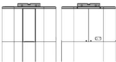
natural_image
Two identical line drawings of a vertical shelf or vent, showing top and bottom panels with no text or symbols.Minimum Clearances

text_image
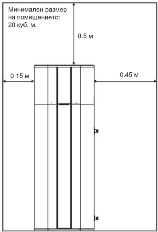
Minimum room size: 20 m³ 0.5 m 0.15 m 0.45 m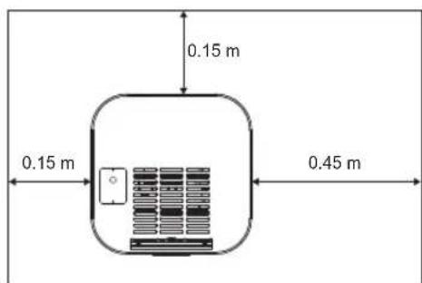
text_image
0.15 m 0.15 m 0.45 mNOTE
- For future service, a minimum 1 m clearance between any object and the left, right and back side is recommended.
EN
Unpacking and Removing Shipping Bolts
NOTE
- Accessories (drain valve and T&P relief valve) are attached on pallet. Keep it for installation.
Unpack all shipping materials from the water heater for proper operation and inspect it for shipping damage.
1 Remove carton and shipping materials.
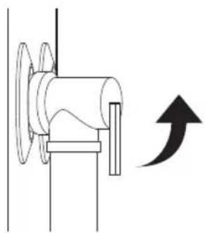
2 Remove the screws from the shipping brackets.

text_image
Accessories3 Pull out the shipping brackets.
text_image
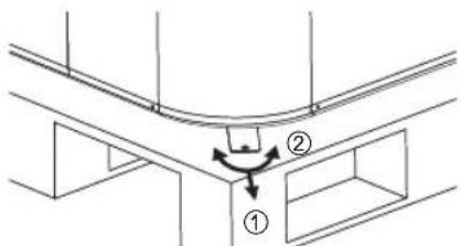
Technical diagram showing a structural component with labeled parts ① and ②, likely illustrating a mechanical or structural assembly.4 Slightly tip the water heater and carefully roll the water heater off the pallet.
Thermal Expansion
Determine if a check valve is present on the inlet water line. Check with your local water utility. A check valve located in cold water inlet line will create a "closed water system".
As water is heated, it creates an increase in pressure within the water system because the increased volume of water doesn't have a place to go.
Referred to as "thermal expansion", the rapid pressure increase can quickly reach the safety setting of the relief valve.
This will cause the relief valve to open during each heating cycle. We recommend installing an expansion tank to control thermal expansion.
Connect the thermal expansion tank to the cold water supply line (see Installation Instructions).
For additional information, contact installing contractor, plumbing inspector, or water supplier.
NOTE
- Drain valve and T&P relief valve is included in packing box of the water heater. They must be installed in the opening provided for this purpose.
Installing Drain Valve
1 Apply Teflon tape on the G end to prevent leaking.
natural_image
Technical line drawing of a mechanical valve assembly (no text or symbols)2 Install the drain valve in the opening marked "Drain Valve".
Installing T&P Relief Valve
Use T&P relief valve included in packing.
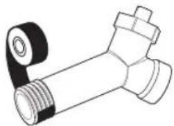
1 Apply Teflon tape on the G end to prevent leaking.

natural_image
Technical line drawing of a mechanical component with threaded shaft and handle (no text or symbols)2 Install the T&P relief valve in the opening marked T&P relief valve.
EN
Connecting T&P Relief Valve Discharge Pipe

WARNING
The pressure rating of the relief valve must not exceed 1 MPa, the maximum working pressure of the water heater as specified on the data plate.

WARNING
DO NOT connect any valve or other restriction to the T&P plumbing. DO NOT connect the T&P plumbing to the condensate plumbing. It must be directly piped to an adequate open drain.
Install T&P Relief Valve discharge pipe according to local codes and the following instructions.
- The inside diameter of the discharge pipe must be at least 3/4".
- The discharge pipe must be approved for hot water distribution and withstand 100 °C without distortion.
- The end of the discharge pipe should not be threaded or concealed and should be protected from freezing.
- Do not insert or install any type of valve, restriction, or reducer coupling in the discharge pipe.
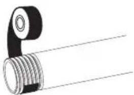
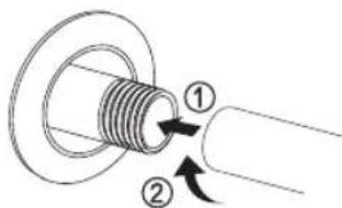
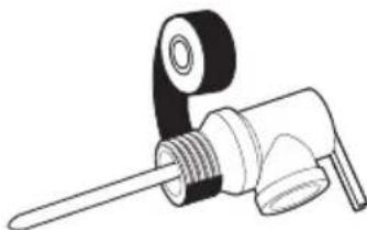
1 Apply Teflon tape on the G end to prevent leaking.
natural_image
Pure mechanical component diagram showing a threaded pipe joint with a circular head (no text or symbols)2 Attach the discharge pipe to outlet of the T&P relief valve. The discharge pipe must pitch downward from the valve to allow complete drainage of both T&P relief valve and discharge pipe.

text_image
Technical diagram showing mechanical assembly with labeled parts and directional arrows indicating motion or force3 The end of the discharge pipe must be piped to an adequate open drain.

* The water may drip from the discharge pipe of the pressure-relief device and that this pipe must be left open to the atmosphere.
* The pressure-relief device is to be operated regularly to remove lime deposits and to verify that it is not blocked.
* A discharge pipe connected to the pressure-relief device is to be installed in a continuously downward direction and in a frost-free environment.
EN
Installing Condensate Drain Lines
NOTE
- Whenmakingdrainfittingconnectionstothe draintubing, DONOTovertighten.
Overtighteningfittingscouldcrackor damage the condensate drain pan.
- Condensate from this unit is not acidic.
The condensate drain lines and connections to the drain piping must meet state and local codes.
Do not reduce the drain line size to less than the condensate connection size provided.
Ensure that the condensate drain lines maintain a downward slope for proper drainage.
The drain line should be insulated to prevent condensation from forming on the outside of the drain line.
If no floor drain is available or the drain is above the level of the condensate line, then a common condensate pump with a capacity no less than 7.5 L per day must be installed.
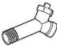
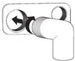
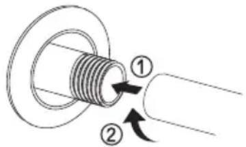
1 Apply Teflon tape on the G end to prevent leaking.

natural_image
Illustration of a mechanical connector with a curved handle and threaded shaft (no text or symbols)2 Attach elbow with 3/4" slip &3/4"G to the primary drain connection.
natural_image
Pure diagram of a pipe fitting with directional arrows indicating flow or movement (no text or symbols)3 Using an approved sealant, insert the PVC pipe into the female end. Condensate drain must be piped to an adequate drain.

natural_image
Simple line drawing of a T-shaped pipe fitting with an upward arrow pointing to a cylindrical component (no text or symbols)4 Using 1/2" PVC piping, an elbow with 1/2" slip & 1/2" G, and an approved sealant, attach the elbow to secondary drain connection and insert the PVC pipe into the female end.
EN
Connecting the Water Supply
NOTE
- DO NOT directly solder or braze to hot or cold water connections. If sweat connections are used, sweat tubing to adapter before installing the adapter to the hot or cold water connections on heater. Any heat applied to the water supply fittings will permanently damage the internal plastic lining in these ports.
* The maximum pressure in cold water supply line is 0.8 MPa. If the supply water is greater than 0.8 MPa, install a pressure reducing valve.
* Connect the water for filling or refilling the heating system as specified by EN1717/ EN 61770 to avoid contamination of drinking water by return flow.
| Maximum and minimum water operating temperatures (°C) | 35 / 62 |
| Maximum and minimum water operating pressure (MPa) | - / 0.8 |
Refer to "Installation Instructions" for suggested typical installation.
1 Check the type of water pipes in your home. Use fittings adequate for the type of pipe in your home.
If cooper piping used, The water heater should always be connected dielectric connections (filed supply) to avoid corrosion caused by electric currents common in copper water pipes.
For ease of disconnecting the water heater for service or replacement, the installation of unions is recommended on the water connections.
2 Apply Teflon tape on the G end to prevent leaking.

3 Connect cold and hot water supply using 3/4" G.
text_image
Diagram showing a mechanical component with labeled parts and directional arrows indicating motion or force.4 Install a shut-off valve in the cold water line near the water heater.
5 Install the insulation on the cold and hot water pipes. Insulating hot water pipe can increase energy efficiency.
To Fill the Water Heater

WARNING
Do not turn on the electrical power to water heater unless the tank is completely full of water. The water heater warranty does not cover damage or failure resulting from operation with empty or partially empty tank.
1 Make sure that the drain valve on water heater is completely closed.

natural_image
Pure mechanical diagram showing a valve and nut assembly without any text, numbers, or symbols2 Turn on the cold water supply
3 Open each hot water faucet slowly and allow the water to run until it flows with a full stream.
4 Let the water run full stream for a few minutes.
EN
Making Electrical Connections

WARNING
Disconnect all power before working on any electrical connections.

WARNING
The ground connection is mandatory.

WARNING
Never supply power to heating element directly. Upper and lower heating elements are installed on the product.(230 V, 2 kW)
NOTE
- All wiring must conform to European and national standards, and must be protected by a 30 mA RCD(Residual current device).
- Means for disconnection must be incorporated in the fixed wiring in accordance with the wiring rules.
The water heater must be permanently powered by electricity to ensure correct operation of the impressed current titanium anode (ICCP).
Do not turn on power until water heater is completely filled.
The appliance can only be connected and operated on a single-phase 230 V AC grid.
The electrical installation will include:
- The installation of a residual current device (RCD) having a rated residual operating current not exceeding 30 mA is advisable.
- The rating of the residual current device (RCD) to be installed
The supply cord cannot be disconnected from the product.
The supply cord cannot be replaced. If the cord is damaged the appliance should be scrapped.

CAUTION
In order to avoid a hazard due to inadvertent resetting of the thermal cut-out, this appliance must not be supplied through an external switching device, such as a timer, or connected to a circuit that is regularly switched on and off by the utility.

text_image
st be ng in ules. L1 L2 16 A30 mA BR BLSafety Controls

CAUTION
You must have a qualified person investigate the cause of the high temperature condition and take corrective action before placing the water heater in service again.
There is temperature limiting control(ECO) that is located above the upper heating element. If the water temperature becomes excessively high, the temperature limiting control(ECO) shuts off the power to the heating elements.
Once the control opens, it must be reset manually.
To reset temperature limiting control(ECO):
1 Turn off the power by opening the circuit breaker or removing the fuses.
2 Remove the front decor and upper element cover.
3 Press the red ECO RESET button.
Insulation Blanket Kits
External insulation blanket, available to the general public, for water heater is not necessary.
The manufacturer's warranty does not cover any damage or failure caused by installing or using any type of unauthorized energy-saving or other devices.
The manufacturer is not responsible for any injury or loss resulting from the use of such unauthorized devices.

CAUTION
If local codes require application of any external insulation blanket kit to water heater, it will require careful attention so as not to restrict the proper function and operation of this appliance:
- DO NOT block the air openings of the water heater.
- DO NOT cover or attempt to relocate the information or warning labels attached to the water heater.
- DO NOT cover the control panel, T&P relief valve, drain valve, and junction box.
- Inspect the blanket frequently.
Installation Checklist
Location
- Sufficient room for air exchange and periodic service.
- Floor is strong enough to support water heater.
- Indoor and protected from high corrosive elements.
- Close to the area of heater water demand.
□ Over 1 °C.
□ Area free of flammable liquids and gases.
Drain valve
- Drain valve properly installed.
T&P relief valve
☐ T&P relief valve properly installed.
- Discharge line maintains a downward slope and runs to adequate drain.
- Discharge pipe protected from freezing.
Condensate Drain
- Drain lines maintain a downward slope and run to adequate drain.
Water supply
□ Tank is completely full of water.
- Remove air from water heater and piping.
□ Water connections tight and free of leakage but DO NOT overtighten.
☐ If cooper piping used, connect the dielectric unions(field supply) to prevent corrosion.
- Flexible water connections recommended.
Wiring
- Power supply voltage agree with rating voltage on data plate.
- Proper size of branch circuit wire and fusing or circuit breaker.
□ Unit properly grounded.
OPERATION
EN
Using Basic Control
DISPLAY SCREEN
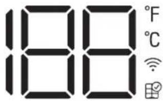
text_image
188 °F °C Wi-Fi AppHeat Pump
Auto
Turbo
Schedule
Vacation
Anti Legionella
2

Wi-Fi (3s)
^ F/ ^ C (3s)

Reset Filter (3s)

Water Temp (3s)
1
 Button Button | [KE57]Display Screen | Description |
 | Heat Pump | To select the heat pump mode. |
| Auto | To select the auto mode. | |
| Turbo | To select the turbo mode. | |
| Vacation | To select the vacation mode. | |
| - | Schedule | Set schedule mode only in LG ThinQ application. |
| - | Anti Legionella | To select the Anti Legionella mode. |
 | - | To set the desired water temperature. |
 |  | To adjust the desired water temperature. |
| Wi-Fi (3s) |  | To enable the Wi-Fi pairing. |
| Reset Filter (3s) | [2H44] | To reset the filter alarm. |
| °F/°C (3s) | ≈20 | To change unit between °F and °C. |
| Water Temp (3s) |  | To display the current water temperature for 5 seconds. |
Water Temperature Adjustment

DANGER
Higher water temperature increases the potential for Hot Water SCALDS.
The water temperature will be maintained according to the setting temperature on Display and can be adjusted from 35 °C to 60 °C.
1 Press or button to select the water temperature.
2 Press Set button to finish.
Operation Mode
- Press Mode button repeatedly to select the operating mode. The active mode is displayed on the display screen.
HEAT PUMP MODE
This mode minimizes power consumption by using only heat pump for heating, but has low recovery.
AUTO MODE
This mode is factory set mode for shipping. This mode provides relatively low power consumption and high recovery. This mode primary uses heat pump for heating. Heating elements will provide supplementary heating, if demand is more than the heat pump can keep up by itself.
TURBO MODE
This mode provides the highest recovery. This mode uses heat pump and heating element simultaneously.
VACATION MODE
This feature is recommended when the water heater is not in used for an extended period of time. In this mode, tank temperature will be maintained at about 20 °C to minimize energy consumption and prevent the water heater from freezing.
The vacation duration can be set or modified between 1 and 90 days via LG ThinQ app.
SCHEDULE MODE
This mode can set only in LG ThinQ application. You can escape this mode by pressing any button on the water heater.
ANTI-LEGIONELLA MODE
The water heater automatically performs the anti-legionella mode once a week. The water temperature will go up to 60 °C and stay for 1 hour. These temperature can scald, so we recommend you use a thermostatic mixing valves. (Default inactive)
Active / Inactive
- Press and hold Set button about 3 seconds to set the anti-legionella mode active or inactive Active: (Display Blinks "Anti-legionella" "Antilegionella" x 4) * Once a week operation Inactive: (Display Blinks "Anti-legionella" x 4)
Reset the Air Filter Alarm
The device will display alarm ( ☐ ) reminding you to check and clean the air filter periodically.
- Press and hold Set button about 3 seconds to reset the alarm.
Change Temperature Unit
Temperature unit display on Screen can be set to Fahrenheit or Celsius
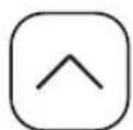
- Press and hold ⬆ button about 3 seconds to change temperature unit.
Current water Temperature
- Press and hold √ button about 3 seconds Display will show current water temperature of the tank for 5 seconds.
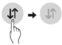
Wi-Fi PAIRING FUNCTION
Once it is connected to the internet through a home Wi-Fi network, you can control the appliance remotely with the application for the smart phone. See “SMART FUNCTION” section for details.
- Press and hold Mode button about 3 seconds.
is displayed on the display screen.
SMART FUNCTIONS
EN
LG ThinQ Application
This feature is only available on models with the 📄 or ThinQ logo.
The LG ThinQ application allows you to communicate with the appliance using a smartphone.
LG ThinQ Application Features
Communicate with the appliance from a smartphone using the convenient smart features.
Smart Diagnosis™
If you experience a problem while using the appliance, this smart diagnosis feature will help you diagnose the problem.
Settings
Allows you to set various options on the appliance and in the application.
NOTE
- If you change your wireless router, internet service provider, or password, delete the registered appliance from the LG ThinQ application and register it again.
- The application is subject to change for appliance improvement purposes without notice to users.
• Functions may vary by model.
Before Using LG ThinQ Application
1 Check the distance between the appliance and the wireless router (Wi-Fi network).
- If the distance between the appliance and the wireless router is too far, the signal strength becomes weak. It may take a long time to register or installation may fail.
2 Turn off the Mobile data or Cellular Data on your smartphone.
3 Connect your smartphone to the wireless router.

NOTE
- To verify the Wi-Fi connection, check that icon on the control panel is lit.
- The appliance supports 2.4 GHz Wi-Fi networks only. To check your network frequency, contact your Internet service provider or refer to your wireless router manual.
- LG ThinQ is not responsible for any network connection problems or any faults, malfunctions, or errors caused by network connection.
- If the appliance is having trouble connecting to the Wi-Fi network, it may be too far from the router.
Purchase a Wi-Fi repeater (range extender) to improve the Wi-Fi signal strength. - The Wi-Fi connection may not connect or may be interrupted because of the home network environment.
- The network connection may not work properly depending on the Internet service provider.
-
The surrounding wireless environment can make the wireless network service run slowly.
-
The appliance cannot be registered due to problems with the wireless signal transmission. Unplug the appliance and wait about a minute before trying again.
- If the firewall on your wireless router is enabled, disable the firewall or add an exception to it.
- The wireless network name (SSID) should be a combination of English letters and numbers. (Do not use special characters.)
- Smartphone user interface (UI) may vary depending on the mobile operating system (OS) and the manufacturer.
- If the security protocol of the router is set to WEP, you may fail to set up the network. Please change it to other security protocols (WPA2 is recommended) and register the product again.
Installing the LG ThinQ Application
Search for the LG ThinQ application from the Google Play Store or Apple App Store on a smartphone. Follow instructions to download and install the application.
Smart Diagnosis™
Use this feature to help you diagnose and solve problems with your appliance.
NOTE
- For reasons not attributable to LGE's negligence, the service may not operate due to external factors such as, but not limited to, Wi-Fi unavailability, Wi-Fi disconnection, local app store policy, or app unavailability.
- The feature may be subject to change without prior notice and may have a different form depending on where you are located.
Using LG ThinQ to Diagnose Issues
If you experience a problem with your Wi-Fi equipped appliance, it can transmit troubleshooting data to a smartphone using the LG ThinQ application.
- Launch the LG ThinQ application and select the Smart Diagnosis™ feature in the menu. Follow the instructions provided in the LG ThinQ application.
Open Source Software Notice Information
To obtain the source code that is contained in this product, under GPL, LGPL, MPL, and other open source licenses that have the obligation to disclose source code, and to access all referred license terms, copyright notices and other relevant documents, please visit https://opensource.lge.com.
LG Electronics will also provide open source code to you on CD-ROM for a charge covering the cost of performing such distribution (such as the cost of media, shipping, and handling) upon email request to opensource@lge.com.
This offer is valid to anyone in receipt of this information for a period of three years after our last shipment of this product.
MAINTENANCE
EN

WARNING
Turn off the power by opening the circuit breaker or removing the fuses before you perform any maintenance; otherwise it may cause electrical shock resulting in severe injury or death.
Before you perform any maintenance, turn off the power by opening the circuit breaker as below

Clean and check the product regularly to maintain optimal performance and to prevent possible break down. If you have difficulty to perform these routine maintenance tasks yourself, contact a qualified person.
Draining and Flushing the Water Heater
Minerals contained in tap water can form lime deposits. Therefore, it is not uncommon that lime deposits accumulate in the water heater's tank. The amount of lime deposits depends on water hardness, the temperature settings, and other variables.
1 Turn off the power by opening the circuit breaker or removing the fuses.
2 Connect a garden hose to the drain valve and place the and of the hose in a suitable drain.
3 Turn off the cold water supply valve.
4 Open the drain valve. (Open a hot water faucet or lift the handle on the T&P relief valve to help the water drain faster.)
5 Once the tank is empty, flush the tank by opening the cold water supply valve.
6 Allow the water run until no more sediment drains from the tank and water runs clear.
7 Close the drain valve and open the hot water faucet. Fill the tank by opening the cold water valve.
EN
T&P Relief Valve Maintenance
! DANGER
Before manually operating the relief valve, make sure it will discharge in a safe place. If water does not flow freely from the end of the discharge pipe, turn off the power to water heater and call a qualified person.
At least annually, lift and release the lever handle on water heater to ensure the waterways are clear and the valve operates freely.
natural_image
Pure mechanical diagram showing a shaft and housing assembly with an upward arrow, no text or symbols present.Air Filter Maintenance
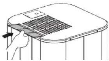
Clean the air filters when "Air filter check (☐)" alarm appears on the display.
NOTE
- The air filter can be broken when it is bended.
- When the air filter is not assembled correctly, dust and other substance come into the unit.
1 Turn off the power by opening the circuit breaker or removing the fuses.
2 Hold the knobs of the air filter, pull it and remove it from the top cover.

natural_image
Diagram of a hand pressing down on a device with a handle, showing internal structure (no text or symbols)3 Clean the filter with a vacuum cleaner or with lukewarm water with neutral detergent.
4 Dry the filter in the shade.
5 Insert the air filter into the top cover.
natural_image
Diagram of a hand pressing down on a device with a grid-like panel (no text or symbols)6 Check the top cover for correct assembly of the air filter.
EN
Condensate Drain Maintenance
1 Remove the condensate drain lines and connections.

text_image
Diagram showing a pipe fitting with numbered components and directional arrows indicating flow or movement.Shut-down for an Extended Period
If the water heater will not be used for an extended period of time, turn off the power and water supply to water heater and drain water heater to conserve energy and prevent a build-up of dangerous hydrogen gas.
The water heater and piping should be drained if they might be subjected to freezing temperature.
After a long shutdown period, the water heater's operation and controls should be checked by qualified service personnel. Make certain the water heater is completely filled again before placing it in operation.
2 Pull the front decor first, and then remove the top cover. Lift the front panel out, then slightly lift the rear panel and remove it.

natural_image
Technical line drawing of an internal combustion engine assembly (no text or labels)3 Check the condensate drain pan for any debris, and clean the condensate drain by wiping out with a damp cloth or pouring a cup of bleach.
4 Reattach top cover and side panel and connect the condensate drain line.
5 Restore power to the water heater.
TROUBLESHOOTING
EN
Before Calling for Service
Please check the following before you contact the service center. If the problem persists, contact your local service center.

CAUTION
For your safety, do not attempt to repair of electrical wiring, controls, heating elements or other safety devices. Refer repairs to qualified service personnel.
| Problem Possible | Causes & Corrective Action |
| Insufficient or no hot water | Water usage exceeds the capacity of the water heater in current mode• Wait for the water heater to recover after an abnormal demand.• Change the mode for higher recovery. |
| Water temperature set too low• See the “Water Temperature Adjustment” section.(Page 24) | |
| ECO tripped• See “Safety Controls” section.(Page 21) | |
| No electric supply to the water heater• Check the electric supply to water heater. See “Making Electrical Connections” section.(Page 20) | |
| Water connections to unit are reversed• Re-install water connection correctly | |
| Leak in hot water faucets or plumbing system• Make certain all faucets are closed.• Check home for any leaks and repair | |
| Improper electric wiring• See “Making Electrical Connections” section.(Page 20) | |
| Cold water inlet temperature may be lower in winter• This is normal. The colder inlet water takes longer to heat. | |
| Dirty air filter• See “Air Filter Maintenance” section.(Page 28) | |
| Not enough clearance to air exchange for heat pump• Make sure unit has enough clearance. See “Select the best Location” section.(Page 15) | |
| Open fuse or a circuit breaker tripped• Replace fuse or reset circuit breaker. | |
| Water is too hot | Water temperature set too high• See the “Water Temperature Adjustment” section.(Page 24) |
EN
| Problem Possible | Le Causes & Corrective Action |
| Noise | The heat pump compressor, fan, or EEV valve is running• This is normal |
| Build up of scale or lime deposits on heating elements may cause rumbling noise• Clean or replace the heating elements.This should only be performed by qualified service person.Call our Technical Support Center. | |
| Drips from the outside of the heater | Condensate drain is blocked• Clean the drain port and remove the debris. |
| Hot/Cold water connections or other parts have loosened• Tighten the loose connections. This should only be done by a qualified service person. | |
| Noise and drips from relief valve | Pressure build-up due to thermal expansion in a closed water system.• This is an unacceptable condition and must be corrected. Do not plug the T&P relief valve outlet. Contact a plumbing contractor to correct this. |
| Water pressure is low | Supply valve is partially closed• Open the water heater's supply valve fully. |
| Trouble connecting appliance and smartphone to Wi-Fi network. | The password for the Wi-Fi network was entered incorrectly.• Delete your home Wi-Fi network and begin the registration process again. |
| Mobile data for your smartphone is turned on.• Turn off the Mobile data on your smartphone before registering the appliance. | |
| The wireless network name (SSID) is set incorrectly.• The wireless network name (SSID) should be a combination of English letters and numbers. (Do not use special characters.) | |
| The router frequency is not 2.4 GHz.• Only a 2.4 GHz router frequency is supported. Set the wireless router to 2.4 GHz and connect the appliance to the wireless router. To check the router frequency, check with your Internet service provider or the router manufacturer. | |
| The distance between the appliance and the router are too far.• If the appliance is too far from the router, the signal may be weak and the connection may not be router closer to the appliance or purchase and install a Wi-Fi repeater. |
Error Code
| Code | Contents Corrective Action Operating status | ||
| 1 | Ambient Temp sensor is not working. | Call our Technical Support Center. | Use Elements Only |
| 4 | Condensate drain is blocked. | Clean Condensate drain.See “Condensate Drain Maintenance” section. | Use Elements Only |
| 5 | PCB Communication error. | Call our Technical Support Center. | Use Elements Only |
| 6 | Lower tank Temp sensor is not working. | Call our Technical Support Center. | OFF |
| 9 | EEPROM error. | Call our Technical Support Center. | Use Elements Only |
| 12 | Mid pipe Temp sensor is not working. | ||
| 19 | Upper element is not working. | Call our Technical Support Center. | Use Heat Pump Only |
| 20 | Lower element is not working. | ||
| 21 | DC Peak (IPM Fault). | Call our Technical Support Center. | Use Elements Only |
| 22 | CT 2 (Max, Current). | ||
| 23 | DC Link Low/High Volt. | ||
| 26 | DC Comp Position Error. | ||
| 27 | PSC Fault. | ||
| 29 | Comp Phase is Over-Current. | Call our Technical Support Center. | Use Elements Only |
| 32 | Discharge pipe is overheated.(105 °C) | ||
| 41 | Discharge pipe Temp sensor is not working. | ||
| 46 | Suction Pipe Temp sensor is not working. | ||
| 61 | Cond. Pipe Temp is High.(65 °C) | ||
| 65 | Heat sink Temp senor is not working. | ||
| 67 | BLDC motor fan is locked. | ||
| DF No or not enough water in tank. | Fill water heater with water.Open all hot water faucets until water flows with a full stream. | OFF | |
| EC ECO is tripped. | Disconnect all power to water heater.See “Safety Controls” section.Call our Technical Support Center. | OFF | |
| H1 | Water Temp is too High. | Call our Technical Support Center. | OFF |
| H2 | |||
| L1 Water Temp is too Low. | Call our Technical Support Center. | OFF | |
| L2 | Water Temp is too low or upper tank Temp sensor is not working. | ||
| IC ICCP is not functioning | Call our Technical Support Center. | OFF | |
Replacement Parts List
| Item No. | Description |
| 1 | Panel Assembly,Front |
| 2 | PCB Assembly,Display |
| 3 | Front decor (Cover,Terminal) |
| 4 | Cover Assembly,Top |
| 5 | Filter Assembly,Air Cleaner |
| 6 | Cover Assembly,Control |
| 7 | PCB Assembly,Power |
| 8 | PCB Assembly,Main |
| 9 | PCB Assembly,Module |
| 10 | Transformer,Reactor |
| 11 | Case Assembly,Control |
| 12 | Panel,Rear |
| 13 | Bracket,Motor |
| 14 | Motor Assembly,DC,Outdoor |
| 15 | Fan,Propeller |
| 16 | Nut,Common |
| 17 | Shroud Assembly |
| 18 | Evaporator Assembly,First |
| Item No. | Description |
| 19 | Switch Assembly |
| 20 | Pan Assembly,Drain |
| 21 | Compressor Set,China |
| 22 | Damper,Compressor |
| 23 | Tube Assembly,Reverse |
| 24 | Coil,Expansion |
| 25 | Tube Assembly,Expansion |
| 26 | Tube Assembly,Evaporator(Out) |
| 27 | Tube Assembly,Connector |
| 28 | Tube Assembly,Evaporator(In) |
| 29 | Harness,Multi |
| 30 | Harness,Multi |
| 31 | Thermistor Assembly,NTC |
| 32 | Thermistor Assembly,NTC |
| 33 | Thermistor Assembly,NTC |
| 34 | Bracket |
| * | Refrigerant |
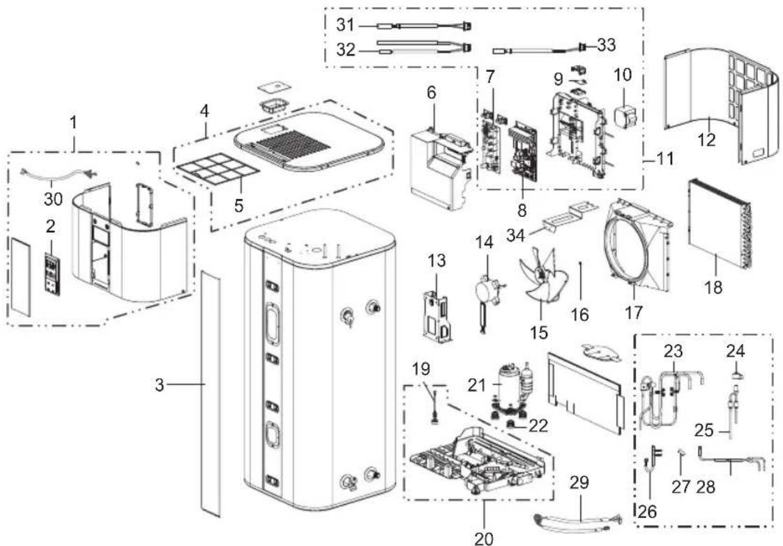
text_image
Exploded view diagram of a refrigerator with numbered parts for identification and assembly reference.
CAUTION
For your safety, Do not attempt to repair electronic controls, electrical wiring, heat pump, heating elements or other safety devices by yourself. Refer repair to authorized service center.
NOTE
- Check the water heater's rating plate on the unit for the acceptable voltage and wattage.
Replacement parts can be ordered through the distributor or store where the heater was purchased. All parts order should include following information:
- Model and serial number of the products.
- Voltage and wattage as marked on rating plate.
- Part description.
EN
Technical specification
| Description Unit WH20S F5 WH27S F5 | |||
| Tank Capacity L 200 270 | |||
| Dimension (Width x Height x Depth) mm 580 x 1625 x 582 580 x 2008 x 582 | |||
| Weight empty kg 100 119 | |||
| Diameter of water connections - G 3/4" | |||
| Diameter of condensate drainage connections - | 3/4" 1/2" | ||
| Type of corrosion protection | - | Impressed Current Cathodic protection | |
| Type of internal tank protection | - | Ceramic coated | |
| Max Working pressure | MPa | 1 | |
| Setting range of the water temperature | °C | 35 to 60 | |
| Operating temperature range of the heat pump | °C | -5 to 48 | |
| Refrigerant R134a | kg 0.65 | 0.75 | |
| Refrigerant volume in equivalent tonnes | T.eq.CO2 | 0.930 | 1.072 |
| Refrigerant design pressure (high side / low side) | MPa | 2.0 / 0.9 | |
| Power supply | |||
| Voltage | V | 230 | |
| Frequency | Hz | 50 | |
| Total Max power consumption | W 2600 | ||
| Max power consumption by heat pump | W | 550 | |
| Max power consumption by heating element | W 2050 | ||
| Protection rating | IPX1 | ||
| Air side | |||
| Air flow rate (H/M) | m3/min | 6.7/4.4 | 6.7/4.4 |
| Available static pressure | Pa | 90 | 90 |
EN


MANUEL D'UTILISATEUR
CHAUFFE-EAU DE POMPE À CHALEUR

Application LG ThinQ ....25
ENTRETIEN....27
natural_image
Two technical line drawings of vertical structural components with no visible text or symbolstext_image
Technical diagram showing a mechanical assembly with labeled components and directional arrows indicating motion or force.natural_image
Technical line drawing of a mechanical valve or fitting component (no text or symbols)natural_image
Line drawing of a mechanical valve or fitting with a threaded shaft and handle (no text or symbols)natural_image
Technical line drawing of a mechanical component with threaded end and flange (no text or symbols)text_image
Technical diagram showing mechanical assembly with labeled components and directional arrowsnatural_image
Illustration of a mechanical connector with a coiled cable and threaded shaft (no text or symbols)natural_image
Pure mechanical diagram of a pipe fitting with directional arrows, no text or symbols presentnatural_image
Simple line drawing of a mechanical component with an upward arrow indicating motion (no text or symbols)text_image
Diagram showing a mechanical component with labeled parts ① and ②, indicating directional movement or assembly.Application LG ThinQ
natural_image
Pure mechanical diagram showing a valve or pump assembly with an arrow indicating upward motion (no text or symbols)natural_image
Diagram of a hand pressing down on a device with a handle, showing internal structure and arrows indicating movement (no text or symbols)natural_image
Diagram of a hand pressing down on a device with a handle, showing no text or symbolstext_image
Diagram showing a pipe fitting with numbered components and directional arrows indicating flow or movement.natural_image
Technical line drawing of an internal appliance or housing with visible components and structural details (no text or symbols)text_image
Exploded view diagram of a refrigerator with numbered parts for identification and assembly reference.
ATTENTION
natural_image
Two identical line drawings of a vertical shelf or vent, showing top and side views with no text or symbols.ES
text_image
Technical diagram showing a structural component with labeled parts ① and ②, including directional arrows indicating movement or force.natural_image
Technical line drawing of a mechanical valve assembly (no text or symbols)natural_image
Technical line drawing of a mechanical component with threaded shaft and mounting bracket (no text or symbols)text_image
Technical diagram showing mechanical assembly with labeled components and directional arrowsnatural_image
Pure technical line drawing of a mechanical component with threaded end (no text or symbols)
natural_image
Illustration of a mechanical connector with a threaded shaft and black handle (no text or symbols)natural_image
Pure diagram of a pipe fitting with directional arrows indicating flow or movement (no text or symbols)natural_image
Simple line drawing of a mechanical component with an upward arrow indicating motion (no text or symbols)text_image
Diagram showing two labeled parts (① and ②) of a mechanical component with threaded end and directional arrows indicating movement.natural_image
Pure mechanical diagram showing a valve and nut assembly without any text, numbers, or symbolsnatural_image
Pure mechanical diagram showing a pump or valve assembly with an arrow indicating direction (no text or symbols)natural_image
Illustration of a hand pressing down on a small appliance with a handle (no text or symbols)natural_image
Diagram of a hand pressing down on a gridded table with a handle (no text or symbols)text_image
Diagram showing a pipe connection with numbered components and directional arrows indicating flow or movement.natural_image
Technical line drawing of an internal combustion engine assembly (no text or labels)text_image
Exploded view diagram of a refrigerator with numbered parts for identification and assembly reference.PRECAUCIÓN
natural_image
Two identical line drawings of a vertical shelf or vent, showing top and bottom panels with no text, numbers, or symbols.DE
text_image
Technical diagram showing a mechanical assembly with labeled components and directional arrows indicating motion or force.natural_image
Technical line drawing of a mechanical valve assembly (no text or symbols)natural_image
Line drawing of a mechanical component with threaded shaft and handle (no text or symbols)natural_image
Pure technical line drawing of a mechanical component with threaded end (no text or symbols)text_image
Technical diagram showing mechanical assembly with labeled components and directional arrowsnatural_image
Line drawing of a mechanical connector or fitting (no text or symbols)natural_image
Pure diagram of a pipe fitting with directional arrows indicating movement (no text or symbols)natural_image
Simple line drawing of a T-shaped pipe fitting with an upward arrow pointing to a cylindrical base (no text or symbols)natural_image
Pure mechanical diagram showing a pipe joint with a curved arrow indicating direction (no text or symbols)natural_image
Illustration of a hand pressing down on a device with a handle, showing no text or symbolsnatural_image
Line drawing of a hand pressing down on a curved surface with a grid-like structure (no text or symbols)text_image
Diagram showing a pipe fitting with numbered components and directional arrows indicating flow or movement.natural_image
Technical line drawing of an internal device with labeled components (no text or symbols present)text_image
Exploded view diagram of a refrigerator with numbered parts and labeled components
ACHTUNG
natural_image
Two technical line drawings of a mechanical component or panel assembly, showing vertical and horizontal sections with no text or symbols.Distanze minime

text_image
Dimensione minima della camera: 20 m³ 0.5 m 0.15 m 0.45 m 0.15 m 0.15 m 0.45 mNOTA
text_image
T T T Accessoritext_image
Technical diagram showing a mechanical assembly with labeled components and directional arrows indicating motion or force.natural_image
Technical line drawing of a mechanical valve component (no text or symbols)natural_image
Technical line drawing of a mechanical component with threaded shaft and handle (no text or symbols)natural_image
Pure technical line drawing of a mechanical component with threaded end (no text or symbols)text_image
Technical diagram showing mechanical assembly with labeled parts and directional arrows indicating motion or forcenatural_image
Pure diagram of a pipe fitting with directional arrows indicating flow or movement (no text or symbols)natural_image
Simple line drawing of a T-shaped pipe joint with an upward arrow pointing to a cylindrical component (no text or symbols)text_image
Diagram showing a mechanical component with labeled parts and directional arrows indicating motion or force.natural_image
Pure mechanical diagram showing a valve and nut assembly without any text or symbols- The installation of a residual current device (RCD) having a rated residual operating current not exceeding 30 mA is advisable.
- The rating of the residual current device (RCD) to be installed
text_image
188 °F °C Wi-Fi ©Heat Pump
Auto
Turbo
Schedule
Vacation
Anti Legionella
2
Wi-Fi (3s)

^ F/ ^ C (3s)

Reset Filter (3s)

Water Temp (3s)
1
natural_image
Pure mechanical diagram showing a shaft and housing assembly with an upward arrow, no text or symbols present.natural_image
Illustration of a hand pressing down on a curved surface with a grid-like structure (no text or symbols)natural_image
Diagram of a hand pressing down on a curved surface with heat sinks (no text or symbols)text_image
Diagram showing a pipe fitting with numbered components and directional arrows indicating flow or movement.natural_image
Technical line drawing of an internal combustion engine assembly (no text or labels)text_image
Exploded view diagram of a refrigerator with numbered parts and labeled componentsATTENZIONE
natural_image
Two technical line drawings of a mechanical or architectural component with vertical supports and a small inset detail (no text or symbols)Minimalne odstępy

text_image
Minimalna wielkość pomieszczenia: 20 m³ 0.5 m 0.15 m 0.45 m 0.15 m 0.15 m 0.45 mUWAGA
text_image
Technical diagram showing a mechanical assembly with labeled components ① and ②, including directional arrows indicating motion or force.natural_image
Technical line drawing of a mechanical valve assembly (no text or symbols)natural_image
Line drawing of a mechanical tool or connector with threaded shaft and handle (no text or symbols)natural_image
Technical line drawing of a mechanical component with threaded end and flange (no text or symbols)text_image
Technical diagram showing a mechanical assembly with labeled components and directional arrows indicating motion or force.natural_image
Technical line drawing of a mechanical connector or fitting (no text or symbols)natural_image
Pure mechanical diagram of a pipe fitting with directional arrows, no text or symbols presentnatural_image
Simple line drawing of a T-shaped pipe fitting with an upward arrow pointing to a cylindrical component (no text or symbols)text_image
Diagram showing two labeled parts (① and ②) of a mechanical component with threaded end and directional arrows indicating movement.natural_image
Technical line drawing of a mechanical component with a flanged end and arrow indicating rotation (no text or symbols)natural_image
Pure mechanical diagram showing a pipe joint with a curved arrow indicating direction (no text or symbols)natural_image
Illustration of a hand pressing down on a device with a grid-patterned lid (no text or symbols)natural_image
Line drawing of a hand pressing down on a chair with a tray and drawer (no text or symbols)text_image
Diagram showing a pipe fitting with numbered components and directional arrows indicating flow or movement.natural_image
Technical line drawing of an internal combustion engine unit with visible cooling fans and housing (no text or labels)text_image
Exploded view diagram of a refrigerator with numbered parts and labeled components
PRZESTROGA
Declaration of Conformity
EN

Hereby, LG Electronics declares that the radio equipment type Water Heater is in compliance with Directive 2014/53/EU. The full text of the EU declaration of conformity is available at the following internet address: http://www.lg.com/global/support/cedoc/cedoc#
UK DECLARATION OF CONFORMITY
EN

Hereby, LG Electronics declares that the radio equipment type Water Heater is in compliance with the relevant statutory requirements. The full text of the UK declaration of conformity is available at the following internet address: http://www.lg.com/global/support/cedoc/cedoc#
(EN) Contains fluorinated greenhouse gases.
(BG) Съдържа флуорсъдържащи парникови газове.
(ES) Contiene gases fluorados de efecto invernadero.
(CS) Obsahuje fluorované skleníkové plyny.
(DA) Indeholder fluorholdige drivhusgasser.
(DE) Enthält fluorierte Treibhausgase,
(ET) Sisaldab fluoritud kasvuhoonegaase.
(EL) Περιέχει φθοριούχα αέρια του θερμοκηπίου.
(FR) Contient des gaz à effet de serre fluorés.
(IT) Contiene gas fluorurati ad effetto serra.
(LV) Satur fluorētas siltumnīcefekta gāze.
(LT) Sudėtyje yra fluorintų šiltnamio efektą sukeliančių duju.
(HU) Fluortartalmú üvegházhatású gázokat tartalmaz.
(MT) Fih gassijiet fluworurati b'effett ta' serra-
(NL) Bevat gefluoreerde broeikasgassen.
(PL) Zawiera fluorowane gazy cieplamiane.
(PT) Contém gases fluorados com efeito de estufa-
(RO) Conține gaze fluorurate cu efect de seră-
(SK) Obsahuje fluórované skleníkové plyny.
(SL) Vsebuje fluorirane toplogredne pline.
(FI) Sisältää fluorattuja kasvihuonekaasuja.
(SV) Innehåller fluorerade växthusgaser
(NO) Inneholder fluorholdige klimagasser.
(IS) Inniheldur flúraðar gróðurhúsalofttegundir.
(HR) Sadržava fluorirane stakleniČke plinove
Hermetically sealed equipment

※ R134a GWP:1430
(GWP/PRG/GWP/PRP/GWP/GWP)
※ t-CO₂ eq = F-gas (kg) × GWP/1000
KORISNIČKI PRIRUČNIK
GRIJALICA VODE (BOJLER) S TOPLINSKOM PUMPOM

Prije upotrebe uređaja pažljivo pročitajte ovaj korisnički priručnik i čuvajte ga pri ruci za buduću uporabu.
Originalne upute
HR HRVATSKI SL SLOVENŠČINA HU MAGYAR BG БЪЛГАРСКИ
SR SRPSKI CNR MONTÉNÉGRIN BS BOSANSKI SQ SHQIP
MK MAKEDOHСКИ NL NEDERLANDSEL EΛΛΗΝΙΚΑ RO ROMÂNΑ
SK SLOVENČINACZ ČEŠTINA PT PORTUGUÊS
CE UK CA
text_image
Barcode image with black and white vertical bars, no visible text or symbols beyond the patternMFL71409210
Rev.00_090923
LG Electronics Inc. Single Point of Contact (EU/UK) : LG Electronics European Shared Service Center B.V. Krijgsman 1, 1186 DM Amstelveen, The Netherlands
www.lg.com
Autorsko pravo © 2023 LG Electronics Inc. Sva prava pridržana.
SIGURNOSNE UPUTE....3
Mjere opreza ....4
UGRADNJA....12
VAŽNE SIGURNOSNE UPUTE

UPOZORENJE
natural_image
Two identical line drawings of a cabinet or shelf with vertical supports and a small inset showing a small object (no text or symbols)Minimalni razmak
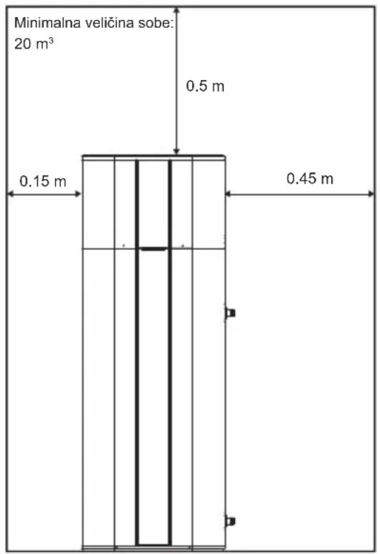
text_image
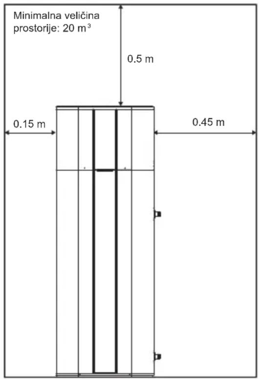
Minimalna veličina sobe: 20 m³ 0.5 m 0.15 m 0.45 m
text_image
0.15 m 0.15 m 0.45 mNAPOMENA
text_image
Technical diagram showing a mechanical assembly with labeled parts ① and ②, likely illustrating a structural or mechanical assembly.natural_image
Technical line drawing of a mechanical valve assembly (no text or symbols)2 Ugradite odvodni ventil u otvor sa oznakom „odvodni ventil“.
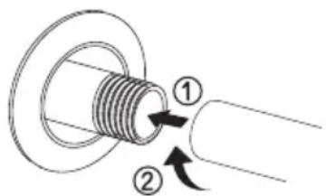
Ugradnja T&P sigurnosnog ventila
natural_image
Technical line drawing of a mechanical component with threaded shaft and flange (no text or symbols)2 Ugradite T&P sigurnosni ventil u otvor sa oznakom T&P sigurnosni ventil
natural_image
Pure mechanical component diagram showing a threaded shaft and curved handle (no text or symbols)text_image
Technical diagram showing mechanical assembly with labeled components and directional arrows indicating motion or forcenatural_image
Illustration of a mechanical joint or connector with a curved arm and threaded shaft (no text or symbols)natural_image
Pure diagram of a pipe fitting with directional arrows indicating flow or movement (no text or symbols)3 Pomoću odobrenog brtvila umetnite PVC cijev u ženski kraj. Odvod kondenzata mora se cijevima dovesti do odgovarajućeg odvoda.

natural_image
Simple line drawing of a mechanical component with an upward arrow pointing to a cylindrical base (no text or symbols)natural_image
Technical line drawing of a mechanical component with threaded shaft and mounting base (no text or symbols)3 Spojite hladnu i toplu vode pomoću 3/4" G.
text_image
Diagram showing a mechanical component with labeled parts and directional arrows indicating motion or force.4 Ugradite zaporni ventil u vod hladne vode u blizini bojlera.
5 Instalirajte izolaciju na cijevi za hladnu i toplu vodu. Izolacija cijevi za toplu vodu može povećati energetsku učinkovitost.
Da napunite vodogrijalicu (bojler)
⚠ UPOZORENJE
natural_image
Pure mechanical diagram showing a valve and nut assembly without any text, numbers, or symbols2 Uključite dovod hladne vode
3 Polako otvorite svaku slavinu za toplu vodu i pustite da voda teče dok ne poteče punim mlazom.
4 Pustite da voda teče punim mlazom nekoliko minuta.
Uspostavljanje električnih veza

UPOZORENJE
text_image
Diagram showing hand finger pressing a circle with directional arrows, next to a circular arrow indicating rotation.text_image
Diagram showing a hand pointing at a Wi-Fi icon to indicate wireless signal transformationNAPOMENA
- Da biste potvrdili da postoji Wi-Fi veza provjerite svijetli li ikona na upravljačkoj ploči.
- Uređaj podržava samo 2,4 GHz Wi-Fi mreže. Da biste provjerili mrežnu frekvenciju, obratite se svojem davatelju Internet usluga ili pogledajte upute ežičnog usmjerivača.
- LG ThinQ nije odgovoran za bilo kakve probleme mrežne veze ili bilo kakve pogreške, kvarove ili greške uzrokovane mrežnom vezom.
- Ako uređaj ima problema pri povezivanju s Wi-Fi mrežom, možda je predaleko od usmjernika (router). Nabavite Wi-Fi repetitor (proširivač raspona) kako biste poboljšali jačinu Wi-Fi signala.
- Wi-Fi mreža se možda neće povezati ili će biti prekinuta zbog okruženja u kojem se nalazi.
- Mrežna veza možda neće ispravno raditi, ovisno o davatelju internetskih usluga.
-
Okolno bežično okruženje može uzrokovati spori rad bežične mreže.
-
Uređaj nije moguće registrirati zbog problema sa bežičnim prijenosom signala. Isključite uređaj i sačekajte jednu minutu prije ponovnog pokušaja.
- Ako je na bežičnom usmjerivaču omogućen vatrozid, onemogućite vatrozid ili mu dodajte iznimku.
- Naziv bežične mreže (SSID) trebao bi biti kombinacija engleskih slova i brojeva. (Ne koristite posebne znakove.)
- Korisničko sučelje pametnog telefona (UI) može se razlikovati ovisno o mobilnom operativnom sustavu (OS) i proizvođaču.
- Ako je sigurnosni protokol usmjerivača postavljen na ^WEP , možda nećete uspjeti postaviti mrežu. Odaberite druge sigurnosne protokole (preporučujemo WPA2) i ponovo registrirajte proizvod.
Instaliranje LG ThinQ aplikacije
Potražite LG ThinQ aplikaciju u trgovini Google Play ili Apple App Store na pametnom telefonu.
natural_image
Two identical line drawings of a cabinet or enclosure structure with vertical supports and a small circular component, no text or symbols present.text_image
Technical diagram showing a structural component with labeled parts ① and ②, likely illustrating a mechanical or architectural assembly.4 Grelnik vode rahlo nagnite in previdno odvijte grelnik vode s palete.
Temperaturna ekspanzija
Ugotovite, će je na dovodu vode protipovratni ventil. Preverite pri komunalnem podjetju. Protipovratni ventil na dovodu hladne vode ustvari "zaprt sistem vode".
natural_image
Technical line drawing of a mechanical valve assembly (no text or symbols)natural_image
Technical line drawing of a mechanical component with threaded shaft and circular head (no text or symbols)natural_image
Pure mechanical component diagram showing a cylindrical shaft with threaded end and circular head (no text or symbols)text_image
Technical diagram showing mechanical assembly with labeled components and directional arrowsnatural_image
Technical line drawing of a mechanical joint or connector (no text or symbols)2 Na primarni odtočni priključek pritrdite koleno s 3/4" na 3/4".

natural_image
Pure diagram of a pipe fitting with directional arrows indicating flow or movement (no text or symbols)3 S primerno tesnilno maso vstavite PVC cev v ženski konec. Odtok kondenzata mora biti speljan do ustreznega odtoka.

natural_image
Simple line drawing of a mechanical component with an arrow pointing to a cylindrical base (no text or symbols)4 S pomočjo 1/2" PVC cevi, kolena z 1/2" na 1/2 " in primerne tesnilne mase pritrdite koleno na sekundarni odtočni priključek in vstavite PVC cev v ženski konec.
natural_image
Technical line drawing of a mechanical component with threaded shaft and circular base (no text or symbols)3 Priključite dovod hladne in vroče vodo s 3/4" cevmi.
text_image
Diagram showing two labeled parts (① and ②) of a mechanical component with threaded end and directional arrows indicating motion.natural_image
Pure mechanical diagram showing a valve and housing assembly without any text, numbers, or symbolstext_image
Diagram showing hand gesture pointing to a circle with directional arrows, next to a circular arrow symboltext_image
Diagram showing a hand interacting with wireless signals to form a Wi-Fi symbol, indicating signal transmission or interaction.OPOMBA
natural_image
Pure technical line drawing of two identical mechanical or electrical components with no text, numbers, or symbolstext_image
Technical diagram showing a mechanical assembly with labeled components ① and ②, likely illustrating a structural or mechanical assembly.natural_image
Technical line drawing of a mechanical valve assembly (no text or symbols)natural_image
Technical line drawing of a mechanical component with threaded shaft and flange (no text or symbols)natural_image
Technical line drawing of a mechanical component with threaded end and flange (no text or symbols)text_image
Technical diagram showing mechanical assembly with labeled parts and directional arrows indicating motion or forcenatural_image
Technical line drawing of a mechanical connector or fitting (no text or symbols)natural_image
Pure mechanical diagram of a pipe fitting with directional arrows, no text or symbols presentnatural_image
Simple line drawing of a mechanical component with an upward arrow pointing to a cylindrical base (no text or symbols)natural_image
Technical line drawing of a mechanical component with threaded shaft and circular base (no text or symbols)text_image
Diagram showing a mechanical component with labeled parts and directional arrows indicating motion or force.natural_image
Pure mechanical diagram showing a valve and housing assembly without any text, numbers, or symbolstext_image
Diagram showing hand gesture pointing to a circle with bidirectional arrows, followed by rightward arrow symboltext_image
Diagram showing a hand interacting with wireless signals to form a Wi-Fi symbolMEGJEGYZÉS
natural_image
Pure technical line drawing of two vertical panels with no text, numbers, or symbolsМинимално отстояние
text_image
Technical diagram showing a structural component with labeled parts ① and ②, likely illustrating a mechanical or architectural assembly.natural_image
Technical line drawing of a mechanical valve assembly (no text or symbols)natural_image
Technical line drawing of a mechanical component with threaded shaft and handle (no text or symbols)natural_image
Pure mechanical component diagram showing a threaded pipe with a flanged end (no text or symbols)text_image
Technical diagram showing mechanical assembly with labeled components and directional arrows indicating motion or forcenatural_image
Illustration of a mechanical pipe fitting with threaded end (no text or symbols)natural_image
Pure mechanical diagram of a pipe fitting with directional arrows, no text or symbols presentnatural_image
Simple line drawing of a mechanical component with an arrow indicating upward motion (no text or symbols)natural_image
Technical line drawing of a mechanical component with threaded shaft and circular base (no text or symbols)text_image
Diagram showing a mechanical component with labeled parts and directional arrows indicating motion or force.natural_image
Pure mechanical diagram showing a valve and nut assembly without any text, numbers, or symbolstext_image
Diagram showing hand gesture pointing to a circle with bidirectional arrows, followed by rightward arrow symboltext_image
Diagram showing a hand interacting with wireless signals to form a Wi-Fi symbolЗАБЕЛЕЖКА
BEZBEDNOSNA UPUTSTVA ....3
VAŽNA BEZBEDNOSNA UPUTSTVA
⚠ UPOZORENJE
natural_image
Pure technical line drawings of two identical mechanical components with no text or symbolsMinimalna odstojanja
text_image
Minimalna veličina prostorije: 20 m³ 0.5 m 0.15 m 0.45 m
text_image
0.15 m 0.15 m 0.45 mNAPOMENA
- Radi budućeg održavanja, preporučuje se razmak od najmanje 1 m između bilo kog predmeta i leve, desne i zadnje strane uređaja.
text_image
Technical diagram showing a mechanical assembly with labeled components ① and ②, likely illustrating a turning or positioning process.natural_image
Technical line drawing of a mechanical valve component (no text or symbols)2 Ugraditi odvodni ventil u otvor označen sa „Drain Valve“.
Ugradnja sigurnosnog ventila
Uzeti sigurnosni ventil iz pakovanja.
1 Omotati narezani kraj teflonskom trakom da bi se sprečilo curenje.
natural_image
Technical line drawing of a mechanical component with threaded end and handle (no text or symbols)2 Ugraditi sigurnosni ventil u otvor označen sa „sigurnosni ventil“. (T&P relief valve)
Povezivanje ispusne cevi sigurnosnog ventila
⚠ UPOZORENJE
natural_image
Pure mechanical component diagram showing a threaded pipe joint with a curved handle (no text or symbols)2 Postaviti ispusnu cev na izlazni kraj sigurnosnog ventila. Ispusna cev mora imati pad od ventila pa nadalje da bi omogućila odvod vode kako iz sigurnosnog ventila, tako i iz odvodne cevi.
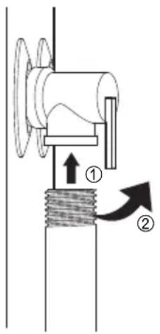
text_image
Technical diagram showing mechanical assembly with labeled components and directional arrows3 Kraj ispusne cevi mora biti sproveden do odgovarajućeg odvoda.

* Iz ispusne cevi regulacionog ventila može kapati voda i kraj te cevi mora ostati slobodan.
* Ispusni ventil treba redovno čisititi od kamenca i proveravati da nije zapušen.
* Ispusna cev mora imati pad od ventila nadalje i mora se nalaziti u okruženju zaštićenom od smrzavanja.
Ugradnja cevi odvoda kondenzata
NAPOMENA
- Prilikom povezivanja fitinga na odvodnim cevima, NE SME SE preterano zatezati.
Preterano zatezanje fitinga može oštetiti posudu za skupljanje vode.
- Kondenzat iz uređaja nije kisele prirode.
Cevi za odvod kondenzata i priključci za odvode moraju odgovarati državnim i lokalnim propisima.
Ne smanjivati presek odvodne cevi na veličinu manju od priložene uz uređaj.
Postarati se da cev za odvod kondenzata ima odgovarajući pad radi pravilnog odvodnjavanja.
natural_image
Technical line drawing of a mechanical pipe fitting with a coiled cable (no text or symbols)natural_image
Pure diagram of a pipe fitting with directional arrows indicating flow or movement (no text or symbols)3 Umetnuti PVC cev namazanu odobrenim zaptivačem u ženski kraj. Odvod kondenzata se mora sprovesti do odgovarajućeg izliva.
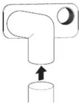
natural_image
Simple line drawing of a mechanical component with an upward arrow pointing to a cylindrical base (no text or symbols)4 Na PVC cev od 1/2" postaviti koleno 1/2" na 1/2" sa jednim navojem, pa odobrenim zaptivačem pričvrstiti koleno na sekundarni priključak odvoda i umetnuti PVC cev u ženski kraj.
Povezivanje na vodovodnu mrežu
NAPOMENA
- NE TREBA direktno lemiti ili variti na priključke za toplu ili hladnu vodu. Ako se rade meki lemovi, cev zalemiti za adapter pre povezivanja adaptera na cevi za toplu ili hladnu vodu na grejaču. Ukoliko se na priključke za dovod vode primeni visoka tempteratura, doći će do trajnog oštećenja unutrašnje plastične obloge u njima.
* Maksimalni pritisak u dovodnoj cevi za hladnu vodu je 0.8 MPa. Ako je dovodni pritisak vode veći od 0.8 MPa, ugraditi ventil za smanjenje pritiska.
* Povezati vodu za punjenje ili dopunu sistema grejanja kako je navedeno u EN1717 / EN61770 kako biste izbegli zagađenje vode za piće povratnim tokom.
| Maksimalne i minimalne radne temperature vode (°C) | 35 / 62 |
| Maksimalni i minimalni radni pritisci (MPa) | - / 0.8 |
Pogledati „Uputstva za ugradnju“ za preporučene tipične instalacije.
natural_image
Technical line drawing of a mechanical component with threaded shaft and circular base (no text or symbols)3 Povezati dovod hladne i odvod vruće vode narezanim cevima od 3/4".
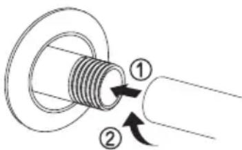
text_image
Diagram showing a mechanical component with labeled parts and directional arrows indicating motion or force.4 Ugraditi zaporni ventil u vod hladne vode u blizini grejača.
5 Postaviti izolaciju na cevi za hladnu i toplu vodu. Izolovanje cevi za toplu vodu može povećati energetsku efikasnost.
Punjenje grejača vodom

UPOZORENJE
Ne treba uključivati električno napajanje grejača ukoliko kotao nije potpuno pun vode. Garancija za grejač vode ne pokriva oštećenja ili kvarove nastale usled rada sa praznim ili delimično praznim kotlom.
1 Proveriti da li je odvodni ventil grejača potpuno zatvoren.

natural_image
Technical line drawing of a mechanical component with a rotating arrow (no text or symbols)2 Pustiti hladnu vodu
3 Lagano otvoriti sve slavine za toplu vodu i pustiti da voda počne da teče punim mlazom.
4 Pustiti da voda teče punim mlazom nekoliko minuta.
Povezivanje na električnu mrežu

UPOZORENJE
text_image
Diagram showing hand gesture pointing to a circle with bidirectional arrows, next to a circular arrow symbol.text_image
Diagram showing a hand interacting with wireless signals to form a Wi-Fi symbolNAPOMENA
- Da biste potvrdili Wi-Fi vezu, proverite da li ikona na komandnoj tabli svetli.
- Uređaj podržava samo Wi-Fi mreže od 2.4 GHz. Za proveru frekvencije mreže, obratiti se pružaocu usluge interneta ili proveriti uputstvo rutera.
- LG ThinQ ne snosi odgovornost za probleme sa povezivanjem na mrežu niti za bilo koje smetnje, kvarove ili greške izazvane povezivanjem na mrežu.
- Ako uređaj ne može da se poveže na Wi-Fi mrežu, moguće je da je predaleko od rutera. Kupite pojačivač Wi-Fi signala da biste povećali njegovu snagu.
- Veza sa Wi-Fi mrežom možda neće biti uspostavljena ili će biti prekinuta zbog uslova u kojima funkcioniše kućna mreža.
- Mrežna veza možda neće raditi kako treba u zavisnosti od pružaoca internet usluga.
-
Vaša bežična mreža može biti spora zbog okolnog bežičnog okruženja.
-
Uređaj se ne može registrovati zbog problema sa bežičnim prenosom signala. Isključite uređaj i sačekajte oko minut pre ponovnog pokušaja.
- Ako je fajervol na bežičnom ruteru uključen, isključite ga ili dodajte izuzetak.
- Ime bežične mreže (SSID) trebalo bi da bude kombinacija engleskih slova i brojeva. (Ne koristiti specijalne znakove.)
- Korisnički interfejs telefona (UI) može se razlikovati u zavisnosti od mobilnog operativnog sistema (OS) i proizvođača.
- Ako je sigurnosni protokol rutera podešen na WEP, možda nećete moći da postavite mrežu. Molimo vas da je promenite na druge bezbednosne protokole (WPA2se preporučuje) i da ponovo prijavite uređaj.
Instalacija aplikacije LG ThinQ
Potražite aplikaciju LG ThinQ na svom telefonu u Google Play Store ili u Apple App Store. Pratite uputstva za preuzimanje i instaliranje aplikacije.
Smart Diagnosis™
Koristiti ovu funkciju kao pomoć u utvrđivanju i rešavanju problema sa uređajem.
NAPOMENA
BEZBEDNOSNA UPUTSTVA ....3
Mjere predostrožnosti....4
UGRADNJA....12
VAŽNA BEZBEDNOSNA UPUTSTVA

UPOZORENJE
Kako biste umanjili rizik od nastajanja požara, strujnog udara ili povrijede lica prilikom korišćenja proizvoda, potrebno je poštovati osnovne mjere predostrožnosti o bezbjednosti, uključujući i one koje slede:
Djecu u domaćinstvu:
Nije predviđeno da ovaj uređaj koriste osobe (uključujući djecu) sa smanjenim fizičkim, senzornim ili mentalnim sposobnostima ili s nedostatkom iskustva i znanja, osim ako su pod nadzorom osobe odgovorne za njihovu bezbjednost ili im je ta osoba dala uputstva o korišćenju ovog uređaja. Djeca moraju biti pod nadzorom kako bi se osiguralo da se ne igraju uređajem.
natural_image
Pure technical line drawing of two identical mechanical components with no text or symbolsMinimalna odstojanja

text_image
Minimalna veličina prostorije: 20 m³ 0,5 m 0,15 m 0,45 m
text_image
0,15 m 0,15 m 0,45 mNAPOMJENA
- Radi budućeg održavanja, preporučuje se razmak od najmanje 1 m između bilo kog predmeta i leve, desne i zadnje strane uređaja.
text_image
Technical diagram showing a mechanical assembly with labeled components ① and ②, likely illustrating a structural or mechanical assembly.natural_image
Technical line drawing of a mechanical valve assembly (no text or symbols)2 Ugraditi odvodni ventil u otvor označen sa „Drain Valve“.
Ugradnja sigurnosnog ventila
Uzeti sigurnosni ventil iz pakovanja.
1 Omotati narezani kraj teflonskom trakom da bi se spriječilo curenje.
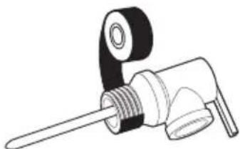
natural_image
Technical line drawing of a mechanical component with a handle and threaded shaft (no text or symbols)2 Ugraditi sigurnosni ventil u otvor označen sa „sigurnosni ventil“. (T&P relief valve)
natural_image
Pure technical line drawing of a mechanical component with threaded end (no text or symbols)text_image
Technical diagram showing mechanical assembly with labeled components and directional arrows3 Kraj ispusne cijevi mora biti sproveden do odgovarajućeg odvoda.

* Iz ispusne cijevi regulacionog ventila može kapati voda i kraj te cijevi mora ostati slobodan.
* Ispusni ventil treba redovno čisititi od kamenca i provjeravati da nije zapušen.
* Ispusna cijev mora imati pad od ventila nadalje i mora se nalaziti u okruženju zaštićenom od smrzavanja.
natural_image
Simple line drawing of a mechanical component with an upward arrow pointing to a cylindrical base (no text or symbols)natural_image
Technical line drawing of a mechanical component with threaded end and curved arm (no text or symbols)natural_image
Pure diagram of a pipe fitting with a circular arrow indicating left motion (no text or symbols)natural_image
Technical line drawing of a mechanical component with threaded shaft and circular base (no text or symbols)text_image
Diagram showing a mechanical component with labeled parts and directional arrows indicating motion or force.natural_image
Mechanical diagram showing a rotating component with a flanged end (no text or symbols)2 Pustiti hladnu vodu
3 Lagano otvoriti sve slavine za toplu vodu i pustiti da voda počne da teče punim mlazom.
4 Pustiti da voda teče punim mlazom nekoliko minuta.
text_image
Diagram showing hand gesture pointing to a circle with directional arrows, next to a circular arrow symbol.text_image
Diagram showing a hand interacting with wireless signals to form a Wi-Fi symbolNAPOMJENA
- Da biste potvrdili Wi-Fi vezu, provjerite da li ikona na komandnoj tabli svetli.
- Uređaj podržava samo Wi-Fi mreže od 2,4 GHz. Za proveru frekvencije mreže, obratiti se pružaocu usluge interneta ili provjeriti uputstvo rutera.
- LG ThinQ ne snosi odgovornost za probleme sa povjezivanjem na mrežu niti za bilo koje smetnje, kvarove ili greške izazvane povjezivanjem na mrežu.
- Ako uređaj ne može da se povježe na Wi-Fi mrežu, moguće je da je predaleko od rutera. Kupite pojačivač Wi-Fi signala da biste povećali njegovu snagu.
- Veza sa Wi-Fi mrežom možda neće biti uspostavljena ili će biti prekinuta zbog uslova u kojima funkcioniše kućna mreža.
- Mrežna veza možda neće raditi kako treba u zavisnosti od pružaoca internet usluga.
-
Vaša bežična mreža može biti spora zbog okolnog bežičnog okruženja.
-
Uređaj se ne može registrovati zbog problema sa bežičnim prenosom signala. Isključite uređaj i sačekajte oko minut prije ponovnog pokušaja.
- Ako je fajervol na bežičnom ruteru uključen, isključite ga ili dodajte izuzetak.
- Ime bežične mreže (SSID) trebalo bi da bude kombinacija engleskih slova i brojeva. (Ne koristiti specijalne znakove.)
- Korisnički interfejs telefona (UI) može se razlikovati u zavisnosti od mobilnog operativnog sistema (OS) i proizvođača.
- Ako je bezbjednosni protokol rutera podešen na WEP, možda nećete moći da postavite mrežu. Molimo vas da je promjenite na druge bezbjednosne protokole (WPA2se preporučuje) i da ponovo prijavite uređaj.
Instalacija aplikacije LG ThinQ
Potražite aplikaciju LG ThinQ na svom telefonu u Google Play Store ili u Apple App Store. Pratite uputstva za preuzimanje i instaliranje aplikacije.
Smart Diagnosis™
Koristiti ovu funkciju kao pomoć u utvrđivanju i rešavanju problema sa uređajem.
NAPOMJENA
SIGURNOSNA UPUTSTVA....3
Mjere opreza ....4
INSTALACIJA....12
SMART FUNKCIJE ......25
LG ThinQ aplikacija ....25
natural_image
Pure technical line drawings of two identical mechanical or electrical components with no text, numbers, or symbols.Minimalni razmak

text_image
Minimalna veličina prostora: 20 m³ 0.5 m 0.15 m 0.45 m
text_image
0.15 m 0.15 m 0.45 mNAPOMENA
text_image
Technical diagram showing a mechanical assembly with labeled components ① and ②, likely illustrating a structural or mechanical assembly.4 Lagano nagnite bojler i pažljivo skinite bojler sa palete.
Toplinska ekspanzija
Utvrdite da li je nepovratni ventil prisutan na dovodnom vodu. Provjerite kod lokalnog vodovoda. Nepovratni ventil smješten u dovodnom vodu hladne vode stvoriće „zatvoreni sistem vode“
natural_image
Technical line drawing of a mechanical valve component (no text or symbols)2 Ugradite odvodni ventil u otvor sa oznakom „odvodni ventil“.
Ugradnja T&P sigurnosnog ventila
natural_image
Technical line drawing of a mechanical component with threaded end and handle (no text or symbols)2 Ugradite T&P sigurnosni ventil u otvor sa oznakom T&P sigurnosni ventil
natural_image
Pure technical line drawing of a mechanical component with threaded end (no text or symbols)text_image
Technical diagram showing mechanical assembly with labeled components and directional arrowsnatural_image
Technical line drawing of a mechanical component with threaded end and curved arm (no text or symbols)natural_image
Pure diagram of a pipe fitting with a circular arrow indicating direction (no text or symbols)3 Pomoću odobrenog zaptivača umetnite PVC cijev u ženski kraj. Odvod kondenzata mora se odvesti do odgovarajućeg odvoda.

natural_image
Simple line drawing of a mechanical component with an upward arrow pointing to a cylindrical base (no text or symbols)4 Koristeći 1/2" PVC cjevovode, koljeno sa 1/2" kliznim poklopcem i 1/2" G, i odobreni zaptivač pričvrstite koljeno na sekundarni priključak za odvod i umetnite PVC cijev u ženski kraj.
natural_image
Technical line drawing of a mechanical component with threaded shaft and circular base (no text or symbols)text_image
Diagram showing a mechanical component with labeled parts and directional arrows indicating motion or force.4 Ugradite zaporni ventil u vod hladne vode u blizini bojlera.
5 Instalirajte izolaciju na cijevi za hladnu i toplu vodu. Izolacija cijevi za toplu vodu može povećati energetsku efikasnost.
Da biste napunili bojler
⚠ UPOZORENJE
Nemojte uključivati električno napajanje bojlera ako rezervoar nije potpuno pun vode. Garancija za bojler ne pokriva oštećenja ili kvarove nastale usljed rada sa praznim ili djelimično praznim rezervoarom.
1 Uvjerite se da je odvodni ventil bojlera potpuno zatvoren.

natural_image
Technical line drawing of a mechanical component with a rotating arrow (no text or symbols)2 Uključite dovod hladne vode
3 Polako otvorite svaku slavinu za toplu vodu i pustite da voda teče dok ne krene punim mlazom.
4 Pustite da voda teče punim mlazom nekoliko minuta.
Pravljenje električnih veza

UPOZORENJE
text_image
Diagram showing hand gesture pointing to a circle with directional arrows, next to a circular arrow symbol3 Povežite pametni telefon sa bežičnim ruterom.
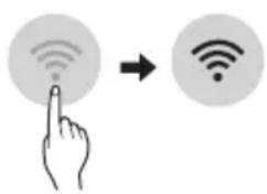
text_image
Diagram showing a hand interacting with wireless signals to form a Wi-Fi symbolNAPOMENA
- Da biste potvrdili Wi-Fi vezu provjerite da li svijetli znak na kontrolnoj tabli.
- Uređaj podržava samo 2.4 GHz Wi-Fi mreže. Da biste proverili mrežnu frekvenciju, obratite se dobavljaču Internet usluga ili pogledajte uputstvo za bežični ruter.
- LG ThinQ nije odgovoran za bilo kakve probleme s mrežnom vezom ili bilo kakve greške, kvarove ili probleme uzrokovane mrežnom vezom.
- Ako uređaj ima problema sa povezivanjem na Wi-Fi mreži, možda se nalazi predaleko od rutera. Kupite Wi-Fi repetitor (pojačivač signala) da biste poboljšali jačinu Wi-Fi signala.
- Wi-Fi mreža se možda neće povezati ili će biti prekinuta zbog okruženja u kojem se nalazi.
- Mrežna veza možda neće raditi pravilno u zavisnosti od dobavljača internetskih usluga.
-
Okruženje u kojem se nalazi mreža može da učini da usluga sporo radi
-
Uređaj nije moguće registrovati zbog problema sa bežičnim prenosom signala. Isključite uređaj i sačekajte jednu minutu prije nego opet pokušate.
- Ako je na bežičnom ruteru omogućen zaštitni zid, onemogućite zaštitni zid ili dodajte izuzetak.
- Ime bežične mreže (SSID) trebalo bi da bude kombinacija engleskih slova i brojeva. (Nemojte koristiti specijalne karaktere.)
- Korisnički interfejs pametnog telefona (UI) može se razlikovati u zavisnosti od mobilnog operativnog sistema (OS) i proizvođača.
- Ako je protokol sigurnosti rutera postavljen na WEP, možda nećete uspjeti da podesite mrežu. Promijenite ga na druge sigurnosne protokole (preporučuje se WPA2) i registrujte proizvod ponovo.
Instaliranje LG ThinQ aplikacije
Potražite LG ThinQ aplikaciju u prodavnicama Google Play ili Apple App na pametnom telefonu. Pratite uputstva za preuzimanje i instaliranje aplikacije.
Pametna dijagnoza™
Koristite ovu funkciju da biste pronašli i riješili probleme sa vašim uređajem.
NAPOMENA
natural_image
Pure technical line drawing of two identical mechanical components with no text or symbolsHapësirat minimale

text_image
Madhësia minimale e dhomës: 20 m³ 0.5 m 0.15 m 0.45 m
text_image
0.15 m 0.15 m 0.45 mSHËNIM
text_image
Technical diagram showing a mechanical assembly with labeled components ① and ②, likely illustrating a structural or mechanical assembly.4 Zhvendosni pak nga vendi bojlerin dhe me kujdes rrokullisni bojlerin nga paleta.
Zgjerimi termik
natural_image
Technical line drawing of a mechanical valve assembly (no text or symbols)natural_image
Technical line drawing of a mechanical component with threaded shaft and handle (no text or symbols)natural_image
Pure technical line drawing of a mechanical component with no text or symbolstext_image
Technical diagram showing mechanical assembly with labeled components and directional arrows indicating motion or forcenatural_image
Technical line drawing of a mechanical joint or connector (no text or symbols)natural_image
Pure diagram of a pipe fitting with directional arrows indicating flow or movement (no text or symbols)natural_image
Simple line drawing of a mechanical component with an arrow pointing to a cylindrical base (no text or symbols)natural_image
Technical line drawing of a mechanical component with threaded shaft and circular base (no text or symbols)text_image
Diagram showing a mechanical component with numbered parts and directional arrows indicating motion or forcenatural_image
Pure mechanical diagram showing a valve and housing assembly without any text, numbers, or symbolstext_image
Diagram showing hand finger pressing a circle with directional arrows, indicating press or navigation action3 Lidhni smartfonin me rrugëzuesin me valë.
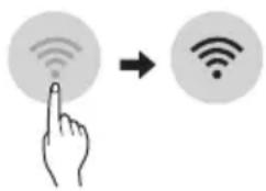
text_image
Diagram showing a hand pointing at a Wi-Fi icon with signal waves, followed by a Wi-Fi symbol to indicate wireless access.SHËNIM
natural_image
Pure technical line drawings of a mechanical or architectural component without any text, numbers, or symbolsМинимален простор

text_image
Минимална големина на собата: 20 м³ 0.5 м 0.15 м 0.45 м
text_image
0.15 M 0.15 M 0.45 MЗАБЕЛЕШКА
text_image
Technical diagram showing a mechanical assembly with labeled components ① and ②, likely illustrating a turning or positioning process.natural_image
Technical line drawing of a mechanical valve assembly (no text or symbols)natural_image
Technical line drawing of a mechanical component with threaded shaft and flange (no text or symbols)natural_image
Technical line drawing of a mechanical component with threaded end and circular head (no text or symbols)text_image
Technical diagram showing mechanical assembly with labeled components and directional arrows indicating motion or forcenatural_image
Technical line drawing of a mechanical joint or connector (no text or symbols)natural_image
Pure diagram of a pipe fitting with directional arrows indicating flow or movement (no text or symbols)natural_image
Simple line drawing of a mechanical component with an upward arrow pointing to a cylindrical base (no text or symbols)natural_image
Technical line drawing of a mechanical component with threaded shaft and circular base (no text or symbols)text_image
Diagram showing a mechanical component with labeled parts and directional arrows indicating motion or force.natural_image
Technical line drawing of a mechanical component with a rotating arrow (no text or symbols)text_image
Diagram showing hand gesture pointing to two directional arrows, one with up/down arrow and one with up/down arrowtext_image
Diagram showing a hand interacting with wireless signals to form a Wi-Fi symbolЗАБЕЛЕШКА
natural_image
Pure technical line drawing of two identical mechanical or electrical components with no text, numbers, or symbolsMinimale ruimte
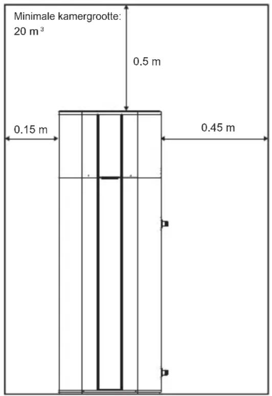
text_image
Minimale kamergrootte: 20 m³ 0.5 m 0.15 m 0.45 m
text_image
0.15 m 0.15 m 0.45 mOPMERKING
text_image
Technical diagram showing a structural component with labeled parts ① and ②, indicating directional movement or force.natural_image
Technical line drawing of a T-junction valve with threaded port and handle (no text or symbols)natural_image
Technical line drawing of a mechanical component with threaded shaft and handle (no text or symbols)2 Installeer de T&P onlastingsklep in de opening die gemarkeerd is met T&P onlastingsklep.
natural_image
Pure technical line drawing of a mechanical component with threaded end (no text or symbols)text_image
Technical diagram showing mechanical assembly with labeled components and directional arrowsnatural_image
Technical line drawing of a mechanical joint or connector (no text or symbols)natural_image
Pure diagram of a pipe fitting with directional arrows indicating flow or movement (no text or symbols)natural_image
Simple line drawing of a mechanical component with an upward arrow pointing to a cylindrical base (no text or symbols)natural_image
Technical line drawing of a mechanical component with threaded shaft and circular base (no text or symbols)text_image
Diagram showing two labeled parts (① and ②) of a mechanical component with threaded end and curved arrow indicating rotation or movement.natural_image
Mechanical diagram showing a rotating component with a flanged end (no text or symbols)text_image
Diagram showing hand gesture pointing to a circle with directional arrows, next to a circular arrow symboltext_image
Diagram showing a hand pointing at a Wi-Fi icon with signal waves, followed by a Wi-Fi symbol.OPMERKING
natural_image
Pure technical line drawings of two mechanical components with no text or symbolstext_image
Technical diagram showing a mechanical assembly with labeled components ① and ②, likely illustrating a structural or mechanical assembly.natural_image
Technical line drawing of a mechanical valve assembly (no text or symbols)natural_image
Technical line drawing of a mechanical component with a threaded shaft and handle (no text or symbols)natural_image
Technical line drawing of a mechanical component with threaded end and circular head (no text or symbols)text_image
Technical diagram showing mechanical assembly with labeled parts and directional arrows indicating movement or forcenatural_image
Technical line drawing of a mechanical pipe fitting with a coiled cable (no text or symbols)natural_image
Pure diagram of a pipe fitting with a circular arrow indicating direction (no text or symbols)natural_image
Simple line drawing of a mechanical component with an upward arrow pointing to a cylindrical base (no text or symbols)natural_image
Technical line drawing of a mechanical component with threaded shaft and circular base (no text or symbols)text_image
Diagram showing a mechanical component with labeled parts and directional arrows indicating motion or force.natural_image
Pure mechanical diagram showing a valve and nut assembly without any text or symbolstext_image
L1 L2 16A30mA BR BL'Ελεγχοι Ασφαλείας

ΠΡΟΣΟΧΗ
text_image
Diagram showing hand press icon pointing to a circle with bidirectional arrows, next to a circular arrow indicating rightward movement.text_image
Diagram showing a hand interacting with wireless signals to form a Wi-Fi icon, indicating signal transmission or notification.ΣΗΜΕΙΩΣΗ
INSTRUCTIUNI DE SIGURANTĂ ....3
text_image
FIERBINTÉ ARSURÁnatural_image
Pure technical line drawing of two vertical panels with mounting brackets and a small circular symbol, no text or labels present.Distanțe minime

text_image
0.15m 0.15m 0.45mOBSERVATIE
text_image
Technical diagram showing a structural component with labeled parts ① and ②, likely illustrating a mechanical or architectural assembly.natural_image
Technical line drawing of a mechanical valve assembly (no text or symbols)natural_image
Technical line drawing of a mechanical component with threaded shaft and handle (no text or symbols)natural_image
Pure mechanical component diagram showing a threaded rod and roller assembly (no text or symbols)text_image
Technical diagram showing mechanical assembly with labeled components and directional arrowsnatural_image
Technical line drawing of a mechanical joint or connector (no text or symbols)natural_image
Pure mechanical diagram of a pipe fitting with directional arrows, no text or symbols presentnatural_image
Simple line drawing of a mechanical component with an arrow pointing to a cylindrical base (no text or symbols)natural_image
Technical line drawing of a mechanical component with threaded shaft and circular base (no text or symbols)text_image
Diagram showing two labeled parts (① and ②) of a mechanical component with threaded end and directional arrows indicating movement.natural_image
Technical line drawing of a mechanical component with a rotating knob and flange (no text or symbols)text_image
Diagram showing hand gesture pointing to a circle with directional arrows, next to a circular arrow symboltext_image
Diagram showing a hand pointing at a Wi-Fi icon with signal waves, followed by an arrow to a Wi-Fi icon.OBSERVATIE
DÔLEŽITÉ BEZPEČNOSTNÉ POKYNY

VAROVANIE
natural_image
Pure technical line drawings of two vertical panels with no text, numbers, or symbolstext_image
0.15m 0.15m 0.45mPOZNÁMKA
text_image
Technical diagram showing a structural component with labeled parts ① and ②, likely illustrating a mechanical or architectural assembly.4 Mierne sklopte ohrievač vody a ohrievač opatrne zrolujte z palety.
natural_image
Technical line drawing of a mechanical valve assembly (no text or symbols)natural_image
Technical line drawing of a mechanical component with threaded shaft and flange (no text or symbols)natural_image
Pure mechanical component diagram showing a cylindrical spring attached to a curved rod (no text or symbols)text_image
Technical diagram showing mechanical assembly with labeled components and directional arrows indicating motion or forcenatural_image
Technical line drawing of a mechanical joint or connector (no text or symbols)natural_image
Pure diagram of a pipe fitting with directional arrows indicating flow or movement (no text or symbols)natural_image
Simple line drawing of a mechanical component with an upward arrow pointing to a cylindrical base (no text or symbols)natural_image
Technical line drawing of a mechanical component with threaded shaft and circular base (no text or symbols)text_image
Diagram showing two labeled parts (① and ②) of a mechanical component with threaded end and directional arrows indicating motion.4 Nainštalujte uzatvárací ventil do potrubia studenej vody v blízkosti ohrievača vody.
natural_image
Pure mechanical diagram showing a valve and housing assembly without any text, numbers, or symbolstext_image
Diagram showing hand gesture pointing to a circle with directional arrows, next to a circular arrow symbol3 Pripojte svoj smartphone k bezdrôtovému routeru.

text_image
Diagram showing a hand pointing at a Wi-Fi icon with signal waves, followed by an arrow indicating wireless transformation.POZNÁMKA
natural_image
Pure technical line drawing of two identical mechanical components with mounting holes and a small circular feature, no text or symbols present.text_image
0.15m 0.15m 0.45mPOZNÁMKA
text_image
Technical diagram showing a structural component with labeled parts ① and ②, likely illustrating a mechanical or architectural assembly.natural_image
Technical line drawing of a mechanical valve assembly (no text or symbols)natural_image
Technical line drawing of a mechanical component with threaded shaft and flange (no text or symbols)natural_image
Pure mechanical component diagram showing a cylindrical spring with a curved handle (no text or symbols)text_image
Technical diagram showing a mechanical assembly with labeled parts and directional arrows indicating motion or force.natural_image
Technical line drawing of a mechanical joint or connector (no text or symbols)natural_image
Pure mechanical diagram of a pipe fitting with directional arrows, no text or symbols presentnatural_image
Simple line drawing of a mechanical component with an upward arrow pointing to a cylindrical base (no text or symbols)natural_image
Technical line drawing of a mechanical component with threaded shaft and circular base (no text or symbols)text_image
Diagram showing a mechanical component with labeled parts and directional arrows indicating motion or force.natural_image
Pure mechanical diagram showing a valve and housing assembly without any text, numbers, or symbolstext_image
Diagram showing hand gesture pointing to two directional arrows, one with up/down arrow and one with up/down arrowtext_image
Diagram showing a hand interacting with wireless signals to form a Wi-Fi symbolPOZNÁMKA
Fazer as conexões eléctricas....20
natural_image
Pure technical line drawing of two identical mechanical or electrical components with no text, numbers, or symbolsFolgas Mínimas

text_image
Tamanho mínimo da sala : 20m³ 0,5 m 0,15 m 0,45 m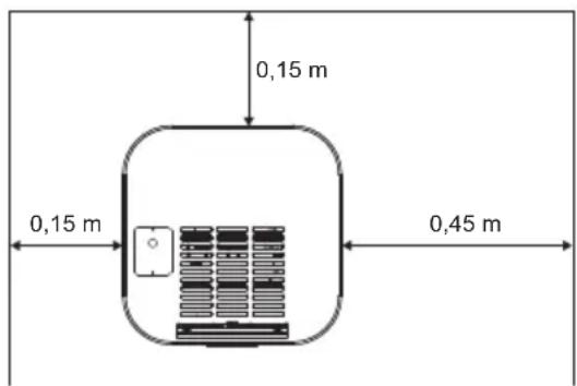
text_image
0,15 m 0,15 m 0,45 mNOTA
text_image
Acessórios3 Retire os suportes de envio.

text_image
Technical diagram showing a structural component with labeled parts ① and ②, including directional arrows indicating movement or force.natural_image
Technical line drawing of a mechanical valve assembly (no text or symbols)natural_image
Line drawing of a mechanical tool with threaded end and handle (no text or symbols)2 Instale a válvula de alívio de T&P na abertura marcada válvula de alívio de T&P.
Conexão do tubo de descarga da válvula de alívio de T&P

AVISO
natural_image
Pure mechanical component diagram showing a threaded pipe joint with a curved handle (no text or symbols)2 Fixe o tubo de descarga à saída da válvula de alívio de T&P. O tubo de descarga deve ser inclinado para baixo a partir da válvula para permitir a drenagem completa da válvula de alívio de T&P e do tubo de descarga.

text_image
Technical diagram showing mechanical assembly with labeled components and directional arrowsnatural_image
Technical line drawing of a mechanical pipe fitting with threaded end (no text or symbols)natural_image
Pure mechanical diagram of a pipe fitting with directional arrows, no text or symbols presentnatural_image
Simple line drawing of a mechanical component with an arrow pointing to a cylindrical base (no text or symbols)natural_image
Technical line drawing of a mechanical component with threaded shaft and circular base (no text or symbols)text_image
Diagram showing a mechanical component with numbered parts and directional arrows indicating motion or force.natural_image
Pure mechanical diagram showing a valve and nut assembly without any text, numbers, or symbolsFazer as conexões eléctricas

AVISO
text_image
16A30mA BR BL L1 L2text_image
Diagram showing hand gesture pointing to a circle with directional arrows, indicating rotation or movementtext_image
Diagram showing a hand interacting with a Wi-Fi icon, illustrating wireless signal transformationNOTA
Declaration of Conformity
EN

Hereby, LG Electronics declares that the radio equipment type Water Heater is in compliance with Directive 2014/53/EU. The full text of the EU declaration of conformity is available at the following internet address: http://www.lg.com/global/support/cedoc/cedoc#
UK DECLARATION OF CONFORMITY
EN

Hereby, LG Electronics declares that the radio equipment type Water Heater is in compliance with the relevant statutory requirements. The full text of the UK declaration of conformity is available at the following internet address: http://www.lg.com/global/support/cedoc/cedoc#
Wireless LAN Module Specifications
| Model | LCW-007 |
| Frequency Range | 2412 MHz - 2472 MHz |
| Output Power(Max) | IEEE 802.11b: 17.59 dBmIEEE 802.11g: 17.39 dBmIEEE 802.11n(HT20): 16.64 dBmIEEE 802.11n(HT40): 17.05 dBm |
Wireless function S/W version: V 1.0 / Безжична функция S/W версия: V 1.0 / Verze softwaru bezdrátové funkce: V 1.0 / Softwareversion til tràdløs funktion: V 1.0 / Drahtlosfunktion Software-Version: V 1.0 / 'Ekδοση λογισμικού ασύρματης λειτουργίας : V 1.0 / Versión de software de la función inalámbrica: V 1.0 / Juhtmevaba funktsiooni S/W versioon: V 1.0 / Langattoman toiminnon S/W versio: V 1.0 / Version S/W de la fonction sans fil : V 1.0 / Feidhm gan Sreang S/W leagan : V 1.0 / Verzija softvera bežične funkcije: V 1.0 / Vezeték nélküli funkció szoftver verzió: V 1.0 / Funzione Wireless S/W versione: V 1.0 / Belaidė funkcija S/W versija: V 1.0 / Bezvadu funkcijas programmas versija : V1.0 / Безжична функциja S/W верзија: V 1.0/ Funzjoni wireless verzjoni S/W : V 1.0 / Draadloze functie S/W-versie: V 1.0 / Tràdløs funksjon S/W versjon : V 1.0 / Oprogramowanie funkcji bezprzewodowej wer.: V 1.0 / Versão S/W da função sem fios: V 1.0 / Funcția wireless S/W versiunea : V 1.0 / Funkcia wireless S/W verzia: V 1.0 / Različica programske opreme za brezžično funkcijo: V1.0 / Funksioni wireless (pa lidhje kabllore) S/W versioni : V 1.0 / Verzija softvera bežične funkcije: V 1.0 / Tràdløs funtion S/W version : V 1.0 / Verzija softvera bežične funkcije: V 1.0
For consideration of the user, this device should be installed and operated with a minimum distance of 20 cm between the device and the body. / C orgled безопасността на потребителя, това устройство трябва да бъде инсталирано и оперирано от минимално разстояние 20 см между него и тялото. / S ohledem na uživatele by se toto zařízení mělo instalovat a provozovat tak, aby byla minimální vzdálenost mezi zařízením a tělem alespoň 20 cm. / Af hensyn til brugerens sikkerhed skal dette apparat installeres og betjenes med en minimumsafstand på 20 cm mellem apparatet og kroppen. / Zur Rücksichtnahme auf den Nutzer, sollte dieses Gerät mit einem Abstand von mindestens 20 cm zwischen dem Gerät und dem Körper installiert und betrieben werden. / Плнрофорика́ кяя то хрýστη, autíŋ η συσκευή θα πρέπει να εγκατασταθεί να λειτουργήσει με μια ελάχιστη απόσταση 20 см μεταξύ της συσκευής και του σώματος. / El usuario ha de tener en cuenta que el dispositivo deberá ser instalado y funcionar con una distancia mínima de 20 cm entre el mismo y el cuerpo. / Kasutaja peaks arvestama, et see seade tuleks paigaldada ja sellega töötada nii, et hoitakse minimaalne seadme ja keha vaheline vahemaa 20 cm juures. / Käyttäjän huomioimiseksi, laite tulee asentaa ja sitä tulee käyttää 20 cm:n minimietäisyyden päässä vartalosta. / À l'égard de l'utilisateur, cet appareil doit être installé et utilisé à une distance minimale de 20 cm entre l'appareil et le corps. / Ar mhaithe leis an úsáid, ba chóir an gléas seo a shuiteáil agus a oibriú ar a laghad 20 cm ó do chorp. / Za razmatranje korisnika, ovaj uređaj treba postaviti i njime upravljati s udaljenosti od najmanje 20 cm od tijela. / A felhasználónak vigyáznia kell, hogy ezt a készüléket úgy kell telepíteni és üzemeltetni egy legalább 20 cm távolságot biztosítsanak a készülék és a test között. / Si consiglia agli utenti di installare questo dispositivo ad una distanza minima di 20 cm tra il dispositivo e il corpo. / Vartotojas turi sumontuoti ir eksploatuoti šj jrenginį mažiausiai 20 cm. Nuo jrenginio ir korpuso. / Lietotāja izvērtēšanai, šī ierīce jāuzstāda un jādarbina, ievērojot minimālo distanci 20 cm starp ierīci un karkasu. / Заради грижата за корисникот, овој уред треба да се инсталира и да работи на минимална далечина од 20 см меѓу уредот и телото на корисникот. / Għall-konsiderazzjoni tal-utent, dan it-tagħmir għandu jiĝi installat u mħaddem b’distanza ta’ mhux inqas minn 20 ἐm bejn l-apparat u l-persuna. / Het is in het belang van de gebruiker dat dit apparaat geïnstalleerd en gebruikt wordt met een minimale afstand van 20 cm tussen het apparaat en het lichaam. / For hensynet til brukeren, bør denne enheten bli installert og brukt med en avstand på minimum 20 cm mellom apparatet og kroppen. / Zaleca się montaż oraz obsługę urządzenia z odległości co najmniej 20 cm. / Para consideração do utilizador, este dispositivo deve ser instalado e operado com uma distância mínima de 20 cm entre o dispositivo e o corpo. / Utilizatorul trebuie să Źină cont de faptul că acest dispozitiv trebuie instalat și utilizat cu o distanță minimă de 20 cm între dispozitiv și corp. / Poznámka pre používateľa: toto zariadenie by sa malo montovať a využívať v minimálnej vzdialenosti 20 cm medzi zariadením a telom. / Ob upoštevanju varnosti uporabnika je napravo treba namestiti in upravljati tako, da je med napravo ter telesom najmanj 20 cm. / Për konsideratën e përdoruesit, kjo pajisje duhet të instalohet dhe operohet nga një distancë minimale prej 20 cm mes pajisjes dhe trupit. / Korisnik treba da ima na umu da ovaj uređaj treba postaviti i njime upravljati sa udaljenosti od najmanje 20 cm od tela. / Med hänsyn till användaren, bör denna apparat installeras och drivas med en distans på åtminstone 20 cm mellan apparaten och kroppen. / Korisnik treba znati da ovaj uređaj treba postaviti i njime upravljati sa minimalne udaljenosti od 20 cm između uređaja i tijela.
Wireless LAN Module Specifications / Спецификации на безжичния LAN модул / Technické parametry modulu pro bezdrátovou sit' LAN / Wireless LAN modul Specifikationer / Wireless-LAN-Modul Technische Daten: / Продиаграфес аэруматнє мовадає LAN / Especificaciones del módulo LAN inalámbrico / Juhtmevaba LAN moduli tehnilised näitajad / Langattoman LAN-moduulin tekniset tiedot / Caractéristiques du module LAN sans fil / Sonraíochta modúil LAN gan sreang / Specifikacije bežičnog LAN modula / Vezetéknélküli LAN modul specifikáció / Specifiche del modulo LAN wireless / Belaidžio LAN modulio specifikacijos / Bezvada LAN moduła specifikácijas / Спецификации на бежичниот LAN модул / Specifikazzjonijiet tal-Wireless LAN Module. / Wireless LAN Module-specificaties / Spesifikasjoner for trádløs LAN-modul / Dane techniczne modułu sieci bezprzewodowej LAN / Especificações do módulo LAN sem fios / Specificații modul LAN Wireless / Špecifikácia bezdrótového modulu LAN / Specifikacije brežičnega LAN modula / Specifikimet e modulit LAN pa tel / Specifikacije modula za bežični LAN / Trádlös LAN Modul Specifikationer / Kablosuz LAN Modülü Teknik Özellikleri / Specifikacije bežičnog LAN modula
Model / Model / Model / Model / Modell / Movtélo / Modelo / Mudel / Malli / Modèle / Samhaltán / Model / Modell / Modello / Modelis / Modelis / Model / Mudell / Model / Model / Model / Model / Model / Model / Model / Model / Modeli / Model / Model / Model / Model
Frequency Range / Обхват на честотата / Frekvenčni rozsah / Frekvensområde / Frequency Range / Eúpoç συχνότητας / Rango de frecuencia / Sagedusala / Taajuusalue / Bande de fréquence : / Raon Minicióchta / Frekvencijski raspon / Frekvenciatartomány / Gamma di frequenza / Dažnio intervalas / Frekvenču diapazons / Фреквентен oncer / Medda tal-Frekwenza / Frequentiebereik / Frekvensområde / Zakres częstotliwości / Gama de frequência / Interval frecvență / Rozsah frekvencie / Frekvenčni razpon / Shtrirja e frekuencës / Opseg frekvencije / Frekvensområde / Frekans Araliği / Frekvencijski opseg
Output Power(Max) / Мощност (макс.) / Výstupní výkon (max.) / Udgangseffekt (Maks) / Ausgangsleistung (Max) / Iσχύς εξόδου (Μεγ.) / Potencia de salida (máx.) / Väljundvõimsus(Max) / Lähtöteho (maks.) / Puissance de sortie (Max) / (Uas)Cumhacht Asraon / Izlazna snaga (Maks) / Kimenõ teljesítmény (max) / Potenza di uscita (max.) / Išvesties galia (maks.) / Izejas jauda (maks.) / Излезна моїкност (макс.) / Produzzjoni ta' Energija (Mass) / Output -vermogen (Max) / Utstrålingseffekt (maks) / Moc wyjściowa (maks.) / Potência (Máx) / Putere ieşire (max.) / Výstupný výkon (maximálny) / Izhodna moč (maks.) / Fuqia e nxjerrjes (maks) / Izlazna snaga (maks) / Uteffekt(Max) / Çıkış Gücü (Maks.) / Izlazna snaga (maks)
(EN) Contains fluorinated greenhouse gases.
(BG) Съдържа флуорсъдържащи парникови газове.
(ES) Contiene gases fluorados de efecto invernadero.
(CS) Obsahuje fluorované skleníkové plyny.
(DA) Indeholder fluorholdige drivhusgasser.
(DE) Enthält fluorierte Treibhausgase.
(ET) Sisaldab fluoritud kasvuhoonegaase.
(EL) Περιέχει φθοριούχα αέρια του θερμοκηπίου.
(FR) Contient des gaz à effet de serre fluorés.
(IT) Contiene gas fluorurati ad effetto serra.
(LV) Satur fluorētas siltumnīcefekta gāze,
(LT) Sudétyje yra fluorintų šiltnamio efektą sukeliančių duju.
(HU) Fluortartalmú üvegházhatású gázokat tartalmaz.
(MT) Fih gassijiet fluworurati b'effett ta' serra
(NL) Bevat gefluoreerde broeikasgassen.
(PL) Zawiera fluorowane gazy cieplarniane-
(PT) Contém gases fluorados com efeito de estufa-
(RO) Conține gaze fluorurate cu efect de seră.
(SK) Obsahuje fluórované skleníkové plyny
(SL) Vsebuje fluorirane toplogredne pline.
(FI) Sisältää fluorattuja kasvihuonekaasuja-
(SV) Innehåller fluorerade växthusgaser-
(NO) Inneholder fluorholdige klimagasser.
(IS) Inniheldur flúraðar gróðurhúsalofttegundir-
(HR) Sadržava fluorirane stakleniČke plinove
Hermetically sealed equipment
※ R134a GWP:1430 (GWP/PRG / GWP/PRP /GWP/GWP)
※ t-CO₂ eq = F-gas (kg) × GWP/1000

LG
Life's Good