SW4 POE - Network switch DELTA DORE - Free user manual and instructions
Find the device manual for free SW4 POE DELTA DORE in PDF.
| Product type | 5-port PoE network switch (4 PoE ports + 1 uplink port) |
| Brand | Delta Dore |
| Model | SW4 POE |
| Dimensions | 105 mm × 28 mm × 84 mm |
| Weight | Approximately 200 g (estimated) |
| Power supply | Mains adapter 230V AC, output 48V DC / 1.35 A |
| PoE standards | IEEE 802.3af (PoE) and IEEE 802.3at (PoE+) |
| Total PoE power | 60 W max, up to 30 W per port |
| Extended mode | Yes, up to 300 m with Cat.6 cable (10 Mbps speed) |
| Ports | 4 PoE ports (ports 1-4) + 1 uplink port (port 5) |
| Speeds | 10/100 Mbps (Fast Ethernet) |
| Operating temperature | -10°C to 40°C |
| Installation | Plug & Play, no configuration, can be mounted in VDI enclosure |
| Maintenance and cleaning | Disconnect power before cleaning, keep the device clean, dry and well ventilated |
| Safety | Mandatory grounding, do not open the casing, avoid dust and moisture |
| Spare parts and repairability | Mains adapter supplied, user non-removable parts |
Frequently Asked Questions - SW4 POE DELTA DORE
User questions about SW4 POE DELTA DORE
0 question about this device. Answer the ones you know or ask your own.
Ask a new question about this device
Download the instructions for your Network switch in PDF format for free! Find your manual SW4 POE - DELTA DORE and take your electronic device back in hand. On this page are published all the documents necessary for the use of your device. SW4 POE by DELTA DORE.
USER MANUAL SW4 POE DELTA DORE
text_image
Diagram of a network equipment setup showing server rack, router, and connected devices with labeled components.5.2 Raccordement
Technical characteristics
| Interfaces 10/100 Mbps RJ45 port 5 | |
| Priority port Port 1 | |
| Energy Store and transfer Supported | |
| MAC table 1 k | |
| MAC learning Automatic identification | |
| Switching capacity 1 Gbps | |
| PoE power PoE standard IEEE 802.3af, IEEE 802.3at | |
| PoE power supply mode Supports the 8-pin power supply, pins 1,2,3,6 and pins 4,5,7,8 can be supplied simultaneously | |
| PoE port 1 - 2 - 3 - 4 | |
| Max. port output 30 W | |
| Max. total output 60 W | |
| Extended mode | |
| Lightning protection classification | Port |
| Lightning-protected power supply | |
| Electric power | |
| Operating temperature | |
| Storage temperature | |
| Max. transmission speed | |
| Network | |
 |
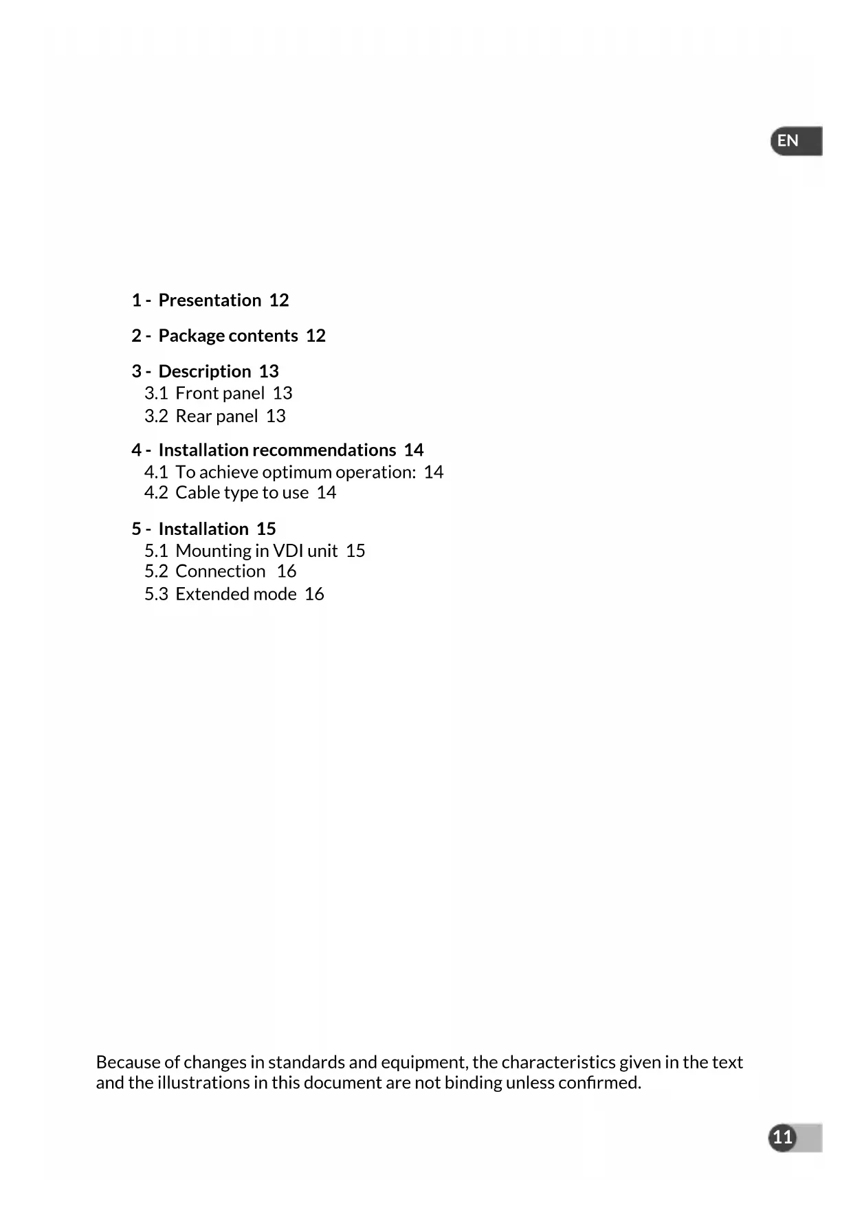
1 - Presentation 12
2 - Package contents 12
3 - Description 13
3.1 Front panel 13
3.2 Rear panel 13
4 - Installation recommendations 14
4.1 To achieve optimum operation: 14
4.2 Cable type to use 14
5 - Installation 15
5.1 Mounting in VDI unit 15
5.2 Connection 16
5.3 Extended mode 16
Because of changes in standards and equipment, the characteristics given in the text and the illustrations in this document are not binding unless confirmed.
1 - Presentation
The PoE SW4 can supply power, via the Ethernet RJ45 link, to the TYCAM 1100 INDOOR and TYCAM 2100 OUTDOOR cameras or any PoE (Power over Ethernet) device (4 max.) compatible with standards PoE 802.3af and PoE 802.3at.
The power supply and data can transit simultaneously by ports 1, 2, 3 and 4.
The maximum power: for all 4 outputs is 60 W.
The PoE SW4 supports the Extend mode. The data transmission distance can reach 300 metres with the extended mode and a category 6 Ethernet cable.
This is a plug & play device and requires no special configuration.
2 - Package contents
① PoE SW4
② 230 V power supply adaptor.

natural_image
Illustration of a DELTA DORE network switch device with ports and indicator lights (no text or symbols on the device body)
natural_image
Line drawing of a device with two cables and connectors, no text or symbols present3 - Description

text_image
① ③ ④ ① 12345 ② ⑤ ⑥EN
3.1 Front panel
| LED Status Description | ||
| 1PWR | On steady The device is properly connected to the mains power. | |
| Off The device is poorly connected or not connected to the mains power. | ||
| 2PoE-MAX | On steady The PoE power reaches its lower limit value (6 W). | |
| Flashing The PoE power reaches its maximum (60 W). | ||
| Off The PoE power supply operates correctly and the PoE power available is greater than 6 W. | ||
| 3LINK-ACT | On steady The corresponding port is correctly connected. | |
| Flashing Transmission or reception of data on the port | ||
| Off The corresponding port is not properly connected or is not connected. | ||
| 4PoE status | On steady The corresponding port is connected and correctly supplies power to the PoE peripheral device. | |
| Flashing The PoE output of the corresponding port exceeds 30 W. | ||
| Off No POE compatible peripheral is connected. | ||
⑤ PoE ports - 1, 2, 3, 4.
⑥ Port 5 (UPLINK) router
3.2 Rear panel
⑦ Extended mode selector. Refer to § 5.3.
⑧ Earth connection: Connection of the PoE SW4 unit to the earth connection.
⑨ Power outlet: Use the 230 V power supply adapter supplied.

text_image
OFF DIN EXEING PORT 1-4 PWR DC 48V4 - Installation recommendations
4.1 To achieve optimum operation:
• Install the PoE SW4 indoors in a dry, well-ventilated, dust-free environment.
- Ensure that the device is correctly fitted to a rack or placed on a stable surface.
- Switch off the device before connecting or disconnecting the connected peripheral devices.
- Antistatic precautions: Dust can lead to electrostatic adsorption. To protect the device against damage from static electricity, keep the environment of the device clean, dry and well ventilated (regular dusting is required).
- Disconnect the mains supply from the device when you are performing the cleaning operations.
- Use the power supply adaptor included to supply power to the device. Ensure that the input voltage matches the value stated on the device label.
- Connect the device power supply after making all the other connections.
- Do not open the device unit.
- Place the device away from strong currents.
- Ensure that the device is correctly earthed.
- Do not obstruct the ventilation slots, maintain a free space of 10 cm on each side of the device.
- Do not place any heavy or large object on the device.
- For equipment connected to the power grid, the socket outlet must be installed close to the equipment and readily accessible.
4.2 Cable type to use
Choose the appropriate cable according to the distance between the equipment to connect and the PoE SW4.
- Up to 200 metres: Use a category 5 Ethernet cable.
- From 200 to 300 metres: Use a category 6 Ethernet cable.
5 - Installation
5.1 Mounting in VDI unit
You can install the PoE SW4 in a VDI communication unit (Voice, Data, Image).
- Respect a distance of 10 cm on each side of the ventilation slots.
- Connect the PoE SW4 unit to the earth connection.

text_image
RouterEN
5.2 Connection
① Connect port 5 (UPLINK) to your router using an Ethernet RJ45 cable.
② Connect your camera to port 1 (PoE port has priority) with a category 5 or above Ethernet cable. If necessary, you can connect any other compatible peripheral device (camera, IP phone, wireless access point, etc.) to ports 2, 3 and 4.
③ Connect the 230 V power supply adapter supplied.

text_image
LINK/ACT PoE PWR PoE-MAX 1 2 PoE 3 4 UPLINK ① RJ45 RJ45RJ45 Internet5.3 Extended mode

| OFF | Ports 1-4: 100 metres/100 MB |
| ON | Ports 1-4: from 100 metres to 300 metres/10 MB |
Note
To ensure the performance of the extended mode, use a Category 6 Ethernet cable.
EN
Technische Daten
natural_image
Illustration of a Delta DORE network switch with two labeled components (① and ②), showing internal ports, cable, and port connections.3 - Beschreibung

text_image
① ③ ④ ① ② 12345 ⑤ ⑥3.1 Vorderseite
text_image
Diagram of an electrical or network device setup showing a server rack with ports, a router, and connected modules.DE
5.2 Anschluss
text_image
OFF ON FOUNTING PORT 1.4 ⑦ ⑧ PWR DC 48V ⑨natural_image
Front view of a Delta DORE network switch device with ports and indicator lights (no text or symbols on the device body)
natural_image
Line drawing of a battery pack connected to two cables (no text or symbols)3 - Descripción

text_image
① ③ ④ ① 12345 ② ⑤ ⑥3.1 Parte frontal
text_image
Diagram of an electrical or network device setup showing a rack-mounted server with ports, a router, and connected to a camera.ES
5.2 Conexión
text_image
OFF RUN Extinct PORT 1.4 PWR DC 48Vtext_image
Diagram of a server rack with labeled components including an Ethernet, router, and connected devices5.2 Podłączenie
natural_image
Front view of a Delta DORE network switch device with four Ethernet ports and indicator lights (no text or symbols on the device body)
natural_image
Line drawing of a device with two cables and connectors, no text or symbols present3 - Omschrijving

text_image
① ③ ④ 12345 ② ⑤ ⑥NL
3.1 Voorzijde
text_image
OFF EXTNC PORT 1.4 PWR DC 48Vtext_image
Diagram of an electrical or network device setup showing a rack-mounted server with ports, connected to a camera and a separate monitor.NL
5.2 Aansluiting
natural_image
Front view of a DELTA DORE network switch device with four Ethernet ports and indicator lights (no text or symbols on the device body)
natural_image
Line drawing of a battery pack connected to two cables with connectors (no text or symbols)3 - Beskrivelse

text_image
① ③ ④ ① 12345 ② ⑤ ⑥3.1 Forside
natural_image
Illustration of a DELTA DORE network switch device with ports and indicator lights (no text or symbols on the device body)
natural_image
Line drawing of a device with two cables and connectors, no text or symbols present3 - Kuvaus