RF 4890 - Receiver DELTA DORE - Free user manual and instructions
Find the device manual for free RF 4890 DELTA DORE in PDF.
| Brand | Delta Dore |
| Model | RF 4890 |
| Product type | Radio receiver for heating/air conditioning system |
| Power supply | 230 V~ 50 Hz |
| Dimensions (L x W x H) | 80 x 80 x 25 mm |
| Weight | 100 g |
| Radio frequency | 868 MHz (proprietary protocol) |
| Range | Up to 100 m in open field |
| LED indicators | Left LED (pairing), right LED (mode) |
| Main functions | Receiving thermostat commands, relay control for heating/air conditioning, frost protection mode |
| Compatibility | Delta Dore Tybox 5101, Tybox 5300, Tybox 5701 FP thermostats |
| Operating temperature | 0 °C to 50 °C |
| Protection rating | IP30 (indoor use) |
| Care and cleaning | Clean with a soft, dry cloth. Do not use abrasive cleaners or solvents. |
| Installation | Wall mounting via screws or adhesive. Electrical connection by a professional. |
| Safety | Do not expose to moisture or water splashes. Disconnect before any intervention. |
| Spare parts and repairability | No spare parts available. In case of failure, contact customer service. |
| General information | The RF 4890 receiver allows you to control a heating or air conditioning device from a Delta Dore radio thermostat. It must be paired with a compatible transmitter before use. |
Frequently Asked Questions - RF 4890 DELTA DORE
User questions about RF 4890 DELTA DORE
0 question about this device. Answer the ones you know or ask your own.
Ask a new question about this device
Download the instructions for your Receiver in PDF format for free! Find your manual RF 4890 - DELTA DORE and take your electronic device back in hand. On this page are published all the documents necessary for the use of your device. RF 4890 by DELTA DORE.
USER MANUAL RF 4890 DELTA DORE
Your Tybox 5101 is paired to a receiver. You must identify this receiver in order to consult the corresponding instructions:
| RF 6050+ Consult the | Tybox 5300 web instructions |
| RF 6000+ Consult the | Tybox 2300 web instructions |
| RF 6700 FP Consult the | Tybox 5701/5702 FP web instructions |
| RF 6000 (Tybox 5100) | Consult these instructions |
| RF 6050 (Tybox 5200) | Consult these instructions |
| RF 6200 Consult the Tybox 5150 web manual | |
| Delta 8000 RF Consult | the Delta 8101 Pack web instructions |
| Other receivers | Consult these instructions |
There are two versions of the Tybox 5101 transmitter.
To find out the transmitter version, press the "mode" button for several seconds until the 1st configuration menu appears: CF00 or CF01.
| First version |  |  | Access the instructions |
| Second version |  |  | Access the instructions |
Tybox 5101
EN For detailed instructions: scan the QR code.
- Setup
- Pairing,
- Advanced features,
- Help.
EN ① Set the receiver to association mode: (refer to the user guide).
② On the Tybox, briefly press a button to wake up the display, then press and hold both the mode and + buttons for 3 seconds. The screen will display rF00. Release.
3 Press briefly on+. The screen flashes until rF is displayed depending on the number of associated receivers (eg. rF01 for a single receiver, rF02 for 2 receivers etc.).
4 Check that the LED of the receiver(s) is no longer flashing. To exit the mode, briefly press the mode and + buttons simultaneously.
EN 1 Press any button to activate the display The current mode is displayed: On = Thermostat running, OFF = Stop. To switch from one mode to another, press mode.
2 From On mode, wait a few seconds to display the set-point temperature and change it using + or -. Validation after 2 seconds if no buttons are pressed.
EN ① Press any button to activate the display. To switch from Heating (☀) to Cooling (❄) press mode twice.
The current mode is displayed: On = Thermostat running, OFF = Stop. To switch from one mode to another, press mode.
2 From On mode, wait a few seconds to display the set-point temperature and change it using + or -.
Validation after 2 seconds if no buttons are pressed.
1.1 Location....3
1.2 Wall mounting....3
1.3 Mounting on a base 3
- Wireless Association....4
- Configuring your device 4
Menu CF00 Backlit display....5
Menu CF01 - Correcting the temperature measured....5
Menu CF02 Locking the buttons....5
Menu CF03 RT2012 Solar optimisation....5
- Link the thermostat to the solar optimisation of an RT2012 manager 6
- Technical specifications .... 6
Use
- Description 7
- Set point settings 7
2.1 Heating/Cooling....7
2.2 Heating....7
2.3 Air conditioning....7
- Open window detection....8
- Troubleshooting 8
4.1 Changing batteries....8
4.2 Frequently Asked Questions (FAQ)......8
INSTALLATION
1. Installing the transmitter
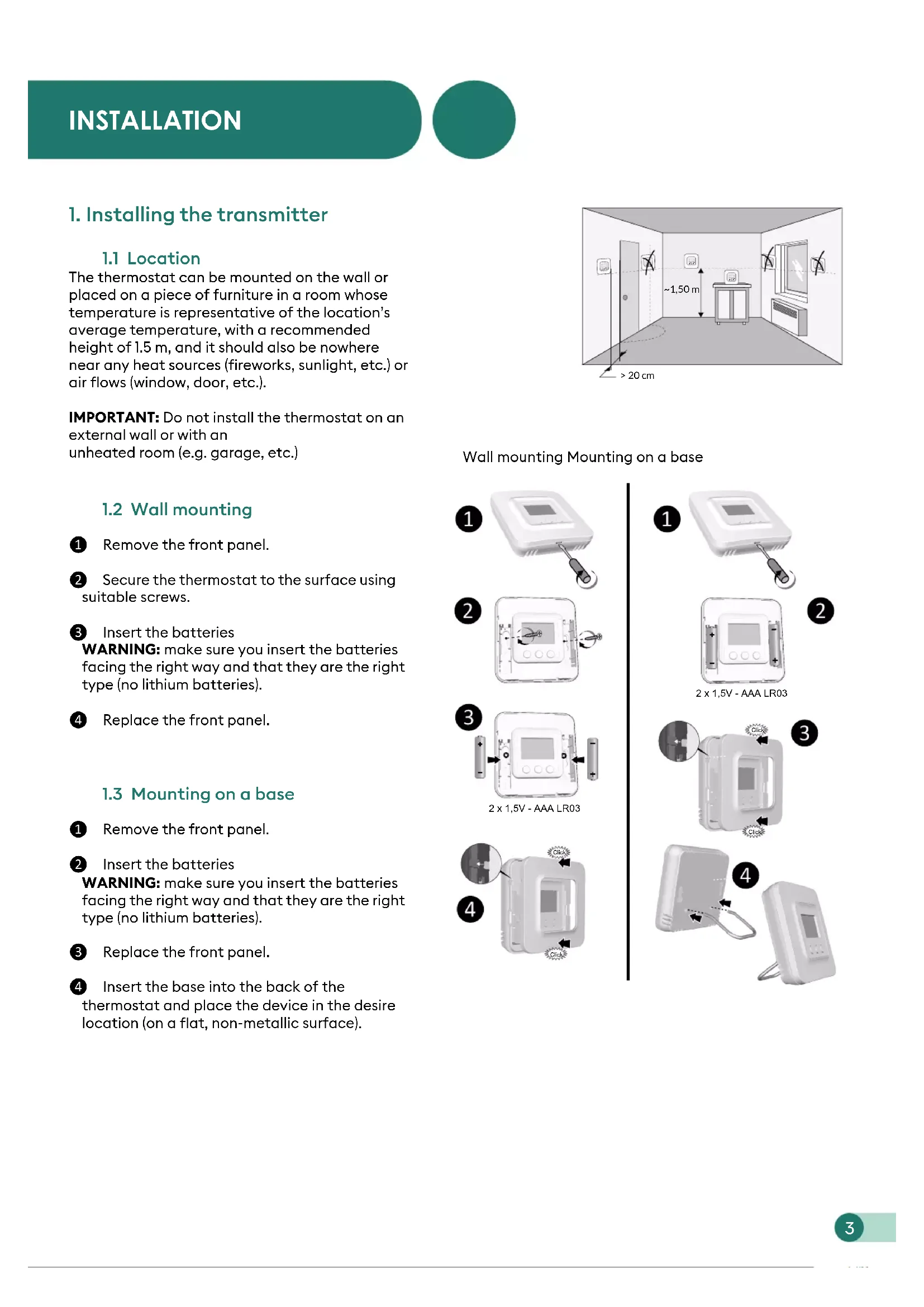
1.1 Location
The thermostat can be mounted on the wall or placed on a piece of furniture in a room whose temperature is representative of the location's average temperature, with a recommended height of 1.5 m, and it should also be nowhere near any heat sources (fireworks, sunlight, etc.) or air flows (window, door, etc.).
IMPORTANT: Do not install the thermostat on an external wall or with an unheated room (e.g. garage, etc.)
1.2 Wall mounting
1 Remove the front panel.
2 Secure the thermostat to the surface using suitable screws.
③ Insert the batteries
WARNING: make sure you insert the batteries facing the right way and that they are the right type (no lithium batteries).
4 Replace the front panel.
1.3 Mounting on a base
① Remove the front panel.
② Insert the batteries
WARNING: make sure you insert the batteries facing the right way and that they are the right type (no lithium batteries).
③ Replace the front panel.
4 Insert the base into the back of the thermostat and place the device in the desire location (on a flat, non-metallic surface).

text_image
-1,50 m > 20 cmWall mounting Mounting on a base

natural_image
White electronic device with a square display and a USB cable inserted, labeled with number 1 (no text or symbols on the device itself)
text_image
2
text_image
3 2 x 1,5V - AAA LR03
text_image
4 Click Click
text_image
1 2 2 x 1,5V - AAA LR03
text_image
Click Click
natural_image
Two electronic devices with cables and a digital display, shown from different angles (no text or symbols visible)2. Wireless Association

text_image
① 192℃ df 0 - mode + - mode + ② rF00 rF00…rF01 OFF rF01 185℃ - mode + 4① Set the receiver to association mode: (refer to the user guide).
② On the Tybox, briefly press a button to wake up the display, then press and hold both the mode and + buttons for 3 seconds. The screen will display rF00. Release.
3 Press briefly on +. The screen flashes until rF is displayed depending on the number of associated receivers (eg. rF01 for a single receiver, rF02 for 2 receivers etc.).
4 Check that the LED of the receiver(s) is no longer flashing. To exit the mode, briefly press the mode and + buttons simultaneously.
3. Configuring your device

text_image
192°C 185°C CF00 ... CF01 ... CF03 ● > 5s - + - mode mode ● > 5s① Press any button to activate the screen.
② Press mode for 10 seconds until CF00 is displayed.
3 Press + or - to adjust the setting, and on mode to move to the next menu.
4 Press mode for 5 seconds to exit the configuration menu or, after a period of 2 seconds without activity, the Tybox validates the change of parameter and returns to standby.
3. Configuring your device
Menu CF00 Backlit display
Default value: activated
| ☐ | Deactivated |
| I | Activated (automatic switch-off) |
Menu CF01 - Correcting the temperature measured

text_image
CF01 + +5°C - 0.0°C - -5°CThis menu is used to correct any difference you have noticed between the displayed temperature and the measured temperature.
Example: If the temperature displayed by the device is 19^ C and the measured temperature is 20^ C, input +1°C then confirm using OK.
Adjusts from -5^ to 5^ , in increments of 0.1^ .
In order to change this setting, the unit must have been running for at least 2 hours beforehand. Default setting: 0°C
Menu CF02 Locking the buttons

text_image
CF02 + - 01 00This menu allows you to prohibit any changes (settings, set point, mode).
| 0 | No locking |
| 1 | Locking active |
If locked, the screen will display “----”. To temporarily unlock, simultaneously press and hold the + and - buttons for 5 seconds.
Please leave the setting at 00 unless the Tybox is being used on its own (without a receiver) in solar optimisation mode with an RT2012 manager (see §4).
Depending on the receiver to which the Tybox is connected, other CF menus may appear: refer to the pack instructions.
4. Link the thermostat to the solar optimisation of an RT2012 manager

flowchart
graph LR
    A["192°C"] --> B["mode + >3s"]
    B --> C["rF00"]
    C --> D["- +"]
    D --> E["rF--"]
    E --> F["mode + >3s"]
    F --> G["rF00"]
    G --> H["- +"]
    H --> I["rF01"]
    I --> J["mode + >3s"]
    J --> K["192°C"]
1 Set the power manager to «Association a room sensor» mode (refer to its user guide).
② On the Tybox, briefly press a button to wake up the display, then simultaneously press and hold the Mode and + buttons for 3 seconds. The screen displays rF00 or rF01 depending on whether or not a receiver is associated. Release the button.
3 Simultaneously press the + and - buttons for 3 seconds. The screen will display rF-- For 1 to 2 seconds then automatically returns automatically to rF00 or rF01. The manager then confirms the association.
4 To exit and return to the temperature display, Simultaneously press (short press) + and -.
5. Technical specifications
TYBOX 5101 transmitter
• Power supply using 2 batteries: 2x1.5V Alkaline - Type LR03-AAA
• Class III insulation
• X3D transmission frequency: 868.7 MHz to 869.2 MHz
• Maximum wireless power < 10 mW
• Category II receiver
- Wireless range of 300 metres outside, varies depending on the associated equipment (the range can vary depending on the installation conditions and the electromagnetic environment).
• Wall-mounted or on base
• Dimensions: 80 x 84 x 21 mm
• Protection Class: IP 20
• Installation in an environment with normal pollution levels
• Storage temperature: -10°C /+70°C
- Operating temperature from -10^ / +40^
1. Description

text_image
DEFG ON 190°C - mode + A B CⒶ Temperature display
B Select the mode
© Adjustment buttons
(D) Request in progress
*Depending on the installation
⑤ Heat mode*
F Air conditioning mode*
G Battery level indicator
2. Set point settings
2.1 Heating/Cooling

flowchart
graph TD
    A["19.2°C"] --> B["OFF"]
    B --> C["On"]
    D["OFF"] --> E["×2 mode"]
    E --> F["Hand icon"]
    G["Off"] --> H["×2 mode"]
    H --> I["Hand icon"]
2

2

① Press any button to activate the display screen. To switch from Heating (to Cooling (), press mode twice.
The current mode is displayed:
On = Thermostat on, OFF = Stop.
To switch from one mode to another, press mode.
② From On mode, wait a few seconds to display the set-point temperature and change it using + or -.
Validation after 2 seconds if no buttons are pressed.
2.2 Heating

text_image
19.2°C OFF On2

2.3 Air conditioning

text_image
1 192°C OFF* On* 2 240°C - modemode① Press any button to activate the display screen. The current mode is displayed:
On = Thermostat on, OFF = Stop.
To switch from one mode to another, press mode.
② From On mode, wait a few seconds to display the set-point temperature and change it using + or -.
Validation after 2 seconds if no buttons are pressed.
3. Open window detection

You have paired a window/door magnetic contact with your installation. If an open window/door is detected, the display shows OPEn. The heating is in frost protection mode. The air conditioning is off.
4. Troubleshooting
4.1 Changing batteries
- The symbol appears.
You have approximately 1 month to replace them (two 1.5 V alkaline batteries, either LR03 or AAA).
WARNING: make sure you insert the batteries facing the right way and that they are the right type (no lithium batteries).


natural_image
White electronic device with a digital display and a black screwdriver inserted into it (no visible text or symbols)
text_image
2 x 1,5V - AAA LR034.2 Frequently Asked Questions (FAQ)
• The screen displays: 000
Your Tybox transmitter is temporarily awaiting feedback.
• The screen displays:
Your Tybox transmitter has just "woken up" (exit standby).
• The screen displays:
See Chapter 3 "Configuration", paragraph "CF02".
• The screen displays "dF 0".
Your Tybox transmitter is not associated to a heating receiver.
• The screen displays "dF 9".
Wireless fault during wireless communication (turning on, sending a command).
• The screen displays "dF22".
You are controlling several receivers that are not in the same operating mode (heating or air conditioning). Press mode to synchronise them, the dF22 display disappears.
- You do not have access to the settings:
- The buttons are locked. The screen displays “----”.
To temporarily unlock (until the next standby time), simultaneously press and hold the + and - buttons for 5 seconds.

flowchart
graph LR
    A["18.5°C"] --> B["- mode +"]
    B --> C["lock"]
    C --> D[">5s"]
    D --> E["18.5°C"]
To unlock them permanently, go to the CF02 configuration menu.
- Your Tybox is associated to a receiver and CF03 = 1. Set CF03 to 0.
END OF TYBOX 5101 WEB INSTRUCTIONS 2nd VERSION.
Tybox 5101
EN For detailed instructions: scan the QR code.
- Setup
- Pairing,
- Advanced features,
- Help.
EN ① Set the receiver to association mode: (refer to the user guide).
② On the Tybox, briefly press a button to wake up the display, then press and hold both the mode and + buttons for 3 seconds. The screen will display rF00. Release.
3 Press briefly on +. The screen flashes until rF is displayed depending on the number of associated receivers (eg. rF01 for a single receiver, rF02 for 2 receivers etc.).
4 Check that the LED of the receiver(s) is no longer flashing. To exit the mode, briefly press the mode and + buttons simultaneously.
EN 1 Press any button to activate the display. The current mode is displayed:
On = Thermostat running, OFF = Stop.
To switch from one mode to another, press mode.
2 From On mode, wait a few seconds to display the set-point temperature and change it using + or -.
Validation after 2 seconds if no buttons are pressed.
EN ① Press any button to activate the display. To switch from Heating (☀) to Cooling (❄) press mode twice.
The current mode is displayed: On = Thermostat running, OFF = Stop. To switch from one mode to another, press mode.
2 From On mode, wait a few seconds to display the set-point temperature and change it using + or -.
Validation after 2 seconds if no buttons are pressed.
- Boiler Plus compliant

Raccordement / Connection / Anschluss / Collegamento

text_image
1 OFF 230V~ 50 Hz 2 TYBOX 5101 TYBOX 5100 TYBOX 5200 TYBOX 5150 205 605 + RF 6000 205 605 + RF 6050 205 605 + RF 6200 Lg : 1m 5A 1 2 3 4 Max. L N L ① Noir / Black / Schwarz / Nero ② Gris / Grey / Grau / Grigio ③ Bleu / Blue / Blau / Blu ④ Marron / Brown / Braun / Marrone 5A - 230V- 1 2 3 4 5 6 230V~ 50 Hz N 5A - 230V- Th 12345 678 Change-over 230V~ 50 Hz 5A - 230V~ 12345 678 Th Cool Th Heat
When the device is switched on, the right indicator light flashes: Mode selection (press and release) /
EN ● Press and hold the receiver button for 3 seconds until the LED flashes. Release.
② Press and hold the mode and + buttons on the TYBOX 5101 simultaneously for 3 seconds.
The screen will display rF00. Release.
- Press + briefly. The screen will flash, then display rF01.
- Make sure that the receiver LED has stopped flashing. To exit the mode, press the mode and + buttons simultaneously.
① Switch on the installation.
Press and hold the receiver button for 3 seconds until the LED flashes. Release.
② Send the association command to the transmitter (see user guide).
- Make sure that the receiver LED has stopped flashing. The products are now associated.

Associer le thermostat pour l'optimisation solaire / Associate the thermostat for solar optimisation / Zuordnen des Raumthermostals für die Solaroptimierung / Associare il termostato per l'optimizzazione solare

text_image
1 19.7℃ mode 2 rF00 rF01 3 rF-- 4 19.7℃
① Set the energy manager to "Associate a room sensor" mode (see user guide).
② Press and hold the mode and + buttons on the TYBOX 5101 simultaneously for 3 seconds until it displays rF01 (rF00 if TYBOX 5101 is used alone)
③ Press and hold the - and - buttons simultaneously for 3 seconds.
The screen will display rF--
④ The mode is automatically exited.

① Press any button to activate the display screen. The current mode will be displayed: ON = start authorisation, ⏻ = shutdown. To change the mode, press mode.
② From the ON mode, press the '+' or '-' buttons to display the temperature setting and change it.
③ Press on mode or wait 5 seconds to exit. When switching over from the ⏻ mode to the ON mode, the setting's default value is restored: 20°C.

Indicates that the system is in Frost Protection mode (10°C non modifiable).
Example: open window


text_image
19.7°C - mode + → ---- → >10s → 195°C
Changer les piles / Replace the batteries / Batterien ersetzen / Sostituire le pile

text_image
19.7c 2 x 1,5V - AAA LR03
Effacer les associations / Remove the associations / Zuordnungen löschen / Cancellare le associazioni
Sur le récepteur / On the receiver / Am Empfänger / Sul ricevitore

flowchart
graph LR
    A["Input: 3s"] --> B["Time >20s"]
    B --> C["Output: RESET OK"]
    subgraph Time_1
        D["Neat... Neat... Neat..."]
        E["Neat... Neat... Neat..."]
    end
    subgraph Time_2
        F["Neat... Neat... Neat..."]
        G["Neat... Neat... Neat..."]
    end
    subgraph Time_3
        H["Neat... Neat... Neat..."]
        I["Neat... Neat... Neat..."]
    end
    subgraph Time_4
        J["Neat... Neat... Neat..."]
        K["Neat... Neat... Neat..."]
    end
    style A fill:#f9f,stroke:#333
    style B fill:#ccf,stroke:#333
    style C fill:#cfc,stroke:#333
    style D fill:#fcc,stroke:#333
    style E fill:#cff,stroke:#333
    style F fill:#ffc,stroke:#333
    style G fill:#ffc,stroke:#333
    style H fill:#fcc,stroke:#333
    style I fill:#fcc,stroke:#333
    style J fill:#fcc,stroke:#333
    style K fill:#fcc,stroke:#333
    style L fill:#fcc,stroke:#333
    style M fill:#fcc,stroke:#333
    style N fill:#fcc,stroke:#333
    style O fill:#fcc,stroke:#333
    style P fill:#fcc,stroke:#333
    style Q fill:#fcc,stroke:#333
    style R fill:#fcc,stroke:#333
    style S fill:#fcc,stroke:#333
    style T fill:#fcc,stroke:#333
    style U fill:#fcc,stroke:#333
    style V fill:#fcc,stroke:#333
    style W fill:#fcc,stroke:#333
    style X fill:#fcc,stroke:#333
    style Y fill:#fcc,stroke:#333
    style Z fill:#fcc,stroke:#333
Sur le thermostat / On the thermostat / Am Raumthermostat / Sul termostato

text_image
19.7°C mode + F01 - F00 RESET OK
Aide / Troubleshooting / Hilfe / Aiuto

Temporarily indicates that there has been a wireless transmission conflict and that the command was not sent. Repeat the operation.
Indicates that no product is associated. Refer to § Association.