
PowerConnect JSRX240 - Network Equipment DELL - Free user manual and instructions
Find the device manual for free PowerConnect JSRX240 DELL in PDF.
| Product Type | Services Gateway for network |
| Brand | Dell |
| Model | PowerConnect J-SRX240 (regulatory number SRX240) |
| Model Variants | J-SRX240B (512 MB DDR, without PoE, without voice), J-SRX240H (1 GB DDR, without PoE, without voice), J-SRX240H-POE (1 GB DDR, PoE 150W, without voice), J-SRX240H-P-MGW (1 GB DDR, PoE 150W, integrated voice) |
| Network ports | 16 Gigabit Ethernet ports (ge-0/0/0 to ge-0/0/15) |
| Administration ports | 1 Console port (RJ-45), 1 Ethernet management port (on front panel?) |
| Power over Ethernet (PoE) | On J-SRX240H-POE and J-SRX240H-P-MGW models: 150 W on 16 ports |
| DDR Memory | 512 MB (J-SRX240B) or 1 GB (other models) |
| Voice interfaces | On J-SRX240H-P-MGW: 2 FXS ports, 2 FXO ports (RJ-11) |
| Mini-PIM slots | 2 slots for mini-PIM modules |
| Buttons and indicators | Power button, Reset Config button, LEDs: ALARM (orange/red), POWER (green), STATUS (green), HA, mPIM |
| Power connector | Standard mains connector, grounding via 6-32 UNC screw |
| Default configuration | Interface ge-0/0/0 in untrust zone (DHCP client), interfaces ge-0/0/1 to ge-0/0/15 in trust zone (DHCP server, subnet 192.168.1.0/24, gateway IP 192.168.1.1) |
| Main functions | Secure routing, firewall, VPN, NAT, management via J-Web web interface or CLI |
| Management | J-Web web interface (http://192.168.1.1), serial console (9600 8-N-1) |
| Power supply | Mains, use of surge protection device recommended |
| Safety | Mandatory grounding with 14 AWG solid wire and TV14-6R ring terminal |
| Operating conditions | Standard ambient temperature, follow grounding and power supply instructions |
| Weight and dimensions | Not specified in the manual, refer to Dell website |
Frequently Asked Questions - PowerConnect JSRX240 DELL
User questions about PowerConnect JSRX240 DELL
0 question about this device. Answer the ones you know or ask your own.
Ask a new question about this device
Download the instructions for your Network Equipment in PDF format for free! Find your manual PowerConnect JSRX240 - DELL and take your electronic device back in hand. On this page are published all the documents necessary for the use of your device. PowerConnect JSRX240 by DELL.
USER MANUAL PowerConnect JSRX240 DELL
Dell PowerConnect J-Series J-SRX240 Services Gateway Quick Start
Use the instructions in this quick start to help you connect the Dell PowerConnect J-Series J-SRX240 Services Gateway to your network. For details, see the J-SRX240 Services Gateway Hardware Guide at http://support.dell.com/manuals. (Regulatory model number SRX240)
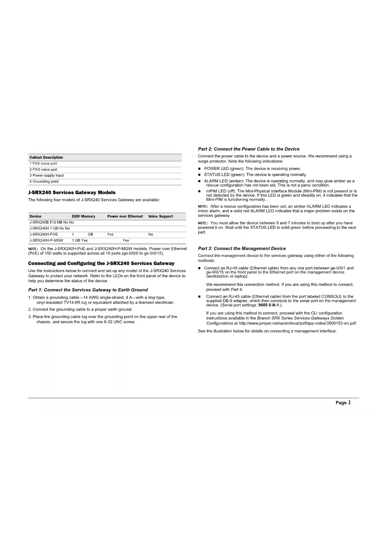
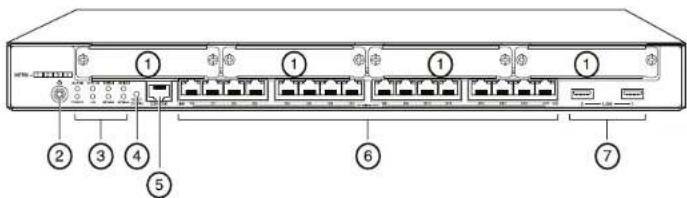
J-SRX240 Services Gateway (J-SRX240B, J-SRX240H) Front Panel
Callout Description Callout Description
| 1 Mini-PIM slots 5 Console port | |
| 2 Power button 6 Gigabit Ethernet (0/0 to 0/15) | |
| 3 LEDs (ALARM, POWER, STATUS, HA, mPIM) | 7 USB ports |
| 4 Reset Config button | |
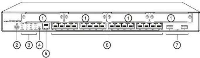
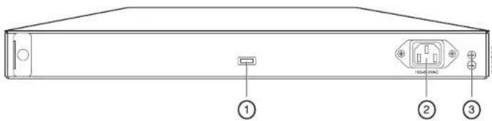
J-SRX240 Services Gateway (J-SRX240B, J-SRX240H, J-SRX240H-POE) Back Panel
Callout Description
| 1 Cable tie holder |
| 2 Power supply input |
| 3 Grounding point |
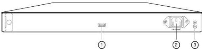
J-SRX240 Services Gateway with Integrated Convergence Services (J-SRX240H-POE, J-SRX240H-P-MGW) Front Panel
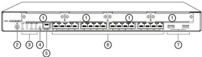
Callout Description Callout Description
| 1 Mini-PIM slots 5 Console port | |
| 2 Power button 6 Gigabit Ethernet (0/0 to 0/15) | |
| 3 LEDs (ALARM, POWER, STATUS, HA, mPIM) | 7 USB ports |
| 4 Reset Config button | |
J-SRX240 Services Gateway with Integrated Convergence Services (J-SRX240H-P-MGW) Back Panel

Callout Description
| 1 FXS voice port |
| 2 FXO voice port |
| 3 Power supply input |
| 4 Grounding point |
J-SRX240 Services Gateway Models
The following four models of J-SRX240 Services Gateway are available:
| Device | DDR Memory | Power over Ethernet | Voice Support | |
| J-SRX240B 512 MB No No | ||||
| J-SRX240H 1 GB No No | ||||
| J-SRX240H-POE | 1 | GB | Yes | No |
| J-SRX240H-P-MGW | 1 GB Yes | Yes | ||
NOTE: On the J-SRX240H-PoE and J-SRX240H-P-MGW models, Power over Ethernet (PoE) of 150 watts is supported across all 16 ports (ge-0/0/0 to ge-0/0/15).
Connecting and Configuring the J-SRX240 Services Gateway
Use the instructions below to connect and set up any model of the J-SRX240 Services Gateway to protect your network. Refer to the LEDs on the front panel of the device to help you determine the status of the device.
Part 1: Connect the Services Gateway to Earth Ground
- Obtain a grounding cable—14 AWG single-strand, 4 A—with a ring-type, vinyl-insulated TV14-6R lug or equivalent attached by a licensed electrician.
- Connect the grounding cable to a proper earth ground.
- Place the grounding cable lug over the grounding point on the upper rear of the chassis, and secure the lug with one 6-32 UNC screw.
Part 2: Connect the Power Cable to the Device
Connect the power cable to the device and a power source. We recommend using a surge protector. Note the following indications:
■ POWER LED (green): The device is receiving power.
■ STATUS LED (green): The device is operating normally.
■ ALARM LED (amber): The device is operating normally, and may glow amber as a rescue configuration has not been set. This is not a panic condition.
■ mPIM LED (off): The Mini-Physical Interface Module (Mini-PIM) is not present or is not detected by the device. If this LED is green and steadily on, it indicates that the Mini-PIM is functioning normally.
NOTE: After a rescue configuration has been set, an amber ALARM LED indicates a minor alarm, and a solid red ALARM LED indicates that a major problem exists on the services gateway.
NOTE: You must allow the device between 5 and 7 minutes to boot up after you have powered it on. Wait until the STATUS LED is solid green before proceeding to the next part.
Part 3: Connect the Management Device
Connect the management device to the services gateway using either of the following methods:
■ Connect an RJ-45 cable (Ethernet cable) from any one port between ge-0/0/1 and ge-0/0/15 on the front panel to the Ethernet port on the management device (workstation or laptop).
We recommend this connection method. If you are using this method to connect, proceed with Part 4.
■ Connect an RJ-45 cable (Ethernet cable) from the port labeled CONSOLE to the supplied DB-9 adapter, which then connects to the serial port on the management device. (Serial port settings: 9600 8-N-1.)
If you are using this method to connect, proceed with the CLI configuration instructions available in the Branch SRX Series Services Gateways Golden Configurations at http://www.juniper.net/us/en/local/pdf/app-notes/3500153-en.pdf.
See the illustration below for details on connecting a management interface:

Part 4: Understand the Default Configuration Settings
The J-SRX240 Services Gateway is a secure routing device that requires these basic configuration settings to function properly:
■ Interfaces must be assigned IP addresses.
■ Interfaces must be bound to zones.
■ Policies must be configured between zones to permit/deny traffic.
■ Source NAT rules must be set.
The device has the following default configuration set when you power it on for the first time. To be able to use the device, you do not need to perform any initial configuration.
FACTORY DEFAULT SETTINGS FOR INTERFACES
| Port Label | Interface | Security Zone | DHCP State | IP Address |
| 0/0 ge-0/0/0 untrust client unassigned | ||||
| 0/1 to 0/15 ge-0/0/1 to ge-0/0/15 trust server 192.168.1.1/24 | ||||
FACTORY DEFAULT SETTINGS FOR SECURITY POLICIES
| Source Zone | Destination Zone | Policy Action |
| trust | untrust | permit |
| trust | trust | permit |
| untrust | trust | deny |
FACTORY DEFAULT SETTINGS FOR NAT RULE
| Source Zone | Destination Zone | Policy Action |
| trust | untrust | source NAT to untrust zone interface |
Part 5: Ensure that the Management Device Acquires an IP Address
After connecting the management device to the services gateway, the DHCP server process on the services gateway will assign an IP address automatically to the management device. Ensure that the management device acquires an IP address on the 192.168.1/24 subnetwork (other than 192.168.1.1) from the device.
NOTE:
■ The services gateway functions as a DHCP server and will assign an IP address to the management device.
If an IP address is not assigned to the management device, manually configure an IP address in the 192.168.1.0/24 subnetwork. Do not assign the 192.168.1.1 IP address to the management device, as this IP address is assigned to the device. By default, the DHCP server is enabled on the L3 VLAN interface, (IRB) vlan.0 (ge-0/0/1 to ge-0/0/15), which is configured with an IP address of 192.168.1.1/24.
■ When a J-SRX240 Services Gateway is powered on for the first time, it boots using the factory default configuration.
Part 6: Ensure that an IP Address is Assigned to the Services Gateway
Use one of the following methods to obtain an IP address on the services gateway.
METHOD 1: OBTAINING A DYNAMIC IP ADDRESS ON YOUR SERVICES GATEWAY
Use the ge-0/0/0 port to connect to your Internet Service Provider (ISP). Your ISP will assign an IP address using the DHCP process.
If you are using this method to obtain an IP address on your services gateway, proceed with the steps from Part 7 to Part 10 in this document to configure your device and pass traffic.
METHOD 2: OBTAINING A STATIC IP ADDRESS ON YOUR SERVICES GATEWAY
Use the ge-0/0/0 port to connect to your ISP. Your ISP will have provided a static IP address. You will not receive an IP address using the DHCP process.
If you are using this method to obtain an IP address on your services gateway, follow the instructions from Part 7 to Part 10 in this document.
Part 7: Access the J-Web Interface
- Launch a Web browser on the management device.
- Enter http://192.168.1.1 in the URL address field. The J-Web login page is displayed.
- Specify the default user name as root. Do not enter any value in the Password field.
- Click Log In. The J-Web Initial Setup page is displayed.
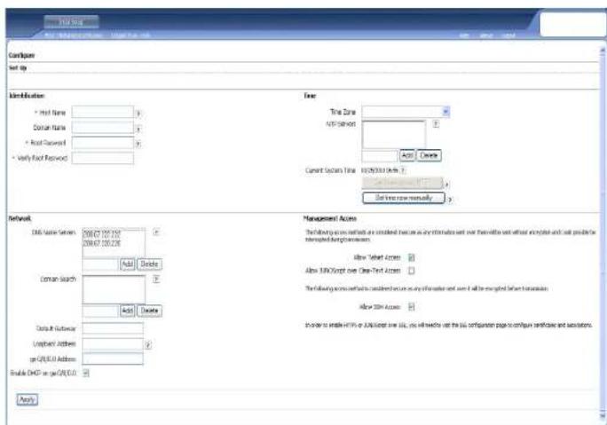
Part 8: Configure the Basic Settings
Configure the basic settings such as Host Name, Domain Name, and Root Password for your services gateway.
IMPORTANT: Ensure that you have configured the IP address and root password before you apply the configuration.
NOTE: All fields marked with an asterisk (*) are mandatory.
If you have used Method 2 in Part 6 to obtain an IP address on your services gateway, ensure that you make the following J-Web modifications:
- Unselect the Enable DHCP on ge-0/0/0.0 check box.
- Enter the manual IP address provided by your ISP in the ge-0/0/0.0 address field. The IP address must be entered in the a.b.c.d/xx format, where xx is the subnet mask.
- Enter the IP address of the gateway in the Default Gateway field. The IP address for the gateway is also provided by the ISP.
- Enter server names in the DNS name servers field. The server names will be provided by your ISP.
- Apply the configuration.
Part 9: Apply the Basic Configuration
- Click Commit to save the basic configuration.
- Click Apply to apply the basic configuration.
NOTE: To make any changes to the interface configuration, see the Branch SRX Series Services Gateways Golden Configurations at http://www.juniper.net/us/en/local/pdf/app-notes/3500153-en.pdf.
Part 10: Verify the Configuration
Access http://www.support.dell.com to ensure that you are connected to the internet. This connectivity ensures that you can pass traffic through the services gateway.
NOTE: If the http://www.support.dell.com page does not load, verify your configuration settings, and ensure that you have applied the configuration.
After you have completed these steps, you can pass traffic from any trust port to the untrust port.
Connecting and Configuring the J-SRX240 Services Gateway with Integrated Convergence Services
If you have a J-SRX240H-P-MGW model, use the instructions below to configure voice support on the media gateway and get started using your device to place and receive calls.
The following table provides an overview of the steps you must follow to configure voice support on the media gateway.
Step Task Step Task
1 Connect the FXO and FXS ports. 7 Configure the trunk.
2 Access the J-Web interface. 8 Configure trunk groups.
3 Configure the class of restriction. 9 Create the dial plan.
4 Configure the SIP station. 10 Configure the media gateway.
5 Configure the analog station. 11 Configure the survivable call server.
6 Configure the peer call server.
Part 1: Connect the FXS and FXO Ports
- Connect an FXS port (FXS1 or FXS2) on the device to an analog device such as a telephone, fax, or modem through an RJ-11 cable.
- Connect an FXO port (FXO1 or FXO2) on the device to the central office (CO) switches or to a station port on a PSTN through an RJ-11 cable.
- Connect an Ethernet cable from any of the PoE ports (ge-0/0/0 through ge-0/0/15) to the VoIP phone.
Part 2: Access the J-Web Interface
- Launch a Web browser from the management device.
- Log on using the credentials you set during the initial configuration described in the "Connecting and Configuring the J-SRX240 Services Gateway" section.
- The J-Web Dashboard page is displayed.
Part 3: Configure the Class of Restriction
Configure the class of restriction to define the policy dedicated to specifying call type permissions:
- Select Configure > Convergence Services > Station > Class of Restriction. The Class of Restriction Configuration page is displayed.
- Click Add to create a new class of restriction. The New Class of Restriction page is displayed.
- Enter the name in the Class of Restriction field.
- Click Add to add a new policy to the class of restriction you are creating. The New Policy Configuration page is displayed.
- Perform the following actions:
Field Action
| Policy Name Specify a name for the policy. |
| Available Call Types Select the call types applicable to your setup. |
| Permissions Set permissions (allow or deny) on the selected call types. |
NOTE: By default, only intra-branch calls and emergency calls are allowed.
Part 4: Configure the SIP Station
NOTE: For initial configuration of the device, you do not need to configure the station templates. You can use the default values.
- Select Configure > Convergence Services > Station. The Station Configuration page is displayed.
- Click Add to add the new station and perform the following mandatory basic actions:
Field Action
| Name Specify a name for the station. |
| Extensions Enter the extension number of the station. |
| Class of Restriction Select the already configured class of restriction. |
| Template Name Select the already defined station template. |
You can configure the analog templates to be similar so that they can share a common configuration.
Part 5: Configure the Analog Station
- Select Configure > Convergence Services > Station. The Station Configuration page is displayed.
- Click Add to add the new station and perform the following mandatory basic actions:
Field Action
| Name Specify a name for the station. | |
| Extensions Enter the extension number of the station. | |
| Class of Restriction Select the already configured class of restriction. | |
| Template Name | Select the already defined station template. |
| TDM Interface | Specify the type of TDM interface to be configured (FXO, FXS, or T1). |
NOTE: You can configure the individual SIP stations similarly so that they can share a common configuration.
Part 6: Configure the Peer Call Server
Configure the peer call server that provides call routing and call handling services for the device:
- Select Configure > Convergence Services > Call Server. The Peer Call Server Configuration page is displayed.
- Perform the following mandatory basic actions:
| Field | Action |
| Name | Specify the name for the peer call server. |
| PSTN Access Number | Specify the external PSTN number for the survivable call server to use if it must contact the PSTN directly. |
| Address Type | Select the address type as either fqdn or ipv4-address. |
| FQDN | Enter the fully qualified domain name. |
| IP Address | Enter the IP address of the peer call server. |
NOTE: When configuring the peer call server:
For the device to authenticate itself with the peer call server, you might need to provide the device user ID and password details as provided by the peer call server's administrator.
■ You can accept the default values in the Port (5060) and Transport (UDP) fields.
For initial configuration of the device, you do not need to specify the codec. The default set of codecs is used. By default, codecs are specified in the following order: 711- , G711-A, G729AB.
Part 7: Configure a Trunk
Configure a trunk for a PSTN time-division multiplexing (TDM) interface to be used by the device or the survivable call server to route calls to the destination.
-
Select Configure > Convergence Services > Gateway > Trunks. The New Trunk Configuration page is displayed.
-
Perform the following actions:
Field Action
Trunk Name Enter a name for the trunk.
Trunk Type Select the trunk type (FXO, FXS, or T1).
TDM Interface Select the type of TDM interface to be configured (FXO, FXS, or T1) for routing certain types of calls.
Part 8: Configure the Trunk Groups
A trunk group comprises multiple trunks specified in the order of precedence in which they must be selected to route a call.
-
Select Configure > Convergence Services > Gateway > Trunk Groups. The Trunk Group Configuration page is displayed.
-
Click Add to create a new trunk group and perform the following mandatory actions:
Field Action
Name Specify a name for the trunk group.
Available Trunks Select the trunks applicable to your setup.
Part 9: Create the Dial Plan
Create the dial plan to enable the peer call server to route outbound calls placed from SIP telephones/analog stations at the branch to its PSTN:
- Select Configure > Convergence Services > Dial Plan and click on Dial Plan. The Dial Plan Configuration page is displayed.
-
Click Add to create a new dial plan. The New Dial Plan Configuration page is displayed.
-
Enter a name in the Dial Plan Name field and click Add. The New Route Pattern Configuration page displays.
- Perform the following mandatory basic actions:
Field Action
Route Pattern Specify the route pattern name.
Call Type Select the call type. The default is trunk-call.
Trunk-groups Select the preconfigured trunk groups to include in the route pattern.
NOTE: You can accept the default values for the Preference and Digit Manipulation fields.
Part 10: Configure the Media Gateway
Configure the media gateway to enable users to place calls within the branch and externally when the peer call server is accessible to provide call routing and other call handling services:
- Select Configure > Convergence Services > Media Gateway > Gateway. The Media Gateway Configuration page is displayed.
- Click Add and enter the following mandatory settings:
Field Action
Media Gateway Specify the device name.
Call Server Select a peer call with which to associate.
Dial Plan Select a preconfigured dial plan.
Zone Specify the service point for the device's zone to enable the media gateway and survivable call server services for the specified zone.
NOTE: You can accept the default values in the Port (5060) and Transport (UDP) fields.
Part 11: Configure the Survivable Call Server
This server assumes the responsibilities of the peer call server when the peer call server is unreachable:
- Select Configure > Convergence Services > Call Service. The Survivable Call Service page is displayed.
- Click Add to create a new call service and perform the following mandatory basic actions:
Field Action
Call Service Name Specify the name for the call service.
Call Server Select the peer call server name.
Dial Plan Select the preconfigured dial plan to be used for the survivable call server.
Zone Specify the name for the zone.
NOTE: All other parameters required to configure the call service are optional and you can accept the default values set for these parameters.
Powering Off the Device
You can power off the device in one of the following ways:
■ Graceful shutdown—Press and immediately release the Power button. The device begins gracefully shutting down the operating system.
■ Immediate shutdown—Press the Power button and hold it for 10 seconds. The device immediately shuts down. Press the Power button again to power on the device.
NOTE: You can reboot or halt the system in the J-Web interface by selecting Maintain > Reboot.
For additional configuration information, see the Branch SRX Series Services Gateways Golden Configurations at http://www.juniper.net/us/en/local/pdf/app-notes/3500153-en.pdf.
For detailed software configuration information, see the software documentation available at http://www.juniper.net/techpubs/software/junos-srx/index.html.
Contacting Dell
For technical support, see http://www.support.dell.com.
Information in this document is subject to change without notice. All rights reserved. Reproduction of these materials in any manner whatsoever without the written permission of Juniper Networks is strictly forbidden. Trademarks used in this text: Dell™, the DELL™ logo, and PowerConnect™ are trademarks of Dell Inc. Juniper Networks® and G33® are registered trademarks of Juniper Networks, Inc. in the United States and other countries. All other trademarks, service marks, registered trademarks, or registered service marks are the property of their respective owners. Juniper Networks assumes no responsibility for any inaccuracies in this document. Juniper Networks reserves the right to change, modify, transfer, or otherwise revise this publication without notice. Products made or sold by Juniper Networks or components thereof might be covered by one or more of the following patents that are owned by or licensed to Juniper Networks: U.S. Patent Nos. 5,473,599, 5,905,725, 5,909,440, 6,192,051, 6,333,650, 6,359,479, 6,406,312, 6,429,706, 6,459,579, 6,493,347, 6,538,518, 6,538,899, 6,552,918, 6,567,902, 6,578,186, and 6,590,785. Copyright © 2010, Juniper Networks, Inc. All rights reserved. Printed in USA. Part Number: 530-036274 REV 01, July 2010.

第8部分:進行基本設定
第8部分:配置基本设置
http://www.juniper.net/us/en/local/pdf/app-notes/3500153-en.pdf.
第10部分:验证配置
http://www.juniper.net/us/en/local/pdf/app-notes/3500153-en.pdf.
有关软件配置的详细信息,请参阅
Angka Keterangan
Angka Keterangan
| 1 Porta suara FXS |
| 2 Porta suara FXO |
| 3 Unit catu daya |
| 4 Titik pentanahan |
Model J-SRX240 Services Gateway
Tersedia empat model J-SRX240 Services Gateway berikut ini:
PENGATURAN DEFAULT PABRIK UNTUK POLICY KEAMANAN
| Zona Sumber | Zona Tujuan | Tindakan Policy |
| trust | untrust | izinkan |
| trust | trust | izinkan |
| untrust | trust | tolak |
PENGATURAN DEFAULT PABRIK UNTUK ATURAN NAT
| Zona Sumber | Zona Tujuan | Tindakan Policy |
| trust | untrust | Antamuka NAT sumber ke zona untrust |
Bagian 8: Mengonfigurasi Pengaturan Dasar
http://www.juniper.net/us/en/local/pdf/app-notes/3500153-en.pdf.
パート8: 基本設定を構成
J-SRX240 Services Gateway (J-SRX240B, J-SRX240H) 전면 패널
J-SRX240 Services Gateway (J-SRX240B, J-SRX240H, J-SRX240H-POE) 후 면 패널
8부:기본설정 구성
Legenda Descrição
1 Porta de voz FXS
2 Porta de voz FXO
http://www.juniper.net/us/en/local/pdf/app-notes/3500153-en.pdf.
Leyenda Descripción
http://www.juniper.net/us/en/local/pdf/app-notes/3500153-en.pdf.
http://www.juniper.net/us/en/local/pdf/app-notes/3500153-en.pdf.
No Açıklama
Dell PowerConnect J-Series J-SRX240
J-SRX240 Services Gateway Hardware Guide-コツ" ,コツ" ,コツ" Services Gateway
הכלה
⑤
| 1Mini-PIM 5qion n## | |||||
| (0/15 tv 0/0) Gigabit Ethernet | 6 | (n#v#n) Power p#n? | 2 | ||
| 7USB n## | 3 . (n##n) ALARM LED n## | 1Mini-PIM n | |||
| STATUS , (n#v#n) POWER, mPIM , HA , (o#v#o) EXPCARD | (0/15 tv 0/0) Gigabit Ethernet | 6 (n#v#n) Power p#n? | 2 | ||
| 7USB n## | 3 , (n##n) # | ||||
| 4 o#w) Reset Config p#n? | STATUS , (n#v#n) POWER, mPIM , HA , (o#v#o) EXPCARD | ||||
| ### | |
| FXS ### | 1 |
| FXO ### | 2 |
| ### | 3 |
| ### | 4 |
.הכלהה/הכלהה-הכלהה-הכלהה-הכלהה-הכלהה-הכלהה-הכלהה-הכלהה-הכלהה-הכלהה-הכלהה-הכלהה-הכלהה-הכלהה-הכלהה-הכלהה-הכלהה-הכלהה-הכלה
.הכלההוּרָהוּרָהוּרָהוּרָהוּרָהוּרָהוּרָהוּרָהוּרָהוּרָהוּרָהוּרָהוּרָהוּרָהוּרָה: (הכלה) (הכלה) POWER
New Class of Restriction , , , , , , , , , ( ) Add , 2
.(שַׁה בְרָה אַעֹם)
.(הכלההוּרָה) New Policy Configuration
(תָׁרְהָרִיָה) Station Configuration (תָׁרְהָרִיָה). (תָׁרְהָרִיָה) Station
הכלההוּרָהוּרָהוּרָהוּרָהוּרָהוּרָהוּרָהוּרָהוּרָהוּרָהוּרָהוּרָהוּרָהוּרָהוּרָה:9,770
Commit 1.
Branch SRX Series Services Gateways Golden Configurations-1
.http://www.juniper.net/us/en/local/pdf/app-notes/3500153-en.pdf
הכלההוּרָהוּרָהוּרָהוּרָהוּרָהוּרָהוּרָהוּרָהוּרָהוּרָהוּרָהוּרָהוּרָהוּרָהוּרָה:10 וַת
untrust isv'st trust isv'st, isv'st, isv'st
Dial Plan Configuration (בַרְהָרִי) Dial Plan (בַרְהָרִי), (בַרְהָרִי).
New Dial Plan Configuration ( \eta_{1} ) , ( \eta_{2} ) , ( \eta_{3} ) , ( \eta_{4} ) , ( \eta_{5} ) , ( \eta_{6} ) , ( \eta_{7} ) , ( \eta_{8} ) , ( \eta_{9} ) , ( \eta_{10} ) , ( \eta_{11} ) , ( \eta_{12} ) , ( \eta_{13} ) , ( \eta_{14} ) , ( \eta_{15} ) , ( \eta_{16} ) , ( \eta_{17} ) , ( \eta_{18} ) , ( \eta_{19} ) , ( \eta_{20} ) , ( \eta_{21} ) , ( \eta_{22} ) , ( \eta_{23} ) , ( \eta_{24} ) , ( \eta_{25} ) , ( \eta_{26} ) , ( \eta_{27} ) , ( \eta_{28} ) , ( \eta_{29} ) , ( \eta_{30} ) , ( \eta_{31} ) , ( \eta_{32} ) , ( \eta_{33} ) , ( \eta_{34} ) , ( \eta_{35} ) , ( \eta_{36} ) , ( \eta_{37} ) , ( \eta_{38} ) , ( \eta_{39} ) , ( \eta_{40} ) , ( \eta_{41} ) , ( \eta_{42} ) , ( \eta_{43} ) , ( \eta_{44} ) , ( \eta_{45} ) , ( \eta_{46} ) , ( \eta_{47} ) , ( \eta_{48} ) , ( \eta_{49} ) , ( \eta_{50} ) , ( \eta_{51} ) , ( \eta_{52} ) , ( \eta_{53} ) , ( \eta_{54} ) , ( \eta_{55} ) , ( \eta_{56} ) , ( \eta_{57} ) , ( \eta_{58} ) , ( \eta_{59} ) , ( \eta_{60} ) , ( \eta_{61} ) , ( \eta_{62} ) , ( \eta_{63} ) , ( \eta_{64} ) , ( \eta_{65} ) , ( \eta_{66} ) , ( \eta_{67} ) , ( \eta_{68} ) , ( \eta_{69} ) , ( \eta_{70} ) , ( \eta_{71} ) , ( \eta_{72} ) , ( \eta_{73} ) , ( \eta_{74} ) , ( \eta_{75} ) , ( \eta_{76} ) , ( \eta_{77} ) , ( \eta_{78} ) , ( \eta_{79} ) , ( \eta_{80} ) , ( \eta_{81} ) , ( \eta_{82} ) , ( \eta_{83} ) , ( \eta_{84} ) , ( \eta_{85} ) , ( \eta_{86} ) , ( \eta_{87} ) , ( \eta_{88} ) , ( \eta_{89} ) , ( \eta_{90} ) , ( \eta_{91} ) , ( \eta_{92} ) , ( \eta_{93} ) , ( \eta_{94} ) , ( \eta_{95} ) , ( \eta_{96} ) , ( \eta_{97} ) , ( \eta_{98} ) , ( \eta_{99} ) , ( .2
(בַרְהָרִיָה לַרְהָרִיָה)
| הכלה | |
| (ow) Name. | |
| (nin) Extensions. | |
| (nin) Class of Restriction. | |
| (nin) Template Name. | |
| (T1 ix ,FXS ,FXO) TDM Window 2000 (TDM Window) TDM Interface | |
| (SIP Window) SIP Window 2000 (SIP Window) SIP Window 2000 (SIP Window) SIP Window 2000 (SIP Window) SIP Window 2000 (SIP Window) SIP Window 2000 (SIP Window) SIP Window 2000 (SIP Window) SIP Window 2000 (SIP Window) SIP Window 2000 (SIP Window) SIP Window 2000 (SIP Window) |
. Transport (UDP) - Port (5060)


- Dell PowerConnect J-Series J-SRX240 Services Gateway Quick Start
- J-SRX240 Services Gateway Models
- Connecting and Configuring the J-SRX240 Services Gateway
- Part 1: Connect the Services Gateway to Earth Ground
- Part 2: Connect the Power Cable to the Device
- Part 3: Connect the Management Device
- Part 4: Understand the Default Configuration Settings
- Part 5: Ensure that the Management Device Acquires an IP Address
- Part 6: Ensure that an IP Address is Assigned to the Services Gateway
- METHOD 1: OBTAINING A DYNAMIC IP ADDRESS ON YOUR SERVICES GATEWAY
- METHOD 2: OBTAINING A STATIC IP ADDRESS ON YOUR SERVICES GATEWAY
- Part 7: Access the J-Web Interface
- Part 8: Configure the Basic Settings
- Part 9: Apply the Basic Configuration
- Part 10: Verify the Configuration
- Connecting and Configuring the J-SRX240 Services Gateway with Integrated Convergence Services
- Step Task Step Task
- Part 1: Connect the FXS and FXO Ports
- Part 2: Access the J-Web Interface
- Part 3: Configure the Class of Restriction
- Part 4: Configure the SIP Station
- Part 5: Configure the Analog Station
- Part 6: Configure the Peer Call Server
- Part 7: Configure a Trunk
- Field Action
- Part 8: Configure the Trunk Groups
- Part 9: Create the Dial Plan
- Part 10: Configure the Media Gateway
- Part 11: Configure the Survivable Call Server
- Powering Off the Device
- Contacting Dell
- 第8部分:進行基本設定
- 第8部分:配置基本设置
- 第10部分:验证配置
- Model J-SRX240 Services Gateway
- Bagian 8: Mengonfigurasi Pengaturan Dasar
- パート8: 基本設定を構成
- 8부:기본설정 구성
- Legenda Descrição
- No Açıklama
- הכלההוּרָהוּרָהוּרָהוּרָהוּרָהוּרָהוּרָהוּרָהוּרָהוּרָהוּרָהוּרָהוּרָהוּרָהוּרָה:9,770
- הכלההוּרָהוּרָהוּרָהוּרָהוּרָהוּרָהוּרָהוּרָהוּרָהוּרָהוּרָהוּרָהוּרָהוּרָהוּרָה:10 וַת
Brand : DELL
Model : PowerConnect JSRX240
Category : Network Equipment