
Force10 S50-01-GE-48T-V - Uncategorized DELL - Free user manual and instructions
Find the device manual for free Force10 S50-01-GE-48T-V DELL in PDF.


| Product Type | Managed Gigabit Ethernet Switch with PoE |
| Model | Force10 S50-01-GE-48T-V |
| Dimensions | Approximately 44.2 x 38.1 x 4.4 cm (1U rackmount) |
| Weight | Approximately 7.5 kg |
| Power Supply | AC 100-240V, 50-60Hz; supports PoE (max 370W PoE budget) |
| Ports | 48 x 10/100/1000BASE-T (PoE) + 4 x 10 Gigabit SFP+ uplinks |
| Switching Capacity | Up to 176 Gbps |
| Operating System | FTOS (Force10 Operating System) with CLI support |
| Layer 2 Features | VLAN, STP, RSTP, MSTP, PVST+, GVRP, Link Aggregation (LACP) |
| Layer 3 Features | Static routing, OSPF, IS-IS, RIP, BGP, VRRP, Policy-based Routing |
| Quality of Service | 802.1p, DSCP, Traffic shaping, Policing, Queuing |
| Security | ACLs, 802.1X port authentication, SSH, TACACS+, RADIUS, DHCP snooping |
| Management | CLI, SNMP v1/v2/v3, RMON, Syslog, Web GUI (if enabled) |
| PoE Standard | IEEE 802.3af/at (PoE/PoE+) |
| Stacking | Physical stacking up to 12 units (S-Series stacking) |
| Cooling | Internal fans with temperature-controlled speed |
| Operating Temperature | 0°C to 45°C (32°F to 113°F) |
| Storage Temperature | -20°C to 70°C (-4°F to 158°F) |
| Humidity | 10% to 90% non-condensing |
| Maintenance | Clean with a dry, soft cloth. Do not use liquid cleaners. Ensure proper ventilation. |
| Safety | Use grounded power outlets. Do not open the chassis. Follow electrostatic discharge precautions. |
| Spare Parts & Repairability | Hot-swappable power supplies and fans; field-replaceable SFP modules. Contact Dell support. |
Frequently Asked Questions - Force10 S50-01-GE-48T-V DELL
User questions about Force10 S50-01-GE-48T-V DELL
0 question about this device. Answer the ones you know or ask your own.
Ask a new question about this device
Download the instructions for your Uncategorized in PDF format for free! Find your manual Force10 S50-01-GE-48T-V - DELL and take your electronic device back in hand. On this page are published all the documents necessary for the use of your device. Force10 S50-01-GE-48T-V by DELL.
USER MANUAL Force10 S50-01-GE-48T-V DELL
Notes, Cautions, and Warnings
NOTE: A NOTE indicates important information that helps you make better use of your computer.
CAUTION: A CAUTION indicates potential damage to hardware or loss of data if instructions are not followed.
WARNING: A WARNING indicates a potential for property damage, personal injury, or death.
Information in this publication is subject to change without notice. © 2012 Dell Force10. All rights reserved.
Reproduction of these materials in any manner whatsoever without the written permission of Dell Inc. is strictly forbidden.
Trademarks used in this text: Dell™, the DELL logo, Dell Precision™, OptiPlex™, Latitude™, PowerEdge™, PowerVault™, PowerConnect™, OpenManage™, EqualLogic™, KACETM, FlexAddress™ and Vostro™ are trademarks of Dell Inc. Intel®, Pentium®, Xeon®, Core™ and Celeron® are registered trademarks of Intel Corporation in the U.S. and other countries. AMD® is a registered trademark and AMD Opteron™, AMD Phenom™, and AMD Sempron™ are trademarks of Advanced Micro Devices, Inc. Microsoft®, Windows®, Windows Server®, MS-DOS® and Windows Vista® are either trademarks or registered trademarks of Microsoft Corporation in the United States and/or other countries. Red Hat Enterprise Linux® and Enterprise Linux® are registered trademarks of Red Hat, Inc. in the United States and/or other countries. Novell® is a registered trademark and SUSE™ is a trademark of Novell Inc. in the United States and other countries. Oracle® is a registered trademark of Oracle Corporation and/or its affiliates. Citrix®, Xen®, XenServer® and XenMotion® are either registered trademarks or trademarks of Citrix Systems, Inc. in the United States and/or other countries. VMware®, Virtual SMP®, vMotion®, vCenter®, and vSphere® are registered trademarks or trademarks of VMWare, Inc. in the United States or other countries.
Other trademarks and trade names may be used in this publication to refer to either the entities claiming the marks and names or their products. Dell Inc. disclaims any proprietary interest in trademarks and trade names other than its own.
Table of Contents
1 Preface
Objectives 13
Audience 13
Conventions 13
Information Symbols 14
Related Documents 14
2 CLI Basics
Accessing the Command Line ....15
Multiple Configuration Users 16
Navigating the Command Line Interface 16
Obtaining Help 17
Using the Keyword No 19
Filtering show Commands 19
Displaying All Output 20
Filtering Command Output Multiple Times .....20
Command Modes 20
EXEC Mode 21
EXEC Privilege Mode ....21
CONFIGURATION Mode 21
INTERFACE Mode ....21
LINE Mode 22
TRACE-LIST Mode 22
MAC ACCESS LIST Mode .....22
IP ACCESS LIST Mode ....23
ROUTE-MAP Mode .....23
PREFIX-LIST Mode .....23
AS-PATH ACL Mode .....23
IP COMMUNITY LIST Mode .....24
REDIRECT-LIST Mode 24
SPANNING TREE Mode 24
Per-VLAN SPANNING TREE Plus Mode .....24
RAPID SPANNING TREE Mode 25
MULTIPLE SPANNING TREE Mode .....25
PROTOCOL GVRP Mode .....25
ROUTER OSPF Mode 25
ROUTER RIP Mode ....26
ROUTER ISIS Mode 26
ROUTER BGP Mode 26
Determining the Chassis Mode 26
3 File Management
Overview 27
Basic File Management Commands 27
Upgrading the C-Series FPGA 56
4 BOOT\_USER Mode
Overview 59
Commands 59
5 Control and Monitoring
Overview 73
Commands 73
6 802.1ag
Overview 159
Commands 159
7 802.3ah
Overview 171
Commands 171
8 802.1X
Important Points to Remember 183
9 Access Control Lists (ACL)
Overview 199
Commands Common to all ACL Types 199
Common IP ACL Commands 201
Standard IP ACL Commands 205
Extended IP ACL Commands .....212
Common MAC Access List Commands .243
Standard MAC ACL Commands .....246
Extended MAC ACL Commands .251
IP Prefix List Commands .....256
Route Map Commands .....262
AS-Path Commands 279
IP Community List Commands .....282
10 ACL VLAN Group
Overview 287
Commands 287
11 Bidirectional Forwarding Detection (BFD)
Overview 293
Commands 293
12 Border Gateway Protocol IPv4 (BGPv4)
Overview 307
BGPv4 Commands 307
MBGP Commands 383
BGP Extended Communities (RFC 4360)....410
13 Content Addressable Memory (CAM) for ExaScale
Overview 419
Commands 419
Important Points to Remember 420
14 Content Addressable Memory (CAM)
Overview 427
CAM Profile Commands 427
Important Points to Remember ....428
CAM IPv4flow Commands 439
CAM Layer 2 ACL Commands ....442
15 Configuration Rollback
Overview 445
Commands 445
16 Dynamic Host Configuration Protocol (DHCP)
Overview 455
Commands to Configure the System to be a DHCP Server .....455
Commands to Configure Secure DHCP 463
17 Equal Cost Multi-Path
Overview 471
Commands 471
18 Far-End Failure Detection (FEFD)
Overview 477
Commands 477
19 Force10 Resilient Ring Protocol (FRRP)
Overview 483
Commands 483
Important Points to Remember ....483
20 Force10 Service Agent
Overview 491
Commands 491
21 GARP VLAN Registration (GVRP)
Overview 523
Commands 523
Important Points to Remember 524
22 High Availability (HA)
Overview 533
Commands 533
23 Internet Group Management Protocol (IGMP)
Overview 543
IGMP Commands 543
Important Points to Remember .....543
IGMP Snooping Commands ....553
Important Points to Remember for IGMP Snooping .....553
Important Points to Remember for IGMP Querier ....554
24 Interfaces
Overview 559
Basic Interface Commands ....559
Port Channel Commands 614
Time Domain Reflectometer (TDR) 624
Important Points to Remember 624
UDP Broadcast 625
Important Points to Remember 626
25 IPv4 Routing
Overview 629
Commands 629
26 IPv6 Access Control Lists (IPv6 ACLs)
Overview 681
Important Points to Remember 681
IPv6 ACL Commands 682
IPv6 Route Map Commands 708
27 IPv6 Basics
Overview 713
Commands 713
28 IPv6 Border Gateway Protocol (IPv6 BGP)
Overview 731
IPv6 BGP Commands 731
IPv6 MBGP Commands 793
29 Intermediate System to Intermediate System (IS-IS)
Overview 817
Commands 817
30 Link Aggregation Control Protocol (LACP)
Overview 859
Commands 859
31 Layer 2
Overview 865
MAC Addressing Commands 865
Virtual LAN (VLAN) Commands .884
32 Link Layer Detection Protocol (LLDP)
Overview 893
Commands 893
LLDP-MED Commands .902
33 Multicast Listener Discovery (MLD)
Overview 911
MLD Commands 911
MLD Snooping Commands 918
34 Multicast Source Discovery Protocol (MSDP)
Overview 923
Commands 923
35 Multiple Spanning Tree Protocol (MSTP)
Overview 933
Commands 933
36 Multicast
Overview 949
IPv4 Multicast Commands .....949
IPv6 Multicast Commands .....966
37 Neighbor Discovery Protocol (NDP)
Overview 973
Commands 973
38 Object Tracking
Overview 981
IPv4 Object Tracking Commands 981
IPv6 Object Tracking Commands 995
39 Open Shortest Path First (OSPFv2 and OSPFv3)
Overview 1001
OSPFv2 Commands 1001
OSPFv3 Commands 1059
40 Policy-based Routing (PBR)
Overview 1081
Commands 1081
41 PIM-Dense Mode (PIM-DM)
Overview 1091
IPv4 PIM-Dense Mode Commands .....1091
42 PIM-Sparse Mode (PIM-SM)
Overview 1093
IPv4 PIM-Sparse Mode Commands .....1093
IPv6 PIM-Sparse Mode Commands 1116
43 PIM-Source Specific Mode (PIM-SSM)
Overview 1127
IPv4 PIM Commands 1127
IPv4 PIM-Source Specific Mode Commands 1127
IPv6 PIM Commands 1129
IPv6 PIM-Source Specific Mode Commands 1129
44 Power over Ethernet (PoE)
Overview 1131
Commands 1131
45 Port Monitoring
Overview 1137
Commands 1137
Important Points to Remember 1138
46 Private VLAN (PVLAN)
Overview 1151
Commands 1151
Private VLAN Concepts 1151
47 Per-VLAN Spanning Tree plus (PVST+)
Overview 1161
Commands 1161
48 Quality of Service (QoS)
Overview 1175
Global Configuration Commands 1175
Per-Port QoS Commands 1176
Policy-Based QoS Commands 1184
Important Points to Remember—multicast-bandwidth option .....1197
Queue-Level Debugging 1220
49 Router Information Protocol (RIP)
Overview 1231
Commands 1231
50 Remote Monitoring (RMON)
Overview 1249
Commands 1249
51 Rapid Spanning Tree Protocol (RSTP)
Overview 1261
Commands 1261
52 Security
Overview 1273
Commands 1273
AAA Accounting Commands 1273
Authorization and Privilege Commands 1276
Authentication and Password Commands ....1280
RADIUS Commands 1291
TACACS+ Commands 1296
Port Authentication (802.1X) Commands 1299
Important Points to Remember 1299
SSH Server and SCP Commands 1306
Trace List Commands 1318
Secure DHCP Commands 1328
53 Service Provider Bridging
Overview 1333
Commands 1333
Important Points to Remember 1333
54 sFlow
Overview 1339
Important Points to Remember 1339
Commands 1340
55 SNMP and Syslog
Overview 1351
SNMP Commands 1351
Important Points to Remember 1352
Syslog Commands 1367
56 SONET
Overview 1379
Commands 1379
57 S-Series Stacking Commands
Overview 1397
Commands 1397
58 Storm Control
Overview 1405
Commands 1405
Important Points to Remember 1405
59 Spanning Tree Protocol (STP)
Overview 1413
Commands 1413
60 Time and Network Time Protocol (NTP)
Overview 1425
Commands 1425
61 Uplink Failure Detection (UFD)
Overview 1441
Commands 1441
62 VLAN Stacking
Overview 1451
Commands 1451
Important Points to Remember 1451
63 Virtual Routing and Forwarding (VRF)
Overview 1461
Commands 1461
64 Virtual Router Redundancy Protocol (VRRP)
Overview 1471
IPv4 VRRP Commands....1471
IPv6 VRRP Commands ....1485
65 C-Series Diagnostics and Debugging
Overview 1491
Inter-process Communication Commands 1491
RPM Management Port Commands 1497
Data Path Debugging Commands 1499
Interface Troubleshooting Commands 1502
Advanced ASIC Debugging Commands 1506
ACL and System-Flow Debug Commands 1510
Interface Management Debug Commands ....1512
Layer 2 Debug Command ....1514
Trace Logging Commands 1515
Offline Diagnostic Commands 1521
PoE Hardware Status Commands....1523
Buffer Tuning Commands 1524
66 E-Series ExaScale Debugging and Diagnostics
Overview 1531
Diagnostics and Monitoring Commands 1531
Important Points to Remember 1532
Offline Diagnostic Commands 1549
Hardware Commands 1552
67 E-Series Debugging and Diagnostics
Overview 1575
Diagnostics and Monitoring Commands ....1575
Important Points to Remember 1576
Offline Diagnostic Commands 1596
Hardware Commands 1598
68 S-Series Debugging and Diagnostics
Offline Diagnostic Commands 1615
Important Points to Remember 1615
Buffer Tuning Commands 1617
Hardware Commands 1622
A ICMP Message Types
B SNMP Traps
Index
Command Index
Preface
About this Guide
This book provides information on the FTOS Command Line Interface (CLI). It includes some information on the protocols and features found in FTOS and on the Dell Force10 systems supported by FTOS (C-Series C, E-Series E, and S-Series S).
This chapter includes:
- Objectives
- Audience
- Conventions
- Related Documents
Objectives
This document is intended as a reference guide for the FTOS command line interface (CLI) commands, with detailed syntax statements, along with usage information and sample output.
For details on when to use the commands, refer to the FTOS Configuration Guide. That guide contains an Appendix with a list of the RFCs and MIBs (management information base files) supported.
Audience
This document is intended for system administrators who are responsible for configuring or maintaining networks. This guide assumes you are knowledgeable in Layer 2 and Layer 3 networking technologies.
Conventions
This document uses the following conventions to describe command syntax:
Convention Description
| keyword | Keywords are in bold and should be entered in the CLI as listed. |
| parameter | Parameters are in italics and require a number or word to be entered in the CLI. |
| {X} Keywords and parameters within braces must be entered in the CLI. |
| [X] Keywords and parameters within brackets are optional. |
| x | y Keywords and parameters separated by bar require you to choose one. |
| x||y Keywords and parameters separated by a double bar enables you to choose any or all of them. |
Information Symbols
Table 1-1 describes symbols contained in this guide.
Table 1-1. Information Symbols
| Symbol Brief | Description | |
| [4W8A] | Note | This symbol signals important operational information. |
| [KDYB] | Caution | This symbol signals information about situations that could result in equipment damage or loss of data. |
 | Warning | This symbol signals information about hardware handling that could result in injury. |
| [HYZ] | C-Series | This symbol indicates that the selected feature is supported on the C-Series. |
| [SYB] | E-Series | This symbol indicates that the selected feature is supported on the E-Series TeraScale AND E-Series ExaScale. |
 | E-Series TeraScale | This symbol indicates that the selected feature is supported on the E-Series TeraScale platform only. |
| [STCC] | E-Series ExaScale | This symbol indicates that the selected feature is supported on the E-Series ExaScale platform only. |
| [S] | S-Series | This symbol indicates that the selected feature is supported on the S-Series. |
Related Documents
For more information about the system, refer to the following documents:
- FTOS Configuration Guide
• Installation and maintenance guides for your system - Release Notes for your system and FTOS version
CLI Basics
This chapter describes the command structure and command modes. FTOS commands are in a text-based interface that allows you to use launch commands, change the command modes, and configure interfaces and protocols.
This chapter covers the following topics:
- Accessing the Command Line
• Multiple Configuration Users - Navigating the Command Line Interface
- Obtaining Help
• Using the Keyword No
• Filtering show Commands - Command Modes
Accessing the Command Line
When the system boots successfully, you are positioned on the command line in the EXEC mode and not prompted to log in. You can access the commands through a serial console port or a Telnet session. When you Telnet into the switch, you are prompted to enter a login name and password.
Figure 2-1 is an example of a successful Telnet login session.
Figure 2-1. Login Example
telnet 172.31.1.53
Trying 172.31.1.53...
Connected to 172.31.1.53.
Escape character is '^]'.
Login: username
Password:
Force10>
Once you log into the switch, the prompt provides you with current command-level information (refer to Table 2-1).
Multiple Configuration Users
When a user enters the CONFIGURATION mode and another user(s) is already in that configuration mode, FTOS generates an alert warning message similar to the following:
Figure 2-2. Configuration Mode User Alert
Force10#conf
% Warning: The following users are currently configuring the system:
User "" on line console0
User "admin" on line vty0 (123.12.1.123)
User "admin" on line vty1 (123.12.1.123)
User "Irene" on line vty3 (123.12.1.321)
Force10(conf)#Force10#
When another user enters the CONFIGURATION mode, FTOS sends a message similar to the following, where the user in this case is “admin” on vty2:
% Warning: User "admin" on line vty2 "172.16.1.210" is in configuration
Navigating the Command Line Interface
The Command Line Interface (CLI) prompt displayed by FTOS is comprised of:
- “hostname”— the initial part of the prompt, “Force10” by default. You can change it with the hostname command, as described in hostname.
• The second part of the prompt, reflecting the current CLI mode, as shown in Table 2-1.
The CLI prompt changes as you move up and down the levels of the command structure. Table 2-1 lists the prompts and their corresponding command levels, called modes. Starting with the CONFIGURATION mode, the command prompt adds modifiers to further identify the mode. The command modes are explained in Command Modes.

Note: Some of the following modes are not available on C-Series or S-Series.
Table 2-1. Command Prompt and Corresponding Command Mode
| Prompt CLI Command Mode | |
| Force10> EXEC | |
| Force10# EXEC Privilege | |
| Force10(conf)# CONFIGURATION |
Table 2-1. Command Prompt and Corresponding Command Mode
| Prompt | CLI Command Mode |
| Force10(conf-if)#Force10(conf-if-gi-0/0)#Force10(conf-if-tc-0/0)#Force10(conf-if-lo-0)#Force10(conf-if-nu-0)#Force10(conf-if-po-0)#Force10(conf-if-vl-0)#Force10(conf-if-so-0/0)#Force10(conf-if-ma-0/0)#Force10(conf-if-range)# | INTERFACE |
| Force10(config-ext-nacl)#Force10(config-std-nacl)# | IP ACCESS LIST |
| Force10(config-line-aux)#Force10(config-line-console)#Force10(config-line-vty)# | LINE |
| Force10(config-ext-macl)#Force10(config-std-macl)# | MAC ACCESS LIST |
| Force10(config-mon-sess)# MONITOR SESSION | |
| Force10(config-span)# STP | |
| Force10(config-mstp)# MULTIPLE SPANNING TREE | |
| Force10(config-pvst)# Per-VLAN SPANNING TREE Plus | |
| Force10(config-rstp)# RAPID SPANNING TREE | |
| Force10(config-gvrp)# PROTOCOL GVRP | |
| Force10(config-route-map)# ROUTE-MAP | |
| Force10(conf-nprefixl)# PREFIX-LIST | |
| Force10(conf-router_rip)# ROUTER RIP | |
| Force10(conf-redirect-list)# REDIRECT | |
| Force10(conf-router_bgp)# ROUTER BGP | |
| Force10(conf-router_ospf)# ROUTER OSPF | |
| Force10(conf-router_isis)# | ROUTER ISIS |
| Force10(conf-trace-acl)# | TRACE-LIST |
Obtaining Help
As soon as you are in a command mode there are several ways to access help.
• To obtain a list of keywords at any command mode, do the following:
— Enter a ? at the prompt or after a keyword. There must always be a space before the ?.
• To obtain a list of keywords with a brief functional description, do the following:
— Enter help at the prompt.
• To obtain a list of available options, do the following:
— Type a keyword followed by a space and a ?
- Type a partial keyword followed by a ?
— A display of keywords beginning with the partial keyword is listed.
Figure 2-3 illustrates the results of entering ip ? at the prompt.
Figure 2-3. Partial Keyword Example
| Force10 (conf) #ip ? | |
| access-list | Named access-list |
| as-path | BGP autonomous system path filter |
| community-list | Add a community list entry |
| domain-list | Domain name to complete unqualified host name |
| domain-lookup | Enable IP Domain Name System hostname translation |
| domain-name | Define the default domain name |
| fib | FIB configuration commands |
| ftp | FTP configuration commands |
| host | Add an entry to the ip hostname table |
| max-frag-count | Max. fragmented packets allowed in IP re-assembly |
| multicast-routing | Enable IP multicast forwarding |
| name-server | Specify address of name server to use |
| pim | Protocol Independent Multicast |
| prefix-list | Build a prefix list |
| radius | Interface configuration for RADIUS |
| redirect-list | Named redirect-list |
| route | Establish static routes |
| scp | SCP configuration commands |
| source-route | Process packets with source routing header options |
| ssh | SSH configuration commands |
| tacacs | Interface configuration for TACACS+ |
| telnet | Specify telnet options |
| tftp | TFTP configuration commands |
| trace-group | Named trace-list |
| trace-list | Named trace-list |
| Force10 (conf) #ip | |
When entering commands, you can take advantage of the following timesaving features:
- The commands are not case sensitive.
- You can enter partial (truncated) command keywords. For example, you can enter int gig int interface for the interface gigabitethernet interface command.
- Use the TAB key to complete keywords in commands.
- Use the up arrow key to display the last enabled command.
• Use either the Backspace key or the Delete key to erase the previous character.
Use the left and right arrow keys to navigate left or right in the FTOS command line. Table 2-2 defines the key combinations valid at the FTOS command line.
Table 2-2. Short-cut Keys and their Actions
| Key Combination Action | |
| CNTL-A Moves the cursor to the beginning of the command line. | |
| CNTL-B Moves the cursor back one character. | |
| CNTL-D Deletes character at cursor. | |
| CNTL-E Moves the cursor to the end of the line. | |
| CNTL-F Moves the cursor forward one character. | |
| CNTL-I Completes a keyword. | |
| CNTL-K Deletes all characters from the cursor to the end of the command line. | |
| CNTL-L Re-enters the previous command. | |
| CNTL-N Return to more recent commands in the history buffer after recalling commands with Ctrl-P or the up arrow key | |
| CNTL-P Recalls commands, beginning with the last command | |
| CNTL-R Re-enters the previous command. | |
| CNTL-U Deletes the line. | |
| CNTL-W Deletes the previous word. | |
| CNTL-X Deletes the line. | |
| CNTL-Z Ends continuous scrolling of command outputs. | |
| Esc B Moves the cursor back one word. | |
| Esc F Moves the cursor forward one word. | |
| Esc D | Deletes all characters from the cursor to the end of the word. |
Using the Keyword No
To disable, delete, or return to default values, use the no form of the commands. For most commands, if you type the keyword no in front of the command, you will disable that command or delete it from the running configuration. In this document, the no form of the command is discussed in the Command Syntax portion of the command description.
Filtering show Commands
You can filter the display output of a show command to find specific information, to display certain information only, or to begin the command output at the first instance of a regular expression or phrase.
When you execute a show command, followed by a pipe ( | ) and one of the parameters listed below and a regular expression, the resulting output either excludes or includes those parameters, as defined by the parameter:
• display — display additional configuration information
- except— display only text that does not match the pattern (or regular expression)
• find — search for the first occurrence of a pattern - grep — display text that matches a pattern
- no-more — do not paginate the display output
- save - copy output to a file for future use
Note: FTOS accepts a space before or after the pipe, no space before or after the pipe, or any combination. For example: Force10#command | grep gigabit | except regular-expression | find regular-expression
The grep command option has an ignore-case sub-option that makes the search case-insensitive. For example, the commands:
• show run | grep Ethernet would return a search result with instances containing a capitalized "Ethernet," such as interface GigabitEthernet 0/0.
- show run | grep ethernet would not return the search result, above, because it only searches for instances containing a non-capitalized “ethernet.”
Executing the command show run | grep Ethernet ignore-case would return instances containing both “Ethernet” and “ethernet.”
Displaying All Output
To display the output all at once (not one screen at a time), use the no-more after the pipe. This is similar to the terminal length screen-length command except that the no-more option affects the output of just the specified command. For example:
Force10#show running-config | no-more
Filtering Command Output Multiple Times
You can filter a single command output multiple times. Place the save option as the last filter. For example:
Force10# command | grep regular-expression | except regular-expression | grep other-regular-expression | find regular-expression | no-more | save
Command Modes
To navigate to various CLI modes, you need to use specific commands to launch each mode. Navigation to these modes is discussed in the following sections.
Note: Some of the following modes are not available on C-Series or S-Series.
EXEC Mode
When you initially log in to the switch, by default, you are logged into the EXEC mode. This mode allows you to view settings and to enter the EXEC Privilege mode to configure the device. While you are in the EXEC mode, the > prompt is displayed following the "hostname" prompt, as described above. which is "Force10" by default. You can change it with the hostname command. See the command hostname. Each mode prompt is preceded by the hostname.
EXEC Privilege Mode
The enable command accesses the EXEC Privilege mode. If an administrator has configured an “Enable” password, you will be prompted to enter it here.
The EXEC Privilege mode allows you to access all commands accessible in EXEC mode, plus other commands, such as to clear ARP entries and IP addresses. In addition, you can access the CONFIGURATION mode to configure interfaces, routes, and protocols on the switch. While you are logged in to the EXEC Privilege mode, the # prompt is displayed.
CONFIGURATION Mode
In the EXEC Privilege mode, use the configure command to enter the CONFIGURATION mode and configure routing protocols and access interfaces.
To enter the CONFIGURATION mode:
- Verify that you are logged in to the EXEC Privilege mode.
- Enter the configure command. The prompt changes to include (conf).
From this mode, you can enter INTERFACE by using the interface command.
INTERFACE Mode
Use the INTERFACE mode to configure interfaces or IP services on those interfaces. An interface can be physical (for example, a Gigabit Ethernet port) or virtual (for example, the Null interface).
To enter INTERFACE mode:
- Verify that you are logged into the CONFIGURATION mode.
- Enter the interface command followed by an interface type and interface number that is available on the switch.
- The prompt changes to include the designated interface and slot/port number, as outlined in Table 2-3.
Table 2-3. Interface prompts
| Prompt Interface Type | |
| Force10(conf-if)# INTERFACE | mode |
| Force10(conf-if-gi-0/0)# Gigabit | Ethernet interface followed by slot/port information |
| Force10(conf-if-te-0/0)# Ten Gigabit | Ethernet interface followed by slot/port information |
| Force10(conf-if-lo-0)# Loopback | interface number. |
Table 2-3. Interface prompts
| Prompt Interface Type | |
| Force10(conf-if-nu-0)# Null Interface followed by zero | |
| Force10(conf-if-po-0)# Port-channel interface number | |
| Force10(conf-if-vl-0)# VLAN Interface followed by VLAN number (range 1 to 4094) | |
| Force10(conf-if-so-0/0)# SONET interface followed by slot/port information. | |
| Force10(conf-if-ma-0/0)# Management Ethernet interface followed by slot/port information | |
| Force10(conf-if-range)# | Designated interface range (used for bulk configuration; seeinterface range). |
LINE Mode
Use the LINE mode to configure console or virtual terminal parameters.
To enter LINE mode:
- Verify that you are logged in to the CONFIGURATION mode.
- Enter the line command. You must include the keywords console or vty and their line number available on the switch. The prompt changes to include (config-line-console) or (config-line-vty).
You can exit this mode by using the exit command.
TRACE-LIST Mode
When in the CONFIGURATION mode, use the trace-list command to enter the TRACE-LIST mode and configure a Trace list.
- Verify that you are logged in to the CONFIGURATION mode.
- Enter the ip trace-list command. You must include the name of the Trace list. The prompt change to include (conf-trace-acl).
You can exit this mode by using the exit command.
MAC ACCESS LIST Mode
While in the CONFIGURATION mode, use the mac access-list standard or mac access-list extended command to enter the MAC ACCESS LIST mode and configure either standard or extended access control lists (ACL).
To enter MAC ACCESS LIST mode:
- Verify that you are logged in to the CONFIGURATION mode.
- Use the mac access-list standard or mac access-list extended command. You must include a name for the ACL. The prompt changes to include (conf-std-macl) or (conf-ext-macl).
You can return to the CONFIGURATION mode by entering the exit command.
IP ACCESS LIST Mode
While in the CONFIGURATION mode, use the ip access-list standard or ip access-list extended command to enter the IP ACCESS LIST mode and configure either standard or extended access control lists (ACL).
To enter IP ACCESS LIST mode:
- Verify that you are logged in to the CONFIGURATION mode.
- Use the ip access-list standard or ip access-list extended command. You must include a name for the ACL. The prompt changes to include (conf-std-nacl) or (conf-ext-nacl).
You can return to the CONFIGURATION mode by entering the exit command.
ROUTE-MAP Mode
While in the CONFIGURATION mode, use the route-map command to enter the ROUTE-MAP mode and configure a route map.
To enter ROUTE-MAP mode:
- Verify that you are logged in to the CONFIGURATION mode.
- Use the route-map map-name [permit | deny] [sequence-number] command. The prompt changes to include (route-map).
You can return to the CONFIGURATION mode by entering the exit command.
PREFIX-LIST Mode
While in the CONFIGURATION mode, use the ip prefix-list command to enter the PREFIX-LIST mode and configure a prefix list.
To enter PREFIX-LIST mode:
- Verify that you are logged in to the CONFIGURATION mode.
- Enter the ip prefix-list command. You must include a name for the prefix list. The prompt changes to include (conf-nprefix1).
You can return to the CONFIGURATION mode by entering the exit command.
AS-PATH ACL Mode
Use the AS-PATH ACL mode to configure an AS-PATH Access Control List (ACL) on the E-Series. See Chapter 9, Access Control Lists (ACL).
To enter AS-PATH ACL mode:
- Verify that you are logged in to the CONFIGURATION mode.
- Enter the ip as-path access-list command. You must include a name for the AS-PATH ACL. The prompt changes to include (config-as-path).
You can return to the CONFIGURATION mode by entering the exit command.
IP COMMUNITY LIST Mode
Use the IP COMMUNITY LIST mode to configure an IP Community ACL on the E-Series. See Chapter 9, Access Control Lists (ACL).
To enter IP COMMUNITY LIST mode:
- Verify that you are logged in to the CONFIGURATION mode.
- Enter the ip community-list command. You must include a name for the Community list. The prompt changes to include (config-community-list).
You can return to the CONFIGURATION mode by entering the exit command.
REDIRECT-LIST Mode
Use the REDIRECT-LIST mode to configure a Redirect list on the E-Series, as described in Chapter 40, Policy-based Routing (PBR).
To enter REDIRECT-LIST mode:
- Verify that you are logged in to the CONFIGURATION mode.
- Use the ip redirect-list command. You must include a name for the Redirect-list. The prompt changes to include (conf-redirect-list).
You can return to the CONFIGURATION mode by entering the exit command.
SPANNING TREE Mode
Use the STP mode to enable and configure the Spanning Tree protocol, as described in Chapter 59, Spanning Tree Protocol (STP).
To enter STP mode:
- Verify that you are logged into the CONFIGURATION mode.
- Enter the protocol spanning-tree stp-id command.
You can return to the CONFIGURATION mode by entering the exit command.
Per-VLAN SPANNING TREE Plus Mode
Use PVST+ mode to enable and configure the Per-VLAN Spanning Tree (PVST+) protocol, as described in Chapter 47, Per-VLAN Spanning Tree plus (PVST+).

Note: The protocol is PVST+, but the plus sign is dropped at the CLI prompt
To enter PVST+ mode:
- Verify that you are logged into the CONFIGURATION mode.
- Enter the protocol spanning-tree pvst command.
You can return to the CONFIGURATION mode by entering the exit command.
RAPID SPANNING TREE Mode
Use PVST+ mode to enable and configure the RSTP protocol, as described in Chapter 51, Rapid Spanning Tree Protocol (RSTP).
To enter RSTP mode:
-
Verify that you are logged into the CONFIGURATION mode.
-
Enter the protocol spanning-tree rstp command.
You can return to the CONFIGURATION mode by entering the exit command.
MULTIPLE SPANNING TREE Mode
Use MULTIPLE SPANNING TREE mode to enable and configure the Multiple Spanning Tree protocol, as described in Chapter 35, Multiple Spanning Tree Protocol (MSTP).
To enter MULTIPLE SPANNING TREE mode:
-
Verify that you are logged into the CONFIGURATION mode.
-
Enter the protocol spanning-tree mstp command.
You can return to the CONFIGURATION mode by entering the exit command.
PROTOCOL GVRP Mode
Use the PROTOCOL GVRP mode to enable and configure GARP VLAN Registration Protocol (GVRP), as described in Chapter 21, GARP VLAN Registration (GVRP).
To enter PROTOCOL GVRP mode:
-
Verify that you are logged into the CONFIGURATION mode.
-
Enter the protocol gvrp command syntax.
You can return to the CONFIGURATION mode by entering the exit command.
ROUTER OSPF Mode
Use the ROUTER OSPF mode to configure OSPF, as described in Chapter 39, Open Shortest Path First (OSPFv2 and OSPFv3).
To enter ROUTER OSPF mode:
- Verify that you are logged into the CONFIGURATION mode.
- Use the router ospf {process-id} command. The prompt changes to include (conf-router_ospf-id).
You can switch to the INTERFACE mode by using the interface command or you can switch to the ROUTER RIP mode by using the router rip command.
ROUTER RIP Mode
Use the ROUTER RIP mode to configure RIP on the C-Series or E-Series, as described in Chapter 49, Router Information Protocol (RIP).
To enter ROUTER RIP mode:
- Verify that you are logged into the CONFIGURATION mode.
- Enter the router rip command. The prompt changes to include (conf-router_rip).
You can switch to the INTERFACE mode by using the interface command or you can switch to the ROUTER OSPF mode by using the router ospf command.
ROUTER ISIS Mode
Use the ROUTER ISIS mode to configure ISIS on the E-Series, as described in Intermediate System to Intermediate System (IS-IS).
To enter ROUTER ISIS mode:
- Verify that you are logged into the CONFIGURATION mode.
- Enter the router isis [tag] command. The prompt changes to include (conf-router_isis).
You can switch to the INTERFACE mode by using the interface command or you can switch to the ROUTER RIP mode by using the router rip command.
ROUTER BGP Mode
Use the ROUTER BGP mode to configure BGP on the C-Series or E-Series, as described in Chapter 12, Border Gateway Protocol IPv4 (BGPv4).
To enter ROUTER BGP mode:
- Verify that you are logged into the CONFIGURATION mode.
- Enter the router bgp as-number command. The prompt changes to include (conf-router_bgp).
You can return to the CONFIGURATION mode by entering the exit command.
Determining the Chassis Mode
The chassis mode in FTOS determines which hardware is being supported in an E-Series chassis. The chassis mode is programmed into an EEPROM on the backplane of the chassis and the change takes place only after the chassis is rebooted. Configuring the appropriate chassis mode enables the system to use all the ports on the card and recognize all software features.
File Management
Overview
This chapter contains commands needed to manage the configuration files and includes other file management commands found in FTOS. This chapter contains these sections:
- Basic File Management Commands
- Upgrading the C-Series FPGA
Basic File Management Commands
The commands included in this chapter are:
- boot config
- boot host
- boot network
- boot system
- boot system gateway
• cd - change bootflash-image
• copy
• copy (Streamline Upgrade) - copy running-config startup-config
- delete
- dir
- download alt-boot-image
- download alt-full-image
- download alt-system-image
- format (C-Series and E-Series)
- format flash (S-Series)
- logging coredump
- logging coredump server
- pwd
- rename
- boot system
• show bootvar
• show file
• show file-systems
• show linecard
• show os-version
• show running-config
• show startup-config
• show version
- upgrade (E-Series version)
- upgrade (C-Series version)
- upgrade (S-Series management unit) on page 55
- upgrade fpga-image
boot config

Set the location and name of the configuration file that is loaded at system start-up (or reload) instead of the default startup-configuration.
Syntax
boot config {remote-first | rpm0 file-url | rpm1 file-url}
Parameters
| remote-first | Enter the keywords remote-first to attempt to load the boot configuration files from a remote location. |
| rpm0 | Enter the keywords rpm0 first to specify the local boot configuration file for RPM 0. |
| rpm1 | Enter the keywords rpm1 first to specify the local boot configuration file for RPM 1. |
| file-url | Enter the location information:For a file on the internal Flash, enter flash:// followed by the filename.For a file on the external Flash, enter slot0:// followed by the filename. |
Defaults
Not configured.
Command Modes
CONFIGURATION
Command History
Version 7.5.1.0 Introduced on C-Series
E-Series original Command
Usage Information
To display these changes in the show bootvar command output, you must save the running configuration to the startup configuration (copy running-config startup-config or write).
Dell Force10 strongly recommends using local files for configuration (RPM0 or RPM1 flash or slot0).
When you specify a file as the boot config file, it is listed in the boot variables (bootvar) as LOCAL CONFIG FILE. If you do not specify a boot config file, then the startup-configuration is used, although the bootvar shows LOCAL CONFIG FILE = variable does not exist. When you specify a boot config file, the switch reloads with that config file, rather than the startup-config. Note that if you specify a local config file which is not present in the specified location, then the startup-configuration is loaded.
The write memory command always saves the running-configuration to the file labeled startup-configuration. When using a LOCAL CONFIG FILE other than the startup-config, use the copy command to save any running-configuration changes to that local file.
Output for show bootvar with no boot configuration configured
Force10#show bootvar
PRIMARY IMAGE FILE = flash://FTOS-EF-8.2.1.0.bin
SECONDARY IMAGE FILE = flash://FTOS-EF-7.6.1.0.bin
DEFAULT IMAGE FILE = flash://FTOS-EF-7.5.1.0.bin
LOCAL CONFIG FILE = variable does not exist
PRIMARY HOST CONFIG FILE = variable does not exist
SECONDARY HOST CONFIG FILE = variable does not exist
PRIMARY NETWORK CONFIG FILE = variable does not exist
SECONDARY NETWORK CONFIG FILE = variable does not exist
CURRENT IMAGE FILE = flash://FTOS-EF-8.2.1.0.bin
CURRENT CONFIG FILE 1 = flash://startup-config
CURRENT CONFIG FILE 2 = variable does not exist
CONFIG LOAD PREFERENCE = local first
BOOT INTERFACE GATEWAY IP ADDRESS = variable does not exist
Output for show bootvar with boot configuration configured
Force10#show bootvar
PRIMARY IMAGE FILE = flash://FTOS-EF-8.2.1.0.bin
SECONDARY IMAGE FILE = flash://FTOS-EF-7.6.1.0.bin
DEFAULT IMAGE FILE = flash://FTOS-EF-7.5.1.0.bin
LOCAL CONFIG FILE = variable does not exist
PRIMARY HOST CONFIG FILE = variable does not exist
SECONDARY HOST CONFIG FILE = variable does not exist
PRIMARY NETWORK CONFIG FILE = variable does not exist
SECONDARY NETWORK CONFIG FILE = variable does not exist
CURRENT IMAGE FILE = flash://FTOS-EF-8.2.1.0.bin
CURRENT CONFIG FILE 1 = flash://CustomerA.cfg
CURRENT CONFIG FILE 2 = variable does not exist
CONFIG LOAD PREFERENCE = local first
BOOT INTERFACE GATEWAY IP ADDRESS = variable does not exist
Related Commands
show bootvar
Display the variable settings for the E-Series boot parameters.
boot host

Set the location of the configuration file from a remote host.
Syntax
boot host {primary | secondary} remote-url
Parameters
| primary | Enter the keywords primary to attempt to load the primary host configuration files. |
| secondary | Enter the keywords secondary to attempt to load the secondary host configuration files. |
| remote-url | Enter the following location keywords and information:For a file on an FTP server, enter ftp://user:password@hostip/filepathFor a file on a TFTP server, enter tftp://hostip/filepath |
Defaults
Not configured.
Command Modes
CONFIGURATION
Command History
Version 7.5.1.0 Introduced on C-Series
E-Series original Command
Usage Information
To display these changes in the show bootvar command output, you must save the running configuration to the startup configuration (using the copy command).
Related Commands
show bootvar
Display the variable settings for the E-Series boot parameters.
boot network

Set the location of the configuration file in a remote network.
Syntax
boot network {primary | secondary} remote-url
Parameters
| primary | Enter the keywords primary to attempt to load the primary network configuration files. |
| secondary | Enter the keywords secondary to attempt to load the secondary network configuration files. |
| remote-url | Enter the following location keywords and information:For a file on an FTP server, enter ftp://user:password@hostip/filepathFor a file on a TFTP server, enter tftp://hostip/filepath |
Defaults
None
Command Modes
CONFIGURATION
Command History
Version 7.5.1.0 Introduced on C-Series
E-Series original Command
Usage Information
To display these changes in the show bootvar command output, you must save the running configuration to the startup configuration (using the copy command).
Related Commands
show bootvar
Display the variable settings for the E-Series boot parameters.
boot system

Tell the system where to access the FTOS image used to boot the system.
Syntax
boot system {rpm0 | rpm1} (default | primary | secondary} file-url
Parameters
| rpm0 | Enter the keyword rpm0 to configure boot parameters for RPM0. |
| rpm1 | Enter the keyword rpm1 to configure boot parameters for RPM1. |
| default | After entering rpm0 or rpm1, enter the keyword default to specify the parameters to be used if those specified by primary or secondary fail. The default location should always be the internal flash device (flash:), so that you can be sure that a verified image is available there. |
| primary | After entering rpm0 or rpm1, enter the keyword primary to configure the boot parameters used in the first attempt to boot FTOS. |
| secondary | After entering rpm0 or rpm1, enter the keyword secondary to configure boot parameters used if the primary operating system boot selection is not available. | |
| file-url | To boot from a file:on the internal Flash, enter flash:// followed by the filename.on an FTP server, enter ftp://user:password@hostip/filepathon the external Flash, enter slot0:// followed by the filename.on a TFTP server, enter tftp://hostip/filepath | |
| Defaults | Not configured. | |
| Command Modes | CONFIGURATION | |
| Command History | Version 7.5.1.0 Introduced on C-Series | |
| E-Series original Command | ||
| Usage Information | To display these changes in the show bootvar command output, you must save the running configuration to the startup configuration (using the copy command) and reload system. | |
| Related Commands | change bootflash-image Change the primary, secondary, or default boot image configuration. | |
| boot system gateway Specify the IP address of the default next-hop gateway for the management subnet. | ||
boot system gateway

Specify the IP address of the default next-hop gateway for the management subnet.
Syntax
| Parameters | ip-address Enter an IP address in dotted decimal format. |
| Command Modes | CONFIGURATION |
| Usage Information | Saving the address to the startup configuration file preserves the address in NVRAM in case the startup configuration file is deleted. |
| Command History | Version 7.5.1.0 Introduced on C-Series |
| E-Series original Command | |
| Related Commands | change bootflash-image Change the primary, secondary, or default boot image configuration. |
cd

Change to a different working directory.
Syntax
cd directory
Parameters
| directory | (OPTONAL) Enter one of the following:flash:(internal Flash) or any sub-directoryslot0:(external Flash) or any sub-directory (C-Series and E-Series only) |
| EXEC Privilege | |
| Version 7.6.1.0 Introduced on S-Series | |
| Version 7.5.1.0 Introduced on C-Series | |
| E-Series original Command | |
change bootflash-image
C E
Change boot flash image from which to boot.
Syntax
change bootflash-image {cp | linecard linecard-slot | rp}
Parameters
| cp | Enter the keyword cp to change the bootflash image on the Control Processor on the RPM. |
| linecard linecard-slot | Enter the keyword linecard followed by the slot number to change the bootflash image on a specific line card.C-Series Range: 0-7E-Series Range: 0 to 13 on the E1200; 0 on 6 on the E600, and 0 to 5 on the E300. |
| rp | Enter the keyword rp to change the bootflash image on the RPM Route Processor. |
Defaults
Not configured.
Command Modes
EXEC Privilege
Command History
Version 7.5.1.0 Introduced on C-Series
E-Series original Command
Usage Information
A system message appears stating that the bootflash image has been changed. You must reload the system before the system can switch to the new bootflash image.
copy
C E S
Copy one file to another location. FTOS supports IPv4 and IPv6 addressing for FTP, TFTP, and SCP (in the hostip field).
Syntax
copy source-file-url destination-file-url
Parameters
file-url
Enter the following location keywords and information:
- To copy a file from the internal FLASH, enter flash:// followed by the filename.
- To copy a file on an FTP server, enter ftp://user:password@hostip/filepath
• To copy a file from the internal FLASH on RPMO, enter rpm0flash://filepath
• To copy a file from the external FLASH on RPM0, enter rpm0slot0://filepath
• To copy a file from the internal FLASH on RPM1, enter rpm1flash://filepath
• To copy a file from the external FLASH on RPM1, enter rpm1slot0://filepath
- To copy the running configuration, enter the keyword running-config.
- To copy the startup configuration, enter the keyword startup-config.
- To copy using Secure Copy (SCP), enter the keyword scp: (If scp: is entered in the source position, then enter the target URL; If scp: is entered in the target position, first enter the source URL; see below for examples.)
- To copy a file on the external FLASH, enter slot0:// followed by the filename.
• To copy a file on a TFTP server, enter tftp://hostip/filepath
ExaScale only
- To copy a file from a USB drive on RPM0, enter rpm0usbflash://filepath
• To copy a file from an external USB drive, enter usbflash://filepath
Command Modes
EXEC Privilege
Command History
Version 8.4.1.0 Added IPv6 addressing support for FTP, TFTP, and SCP.
Version 8.2.1.0 Added usbflash and rpm0usbflash commands on E-Series ExaScale
Version 7.6.1.0 Introduced on S-Series and added SSH port number to SCP prompt sequence on all systems.
Version 7.5.1.0 Introduced on C-Series
E-Series original Command
Usage Information
FTOS supports a maximum of 100 files, at the root directory level, on both the internal and external Flash.
The usbflash and rpm0usbflash commands are supported on E-Series ExaScale platform only. Refer to the FTOS Release Notes for a list of approved USB vendors.
When copying a file to a remote location (for example, using Secure Copy (SCP)), enter only the keywords and FTOS prompts you for the rest of the information.
For example, when using SCP, you can enter copy running-config scp:
The running-config is the source, and the target is specified in the ensuing prompts. FTOS prompts you to enter any required information, as needed for the named destination—remote destination, destination filename, user ID and password, etc.
When you use the copy running-config startup-config command to copy the running configuration (the startup configuration file amended by any configuration changes made since the system was started) to the startup configuration file, FTOS creates a backup file on the internal flash of the startup configuration.
FTOS supports copying the running-configuration to a TFTP server or to an FTP server:
copy running-config tftp:
copy running-config ftp:
Command Example: copy running-config scp:
Force10#copy running-config scp:/
Address or name of remote host []: 10.10.10.1
Destination file name [startup-config]? old_running
User name to login remote host? sburgess
Password to login remote host? dilling
In this example — copy scp: flash: — specifying SCP in the first position indicates that the target is to be specified in the ensuing prompts. Entering flash: in the second position means that the target is the internal Flash. In this example the source is on a secure server running SSH, so the user is prompted for the UDP port of the SSH server on the remote host.
Using scp to copy from an SSH Server
Force10#copy scp: flash:
Address or name of remote host []: 10.11.199.134
Port number of the server [22]: 99
Source file name []: test.cfg
User name to login remote host: admin
Password to login remote host:
Destination file name [test.cfg]: test1.cfg
Related Commands
cd Change working directory.
copy (Streamline Upgrade)

Copy a system image to a local file and update the boot profile.
Syntax
copy source-url target-url [boot-image [synchronize-rpm [external]]]
Parameters
| source-url | Enter the source file in url format. The source file is a valid Dell Force10 release image. Image validation is automatic. |
| target-url | Enter the local target file in url format. |
| boot-image | Enter the keywordboot-imageto designate this copy command as a streamline update. |
| synchronize-rpm | Enter the keywordsynchronize-rpmto copy the new image file to the peer RPM. |
| external | Enter the keywordexternalto designate the target device on the peer RPM as external flash (instead of the default internal flash).Default: Internal Flash |
Defaults
No default behavior
Command Modes
CONFIGURATION
Command History
Version 8.4.1.0 Added IPv6 addressing support for FTP, TFTP, and SCP.
Version 7.5.1.0 Introduced on C-Series
Version 6.1.1.0 Introduced
Usage Information
In this streamline copy command, the source image is copied to the primary RPM and then, if specified, to the standby RPM. After the copy is complete, the new image file path on each RPM is automatically configured as the primary image path for the next boot. The current system image (the one from which the RPM booted) is automatically configured as the secondary image path.
FTOS supports IPv4 and IPv6 addressing for FTP, TFTP, and SCP.

Note: The keywords boot-image, synchronize-rpm, and external can be used on the Primary RPM only.
copy running-config startup-config

Copy running configuration to the startup configuration.
Syntax
copy running-config startup-config {duplicate}
Command Modes
EXEC Privilege
Command History
Version 7.5.1.0 Introduced on C-Series
Version 6.3.1.0 Introduced
Usage Information
This command is useful for quickly making a changed configuration on one chassis available on external flash in order to move it to another chassis.
When you use the copy running-config startup-config duplicate command to copy the running configuration to the startup configuration, FTOS creates a backup file on the internal flash of the startup configuration.
delete

Delete a file from the flash. Once deleted, files cannot be restored.
Syntax
delete flash-url [no-confirm]
Parameters
flash-url
Enter the following location and keywords:
- For a file or directory on the internal Flash, enter directory name.
- For a file or directory on the external Flash, enter directory name.
flash://followed by the filename or
slot0:// followed by the filename or
no-confirm
(OPTIONAL) Enter the keyword no-confirm to specify that FTOS does not require user input for each file prior to deletion.
Command Modes
EXEC Privilege
Command History
Version 7.6.1.0 Introduced on S-Series
Version 7.5.1.0 Introduced on C-Series
E-Series original Command
dir

Display the files in a file system. The default is the current directory.
Syntax
dir [filename | directory name:]
Parameters
filename | directory name:
(OPTIONAL) Enter one of the following:
- For a file or directory on the internal Flash, enter flash://followed by the filename or directory name.
- For a file or directory on the external Flash, enter followed by the filename or directory name: slot0://
Command Modes
EXEC Privilege
Command History
Version 7.6.1.0 Introduced on S-Series
Version 7.5.1.0 Introduced on C-Series
E-Series original Command
Example
Command Example dir for the Internal Flash
Force10#dir
Directory of flash:
1 -rwx 6478482 May 13 101 16:54:34 E1200.BIN
flash: 64077824 bytes total (57454592 bytes free)
Force10#
Related Commands
cd Change working directory.
download alt-boot-image

Download an alternate boot image to the chassis.
Syntax
download alt-boot-image file-url
Command Modes
EXEC Privilege
Command History
Version 7.7.1.0 Removed from E-Series and C-Series
Version 7.5.1.0 Introduced on C-Series
E-Series original Command
Usage Information
Starting with FTOS 7.7.1.0, the functions of this command are incorporated into the upgrade command.
For software upgrade details, see the FTOS Release Notes.
Related Commands
upgrade (E-Series version) Upgrade the bootflash or boot selector versions.
upgrade (C-Series version) Upgrade the bootflash or boot selector versions.
download alt-full-image
| E | Download an alternate FTOS image to the chassis. |
| Syntax | download alt-full-image file-url |
| Command Modes | EXEC Privilege |
| Command History | Version 7.7.1.0 Removed form E-Series |
| Version 6.5.1.0 Introduced | |
| Usage Information | Starting with FTOS 7.7.1.0, the functions of this command are incorporated into the upgrade command. |
| For software upgrade details, see the FTOS Release Notes. | |
| Related Commands | upgrade (E-Series version) Upgrade the bootflash or boot selector versions |
download alt-system-image
| E | Download an alternate system image (not the boot flash or boot selector image) to the chassis. |
| Syntax | download alt-system-image file-url |
| Command Modes | EXEC Privilege |
| Command History | Version 7.7.1.0 Removed from E-Series |
| Version 6.5.1.0 Introduced | |
| Usage Information | Starting with FTOS 7.7.1.0, the functions of this command are incorporated into the upgrade command. |
| For software upgrade details, see the FTOS Release Notes. | |
| Related Commands | upgrade (E-Series version) Upgrade the bootflash or boot selector versions |
format (C-Series and E-Series)
| C E | Erase all existing files and reformat a file system. Once the file system is formatted, files cannot be restored. | |
| Syntax | format filesystem: [dosFs1.0 | dosFs2.0] | |
| Parameters | filesystem: Enter one of the following:• To reformat the internal Flash, enter flash:• To reformat the external Flash, enter slot0: | |
| dosFs1.0 Enter the keyword dosFs1.0 to format in DOS 1.0 (the default) | ||
| dosFs2.0 Enter the keyword dosFs2.0 to format in DOS 2.0 | ||
| Default | DOS 1.0 (dosFs1.0) | |
| Command Modes | EXEC Privilege | |
| Command History | Version 7.5.1.0 Introduced on C-Series | |
| E-Series original Command | ||
| Usage Information | When you format flash:1 The startup-config is erased.2 All cacheboot data files are erased and you must reconfigure cacheboot to regain it.3 All generated SSH keys are erased and you must recreate them.4 All archived configuration files are erased.5 All trace logs, crash logs, core dumps, and call-home logs are erased.6 In-service Process patches are erased.After reformatting is complete, three empty directories are automatically created on flash: CRASH_LOG_DIR, TRACE_LOG_DIR and NVTRACE_LOG_DIR.Note: Version option is available on LC-ED-RPM only. LC-EE3-RPM, LC-EF-RPM, and LC-EF3-RPM supports DOS 2.0 only. | |
| Related Commands | show file | Display contents of a text file in the local filesystem. |
| show file-systems | Display information about the file systems on the system. | |
format flash (S-Series)

Erase all existing files and reformat the filesystem in the internal flash memory. Once the filesystem is formatted, files cannot be restored.
Syntax
format flash:
Default
flash memory
Command Modes
EXEC Privilege
Command
History
Version 7.8.1.0 Introduced on S-Series
Usage
Information
You must include the colon (:) when entering this command.
Caution: This command deletes all files, including the startup configuration file. So, after executing this command, consider saving the running config as the startup config (use the write memory command or copy run start).
| Related Commands | copy | Copy the current configuration to either the startup-configuration file or the terminal. |
| show file | Display contents of a text file in the local filesystem. | |
| show file-systems | Display information about the file systems on the system. |
logging coredump

Enable coredump.
Syntax
logging coredump {cp | linecard {number| all} | rps}
Parameters
| cp | Enable coredump for the CP. |
| linecard | Enable coredump for a linecard. |
| rps | Enable coredump for RP 1 and 2. |
Defaults
The kernel coredump is enabled by default for RP 1 and 2 on E-Series. The kernel coredump for CP and application coredump are disabled on all systems by default.
Command Modes
CONFIGURATION
Command History
| Version 7.7.1.0 Restructured command to accommodate core dumps for CP. Introduced on C-Series and S-Series |
| Version 6.5.1.0 Application coredump naming convention enhanced to include application. |
| Version 6.1.1.0 Introduced |
Usage Information
The Kernel core dump can be large and may take up to 5 to 30 minutes to upload. FTOS does not overwrite application core dumps so you should delete them as necessary to conserve space on the flash; if the flash is out of memory, the coredump is aborted. On the S-Series, if the FTP server is not reachable, the application coredump is aborted. FTOS completes the coredump process and wait until the upload is complete before rebooting the system.
Related Commands
logging coredump server Designate a sever to upload kernel core-dumps.
logging coredump server

Designate a server to upload core dumps.
Syntax
logging coredump server {ipv4-address | ipv6-address} username name password [type] password
Parameters
| {ipv4-address | ipv6-address} | Enter the server IPv4 address (A.B.C.D) or IPv6 address (X:X:X:X::X). |
| name | Enter a username to access the target server. |
| type | Enter the password type:• Enter 0 to enter an unencrypted password.• Enter 7 to enter a password that has already been encrypted using a Type 7 hashing algorithm. | |
| password | Enter a password to access the target server. | |
| Defaults | Crash kernel files are uploaded to flash by default. | |
| Command Modes | CONFIGURATION | |
| Command History | Version 8.4.1.0 Added support for IPv6. | |
| Version 7.7.1.0 Restructured command to accommodate core dumps for CP. Introduced on C-Series and S-Series. | ||
| Version 6.1.1.0 Introduced | ||
| Usage Information | Since flash space may be limited, using this command ensures your entire crash kernel files are uploaded successfully and completely. Only a single coredump server can be configured. Configuration of a new coredump server will over-write any previously configured server. | |
| Note: You must disable logging coredump before you designate a new server destination for your core dumps. | ||
| Related Commands | logging coredump | Disable the kernel coredump |
| pwd | ||
| C E | Display the current working directory. | |
| Syntax | pwd | |
| Command Modes | EXEC Privilege | |
| Command History | Version 7.5.1.0 Introduced on C-Series | |
| E-Series original Command | ||
| Example | Command Example: pwd | |
| Force10#pwdflash:Force10# | ||
| Related Commands | cd Change directory. | |
rename
CES
Rename a file in the local file system.
Syntax
rename url url
Parameters
| url | Enter the following keywords and a filename: | |
| For a file on the internal Flash, enter | flash:// followed by the filename. | |
| For a file on the external Flash, enter | slot0:// followed by the filename. | |
Command Modes
EXEC Privilege
Command History
| Version 7.6.1.0 Introduced on S-Series |
| Version 7.5.1.0 Introduced on C-Series |
| E-Series original Command |
show boot system
C E
Displays information about boot images currently configured on the system.
Syntax
show boot system {all | linecard [slot | all] | rpm}
Parameters
| all | Enter this keyword to display boot image information for all linecards and RPMs. |
| linecard | Enter this keyword to display boot image information for the specified line card(s) on the system. |
| rpm | Enter this keyword to display boot image information for all RPMs on the system. |
Defaults
No default values or behavior
Command Modes
EXEC
EXEC Privilege
Command History
Version 7.7.1.0 Introduced on C-Series and E-Series
Example
Force10#show boot system all
Current system image information in the system:
| Type | Boot Type | A | B |
| CP | DOWNLOAD BOOT invalid | invalid | |
| RP1 | DOWNLOAD BOOT invalid | invalid | |
| RP2 | DOWNLOAD BOOT invalid | invalid | |
| linecard 0 is not present. | |||
| linecard 1 | DOWNLOAD BOOT invalid | invalid | |
| linecard 2 | DOWNLOAD BOOT 4.7.5.387 | 6.5.1.8 | |
| linecard 3 | DOWNLOAD BOOT invalid | invalid | |
| linecard 4 | DOWNLOAD BOOT invalid | invalid | |
| linecard 5 is not present. | |||
Peer RPM:
| Type | Boot Type | A | B |
| CP | DOWNLOAD | BOOT invalid | invalid |
| RP1 | DOWNLOAD | BOOT invalid | invalid |
| RP2 | DOWNLOAD | BOOT invalid | invalid |
show bootvar

Display the variable settings for the E-Series boot parameters.
Syntax
show bootvar
Command Modes
EXEC Privilege
Command History
Version 7.5.1.0 Introduced on C-Series
E-Series original Command
Example
Command Output example: show bootvar
Forcel0#show bootvar
PRIMARY IMAGE FILE = ftp://box:password@10.31.1.205//home/5.3.1/5.3.1.0/FTOS-ED-RPM1-5.3.1.0.bin
SECONDARY IMAGE FILE = variable does not exist
DEFAULT IMAGE FILE = flash://FTOS-ED-5.3.1.0.bin
LOCAL CONFIG FILE = variable does not exist
PRIMARY HOST CONFIG FILE = variable does not exist
SECONDARY HOST CONFIG FILE = variable does not exist
PRIMARY NETWORK CONFIG FILE = variable does not exist
SECONDARY NETWORK CONFIG FILE = variable does not exist
CURRENT IMAGE FILE = ftp://box:password@10.31.1.205//home/5.3.1/5.3.1.0/FTOS-ED-RPM1-5.3.1.0.bin
CURRENT CONFIG FILE 1 = flash://startup-config
CURRENT CONFIG FILE 2 = variable does not exist
CONFIG LOAD PREFERENCE = local first
BOOT INTERFACE GATEWAY IP ADDRESS = variable does not exist
Force10#
Related Commands
boot config Set the location of configuration files on local devices.
boot host Set the location of configuration files from the remote host.
boot network Set the location of configuration files from a remote network.
boot system Set the location of FTOS image files.
boot system gateway Specify the IP address of the default next-hop gateway for the management subnet.
show file

Display contents of a text file in the local filesystem.
Syntax
show file filesystem
Parameters
filesystem
Enter one of the following:
- flash: for the internal Flash
• slot0: for the external Flash
Command Modes
EXEC Privilege
Command History
Version 7.6.1.0 Introduced on S-Series
Version 7.5.1.0 Introduced on C-Series
E-Series original Command
Example
Command output example (Partial): show file
Force10#show file flash://startup-config
!
boot system rpm0 primary ftp://test:server@10.16.1.144//home/images/E1200_405-3.1.2b1.86.bin
boot system rpm0 secondary flash://FTOS-ED-6.1.1.0.bin
boot system rpm0 default ftp://:@/\
!
redundancy auto-synchronize persistent-data
redundancy primary rpm0
!
hostname E1200-20
!
enable password 7 94849d8482d5c3
!
username test password 7 93e1e7e2ef
!
enable restricted 7 948a9d848cd5c3
!
protocol spanning-tree 0
bridge-priority 8192
rapid-root-failover enable
!
interface GigabitEthernet 0/0
no ip address
shutdown
Related Commands
| format (C-Series and E-Series) | Erase all existing files and reformat a filesystem on the E-Series or C-Series platform. |
| format flash (S-Series) | Erase all existing files and reformat the filesystem in the internal flash memory on and S-Series. |
| show file-systems | Display information about the file systems on the system. |
show file-systems

Display information about the file systems on the system.
Syntax
show file-systems
Command Modes
EXEC Privilege
Command History
Version 7.6.1.0 Introduced on S-Series
Version 7.5.1.0 Introduced on C-Series
E-Series original Command
Example
Command Output example: show file-system
| Force10#show file-systems | |||||
| Size(b) | Free(b) | Feature | Type | Flags | Prefixes |
| 63938560 | 51646464 | dosFs2.0 | MMC | rw | flash: |
| 63938560 | 18092032 | dosFs1.0 | MMC | rw | slot0: |
| - | - | - | network | rw | ftp: |
| - | - | - | network | rw | tftp: |
| - | - | - | network | rw | scp: |
| Force10# | |||||
show file-systems Command Output Fields
| Field Description | |
| size(b) Lists the size in bytes of the storage location. If the location is remote, no size is listed. | |
| Free(b) Lists the available size in bytes of the storage location. If the location is remote, no size is listed. | |
| Feature Displays the formatted DOS version of the device. | |
| Type Displays the type of storage. If the location is remote, the word network is listed. | |
| Flags Displays the access available to the storage location. The following letters indicate the level of access:• r = read access• w = write access | |
| Prefixes Displays the name of the storage location. | |
Related Commands
| format (C-Series and E-Series) | Erase all existing files and reformat a filesystem. |
| format flash (S-Series) | Erase all existing files and reformat the filesystem in the internal flash memory. |
| show file | Display contents of a text file in the local filesystem. |
| show sfm Display the current SFM status. | |
show linecard

View the current linecard status.
Syntax
show linecard [number | all | boot-information]
| Parameters | number | Enter a number to view information on that linecard. Range: 0 to 6. |
| all | (OPTIONAL) Enter the keyword all to view a table with information on all present linecards. | |
| boot-information | (OPTIONAL) Enter the keyword boot-information to view cache boot information of all line cards in table format. |
Command Modes
EXEC Privilege
Command History
| Version 7.5.1.0 Introduced on C-Series |
| E-Series original Command |
Example
Command output example (E-Series): show linecard boot-information
| Force10#show linecard boot-information | ||||||
| -- Line cards -- | ||||||
| Serial | Booted | Next | Cache | |||
| Boot | ||||||
| # Status | CurType | number | from | boot | boot | |
| flash | ||||||
| 0 | - | |||||
| 1 | - | |||||
| 2 | - | |||||
| 3 online | E48TF | FX000032632 | 4.7.7.171 | 4.7.7.171 | A: invalid | B: |
| invalid | A: 2.3.2.1 [b] B: 2.3.2.1 | |||||
| 4 | - | |||||
| 5 | - | |||||
| 6 | - | |||||
| Force10# | ||||||
show os-version

Display the release and software image version information of the image file specified or, optionally, the image loaded on the RPM (C-Series and E-Series only).
Syntax
show os-version [file-url]
| Parameters | file-url | (OPTIONAL) Enter the following location keywords and information:For a file on the internal Flash, enterflash:// followed by the filename.For a file on an FTP server, enterftp://user:password@hostip/filepathFor a file on the external Flash, enterslot0:// followed by the filename.For a file on a TFTP server, entertftp://hostip/filepathNote: ftpand tftpare the only S-Series options. |
Defaults
No default values or behavior
Command Modes
EXEC Privilege
Command History
Version 7.6.1.0 Introduced on S-Series
Version 7.5.1.0 Introduced on C-Series
E-Series original Command
Usage Information

Note: A filepath that contains a dot (.) is not supported.
Example
Command output example (E-Series): show os-version
| Platform | Version | Size | ReleaseTime | |
| E-series: EF | 7.5.1.0 | 27676168 | Aug 15 | 2007 10:06:21 |
| TARGET IMAGE INFORMATION : | ||||
| Type | Version | Target | checksum | |
| runtime | 7.5.1.0 | control processor | passed | |
| runtime | 7.5.1.0 | route processor | passed | |
| runtime | 7.5.1.0 | terascale linecard | passed | |
| boot flash | 2.4.1.1 | control processor | passed | |
| boot flash | 2.4.1.1 | route processor | passed | |
| boot flash | 2.3.1.3 | terascale linecard | passed | |
| boot selector | 2.4.1.1 | control processor | passed | |
| boot selector | 2.4.1.1 | route processor | passed | |
| boot selector | 2.3.1.3 | terascale linecard | passed | |
Force10#
Example
Command output example (C-Series): show os-version
| Platform | Version | Size | ReleaseTime | |
| C-series: CB | 7.5.1.0 | 23734363 | Aug 18 | 2007 11:49:51 |
| TARGET IMAGE INFORMATION : | ||||
| Type | Version | Target | checksum | |
| runtime | 7.5.1.0 | control | processor | passed |
| runtime | 7.5.1.0 | linecard | passed | |
| boot flash | 2.7.0.1 | control | processor | passed |
| boot flash | 1.0.0.40 | linecard | passed | |
| boot selector | 2.7.0.1 | control | processor | passed |
| boot selector | 1.0.0.40 | linecard | passed | |
| FPGA IMAGE INFORMATION : | ||||
| Card | Version | Release | Date | |
| Primary RPM | 4.1 | May | 02 | 2007 |
| Secondary RPM | 4.1 | May | 02 | 2007 |
| LC0 | 3.2 | May | 02 | 2007 |
| LC5 | 3.2 | May | 02 | 2007 |
| LC6 | 2.2 | May | 02 | 2007 |
Force10#
show running-config
CES
Display the current configuration and display changes from the default values.
Syntax
show running-config [entity] [configured] [status]
Parameters
entity
(OPTIONAL) Enter one of the keywords listed below to display that entity's current (non-default) configuration. Note that, if nothing is configured for that entity, nothing is displayed and the prompt returns:
- aaa for the current AAA configuration
- acl for the current ACL configuration
- arp for the current static ARP configuration
• as-path for the current AS-path configuration
• bgp for the current BGP configuration
• boot for the current boot configuration - cam-profile for the current CAM profile in the configuration.
• class-map for the current class-map configuration
• community-list for the current community-list configuration
• fefd for the current FEFD configuration - ftp for the current FTP configuration
• fvrp for the current FVRP configuration
• host for the current host configuration - hardware-monitor for hardware-monitor action-on-error settings
• igmp for the current IGMP configuration
• interface for the current interface configuration
• isis for the current ISIS configuration
• line for the current line configuration - load-balance for the current port-channel load-balance configuration
- logging for the current logging configuration
• mac for the current MAC ACL configuration
• mac-address-table for the current MAC configuration - management-route for the current Management port forwarding configuration
- mroute for the current Mroutes configuration
- ntp for the current NTP configuration
- ospf for the current OSPF configuration
• pim for the current PIM configuration
• policy-map-input for the current input policy map configuration
• policy-map-output for the current output policy map configuration - prefix-list for the current prefix-list configuration
• privilege for the current privilege configuration
• radius for the current RADIUS configuration - redirect-list for the current redirect-list configuration
• redundancy for the current RPM redundancy configuration - resolve for the current DNS configuration
- rip for the current RIP configuration
- route-map for the current route map configuration
| · snmp for the current SNMP configuration· spanning-tree for the current spanning tree configuration· static for the current static route configuration· tacacs+ for the current TACACS+ configuration· tftp for the current TFTP configuration· trace-group for the current trace-group configuration· trace-list for the current trace-list configuration· users for the current users configuration· wred-profile for the current wred-profile configuration | |
| configured | (OPTIONAL) Enter the keyword configuration to display line card interfaces with non-default configurations only. |
| status | (OPTIONAL) Enter the keyword status to display the checksum for the running configuration and the start-up configuration. |
Command Modes
EXEC Privilege
Command History
Version 7.8.1.0 Added hardware-monitor option
Version 7.6.1.0 Introduced on S-Series
Version 7.5.1.0 Introduced on C-Series
Version 7.4.1.0 Expanded to include last configuration change and start-up last updated (date and time) and who made the change
Version 6.5.4.0 Added status option
Example
Command output example (partial): show running-config
Force10#show running-config
Current Configuration ...
! Version 7.4.1.0
! Last configuration change at Tue Apr 10 17:43:38 2007 by admin
! Startup-config last updated at Thu Mar 29 02:35:08 2007 by default
!
boot system rpm0 primary flash://FTOS-EF-7.4.1.0.bin
boot system rpm0 secondary flash://FTOS-EF-6.3.1.2.bin
boot system rpm0 default flash://FTOS-EF-6.5.1.8.bin
!
...
Example
Command output example: show running-config
Forcel0#show running-config status
running-config checksum 0xB4B9BF03
startup-config checksum 0x8803620F
Force10#
Usage Information
The status option enables you to display the size and checksum of the running configuration and the startup configuration.
show sfm

View the current SFM status.
Syntax
show sfm [number [brief] | all]
Parameters
| number | Enter a number to view information on that SFM. Range: 0 to 8. |
| all | (OPTIONAL) Enter the keyword all to view a table with information on all present SFMs. |
| brief | (OPTIONAL) Enter the keyword brief to view a list with SFM status. Note: The brief option is not available on C-Series. |
Command Modes
EXEC
EXEC Privilege
Command History
Version 7.5.1.0 Introduced on C-Series
E-Series original Command
E-Series Example
Command output example (Partial) on E-Series: show sfm
| Force10#show sfm | |
| Switch Fabric State: up | |
| -- SFM card 0 -- | |
| Status : active | |
| Card Type : SFM - Switch Fabric Module | |
| Up Time : 37 min, 24 sec | |
| Temperature : 49C | |
| Power Status : PEM0: absent or down PEM1: up | |
| Serial Number : 0018102 | |
| Part Number : 7520012900 Rev 02 | |
| Vendor Id : 02 | |
| Date Code : 06182004 | |
| Country Code : 01 |
show sfm Command Output Fields
| Field Description | |
| Switch Fabric State: States that the Switch Fabric is up (8 SFMs are online and operating). | |
| Status Displays the SFM's active status. | |
| Card Type States the type of SFM. | |
| Up Time Displays the number of hours and minutes since the RPM's last reboot. | |
| Temperature Displays the temperature of the RPM.Minor alarm status if temperature is over 65°C. | |
| Power Status Displays power status: absent, down, or up | |
| Serial Num Displays the line card serial number. | |
| Part Num Displays the line card part number. | |
| Vendor ID | Displays an internal code, which specifies the manufacturing vendor. |
| Date Code | Displays the line card's manufacturing date. |
| Country Code | Displays the country of origin.01 = USA |
Command output example: show sfm all
Force10#show sfm all
Switch Fabric State: up
-- Switch Fabric Modules --
Slot Status
0 active
1 active
2 active
3 active
4 active
5 active
6 active
7 active
8 active
Force10#
show startup-config

Display the startup configuration.
Syntax
show startup-config
Command Modes
EXEC Privilege
Command History
Version 7.6.1.0 Introduced on S-Series
Version 7.5.1.0 Introduced on C-Series
Version 7.4.1.0 Expanded to include last configuration change and start-up last updated (date and time) and who made the change.
Example
Command output example (partial): show startup-config
Forcel0#show startup-config
! Version 7.4.1.0
! Last configuration change at Thu Mar 29 02:16:07 2007 by default
! Startup-config last updated at Thu Mar 29 02:35:08 2007 by default
!
boot system rpm0 primary flash://FTOS-EF-7.4.1.0.bin
boot system rpm0 secondary flash://FTOS-EF-6.3.1.2.bin
boot system rpm0 default flash://FTOS-EF-6.5.1.8.bin
!
...
Related Commands
show running-config Display current (running) configuration.
show version

Display the current FTOS version information on the system.
Syntax
show version
Command Modes
EXEC Privilege
Command History
Version 7.6.1.0 Introduced on S-Series
Version 7.5.1.0 Introduced on C-Series
E-Series original Command
E-Series Example
Command output example on E-Series: show version
Force10#show version
Force10 Networks Real Time Operating System Software
Force10 Operating System Version: 1.0
Force10 Application Software Version: 5.3.1.0
Copyright (c) 1999-2004 by Force10 Networks, Inc.
Build Time: Sun May 9 00:57:03 PT 2004
Build Path: /local/local0/Release/5-4-1/SW/Bsp/Diag
Force10 uptime is 1 days, 3 hours, 16 minutes

System image file is "/home/5.3.1/5.3.1.0/FTOS-ED-RPM1-5.3.1.0.bin"

Chassis Type: E1200
Control Processor: IBM PowerPC 405GP (Rev D) with 268435456 bytes of memory.
Route Processor 1: IBM PowerPC 405GP (Rev D) with 536870912 bytes of memory.
Route Processor 2: IBM PowerPC 405GP (Rev D) with 536870912 bytes of memory.

128K bytes of non-volatile configuration memory.

1 Route Processor Module
9 Switch Fabric Module
1 24-port GE line card with SFP optics (EE)
1 12-port GE Flex line card with SFP optics (EE)
1 2-port OC48c line card with SR optics (EC)
2 24-port GE line card with SX optics (EB)
1 2-port 10GE WAN PHY line card with 10Km (1310nm) optics (EE)
1 12-port GE Flex line card with SFP optics (EC)
1 2-port 10GE LAN PHY line card with 10Km (1310nm) optics (ED)
1 12-port OC12c/3c PoS line card with IR optics (EC)
1 24-port GE line card with SFP optics (ED)
1 FastEthernet/IEEE 802.3 interface(s)
120 GigabitEthernet/IEEE 802.3 interface(s)
14 SONET network interface(s)
4 Ten GigabitEthernet/IEEE 802.3 interface(s)
Force10#
show version Command Fields
| Lines beginning with Description | |
| Force10 Network... Name of the operating system | |
| Force10 Operating... OS version number | |
| Force10 Application... Software version | |
| Copyright (c)... Copyright information | |
| Build Time... Software build's date stamp | |
| Build Path... Location of the software build files loaded on the system | |
| Force10 uptime is... Amount of time the system has been up | |
| System image... Image file name | |
| Chassis Type: Chassis type (E1200, E600, E600i, E300, C300, C150) | |
| Control Processor:... | Control processor information and amount of memory on processor. |
| Route Processor 1:... E-Series route processor 1 information and the amount of memory on that processor. | |
| Route Processor 2:... E-Series route processor 2 information and the amount of memory on that processor. |
show version Command Fields
| Lines beginning with Description | |
| 128K bytes... Amount and type of memory on system. | |
| 1 Route Processor... Hardware configuration of the system, including the number and type of physical interfaces available. |
S-Series Example
Command output example on an S50V: show version
Force10#show version
Force10 Networks Real Time Operating System Software
Force10 Operating System Version: 1.0
Force10 Application Software Version: E7-8-1-13
Copyright (c) 1999-2008 by Force10 Networks, Inc.
Build Time: Mon Nov 24 18:59:27 2008
Build Path: /sites/sjc/work/sw/build/build/build2/Release/E7-8-1/SW/SRC
Force10 uptime is 1 minute(s)
System Type: S50V
Control Processor: MPC8451E with 252739584 bytes of memory.
32M bytes of boot flash memory.
1 48-port E/FE/GE with POE (SB)
48 GigabitEthernet/IEEE 802.3 interface(s)
4 Ten GigabitEthernet/IEEE 802.3 interface(s)
Forcel0#
upgrade (E-Series version)

Upgrade the bootflash, boot selector, or system image on a processor.
Syntax
upgrade {bootflash-image | bootselector-image | system-image} {all | linecard linecard-slot | rpm} {booted | file-url}
Parameters
| bootflash-image | Enter the keyword bootflash-image to upgrade the bootflash image. |
| bootselector-image | Enter the keyword bootselector-image to upgrade the boot selector image.Use with TAC supervision only. |
| system-image | Enter the keyword system-image to upgrade the cache boot image. |
| all | Enter the keyword all to upgrade the bootflash/boot selector image on all processors in the E-Series. This keyword does not upgrade the bootflash on the standby RPM. |
| linecard linecard-slot | Enter the keyword linecard followed by the slot number to change the bootflash image on a specific line card.E-Series Range: 0 to 13 on the E1200; 0 to 6 for the E600; 0 to 5 on the E300 |
| rpm | Enter the keyword rpm to upgrade the bootflash/boot selector image on all processors on the RPM. |
| booted | Enter this keyword to upgrade using the image packed with the currently running FTOS image. | |
| file-url | Enter the following location keywords and information to upgrade using an FTOS image other than the one currently running:Enter the transfer method and file location:flash://filenameftp://userid:password@hostip/filepathslot0://filenametftp://hostip/filepath | |
| Defaults | No configuration or default values | |
| Command Modes | EXEC Privilege | |
| Command History | Version 7.7.1.0 Removed alt-bootflash-image, alt-bootselector-image, alt-system-image options, rp1, rp2, and cp options. | |
| E-Series original Command | ||
| Usage Information | A system message appears stating the Bootflash upgrade status. Reload the system to boot from the upgraded boot images.Once the URL is specified, the same downloaded image can be used for upgrading an individual RPM, line cards, SFM FPGA, and system-image for cache-boot without specifying the file-url again using the command upgrade {bootflash-image | bootselector-image | system-image} {all | linecard linecard-slot | rpm}. After 20 minutes, the cached memory is released and returned for general use, but the URL is maintained and you do not have to specify it for subsequent upgrades. | |
| Related Commands | upgrade fpga-image | Upgrade the FPGA version in the specified E-Series SFM. |
| boot system | Display configured boot image information | |
upgrade (C-Series version)

Upgrade the bootflash or boot selector image on a processor.
Syntax
upgrade {bootflash-image | bootselector-image | system-image}
{all | linecard {number | all} | rpm} [booted | file-url | repair]
Parameters
| bootflash-image | Enter the keyword bootflash-image to upgrade the bootflash image. |
| bootselector-image | Enter the keyword bootselector-image to upgrade the boot selector image. Use with TAC supervision only. |
| system-image | Enter the keyword system-image to upgrade the system image. Use with TAC supervision only. |
| all | Enter the keyword all to upgrade the bootflash or boot selector image on all processors. This keyword does not upgrade the bootflash on the standby RPM.Enter the keyword all after the keyword linecard to upgrade the bootflash or boot selector image on all linecards. |
| linecard number | Enter the keyword linecard followed by the line card slot number.Range:IE1200, E1200i AC/DC: 0-13E600, E600i: 0-6E300: 0-5C300: 0-7C150: 0-3S-Series: 0-0 | |
| rpm | Enter the keyword rpm to upgrade the system image of a selector image on all processors on the RPM. | |
| repair | Enter this keyword to upgrade a line card newly inserted into an already upgraded chassis. This option is only available with the system-image keyword. | |
| booted | Upgrade the bootflash or bootselector image using the currently running FTOS image. | |
| file-url | Enter the following location keywords and information to upgrade using an FTOS image other than the one currently running:To specify an FTOS image on the internal flash, enter flash://file-path/filename.To specify an FTOS image on an FTP server, enter ftp://user:password@hostip/filepathTo specify an FTOS image on the external flash on the primary RPM, slot0://file-path/filenameTo copy a file on a TFTP server, enter tftp://hostip/filepath/filename | |
| Defaults | FTOS uses the boot flash image that was packed with it if no URL is specified. | |
| Command Modes | EXEC Privilege | |
| Command History | Version 7.7.1.0 Introduced system-image option | |
| Version 7.5.1.0 Introduced on C-Series | ||
| E-Series original Command | ||
| Usage Information | A system message appears stating the Bootflash upgrade status. Reload the system to boot from the upgraded boot images.Once the URL is specified, the same downloaded image can be used for upgrading an individual RPM, line cards, SFM FPGA, and system-image for cache-boot without specifying the file-url again using the command upgrade {bootflash-image | bootselector-image | system-image} {all | linecard linecard-slot | rpm}. After 20 minutes, the cached memory is released and returned for general use, but the URL is maintained and you do not have to specify it for subsequent upgrades. | |
| Related Commands | upgrade fpga-image | Upgrade the FPGA version in the specified E-Series SFM. |
| boot system | Display configured boot image information | |
upgrade (S-Series management unit)

Upgrade the bootflash image or system image of the S-Series management unit.
Syntax
upgrade {boot | system} {ftp: | scp: | tftp:} file-url
Parameters
| boot | Enter this keyword to change the boot image. |
| system | Enter this keyword to change the system image. |
| ftp: | After entering this keyword you can either follow it with the location of the source file in this form: //userid:password@hostip/filepath, or press Enter to launch a prompt sequence. |
| scp: | After entering this keyword you can either follow it with the location of the source file in this form: //userid:password@hostip/filepath, or press Enter to launch a prompt sequence. |
| tftp: | After entering this keyword you can either follow it with the location of the source file in this form: //hostlocation/filepath, or press Enter to launch a prompt sequence. |
Defaults
No configuration or default values
Command Modes
EXEC Privilege
Command History
Version 7.7.1.0 Added support for TFTP and SCP.
Version 7.6.1.0 Introduced on S-Series
Usage Information
You must reload FTOS after executing this command. Use the command upgrade system stack-unit (S-Series stack member) on page 242 to copy FTOS from the management unit to one or more stack members.
Force10#upgrade system ?
ftp: Copy from remote file system (ftp://userid:password@hostip/filepath)
scp: Copy from remote file system (scp://userid:password@hostip/filepath)
tftp: Copy from remote file system (tftp://hostip/filepath)
Force10#$pgrade system ftp://username:password@10.11.1.1/FTOS-SB-7.7.1.0.bin
 Erasing Sseries ImageUpgrade Table of Contents, please wait
12946259 bytes successfully copied
Force10#reload
upgrade fpga-image
This command only be used on systems with SFM3 modules (and only when required by the upgrade procedure in the release notes). Upgrade the FPGA version in the specified E-Series SFM3 and automatically initiate an automatic reset to complete the version upgrade.
Syntax
upgrade fpga-image {sfm} {all | id} [booted | flash:// | ftp: |slot0: | tftp]
Parameters
| sfm Enter the keyword sfm to upgrade the FPGA on the SFMs. | |
| rpm | Enter the keyword rpm to upgrade all processors on the RPM. |
| all Enter the keyword all to upgrade the FPGA on all the SFMs. | |
| id | Enter the keyword id to upgrade the FPGA on all a specific SFM. |
| Enter the path to the upgrade source. Enteringupdates the FPGA from the flash. | |
Defaults
No default values or behavior
Command Modes
EXEC Privilege
Command History
| Version 8.3.1.0 | Added rpm option |
Version 7.5.1.0 Introduced on E-Series
Example
Command example: upgrade sfm autoreset
| Force10#upgrade sfm 1 autoreset |
| SFM1: upgrade in progress |
| !!! !!! !!! |
| SFM1: upgrade complete |
| SFM1 is active. Resetting it might temporarily impact traffic. |
| Proceed with reset [confirm yes/no]: yes |
| Force10# |
Related Commands
show sfm Display the SFM status.
| upgrade (E-Series version) | Upgrade the E-Series. |
Usage Information
On E-Series ExaScale, you cannot upgrade SFMs using this command when Cache Boot is configured. If you attempt an upgrade, you must reload the chassis to recover.
Upgrading the C-Series FPGA
These commands are for upgrading the FPGA for C-Series RPMs and line cards.
- restore fpga-imagee
- upgrade fpga-image
restore fpga-image

Copy the backup C-Series FPGA image to the primary FPGA image.
Syntax
restore fpga-image {rpm | linecard} number
Parameters
| rpm Enter rpm to upgrade an RPM FPGA. | |
| linecard Enter linecard to upgrade a line card FPGA. | |
| number | Enter the line card or RPM slot number.C-Series Line Card Range: 0-7, RPM Range: 0-1 |
Defaults None.
Command Mode EXEC Privilege
Command History
Version 7.7.1.0 Renamed keyword primary-fpga-flash to fpga-image.
Version 7.5.1.0 Introduced on C-Series
Example
Command example: restore fpga-image
Force10#restore fpga-image linecard 4
Current FPGA information in the system:
Card
FPGA Name
Current Version
New Version
LC4
48 Port 1G LCM FPGA
A: 3.6
restore

Restore fpga image for linecard 4 [yes/no]: yes
FPGA restore in progress. Please do NOT power off the card. []
Upgrade result :
Linecard 4 FPGA restore successful.
Usage Information
Reset the card using the power-cycle option after restoring the FPGA command.
Related Commands
reset Reset a card.
upgrade fpga-image

Upgrade the primary FPGA image.
Syntax
upgrade fpga-image {rpm {number | all} | linecard {number | all} [system-fpga | link-fpga] | all} {booted | file-url}
Parameters
| rpm number | Enter rpm followed by the RPM slot number to upgrade an RPM FPGA Range: 0-1 |
| linecard number | Enter linecard followed by the line card slot number to upgrade a linecard FPGA. Range: 0-7 on the C300, 0-3 on the C150 |
| all | Enter the keyword all to upgrade all RPM and linecard FPGAs. Enter the keyword all after the keyword rpm to upgrade all FPGAs on all RPMs. Enter the keyword all after the keyword linecard to upgrade all FPGAs on all linecards. |
| system-fpga | (OPTIONAL) Enter system-fpga to upgrade only the system FPGA on a fiber linecard. Contact the Dell Force10 TAC before using this keyword. | |
| link-fpga | (OPTIONAL) Enter link-fpga to upgrade only the link FPGA on a fiber linecard. Contact the Dell Force10 TAC before using this keyword. | |
| booted | Upgrade the FPGA image using the currently running FTOS image. | |
| file-url | Enter the following location keywords and information to upgrade the FPGA using an FTOS image other than the one currently running:To specify an FTOS image on the internal flash, enter flash:// file-path/filename.To specify an FTOS image on an FTP server, enter ftp:// user:password@hostip/filepathTo specify an FTOS image on the external flash on the primary RPM, slot0://file-path/filenameTo copy a file on a TFTP server, enter tftp://hostip/filepath/filename | |
| Defaults | None. | |
| Command Mode | EXEC Privilege | |
| Command History | Version 7.7.1.0 | Renamed theprimary-fpga-flashkeyword tofpga-image.Added support for upgrading using a remote FTOS image. |
| Version 7.6.1.0 | Added support for theallkeyword | |
| Version 7.5.1.0 Introduced on C-Series | ||
| Example | Command example:upgrade fpga-image | |
| Force10#confForce10 (conf)# upgrade primary-fpga-flash rpmProceed to upgrade primary fpga flash for rpm 0 [confirm yes/no]: yes ! ! ! ! ! ! ! ! ! ! ! ! ! ! ! ! ! ! ! ! ! ! ! ! ! ! ! ! ! ! ! ! ! ! ! ! ! ! ! ! ! ! ! ! ! ! ! ! ! ! ! ! ! ! ! ! ! ! ! ! ! ! ! ! ! ! ! ! ! ! ! ! ! ! ! ! ! ! ! ! ! ! ! ! ! ! ! ! ! ! ! ! ! ! ! ! ! ! ! !! | ||
| Usage Information | Reset the card using thepower-cycleoption after restoring the FPGA command. | |
| Related Commands | reset | Reset a line card or RPM. |
| restore fpga-image | This command copies the backup FPGA image to the primary FPGA image. | |
BOOT\_USER Mode
Overview
All commands in this chapter are in the BOOT_USER mode except for format, which is in the BOOT_ADMIN mode. Command support on Dell Force10 platforms is indicated by the characters that appear below each command heading:
• C = C-Series
• E = E-Series
• S = S-Series
To access this mode in the C-Series and E-Series, enter a control break sequence (Ctrl^, which is Ctrl Shift-6) when the following line appears on the console during a system boot:
Send the Break Signal to stop Operating System auto-boot...
On the S-Series, the following is displayed twice. Press any key when the following line is displayed the second time:
Hit any key to break into BOOT_USER mode
Commands
- boot change
- boot messages
- boot selection
- boot zero
- default-gateway
- delete
• dir - enable
- format
- ignore enable-password
- ignore startup-config
• interface management ethernet ip address
• interface management ethernet mac-address
• interface management ethernet port
• interface management port config - reload
- rename
-
restore factory-defaults
-
save
• show boot selection
• show bootflash
• show bootvar
• show default-gateway
• show interface management ethernet
Note: You cannot use the Tab key to complete commands in this mode.
Note: The question mark (?) key to get help does not work in this mode. Instead, enter help.
boot change

Change the primary, secondary, or default FTOS boot configuration.
Syntax
boot change {primary | secondary | default}
| Parameters | primary | Enter the keyword primary to configure the boot parameters used in the first attempt to boot FTOS. |
| secondary | Enter the keyword secondary to configure boot parameters used if the primary operating system boot selection is not available. | |
| default | Enter the keyword default to configure boot parameters used if the secondary operating system boot parameter selection is not available. The default location should always be the internal flash device (flash:), and a verified image should be stored there. |
Defaults
Not configured.
| Command Modes | BOOT_USER |
| Command History | Version 7.8.1.0 Introduced on S-Series |
Usage Information
After entering the boot change keywords and selecting among parameters, above, press Enter. The software prompts you to enter the following:
- The boot device (ftp, tftp, flash, slot0) (Note: tftp and flash are the only options available for the S-Series), image file name, IP address of the server containing the image, username and password (only for FTP)
Note: When you enter a new parameter that extends beyond 80 characters, you cannot use the Backspace key to correct any mistakes. If you make a mistake, you must re-enter the parameter.
Note: The IP address of the designated download port must be set before you execute this command. Otherwise, an error message will alert you that the configuration cannot proceed. See the command interface management ethernet ip address.
Figure 4-1 shows the first field after you enter boot change primary. At this point:
- Press Enter to accept the information already configured, or
- Change that information. To do so, press the . (period) key and enter new information. After you enter the information, press Enter.
Figure 4-1. First Field in the boot change Command
BOOT_USER # boot change primary
'.' = clear field; '-' = clear non-essential field
boot device : ftp
Figure 4-2 shows the completed command:
Figure 4-2. Completed boot change Command Example
BOOT_USER # boot change primary
'.' = clear field; '-' = go to previous field
boot device : ftp
file name : tt/latestlabel
Server IP address : 10.16.1.209
username : amsterdam
password : *****
BOOT_USER #
In the runtime CLI of C-Series and E-Series, use the boot system command to change the boot image file and location.
To view the current boot configuration, use the show bootvar command.
Related Commands
| boot system Set the location of FTOS image files. |
| boot zero Remove the primary, secondary, or default boot image configuration. |
| show boot selection Display the current Boot Flash image selected. |
| show bootvar Display boot configuration information. |
boot messages

Limit the number of messages seen during system boot-up.
Syntax
boot messages {disable | enable}
Parameters
| disable | Enter the keyword disable to display fewer messages during boot-up. |
| enable | Enter the keyword enable to display all messages during boot-up. |
Defaults
enable (that is, all messages are displayed during boot up)
Command Modes
BOOT_USER
boot selection

Specify the boot flash partition in the internal Flash from which to boot the system.
Syntax
boot selection [a | b]
Parameters
a Enter the keyword a to select the boot code in partition A.
b Enter the keyword b to select the boot code in partition B.
Defaults
None.
Command Modes
BOOT_USER
Usage Information
To view the current boot flash image, enter the show boot selection command.
Related Commands
boot change Change the primary, secondary or default boot image configuration
show boot selection Display the current Boot Flash image selected.
boot zero
CES
Erase the configured primary, secondary, or default boot image parameters. If all three parameters are erased, the S-Series switch will boot from its internal Flash.
Syntax
boot zero {primary | secondary | default}
Parameters
| primary | Enter the keyword primary to configure the boot parameters used in the first attempt to boot the system. |
| secondary | Enter the keyword secondary to configure boot parameters used if the primary operating system boot selection is not available. |
| default | Enter the keyword default to configure boot parameters used if the secondary operating system boot parameter selection is not available. The default parameters always reside on the internal flash device (flash:). |
Defaults
Not configured.
Command Modes
BOOT_USER
Command History
Version 7.8.1.0 Introduced on S-Series
Usage Information
This command reverses changes made with the boot change command.
Figure 4-3. Completed boot zero Command Example
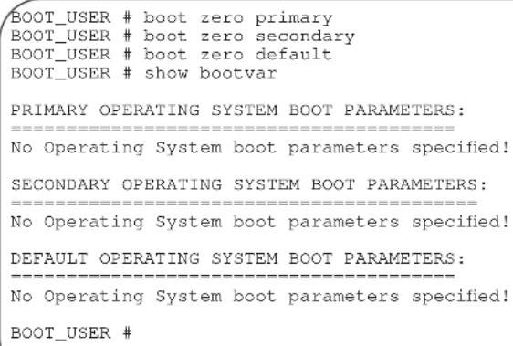
Related Commands
| boot change | Change the primary, secondary or default boot image configuration |
| show boot selection | Display the current Boot Flash image selected. |
default-gateway

Assign an IP address as the default gateway for the system.
Syntax
[no] default-gateway ip-address
| Parameters | ip-address | Enter the IP address of the gateway router in dotted decimal format (A.B.C.D). |
| Defaults | Not configured. | |
| Command Modes | BOOT_USER | |
| Command History | Version 7.8.1.0 Introduced on S-Series | |
| Usage Information | Use the show default-gateway command to view the current default gateway. | |
| Related Commands | show default-gateway Change the primary, secondary or default boot image configuration | |
| show boot selection Display the current Boot Flash image selected. | ||
delete

Erase a file on the internal or external Flash.
Syntax
delete file-url
| Parameters | file-url | Enter the location keywords and information: | |
| • For a file on the internal Flash, enter | flash:// followed by the filename. | ||
| • For a file on the external Flash, enter | slot0:// followed by the filename. | ||
Defaults
Not configured.
Command Modes
BOOT_USER
dir

Display files in a directory
Syntax
dir file-url
Parameters
file-url
Enter the location keywords and information:
- For a file on the internal Flash, enter flash:// followed by the filename.
- For a file on the external Flash, enter slot0:// followed by the filename.
Defaults
Not configured.
Command Modes
BOOT_USER
Usage Information
The maximum number of files allowed on an MMC card (internal or external flash) is 100 files.
Example
Figure 4-4. dir Command Example
| BOOT_USER # dir flash: | |||
| Displaying files in flash: | |||
| size | date | time | name |
| 8681647 | MAR-21-2004 | 11:08:50 | E1200-3.1.a3.78.bin |
| 4905 | MAR-17-2004 | 18:16:34 | nimule |
| 1182431 | FEB-29-2004 | 22:08:14 | dohuk |
| 8807825 | MAR-30-2004 | 12:49:14 | E1200-3.1.0.309.bin |
| 1182431 | FEB-24-2004 | 22:52:00 | t1 |
| 14729 | MAR-14-2004 | 17:55:26 | erbil |
| 1182431 | MAR-10-2004 | 10:57:30 | vW |
| 6858 | MAR-07-2004 | 09:52:58 | RPMOCP1 |
| 1182431 | MAR-22-2004 | 12:17:34 | tunis |
| 7819238 | MAR-22-2004 | 12:23:14 | E1200-3.1.0.316.bin |
| 8989646 | MAR-17-2004 | 15:13:06 | E1200-3.1.0.390.bin.dos2 |
| 14517 | MAR-30-2004 | 09:48:44 | RPMOCPlog1 |
| 14506 | MAR-30-2004 | 09:49:34 | RPMOCPlog2 |
| BOOT_USER # | |||
enable

Change the privilege level of user access to FTOS commands.
Syntax
enable {user | admin}
Parameters
admin Used only by Dell Force10 TAC personnel.
user
Used only by Dell Force10 TAC personnel.
Defaults
Not configured.
Command Modes
BOOT_USER
Usage Information
Only Dell Force10 TAC staff use this command.
format

Format the internal or external flash memory.
Syntax
format file-url
Parameters
| file-url | Enter the location keywords and information: | |
| For a file on the internal Flash, enter | flash:// followed by the filename. | |
| For a file on the external Flash, enter | slot0:// followed by the filename. | |
Defaults
Not configured.
Command Modes
BOOT_ADMIN
Usage Information
The maximum number of files allowed on an MMC card (internal or external flash) is 100 files.
Related Commands
| format (C-Series and E-Series) | Erase all existing files and reformat a filesystem (EXEC Privilege mode). |
| show file | Display contents of a text file in the local filesystem. |
| show file-systems | Display information about the file systems on the system. |
ignore enable-password

Reload the system software without the enable password configured. This command is hidden on the C-Series and E-Series, so it is not listed when you enter ? or help in this mode.
Syntax
ignore enable-password
Defaults
Not configured.
Command Modes
BOOT_USER
Command History
Version 7.8.1.0 Introduced on S-Series
Usage Information
When you enter the reload command and the system reboots, you will not be prompted for a password to enter the EXEC Privilege mode (normally you are required to enter the enable command.)
If your console or Telnet session expires after you used the ignore enable-password command, you are prompted for an enable password when you re-establish the session.
Related Commands
reload
Exit from this mode and reload FTOS.
show running-config Display the current configuration and the changes from the default values.
ignore startup-config

During a reload, do not load the startup-config file.
Syntax
ignore startup-config
Defaults
disabled
Command Modes
BOOT_USER
Command
History
Version 7.8.1.0 Introduced on S-Series
Usage
Information
This command might be used if a the user has authentication procedures in the startup-config other than the enable-password setting.
interface management ethernet ip address

Assign an IP address to the Management Ethernet interface.
Syntax
[no] interface management ethernet ip address ip-address mask
To delete the IP address on the C-Series and E-Series (not on S-Series), enter no interface management ethernet ip address.
Parameters
ip-address mask
Enter the IP address in dotted decimal format (A.B.C.D) and the mask in /prefix-length format (/x).
Defaults
Not configured.
Command Modes
BOOT_USER
Command
History
Version 7.8.1.0 Introduced on S-Series
Usage
Information
In the runtime CLI of the C-Series and E-Series (not on S-Series), use the ip address command in the INTERFACE mode to change the Management interface's IP address.
If there is a mac address programmed in the eeprom, the show interface management ethernet command gets the mac address from there and displays it. If there is no mac address programmed, the following is used by default - 00:10:18:00:00:01.
To view the current IP address configured on the Management interface, enter the show interfaces management ethernet command.
Related
Commands
ip address Assign a primary and secondary IP address to the interface.
show default-gateway
Display the IP address configured for the default gateway.
show interface
Display the IP address configured for the Management interface.
management ethernet
interface management ethernet mac-address

Assign a MAC address to the Management Ethernet interface.
Syntax
interface management ethernet mac-address mac-address
| Parameters | mac-address | Enter a MAC address in standard format (xx:xx:xx:xx:xx:xx). |
| Defaults | Not configured. | |
| Command Modes | BOOT_USER | |
| Command History | Version 7.8.1.0 Introduced on S-Series | |
| Usage Information | Use this command to assign a MAC address if FTOS cannot find a default MAC address. | |
| Related Commands | show default-gateway | Display the IP address configured for the default gateway. |
| show interface management ethernet | Display the IP address configured for the Management interface. | |
interface management ethernet port

Assign a port to be the Management Ethernet interface.
Syntax
interface management ethernet port portID
| Parameters | portID | Enter an S-Series port ID as an integer. Range: 1 to 48 |
| Defaults | Not configured. | |
| Command Modes | BOOT_USER | |
| Command History | Version 7.8.1.0 Introduced on S-Series | |
| Usage Information | Assign any copper port to be the Management Ethernet interface. | |
| Related Commands | show interface management ethernet | Display the IP address configured for the Management interface. |
interface management port config

Configure speed, duplex, and negotiation settings for the management interface.
Syntax
interface management port config {half-duplex | full-duplex | 10m | 100m | auto-negotiation | no auto-negotiation | show}
Parameters
| half-duplex | Enter the keyword half-duplex to set the Management interface to half-duplex mode. |
| full-duplex | Enter the keyword full-duplex to set the Management interface to full-duplex mode. |
| 10m | Enter the keyword 10m to set the speed on the Management interface to 10 Mb/s. |
| 100m | Enter the keyword 100m to set the speed of the Management interface to 100 Mb/s. |
| auto-negotiation | Enter the keyword auto-negotiation to enable negotiation on the Management interface. |
| no auto-negotiation | Enter the keyword no auto-negotiation to disable auto-negotiation on the Management interface. |
| show | Enter the keyword show to display the settings on the Management interface. |
Defaults
full duplex; auto-negotiation
Command Modes
BOOT_USER
Usage Information
This command is only available in Boot Flash version 2.0.0.21 and higher.
Related Commands
| show default-gateway | Display the IP address configured for the default gateway. |
| show interface management ethernet | Display the IP address configured for the Management interface. |
reload

Exit from this mode and reload FTOS.
Syntax
reload
Command Modes
BOOT_USER
Command History
Version 7.8.1.0 Introduced on S-Series
Related Commands
save
Save configurations created in BOOT_USER mode (BLI).
rename

Rename a file.
Syntax
rename file-url
| Parameters | file-url | Enter the location keywords and information:For a file on the internal Flash, enter flash:// followed by the filename.For a file on the external Flash, enter slot0:// followed by the filename. |
Defaults None.
Command Modes BOOT_USER
restore factory-defaults
S Erase all NVRAM sectors, EEPROM sectors, and user boot configurations.
Syntax restore factory-defaults
Command Modes BOOT_USER
Command History Version 7.8.1.0 Introduced on S-Series
save
S Save configurations created in BOOT_USER mode (BLI).
Command History Version 7.8.1.0 Introduced on S-Series
Usage Information A basic difference between S-Series and other Dell Force10 platforms is that, on the S-Series, FTOS does not save configurations into NVRAM while the user enters them in the BLI. Instead, the configurations are saved in a software cache and are written into NVRAM only on the execution of this save command or of the reload command.
Related Commands reload Exit from this mode and reload FTOS. write Save the running configuration to the startup configuration file.
show boot selection
C E Display the current FTOS boot image.
Syntax show boot selection
Command Modes BOOT_USER
Example
Figure 4-5. show boot selection Command Example
| BOOT_USER # show boot selection |
| ROM BOOTSTRAP SELECTOR PARAMETERS: |
| Current ROM bootstrap selection set to Bootflash partition B. |
| Last ROM bootstrap occurred from Bootflash partition B. |
| BOOT_USER # |
Related Commands
| boot change | Change the primary, secondary or default boot image configuration |
| boot selection | Change the boot flash image on the internal Flash. |
show bootflash

Display information on the boot flash.
Syntax
show bootflash
Command Modes
BOOT_USER
Example
Figure 4-6. show bootflash Command Example
| BOOT_USER # show bootflash |
| GENERAL BOOTFLASH INFO |
| Botflash Partition A:Force10 Networks System BootCopyright 1999-2004 Force10 Networks, Inc.ROM Header Version 1.0Engineering CP_IMG_BOOT, BSP Release 2.0.0.19, Checksum 0x39303030Created Mon Mar 20 10:56:53 US/Pacific 2004 by xxx on Unknown host |
| Bootflash Partition B:Force10 Networks System BootCopyright 1999-2004 Force10 Networks, Inc.ROM Header Version 1.0Engineering CP_IMG_BOOT, BSP Release 2.0.0.19, Checksum 0x36313031Created Mon Mar 6 18:15:10 2004 by xxx on hostname |
| Boot Selector Partition:Force10 Networks System BootCopyright 1999-2004 Force10 Networks, Inc.ROM Header Version 1.0Official CP_IMG_BOOT_SELECTOR, BSP Release 2.0.0.15, Checksum 0x30314348Created Mon Jan 21 17:15:47 US/Pacific 2004 by xxx on Unknown host |
| BOOT_USER # |
show bootvar

Display boot configuration information.
Syntax
show bootvar
Command Modes
BOOT_USER
Command History
Version 7.8.1.0 Introduced on S-Series
Example
Figure 4-7. show bootvar Command Example
BOOT_USER # show bootvar

PRIMARY OPERATING SYSTEM BOOT PARAMETERS:
====================
boot device : ftp
file name : tt/latestlabel
Management Ethernet IP address : 10.16.1.181/24
Server IP address : 10.16.1.209
username : amsterdam
password : *****
SECONDARY OPERATING SYSTEM BOOT PARAMETERS:
====================
boot device : flash
file name : /E1200-3.1.1.3.bin
DEFAULT OPERATING SYSTEM BOOT PARAMETERS:
====================
boot device : flash
file name : /E1200-3.1.1.2.bin
BOOT_USER #
Related Commands
boot change
Change the primary, secondary or default boot image configuration.
boot zero Erase the configured primary, secondary, or default boot image parameters.
show default-gateway

Display the IP address configured for the default gateway.
Syntax
show default-gateway
Command Mode
BOOT_USER
Command History
Version 7.8.1.0 Introduced on S-Series
Example
Figure 4-8. show default-gateway Command Example
BOOT_USER # show default-gateway
Gateway IP address: 10.1.1.1
BOOT_USER #
Related Commands
default-gateway
Configure the IP address for the default gateway.
interface management ethernet ip address
Assign an IP address to the Management Ethernet interface.
show interface management ethernet

Display the IP address configured for the Management interface.
Syntax
show interface management ethernet
Command Modes
BOOT_USER
Command History
Version 7.8.1.0 Introduced on S-Series
Example
Figure 4-9. show interface management ethernet Command Example
BOOT_USER # show interfaces management ethernet
Management ethernet IP address: 10.16.1.181/24
BOOT_USER #
On the S-Series, the output of this command includes the MAC address and port number of the assigned management port.
Example
Figure 4-10. show interface management ethernet Command Example
BOOT_USER # show interface management ethernet
Management ethernet IP address: 10.16.1.181/24
Management ethernet MAC address: 00:01:e8:43:13:16
Management ethernet port number: 1
BOOT_USER #
Related Commands
interface management ethernet ip address
Assign an IP address to the Management Ethernet interface.
interface management port config Configure speed, duplex, and negotiation settings for the management interface.
Control and Monitoring
Overview
This chapter contains the following commands to configure and monitor the system, including Telnet, FTP, and TFTP as they apply to platforms C E S.
Commands
| audible cut-off send | |
| banner exec service timestamps | |
| banner login show alarms | |
| banner motd show chassis | |
| cam-audit linecard show command-history | |
| clear alarms show command-tree | |
| clear command history show console lp | |
| clear line show cpu-traffic-stats | |
| configure show debugging | |
| debug cpu-traffic-stats show environment (C-Series and E-Series) | |
| debug ftpserver show environment (S-Series) | |
| disable show inventory (C-Series and E-Series) | |
| do show inventory (S-Series) | |
| enable | show linecard |
| enable xfp-power-updates | show linecard boot-information |
| end | show memory (C-Series and E-Series) |
| epoch | show memory (S-Series) |
| exec-banner show processes cpu (C-Series and E-Series) | |
| exec-timeout | show processes cpu (S-Series) |
| exit | show processes ipc flow-control |
| ftp-server topdir | show processes memory (C-Series and E-Series) |
| ftp-server username | show processes memory (S-Series) |
| hostname show rpm | |
| ip ftp password show software ifm | |
| ip ftp source-interface show switch links | |
| ip ftp username show system (S-Series) | |
| ip telnet server enable show tech-support (C-Series and E-Series) | |
| ip telnet source-interface show tech-support (S-Series) | |
| ip tftp source-interface ssh-peer-rpm | |
| line telnet | |
| linecard telnet-peer-rpm | |
| module power-off terminal length | |
| motd-banner terminal xml | |
| ping traceroute | |
| power-off undbug all | |
| power-on upload trace-log | |
| reload virtual-ip | |
| reset write | |
| rpmlocation-led | |
audible cut-off

Turn off an audible alarm.
Syntax
audible cut-off
Defaults
Not configured.
Command Modes
EXEC Privilege
banner exec

Configure a message that is displayed when a user enters the EXEC mode.
Syntax
banner exec c line c
Parameters
| c | Enter the keywordsbanner exec, and then enter a character delineator, represented here by the letter c, and press ENTER. |
| line | Enter a text string for your banner message ending the message with your delineator.In the example below, the delineator is a percent character (%); the banner message is “testing, testing”. |
Defaults
No banner is displayed.
Command Modes
CONFIGURATION
Command History
| Version 8.1.1.0 | Introduced on E-Series ExaScale |
| Version 7.6.1.0 | Introduced on S-Series |
Version 7.5.1.0 Introduced on C-Series
E-Series original Command
Usage Information
Optionally, use the banner exec command to create a text string that is displayed when the user accesses the EXEC mode. The exec-banner command toggles that display.
Example
Force10(conf)#banner exec ?
LINE    c banner-text c, where 'c' is a delimiting character
Force10(conf)#banner exec %
Enter TEXT message. End with the character '%'.
This is the banner%
Force10(conf)#end
Force10#exit
4d21h5m: %RPM0-P:CP %SEC-5-LOGOUT: Exec session is terminated for user on line console
This is the banner
Force10 con0 now available
Press RETURN to get started.
4d21h6m: %RPM0-P:CP %SEC-5-LOGIN_SUCCESS: Login successful for user on line console
This is the banner
Force10>
Related Commands
banner login Sets a banner for login connections to the system.
banner motd Sets a Message of the Day banner.
exec-banner Enable the display of a text string when the user enters the EXEC mode.
line Enable and configure console and virtual terminal lines to the system.
banner login

Set a banner to be displayed when logging on to the system.
Syntax
banner login {keyboard-interactive | no keyboard-interactive} [c line c]
Parameters
keyboard-interactive Enter this keyword to require a carriage return (CR) to get the message banner prompt.
c Enter a delineator character to specify the limits of the text banner. In Figure 5-1, the % character is the delineator character.
line Enter a text string for your text banner message ending the message with your delineator.
In the example in Figure 5-1, the delineator is a percent character (%). Ranges:
• maximum of 50 lines
- up to 255 characters per line
Defaults
No banner is configured and the CR is required when creating a banner.
Command Modes
CONFIGURATION
Command History
Version 8.2.1.0 Introduced keyboard-interactive keyword
Version 8.1.1.0 Introduced on E-Series ExaScale
Version 7.6.1.0 Introduced on S-Series
Version 7.5.1.0 Introduced on C-Series
E-Series original Command
Usage Information
A login banner message is displayed only in EXEC Privilege mode after entering the enable command followed by the password. These banners are not displayed to users in EXEC mode.
Related Commands
banner exec Sets a banner to be displayed when you enter EXEC Privilege mode.
banner motd Sets a Message of the Day banner.
Example
Figure 5-1. Command Example: banner login
Force10(conf)#banner login ?
keyboard-interactive    Press enter key to get prompt
LINE    c banner-text c, where 'c' is a delimiting character
Force10(conf)#no banner login ?
keyboard-interactive    Prompt will be displayed by default
<cr>
Force10(conf)#banner login keyboard-interactive

Enter TEXT message. End with the character '%'.
This is the banner%
Force10(conf)#end
Force10#exit

13d21h9m: %RPM0-P:CP %SEC-5-LOGOUT: Exec session is terminated for user on line console

This is the banner

Force10 con0 now available

Press RETURN to get started.
13d21h10m: %RPM0-P:CP %SEC-5-LOGIN_SUCCESS: Login successful for user on line console

This is the banner
Force10>
banner motd

Set a Message of the Day (MOTD) banner.
Syntax
banner motd c line c
Parameters
| c | Enter a delineator character to specify the limits of the text banner. In the above figures, the % character is the delineator character. |
| line | Enter a text string for your message of the day banner message ending the message with your delineator.In the example figures above, the delineator is a percent character (%). |
Defaults
No banner is configured.
Command Modes
CONFIGURATION
| Command History | Version 8.1.1.0 Introduced on E-Series ExaScale |
| Version 7.6.1.0 Introduced on S-Series | |
| Version 7.5.1.0 Introduced on C-Series | |
| E-Series original Command | |
| Usage information | A MOTD banner message is displayed only in EXEC Privilege mode after entering the enable command followed by the password. These banners are not displayed to users in EXEC (non-privilege) mode. |
| Related Commands | banner exec Sets a banner to be displayed when you enter the EXEC Privilege mode. |
| banner login Sets a banner to be displayed after successful login to the system. |
cam-audit linecard
E Enable audit of the IPv4 forwarding table on all line cards.
Syntax cam-audit linecard all ipv4-fib interval time-in-minutes
| Parameters | all | Enter the keyword all to enable CAM audit on all line cards. |
| ipv4-fib | Enter the keyword ipv4-fib to designate the CAM audit on the IPv4 forwarding entries. | |
| interval time-in-minutes | Enter the keyword interval followed by the frequency in minutes of the CAM audit.Range: 5 to 1440 minutes (24 hours)Default: 60 minutes | |
| Defaults | Disabled | |
| mand Modes | CONFIGURATION | |
| Command History | Version 7.4.1.0 Introduced on E-Series | |
| Usage Information | Enables periodic audits of software and hardware copies of the IPv4 forwarding table. | |
clear alarms
C E S Clear alarms on the system.
Syntax clear alarms
Command Modes EXEC Privilege
| Command History | Version 8.1.1.0 Introduced on E-Series ExaScale | |
| Version 7.6.1.0 Introduced on S-Series | ||
| Version 7.5.1.0 Introduced on C-Series | ||
| E-Series original Command | ||
| Usage Information | This command clear alarms that are no longer active. If an alarm situation is still active, it is seen in the system output. | |
| clear command history | ||
| C E S | Clear the command history log. | |
| Syntax | clear command history | |
| Command Modes | EXEC Privilege | |
| Command History | Version 8.1.1.0 Introduced on E-Series ExaScale | |
| Version 7.6.1.0 Introduced on S-Series | ||
| Version 7.5.1.0 Introduced on C-Series | ||
| E-Series original Command | ||
| Related Commands | show command-history | Display a buffered log of all commands entered by all users along with a time stamp. |
| clear line | ||
| C E S | Reset a terminal line. | |
| Syntax | clear line {line-number | aux 0 | console 0 | vty number} | |
| Parameters | line-number | Enter a number for one of the 12 terminal lines on the system. Range: 0 to 11. |
| aux 0 Enter the keywords aux 0 to reset the Auxiliary port. Note: This option is supported on E-Series only. | ||
| console 0 | Enter the keyword console 0 to reset the Console port. | |
| vty number | Enter the keyword vty followed by a number to clear a Terminal line. Range: 0 to 9 | |
| Command Modes | EXEC Privilege | |
| Command History | Version 8.1.1.0 Introduced on E-Series ExaScale | |
| Version 7.6.1.0 Introduced on S-Series | ||
| Version 7.5.1.0 Introduced on C-Series | ||
| E-Series original Command | ||
configure

Enter the CONFIGURATION mode from the EXEC Privilege mode.
Syntax
configure [terminal]
Parameters
| terminal | (OPTIONAL) Enter the keyword terminal to specify that you are configuring from the terminal. |
Command Modes
| EXEC Privilege |
| Version 8.1.1.0 Introduced on E-Series ExaScale |
| Version 7.6.1.0 Introduced on S-Series |
| Version 7.5.1.0 Introduced on C-Series |
| E-Series original Command |
Command History
Example
Figure 5-2. Command Example: configure
| Force10#configure |
| Force10 (conf)# |
debug cpu-traffic-stats

Enable the collection of CPU traffic statistics.
Syntax
debug cpu-traffic-stats
Defaults
Disabled
Command Modes
EXEC Privilege
Command History
| Version 7.6.1.0 Introduced on S-Series |
| Version 7.5.1.0 Introduced on C-Series |
| Version 6.2.1.1 Introduced on E-Series |
Usage Information
This command enables (and disables) the collection of CPU traffic statistics from the time this command is executed (not from system boot). However, excessive traffic received by a CPU will automatically trigger (turn on) the collection of CPU traffic statics. The following message is an indication that collection of CPU traffic is automatically turned on. Use the show cpu-traffic-stats to view the traffic statistics.
Excessive traffic is received by CPU and traffic will be rate controlled.

Note: This command must be enabled before the show cpu-traffic-stats command will display traffic statistics. Dell Force10 recommends that you disable debugging (no debug cpu-traffic-stats) once troubleshooting is complete.
Related Commands
show cpu-traffic-stats Display cpu traffic statistics
debug ftpserver

View transactions during an FTP session when a user is logged into the FTP server.
Syntax
debug ftpserver
Command Modes
EXEC Privilege
Command History
Version 8.1.1.0 Introduced on E-Series ExaScale
Version 7.6.1.0 Introduced on S-Series
Version 7.5.1.0 Introduced on C-Series
E-Series original Command
disable

Return to the EXEC mode.
Syntax
disable [level]
Parameters
level
(OPTIONAL) Enter a number for a privilege level of the FTOS.
Range: 0 to 15.
Default: 1
Defaults
1
Command Modes
EXEC Privilege
Command History
Version 8.1.1.0 Introduced on E-Series ExaScale
Version 7.6.1.0 Introduced on S-Series
Version 7.5.1.0 Introduced on C-Series
E-Series original Command
do

Allows the execution of most EXEC-level commands from all CONFIGURATION levels without returning to the EXEC level.
Syntax
do command
Parameters
command
Enter an EXEC-level command.
Defaults
No default behavior
Command Modes
CONFIGURATION
INTERFACE
Command History
Version 8.1.1.0 Introduced on E-Series ExaScale
Version 7.6.1.0 Introduced on S-Series
Version 7.5.1.0 Introduced on C-Series
Version 6.1.1.0 Introduced on E-Series
Usage Information
The following commands are not supported by the do command:
- enable
- disable
- exit
- config
Example
Figure 5-3. Command Example: do
Force10(conf-if-te-5/0)#do clear counters
Clear counters on all interfaces [confirm]
Force10(conf-if-te-5/0)#
Force10(conf-if-te-5/0)#do clear logging
Clear logging buffer [confirm]
Force10(conf-if-te-5/0)#
Force10(conf-if-te-5/0)#do reload
System configuration has been modified. Save? [yes/no]: n
Proceed with reload [confirm yes/no]: n
Force10(conf-if-te-5/0)#
enable

Enter the EXEC Privilege mode or any other privilege level configured. After entering this command, you may need to enter a password.
Syntax
enable [level]
Parameters
level
(OPTIONAL) Enter a number for a privilege level of FTOS.
Range: 0 to 15.
Default: 15
Defaults
15
Command Modes
EXEC
Command History
Version 8.1.1.0 Introduced on E-Series ExaScale
Version 7.6.1.0 Introduced on S-Series
Version 7.5.1.0 Introduced on C-Series
E-Series original Command
Usage Information
Users entering the EXEC Privilege mode or any other configured privilege level can access configuration commands. To protect against unauthorized access, use the enable password command to configure a password for the enable command at a specific privilege level. If no privilege level is specified, the default is privilege level 15.
Related Commands
enable password Configure a password for the enable command and to access a privilege level.
enable xfp-power-updates
| C E S | Enable XFP power updates for SNMP. | |
| Syntax | enable xfp-power-updates interval secondsTo disable XFP power updates, use the no enable xfp-power-updates command. | |
| Parameters | interval seconds | Enter the keyword interval followed by the polling interval in seconds.Range: 120 to 6000 secondsDefault: 300 seconds (5 minutes) |
| Defaults | Disabled | |
| Command Modes | CONFIGURATION | |
| Command History | Version 8.1.1.0 Introduced on E-Series ExaScale | |
| Version 7.6.1.0 Introduced on S-Series | ||
| Version 7.5.1.0 Introduced on C-Series and E-Series | ||
| Usage Information | The chassis MIB contain the entry chSysXfpRecvPower in the chSysPortTable table. Periodically, IFA polls the XFP power for each of the ports, and sends the values to IFM where it is cached. The default interval for the polling is 300 seconds (5 minutes). Use this command to enable the polling and to configure the polling frequency. | |
| end | ||
| C E S | Return to the EXEC Privilege mode from other command modes (for example, the CONFIGURATION or ROUTER OSPF modes). | |
| Syntax | end | |
| Command Modes | CONFIGURATION, SPANNING TREE, MULTIPLE SPANNING TREE, LINE, INTERFACE, TRACE-LIST, VRRP, ACCESS-LIST, PREFIX-LIST, AS-PATH ACL, COMMUNITY-LIST, ROUTER OSPF, ROUTER RIP, ROUTER ISIS, ROUTER BGP | |
| Command History | Version 8.1.1.0 Introduced on E-Series ExaScale | |
| Version 7.6.1.0 Introduced on S-Series | ||
| Version 7.5.1.0 Introduced on C-Series | ||
| E-Series original Command | ||
| Related Commands | exit Return to the lower command mode. | |
epoch

Set the epoch scheduling time for the chassis.
Syntax
epoch {2.4 |3.2 | 10.4}
| Parameters | 2.4 | Enter the keyword 2.4 to set the epoch to 2.4 micro-seconds and lower the latency.This option is available on the E600i and E1200i E-Series ExaScale systems only. |
| 3.2 | Enter the keyword 3.2 to set the epoch to 3.2 micro-seconds and lower the latency.This option is available on the E600/E600i and E1200/E1200i only. ExaScale does not supports this setting with FTOS 8.3.1.0 and later. | |
| 10.4 | Enter the keyword 10.4 to set the epoch to 10.4 micro-seconds.This is the default setting and is available on the E300, E600/E600i, and E1200. |
Defaults
10.4
Command Modes
CONFIGURATION
| Command History | Version 8.3.1.0 Added 2.4 micro-seconds option. ExaScale supports only 10.4 microseconds and 2.4 microseconds with FTOS 8.3.1.0 and later. |
| Version 8.1.1.2 Introduced on E-Series ExaScale E600i | |
| Version 8.1.1.0 Introduced on E-Series ExaScale E1200i | |
| Version 6.2.1.1 Support for E300 introduced (10.4 only) | |
| Version 6.1.1.0 Values changed as described above |
Usage Information
You save the configuration and reload the chassis for the changes to the epoch command setting to take affect.
When using 10 SFMs in an ExaScale chassis, the 10.4 and 2.4 settings are both line rate. Additionally, the 2.4 setting has a lower latency.
When using 9 SFMs in an ExaScale chassis, the 10.4 setting is line rate; the 2.4 setting reduces throughput. Dell Force10 recommends using the 10.4 setting when the system has 9 SFMs.
Using 8 SFMs in an ExaScale chassis reduces throughput at any epoch setting.
Note: The E300 supports only the 10.4 epoch setting. The E-Series TeraScale E600/E600i and the E1200/E1200i systems support the 10.4 and the 3.2 epoch settings.
Note: For E-Series ExaScale, the 2.4 setting is supported on FTOS version 8.3.1.0 and later. The 10.4 setting is supported on all ExaScale FTOS versions. The 3.2 setting is only supported on FTOS versions 8.2.1.0 and earlier.
exec-banner
C E S Enable the display of a text string when the user enters the EXEC mode.
Syntax exec-banner
Defaults Enabled on all lines (if configured, the banner appears).
Command Modes LINE
| Command History | Version 8.1.1.0 Introduced on E-Series ExaScale |
| Version 7.6.1.0 Introduced on S-Series | |
| Version 7.5.1.0 Introduced on C-Series | |
| E-Series original Command |
Usage Optionally, use the banner exec command to create a text string that is displayed when the user accesses the EXEC mode. This command toggles that display.
| Related Commands | banner exec Configure a banner to display when entering the EXEC mode. |
| line Enable and configure console and virtual terminal lines to the system. |
exec-timeout
C E S Set a time interval the system will wait for input on a line before disconnecting the session.
Syntax exec-timeout minutes [seconds]
To return to default settings, enter no exec-timeout.
| Parameters | |
| minutesEnter the number of minutes of inactivity on the system before disconnecting the current session.Range: 0 to 35791Default: 10 minutes for console line; 30 minutes for VTY line. | |
| seconds(OPTIONAL) Enter the number of secondsRange: 0 to 2147483Default: 0 seconds | |
Defaults 10 minutes for console line; 30 minutes for VTY lines; 0 seconds
Command Modes LINE
| Command History | Version 7.6.1.0 Introduced on S-Series |
Usage Information To remove the time interval, enter exec-timeout 0 0.
Example
Figure 5-4. FTOS time-out display
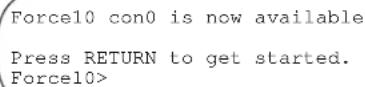
exit

Return to the lower command mode.
Syntax
exit
Command Modes
EXEC Privilege, CONFIGURATION, LINE, INTERFACE, TRACE-LIST, PROTOCOL GVRP, SPANNING TREE, MULTIPLE SPANNING TREE, MAC ACCESS LIST, ACCESS-LIST, AS-PATH ACL, COMMUNITY-LIST, PREFIX-LIST, ROUTER OSPF, ROUTER RIP, ROUTER ISIS, ROUTER BGP
Command History
Version 8.1.1.0 Introduced on E-Series ExaScale
Version 7.6.1.0 Introduced on S-Series
Version 7.5.1.0 Introduced on C-Series
E-Series original Command
Related Commands
end Return to the EXEC Privilege command mode.
ftp-server enable

Enable FTP server functions on the system.
Syntax
ftp-server enable
Defaults
Disabled.
Command Modes
CONFIGURATION
Command History
Version 8.1.1.0 Introduced on E-Series ExaScale
Version 7.6.1.0 Introduced on S-Series
Version 7.5.1.0 Introduced on C-Series
E-Series original Command
Example
Figure 5-5. Example of Logging on to an FTP Server
| morphous$ ftp 10.31.1.111 Connected to 10.31.1.111. 220 Force10 (1.0) FTP server ready Name (10.31.1.111:dch): dch 331 Password required Password: 230 User logged in ftp> pwd 257 Current directory is "flash:" ftp> dir 200 Port set okay 150 Opening ASCII mode data connection size date time name ----- ---- ---- ---- ---- 512 Jul-20-2004 18:15:00 tgting 512 Jul-20-2004 18:15:00 diagnostic 512 Jul-20-2004 18:15:00 other 512 Jul-20-2004 18:15:00 tgt 226 Transfer complete 329 bytes received in 0.018 seconds (17.95 Kbytes/s) ftp> |
Related Commands
ftp-server topdir Set the directory to be used for incoming FTP connections to the E-Series.
ftp-server username Set a username and password for incoming FTP connections to the E-Series.
ftp-server topdir

Specify the top-level directory to be accessed when an incoming FTP connection request is made.
Syntax
ftp-server topdir directory
Parameters
directory Enter the directory path.
Defaults
The internal flash is the default directory.
Command Modes
CONFIGURATION
Command History
Version 8.1.1.0 Introduced on E-Series ExaScale
Version 7.6.1.0 Introduced on S-Series
Version 7.5.1.0 Introduced on C-Series
E-Series original Command
Usage Information
After you enable FTP server functions with the ftp-server enable command, Dell Force10 recommends that you specify a top-level directory path. Without a top-level directory path specified, the FTOS directs users to the flash directory when they log in to the FTP server.
Related Commands
ftp-server enable Enables FTP server functions on the E-Series.
ftp-server username Set a username and password for incoming FTP connections to the E-Series.
ftp-server username

Create a user name and associated password for incoming FTP server sessions.
Syntax
ftp-server username username password [encryption-type] password
| Parameters | username | Enter a text string up to 40 characters long as the user name. |
| password password | Enter the keyword password followed by a string up to 40 characters long as the password.Without specifying an encryption type, the password is unencrypted. | |
| encryption-type | (OPTIONAL) After the keyword password enter one of the following numbers:0 (zero) for an unencrypted (clear text) password7 (seven) for hidden text password. | |
| Defaults | Not enabled. | |
| hand Modes | CONFIGURATION | |
| Command History | Version 8.1.1.0 Introduced on E-Series ExaScale | |
| Version 7.6.1.0 Introduced on S-Series | ||
| Version 7.5.1.0 Introduced on C-Series | ||
| E-Series original Command | ||
hostname

Set the host name of the system.
Syntax
hostname name
| Parameters | name | Enter a text string, up to 32 characters long. |
| Defaults | Force10 | |
| mand Modes | CONFIGURATION | |
| Command History | Version 8.1.1.0 Introduced on E-Series ExaScale | |
| Version 7.6.1.0 Introduced on S-Series | ||
| Version 7.5.1.0 Introduced on C-Series | ||
| E-Series original Command | ||
Usage Information
The hostname is used in the prompt.
ip ftp password
| Syntax | Specify a password for outgoing FTP connections | |
| ip ftp password [encryption-type] password | ||
| Parameters | encryption-type | (OPTIONAL) Enter one of the following numbers:0 (zero) for an unencrypted (clear text) password7 (seven) for hidden text password |
| password | Enter a string up to 40 characters as the password. | |
| Defaults | Not configured. | |
| Command Modes | CONFIGURATION | |
| Command History | Version 8.1.1.0 Introduced on E-Series ExaScale | |
| Version 7.6.1.0 Introduced on S-Series | ||
| Version 7.5.1.0 Introduced on C-Series | ||
| E-Series original Command | ||
| Usage Information | The password is listed in the configuration file; you can view the password by entering theshow running-config ftpcommand. | |
| The password configured by the ip ftp password command is used when you use theftp: parameter in thecopycommand. | ||
| Related Commands | copy Copy files. | |
| ip ftp username Set the user name for FTP sessions. | ||
ip ftp source-interface

Specify an interface's IP address as the source IP address for FTP connections.
Syntax
ip ftp source-interface interface
| Parameters | interface | Enter the following keywords and slot/port or number information:For an 100/1000 Ethernet interface, enter the keywordGigabitEthernetfollowed by the slot/port information.For a 1-Gigabit Ethernet interface, enter the keywordGigabitEthernetfollowed by the slot/port information.For Loopback interfaces, enter the keywordloopbackfollowed by a number from zero (0) to 16383.For a Port Channel interface, enter the keywordport-channelfollowed by a number:C-Series and S-Series: 1-128E-Series: 1 to 32 for EtherScale, 1 to 255 for TeraScale and 1 to 512 for ExaScaleFor SONET interface types, enter the keywordsonetfollowed by the slot/port information.For a 10-Gigabit Ethernet interface, enter the keywordTenGigabitEthernet followed by the slot/port information.For a VLAN interface, enter the keywordvlanfollowed by a number from 1 to 4094. |
| Defaults | The IP address on the system that is closest to the Telnet address is used in the outgoing packets. | |
| Command Modes | CONFIGURATION | |
| Command History | Version 8.2.1.0 Increased number of VLANs on ExaScale to 4094 (was 2094) | |
| Version 8.1.1.0 Introduced on E-Series ExaScale | ||
| Version 7.6.1.0 Support added for S-Series | ||
| Version 7.5.1.0 Introduced on C-Series | ||
| E-Series original Command | ||
| Related Commands | copyCopy files from and to the switch. | |
ip ftp username

Assign a user name for outgoing FTP connection requests.
Syntax
ip ftp username username
| Parameters | username | Enter a text string as the user name up to 40 characters long. |
| Defaults | No user name is configured. | |
| Command Modes | CONFIGURATION | |
| Command History | Version 8.1.1.0 Introduced on E-Series ExaScale | |
| Version 7.6.1.0 Introduced on S-Series | ||
| Version 7.5.1.0 Introduced on C-Series | ||
| E-Series original Command | ||
| Usage Information | You must also configure a password with the ip ftp password command. | |
| Related Commands | ip ftp password Set the password for FTP connections. | |
ip telnet server enable

Enable the Telnet server on the switch.
Syntax
ip telnet server enable
To disable the Telnet server, execute the no ip telnet server enable command.
Defaults
Enabled
Command Modes
CONFIGURATION
Command History
Version 8.1.1.0 Introduced on E-Series ExaScale
Version 7.6.1.0 Support added for S-Series
Version 7.5.1.0 Introduced on C-Series
Version 6.1.1.0 Introduced on E-Series
Related Commands
ip ssh server
Enable SSH server on the system.
ip telnet source-interface

Set an interface's IP address as the source address in outgoing packets for Telnet sessions.
Syntax
ip telnet source-interface interface
Parameters
interface
Enter the following keywords and slot/port or number information:
- For an 100/1000 Ethernet interface, enter the keyword the slot/port information.
- For a 1-Gigabit Ethernet interface, enter the keyword slot/port information.
- For Loopback interfaces, enter the keyword (0) to 16383.
- For the SONET interfaces, enter the keyword
- For a Port Channel, enter the keyword C-Series and S-Series: 1-128
GigabitEthernet followed by
GigabitEthernet followed by the
loopback followed by a number from zero
sonet followed by slot/port information.
port-channel followed by a number:
C-Series and S-Series: 1-128
E-Series: 1 to 32 for EtherScale, 1 to 255 for TeraScale and 1 to 512 for ExaScale
- For a 10-Gigabit Ethernet interface, enter the keyword by the slot/port information.
- For VLAN interface, enter the keyword
TenGigabitEthernet followed
vlan followed by a number from 1 to 4094.
| Defaults | The IP address on the system that is closest to the Telnet address is used in the outgoing packets. |
| Command Modes | CONFIGURATION |
| Command History | Version 8.2.1.0 Increased number of VLANs on ExaScale to 4094 (was 2094) |
| Version 8.1.1.0 Introduced on E-Series ExaScale | |
| Version 7.6.1.0 Support added for S-Series | |
| Version 7.5.1.0 Introduced on C-Series | |
| E-Series original Command | |
| Related Commands | telnet Telnet to another device. |
ip tftp source-interface

Assign an interface's IP address in outgoing packets for TFTP traffic.
Syntax
ip tftp source-interface interface
Parameters
interface
Enter the following keywords and slot/port or number information:
- For an 100/1000 Ethernet interface, enter the keyword the slot/port information.
GigabitEthernet followed by
- For a 1-Gigabit Ethernet interface, enter the keyword slot/port information.
GigabitEthernet followed by the
- For Loopback interfaces, enter the keyword (0) to 16383.
loopback followed by a number from zero
- For a Port Channel, enter the keyword C-Series and S-Series: 1-128
port-channel followed by a number:
E-Series: 1 to 32 for EtherScale, 1 to 255 for TeraScale and 1 to 512 for ExaScale
- For the SONET interfaces, enter the keyword
sonet followed by slot/port information.
- For a 10-Gigabit Ethernet interface, enter the keyword by the slot/port information.
TenGigabitEthernet followed
- For a VLAN interface, enter the keyword
vlan followed by a number from 1 to 4094.
Defaults
The IP address on the system that is closest to the Telnet address is used in the outgoing packets.
Command Modes
CONFIGURATION
Command History
Version 8.2.1.0 Increased number of VLANs on ExaScale to 4094 (was 2094)
Version 8.1.1.0 Introduced on E-Series ExaScale
Version 7.6.1.0 Support added for S-Series
Version 7.5.1.0 Introduced on C-Series
E-Series original Command
line

Enable and configure console and virtual terminal lines to the system. This command accesses LINE mode, where you can set the access conditions for the designated line.
Syntax
line {aux 0 | console 0 | vty number [end-number]}
Parameters
| aux 0 | Enter the keyword aux 0 to configure the auxiliary terminal connection.Note: This option is supported on E-Series only. |
| console 0 | Enter the keyword console 0 to configure the console port.The console option for the S-Series is <0-0>. |
| vty number | Enter the keyword vty followed by a number from 0 to 9 to configure a virtual terminal line for Telnet sessions.The system supports 10 Telnet sessions. |
| end-number | (OPTIONAL) Enter a number from 1 to 9 as the last virtual terminal line to configure.You can configure multiple lines at one time. |
Defaults
Not configured
Command Modes
CONFIGURATION
Command History
| Version 8.1.1.0 Introduced on E-Series ExaScale |
| Version 7.6.1.0 Introduced on S-Series |
| Version 7.5.1.0 Introduced on C-Series |
| E-Series original Command |
Usage Information
You cannot delete a terminal connection.
Related Commands
| access-class | Restrict incoming connections to a particular IP address in an IP access control list (ACL). |
| password | Specify a password for users on terminal lines. |
| show linecard | Display the line card(s) status. |
linecard

Pre-configure a line card in a currently empty slot of the system or a different line card type for the slot.
Syntax
linecard number card-type
Parameters
| number | Enter the number of the slot. |
| C-Series Range: 0-7 | |
| E-Series Range: 0 to 13 on a E1200/E1200i, 0 to 6 on a E600/E6001, and 0 to 5 on a E300. | |
| card-type | Enter the line card ID (see the Supported Hardware section in the Release Notes). |
Defaults
Not configured
Command Modes
CONFIGURATION
Command History
Version 8.1.1.2 Introduced on E-Series ExaScale E600i
Version 8.1.1.0 Introduced on E-Series ExaScale E1200i
Version 7.5.1.0 Introduced on C-Series
E-Series original Command
Usage Information
Use this command only for empty slots or a slot where you have hot-swapped a different line card type. Before inserting a card of a different type into the pre-configured slot, execute the no linecard number command. The following screenshot shows the current supported C-Series line cards, along with their “card types” (card-type IDs).
Figure 5-6. Command Example: show linecard on Empty C300 Slot
Force10#show linecard 3
-- Line card 11 --
Status : not present

Force10#linecard 3 ?
E46TB 36-port GE 10/100/1000Base-T with RJ45 - 8-port FE/GE with SFP - 2-port 10GE with SFP+
E46VB 36-port GE 10/100/1000Base-T with RJ45 and PoE - 8-port FE/GE with SFP - 2-port 10GE with SFP+
E48PB 48-port FE/GE line card with SFP optics (CB)
E48TB 48-port GE 10/100/1000Base-T line card with RJ45 interfaces (CB)
E48VB 48-port GE 10/100/1000Base-T line card with RJ45 interfaces and PoE (CB)
EX4PB 4-port 10GE LAN PHY line card with XFP optics (CB)
EX8PB 8-port 10GE LAN PHY line card with XFP optics (CB)
Force10#linecard 3 EX4PB
Force10#show linecard 3

-- Line card 11 --
Status : not present
Required Type : EX4PB - 4-port 10GE LAN PHY line card with XFP optics (CB)
Force10#

Note: It is advisable to shut down interfaces on a line card that you are hot-swapping.
Related Commands
show linecard Display the line card(s) status.
module power-off

Turn off power to a line card at next reboot.
Syntax
module power-off linecard number
Parameters
linecard number Enter the keyword line card followed by the line card slot number
C-Series Range: 0-7
E-Series Range: 0 to 13 on a E1200/1200i, 0 to 6 on a E600/E600i, and 0 to 5 on a E300.
Defaults
Not configured.
Command Modes
CONFIGURATION
Command History
Version 8.1.1.2 Introduced on E-Series ExaScale E600i
Version 8.1.1.0 Introduced on E-Series ExaScale E1200i
Version 7.5.1.0 Introduced on C-Series
E-Series original Command
motd-banner

Enable a Message of the Day (MOTD) banner to appear when you log in to the system.
Syntax
motd-banner
Defaults
Enabled on all lines.
Command Modes
LINE
Command History
Version 8.1.1.0 Introduced on E-Series ExaScale
Version 7.6.1.0 Introduced on S-Series
Version 7.5.1.0 Introduced on C-Series
E-Series original Command
ping

Test connectivity between the system and another device by sending echo requests and waiting for replies.
Syntax
ping [vrf
Parameter
| vrf | (OPTIONAL) E-Series Only: Enter the VRF Instance name of the device to which you are testing connectivity. |
| host | (OPTIONAL) Enter the host name of the devices to which you are testing connectivity. |
| ip-address | (OPTIONAL) Enter the IPv4 address of the device to which you are testing connectivity. The address must be in the dotted decimal format. |
| ipv6-address | (OPTIONAL) E-Series only Enter the IPv6 address, in the X:X:X:X::X format, to which you are testing connectivity.Note:The :: notation specifies successive hexadecimal fields of zeros |
| count | Enter the number of echo packets to be sent.number: 1-2147483647Continuous: transmit echo request continuouslyDefault: 5 |
| datagram size | Enter the ICMP datagram size.Range: 36 - 15360 bytesDefault: 100 |
| timeout | Enter the interval to wait for an echo reply before timing out. Range: 0 -3600 seconds Default: 2 seconds |
| source | Enter the IPv4 or IPv6 source ip address or the source interface. For IPv6 addresses, you may enter global addresses only.Enter the IP address in A.B.C.D formatFor an 100/1000 Ethernet interface, enter the keyword followed by the slot/port information.For a 1-Gigabit Ethernet interface, enter the keyword followed by the slot/port information.For a Port Channel interface, enter the keyword port-channel followed by a number:C-Series and S-Series Range: 1-128E-Series Range: 1 to 32 for EtherScale, 1 to 255 for TeraScale and 1 to 512 for ExaScale.E-Series only For the SONET interfaces, enter the keyword sonet followed by slot/port information.For a 10-Gigabit Ethernet interface, enter the keyword TenGigabitEthernet followed by the slot/port information.For a VLAN interface, enter the keyword vlan followed by a number from 1 to 4094. |
| tos | (IPv4 only) Enter the type of service required.Range: 0-255Default: 0 |
| df-bit | (IPv4 only) Enter Y or N for the “don't fragment” bit in IPv4 headerN: Do not set the “don't fragment” bitY: Do set “don't fragment” bitDefault is No. |
| validate-reply | (IPv4 only) Enter Y or N for reply validation.N: Do not validate reply dataY: Do validate reply dataDefault is No. |
| pattern pattern | (IPv4 only) Enter the IPv4 data pattern.Range: 0-FFFFDefault: 0xABCD |
| sweep-min-size | Enter the minimum size of datagram in sweep range.Range: 52-15359 bytes |
| sweep-max-size | Enter the maximum size of datagram in sweep range.Range: 53-15359 bytes |
| sweep-interval | Enter the incremental value for sweep size.1-15308 seconds | |
| ointerface | (IPv4 only) Enter the outgoing interface for multicast packets.Enter the IP address in A.B.C.D formatFor an 100/1000 Ethernet interface, enter the keywordGigabitEthernetfollowed by the slot/port information.For a 1-Gigabit Ethernet interface, enter the keywordGigabitEthernetfollowed by the slot/port information.For a Port Channel, enter the keywordport-channel followed by a number:C-Series and S-Series: 1-128E-Series: 1 to 32 for EtherScale, 1 to 255 for TeraScale and 1 to 512 for ExaScaleE-Series only For the SONET interfaces, enter the keywordsonet followed by slot/port information.For a 10-Gigabit Ethernet interface, enter the keywordTenGigabitEthernet followed by the slot/port information.For a VLAN interface, enter the keywordvlan followed by a number from 1 to 4094. | |
| Defaults | See parameters above. | |
| Command Modes | EXEC | |
| EXEC Privilege | ||
| Command History | Version 8.4.1.0 IPv6 pinging available on management interface. | |
| Version 8.3.1.0 Introduced extended ping options. | ||
| Version 8.2.1.0 Introduced on E-Series ExaScale (IPv6) | ||
| Version 8.1.1.0 Introduced on E-Series ExaScale (IPv4) | ||
| Version 7.9.1.0 Introduced VRF | ||
| Version 7.6.1.0 Introduced on S-Series | ||
| Version 7.5.1.0 Introduced support for C-Series | ||
| Version 7.4.1.0 Added support for IPv6 address on E-Series | ||
| Usage Information | When you enter thepingcommand without specifying an IP/IPv6 address (Extended Ping), you are prompted for a target IP/IPv6 address, a repeat count, a datagram size (up to 1500 bytes), a timeout in seconds, and for Extended Commands. SeeAppendix, for information on the ICMP message codes that return from a ping command. | |
Usage Information
Figure 5-7. Command Example: ping (IPv4)
| Force10#ping 172.31.1.255 | |
| Type Ctrl-C to abort. | |
| Sending 5, 100-byte ICMP Echos to 172.31.1.255, timeout is 2 seconds: | |
| Reply to request 1 from 172.31.1.208 | 0 ms |
| Reply to request 1 from 172.31.1.216 | 0 ms |
| Reply to request 1 from 172.31.1.205 | 16 ms |
| : | |
| : | |
| Reply to request 5 from 172.31.1.209 | 0 ms |
| Reply to request 5 from 172.31.1.66 | 0 ms |
| Reply to request 5 from 172.31.1.87 | 0 ms |
| Force10# | |
Figure 5-8. Command Example: ping (IPv6)

power-off

Turn off power to a selected line card or the standby (extra) Switch Fabric Module (SFM).
Syntax
power-off {linecard number | sfm sfm-slot-id}
Parameters
| linecard number | Enter the keyword linecard and a number for the line card slot number.C-Series Range: 0 to 7E-Series Range: 0 to 13 on a E1200/E1200i, 0 to 6 on a E600/E600i, and 0 to 5 on a E300. |
| sfm sfm-slot-id | Enter the keyword sfm by the slot number of the SFM to which you want to turn off power.Note: This option is supported on E-Series only. |
Defaults
Disabled
Command Modes
EXEC Privilege
Command History
Version 8.1.1.2 Introduced on E-Series ExaScale E600i
Version 8.1.1.0 Introduced on E-Series ExaScale E1200i
Version 7.5.1.0 Introduced on C-Series
E-Series original Command
Related Commands
power-on Power on a line card or standby SFM.
power-on
Turn on power to a line card or the standby (extra) Switch Fabric Module (SFM).

Syntax
power-on {linecard number | sfm sfm-slot-id}
Parameters
| linecard number | Enter the keyword linecard and a number for the line card slot number.C-Series Range: 0-7E-Series Range: 0 to 13 on a E1200/E1200i, 0 to 6 on a E600/E600i, and 0 to 5 on a E300. |
| sfm standby | Enter the keyword sfm followed by the slot number of the SFM to power on.Note: This option is supported on E-Series only. |
| Defaults | Disabled | |
| Command Modes | EXEC Privilege | |
| Command History | Version 8.1.1.2 Introduced on E-Series ExaScale E600i | |
| Version 8.1.1.0 Introduced on E-Series ExaScale E1200i | ||
| Version 7.5.1.0 Introduced on C-Series | ||
| E-Series original Command | ||
| Related Commands | power-off Power off a line card or standby SFM. | |
| reload | ||
| CODES | Reboot FTOS. | |
| Syntax | reload | |
| Command Modes | EXEC Privilege | |
| Command History | Version 7.6.1.0 Introduced on S-Series | |
| Version 7.5.1.0 Introduced on C-Series | ||
| E-Series original Command | ||
| Usage Information | If there is a change in the configuration, FTOS will prompt you to save the new configuration. Or you can save your running configuration with thecopy running-configcommand. | |
| Related Commands | reset Reset a line card, RPM, a standby SFM (EtherScale only), or a failed SFM(TeraScale and ExaScale). | |
| reset stack-unit Reset any designated stack member except the management unit | ||
| reset | ||
| CODE | Reset a line card, RPM, a standby SFM (EtherScale only), or a failed SFM (TeraScale only). | |
| Syntax | reset {linecard number [hard | power-cycle] | rpm number [hard | power-cycle] | sfm slotnumber | standby} | |
| Parameters | linecard number | Enter the keywordlinecardand a number for the line card slot number.(Optional) Add the keywordhardorpower-cycle(power-cycleis C-Seriesonly) to power cycle the line card.C-Series Range: 0-7E-Series Range: 0 to 13 on E1200/E1200i, 0 to 6 on E600/E600i, and 0 to 5 on E300 |
| hard Enter the keywordhardto power cycle the line card. | ||
| power-cycle | Enter the keywordpower-cycleafter upgrading a C-Series FPGA to cause the FPGA to be reprogrammed based on the contents of the FPGA PROM.Note: This option is supported on C-Series only. | |
| rpm number | Enter the keyword rpm followed by a number for the RPM slot number.(Optional) Add the keyword hard or power-cycle (C-Series only) to power cycle the RPM.Range: 0 to 1 | |
| sfm standby | Enter the keyword sfm standby to reset the standby SFM.Note: This option is supported on E-Series EtherScale only. | |
| sfm slot number | Enter the keyword sfm followed by the failed or powered-off SFM slot number.Note: Supported on E-Series only | |
| Defaults | Disabled. | |
| Command Modes | EXEC Privilege | |
| Command History | Version 7.5.1.0 Introduced on C-Series | |
| E-Series original Command | ||
| Usage Information | The command reset without any options is a soft reset, which means FTOS boots the line card from its runtime image. The hard option reloads the FTOS image on the line card. Use the power-cycle after upgrading an FPGA.When a soft reset is issued on a line card (reset linecard number), FTOS boots the line card from its runtime image. Only when you enter reset linecard number hard is the software image reloaded on the line card. | |
| Related Commands | reload Reboots the system. | |
| restore fpga-image Copy the backup C-Series FPGA image to the primary FPGA image. | ||
rpm location-led

Toggle the location LED on/off on the E-Series ExaScale RPM (LC-EH-RPM).
Syntax
rpm slot number location-led [on | off]
| Parameters | rpm slot number | Enter the slot numberE1200i: 0-13E600i: 0-6 |
| on |off | Toggles the LED on the RPM on or off. | |
| Defaults | OFF | |
| Command Modes | EXEC | |
| Command History | Version 8.2.1.0 Introduced on the E-Series ExaScale | |
| Usage Information | The LED setting is not saved through power cycles. | |
send

Send messages to one or all terminal line users.
Syntax
send [*] | [line] | [aux] | [console] | [vty]
Parameters
| * | Enter the asterisk character * to send a message to all tty lines. |
| line | Send a message to a specific line.Range: 0 to 11 |
| aux | Enter the keyword aux to send a message to an Auxiliary line.Note: This option is supported on E-Series only. |
| console | Enter the keyword console to send a message to the Primary terminal line. |
| vty | Enter the keyword vty to send a message to the Virtual terminal |
Defaults
No default behavior or values
Command Modes
EXEC
Command History
| Version 8.1.1.0 Introduced on E-Series ExaScale |
| Version 7.6.1.0 Introduced on S-Series |
| Version 7.5.1.0 Introduced on C-Series |
| Version 6.5.1.0 Introduced on E-Series |
Usage Information
Messages can contain an unlimited number of lines, however each line is limited to 255 characters. To move to the next line, use the
service timestamps

Add time stamps to debug and log messages. This command adds either the uptime or the current time and date.
Syntax
service timestamps [debug | log] [datetime [localtime] [msec] [show-timezone] | uptime]
Parameters
| debug | (OPTIONAL) Enter the keyword debug to add timestamps to debug messages. |
| log | (OPTIONAL) Enter the keyword log to add timestamps to log messages with severity 0 to 6. |
| datetime | (OPTIONAL) Enter the keyword datetime to have the current time and date added to the message. |
| localtime | (OPTIONAL) Enter the keyword localtime to include the localtime in the timestamp. |
| msec | (OPTIONAL) Enter the keyword msec to include milliseconds in the timestamp. |
| show-timezone | (OPTIONAL) Enter the keyword show-timezone to include the time zone information in the timestamp. |
| uptime | (OPTIONAL) Enter the keyword uptime to have the timestamp based on time elapsed since system reboot. |
Defaults
Not configured.
Command Modes CONFIGURATION
| Command History | Version 8.1.1.0 Introduced on E-Series ExaScale |
| Version 7.6.1.0 Introduced on S-Series | |
| Version 7.5.1.0 Introduced on C-Series | |
| E-Series original Command |
Usage Information If you do not specify parameters and enter service timestamps, it appears as service timestamps debug uptime in the running-configuration.
Use the show running-config command to view the current options set for the service timestamps command.
show alarms
C E S View alarms for the RPM, SFMs, line cards and fan trays.
Syntax show alarms [threshold]
| Parameters | threshold (OPTIONAL) Enter the keyword threshold to display the temperature thresholds set for the line cards, RPM, and SFMs. | |
| Command Modes | EXEC | |
| EXEC Privilege | ||
| Command History | Version 8.1.1.0 Introduced on E-Series ExaScale | |
| Version 7.6.1.0 Introduced on S-Series | ||
| Version 7.5.1.0 Introduced on C-Series | ||
| E-Series original Command | ||
E-Series Example Figure 5-9. Command Example: show alarms on E-Series
| Force10# show alarms | |
| -- Minor Alarms -- | |
| Alarm Type | Duration |
| RPM 0 PEM A failed or rmvd | 7 hr, 37 min |
| SFM 0 PEM A failed or rmvd | 7 hr, 37 min |
| SFM 1 PEM A failed or rmvd | 7 hr, 37 min |
| SFM 2 PEM A failed or rmvd | 7 hr, 37 min |
| SFM 3 PEM A failed or rmvd | 7 hr, 37 min |
| SFM 4 PEM A failed or rmvd | 7 hr, 37 min |
| SFM 5 PEM A failed or rmvd | 7 hr, 37 min |
| SFM 6 PEM A failed or rmvd | 7 hr, 37 min |
| SFM 7 PEM A failed or rmvd | 7 hr, 36 min |
| line card 1 PEM A failed or rmvd | 7 hr, 36 min |
| line card 4 PEM A failed or rmvd | 7 hr, 36 min |
| only 8 SFMs in chassis | 7 hr, 35 min |
| -- Major Alarms -- | |
| Alarm Type | Duration |
| No major alarms | |
| Force10# | |
show chassis
| C E View the configuration and status of modules in the system. Use this command to determine the chassis mode. | |
| Syntax show chassis [brief] | |
| Parameters | |
| brief (OPTIONAL) Enter the keyword brief to view a summary of the show chassis output. | |
| Command Modes | EXEC |
| EXEC Privilege | |
| Command History | Version 8.1.1.0 Introduced on E-Series ExaScale |
| Version 7.5.1.0 Introduced on C-Series | |
| E-Series original Command | |
Example
Figure 5-10. Command Example: show chassis brief on E-Series
| Force10#Force10#show chassis brief Chassis Type : E1200 Chassis Mode : TeraScale Chassis Epoch : 3.2 micro-seconds | |||||||||
| -- Line cards -- | |||||||||
| Slot Status | NxtBoot | ReqTyp | CurTyp | Version | Ports | ||||
| 0 | not present | ||||||||
| 1 | not present | ||||||||
| 2 | not present | ||||||||
| 3 | not present | ||||||||
| 4 | not present | ||||||||
| 5 | not present | ||||||||
| 6 | not present | ||||||||
| 7 | not present | ||||||||
| 8 | not present | ||||||||
| 9 | not present | ||||||||
| 10 | not present | ||||||||
| 11 | online | online | E48PF | E48PF | 6.1.1.0 | 48 | |||
| 12 | not present | E48PF | |||||||
| 13 | not present | E48PF | |||||||
| -- Route Processor Modules -- | |||||||||
| Slot Status | NxtBoot | Version | |||||||
| 0 | active | online | 6.1.1.0 | ||||||
| 1 | not present | ||||||||
| Switch Fabric State: up | |||||||||
| -- Switch Fabric Modules -- | |||||||||
| Slot Status | |||||||||
| 0 | active | ||||||||
| 1 | active | ||||||||
| 2 | active | ||||||||
| 3 | active | ||||||||
| 4 | active | ||||||||
| 5 | active | ||||||||
| 6 | active | ||||||||
| 7 | active | ||||||||
| 8 | active | ||||||||
| -- Power Entry Modules -- | |||||||||
| Bay Status | |||||||||
| 0 up 1 up | |||||||||
| -- Fan Status -- | |||||||||
| Tray Status Temp Volt Speed PEMO PEM1 Fan1 Fan2 Fan3 | |||||||||
| 0 up < 50C 12-16V low/2100-2700 RPM up up up up up up 1 up < 50C 12-16V low/2100-2700 RPM up up up up up up 2 up < 50C 12-16V low/2100-2700 RPM up up up up up up up up up up up up up up up up up up up up up up up up up up up up up up up up up up up up up up up up up up up up up up up up up up up up up up up up up up up up up up up up up up up up up up up up up up up up up up up Up Up Up Up Up Up Up Up Up Up Up Up Up Up Up Up Up Up Up Up Up Up Up Up Up Up Up Up Up Up Up Up Up Up Up Up Up Up Up Up Up Up Up Up Up Up Up Up Up Up Up Up Up Up Up Up Up Up Up Up Up Up Up Up Up Up Up Up Up Up Up Up Up Up Up Up Up Up Up Up Up Up Up Up Up Up Up Up Up Up Up Up Up Up Up Up Up Up Up UpUpUpUpUpUpUpUpUpUpUpUpUpUpUpUpUpUpUpUpUpUpUpUpUpUpUpUpUpUpUpUpUpUpUpUpUpUpUpUpUpUpUpUpUpUpUpUpUpUpUpUpUpUpUpUpUpUpUpUpUpUpUpUpUpUpUpUpUpUpUpUpUpUpUpUpUpUpUpUpUpUpUpUpUpUpUpUpUpUpUpUpUpUpUpUpUpUpUpUpUpupupupupupupupupupupupupupupupupupupupupupupupupupupupupupupupupupupupupupupupupupupupupupupupupupupupupupupupupupupupupupupupupupupupupupupupupupupupupupupupupupupupupupupupupupupupupupupunumumumumumumumumumumumumumumumumumumumumumumumumumumumumumumumumumumumumumumumumumumumumumumumumumumumumumumumumumumumumumumumumumumumumumumumumumumumumumumumumumumumumumumumumumsmmmmmmmmmmmmmmmmmmmmmmmmmmmmmmmmmmmmmmmmmmmmmmmmmmmmmmmmmmmmmmmmmmmmmmmmmmmmmmmmmmmmmmmmmmmmmmmmmmmmmmmmmmmmmmmmmmmmmmmmmmmmmmmmmmmmmmmmmmmmmmmmmmmmmmmmmmmmmmmmmmmmmmmmmmmmmmmmmmmmmmmmmmmmmmmmmmmmmmmmmmmmmmmmmmmmmmmmmmmmmmmmmmmmmmmmmmmmmmmmmmmmmmmmmmmmmmmmmmmmmmmmmmmmmmmmmmmmmmmmmmmmmmmmmmmmmmmmmmmmmmmmmmmmmmmmmmmmmmmmmmmmmmmmmmmmmmmmmmmmmmmmmmmmmmmmmmmmmmmmmmmmmmmmmmmmmmmmmmmmmmmmmmmmmmmmmmmmmmmmmmmmmmmmmmmmmmmmmmmmmmmmmmmmmmmmmmmmmmmmmmmmmmmmmmmmmmmmmmmmmmmmmmmmmmmmmmmmmmmaaaaaaaaaaaaaaaaaaaaaaaaaaaaaaaaaaaaaaaaaaaaaaaaaaaaaaaaaaaaaaaaaaaaaaaaaaaaaaaaaaaaaaaaaaaaaaaaaaaaaaaaaaaaaaaaaaaaaaaaaaaaaaaaaaaaaaaaaaaaaaaaaaaaaaaaaaaaaaaaaaaaaaaaaaaaaaaaaaaaaaaaaaaaaaaaaaaaaaaaaaaaaaaaaaaaaaaaagaaagaaagaaagaaagaaagaaagaaagaaagaaagaaagaaagaaagaaagaaagaaagaaagaaagaaagaaagaaagaaagaaagaaagaaagaaagaaagaaagaaagaaagaaagaaagaaagaaagaaagaaagaaagaaagaaagaaagaaagaaagaaagaaagaaagaaagaaagaaagaaagaaagaaagbaaagaacgaagaacgaagaacgaagaacgaagaacgaagaacgaagaacgaagaacgaagaacgaagaacgaagaacgaagaacgaagaacgaagaacgaagaacgaagaacgaagaacgaagaacgaagaacgaagaacgaagaacgaagaacgaagaacgaagaacgaagaacgaagaacgaagaacgaagaacgaagaacgaagaacgaagaacgaagaacgaagaacgaagaacgaaggcccaacaacaacaacaacaacaacaacaacaacaacaacaacaacaacaacaacaacaacaacaacaacaacaacaacaacaacaacaacaacaacaacaacaacaacaacaacaacaacaacaacaacaacaacaacaacaacaacaacaacaacaacaacaacaacaacaacaacaacaacaacaacaacaacaacaacaacaacaacaacaacaacaacaacaacaacaacaacaacaacaacaacaacaacaacaacaacaacaacaacaacaacaacaacaacaacaacaacaacaacaatacaatacaatacaatacaatacaatacaatacaatacaatacaatacaatacaatacaatacaatacaatacaatacaatacaatacaatacaatacaatacaatacaatacaatacaatacaatacaatacaatacaatacaatacaatacaatacaatacaatacaatacaatacaatacaatacaatacaatacaatacaatacaatacaatacaatacaatacaatacaatacaatacaatacaatacatacaatacaatacaatacaatacaatacaatacaatacaatacaatacaatacaatacaatacaatacaatacaatacaatacaatacaatacaatacaatacaatacaatacaatacaatacaatacaatacaatacaatacaatacaatacaatacaatacaatacaatacatacaatacatacatacatacatacatacatacatacatacatacatacatacatacatacatacatacatacatacatacatacatacatacatacatacatacatacatacatacatacatacatacatacatacatacatacatacatacatacatacatacatacatacatacatacatacatacatacatacatacatacataccctccctccctccctccctccctccctccctccctccctccctccctccctccctccctccctccctccctccctccctccctccctccctccctccctccctccctccctccctccctccctccctccctccctccctccctccctccctccctccctccctccctccctccctccctccctccctccctccctccctccacttcacttcacttcacttcacttcacttcacttcacttcacttcacttcacttcacttcacttcacttcacttcacttcacttcacttcacttcacttcacttcacttcacttcacttcacttcacttcacttcacttcacttcacttcacttcacttcacttcacttcacttcacttcacttcacttcacttcacttcacttcacttcacttcacttcacttcacttcacttcacttcacttcacttcactttcatcatcatcatcatcatcatcatcatcatcatcatcatcatcatcatcatcatcatcatcatcatcatcatcatcatcatcatcatcatcatcatcatcatcatcatcatcatcatcatcatcatcatcatcatcatcatcatcatcatcatcatcatcatcatcatcatcatcatcatcatcatcatcatcatcatcatcatcatcatcatcatcatcatcatcatcatcatcatcatcatcatcatcatcatcatcatcatcatcatcatcatcatcatcatcatcatcatcatcatatccctccctccctccctccctccctccctccctccctccctccctccctccctccctccctccctccctccctccctccctccctccctccctccctccctccctccctccctccctccctccctccctccctccctccctcccgttttttttttttttttttttttttttttttttttttttttttttttttttttttttttttttttttttttttttttttttttttttttttttttttttttttttttttttttttttttttttttttttttlllllllllllllllllllllllllllllllllllllllllllllllllllllllllllllllllllllllllllllllllllllllllllllllllllllllllllllllllllllllllllllllllllllllllllllllllllllllllllllllllll l l l l l l l l l l l l l l l l l l l l l l l l l l l l l l l l l l l l l l l l l l l l l l l l l l l l l l l l l l l l l l l l l l l l l l l l l l l l l l l l l l l l l l l l l l l l l l l l l l l l llllllllllllllllllllllllllllllllllllllllllllllllllllllllllllllllllllllllllllllllllllllllllllllllllllllllllllllllllllllllllllllllllllllllllllllllllllll ll ll ll ll ll ll ll ll ll ll ll ll ll ll ll ll ll ll ll ll ll ll ll ll ll ll ll ll ll ll ll ll ll ll ll ll ll ll ll ll ll ll ll ll ll ll ll ll ll ll ll ll ll ll ll ll ll ll ll ll ll ll ll ll ll ll ll ll ll ll ll ll ll ll ll ll ll ll ll ll ll ll ll ll ll ll ll ll ll ll ll ll ll ll ll ll ll ll ll ll II,II,III,IV,VI,IX,IX,IX,IX,IX,IX,IX,IX,IX,IX,IX,IX,IX,IX,IX,IX,IX,IX,IX,IX,IX,IX,IX,IX,IX,IX,IX,IX,IX,IX,IX,IX,IX,IX,IX,IX,IX,IX,IX,IX,IX,IX,IX,IX,IX,IX,IX,IX,IX,IX,XX,XX,XX,XX,XX,XX,XX,XX,XX,XX,XX,XX,XX,XX,XX,XX,XX,XX,XX,XX,XX,XX,XX,XX,XX,XX,XX,XX,XX,XX,XX,XX,XX,XX,XX,XX,XX,XX,XX,XX,XX,XX,XX,XX,XX,XX,XX,XX,XX,XX,XXXX X X X X X X X X X X X X X X X X X X X X X X X X X X X X X X X X X X X X X X X X X X X X X X X X X X X X X X X X X X X X X X X X X X X X X X X X X X X X X X X X X X X X X X X X X X X X X X X X YX YX YX YX YX YX YX YX YX YX YX YX YX YX YX YX YX YX YX YX YX YX YX YX YX YX YX YX YX YX YX YX YX YX YX YX YX YX YX YX YX YX YX YX YX YX YX YX YX YX YxYyx yxy yxy yxy yxy yxy yxy yxy yxy yxy yxy yxy yxy yxy yxy yxy yxy yxy yxy yxy yxy yxy yxy yxy yxy yxy yxy yxy yxy yxy yxy yxy yxy yxy yxy uysuysuysuysuysuysuysuysuysuysuysuysuysuysuysuysuysuysuysuysuysuysuysuysuysuysuysuysuysuysuysuysuysuysuysuysuysuysuysuysuysuysuysuysuysuysuysuysuysuysuys uys uys uys uys uys uys uys uys uys uys uys uys uys uys uys uys uys uys uys uys uys uys uys uys uys uys uys uys uys uys uys uys uys uys uys uys uys uys uys uys uys uys uys uys uys uys uys uys uystvusvusvusvusvusvusvusvusvusvusvusvusvusvusvusvusvusvusvusvusvusvusvusvusvusvusvusvusvusvusvusvusvusvusvusvusvusvusvusvusvusvusvusvusvusvusvusvusvusvusvUSUSSUSSUSSUSSUSSUSSUSSUSSUSSUSSUSSUSSUSSUSSUSSUSSUSSUSSUSSUSSUSSUSSUSSUSSUSSUSSUSSUSSUSSUSSUSSUSSUSSUSSUSSUSSUSSUSSUSSUSSUSSUSSUSSUSSUSSUSSUSSUSSUSSUSSUss Uss Uss Uss Uss Uss Uss Uss Uss Uss Uss Uss Uss Uss Uss Uss Uss Uss Uss Uss Uss Uss Uss Uss Uss Uss Uss Uss Uss Uss Uss Uss Uss Uss Uss Uss Uss Uss Uss Uss Uss Uss Uss Uss Uss Uss Uss Uss Uss Uss Uss VssVssVssVssVssVssVssVssVssVssVssVssVssVssVssVssVssVssVssVssVssVssVssVssVssVssVssVssVssVssVssVssVssVssVssVssVssVssVssVssVssVssVssVssVssVssVssVssVssVssVssAussAussAussAussAussAussAussAussAussAussAussAussAussAussAussAussAussAussAussAussAussAussAussAussAussAussAussAussAussAussAussAussAussAussAussAussAussAussAussAussAussAussAussAussAussAussAussAussAussAussAassAussAussAussAussAussAussAussAussAussAussAussAussAussAussAussAussAussAussAussAussAussAussAussAussAussAussAussAussAussAussAussAussAussAussAussAussAussAussAussAussAussAussAussAussAussAussAussAussAussA(s) A(s) A(s) A(s) A(s) A(s) A(s) A(s) A(s) A(s) A(s) A(s) A(s) A(s) A(s) A(s) A(s) A(s) A(s) A(s) A(s) A(s) A(s) A(s) A(s) A(s) A(s) A(s) A(s) A(s) A(s) A(s) A(s) A(s) A(S) A(s) A(s) A(s) A(s) A(s) A(s) A(s) A(s) A(s) A(s) A(s) A(s) A(s) A(s) A(s) A(s) A(s) A(s) A(s) A(s) A(s) A(s) A(s) A(s) A(s) A(s) A(s) A(s) A(s) A(s) A(s) A(s) A(s) | |||||||||
Related Commands
show linecard View line card status
show rpm View Route Processor Module status.
show sfm View Switch Fabric Module status.
show command-history
Display a buffered log of all commands entered by all users along with a time stamp.
Syntax show command-history
Defaults None.
| Command Mode | EXEC |
| EXEC Privilege | |
| Command History | "Version 8.1.1.0 Introduced on E-Series ExaScale |
| Version 7.6.1.0 Introduced on S-Series | |
| Version 7.5.1.0 Introduced on C-Series and E-Series | |
| Usage Information | One trace log message is generated for each command. No password information is saved to this file. A command-history trace log is saved to a file upon an RPM failover. This file can be analyzed by the Dell Force10 TAC to help identify the root cause of an RPM failover. |
| Example | Figure 5-11. Command Example: show command-history |
| Force10#show command-history[11/20 15:47:22]: CMD-(CLI):[service password-encryption]by default from console[11/20 15:47:22]: CMD-(CLI):[service password-encryption hostname Force10]by default from console- Repeated 3 times.[11/20 15:47:23]: CMD-(CLI):[service timestamps log datetime]by default from console[11/20 15:47:23]: CMD-(CLI):[hostname Force10]by default from console[11/20 15:47:23]: CMD-(CLI):[enable password 7 *****]by default from console[11/20 15:47:23]: CMD-(CLI):[username admin password 7 *****]by default from console[11/20 15:47:23]: CMD-(CLI):[enable restricted 7 *****]by default from console[11/20 15:47:23]: CMD-(CLI):[protocol spanning-tree rstp]by default from console[11/20 15:47:23]: CMD-(CLI):[protocol spanning-tree pvst]by default from console[11/20 15:47:23]: CMD-(CLI):[no disable]by default from console[11/20 15:47:23]: CMD-(CLI):[interface gigabitethernet 0/1]by default from console[11/20 15:47:23]: CMD-(CLI):[ip address 1.1.1.1 /24]by default from console[11/20 15:47:23]: CMD-(CLI):[ip access-group abc in]by default from console[11/20 15:47:23]: CMD-(CLI):[no shutdown]by default from console[11/20 15:47:23]: CMD-(CLI):[interface gigabitethernet 0/2]by default from console[11/20 15:47:23]: CMD-(CLI):[no ip address]by default from console[11/20 15:47:23]: CMD-(CLI):[shutdown]by default from console[11/20 15:47:23]: CMD-(CLI):[interface gigabitethernet 0/3]by default from console[11/20 15:47:23]: CMD-(CLI):[ip address 5.5.5.1 /24]by default from console[11/20 15:47:23]: CMD-(CLI):[no shutdown]by default from console[11/20 15:47:23]: CMD-(CLI):[interface gigabitethernet 0/4]by default from console[11/20 15:47:23]: CMD-(CLI):[no ip address]by default from console[11/20 15:47:23]: CMD-(CLI):[shutdown]by default from console[11/20 15:47:23]: CMD-(CLI):[interface gigabitethernet 0/5]by default from console[11/20 15:47:23]: CMD-(CLI):[no ip address]by default from console[11/20 15:47:23]: CMD-(CLI):[shutdown]by default from console[11/20 21:17:35]: CMD-(CLI):[line console 0]by default from console[11/20 21:17:36]: CMD-(CLI):[exec-timeout 0]by default from console[11/20 21:17:36]: CMD-(CLI):[exit]by default from console[11/20 21:19:25]: CMD-(CLI):[show command-history]by default from consoleForce10# |
Related Commands
clear command history Clear the command history log.
show command-tree

Display the entire CLI command tree, and optionally, display the utilization count for each commands and its options.
Syntax show command-tree [count | no]
| Parameters | count | Display the command tree with a usage counter for each command. | |
| no | Display all of the commands that may be preceded by the keyword no, which is the keyword used to remove a command from the running-configuration. | ||
| Defaults | None | ||
| mand Mode | EXEC | ||
| EXEC Privilege | |||
| Command History | Version 8.2.1.0 Introduced | ||
| Usage Information | Reload the system to reset the command-tree counters. | ||
| Example | Force10#show command-tree count!Enable privilege mode: | ||
| enable<0-15> | command usage:3option usage: | 0 | |
| exit | command usage:1 | ||
| show command-tree count | command usage:9option usage: | 3 | |
| show version!Global configuration mode: | command usage:1 | ||
| aaa authentication enable WORD | command usage:1option usage: | 1 | |
| default | option usage: | 0 | |
| enable | option usage: | 0 | |
| line | option usage: | 0 | |
| none | option usage: | 0 | |
| radius | option usage: | 1 | |
| tacacs+ | option usage: | 0 | |
show console lp

View the buffered boot-up log of a line card.
Syntax
show console lp number
| Parameters | number | Enter the line card slot number. |
| Range: 0–7 for the C300 | ||
| Range: 0–13 for the E1200 | ||
| Range: 0–6 for the E600 | ||
| Range: 0–5 for the E300 |
Defaults
None
| Command Mode | EXEC | |
| EXEC Privilege | ||
| Command History | Version 7.5.1.0 Introduced on C-Series | |
| E-Series original Command | ||
| Usage Information | Caution: Use this command only when you are working directly with a technical support representative to troubleshoot a problem. Do not use this command unless a technical support representative instructs you to do so. | |
show cpu-traffic-stats

View the CPU traffic statistics.
Syntax
show cpu-traffic-stats [port number | all | cp | linecard {all | slot#} | rp1 | rp2 ]
Parameters
| port number | (OPTIONAL) Enter the port number to display traffic statistics on that port only. Range: 1 to 1568 |
| all | (OPTIONAL) Enter the keyword all to display traffic statistics on all the interfaces receiving traffic, sorted based on traffic. |
| cp | (OPTIONAL) Enter the keyword cp to display traffic statistics on the specified CPU. Note: This option is supported on E-Series only. |
| linecard | (OPTIONAL) Enter the keyword linecard followed by either all or the slot number to display traffic statistics on the designated line card. Note: This option is supported on C-Series only. |
| rp1 | (OPTIONAL) Enter the keyword rp1 to display traffic statistics on the RP1. Note: This option is supported on E-Series only. |
| rp2 | (OPTIONAL) Enter the keyword rp2 to display traffic statistics on the RP2. Note: This option is supported on E-Series only. |
Defaults
all
Command Modes
EXEC
Command History
| Version 7.6.1.0 Introduced on S-Series |
| Version 7.5.1.0 Introduced on C-Series |
| Version 6.2.1.1 Introduced on E-Series |
E-Series Example
Figure 5-12. Command Example: show cpu-traffic-stats on the E-Series
| Force10#show cpu-traffic-stats Processor : CP | |
| Received 100% traffic on GigabitEthernet 8/2 LLC:0, SNAP:0, IP:100, ARP:0, other:0 Unicast:100, Multicast:0, Broadcast:0 | Total packets:100 |
| Processor : RP1 | |
| Received 62% traffic on GigabitEthernet 8/2 LLC:0, SNAP:0, IP:500, ARP:0, other:0 Unicast:500, Multicast:0, Broadcast:0 | Total packets:500 |
| Received 37% traffic on GigabitEthernet 8/1 LLC:0, SNAP:0, IP:300, ARP:0, other:0 Unicast:300, Multicast:0, Broadcast:0 | Total packets:300 |
| Processor : RP2 | |
| No CPU traffic statistics. Force10# | |
Usage Information
Traffic statistics are sorted on a per-interface basis; the interface receiving the most traffic is displayed first. All CPU and port information is displayed unless a specific port or CPU is specified. Traffic information is displayed for router ports only; not for management interfaces. The traffic statistics are collected only after the debug cpu-traffic-stats command is executed; not from the system bootup.

Note: After debugging is complete, use the no debug cpu-traffic-stats command to shut off traffic statistics collection.
Related Commands
debug cpu-traffic-stats Enable CPU traffic statistics for debugging
show debugging

View a list of all enabled debugging processes.
Syntax
show debugging
Command Mode
EXEC Privilege
Command History
Version 8.1.1.0 Introduced on E-Series ExaScale
Version 7.6.1.0 Introduced on S-Series
Version 7.5.1.0 Introduced on C-Series
E-Series original Command
Example
Figure 5-13. Command Example: show debugging
Force10#show debug
Generic IP:
IP packet debugging is on for
ManagementEthernet 0/0
Port-channel 1-2
Port-channel 5
GigabitEthernet 4/0-3,5-6,10-11,20
GigabitEthernet 5/0-1,5-6,10-11,15,17,19,21
ICMP packet debugging is on for
GigabitEthernet 5/0,2,4,6,8,10,12,14,16
Force10#
show environment (C-Series and E-Series)

View the system component status (for example, temperature, voltage).
Syntax
show environment [all | fan | linecard | linecard-voltage | PEM | RPM | SFM]
Parameters
| all Enter the keyword all to view all components. | |
| fan | Enter the keyword fan to view information on the fans. The output of this command is chassis dependent. See Figure 5-10, Figure 5-11, and Figure 5-12 for a comparison of output. |
| linecard | Enter the keyword linecard to view only information on line cards |
| linecard-voltage | Enter the keyword linecard-voltage to view line card voltage information. |
| PEM | Enter the keyword pem to view only information on power entry modules. |
| RPM Enter the keyword rpm to view only information on RPMs. | |
| SFM Enter the keyword sfm to view only information on SFMs. Note: This option is supported on E-Series only. | |
Command Modes
EXEC
EXEC Privilege
Command History
Version 8.1.1.0 Introduced on E-Series ExaScale
Version 7.8.1.0 Added temperature information for C-Series fans (Figure 5-16)
Version 7.5.1.0 Introduced on C-Series
E-Series original Command
Usage Information
Fan speed is controlled by temperatures measured at the sensor located on the fan itself. The fan temperatures shown with this command may not accurately reflect the temperature and fan speed. Refer to your hardware installation guide for fan speed and temperature information.
Examples
Figure 5-14. Command Example: show environment for the E1200
| Tray | Status | Temp | Volt | Speed | PEMO | PEM1 | Fan1 | Fan2 | Fan3 | ||
| 0 | up | < 50C | 12-16V | low/2100-2700 | RPM | up | up | up | up | up | |
| 1 | up | < 50C | 12-16V | low/2100-2700 | RPM | up | up | up | up | up | |
| 2 | up | < 50C | 12-16V | low/2100-2700 | RPM | up | up | up | up | up | |
| 3 | up | < 50C | 12-16V | low/2100-2700 | RPM | up | up | up | up | up | |
| 4 | up | < 50C | 16-20V | med/2700-3200 | RPM | up | up | up | up | up | |
| 5 | up | < 50C | 12-16V | low/2100-2700 | RPM | up | up | up | up | up | |
| -- Power Entry Modules -- | |||||||||||
| Bay Status | |||||||||||
| 0 absent or down | |||||||||||
| 1 up | |||||||||||
| -- Line Card Environment Status -- | |||||||||||
| Slot Status Temp PEMO PEM1 Voltage | |||||||||||
| 0 not present | |||||||||||
| 1 not present | |||||||||||
| 2 not present | |||||||||||
| 3 not present | |||||||||||
| 4 not present | |||||||||||
| 5 not present | |||||||||||
| 6 not present | |||||||||||
| 7 not present | |||||||||||
| 8 not present | |||||||||||
| 9 not present | |||||||||||
| 10 not present | |||||||||||
| 11 booting 53C down up ok 12 not present 13 not present 14 not present 15 not present 16 not present 17 not present 18 not present 19 not present 20 not present 21 not present 22 not present 23 not present 24 not present 25 not present 26 not present 27 not present 28 not present 29 not present 30 not present 31 not present 32 not present 33 not present 34 not present 35 not present 36 not present 37 not present 38 not present 39 not present 40 not present 41 not present 42 not present 43 not present 44 not present 45 not present 46 not present 47 not present 48 not present 49 not present 50 not present 51 not present 52 not present 53 not present 54 not present 55 not present 56 not present 57 not present 58 not present 59 not present 60 not present 61 not present 62 not present 63 not present 64 not present 65 not present 66 not present 67 not present 68 not present 69 not present 70 not present 71 not present 72 not present 73 not present 74 not present 75 not present 76 not present 77 not present 78 not present 79 not present 80 not present 81 not present 82 not present 83 not present 84 not present 85 not present 86 not present 87 not present 88 not present 89 not present 90 not present 91 not present 92 not present 93 not present 94 not present 95 not present 96 not present 97 not present 98 not present 99 not present 100 not present 101 not present 102 not present 103 not present 104 not present 105 not present 106 not present 107 not present 108 not present 109 not present 110 not present 111 not present 112 not present 113 not present 114 not present 115 not present 116 not present 117 not present 118 not present 119 not present 120 not present 121 not present 122 not present 123 not present 124 not present 125 not present 126 not present 127 not present 128 not present 129 nopted on the following table. Forcelo# is a special case. | |||||||||||
Figure 5-15. Command Example: show environment fan on the E600
| Force10#show environment fan | |||||||
| -- Fan Status -- | |||||||
| Status Temp Fan1 Fan2 Fan3 Serial Num Version | |||||||
| up 29C 6000 RPM 7500 RPM 7500 RPM 0.0 | |||||||
| Force10# |
Figure 5-16. Command Example: show environment fan on the C300
| Force10#show env fan | ||
| -- Fan Status -- | ||
| Tray 0 | ||
| FanNumber | Speed | Status |
| 0 | 4170 | up |
| 1 | 4140 | up |
| 2 | 3870 | up |
| 3 | 4140 | up |
| 4 | 3870 | up |
| 5 | 3810 | up |
| Force10# | ||
show environment (S-Series)
S View S-Series system component status (for example, temperature, voltage).
Syntax show environment [all | fan | stack-unit unit-id | pem]
Parameters
| Parameters | all Enter the keyword all to view all components. | |
| fan | Enter the keyword fan to view information on the fans. The output of this command is chassis dependent. | |
| stack-unit unit-id | Enter the keyword stack-unit followed by the unit-id to display information on a specific stack member. Range: 0 to 1. | |
| pem | Enter the keyword pem to view only information on power entry modules. | |
| Command Modes | EXEC | |
| EXEC Privilege | ||
| Command History | Version 7.8.1.0 | The output of the show environment fan command for S-Series is changed to display fan speeds instead of just showing the fan status as up or down. |
| Version 7.6.1.0 Introduced for S-Series. S-Series options and output differ from the C-Series/E-Series version. | ||
Usage Information
Figure 5-17 shows the output of the show environment fan command as it appears prior to FTOS 7.8.1.0.
Example
Figure 5-17. Command Example: show environment all on the S-Series
| Force10#show environment all | ||||||||
| -- Fan Status -- | ||||||||
| Unit | TrayStatus | Fan0 | Fan1 | Fan2 | Fan3 | Fan4 | Fan5 | |
| 0 | up | up | up | up | up | up | up | |
| -- Power Supplies -- | ||||||||
| Unit | Bay Status | Type | ||||||
| 0 | 0 up | AC | ||||||
| 0 | 1 absent | |||||||
| -- Unit Environment Status -- | ||||||||
| Unit Status Temp Voltage | ||||||||
| 0* online 50C ok | ||||||||
| * Management Unit -- Fan Status -- Unit Status Speed Fan1 Fan2 Fan3 Fan4 Fan5 Fan6 Serial Num Version | ||||||||
| 1 up high up up up up up up 1234 1 | ||||||||
Example
Figure 5-18. Command Example: show environment fan on the S-Series
| Force10#show environment fan | |||||||
| -- Fan Status -- | |||||||
| Unit | TrayStatus | Fan0 | Fan1 | Fan2 | Fan3 | Fan4 | Fan5 |
| 0 | up | up | up | up | up | up | up |
Example
Figure 5-19. Command Example: show environment pem on the S-Series
| Force10#show environment pem | |||
| -- Power Supplies -- | |||
| Unit | Bay | Status | Type |
| 0 | 0 | up | AC |
| 0 | 1 | absent | |
Example
Figure 5-20. Command Example: show environment stack-unit on the S-Series
| Forcel0#show environment stack-unit 0 | |||
| -- Unit Environment Status -- | |||
| Unit Status Temp Voltage | |||
| 0* online 49C ok | |||
| * Management Unit |
show inventory (C-Series and E-Series)

Display the chassis type, components (including media), FTOS version including hardware identification numbers and configured protocols.
Syntax
show inventory [media slot]
| Parameters | media slot (OPTIONAL) Enter the keyword media followed by the slot number.C-Series Range: 0-7E-Series Range: 0 to 13 on a E1200, 0 to 6 on a E600/E600i, and 0 to 5 on a E300 |
| Defaults | No default behavior or values |
| Command Modes | CONFIGURATION |
| Command History | Version 8.1.1.0 Introduced on E-Series ExaScale |
| Version 7.8.1.0 Output expanded to include SFP+ media in C-Series. | |
| Version 7.7.1.0 Vendor field removed from output of show inventory media. | |
| Version 7.5.1.0 Introduced on C-Series and expanded to include transceiver media | |
| Version 6.2.1.0 Expanded to include Software Protocol Configured field on E-Series | |
| Version 5.3.1.0 Introduced on E-Series | |
| Usage Information | The show inventory media command provides some details about installed pluggable media (SFP, XFP), as shown in Figure 5-23. Use the show interfaces command to get more details about installed pluggable media.The display output might include a double asterisk (**) next to the SFMs, for example:...0 CC-E-SFM ** 0004875 7490007411 A1 CC-E-SFM ** 0004889 7490007411 A... |
The double asterisk generally indicates the SFM's frequency capabilities, indicating either that they are operating at 125 MHz or that the frequency capability, which is stored in an EPROM, cannot be determined.
If there are no fiber ports in the line card, then just the header under show inventory media will be displayed. If there are fiber ports but no optics inserted, then the output will display "Media not present or accessible".
C300 Example
Figure 5-21. Example output of show inventory for C300 (C-Series)
| Force10# show inventory Chassis Type : C300 Chassis Mode : 1.0 Software Version : FTOS-EF-7.6.1.0 | ||||
| Slot Item | Serial Number | Part Number | Revision | |
| C300 | TY000001400 | 7520029999 | 04 | |
| 3 | LC-CB-GE-48T | FX000020075 | 7520036700 | 01 |
| 0 | LC-CB-RPM | 0060361 | 7520029300 | 02 |
| 0 | CC-C-1200W-AC | N/A | N/A | N/A |
| 1 | CC-C-1200W-AC | N/A | N/A | N/A |
| 0 | CC-C300-FAN | |||
| * - standby | ||||
| Software Protocol Configured | ||||
| OSPF | ||||
| Force10# | ||||
E-Series Example
Figure 5-22. Example output of show inventory for E-Series
| Force10# show inventory Chassis Type : E300 Chassis Mode : TeraScale Software Version : FTOS-EF-7.5.1.0 | ||||
| Slot Item | Serial Number | Part Number | Revision | |
| E300 | 0015259 | 7520009601 | 02 | |
| 1 | LC-EF3-10GE-2P | 0017259 | 7520012501 | 01 |
| 2 | LC-EF3-GE-48T | 0017269 | 7520009702 | 01 |
| 3 | LC-EF3-1GE-24P | 0031151 | 7520014206 | 04 |
| 4 | LC-EF3-1GE-24P | 0017291 | 7520014202 | 02 |
| 0 | LC-EF3-RPM | 0031177 | 7520013808 | 05 |
| 0 | CC-E-SFM | 0019071 | 7520003706 | A |
| 1 | CC-E-SFM | 0019120 | 7520003706 | A |
| 1 | CC-E300-PWR-DC | TDX0524-00031 | 7520015400 | A |
| 0 | CC-E300-FAN | N/A | N/A | N/A |
| * - standby | ||||
| Software Protocol Configured | ||||
| BFD | ||||
| BGP | ||||
| ISIS | ||||
| OSPF | ||||
| RIP | ||||
| OSPFV3 | ||||
| Force10# | ||||
Example
Figure 5-23. Example output of show inventory media slot (partial)
| Force10#show inventory media 3 Slot Port Type Media Serial Number F10Qualified | ||||
| ... | ||||
| 3 | 11 SFP | 1000BASE-SX | U9600L0 | Yes |
| ... | ||||
Example
Figure 5-24. Example Output of show inventory media
| Force10#show inventory media | |||||
| Slot Port Type Media Serial Number F10Qualified | |||||
| 1 | 0 SFP | 1000BASE-SX | P11BWXZ | Yes | |
| 1 | 1 SFP | 1000BASE-LX | H833612 | Yes | |
| 1 | 2 SFP | 1000BASE-SX | B342232075 | Yes | |
| 1 | 3 SFP | 1000BASE-SX | P6F02U2 | Yes | |
| 1 | 4 SFP | 1000BASE-SX | AMGX367 | Yes | |
| 1 | 5 SFP | 1000BASE-SX | B320210155 | Yes | |
| 1 | 6 SFP | 1000BASE-SX | B342232168 | Yes | |
| 1 | 7 SFP | 1000BASE-SX | H11VJ8F | Yes | |
| 1 | 8 SFP | 1000BASE-SX | AJUR367 | Yes | |
| 1 | 9 SFP | 1000BASE-SX | AJLH367 | Yes | |
| 1 | 10 Media not present or accessible | ||||
| 1 | 11 Media not present or accessible | ||||
| 1 | 12 SFP | 1000BASE-SX | P11DCP3 | Yes | |
| !----output truncated ----! | |||||
Related Commands
| show interfaces | Display a specific interface configuration. |
| show interfaces transceiver | Display the physical status and operational status of an installed transceiver. The output also displays the transceiver's serial number. |
show inventory (S-Series)
S Display the S-Series switch type, components (including media), FTOS version including hardware identification numbers and configured protocols.
Syntax show inventory [media slot]
| Parameters | media slot (OPTIONAL) Enter the keyword media followed by the stack ID of the stack member for which you want to display pluggable media inventory. |
| Defaults | No default behavior or values |
| Command Modes | CONFIGURATION |
| Command History | Version 7.6.1.0 Introduced this version of the command for S-Series. S-Series output differs from E-Series. |
| Usage | If there are no fiber ports in the unit, then just the header under show inventory media will be displayed. If there are fiber ports but no optics inserted, then the output will display "Media not present or accessible". |
Example 1
Figure 5-25. Example output of show inventory for S-Series
| Force10#show inventory | ||||
| System Name : S50v system Mode : 1.0 Software Version : 7.6.1.0a | ||||
| Unit Type | Serial Number | Part Number | Revision | |
| 0 *S50-01-GE-48T-V | DL267050013 | 7590003600 | B | |
| 0 S50-01-10GE-2C | N/A | N/A | N/A | |
| 0 S50-PWR-AC | N/A | N/A | N/A | |
| 0 S50-FAN | N/A | N/A | N/A | |
| * - Management Unit | ||||
| Software Protocol Configured | ||||
| IGMP PVST RSTP SNMP Force10# | ||||
Example 2
Figure 5-26. Example Output of show inventory media (S-Series)
| S50V_7.7#show inventory media? | |||||
| <0-7> | Slot number | ||||
| | | Pipe through a command | ||||
| <cr> | |||||
| S50V_7.7#show inventory media | |||||
| Slot | Port | Type | Media | Serial Number | F10Qualified |
| 0 | 49 | Media not present or accessible | |||
| 0 | 50 | XFP | 10GBASE-SR | C707XS0MD | Yes |
| 0 | 45 | Media not present or accessible | |||
| 0 | 46 | Media not present or accessible | |||
| 0 | 47 | Media not present or accessible | |||
| 0 | 48 | Media not present or accessible | |||
| 0 | 51 | Media not present or accessible | |||
| 0 | 52 | Media not present or accessible | |||
| S50V_7.7# | |||||
Related Commands
show interfaces interface configuration.
| show interfaces transceiver | Display the physical status and operational status of an installed transceiver. The output also displays the transceiver's serial number. |
show linecard

Display the line card(s) status.
Syntax
show linecard [number [brief] | all]
Parameters
| number | (OPTIONAL) Enter a slot number to view information on the line card in that slot. |
| C-Series Range: 0-7 | |
| E-Series Range: 0 to 13 on a E1200, 0 to 6 on a E600, and 0 to 5 on a E300. |
Command Modes
| all | (OPTIONAL) Enter the keyword all to view a table with information on all present line cards. |
| brief | (OPTIONAL) Enter the keyword brief to view an abbreviated list of line card information. |
EXEC
EXEC Privilege
Command History
Version 8.1.1.0 Introduced on E-Series ExaScale
Version 7.5.1.0 Introduced on C-Series
E-Series original Command
E-Series Example
Figure 5-27. Command Example: show linecard on E-Series
Force10#show linecard 11
-- Line card 11 --
Status : online
Next Boot : online
Required Type : E48PF - 48-port GE line card with SFP optics (EF)
Current Type : E48PF - 48-port GE line card with SFP optics (EF)
Hardware Rev : Base - 1.0 PP0 - n/a PP1 - n/a
Num Ports : 48
Up Time : 12 hr, 37 min
FTOS Version : 6.2.1.x
Jumbo Capable : yes
Boot Flash : A: 2.0.3.4 B: 2.0.3.4 [booted]
Memory Size : 268435456 bytes
Temperature : 49C
Power Status : PEM0: absent or down PEM1: up
Voltage : ok
Serial Number :
Part Number : Rev
Vendor Id :
Date Code :
Country Code :
Force10#
C-Series Example
Figure 5-28. Command Example: show linecard on C-Series
Forcel0#show linecard 11
-- Line card 11 --
Status : online
Next Boot : online
Required Type : E48PF - 48-port GE line card with SFP optics (EF)
Current Type : E48PF - 48-port GE line card with SFP optics (EF)
Hardware Rev : Base - 1.0 PP0 - n/a PP1 - n/a
Num Ports : 48
Up Time : 12 hr, 37 min
FTOS Version : 6.2.1.x
Jumbo Capable : yes
Boot Flash : A: 2.0.3.4 B: 2.0.3.4 [booted]
Memory Size : 268435456 bytes
Temperature : 49C
Power Status : PEM0: absent or down PEM1: up
Voltage : ok
Serial Number :
Part Number : Rev
Vendor Id :
Date Code :
Country Code :
Force10#
Table 5-1 list the definitions of the fields shown in Figure 5-27.
Table 5-1. Descriptions for show linecard output
| Field Description | |
| Line card | Displays the line card slot number (only listed in show linecard all command output). |
| Status Displays the line card's status. | |
| Next Boot Displays whether the line card is to be brought online at the next system reload. | |
| Required Type Displays the line card type configured for the slot.The Required Type and Current Type must match. Use the linecard command to reconfigure the line card type if they do not match. | |
| Current Type Displays the line card type installed in the slot.The Required Type and Current Type must match. Use the linecard command to reconfigure the line card type if they do not match. | |
| Hardware Rev Displays the chip set revision. | |
| Num Ports Displays the number of ports in the line card. | |
| Up Time Displays the number of hours and minutes the card is online. | |
| FTOS Version Displays the operating software version. | |
| Jumbo Capable | Displays Yes or No indicating if the line card can support Jumbo frames.This field does not state whether the chassis is operating in EtherScale or TeraScale mode. |
| Boot Flash Ver | Displays the two possible Bootflash versions. The [Booted] keyword next to the version states which version was used at system boot. |
| Memory Size | List the memory of the line card processor. |
| Temperature | Displays the temperature of the line card.Minor alarm status if temperature is over 65°C. |
| Power Status | Lists the type of power modules used in the chassis:AC = AC power supplyDC = DC Power Entry Module (PEM) |
| Voltage | Displays OK if the line voltage is within range. |
| Serial Number | Displays the line card serial number. |
| Part Num | Displays the line card part number. |
| Vendor ID Displays an internal code, which specifies the manufacturing vendor. | |
| Date Code | Displays the line card's manufacturing date. |
Figure 5-29. Command Example: show linecard brief
| Force10#show linecard 11 brief | |
| -- Line card 11 -- | |
| Status : online | |
| Next Boot : online | |
| Required Type : E48PF - 48-port GE line card with SFP optics (EF) | |
| Current Type : E48PF - 48-port GE line card with SFP optics (EF) | |
| Hardware Rev : Base - 1.0 PP0 - n/a PP1 - n/a | |
| Num Ports : 48 | |
| Up Time : 11 hr, 24 min | |
| FTOS Version : 6.1.1.0 | |
| Jumbo Capable : yes | |
| Force10# |
Related Commands
| linecard | Pre-configure a line card in a currently empty slot of the system or a different line card type for the slot. |
| show interfaces linecard | Display information on all interfaces on a specific line card. |
| show chassis View information on all elements of the system. | |
| show rpm View information on the RPM. | |
| show sfm View information on the SFM. | |
show linecard boot-information
E View the line card status and boot information.
Syntax show linecard boot-information
Command Modes EXEC EXEC Privilege
Command History Version 8.1.1.0 Introduced on E-Series ExaScale Version 6.5.1.4 Introduced on E-Series
Example Figure 5-30. Command Example: show linecard boot-information
| Force10#show linecard boot-information | |||||||||
| -- Line cards -- | |||||||||
| # Status | CurType | Serial number | Booted from | Next boot | Cache boot | Boot flash | |||
| 0 online | EXW4PF | 012345 | B: 6.5.1.4 | 6.5.1.4 | A: invalid | B: 6.5.1.4 | A: 2.3.0.8 [b] B: invalid | ||
| 1 - | |||||||||
| 2 online | E48TF | 0031318 | 6.5.1.4 | 6.5.1.4 | A: invalid | B: 6.5.1.4 | A: 2.3.0.6 B: 2.3.0.8 [b] | ||
| 3 - | |||||||||
| 4 - | |||||||||
| 5 - | |||||||||
| 6 - | |||||||||
| Force10# | |||||||||
Table 5-2 defines the fields in Figure 5-30.
Table 5-2. Descriptions for show linecard boot-information output
| Field Description | |
| # Displays the line card slot numbers, beginning with slot 0. The number of slots listed is dependent on your chassis: E-Series: 0 to 13 on a E1200, 0 to 6 on a E600/E600i, and 0 to 5 on a E300. | |
| Status Indicates if a line card is online, offline, or booting. If a line card is not detected in the slot, a hyphen (-) is displayed. | |
| CurType | Displays the line card identification number, for example EXW4PF. |
| Serial number Displays the line card serial number. | |
| Booted from Indicates whether the line card cache booted or system booted. In addition, the image with which the line card booted is also displayed. If the line card cache booted, then the output is A: or B: followed by the image in the flash partition (A: 6.5.1.4 or B: 6.5.1.4).If the line card system booted, then display is the current FTOS version number (6.5.1.4). | |
| Next boot Indicates if the next line card boot is a cache boot or system boot and which image will be used in the boot. | |
| Cache boot Displays the system image in cache boot flash partition A: and B: for the line card. If the cache boot does not contain a valid image, “invalid” is displayed. | |
| Boot flash Displays the two possible Boot flash versions. The [b] next to the version number is the current boot flash, that is the image used in the last boot. | |
Usage Information
The display area of this command uses the maximum 80 character length. If your display area is not set to 80 characters, the display will wrap.
Related Commands
| show linecard | View the line card status |
| upgrade (E-Series version) | Upgrade the boot flash, boot selector, or system image |
| download alt-boot-image | Download an alternate boot image to the chassis |
| download alt-full-image | Download an alternate FTOS image to the chassis |
| download alt-system-image | Download an alternate system image to the chassis |
show memory (C-Series and E-Series)

View current memory usage on the system.
Syntax
show memory [cp | lp slot-number | rp1 | rp2]
Parameters
| cp | (OPTIONAL) Enter the keyword cp to view information on the Control Processor on the RPM. |
| lp slot-number | (OPTIONAL) Enter the keyword lp and the slot number to view information on the line-card processor in that slot.C-Series Range: 0-7E-Series Range: 0 to 13 on a E1200/E1200i, 0 to 6 on a E600/E600i, and 0 to 5 on a E300. |
| rp1 | (OPTIONAL) Enter the keyword rp1 to view information on Route Processor 1 on the RPM.Note: This option is supported on the E-Series only. |
| rp2 | (OPTIONAL) Enter the keyword rp2 to view information on Route Processor 2 on the RPM.Note: This option is supported on the E-Series only. |
Command Modes
EXEC
EXEC Privilege
Command History
Version 7.5.1.0 Introduced on C-Series
E-Series original Command
Usage Information
The output for show memory displays the memory usage of LP part (sysdlp) of the system. The Sysdlp is an aggregate task that handles all the tasks running on C-Series' and E-Series' LP.
In FTOS Release 7.4.1.0 and higher, the total counter size (for all 3 CPUs) in show memory (C-Series and E-Series) and show processes memory (C-Series and E-Series) will differ based on which FTOS processes are counted.
- In the show memory (C-Series and E-Series) display output, the memory size is equal to the size of the application processes.
- In the show processes memory (C-Series and E-Series) display output, the memory size is equal to the size of the application processes plus the size of the system processes.
E-Series Example
Figure 5-31. Command Example: show memory on E-Series
| Force10#show memory | ||||
| Statistics On CP Processor | ||||
| Total (b) | Used (b) | Free (b) | Lowest (b) | Largest (b) |
| 452689184 | 64837834 | 387851350 | 387805590 | 371426976 |
| Statistics On RP1 Processor | ||||
| Total (b) | Used (b) | Free (b) | Lowest (b) | Largest (b) |
| 629145600 | 4079544 | 625066056 | 625066056 | 0 |
| Statistics On RP2 Processor | ||||
| Total (b) | Used (b) | Free (b) | Lowest (b) | Largest (b) |
| 510209568 | 47294716 | 462914852 | 462617968 | 446275376 |
| Force10# | ||||
Table 5-3 defines the fields displayed in Figure 5-31.
Table 5-3. Descriptions for show memory output
| Field Description | |
| Lowest Displays the memory usage the system went to in the lifetime of the system. Indirectly, it indicates the maximum usage in the lifetime of the system: Total minus Lowest. | |
| Largest The current largest available. This relates to block size and is not related to the amount of memory on the system. | |
show memory (S-Series)
S View current memory usage on the S-Series switch.
Syntax show memory [stack-unit 0-7]
| Parameters | stack-unit 0-7 | (OPTIONAL) Enter the keyword stack-unit followed by the stack unit ID of the S-Series stack member to display memory information on the designated stack member. |
| hand Modes | EXEC | |
| EXEC Privilege | ||
| Command History | Version 7.6.1.0 Introduced this version of the command for the S-Series | |
Usage The output for show memory displays the memory usage of LP part (sysdlp) of the system. The Sysdlp Information is an aggregate task that handles all the tasks running on the S-Series' CPU.
Example Figure 5-32. Command Example: show memory on S-Series
| Force10#show memory stack-unit 0 Statistics On Unit 0 Processor | ||||
| Total (b) | Used (b) | Free (b) | Lowest (b) | Largest (b) |
| 268435456 | 4010354 | 264425102 | 264375410 | 264425102 |
show processes cpu (C-Series and E-Series)
C E View CPU usage information based on processes running in the system.
Syntax show processes cpu [cp | rp1 | rp2] [lp [linecard-number [1-99] | all | summary]
Parameters
| cp | (OPTIONAL) Enter the keyword cp to view CPU usage of the Control Processor. |
| rp1 | (OPTIONAL) Enter the keyword rp1 to view CPU usage of the Route Processor 1.Note: This option is supported on the E-Series only. |
| rp2 | (OPTIONAL) Enter the keyword rp2 to view CPU usage of the Route Processor 2.Note: This option is supported on the E-Series only. |
| lp linecard [1-99] | (OPTIONAL) Enter the keyword lp followed by the line card number to display the CPU usage of that line card.The optional 1-99 variable sets the number of tasks to display in order of the highest CPU usage in the past five (5) seconds. |
| lp all | (OPTIONAL) Enter the keyword lp all to view CPU utilization on all active line cards. |
| lp summary | (OPTIONAL) Enter the keyword lp summary to view a summary of the line card CPU utilization. |
Command Modes
EXEC
EXEC Privilege
Command History
| Version 7.5.1.0 Introduced on C-Series | |
| Version 7.4.1.0 | Modified: Added the |p all option |
| Version 6.5.1.0 | Modified: The granularity of the output for rp1 and rp2 is changed. The the output is now at the process level, so process-specific statistics are displayed. |
Example 1 Figure 5-33. Command Example: show processes cpu (Partial)
| Force10#show processes cpu CPU Statistics On CP Processor | ||||||||
| CPU utilization for five seconds: 4%/2%; one minute: 2%; five minutes: 2% | ||||||||
| PID | Runtime (ms) | Invoked | uSecs | 5Sec | 1Min | 5Min | TTY | Process |
| 0xd02e4e8 | 1498633 | 89918 | 16666 | 3.00% | 2.67% | 2.67% | 0 | KP |
| 0xd9d4c70 | 0 | 0 | 0 | 0.00% | 0.00% | 0.00% | 0 | tLogTask |
| 0xd9cd200 | 0 | 0 | 0 | 0.00% | 0.00% | 0.00% | 0 | soc_dpc |
| 0xd9bf588 | 0 | 0 | 0 | 0.00% | 0.00% | 0.00% | 0 | tARL |
| 0xd9bd2f8 | 0 | 0 | 0 | 0.00% | 0.00% | 0.00% | 0 | tBCMlink |
| 0xd9bb0e0 | 700 | 42 | 16666 | 0.00% | 0.00% | 0.00% | 0 | tBcmTask |
| 0xd9798d0 | 106683 | 6401 | 16666 | 0.00% | 0.00% | 0.00% | 0 | tNetTask |
| 0xd3368a0 | 0 | 0 | 0 | 0.00% | 0.00% | 0.00% | 0 | tWdbTask |
| 0xd3329b0 | 166 | 10 | 16600 | 0.00% | 0.00% | 0.00% | 0 | tWdtTask |
| 0xd32a8c8 | 102500 | 6150 | 16666 | 0.00% | 0.00% | 0.00% | 0 | tme |
| 0xd16b1d8 | 12050 | 723 | 16666 | 0.00% | 0.00% | 0.00% | 0 | ipc |
| 0xd1680c8 | 33 | 2 | 16500 | 0.00% | 0.00% | 0.00% | 0 | irc |
| 0xd156008 | 116 | 7 | 16571 | 0.00% | 0.00% | 0.00% | OgRpmAvailMgr | |
| Oxd153abO- more- -more- | ||||||||
Example 2 Figure 5-34. Command Example: show processes cpu rp1
| Force10#show processes cpu rpl | ||||||||
| CPU utilization for five seconds: 0%/0%; one minute: 0%; five minutes: 0% | ||||||||
| PID | Runtime (ms) | Invoked | uSecs | 5Sec | lMin | 5Min | TTY | Process |
| 0x0000007c | 60 | 6 | 10000 | 0.00% | 0.00% | 0.00% | 0 | ospf |
| 0x00000077 | 460 | 46 | 10000 | 0.00% | 0.00% | 0.00% | 0 | dsm |
| 0x00000074 | 100 | 10 | 10000 | 0.00% | 0.00% | 0.00% | 0 | ipml |
| 0x0000006e | 180 | 18 | 10000 | 0.00% | 0.00% | 0.00% | 0 | rtm |
| 0x0000006b | 100 | 10 | 10000 | 0.00% | 0.00% | 0.00% | 0 | rip |
| 0x00000068 | 120 | 12 | 10000 | 0.00% | 0.00% | 0.00% | 0 | acl |
| 0x00000064 | 690 | 69 | 10000 | 0.00% | 0.00% | 0.00% | O | sysdl |
| 0x00000062 | 20 | 2 | 10000 | 0.00% | 0.00% | 0.00% | O | sysmon |
| × 18 24 × 24 × 24 × 24 × 24 × 24 × 24 × 24 × 24 × 24 × 24 × 24 × 24 × 35 | ||||||||
| × 18 24 × 24 × 24 × 24 × 24 × 24 × 24 × 24 × 24 × 24 × 24 × 35 | ||||||||
| × 18 24 × 24 × 24 × 24 × 24 × 24 × 24 × 24 × 35 | ||||||||
Example 3 Figure 5-35. Command Example: show processes cpu rp2
| Force10#show processes cpu rp2 | ||||||||
| CPU utilization for five seconds: 0%/0%; one minute: 0%; five minutes: 0% | ||||||||
| PID | Runtime (ms) | Invoked | uSecs | 5Sec | lMin | 5Min TTY | Process | |
| 0x00000090 | 140 | 14 | 10000 | 0.00% | 0.00% | 0.00% | 0 | vrrp |
| 0x0000008d | 120 | 12 | 10000 | 0.00% | 0.00% | 0.00% | 0 | fvrp |
| 0x00000088 | 360 | 36 | 10000 | 0.00% | 0.00% | 0.00% | 0 | xstp |
| 0x00000084 | 60 | 6 | 10000 | 0.00% | 0.00% | 0.00% | 0 | span |
| 0x00000083 | 180 | 18 | 10000 | 0.00% | 0.00% | 0.00% | 0 | pim |
| 0x00000080 | 80 | 8 | 10000 | 0.00% | 0.00% | 0.00% | 0 | igmp |
| 0x0000007b | 130 | 13 | 10000 | 0.00% | 0.00% | 0.00% | 0 | ipm2 |
| 0x00000078 | 700 | 70 | 10000 | 0.00% | 0.00% | 0.00% | O | mrtm |
| × 12mgr × 12pm × 12pm × 12pm × 12pm × 12pm × 12pm × 12pm . | ||||||||
| × 12mgr × 12pm × 12pm . | ||||||||
| × 12pm × 12pm . | ||||||||
| × 12pm . | ||||||||
| × 12pm . | ||||||||
| × 12pm . | ||||||||
| × 12pm . | ||||||||
Usage Information The CPU utilization for the last five seconds as shown in Figure 5-33 is 4%/2%. The first number (4%) is the CPU utilization for the last five seconds. The second number (2%) indicates the percent of CPU time spent at the interrupt level.
show processes cpu (S-Series)
S
Display CPU usage information based on processes running in an S-Series.
Syntax
show processes cpu [management-unit 1-99 [details] | stack-unit 0-7 | summary | ipc | memory [stack-unit 0-7]]
Parameters
| management-unit 1-99 [details] | (OPTIONAL) Display processes running in the control processor. The 1-99 variable sets the number of tasks to display in order of the highest CPU usage in the past five (5) seconds. Add the details keyword to display all running processes (except sysdlp). See Example 3. |
| stack-unit 0-7 | (OPTIONAL) Enter the keyword stack-unit followed by the stack member ID (Range 0 to 7).As an option of show processes cpu, this option displays CPU usage for the designated stack member. See Example 2.Or, as an option of memory, this option limits the output of memory statistics to the designated stack member. See Example 5. |
| summary | (OPTIONAL) Enter the keyword summary to view a summary view of CPU usage for all members of the stack. See Example 1. |
| ipc (OPTIONAL) Enter the keyword ipc to display inter-process communication statistics. | |
| memory | (OPTIONAL) Enter the keyword memory to display memory statistics. See Example 4. |
Command Modes
EXEC
EXEC Privilege
Command History
Version 7.7.1.0 Modified: Added management-unit [details] keywords.
Version 7.6.1.0 Introduced for S-Series
Example 1
Figure 5-36. Command Example: show processes cpu summary on S-Series
Force10#show processes cpu summary
CPU utilization 5Sec 1Min 5Min
Unit0 0% 0% 0%
Figure 5-37. Command Example: show processes cpu management-unit on S-Series
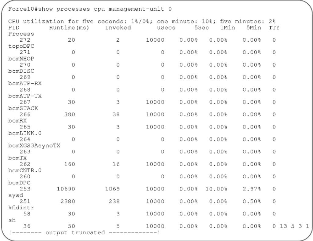
Example 3
Figure 5-38. Command Example: show processes cpu stack-unit on S-Series
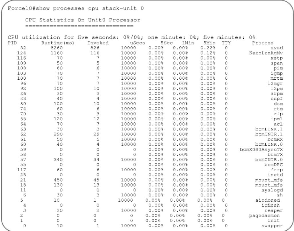
Example 4
Figure 5-39. Command Example: show processes memory on S-Series
![Force10#show processes memory Memory Statistics On Unit 0 Processor (bytes) ============================================================================================================================================================================================================================================================================================================================================----+ start Total : 160231424, MaxUsed : 130596864 [09/19/2007 03:11:17] CurrentUsed: 130596864, CurrentFree: 29634560 SharedUsed : 14261872, SharedFree : 6709672 PID Process ResSize Size Allocs Frees Max Current 124 KernLrnAgMv 140410880 0 0 0 0 0 117 frrp 5677056 217088 87650 0 87650 87650 116 xstp 7585792 1536000 551812 49692 518684 502120 109 span 5709824 221184 55386 0 55386 55386 108 pim 5869568 720896 12300 0 12300 12300 103 igmp 5513216 327680 18236 16564 18236 1672 100 mrtm 6905856 516096 72846 0 72846 72846 96 l2mgr 6107136 491520 254858 115948 172038 138910 92 l2pm 5607424 221184 667578 579740 120966 87838 86 arpm 5353472 208896 54528 16564 54528 37964 83 ospf 4210688 475136 0 0 0 0 80 dsm 6057984 552960 22838 0 22838 22838 74 rtm 6311936 577536 574792 298152 376024 276640 70 rip 5001216 249856 528 0 528 528 68 ipml 5292032 339968 67224 0 67224 67224 64 acl 5607424 544768 140086 66256 123522 73830 63 bcmLINK.1 40410880 0 0 0 0 0 62 bcmCNTR.1 140410880 0 0 0 0 61 bcmRX 140410880 0 0 0 0 60 bcmLINK.0 140410880 0 0 0 0 59 bcmXGS3AsyncTX 140410880 0 0 0 0 0 58 bcmTX 140410880 0 0 0 0 0 57 bcmCNTR.0 140410880 0 0 0 0 0 55 bcmDPC 140410880 0 0 0 0 0 52 sysd 44650496 22876160 3930856 1358248 2589172 2572608 28 inetd 876544 69632 0 0 0 0 0 "21 mount_mfs" "22642688" "1953792" " " " " " " " " " " " " " " " " " " " " " " " " " " " " " " " " " " " " " " " " " " " " " " " " " " " " " " " " " " " " " " " " " " " " " " " " " " " " " " " " " " " " " " " " " " " " " " " " " !----output truncated ----!](/content/2026/05/838261/images/c1055af7197390dbf36e57eda5bee9c3f4ef4a17aa75ccd1642033f1f68f1056.jpg)
Example 5
Figure 5-40. Command Example: show processes memory stack-unit on S-Series
| Force10#show processes memory stack-unit 0 | ||||||
| Memory Statistics On Unit 0 Processor (bytes) | ||||||
| start | ||||||
| Total : | 160231424, MaxUsed : | 130596864 [09/19/2007 03:11:17] | ||||
| CurrentUsed: | 130560000, CurrentFree: | 29671424 | ||||
| SharedUsed : | 14261872, SharedFree : | 6709672 | ||||
| PID Process | ResSize | Size | Allocs | Frees | Max | Current |
| 124 KernLrnAgMv | 140410880 | 0 | 0 | 0 | 0 | 0 |
| 117 frrp | 5677056 | 217088 | 87650 | 0 | 87650 | 87650 |
| 116 xstp | 7585792 | 1536000 | 551812 | 49692 | 518684 | 502120 |
| 109 span | 5709824 | 221184 | 55386 | 0 | 55386 | 55386 |
| 108 pim | 5869568 | 720896 | 12300 | 0 | 12300 | 12300 |
| 103 igmp | 5513216 | 327680 | 18236 | 16564 | 18236 | 1672 |
| 100 mrtm | 6905856 | 516096 | 72846 | 0 | 72846 | 72846 |
| 96 12mgr | 6107136 | 491520 | 254858 | 115948 | 172038 | 138910 |
| 92 12pm | 5607424 | 221184 | 667578 | 579740 | 120966 | 87838 |
| 86 arpm | 5353472 | 208896 | 54528 | 16564 | 54528 | 37964 |
| 83 ospf | 4210688 | 475136 | 0 | 0 | 0 | 0 |
| 80 dsm | 6057984 | 552960 | 22838 | 0 | 22838 | 22838 |
| 74 rtm | 6311936 | 577536 | 574792 | 298152 | 376024 | 276640 |
| 70 rip | 5001216 | 249856 | 528 | 0 | 528 | 528 |
| 68 ipml | 5292032 | 339968 | 67224 | 0 | 67224 | 67224 |
Related Commands
| show hardware layer2 acl Display Layer 2 ACL data for the selected stack member and stack member port-pipe. | |
| show hardware layer3 | Display Layer 3 ACL or QoS data for the selected stack member and stack member port-pipe. |
| show hardware stack-unit | Display the data plane or management plane input and output statistics of the designated component of the designated stack member. |
| show hardware system-flow | Display Layer 3 ACL or QoS data for the selected stack member and stack member port-pipe. |
| show interfaces stack-unit | Display information on all interfaces on a specific S-Series stack member. |
| show processes memory (S-Series) | Display CPU usage information based on processes running in an S-Series |
show processes ipc flow-control

Display the Single Window Protocol Queue (SWPQ) statistics.
Syntax
show processes ipc flow-control [cp | rp1 | rp2 | lp linecard-number]
Parameters
| cp | (OPTIONAL) Enter the keyword cp to view the Control Processor's SWPQ statistics. |
| rp1 | (OPTIONAL) Enter the keyword rp1 to view the Control Processor's SWPQ statistics on Route Processor 1.* |
| rp2 | (OPTIONAL) Enter the keyword rp2 to view the Control Processor's SWPQ statistics on Route Processor 2.* |
| lp linecard-number | (OPTIONAL) Enter the keyword lp followed by the line card number to view the Control Processor's SWPQ statistics on the specified line card.* |
* In the S-Series, this command supports only the cp keyword, not the rp1, rp2, and lp options. See Figure 5-45.
Defaults
No default values or behavior
Command Modes
EXEC
EXEC Privilege
Command History
Version 8.1.1.0 Introduced on E-Series ExaScale
Version 7.6.1.0 Introduced on S-Series
Version 7.5.1.0 Introduced on C-Series and E-Series
Example 1 Figure 5-41. Command Example: show processes ipc flow-control from C-Series
| Force10# show processes ipc flow-control cp | |||||||||
| Q Statistics on CP Processor | |||||||||
| TxProcess | RxProcess | Cur Len | High Mark | Time Out | Retries | Msg Sent | Ack Rcvd | Aval Retra | Max Retra |
| ACLO | RTMO | 0 | 0 | 0 | 0 | 0 | 0 | 10 | 10 |
| ACLO | DIFFSERVO | 0 | 0 | 0 | 0 | 0 | 0 | 10 | 10 |
| ACLO | IGMPO | 0 | 0 | 0 | 0 | 0 | 0 | 10 | 10 |
| ACLO | PIMO | 0 | 0 | 0 | 0 | 0 | 0 | 10 | 10 |
| ACLO | ACL20 | 0 | 1 | 0 | 0 | 2 | 2 | 50 | 50 |
| CFGO | CFGDATASYNCO | 0 | 2 | 0 | 0 | 7 | 7 | 255 | 255 |
| DHCP0 | ACLO | 0 | 1 | 0 | 0 | 9 | 9 | 25 | 25 |
| DHCP0 | IFMGRO | 0 | 0 | 0 | 0 | 0 | 0 | 25 | 25 |
| RTMO | ARPMGRO | 0 | 1 | 0 | 0 | 1 | 1 | 136 | 136 |
| ACL20 | IGMPO | 0 | 0 | 0 | 0 | 0 | 0 | 50 | 50 |
| LACP0 | IFMGRO | 0 | 2 | 0 | 0 | 4 | 4 | 25 | 25 |
| ARPMGRO | MRTMO | 0 | 0 | 0 | 0 | 0 | 0 | 100 | 100 |
| ACL20 | PIMO | 0 | 0 | 0 | 0 | 0 | 0 | 50 | 50 |
| MACMGRO | ACLO | 0 | 1 | 0 | 0 | 1 | 1 | 25 | 25 |
| TCLASSMGRO | |||||||||
Example 2 Figure 5-42. Command Example: show processes ipc flow-control rp from E-Series
| Force10# show processes ipc flow-control cp | |||||||||
| Q Statistics on CP Processor | |||||||||
| TxProcess | RxProcess | Cur Len | High Mark | Time Out | Retries | Msg Sent | Ack Rcvd | Aval Retra | Max Retra |
| DHCP0 | ACL0 | 0 | 1 | 0 | 0 | 6 | 6 | 25 | 25 |
| DHCP0 | IFMGR0 | 0 | 0 | 0 | 0 | 0 | 0 | 25 | 25 |
| IFMGR0 | FEFD0 | 0 | 3 | 0 | 0 | 27 | 27 | 8 | 8 |
| IFMGR0 | IPMGR0 | 0 | 6 | 0 | 0 | 44 | 44 | 8 | 8 |
| IFMGR0 | SNMP0 | 0 | 1 | 0 | 0 | 16 | 16 | 8 | 8 |
| IFMGR0 | SFL_CP0 | 0 | 4 | 0 | 0 | 31 | 31 | 8 | 8 |
| IFMGR0 | EVENTTERMLOGO | 0 | 1 | 0 | 0 | 6 | 6 | 8 | 8 |
| IFMGR0 | PORTMIRRO | 0 | 0 | 0 | 0 | 0 | 0 | 8 | 8 |
| IFMGR0 | DHCP0 | 0 | 1 | 0 | 0 | 6 | 6 | 8 | 8 |
| IFMGR0 | TCLASSMGRO | 0 | 2 | 0 | 0 | 13 | 13 | 8 | 8 |
| IFMGR0 | VRRP0 | 0 | 3 | 0 | 0 | 25 | 25 | 8 | 8 |
| IFMGR0 | MRTMO | 0 | 2 | 0 | 0 | 21 | 21 | 8 | 8 |
| TCLASSMGRO | ARPMGRO | 0 | 0 | 0 | 0 | 0 | 0 | 100 | 100 |
| IFMGR0 | IPMGR2 | 0 | 6 | 0 | 0 | 44 | 44 | 8 | 8 |
Table 5-4 list the definitions of the fields shown in Figure 5-41 and Figure 5-42.
Table 5-4. Description of show processes ipc flow-control cp output
| Field Description | |
| Source QID /Tx Process Source Service Identifier | |
| Destination QID/Rx Process Destination Service Identifier | |
| Cur Len Current number of messages enqueued | |
| High Mark Highest number of packets in the queue at any point of time | |
| #of to / Timeout Timeout count | |
| #of Retr /Retries Number of retransmissions | |
| #msg Sent/Msg Sent/ Number of messages sent | |
| #msg Ackd/Ack Rcvd Number of messages acknowledged | |
| Retr /Available Retra Number of retries left | |
| Total/ Max Retra Number of retries allowed | |
Example 2 Figure 5-43. Command Example: show processes ipc flow-control rp
| Force10# show processes ipc flow-control rp2 | ||||||||
| [qid] Source->Dest | Cur Len | High Mark | #of to | #of Retr | #msg Sent | #msg Ackd | Retr | total |
| [1] unknown2->unknown2 | 0 | 0 | 0 | 0 | 0 | 0 | 3 | 3 |
| [2] 12pm0->spanMgr0 | 0 | 2 | 0 | 0 | 2298 | 2298 | 25 | 25 |
| [3] fvrp0->macMgr0 | 0 | 0 | 0 | 0 | 0 | 0 | 25 | 25 |
| [4] 12pm0->fvrp0 | 0 | 2 | 0 | 0 | 1905 | 1905 | 25 | 25 |
| [5] fvrp0->12pm0 | 0 | 0 | 0 | 0 | 0 | 0 | 25 | 25 |
| [6] stp0->12pm0 | 0 | 0 | 0 | 0 | 0 | 0 | 25 | 25 |
| [7] spanMgr0->macMgr0 | 0 | 0 | 0 | 0 | 0 | 0 | 25 | 25 |
| [8] spanMgr0->ipMgr0 | 0 | 0 | 0 | 0 | 0 | 0 | 25 | 25 |
| Force10# | ||||||||
Example 3 Figure 5-44. Command Example: show processes ipc flow-control Ip
| Force10#show processes ipc flow-control lp 10 Q Statistics on LP 10 | |||||||||
| TxProcess RxProcess | Cur Len | High Mark | Time Out | Retries | Msg Sent | Ack Rcvd | Aval Retra | Max Retra | |
| ACL_AGENT10 | PIMO | 0 | 0 | 0 | 0 | 0 | 0 | 20 | 20 |
| ACL_AGENT10 | PIMO | 0 | 0 | 0 | 0 | 0 | 0 | 20 | 20 |
| FRRPAGT10 | FRRP0 | 0 | 0 | 0 | 0 | 0 | 0 | 30 | 30 |
| IFACT10 | IFMGRO | 0 | 1 | 0 | 0 | 1 | 1 | 8 | 8 |
| LPDMACAGENT10 Force10# | MACMGRO | 0 | 0 | 0 | 0 | 0 | 0 | 25 | 25 |
Example 4 Figure 5-45. Command Example: show processes ipc flow-control on S-Series
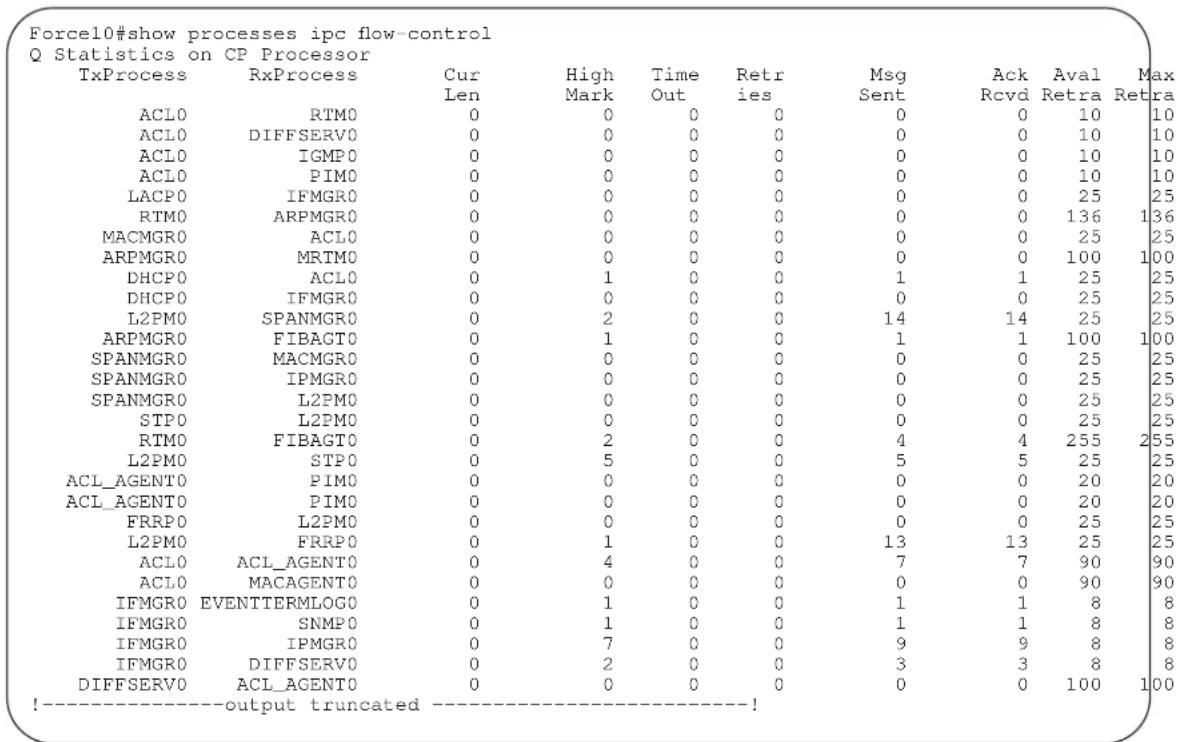
Usage Information The Single Window Protocol (SWP) provides flow control-based reliable communication between the sending and receiving software tasks.
Important Points to Remember
- A sending task enqueues messages into the SWP queue3 for a receiving task and waits for an acknowledgement.
- If no response is received within a defined period of time, the SWP timeout mechanism resubmits the message at the head of the FIFO queue.
• After retrying a defined number of times, the following timeout message is generated:
SWP-2-NOMORETIMEOUT - In the display output in Figure 5-45, a retry (Retries) value of zero indicates that the SWP mechanism reached the maximum number of retransmissions without an acknowledgement.
show processes memory (C-Series and E-Series)
C E
View memory usage information based on processes running in the system.
Syntax
show processes memory [cp | lp slot-number {lp all | lp summary} | rp1 | rp2]
Parameters
| cp | (OPTIONAL) Enter the keyword cp to view memory usage of the Control Processor. |
| lp slot-number | (OPTIONAL) Enter the keyword lp and the slot number to view information on the line-card processor in that slot.C-Series Range: 0-7E-Series Range: 0 to 13 on a E1200/E1200i, 0 to 6 on a E600/E600i, and 0 to 5 on a E300. |
| lp all | (OPTIONAL) Enter the keyword lp all to view CP memory usage on all active line cards. |
| lp summary | (OPTIONAL) Enter the keyword lp summary to view a summary of the line card CP memory usage. |
| rp1 | (OPTIONAL) Enter the keyword rp1 to view memory usage of the Route Processor 1.Note: This option is supported on the E-Series only. |
| rp2 | (OPTIONAL) Enter the keyword rp2 to view memory usage of the Route Processor 2.Note: This option is supported on the E-Series only. |
Command Modes
EXEC
EXEC Privilege
Command History
| Version 8.1.1.2 Introduced on E-Series ExaScale E600i | |
| Version 8.1.1.0 Introduced on E-Series ExaScale E1200i | |
| Version 7.5.1.0 Introduced on C-Series | |
| Version 7.4.1.0 | Added lp all and lp summary options |
| Version 6.5.1.0 | For rp1 and rp2 only, the output displays memory consumption of all the processes including a summary (see Figure 5-47 and Figure 5-48. |
Usage Information
The output for show process memory displays the memory usage statistics running on CP part (sysd) of the system. The Sysd is an aggregate task that handles all the tasks running on C-Series' and E-Series' CP.
In FTOS Release 7.4.1.0 and higher, the total counter size (for all 3 CPUs) in show memory and show processes memory will differ based on which FTOS processes are counted.
- In the show memory (C-Series and E-Series) display output, the memory size is equal to the size of the application processes.
- In the show processes memory (C-Series and E-Series) display output, the memory size is equal to the size of the application processes plus the size of the system processes.
Example
Figure 5-46. Command Example: show processes memory (partial)
| Force10#show processes memoryMemory Statistics On CP Processor (bytes) | ||||
| Total: 452689184, MaxUsed: 64886986, CurrentUsed: 64873866, CurrentTaskName TotalAllocated TotalFreed MaxHeld CurrentHolding tRootTask 39083408 1395840 38143920 37687568 tARL 64 0 64 64 tBcmTask 256 0 256 256 tPortmapd 18560 0 18560 18560 tShell 3440 0 3440 3440 tPingTmo0 0 1088 0 0 tExcTask 0 592864 0 0 tme 4002494 192 4002302 4002302 ipc 34060 192 34060 33868 irc 943436 0 943436 943436 RpmAvailMgr 9376 32 9344 9344 ev 133188 0 133188 133188 evterm 26752 0 26752 26752 evhdlr 2528 8064 2528 0 dlm 7556256 7366960 1239104 189296 dla 416 0 416 416 tsm 15136 0 15136 15136 fmg 766560 0 766560 766560 fileProc 416 0 416 416 sysAdmTsk 42028 0 42028 42028 |
Example
Figure 5-47. Command Example: show processes memory rp1
| Force10#show processes memory rpl | |||||||
| Total : 954650624, MaxUsed : 114135040 [3/8/2006 15:1:42] | |||||||
| CurrentUsed: 114135040, CurrentFree: 840515584 | |||||||
| SharedUsed : 7849096, SharedFree : 13122448 | |||||||
| PID | Process | ResSize | Size | Allocs | Frees | Max | Current |
| 124 | ospf | 3215360 | 425984 | 0 | 0 | 0 | 0 |
| 119 | dsm | 7749632 | 1859584 | 797026 | 0 | 797026 | 797026 |
| 114 | ipml | 3821568 | 229376 | 297324 | 0 | 297324 | 297324 |
| 112 | rtm | 4722688 | 421888 | 925008 | 0 | 925008 | 925008 |
| 107 | rip | 3731456 | 253952 | 198216 | 0 | 198216 | 198216 |
| 104 | acl | 4734976 | 430080 | 1127524 | 0 | 1127524 | 1127524 |
| 100 | sysdl | 11636736 | 2019328 | 965798 | 0 | 965798 | 965798 |
| 98 | sysmon | 528384 | 94208 | 0 | 0 | 0 | 0 |
| 36 | sshd | 1286144 | 430080 | 0 | 0 | 0 | 0 |
| 34 | inetd | 663552 | 98304 | 0 | 0 | 0 | 0 |
| 32 | mount_mfs | 42397696 | 2514944 | 0 | 0 | 0 | 0 |
| 19 | mount_mfs | 364544 | 2449408 | 0 | 0 | 0 | 0 |
| 6 | sh | 446464 | 737280 | 0 | 0 | 0 | 0 |
| 5 | aiodoned | 76529664 | 0 | 0 | 0 | 0 | 0 |
| 4 | ioflush | 76529664 | 0 | 0 | 0 | 0 | 0 |
| 3 | reaper | 76529664 | 0 | 0 | 0 | 0 | 0 |
| 2 | pagedaemon | 76529664 | 0 | 0 | 0 | 0 | 0 |
| 1 | init | 139264 | 2375680 | 0 | 0 | 0 | 0 |
| 0 | swapper | 76529664 | 0 | 0 | 0 | 0 | 0 |
Example Figure 5-48. Command Example: show processes memory rp2
| Force10#show processes memory rp2 | |||||||
| Total : 953700352, MaxUsed : 149417984 [3/8/2006 12:33:6] | |||||||
| CurrentUsed: 149417984, CurrentFree: 804282368 | |||||||
| SharedUsed : 7847200, SharedFree : 13124344 | |||||||
| PID | Process | ResSize | Size | Allocs | Frees | Max | Current |
| 145 | vrrp | 3870720 | 266240 | 297324 | 0 | 297324 | 297324 |
| 141 | fvrp | 4472832 | 204800 | 797010 | 0 | 797010 | 797010 |
| 138 | xstp | 10764288 | 7155712 | 367534 | 0 | 367534 | 367534 |
| 133 | span | 4136960 | 167936 | 565810 | 0 | 565810 | 565810 |
| 132 | pim | 6664192 | 516096 | 2812528 | 0 | 2812528 | 2812528 |
| 128 | igmp | 4112384 | 344064 | 627684 | 0 | 627684 | 627684 |
| 124 | ipm2 | 3923968 | 237568 | 363396 | 0 | 363396 | 363396 |
| 120 | mrtm | 25567232 | 593920 | 697790 | 0 | 697790 | 697790 |
| 116 | 12mgr | 4579328 | 520192 | 830098 | 0 | 830098 | 830098 |
| 112 | 12pm | 3874816 | 225280 | 367446 | 32948 | 367446 | 334498 |
| 108 | arpm | 3702784 | 208896 | 268420 | 0 | 268420 | 268420 |
| 104 | acl2 | 3485696 | 94208 | 132144 | 0 | 132144 | 132144 |
| 100 | sysd2 | 11657216 | 1679360 | 998834 | 0 | 998834 | 998834 |
| 98 | sysmon | 528384 | 94208 | 0 | 0 | 0 | 0 |
| 36 | sshd | 1286144 | 430080 | 0 | 0 | 0 | 0 |
| 34 | inetd | 663552 | 98304 | 0 | 0 | 0 | 0 |
| 32 | mount_mfs | 41791488 | 2514944 | 0 | 0 | 0 | 0 |
| 19 | mount_mfs | 364544 | 2449408 | 0 | 0 | 0 | 0 |
| 6 | sh | 446464 | 737280 | 0 | 0 | 0 | 0 |
| 5 | aiodoned | 76967936 | 0 | 0 | 0 | 0 | 0 |
| 4 | ioflush | 76967936 | 0 | 0 | 0 | 0 | 0 |
| 3 | reaper | 76967936 | 0 | 0 | 0 | 0 | 0 |
| 2 | pagedaemon | 76967936 | 0 | 0 | 0 | 0 | 0 |
| 1 | init | 139264 | 2375680 | 0 | 0 | 0 | 0 |
| 0 | swapper | 76967936 | 0 | 0 | 0 | 0 | 0 |
| Force10# | |||||||
Table 5-5 defines the fields that appear in the show processes memory output.
Table 5-5. Descriptions of show processes memory rp1/rp2 output
| Field Description | |
| Total: Total system memory available | |
| MaxUsed: Total maximum memory used ever (history indicated with time stamp) | |
| CurrentUsed: Total memory currently in use | |
| CurrentFree: Total system memory available | |
| SharedUsed: Total used shared memory | |
| SharedFree: Total free shared memory | |
| PID Process ID | |
| Process | Process Name |
| ResSize | Actual resident size of the process in memory |
| Size | Process test, stack, and data size |
| Allocs | Total dynamic memory allocated |
| Frees | Total dynamic memory freed |
| Max | Maximum dynamic memory allocated |
| Current | Current dynamic memory in use |
show processes memory (S-Series)
S Display memory usage information based on processes running in the S-Series system.
Syntax show processes memory {management-unit | stack unit {0-7| all | summary}}
| Parameters | management-unit | Enter the keyword management-unit for CPU memory usage of the stack management unit. |
| stack unit 0-7 | Enter the keyword stack unit followed by a stack unit ID of the member unit for which to display memory usage on the forwarding processor. | |
| all | Enter the keyword all for detailed memory usage on all stack members. | |
| summary | Enter the keyword summary for a brief summary of memory availability and usage on all stack members. | |
| hand Modes | EXEC | |
| EXEC Privilege | ||
| Command History | Version 7.7.1.0 Modified: Added management-unit option | |
| Version 7.6.1.0 Introduced on S-Series | ||
| Usage Information | The output for show process memory displays the memory usage statistics running on CP part (sysd) of the system. The Sysd is an aggregate task that handles all the tasks running on S-Series' CP.For S-Series, the output of show memory and this command will differ based on which FTOS processes are counted.In the show memory display output, the memory size is equal to the size of the application processes.In the output of this command, the memory size is equal to the size of the application processes plus the size of the system processes. | |
Example Figure 5-49. Command Example: show processes memory on S-Series
| Forcel0#show processes memory stack-unit 0 | ||||
| Total: 268435456, MaxUsed: 2420244, CurrentUsed: 2420244, CurrentFree: 266015212 | ||||
| TaskName | TotalAllocated | TotalFreed | MaxHeld | CurrentHolding |
| tme | 435406 | 397536 | 54434 | 37870 |
| ipc | 16652 | 0 | 16652 | 16652 |
| timerMgr | 33304 | 0 | 33304 | 33304 |
| sysAdmTsk | 33216 | 0 | 33216 | 33216 |
| tFib4 | 1943960 | 0 | 1943960 | 1943960 |
| aclAgent | 90770 | 16564 | 74206 | 74206 |
| ifagt_1 | 21318 | 16564 | 21318 | 4754 |
| dsagt | 6504 | 0 | 6504 | 6504 |
| MacAgent | 269778 | 0 | 269778 | 269778 |
Example Figure 5-50. Command Example: show processes memory management-unit
| Force10#show processes management-unit | |||||||
| Total : 151937024, MaxUsed : 111800320 [2/25/2008 4:18:53] | |||||||
| CurrentUsed: 98848768, CurrentFree: 53088256 | |||||||
| SharedUsed : 13007848, SharedFree : 7963696 | |||||||
| PID | Process | ResSize | Size | Allocs | Frees | Max | Current |
| 337 | KernLrnAgMv | 117927936 | 0 | 0 | 0 | 0 | 0 |
| 331 | vrrp | 5189632 | 249856 | 50572 | 0 | 50572 | 50572 |
| 323 | frrp | 5206016 | 241664 | 369238 | 0 | 369238 | 369238 |
| 322 | xstp | 7430144 | 2928640 | 38328 | 0 | 38328 | 38328 |
| 321 | pim | 5267456 | 823296 | 62168 | 0 | 62168 | 62168 |
| 314 | igmp | 4960256 | 380928 | 18588 | 16564 | 18588 | 2024 |
| 313 | mrtm | 6742016 | 1130496 | 72758 | 0 | 72758 | 72758 |
| 308 | 12mgr | 5607424 | 552960 | 735214 | 380972 | 619266 | 354242 |
| 301 | 12pm | 5001216 | 167936 | 1429522 | 1176044 | 286606 | 253478 |
| 298 | arpm | 4628480 | 217088 | 71092 | 33128 | 71092 | 37964 |
| 294 | ospf | 5468160 | 503808 | 724204 | 662560 | 78208 | 61644 |
| 288 | dsm | 6778880 | 1159168 | 39490 | 16564 | 39490 | 22926 |
| 287 | rtm | 5713920 | 602112 | 442280 | 198768 | 376024 | 243512 |
| 284 | rip | 4562944 | 258048 | 528 | 0 | 528 | 528 |
| 281 | lacp | 4673536 | 266240 | 221060 | 0 | 221060 | 221060 |
| 277 | ipml | 4837376 | 380928 | 83788 | 0 | 83788 | 83788 |
| 273 | acl | 5005312 | 512000 | 239564 | 149076 | 123616 | 90488 |
| 272 | topoDPC | 117927936 | 0 | 0 | 0 | 0 | 0 |
| 271 | bcmNHOP | 117927936 | 0 | 0 | 0 | 0 | 0 |
| 270 | bcmDISC | 117927936 | 0 | 0 | 0 | 0 | 0 |
| 269 | bcmATP-RX | 117927936 | 0 | 0 | 0 | 0 | 0 |
| 268 | bcmATP-TX | 117927936 | 0 | 0 | 0 | 0 | 0 |
| 267 | bcmSTACK | 117927936 | 0 | 0 | 0 | 0 | 0 |
| 266 | bcmRX | 117927936 | 0 | 0 | 0 | 0 | 0 |
| 265 | bcmLINK.0 | 117927936 | 0 | 0 | 0 | 0 | 0 |
Table 5-6 defines the fields that appear in the show processes memory output.
Table 5-6. Descriptions of show processes memory output
| Field Description | |
| Total: Total system memory available | |
| MaxUsed: Total maximum memory used ever (history indicated with time stamp) | |
| CurrentUsed: Total memory currently in use | |
| CurrentFree: Total system memory available | |
| SharedUsed: Total used shared memory | |
| SharedFree: Total free shared memory | |
| PID | Process ID |
| Process | Process Name |
| ResSize | Actual resident size of the process in memory |
| Size | Process test, stack, and data size |
| Allocs | Total dynamic memory allocated |
| Frees | Total dynamic memory freed |
| Max | Maximum dynamic memory allocated |
| Current | Current dynamic memory in use |
show processes switch-utilization

Show switch fabric utilization.
Syntax
show processes switch-utilization
Command Mode
EXEC
EXEC Privilege
Command History
Version 8.1.1.0 Introduced on E-Series ExaScale
E-Series original Command
Example
Figure 5-51. Command Example: show processes switch-utilization
| Force10#show processes switch-utilization | |||
| Switch fabric utilization | 5Sec | 1Min | 5Min |
| 3% | 3% | 3% | |
Usage Information
An asterisk (*) in the output indicates a legacy card that is not support by the show processes switch-utilization command.
show rpm

Show the current RPM status.
Syntax
show rpm [number [brief] | all]
Parameters
| number | (OPTIONAL) Enter either zero (0) or 1 for the RPM. |
| all | (OPTIONAL) Enter the keyword all to view a table with information on all present RPMs. |
| brief | (OPTIONAL) Enter the keyword brief to view an abbreviated list of RPM information. |
Command Modes
EXEC
EXEC Privilege
Command History
Version 8.1.1.0 Introduced on E-Series ExaScale
Version 7.5.1.0 Introduced on C-Series
E-Series original Command
E-Series Example
Figure 5-52. Command Example: show rpm on E-Series
Forcel0#show RPM 0
-- RPM card 0 --
Status : active
Next Boot : online
Card Type : RPM - Route Processor Module (LC-EF-RPM)
Hardware Rev : 2.0
Num Ports : 1
Up Time : 36 min, 51 sec
Last Restart : reset
FTOS Version : 6.2.1.0
Jumbo Capable : yes
CP Boot Flash : A: 2.4.0.6    B: 2.4.0.7 [booted]
RP1 Boot Flash: A: 2.4.0.7 [booted]    B: 2.4.0.5
RP2 Boot Flash: A: 2.4.0.7 [booted]    B: 2.4.0.5
CP Mem Size : 536870912 bytes
RP1 Mem Size : 0 bytes
RP2 Mem Size : 0 bytes
Temperature : 49C
Power Status : PEM0: absent or down    PEM1: up
Voltage : ok
Serial Number : 0016788
Part Number : 7520013800 Rev 01
Vendor Id : 01
Date Code : 06182004
Country Code : 01
Forcel0#
Table 5-7 defines the fields displayed in Figure 5-52.
Table 5-7. Descriptions of show rpm output
| Field Description | |
| Status Displays the RPM's status. | |
| Next Boot Displays whether the | RPM is to be brought online at the next system reload. |
| Card Type Displays the RPM catalog number. | |
| Hardware Rev Displays theE-Series chipset hardware revision level: 1.0 (non-Jumbo); 1.5 (Jumbo-enabled); 2.0 (or above is TeraScale). | |
| Num Ports Displays the number of active ports. | |
| Up Time Displays the number of hours and minutes since the RPM's last reboot. | |
| Last Restart States the reason for the last RPM reboot.C-Series possible values:“normal power-cycle” (reset power-cyclecommand)“reset by master” (peer RPM reset by master RPM)“over temperature shutdown”“power supply failed”E-Series possible values:“normal power-cycle” (insufficient power, normal power cycle)“reset by user” (automatic failover, software reload of both RPMs, or master RPM resetting peer)“force-failover” (redundancy force-failovercommand) | |
| FTOS Version Displays the operating software version. | |
| Jumbo Capable Displays a Yes or No indicating if the RPM is capable of sending and receiving Jumbo frames.This field does not indicate if the chassis is in Jumbo mode; for that determination, use theshow chassis briefcommand. | |
Table 5-7. Descriptions of show rpm output
| Field | Description |
| CP Boot Flash Displays the two | possible Boot Flash versions for the Control Processor. The [Booted] keyword next to the version states which version was used at system boot. |
| RP1 Boot Flash Displays the two | possible Boot Flash versions for the Routing Processor 1. The [Booted] keyword next to the version states which version was used at system boot. |
| RP2 Boot Flash Displays the two | possible Boot Flash versions for the Routing Processor 2. The [Booted] keyword next to the version states which version was used at system boot. |
| CP Mem Size Displays the memory of the Control Processor. | |
| RP1 Mem Size Displays the memory of the Routing Processor 1. | |
| PR2 Mem Size Displays the memory of the Routing Processor 2. | |
| Temperature Displays the temperature of the RPM.Minor alarm status if temperature is over 65^ C. | |
| Power Status Lists the status of the power modules in the chassis. | |
| Voltage Displays the power rails for the line card. | |
| Serial Num Displays the line card serial number. | |
| Part Num Displays the line card part number. | |
| Vendor ID Displays an internal code, which specifies the manufacturing vendor. | |
| Date Code Displays the line card's manufacturing date. | |
| Country Code | Displays the country of origin. 01 = USA |
Related Commands
| show chassis | View information on all elements of the system. |
| show linecard | View information on a line card. |
| show sfm | View information on the SFM. |
show software ifm

Display interface management (IFM) data.
Syntax
show software ifm {clients [summary] | ifagt number | ifcb interface | stack-unit unit-ID | trace-flags}
Parameters
| clients | Enter the keyword clients to display IFM client information. |
| summary | (OPTIONAL) Enter the keyword summary to display brief information about IFM clients. |
| ifagt number | Enter the keyword ifagt followed by the number of an interface agent to display software pipe and IPC statistics. |
| ifcbinterface | Enter the keyword ifcb followed by one of the following interface IDs followed by the slot/port information to display interface control block information for that interface:For a 1-Gigabit Ethernet interface, enter the keyword GigabitEthernet.For a Port Channel interface, enter the keyword port-channel followed by a number:C-Series and S-Series Range: 1-128E-Series Range: 1 to 32 for EtherScale, 1 to 255 for TeraScale and 1 to 512 for ExaScale.For a 10G Ethernet interface, enter the keyword TenGigabitEthernet.C-Series options also include:fastethernet for a Fast Ethernet interfaceloopback for a Loopback interfacemanagementethernet for a Management Ethernet interfacenull for a Null interfacevlan for a VLAN interface (Range: 1 to 4094, 1 to 2094 for ExaScale) | |
| stack-unitunit-ID | Enter the keyword stack-unit followed by the stack member number to display IFM information for that unit.Range: 0 to 1Note: This option is only available on S-Series. | |
| trace-flags | Enter the keyword trace-flags to display IFM information for internal trace flags. | |
| Defaults | None | |
| Command Mode | EXEC | |
| EXEC Privilege | ||
| Command History | Version 7.6.1.0 Introduced for C-Series and S-Series | |
S-Series Example
Figure 5-53. Command Example: show software ifm clients summary on S-Series
| Force10#show software ifm clients summary | |||||
| ClntType | Inst | svcMask | subSvcMask | tlvSvcMask | tlvSubSvc swp |
| IPM | 0 | 0x00000000 | 0x00000000 | 0x90ff71f3 | 0x021e0e81 31 |
| RTM | 0 | 0x00000000 | 0x00000000 | 0x800010ff | 0x01930000 43 |
| VRRP | 0 | 0x00000000 | 0x00000000 | 0x803330f3 | 0x00400000 39 |
| L2PM | 0 | 0x00000000 | 0x00000000 | 0x87ff79ff | 0x0e032200 45 |
| ACL | 0 | 0x00000000 | 0x00000000 | 0x867f50c3 | 0x000f0218 44 |
| OSPF | 0 | 0x00000dfa | 0x00400098 | 0x00000000 | 0x00000000 0 |
| PIM | 0 | 0x000000f3 | 0x00030000 | 0x00000000 | 0x00000000 0 |
| IGMP | 0 | 0x000e027f | 0x00000000 | 0x00000000 | 0x00000000 0 |
| SNMP | 0 | 0x00000000 | 0x00000000 | 0x800302c0 | 0x00000002 30 |
| EVITTERM | 0 | 0x00000000 | 0x00000000 | 0x800002c0 | 0x00000000 29 |
| MRTM | 0 | 0x00000000 | 0x00000200 | 0x81f7103f | 0x00000000 38 |
| DSM | 0 | 0x00000000 | 0x00000000 | 0x80771003 | 0x00000000 32 |
| LACP | 0 | 0x00000000 | 0x00000000 | 0x8000383f | 0x00000000 35 |
| DHCP | 0 | 0x00000000 | 0x00000000 | 0x800000c2 | 0x0000c000 37 |
| V6RAD | 0 | 0x00000433 | 0x00030000 | 0x00000000 | 0x00000000 0 |
| Unidentified Client0 | 0x006e0002 | 0x00000000 | 0x00000000 | 0x00000000 0 | |
show switch links

View the switch fabric backplane or internal status.
Syntax
show switch links {backplane | internal}
Parameters
| backplane | Enter the keyword backplane to view a table with information on the link status of the switch fabric backplane for both SFMs. |
| internal | Enter the keyword internal to view a table with information on the internal status of the switch fabric modules. |
Defaults
None
Command Modes
EXEC
Command History
Version 7.5.1.0 Introduced on C-Series
Example
Figure 5-54. Command Example: show switch links backplane
| Force10# show switch links backplane | |||||||
| Switch fabric backplane link status: | |||||||
| LC SlotID Port7 | Port0 | SFM0 Links Status | SFM1 Links Status | ||||
| Port1 | Port2 | Port3 | Port4 | Port5 | Port6 | ||
| 0 | up | up | up | up | down | down | down |
| 1 | not present | ||||||
| 2 | not present | ||||||
| 3 | not present | ||||||
| 4 | not present | ||||||
| 5 | not present | ||||||
| 6 | up | up | up | up | down | down | down |
| 7 | not present | ||||||
| up - Both ends of the link are up | |||||||
| down - Both ends of the link are down | |||||||
| up / down - SFM side up and LC side down | |||||||
| down / up - SFM side down and LC side up | |||||||
| Force10# | |||||||
show system (S-Series)
S Display the current status of all stack members or a specific member.
Syntax
show system [brief | stack-unit unit-id]
Parameters
| brief | (OPTIONAL) Enter the keyword brief to view an abbreviated list of system information. |
| stack-unit unit-id | (OPTIONAL) Enter the keyword stack-unit followed by the stack member ID for information on that stack member. Range: 0 to 7. |
Command Modes
EXEC
EXEC Privilege
Command History
Version 7.8.1.0 Modified output: Boot Flash field will display code level for boot code 2.8.1.1 and newer, while older boot codes are displayed as "Present".
Version 7.7.1.0 Modified output: Added Master Priority field.
Version 7.6.1.0 Introduced for S-Series switches
Usage
Figure 5-55 shows the output from the show system brief command.
Figure 5-56 shows the output from the show system stack-unit command.
Example
Figure 5-55. Command Example: show system brief
| Force10#show system brief | |||||||
| Stack MAC : 0:1:e8:d6:4:70 | |||||||
| -- Stack Info -- | |||||||
| Unit | UnitType | Status | ReqTyp | CurTyp | Version | Ports | |
| 0 | Member | not present | |||||
| 1 | Standby | online | S50V | S50V | 7.7.1.0 | 52 | |
| 2 | Mgmt | online | S50V | S50V | 7.7.1.0 | 52 | |
| 3 | Member | not present | |||||
| 4 | Member | not present | |||||
| 5 | Member | not present | |||||
| 6 | Member | not present | |||||
| 7 | Member | not present | |||||
| -- Module Info -- | |||||||
| Unit | Module No | Status | Module Type | Ports | |||
| 1 | 0 | online | S50-01-10GE-2P | 2 | |||
| 1 | 1 | online | S50-01-24G-2S | 1 | |||
| 2 | 0 | online | S50-01-10GE-2P | 2 | |||
| 2 | 1 | online | S50-01-24G-2S | 1 | |||
| -- Power Supplies -- | |||||||
| Unit | Bay Status Type | ||||||
| 1 | 0 up AC | ||||||
| 1 | 1 absent AC | ||||||
| 2 | 0 up AC | ||||||
| 2 | 1 absent AC | ||||||
| -- Fan Status -- | |||||||
| Unit | TrayStatus Fan0 Fan1 Fan2 Fan3 Fan4 Fan5 | ||||||
| 1 | up up up up up up up up up up up up up up up up up up up up up up up up up up up up up up up up up up up up up up up up up up up up up up up up up up up up up up up up up up up up up up up up up up up up up up up up up up up up up up up up up up up up up up up up up up up up up up up up up up up up up Up Up Up Up Up Up Up Up Up Up Up Up Up Up Up Up Up Up Up Up Up Up Up Up Up Up Up Up Up Up Up Up Up Up Up Up Up Up Up Up Up Up Up Up Up Up Up Up Up Up Up Up Up Up Up Up Up Up Up Up Up Up Up Up Up Up Up Up Up Up Up Up Up Up Up Up Up Up Up Up Up Up Up Up Up Up Up Up Up Up Up Up Up Up Up Up Up Up Up UpUpUpUpUpUpUpUpUpUpUpUpUpUpUpUpUpUpUpUpUpUpUpUpUpUpUpUpUpUpUpUpUpUpUpUpUpUpUpUpUpUpUpUpUpUpUpUpUpUpUpUpUpUpUpUpUpUpUpUpUpUpUpUpUpUpUpUpUpUpUpUpUpUpUpUpUpUpUpUpUpUpUpUpUpUpUpUpUpUpUpUpUpUpUpUpUpUpUpUpUpUmpupupupupupupupupupupupupupupupupupupupupupupupupupupupupupupupupupupupupupupupupupupupupupupupupupupupupupupupupupupupupupupupupupupupupupupupupupupupupupupupupupupupupupupupupupupupupupup Umpupupunaputpumaputpumaputpumaputpumaputpumaputpumaputpumaputpumaputpumaputpumaputpumaputpumaputpumaputpumaputpumaputpumaputpumaputpumaputpumaputpumaputpumaputpumaputpumaputpumaputpumaputpunaputpumaputpumaputpumaputpumaputpumaputpumaputpumaputpumaputpumaputpumaputpumaputpumaputpumaputpumaputpumaputpumaputpumaputpumaputpumaputpumaputpumaputpumaputpumaputpumaput pumaput pumaput pumaput pumaput pumaput pumaput pumaput pumaput pumaput pumaput pumaput pumaput pumaput pumaput pumaput pumaput pumaput pumaput pumaput pumaput pumaput pumaput pumaput pumaput pumaput uniput uniput uniput uniput uniput uniput uniput uniput uniput uniput uniput uniput uniput uniput uniput uniput uniput uniput uniput uniput uniput uniput uniput uniput uniput uniput uniput uniput uniput uniput uniput uniput uniput unipuit unipuit unipuit unipuit unipuit unipuit unipuit unipuit unipuit unipuit unipuit unipuit unipuit unipuit unipuit unipuit unipuit unipuit unipuit unipuit unipuit unipuit unipuit unipuit unipuit unipuit unipuit unipuit unipuit unipuit unipuit unipuit unipuit unipuit unsununununununununununununununununununununununununununununununununununununununununununununununununununununununununununununununununununununununununununununununununununununununununununununununununununununinonononononononononononononononononononononononononononononononononononononononononononononononononononononononononononononononononononononononononononononononononononononononononononononononononononon onanlonlonlonlonlonlonlonlonlonlonlonlonlonlonlonlonlonlonlonlonlonlonlonlonlonlonlonlonlonlonlonlonlonlonlonlonlonlonlonlonlonlonlonlonlonlonlonlonlonlonlonlonlonlonlonlonlonlonlonlonlonlonlonlonlonlonlonlonlonlonlonlonlonlonlonlonlonlonlonlonlonlonlonlonlonlonlonlonlonlonlonlonlonlonlonlonlonlonlonlonLonOnOnOnOnOnOnOnOnOnOnOnOnOnOnOnOnOnOnOnOnOnOnOnOnOnOnOnOnOnOnOnOnOnOnOnOnOnOnOnOnOnOnOnOnOnOnOnOnOnOnOnOnOnOnOnOnOnOnOnOnOnOnOnOnOnOnOnOnOnOnOnOnOnOnOnOnOnOnOnOnOnOnOnOnOnOnOnOnOnOnOnOnOnOnOnOnOnOnOnOnOmpuntUnopuntUnopuntUnopuntUnopuntUnopuntUnopuntUnopuntUnopuntUnopuntUnopuntUnopuntUnopuntUnopuntUnopuntUnopuntUnopuntUnopuntUnopuntUnopuntUnopuntUnopuntUnopuntUnopuntUnopuntUnopuntUnopuntUnopuntUnopuntUnopuntUnopuntUnopuntUnopuntUnopuntUnopUnterapeantuontereantuontereantuontereantuontereantuontereantuontereantuontereantuontereantuontereantuontereantuontereantuontereantuontereantuontereantuontereantuontereantuontereantuontereantuontereantuontereantuontereantuontereantuontereantuontereantuontereantuonteresetuonteresetuonteresetuonteresetuonteresetuonteresetuonteresetuonteresetuonteresetuonteresetuonteresetuonteresetuonteresetuonteresetuonteresetuonteresetuonteresetuonteresetuonteresetuonteresetuonteresetuonteresetuonteresetuonteresetuonteresetuonteressett uontereset uontereset uontereset uontereset uontereset uontereset uontereset uontereset uontereset uontereset uontereset uontereset uontereset uontereset uontereset uontereset uontereset uontereset uontereset uontereset uontereset uontereset uontereset uontereset uontereset uontereseset uontereset uontereset uontereset uontereset uontereset uontereset uontereset uontereset uontereset uontereset uontereset uontereset uontereset uontereset uontereset uontereset uontereset uontereset uontereset uontereset uontereset uontereset uontereset uontereset uontresetsuPontsusususususususususususususususususususususususususususususususususususususususususususususususususususususususususususususususususususususususususususususususususususususes | ||||||
Example
Figure 5-56. Command Example: show system stack-unit
| Force10#show system stack-unit 0 | |||||||
| -- Unit 0 -- | |||||||
| Unit Type : Management Unit | |||||||
| Status : online | |||||||
| Next Boot : online | |||||||
| Required Type : S50V - 48-port E/FE/GE with POE (SB) | |||||||
| Current Type : S50V - 48-port E/FE/GE with POE (SB) | |||||||
| Master Priority : 4 | |||||||
| Hardware Rev : 2.0 | |||||||
| Num Ports : 52 | |||||||
| Up Time : 3 hr, 17 min | |||||||
| FTOS Version : 7.6.1.0a | |||||||
| Jumbo Capable : yes | |||||||
| POE Capable : no | |||||||
| Boot Flash : Present | |||||||
| Memory Size : 254701568 bytes | |||||||
| Temperature : 43C | |||||||
| Voltage : ok | |||||||
| Serial Number : DZ267160000 | |||||||
| Part Number : 7590003600 Rev B | |||||||
| Vendor Id : 07 | |||||||
| Date Code : 12172007 | |||||||
| Country Code : 01 | |||||||
| Burned In MAC : 00:01:e8:cc:cc:cc | |||||||
| No Of MACs : 3 | |||||||
| --Module 0-- | |||||||
| Status : online | |||||||
| Module Type : S50-01-10GE-2P - 2-port 10GE XFP (SB) | |||||||
| Num Ports : 2 | |||||||
| Hot Pluggable : no | |||||||
| -- Module 1 - | |||||||
| Status : online | |||||||
| Module Type : S50-01-10GE-2C - 2-port 10GE CX4 (SB) | |||||||
| Num Ports : 2 | |||||||
| Hot Pluggable : no | |||||||
| - Power Supplies -- | |||||||
| Unit Bay Status Type | |||||||
| 0 0 up AC 0 1 absent -- Fan Status -- Unit TrayStatus Fan0 Fan1 Fan2 Fan3 Fan4 Fan5 0 up up up up up force10# | |||||||
Related Commands
show version Display the FTOS version.
| show processes memory (S-Series) | Display memory usage based on running processes. |
| show system stack-ports | Display information about the stack ports on all switches in the S-Series stack. |
| show hardware stack-unit | Display the data plane and management plane input and output statistics of a particular stack member. |
| stack-unit priority Configure the ability of an S-Series switch to become the management unit of a stack. | |
show tech-support (C-Series and E-Series)

Display, or save to a file, a collection of data from other show commands, the information necessary for Dell Force10 technical support to perform troubleshooting.
Syntax
show tech-support [linecard 0-6 | page] | {display | except | find | grep | no-more | save}
Parameters
| linecard 0-6 | (OPTIONAL) Enter the keyword linecard followed by the linecard number to view information relating to a specific linecard. |
| page | (OPTIONAL) Enter the keyword page to view 24 lines of text at a time.Press the SPACE BAR to view the next 24 lines.Press the ENTER key to view the next line of text. |
| display, except, find, grep, no-more | If you use the pipe command ( | ), then enter one of these keywords to filter command output. Refer to Chapter 2, CLI Basics for details on filtering commands. |
| save | Enter the save keyword (following the pipe) to save the command output.flash: Save to local flash drive (flash://filename (max 20 chars) )slot0: Save to local file system (slot0://filename (max 20 chars) ) |
Command Modes
EXEC Privilege
Command History
| Version 7.8.1.0 | Introduced save to file options |
| Version 7.5.1.0 | Introduced on C-Series |
| Version 6.5.4.0 | Show clock included in display on E-Series |
C-Series Example
Figure 5-57. Command Example: show tech-support (partial) on C-Series
| Force10#show tech-support page | |
| —— show version ——————— | |
| Force10 Networks Real Time Operating System Software | |
| Force10 Operating System Version: 1.0 | |
| Force10 Application Software Version: FTOS 7.5.1.0 | |
| Copyright (c) 1999-2007 by Force10 Networks, Inc. | |
| Build Time: Tue Sep 12 15:39:17 IST 2006 | |
| Build Path: /sites/maa/work/sw//C-SERIES/SW/SRC | |
| Force10 uptime is 18 minutes | |
| System image file is "/work/sw/IMAGES/Chassis/C300-ODC-2/FTOS-CS.bin" | |
| Chassis Type: C300 | |
| Control Processor: IBM PowerPC 750FX (Rev D2.2) with 1073741824 bytes of memory. 128K bytes of non-volatile configuration memory. | |
| 1 Route Processor/Switch Fabric Module 2 48-port GE 10/100/1000Base-T line card with RJ45 interface (CB) 1 FastEthernet/IEEE 802.3 interface(s) 96 GigabitEthernet/IEEE 802.3 interface(s) | |
| —— show HA information ——————— | |
| -- RPM Status ——— | |
| RPM Slot ID: 0 RPM Redundancy Role: Primary RPM State: Active RPM SW Version: CS-1-1-317 Link to Peer: Down Peer RPM: not present | |
| -- RPM Redundancy Configuration ——— | |
| Primary RPM: rpm0 Auto Data Sync: Full Failover Type: Hot Failover Auto reboot RPM: Disabled Auto failover limit: 3 times in 60 minutes | |
| ...more—— |
E-Series Example
Figure 5-58. Command Example: show tech-support save (partial) on E-Series
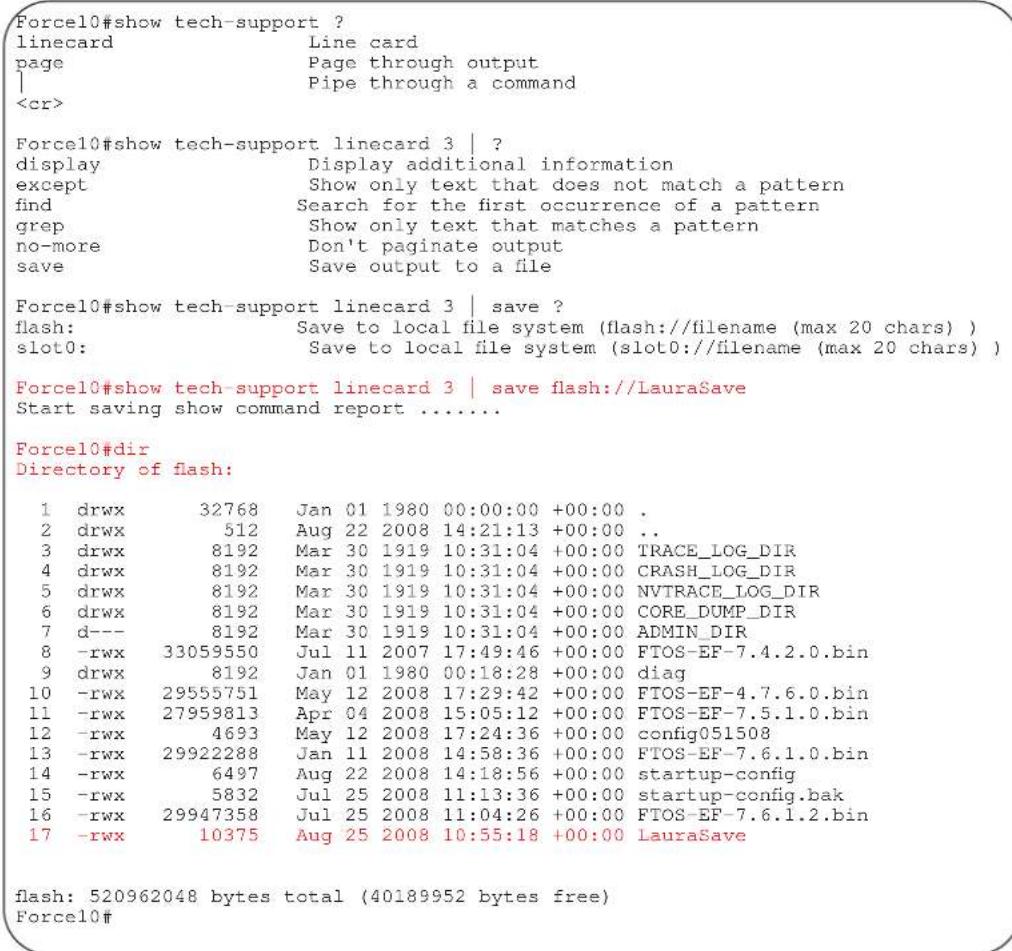
Usage Information
Without the linecard or page option, the command output is continuous, use CTRL-Z to interrupt the command output.
The save option works with other filtering commands. This allows you to save specific information of a show command. The save entry should always be the last option.
For example: Force10#show tech-support | grep regular-expression | except regular-expression | find regular-expression | save flash://result
This display output is an accumulation of the same information that is displayed when you execute one of the following show commands:
• show cam-profile
• show cam-ipv4flow
• show chassis
• show clock
• show environment
• show file-system
• show interface
• show inventory
• show ip management-route
• show ip protocols
• show ip route summary
• show processes cpu
• show processes memory
• show redundancy
• show rpm
• show running-conf
• show sfm
• show version
Related Commands
| show version Display the FTOS version. | |
| show linecard Display the line card(s) status. | |
| show environment (C-Series and E-Series) | Display system component status. |
| show processes memory (C-Series and E-Series) | Display memory usage based on running processes. |
show tech-support (S-Series)
S Display a collection of data from other show commands, necessary for Dell Force10technical support to perform troubleshooting on S-Series switches.
Syntax show tech-support [stack-unit unit-id | page]
| Parameters | stack-unit | (OPTIONAL) Enter the keyword stack-unit to view CPU memory usage for the stack member designated by unit-id. Range: 0 to 7 |
| page | (OPTIONAL) Enter the keyword page to view 24 lines of text at a time.Press the SPACE BAR to view the next 24 lines.Press the ENTER key to view the next line of text. | |
| When using the pipe command (| ), enter one of these keywords to filter command output.Refer to Chapter 2, CLI Basics for details on filtering commands. | ||
| save | Enter the save keyword to save the command output.flash: Save to local flash drive (flash://filename (max 20 chars)) |
Command Modes EXEC Privilege
Command History
| Version 7.8.1.0 Introduced save to file options |
| Version 7.6.1.0 Expanded to support S-Series switches |
S-Series Examples
Figure 5-59. Command Example: show tech-support save (partial) on S-Series
Force10#show tech-support ?
page Page through output
stack-unit Unit Number
| Pipe through a command
<cr>
Force10#show tech-support stack-unit 1 ?
| Pipe through a command
<cr>
Force10#show tech-support stack-unit 1 | ?
except Show only text that does not match a pattern
find Search for the first occurrence of a pattern
grep Show only text that matches a pattern
no-more Don't paginate output
save Save output to a file

Force10#show tech-support stack-unit 1 | save ?
flash: Save to local file system (flash://filename (max 20 chars) )

Force10#show tech-support stack-unit 1 | save flash://LauraSave
Start saving show command report ......
Force10#
Force10#dir
Directory of flash:

1 drw- 16384 Jan 01 1980 00:00:00 +00:00 .
2 drwx 1536 Jul 13 1996 02:38:06 +00:00 ..
3 d--- 512 Nov 20 2007 15:46:44 +00:00 ADMIN_DIR
4 -rw- 7124 Jul 13 1996 02:33:04 +00:00 startup-config
5 -rw- 3303 Feb 14 2008 22:01:16 +00:00 startup-config.oldChassis
6 -rw- 6561 May 17 1996 04:10:54 +00:00 startup-config.bak
7 -rw- 6539 May 29 1996 10:35:42 +00:00 test.cfg
8 -rw- 276 Jul 15 1996 23:11:14 +00:00 LauraSave

flash: 3104256 bytes total (3072512 bytes free)
Force10#
Figure 5-60. Command Example: show tech-support (partial) on S-Series
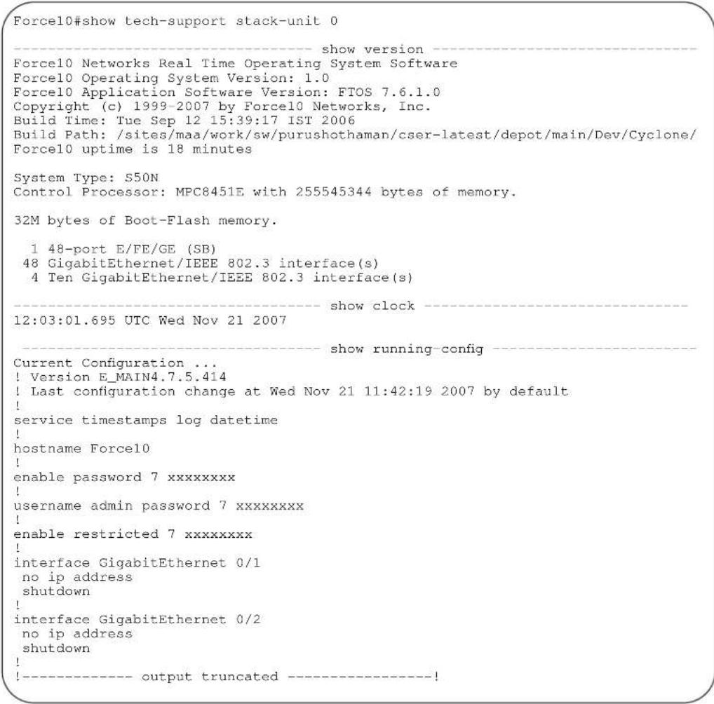
Usage Information
Without the page or stack-unit option, the command output is continuous, use Ctrl-z to interrupt the command output.
The save option works with other filtering commands. This allows you to save specific information of a show command. The save entry should always be the last option.
For example: Force10#show tech-support | grep regular-expression | except regular-expression | find regular-expression | save flash://result
This display output is an accumulation of the same information that is displayed when you execute one of the following show commands:
• show cam
• show clock
• show environment
• show file
• show interfaces
• show inventory
| Related Commands | show ip protocolsshow ip route summaryshow processes cpushow processes memoryshow redundancyshow running-confshow version |
| show version Display the FTOS version. | |
| show system (S-Series) Display the current switch status. | |
| show environment (S-Series) Display system component status. | |
| show processes memory (S-Series) Display memory usage based on running processes. |
ssh-peer-rpm
| C E | Open an SSH connection to the peer RPM. | |
| Syntax | ssh-peer-rpm [-I username] | |
| Parameters | -I username (OPTIONAL) Enter the keyword -I followed by your user name.Default: The user name associated with the terminal | |
| Defaults | Not configured. | |
| Command Modes | EXEC | |
| EXEC Privilege | ||
| Command History | Version 8.1.1.0 Introduced on E-Series ExaScale | |
| Version 7.5.1.0 Introduced on C-Series | ||
| Version 6.3.1.0 Introduced on E-Series | ||
| Usage Information | This command is not available when the peer RPMs are running different FTOS releases. | |
telnet | Connect through Telnet to a server. The Telnet client and server in FTOS support IPv4 and IPv6 connections. You can establish a Telnet session directly to the router, or a connection can be initiated from the router. | |
| Syntax | telnet {host|ip-address|ipv6-address prefix-length|vrf vrf instance name} [/source-interface] | |
telnet
Parameters
| host | Enter the name of a server. |
| ip-address | Enter the IPv4 address in dotted decimal format of the server. |
| ipv6-address prefix-length | Enter the IPv6 address in the X:X:X:X::X format followed by the prefix length in the /x format.Range: /0 to /128Note:The :: notation specifies successive hexadecimal fields of zeros |
| vrf instance | (Optional) E-Series Only: Enter the keyword vrf followed by the VRF Instance name. |
| source-interface | (OPTIONAL) Enter the keywords /source-interface followed by the interface information to include the interface's IP address.Enter the following keywords and slot/port or number information:For a 100/1000 Ethernet interface, enter the keyword GigabitEthernet followed by the slot/port information.For a 1-Gigabit Ethernet interface, enter the keyword GigabitEthernet followed by the slot/port information.For a Loopback interface, enter the keyword loopback followed by a number from zero (0) to 16383.For the Null interface, enter the keyword null followed by 0.For a Port Channel interface, enter the keyword port-channel followed by a number:C-Series and S-Series Range: 1-128E-Series Range: 1 to 32 for EtherScale, 1 to 255 for TeraScale and 1 to 512 for ExaScale.For SONET interface types, enter the keyword sonet followed by the slot/port information.For a 10-Gigabit Ethernet interface, enter the keyword TenGigabitEthernet followed by the slot/port information.For a VLAN interface, enter the keyword vlan followed by a number from 1 to 4094. |
Defaults
Not configured.
Command Modes
EXEC
EXEC Privilege
Command History
Version 8.2.1.0 Introduced on E-Series ExaScale (IPv6) Increased number of VLANs on ExaScale to 4094 (was 2094)
Version 8.1.1.0 Introduced on E-Series ExaScale (IPv4)
Version 7.9.1.0 Introduced VRF.
Version 7.6.1.0 Introduced on S-Series
Version 7.5.1.0 Introduced on C-Series and added support for IPv6 address on E-Series only
Usage Information
Telnet to link-local addresses is not supported.
telnet-peer-rpm

Open a Telnet connection to the peer RPM.
Syntax
telnet-peer-rpm
Defaults
Not configured.
Command Modes
EXEC
EXEC Privilege
Command History
Version 8.1.1.0 Introduced on E-Series ExaScale
Version 7.5.1.0 Introduced on C-Series
Version 6.2.1.1 Introduced on E-Series
Usage Information
Opening a telnet connection from the Standby RPM to an Active RPM follows the authentication procedure configured in the chassis. However, opening a telnet connection from the Active RPM into the Standby RPM requires local authentication.
Configuring an ACL on a VTY line will block a Telnet session using the telnet-peer-rpm command in the standby to active RPM direction only. Such an ACL will not block an internal Telnet session in the active RPM to standby RPM direction.
terminal length

Configure the number of lines displayed on the terminal screen.
Syntax
terminal length screen-length
To return to the default values, enter terminal no length.
Parameters
| screen-length | Enter a number of lines. Entering zero will cause the terminal to display without pausing.Range: 0 to 512.Default: 24 lines. |
Defaults
24 lines
Command Modes
EXEC
EXEC Privilege
Command History
| Version 8.1.1.0 Introduced on E-Series ExaScale |
| Version 7.6.1.0 Introduced on S-Series |
| Version 7.5.1.0 Introduced on C-Series |
| E-Series original Command |
terminal xml

Enable XML mode in Telnet and SSH client sessions.
Syntax
terminal xml
To exit the XML mode, enter terminal no xml.
Defaults
Disabled
Command Modes
EXEC
EXEC Privilege
Command History
| Version 8.1.1.0 Introduced on E-Series ExaScale |
| Version 7.7.1.0 Introduced on C-Series |
| Version 6.5.1.0 Introduced for E-Series |
Usage Information
This command enables the XML input mode where you can either cut and paste XML requests or enter the XML requests line-by-line. For more information on using the XML feature, refer to the XML chapter in the FTOS Configuration Guide.
traceroute

View a packet's path to a specific device.
Syntax
traceroute {host | vrf instance | ip-address | ipv6-address}
Parameters
| host | Enter the name of device. |
| vrf instance | (Optional) E-Series Only: Enter the keyword vrf followed by the VRF Instance name. |
| ip-address | Enter the IP address of the device in dotted decimal format. |
| ipv6-address | Enter the IPv6 address, in the X:X:X:X::X format, to which you are testing connectivity.Note: The :: notation specifies successive hexadecimal fields of zeros |
Defaults
Timeout = 5 seconds; Probe count = 3; 30 hops max; 40 byte packet size; UDP port = 33434
Command Modes
EXEC
EXEC Privilege
Command History
| Version 8.4.1.0 IPv6 trace routing available on management interface. |
| Version 8.2.1.0 Introduced on E-Series ExaScale with IPv6 |
| Version 8.1.1.0 Introduced on E-Series ExaScale (IPv4 only) |
| Version 7.9.1.0 Introduced VRF. |
| Version 7.6.1.0 Added support for S-Series |
| Version 7.5.1.0 Introduced on C-Series |
| Version 7.4.1.0 Added support for IPv6 address on E-Series |
| E-Series original Command |
Usage Information
When you enter the traceroute command without specifying an IP address (Extended Traceroute), you are prompted for a target and source IP address, timeout in seconds (default is 5), a probe count (default is 3), minimum TTL (default is 1), maximum TTL (default is 30), and port number (default is 33434). To keep the default setting for those parameters, press the ENTER key.
For the source IP address option, you may enter IPv6 global addresses only (link-local addresses are not supported).
For IPv6, you are prompted for a minimum hop count (default is 1) and a maximum hop count (default is 64).
Example
Figure 5-61. Command Example: traceroute (IPv4)
![Force10#traceroute www.force10networks.com Translating "www.force10networks.com"...domain server (10.11.0.1) [OK] Type Ctrl-C to abort. Tracing the route to www.force10networks.com (10.11.84.18), 30 hops max, 40 byte packets TTL Hostname Probel Probe2 Probe3 1 10.11.199.190 001.000 ms 001.000 ms 002.000 ms 2 gwegress-sjc-02.force10networks.com (10.11.30.126) 005.000 ms 001.000 ms 001.000 ms 3 fw-sjc-01.force10networks.com (10.11.127.254) 000.000 ms 000.000 ms 000.000 ms 4 www.force10networks.com (10.11.84.18) 000.000 ms 000.000 ms 000.000 ms Force10#](/content/2026/05/838261/images/8fe33d52fa671452d7046b716ff1270432a57ca0e1ad921ddac4da4bcaaafff2.jpg)
Figure 5-62 contains examples of the IPv6 traceroute command with both a compressed IPv6 address and uncompressed address.
Example
Figure 5-62. Command Example: traceroute (IPv6)
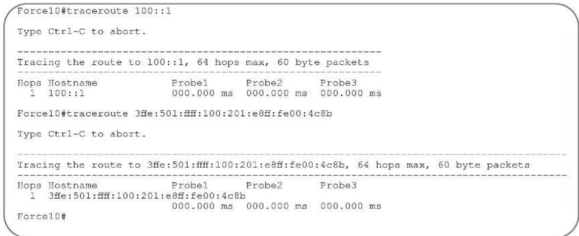
Related Commands
ping Test connectivity to a device.
undebug all

Disable all debug operations on the system.
Syntax undebug all
Defaults No default behavior or values
Command Modes EXEC Privilege
Command History
Version 8.1.1.0 Introduced on E-Series ExaScale
Version 7.6.1.0 Introduced on S-Series
Version 7.5.1.0 Introduced on C-Series
E-Series original Command
upload trace-log
C E Upload trace log files from the three CPUs (cp, rp1, and rp2)
Syntax upload trace-log {cp {cmd-history | hw-trace | sw-trace}| rp1 {cmd-history | hw-trace | sw-trace}| rp2 {cmd-history | hw-trace | sw-trace}}
Parameters
| cp | rp1 | rp2 | Enter the keyword cp | rp1 | rp2 to upload the trace log from that CPU. |
| cmd-history | (OPTIONAL) Enter the keyword cmd-history to upload the CPU’s command history. |
| hw-trace | (OPTIONAL) Enter the keyword hw-trace to upload the CPU’s hardware trace. |
| sw-trace | (OPTIONAL) Enter the keyword sw-trace to upload the CPU’s software trace. |
Defaults No default behavior or values
Command Modes EXEC
EXEC
EXEC Privilege
Command History
Version 8.1.1.0 Introduced on E-Series ExaScale
Version 7.5.1.0 Introduced on C-Series and expanded to support command history, hardware trace, and software trace logs
Version 6.1.1.0 Introduced on E-Series
Usage Information The log information is uploaded to flash:/TRACE_LOG_DIR
virtual-ip

Configure a virtual IP address for the active management interface. Virtual addresses can be configured both for IPv4 and IPv6 independently.
Syntax
virtual-ip {ipv4-address | ipv6-address}
| Parameters | {ipv4-address | ipv6-address} | Enter the IPv4 address (A.B.C.D) or IPv6 address (X:X:X:X::) of the active management interface. |
Defaults
No default behavior or values
| Command Modes | CONFIGURATION |
| Command History | Version 8.4.1.0 Added support for IPv6 addressing. |
| Version 8.1.1.0 Introduced on E-Series ExaScale | |
| Version 7.5.1.0 Introduced on C-Series | |
| E-Series original Command |
Usage Both IPv4 and IPv6 virtual address can be configured simultaneously, but only one of each. Each time this command is issued it will replace the previously configured address of the same family, IPv4 or IPv6. The no virtual-ip command now takes an address/prefix-length argument, so that the desired address only is removed. If no virtual-ip is entered without any specified address, then both IPv4 and IPv6 virtual addresses are removed.
Example
Figure 5-63. Command Example: virtual ip (IPv4 and IPv6)
| Force10#virtual-ip 10.11.197.99/16 |
| Force10#virtual-ip fdaa:bbbb:cccc:1004::60/64 |
write

Copy the current configuration to either the startup-configuration file or the terminal.
Syntax
write {memory | terminal}
| Parameters | memory | Enter the keywordmemoryto copy the current running configuration to the startup configuration file. This command is similar to thecopy running-configstartup-configcommand. |
| terminal | Enter the keywordterminalto copy the current running configuration to the terminal. This command is similar to theshow running-configcommand. |
| Command Modes | EXEC Privilege |
| Command History | Version 8.1.1.0 Introduced on E-Series ExaScale |
| Version 7.6.1.0 Introduced on S-Series | |
| Version 7.5.1.0 Introduced on C-Series | |
| E-Series original Command |
Related Commands
save
Save configurations created in BOOT_USER mode (BLI).
Usage Information
The write memory command saves the running-configuration to the file labeled startup-configuration. When using a LOCAL CONFIG FILE other than the startup-config not named “startup-configuration” (for example, you used a specific file during the boot config command) the running-config is not saved to that file; use the copy command to save any running-configuration changes to that local file.
802.1ag
Overview
802.1ag is available only on platform: S
Commands
This chapter contains the following commands:
- ccm disable
- ccm transmit-interval
- clear ethernet cfm traceroute-cache
- database hold-time
- disable
- domain
- ethernet cfm
- ethernet cfm mep
- ethernet cfm mip
- mep cross-check
- mep cross-check enable
- mep cross-check start-delay
- ping ethernet
• show ethernet cfm domain
• show ethernet cfm maintenance-points local
• show ethernet cfm maintenance-points remote
• show ethernet cfm mipbd
• show ethernet cfm statistics
• show ethernet cfm port-statistics
• show ethernet cfm traceroute-cache - service
- traceroute cache hold-time
- traceroute cache size
- traceroute ethernet
ccm disable
| S | Disable CCM. |
| Syntax | ccm disable |
| Enter no ccm disable to enable CCM. | |
| Defaults | Disabled |
| Command Modes | ECFM DOMAIN |
| Command History | Version 8.3.7.0 Introduced on the S4810. |
| Version 8.3.1.0 Introduced on S-Series |
ccm transmit-interval
| S | Configure the transmit interval (mandatory). The interval specified applies to all MEPs in the domain. | |
| Syntax | ccm transmit-interval seconds | |
| Parameters | seconds | Enter a transmit interval.Range: 1,10,60,600 |
| Defaults | 10 seconds | |
| Command Modes | ECFM DOMAIN | |
| Command History | Version 8.3.7.0 Introduced on the S4810. | |
| Version 8.3.1.0 Introduced on S-Series | ||
clear ethernet cfm traceroute-cache
| S Delete all Link Trace Cache entries. | |
| Syntax clear ethernet cfm traceroute-cache | |
| Defaults | None |
| Command Modes | EXEC Privilege |
| Command History | Version 8.3.7.0 Introduced on the S4810. |
| Version 8.3.1.0 Introduced on S-Series | |
database hold-time
Set the amount of time that data from a missing MEP is kept in the Continuity Check Database.
| Syntax | database hold-time minutes | |
| Parameters | minutes | Enter a hold-time.Range: 100-65535 minutes |
| Defaults | 100 minutes | |
| Command Modes | ECFM DOMAIN | |
| Command History | Version 8.3.7.0 Introduced on the S4810. | |
| Version 8.3.1.0 Introduced on S-Series | ||
disable
S Disable Ethernet CFM without stopping the CFM process.
Syntax disable
Defaults Disabled
Command Modes ETHERNET CFM
| Command History | Version 8.3.7.0 Introduced on the S4810. |
| Version 8.3.1.0 Introduced on S-Series |
domain
S Create maintenance domain.
Syntax domain name md-level number
| Parameters | name | Name the maintenance domain. |
| md-level number | Enter a maintenance domain level.Range: 0-7 | |
| Defaults | None | |
| mand Modes | ETHERNET CFM | |
| Command History | Version 8.3.7.0 Introduced on the S4810. | |
| Version 8.3.1.0 Introduced on S-Series | ||
ethernet cfm
Spawn the CFM process. No CFM configuration is allowed until the CFM process is spawned.
| Syntax | ethernet cfm |
| Defaults | Disabled |
| Command Modes | CONFIGURATION |
| Command History | Version 8.3.7.0 Introduced on the S4810. |
| Version 8.3.1.0 Introduced on S-Series |
ethernet cfm mep
S
Create an MEP.
Syntax
ethernet cfm mep {up-mep | down-mep} domain {name | level} ma-name name mepid mep-id
Parameters
| [up-mep | down-mep] | Specify whether the MEP is up or down facing.Up-MEP: monitors the forwarding path internal to an bridge on the customer or provider edge; on Dell Force10 systems the internal forwarding path is effectively the switch fabric and forwarding engine.Down-MEP: monitors the forwarding path external another bridge. |
| domain [name| level] | Enter this keyword followed by the domain name or domain level. |
| ma-name name | Enter this keyword followed by the name of the maintenance association. |
| mepid mep-id | Enter an MEP ID.Range: 1-8191 |
Defaults
None
Command Modes
INTERFACE
Command History
Version 8.3.7.0 Introduced on the S4810. Version 8.3.1.0 Introduced on S-Series
ethernet cfm mip
S
Create an MIP.
Syntax
ethernet cfm mip domain {name|level} ma-name name
Parameters
| domain [name|level] | Enter this keyword followed by the domain name or domain level. |
| ma-name name | Enter this keyword followed by the name of the maintenance association. |
Defaults
None
Command Modes
INTERFACE
Command History
Version 8.3.7.0 Introduced on the S4810.
Version 8.3.1.0 Introduced on S-Series
mep cross-check
S Enable cross-checking for an MEP.
Syntax mep cross-check mep-id
| Parameters | mep-id | Enter the MEP IDRange: 1-8191 |
| Defaults | None | |
| Hand Modes | ECFM DOMAIN | |
| Command History | Version 8.3.7.0 Introduced on the S4810. | |
| Version 8.3.1.0 Introduced on S-Series | ||
mep cross-check enable
S Enable cross-checking.
Syntax mep cross-check enable {port | vlan-id}
| Parameters | port | Down service with no VLAN association. |
| vlan-id | Enter the VLAN to apply the cross-check. | |
| Defaults | None | |
| mand Modes | ECFM DOMAIN | |
| Command History | Version 8.3.7.0 Introduced on the S4810. | |
| Version 8.3.1.0 Introduced on S-Series | ||
mep cross-check start-delay
S Configure the amount of time the system waits for a remote MEP to come up before the cross-check operation is started.
Syntax mep cross-check start-delay number
| Parameters | start-delay number | Enter a start-delay in seconds. Range: 3-100 seconds |
Defaults 3 ccms
Command Modes ETHERNET CFM
Command History
Version 8.3.7.0 Introduced on the S4810.
Version 8.3.1.0 Introduced on S-Series
ping ethernet
S Send a Loopback message.
| Syntax | ping ethernet domain [name 1 level] ma-name m a-name remote {dest-mep-id | mac-addr mac-address} source {src-mep-id | port interface} | |
| Parameters | name| level | Enter the domain name or level. |
| ma-name ma-name | Enter the keyword followed by the maintenance association name. | |
| dest-mep-id | Enter the MEP ID that will be the target of the ping. | |
| mac-addr mac-address | Enter the keyword followed by the MAC address that will be the target of the ping. | |
| src-mep-id | Enter the MEP ID that will originate the ping. | |
| port interface | Enter the keyword followed by the interface that will originate the ping. | |
| Defaults | None | |
| Command Modes | EXEC Privilege | |
| Command History | Version 8.3.7.0 Introduced on the S4810. | |
| Version 8.3.1.0 Introduced on S-Series | ||
show ethernet cfm domain
S Display maintenance domain information.
| Syntax | show ethernet cfm domain [name | level | brief] | |
| Parameters | name | level | Enter the maintenance domain |
| brief | Enter this keyword to display a | |
| Defaults | None | |
| Command Modes | EXEC Privilege | |
| Command History | Version 8.3.7.0 Introduced on the S4810. | |
| Version 8.3.1.0 Introduced on S-Series | ||
Example
Force10# show ethernet cfm domain
Domain Name: customer
Level: 7
Total Service: 1
Services
MA-Name VLAN CC-Int X-CHK Status
My_MA 200 10s enabled
Domain Name: My_Domain
Level: 6
Total Service: 1
Services
MA-Name VLAN CC-Int X-CHK Status
Your_MA 100 10s enabled
show ethernet cfm maintenance-points local

Display configured MEPs and MIPs.
Syntax
show ethernet cfm maintenance-points local [mep | mip]
Parameters
| mep | Enter this keyword to display configured MEPs. |
| mip | Enter this keyword to display configured MIPs. |
Defaults
None
Command Modes
EXEC Privilege
Command
History
Version 8.3.7.0 Introduced on the S4810.
Version 8.3.1.0 Introduced on S-Series
Example
Force10#show ethernet cfm maintenance-points local mip
| MPID | Domain Name MA Name | Level VLAN | Type Dir | Port MAC | CCM-Status |
| 0 | service1 My_MA | 4 3333 | MIP DOWN | Gi 0/5 00:01:e8:0b:c6:36 | Disabled |
| 0 | service1 Your_MA | 4 3333 | MIP UP | Gi 0/5 00:01:e8:0b:c6:36 | Disabled |
show ethernet cfm maintenance-points remote

Display the MEP Database.
Syntax
show ethernet cfm maintenance-points remote detail [active | domain {level|name} | expired | waiting]
Parameters
| active | Enter this keyword to display only the MEPs in active state. |
| domain [name | level] | Enter this keyword followed by the domain name or domain level. |
| expired | Enter this keyword to view MEP entries that have expired due to connectivity failure. | |
| waiting | Enter this keyword to display MEP entries waiting for response. | |
| Defaults | None | |
| Command Modes | EXEC Privilege | |
| Command History | Version 8.3.7.0 Introduced on the S4810. | |
| Version 8.3.1.0 Introduced on S-Series | ||
| Example | Force10#show ethernet cfm maintenance-points remote detail | |
| MAC Address: 00:01:e8:58:68:78Domain Name: cfm0MA Name: test0Level: 7VLAN: 10MP ID: 900Sender Chassis ID: Force10MEP Interface status: UpMEP Port status: ForwardingReceive RDI: FALSEMP Status: Active | ||
show ethernet cfm mipbd
⑤ Display the MIP Database.
Syntax show ethernet cfm mipdb
Defaults None
Command Modes EXEC Privilege
Command History
Version 8.3.7.0 Introduced on the S4810.
Version 8.3.1.0 Introduced on S-Series
show ethernet cfm statistics
⑤ Display MEP statistics.
Syntax show ethernet cfm statistics [domain {name / level} vlan-id vlan-id mpid mpid]
Parameters
| domain | Enter this keyword to display statistics for a particular domain. |
| name | level | Enter the domain name or level. |
| vlan-id vlan-id | Enter this keyword followed by a VLAN ID. |
| mpid mpid | Enter this keyword followed by a maintenance point ID. |
Defaults None
Command Modes EXEC Privilege
| Command History | Version 8.3.7.0 Introduced on the S4810. | |||
| Version 8.3.1.0 Introduced on S-Series | ||||
| Example | Forcel0#show ethernet cfm statistics | |||
| Domain Name: Customer | ||||
| Domain Level: 7 | ||||
| MA Name: My_MA | ||||
| MPID: 300 | ||||
| CCMs: | ||||
| Transmitted: | 1503 | RcvdSeqErrors: | 0 | |
| LTRs: | ||||
| Unexpected Rcvd: | 0 | |||
| LBRs: | ||||
| Received: | 0 | Rcvd Out Of Order: | 0 | |
| Received Bad MSDU: | 0 | |||
| Transmitted: | 0 | |||
show ethernet cfm port-statistics
§ Display CFM statistics by port.
Syntax show ethernet cfm port-statistics [interface type slot/port]
| Parameters | interface type | Enter this keyword followed by the interface type. |
| slot/port | Enter the slot and port numbers for the port. | |
| Defaults | None | |
| Command Modes | EXEC Privilege | |
| Command History | Version 8.3.7.0 Introduced on the S4810. | |
| Version 8.3.1.0 Introduced on S-Series | ||
| Example | Force10#show ethernet cfm port-statistics interface gigabitethernet 0/5Port statistics for port: Gi 0/5================ | |
| RX Statistics================ | ||
| Total CFM Pkts 75394 CCM Pkts 75394LBM Pkts 0 LTM Pkts 0LBR Pkts 0 LTR Pkts 0Bad CFM Pkts 0 CFM Pkts Discarded 0CFM Pkts forwarded 102417 | ||
| TX Statistics================ | ||
| Total CFM Pkts 10303 CCM Pkts 0LBM Pkts 0 LTM Pkts 3LBR Pkts 0 LTR Pkts 0 | ||
show ethernet cfm traceroute-cache
S Display the Link Trace Cache.
Syntax show ethernet cfm traceroute-cache
Defaults None
Command Modes EXEC Privilege
Command History
Version 8.3.7.0 Introduced on the S4810.
Version 8.3.1.0 Introduced on S-Series
Example
Force10#show ethernet cfm traceroute-cache
Traceroute to 00:01:e8:52:4a:f8 on Domain Customer2, Level 7, MA name Test2 with VLAN 2
| Hops | Host Next Host | IngressMAC Egress MAC | Ingr Action Egress Action | Relay Action FWD Status |
| 4 | 00:00:00:01:e8:53:4a:f800:00:00:01:e8:52:4a:f8 | 00:01:e8:52:4a:f8 | IngOK | RlyHitTerminal MEP |
service
S Create maintenance association.
Syntax service name vlan vlan-id
Parameters
| name | Enter a maintenance association name. |
| vlan vlan-id | Enter this keyword followed by the VLAN ID.Range: 1-4094 |
Defaults None
Command Modes ECFM DOMAIN
Command History
Version 8.3.7.0 Introduced on the S4810.
Version 8.3.1.0 Introduced on S-Series
traceroute cache hold-time
Set the amount of time a trace result is cached.
Syntax traceroute cache hold-time minutes
Parameters
| minutes | Enter a hold-time. |
| Range: 10-65535 minutes |
Defaults 100 minutes
Command Modes ETHERNET CFM
Command History
Version 8.3.7.0 Introduced on the S4810.
Version 8.3.1.0 Introduced on S-Series
traceroute cache size

Set the size of the Link Trace Cache.
Syntax
traceroute cache size entries
Parameters
entries
Enter the number of entries the Link Trace Cache can hold.
Range: 1 - 4095 entries
Defaults
100 entries
Command Modes
ETHERNET CFM
Command History
Version 8.3.7.0 Introduced on the S4810.
Version 8.3.1.0 Introduced on S-Series
traceroute ethernet

Send a Linktrace message to an MEP.
Syntax
traceroute ethernet domain [name | level] ma-name ma-name remote {mep-id mep-id | mac-addr mac-address}
Parameters
domain name | level
Enter the keyword followed by the domain name or level.
ma-name ma-name
Enter the keyword followed by the maintenance association name.
mepid mep-id
Enter the MEP ID that will be the trace target.
mac-addr mac-address
Enter the MAC address of the trace target.
Defaults
None
Command Modes
EXEC Privilege
Command History
Version 8.3.7.0 Introduced on the S4810.
Version 8.3.1.0 Introduced on S-Series
802.3ah
Overview
802.3ah is available only on platform: S
Commands
This chapter contains the following commands:
• clear ethernet oam statistics
- ethernet oam (enable/disable)
- ethernet oam (parameters)
- ethernet oam event-log size
- ethernet oam link-monitor frame
- ethernet oam link-monitor frame-seconds
- ethernet oam link-monitor high-threshold action
- ethernet oam link-monitor on
- ethernet oam link-monitor supported
- ethernet oam link-monitor symbol-period
- ethernet oam mode
- ethernet oam remote-failure
- ethernet oam remote-loopback
- ethernet oam remote-loopback (interface)
- ethernet oam timeout
• show ethernet oam discovery
• show ethernet oam status
• show ethernet oam statistics
• show ethernet oam summary
clear ethernet oam statistics

Clear Link Layer OAM statistics.
Syntax clear ethernet oam statistics interface interface
| Parameters | interface | Enter the interface for which you want to clear statistics, for example gig 0/1. |
| Parameters | None | |
| Defaults | None | |
| Command Mode | EXEC Privilege | |
| Command History | Version 8.4.1.0 Introduced on S-Series | |
ethernet oam (enable/disable)

Enable Ethernet OAM.

ethernet oam

None

Disabled

INTERFACE
Version 8.4.1.0 Introduced on S-Series
ethernet oam (parameters)

Specify a the maximum or minimum number of OAMPDUs to be sent per second.

ethernet oam {max-rate value | min-rate value}

max-rate value |
Enter a maximum or minimum rate in OAMPDU/second.
min-rate value
Range: 1-10

10

INTERFACE
Version 8.4.1.0 Introduced on S-Series
ethernet oam event-log size
S Specify the size of the event log.
Syntax ethernet oam event-log size entries
| Parameters | entries | Enter the number of entries for the log size. Range: 0 to 200. Default: 50. |
| Defaults | 50 | |
| mand Mode | CONFIGURATION | |
| Command History | Version 8.4.1.0 Introduced on S-Series | |
ethernet oam link-monitor frame
S Set the frame error thresholds and window.
Syntax ethernet oam link-monitor frame threshold {high {frames | none} | low frames | window frames}
| Parameters | high {frames | none} | Specify the high threshold value for frame errors, or disable the high threshold.Range: 1-65535Default: None |
| low frames | Specify the low threshold for frame errors.Range: 0-65535Default: 1 | |
| window frames | Specify the time period for frame errors per millisecond condition.Range: 10-600 millisecondsDefault: 100 milliseconds | |
| Defaults | As above | |
| mand Mode | INTERFACE | |
| Command History | Version 8.4.1.0 Introduced on S-Series | |
ethernet oam link-monitor frame-seconds
Set the frame-error seconds per time period thresholds and window.
Syntax ethernet oam link-monitor frame-seconds threshold {high {milliseconds | none} | low milliseconds | window milliseconds}
| Parameters | high {milliseconds | none} | Specify the high threshold value for frame error seconds per time period, or disable the high threshold. Range: 1-900 Default: None |
| low milliseconds | Specify the low threshold for frame error seconds per time period. Range: 1-900 Default: 1 | |
| window milliseconds | Specify the time period for error second per time period condition. Range: 100-900, in multiples of 100 Default: 1000 milliseconds | |
| Defaults | As above | |
| Command Mode | INTERFACE | |
| Command History | Version 8.4.1.0 Introduced on S-Series | |
ethernet oam link-monitor high-threshold action
S Disable an interface when the high threshold is exceeded for any of the monitored error conditions.
Syntax ethernet oam link-monitor high-threshold action error-disable-interface
| Defaults | Enabled |
| Command Mode | INTERFACE |
| Command History | Version 8.4.1.0 Introduced on S-Series |
ethernet oam link-monitor on
Start link performance monitoring on an interface. To stop link monitoring, enter the no ethernet oam link-monitor on command.
Link monitoring is started on an interface by default when you enable Ethernet OAM with the ethernet oam command.
Syntax ethernet oam link-monitor on
| Defaults | Enabled |
| Command Mode | INTERFACE |
| Command History | Version 8.4.1.0 Introduced on S-Series |
ethernet oam link-monitor supported
S Enable support for link performance monitoring on an interface. To disable support for link monitoring, enter the no ethernet oam link-monitor supported command.
Support for link monitoring is enabled on an interface by default when you enable Ethernet OAM with the ethernet oam command.
Syntax ethernet oam link-monitor supported
| Defaults | Enabled |
| Command Mode | INTERFACE |
| Command History | Version 8.4.1.0 Introduced on S-Series |
ethernet oam link-monitor symbol-period
S Set the symbol error thresholds and window.
Syntax ethernet oam link-monitor symbol-period threshold {high {symbols | none} | low symbols | window symbols}
| Parameters | high {symbols | none} | Specify the high threshold value for symbol errors, or disable the high threshold. Range: 1-65535 Default: None |
| low symbols | Specify the low threshold for symbol errors. Range: 0-65535 Default: 10 | |
| window symbols | Specify the time period for symbol errors per second condition. Range: 1-65535 (times 1,000,000 symbols) Default: 10 (10,000,000 symbols) | |
| Defaults | As above | |
| Command Mode | INTERFACE | |
| Command History | Version 8.4.1.0 Introduced on S-Series | |
ethernet oam mode
S Set the transmission mode to active or passive.
Syntax ethernet oam mode {active | passive}
| Parameters | active | passive | Choose either active or passive mode for the interface. |
Defaults
Active
Command Mode
INTERFACE
Command History
Version 8.4.1.0 Introduced on S-Series
ethernet oam remote-failure
S
Block or disable an interface when a particular critical link event occurs.
Syntax
ethernet oam remote-failure {critical-event | dying-gasp | link-fault} action {error-block-interface | error-disable-interface}
Parameters
critical-event
An unspecified critical event occurred.
dying-gasp An unrecoverable local failure condition occurred.
link-fault A fault occurred in the receive direction of the local peer.
error-block-interface Block the interface if the specified fault occurs.
error-disable-interface Disable the interface if the specified fault occurs.
Defaults
Disabled
Command Mode
INTERFACE
Command History
Version 8.4.1.0 Introduced on S-Series
ethernet oam remote-loopback
S
Start or stop loopback operation on a local interface with a remote peer.
Syntax
ethernet oam remote-loopback {start | stop} interface interface
Parameters
start | stop
Start or stop a loopback operation with a remote peer.
interface interface
Specify the interface on which remote-loopback starts/stops, for example gigabitethernet 0/1.
Defaults
Enabled
Command Mode
EXEC Privilege
Command History
Version 8.4.1.0 Introduced on S-Series
ethernet oam remote-loopback (interface)
S Enable support for OAM loopback on an interface and configure a timeout value.
Syntax ethernet oam remote-loopback {supported | timeout seconds}
| Parameters | supported Start or stop a loopback operation on a peer. | |
| timeout seconds | Specify the number of seconds that the local peer waits to receive a returned frame before considering a remote peer to be non-operational. Valid values are from 1 to 10. | |
| Defaults | None | |
| mand Mode | INTERFACE | |
| Command History | Version 8.4.1.0 Introduced on S-Series | |
ethernet oam timeout
Specify the amount of time that the system waits to receive an OAMPDU from a peer before considering it non-operational.
Syntax ethernet oam timeout value
| Parameters | value | Enter a timeout value in seconds. Range: 2-30 seconds |
| Defaults | 5 seconds | |
| mand Mode | INTERFACE | |
| Command History | Version 8.4.1.0 Introduced on S-Series | |
show ethernet oam discovery
S Display the OAM discovery status.
Syntax show ethernet oam discovery interface interface
| Parameters | interface | Enter the interface for which you want to display status, for example gig 0/1. |
| Defaults | None | |
| mand Mode | EXEC Privilege | |
| Command History | Version 8.4.1.0 Introduced on S-Series | |
Example
Force10# show ethernet oam discovery interface
Local client
Administrative configurations:
Mode:active
Unidirection:not supported
Link monitor:supported (on)
Remote loopback:not supported
MIB retrieval:not supported
Mtu size:1500
Operational status:
Port status:operational
Loopback status:no loopback
PDU permission:any
PDU revision:1
Remote client
MAC address:0030.88fe.87de
Vendor(OUI):0x00 0x00 0x0C
Administrative configurations:
Mode:active
Unidirection:not supported
Link monitor:supported
Remote loopback:not supported
MIB retrieval:not supported
Mtu size:1500
show ethernet oam statistics
S Display Link Layer OAM statistics per interface.
Syntax show ethernet oam statistics interface interface
Parameters
| interface | Enter the interface for which you want to display statistics, for example gig 0/1. |
Defaults
None
Command Mode
EXEC Privilege
Command History
Version 8.4.1.0 Introduced on S-Series
Example
Force10# show ethernet oam statistics interface
Counters:
Information OAMPDU Tx: 3439489
Information OAMPDU Rx: 9489
Unique Event Notification OAMPDU Tx: 0
Unique Event Notification OAMPDU x: 0
Duplicate Event Notification OAMPDU Tx: 0
Duplicate Event Notification OAMPDU Rx: 0
Loopback Control OAMPDU Tx: 0
Loopback Control OAMPDU Rx: 2
Variable Request OAMPDU Tx: 0
Variable Request OAMPDU Rx: 0
Variable Response OAMPDU Tx: 0
Variable Response OAMPDU Rx: 0
Force10 OAMPDU Tx:: 10
Force10 OAMPDU Rx:: 21
Unsupported OAMPDU Tx:: 0
Unsupported OAMPDU Rx:0
0 Link Fault Records
0 Dying Gasp Records
Total dying Gasps:: 2
Time Stamp: 00:40:23
Total dying Gasps:: 1
Time Stamp: 00:41:23
0 Critical Event Records
Remote Faults:
0 Link Fault Records
0 Dying Gasp Records
0 Critical Event Records
Local Event Logs:
0 Errored Symbol Period Records
0 Errored Frame Records
0 Errored Frame Period Records
0 Errored Frame Second Records
Remote Event Logs:
0 Errored Symbol Period Records
0 Errored Frame Records
0 Errored Frame Period Records
0 Errored Frame Second Records
show ethernet oam status
S Display Link Layer OAM status per interface.
Syntax show ethernet oam status interface interface
| Parameters | interface Enter the interface for which you want to display status, for example gig 0/1. |
| Defaults | None |
| Command Mode | EXEC Privilege |
| Command History | Version 8.4.1.0 Introduced on S-Series |
| Example | Force10# show ethernet oam status interface |
| Output Format : | |
| General | |
| Mode:active | |
| PDU max rate:10 packets per second | |
| PDU min rate:1 packet per second | |
| Link timeout:5 seconds | |
| High threshold action:no action | |
| Link Monitoring | |
| Status supported (on) | |
| Symbol Period Error | |
| Window:1 million symbols | |
| Low threshold:1 error symbol(s) | |
| High threshold:none | |
| Frame Error | |
| Window:1 million symbols | |
| Low threshold:1 error symbol(s) | |
| High threshold:none | |
| Frame Period Error | |
| Window:1 x 100,000 frames | |
| Low threshold:1 error symbol(s) | |
| High threshold:none | |
| Frame Seconds Error | |
| Window:600 x 100 milliseconds | |
| Low threshold:1 error second(s) | |
| High threshold:none |
show ethernet oam summary
S Display Link Layer OAM sessions.
Syntax show ethernet oam summary
Defaults None
Command Mode EXEC Privilege
Command History
Version 8.4.1.0 Introduced on S-Series
Example
Force10# show ethernet oam summary
Output format :
Symbols:* - Master Loopback State, # - Slave Loopback State Capability codes:L - Link Monitor, R - Remote Loopback U - Unidirection,V - Variable Retrieval
LocalRemote InterfaceMAC AddressOUIModeCapability Gi6/1/10023.84ac.b8000000DactiveL R
802.1X
The 802.1X Port Authentication commands are:
- debug dot1x
- dot1x auth-type mab-only
- dot1x authentication (Interface)
- dot1x auth-fail-vlan
- dot1x auth-server
- dot1x guest-vlan
- dot1x host-mode
- dot1x mac-auth-bypass
- dot1x max-eap-req
- dot1x max-supplicants
- dot1x port-control
- dot1x quiet-period
- dot1x reauthentication
- dot1x reauth-max
- dot1x server-timeout
- dot1x supplicant-timeout
- dot1x tx-period
• show dot1x cos-mapping interface
• show dot1x interface
An authentication server must authenticate a client connected to an 802.1X switch port. Until the authentication, only EAPOL (Extensible Authentication Protocol over LAN) traffic is allowed through the port to which a client is connected. Once authentication is successful, normal traffic passes through the port.
FTOS supports RADIUS and Active Directory environments using 802.1X Port Authentication.
Important Points to Remember
FTOS limits network access for certain users by using VLAN assignments. 802.1X with VLAN assignment has these characteristics when configured on the switch and the RADIUS server.
- 802.1X is supported on C-Series, E-Series, and S-Series.
- 802.1X is not supported on the LAG or the channel members of a LAG.
- If no VLAN is supplied by the RADIUS server or if 802.1X authorization is disabled, the port is configured in its access VLAN after successful authentication.
- If 802.1X authorization is enabled but the VLAN information from the RADIUS server is not valid, the port returns to the unauthorized state and remains in the configured access VLAN. This prevents ports from appearing unexpectedly in an inappropriate VLAN due to a configuration error. Configuration errors create an entry in Syslog.
- If 802.1X authorization is enabled and all information from the RADIUS server is valid, the port is placed in the specified VLAN after authentication.
- If port security is enabled on an 802.1X port with VLAN assignment, the port is placed in the RADIUS server assigned VLAN.
- If 802.1X is disabled on the port, it is returned to the configured access VLAN.
- When the port is in the force authorized, force unauthorized, or shutdown state, it is placed in the configured access VLAN.
- If an 802.1X port is authenticated and put in the RADIUS server assigned VLAN, any change to the port access VLAN configuration will not take effect.
- The 802.1X with VLAN assignment feature is not supported on trunk ports, dynamic ports, or with dynamic-access port assignment through a VLAN membership.
debug dot1x

Display 802.1X debugging information.
Syntax
debug dot1x [all | errors | packets | state-machine] [interface interface]
| Parameters | all | Enable all 802.1X debug messages. |
| errors | Display information about all 802.1X errors. | |
| packets | Display information about all 802.1X packets. | |
| state-machine | Display information about all 802.1X packets. | |
| interface interface | Restricts the debugging information to an interface. | |
| Defaults | Disabled | |
| mand Modes | EXEC Privilege | |
| Command History | Version 8.4.1.0 Introduced on C-Series and S-Series | |
dot1x auth-type mab-only
| C S | Use only the host MAC address to authenticate a device with MAC authentication bypass (MAB). |
| Syntax | dot1x auth-type mab-only |
| Defaults | Disabled |
| Command Modes | INTERFACE |
| Command History | Version 8.4.2.1 Introduced on the C-Series and S-Series |
| Usage Information | The prerequisites for enabling MAB-only authentication on a port are:802.1X authentication must be enabled globally on the switch and on the port (dot1x authentication command).MAC authentication bypass must be enabled on the port (dot1x mac-auth-bypass command).In MAB-only authentication mode, a port authenticates using the host MAC address even though 802.1xauthentication is enabled. If the MAB-only authentication fails, the host is placed in the guest VLAN (if configured).To disable MAB-only authentication on a port, enter thenodot1x auth-type mab-onlycommand. |
| Related Commands | dot1x mac-auth-bypass |
dot1x authentication (Configuration)
| C E S | Enable dot1x globally; dot1x must be enabled both globally and at the interface level. |
| Syntax | dot1x authenticationTo disable dot1x on an globally, use theno dot1x authenticationcommand. |
| Defaults | Disabled |
| Command Modes | CONFIGURATION |
| Command History | Version 7.6.1.0 Introduced on C-Series and S-Series |
| Version 7.4.1.0 Introduced on E-Series | |
| Related Commands | dot1x authentication (Interface) |
dot1x authentication (Interface)

Enable dot1x on an interface; dot1x must be enabled both globally and at the interface level.
Syntax
dot1x authentication
To disable dot1x on an interface, use the no dot1x authentication command.
Defaults
Disabled
Command Modes
INTERFACE
Command History
Version 7.6.1.0 Introduced on C-Series and S-Series
Version 7.4.1.0 Introduced on E-Series
Related Commands
dot1x authentication (Configuration)
dot1x auth-fail-vlan

Configure a authentication failure VLAN for users and devices that fail 802.1X authentication.
Syntax
dot1x auth-fail-vlan vlan-id [max-attempts number]
To delete the authentication failure VLAN, use the no dot1x auth-fail-vlan vlan-id [max-attempts number] command.
Parameters
vlan-id
Enter the VLAN Identifier.
Range: 1 to 4094
max-attempts number
(OPTIONAL) Enter the keyword max-attempts followed number of attempts desired before authentication fails.
Range: 1 to 5
Default: 3
Defaults
3 attempts
Command Modes
CONFIGURATION (conf-if-interface-slot/port)
Command History
Version 7.6.1.0 Introduced on C-Series, E-Series and S-Series
Usage Information
If the host responds to 802.1X with an incorrect login/password, the login fails. The switch will attempt to authenticate again until the maximum attempts configured is reached. If the authentication fails after all allowed attempts, the interface is moved to the authentication failed VLAN.
Once the authentication VLAN is assigned, the port-state must be toggled to restart authentication. Authentication will occur at the next re-authentication interval (dot1x reauthentication).
Related Commands
dot1x port-control
dot1x guest-vlan
show dot1x interface
dot1x auth-server
| C E S | Configure the authentication server to RADIUS. |
| Syntax | dot1x auth-server radius |
| Defaults | No default behavior or values |
| Command Modes | CONFIGURATION |
| Command History | Version 7.6.1.0 Introduced on C-Series and S-Series |
| Version 7.4.1.0 Introduced on E-Series |
dot1x guest-vlan
| Syntax | Configure a guest VLAN for limited access users or for devices that are not 802.1X capable.dot1x guest-vlan vlan-idTo disable the guest VLAN, use theno dot1x guest-vlan vlan-idcommand. | |
| Parameters | vlan-id | Enter the VLAN Identifier.Range: 1 to 4094 |
| Defaults | Not configured | |
| Command Modes | CONFIGURATION (conf-if-interface-slot/port) | |
| Command History | Version 7.6.1.0 Introduced on C-Series, E-Series, and S-Series | |
| Usage Information | 802.1X authentication is enabled when an interface is connected to the switch. If the host fails to respond within a designated amount of time, the authenticator places the port in the guest VLAN.If a device does not respond within 30 seconds, it is assumed that the device is not 802.1X capable.Therefore, a guest VLAN is allocated to the interface and authentication, for the device, will occur at the next re-authentication interval (dot1x reauthentication).If the host fails authentication for the designated amount of times, the authenticator places the port in authentication failed VLAN (dot1x auth-fail-vlan).Note: Layer 3 portion of guest VLAN and authentication fail VLANs can be created regardless if the VLAN is assigned to an interface or not. Once an interface is assigned a guest VLAN (which has an IP address), then routing through the guest VLAN is the same as any other traffic. However, interface may join/leave a VLAN dynamically. | |
| Related Commands | dot1x auth-fail-vlan | |
| dot1x reauthentication | ||
| show dot1x interface | ||
dot1x host-mode

Enable single-host or multi-host authentication.
Syntax
dot1x host-mode {single-host | multi-host | multi-auth}
| Parameters | single-host | Enable single-host authentication. |
| multi-host | Enable multi-host authentication. | |
| multi-auth | Enable multi-supplicant authentication. | |
| Defaults | single-host | |
| Command Modes | INTERFACE | |
| Command History | Version 8.4.1.0 The multi-auth option was introduced on the C-Series and S-Series. | |
| Version 8.3.2.0 | The single-host and multi-host options were introduced on the C-Series, E-Series TeraScale, and S-Series | |
| Usage Information | • Single-host mode authenticates only one host per authenticator port, and drops all other traffic on the port.• Multi-host mode authenticates the first host to respond to an Identity Request, and then permits all other traffic on the port.• Multi-supplicant mode authenticates every device attempting to connect to the network on through the authenticator port. | |
| Related Commands | show dot1x interface | |
dot1x mac-auth-bypass

Enable MAC authentication bypass. If 802.1X times out because the host did not respond to the Identity Request frame, FTOS attempts to authenticate the host based on its MAC address.
Syntax
dot1x mac-auth-bypass
| Defaults | Disabled |
| Command Modes | INTERFACE |
| Command History | Version 8.4.1.0 Introduced on C-Series and S-Series |
| Usage Information | To disable MAC authentication bypass on a port, enter thenodot1x mac-auth-bypasscommand. |
| Related Commands | dot1x auth-typemab-only |
dot1x max-eap-req

Configure the maximum number of times an EAP (Extensive Authentication Protocol) request is transmitted before the session times out.
Syntax
dot1x max-eap-req number
To return to the default, use the no dot1x max-eap-req command.
| Parameters | number | Enter the number of times an EAP request is transmitted before a session time-out. Range: 1 to 10 Default: 2 |
| Defaults | 2 | |
| mand Modes | INTERFACE | |
| Command History | Version 7.6.1.0 Introduced on C-Series and S-Series | |
| Version 7.4.1.0 Introduced on E-Series | ||
dot1x max-supplicants

Restrict the number of supplicants that can be authenticated and permitted to access the network through the port. This configuration is only takes effect in multi-auth mode.
Syntax
dot1x max-supplicants number
| Parameters | number | Enter the number of supplicants that can be authenticated on a single port in multi-auth mode. Range: 1-128 Default: 128 |
| Defaults | 128 hosts can be authenticated on a single authenticator port. | |
| Command Modes | INTERFACE | |
| Command History | Version 8.4.1.0 Introduced on C-Series and S-Series | |
| Related Commands | dot1x host-mode | |
dot1x port-control

Enable port control on an interface.
Syntax
dot1x port-control {force-authorized | auto | force-unauthorized}
| Parameters | force-authorized | Enter the keyword force-authorized to forcibly authorize a port. |
| auto | Enter the keyword auto to authorize a port based on the 802.1X operation result. | |
| force-unauthorized | Enter the keyword force-unauthorized to forcibly de-authorize a port. | |
| Defaults | No default behavior or values | |
| Command Modes | INTERFACE | |
| Command History | Version 7.6.1.0 Introduced on C-Series and S-Series | |
| Version 7.4.1.0 Introduced on E-Series | ||
| Usage Information | The authenticator performs authentication only when port-control is set to auto. | |
dot1x quiet-period

Set the number of seconds that the authenticator remains quiet after a failed authentication with a client.
Syntax
dot1x quiet-period seconds
To disable quiet time, use the no dot1x quiet-time command.
Parameters
seconds
Enter the number of seconds.
Range: 1 to 65535
Default: 30
Defaults
30 seconds
Command Modes
INTERFACE
Command History
Version 7.6.1.0 Introduced on C-Series and S-Series
Version 7.4.1.0 Introduced on E-Series
dot1x reauthentication

Enable periodic re-authentication of the client.
Syntax
dot1x reauthentication [interval seconds]
To disable periodic re-authentication, use the no dot1x reauthentication command.
| Parameters | interval seconds | (Optional) Enter the keyword interval followed by the interval time, in seconds, after which re-authentication will be initiated. Range: 1 to 31536000 (1 year) Default: 3600 (1 hour) |
Defaults 3600 seconds (1 hour)
Command Modes INTERFACE
Command History
Version 7.6.1.0 Introduced on C-Series and S-Series
Version 7.4.1.0 Introduced on E-Series
dot1x reauth-max

Configure the maximum number of times a port can re-authenticate before the port becomes unauthorized.
Syntax dot1x reauth-max number
To return to the default, use the no dot1x reauth-max command.
| Parameters | number | Enter the permitted number of re-authentications. |
| Range: 1 - 10 | ||
| Default: 2 |
Defaults 2
Command Modes INTERFACE
Command History
Version 7.6.1.0 Introduced on C-Series and S-Series
Version 7.4.1.0 Introduced on E-Series
dot1x server-timeout
| Syntax | Configure the amount of time after which exchanges with the server time out.dot1x server-timeout secondsTo return to the default, use thenod1x server-timeoutcommand. | |
| Parameters | seconds | Enter a time-out value in seconds.Range: 1 to 300, where 300 is implementation dependant. Default: 30 |
| Defaults | 30 seconds | |
| Command Modes | INTERFACE | |
| Command History | Version 7.6.1.0 Introduced on C-Series and S-Series | |
| Version 7.4.1.0 Introduced on E-Series | ||
| Usage Information | When you configure thedot1x server-timeoutvalue, you must take into account the communication medium used to communicate with an authentication server and the number of RADIUS servers configured. Ideally, thedot1x server-timeoutvalue (in seconds) is based on the configured RADIUS-server timeout and retransmit values and calculated according to the following formula:dot1x server-timeoutseconds > (radius-server retransmit seconds + 1) * radius-server timeout secondsWhere the default values are as follows:dot1x server-timeout(30 seconds), radius-server retransmit (3 seconds), and radius-server timeout (5 seconds).For example:Force10 (conf)#radius-server host 10.11.197.105 timeout 6Force10 (conf)#radius-server host 10.11.197.105 retransmit 4Force10 (conf)#interface gigabitethernet 2/23Force10 (conf-if-gi-2/23)#dot1x server-timeout 40 | |
dot1x supplicant-timeout

Configure the amount of time after which exchanges with the supplicant time out.
Syntax
dot1x supplicant-timeout seconds
To return to the default, use the no dot1x supplicant-timeout command.
| Parameters | seconds | Enter a time-out value in seconds. Range: 1 to 300, where 300 is implementation dependant. Default: 30 |
| Defaults | 30 seconds | |
| mand Modes | INTERFACE | |
| Command History | Version 7.6.1.0 Introduced on C-Series and S-Series | |
| Version 7.4.1.0 Introduced on E-Series | ||
dot1x tx-period

Configure the intervals at which EAPOL PDUs are transmitted by the Authenticator PAE.
Syntax
dot1x tx-period seconds
To return to the default, use the no dot1x tx-period command.
| Parameters | seconds | Enter the interval time, in seconds, that EAPOL PDUs are transmitted. Range: 1 to 31536000 (1 year) Default: 30 |
| Defaults | 30 seconds | |
| mand Modes | INTERFACE | |
| Command History | Version 7.6.1.0 Introduced on C-Series and S-Series | |
| Version 7.4.1.0 Introduced on E-Series | ||
show dot1x cos-mapping interface

Display the CoS priority-mapping table provided by the RADIUS server and applied to authenticated supplicants on an 802.1X-enabled port.
Syntax
show dot1x cos-mapping interface interface [mac-address mac-address]
| Parameters | interface | Enter one of the following keywords and slot/port or number information:For a Gigabit Ethernet interface, enter the keywordGigabitEthernetfollowed by the slot/port information.For a Fast Ethernet interface, enter the keywordFastEthernetfollowed by the slot/port information.For a Ten Gigabit Ethernet interface, enter the keywordTenGigabitEthernetfollowed by the slot/port information. |
| mac-address | (Optional) MAC address of an 802.1X-authenticated supplicant. | |
| Defaults | No default values or behavior | |
| Command Modes | EXEC | |
| EXEC privilege | ||
| Command History | Version 8.4.2.1 Introduced on the C-Series and S-Series | |
| Usage Information | Enter a supplicant's MAC address using themac-addressoption to display CoS mapping information only for the specified supplicant.You can display the CoS mapping information applied to traffic from authenticated supplicants on 802.1X-enabled ports that are in single-host, multi-host, and multi-supplicant authentication modes. | |
Defaults
Command History
Usage Information
Figure 8-1. show dot1x cos-mapping interface Command Example
| Dot1p | Remapped Dot1p |
| 0 | 7 |
| 1 | 6 |
| 2 | 5 |
| 3 | 4 |
| 4 | 3 |
| 5 | 2 |
| 6 | 1 |
| 7 | 0 |
show dot1x interface

Display the 802.1X configuration of an interface.
Syntax
show dot1x interface interface [mac-address mac-address]
| Parameters | interface | Enter one of the following keywords and slot/port or number information:For a Gigabit Ethernet interface, enter the keywordGigabitEthernet followed by the slot/port information.For a Fast Ethernet interface, enter the keywordFastEthernetfollowed by the slot/port information.For a Ten Gigabit Ethernet interface, enter the keywordTenGigabitEthernetfollowed by the slot/port information. |
| mac-address | (Optional) MAC address of a supplicant. | |
| Defaults | No default values or behavior | |
| hand Modes | EXEC | |
| EXEC privilege | ||
| Command History | Version 8.4.2.1 | Introduced mac-addressoption on the C-Series and S-Series |
| Version 7.6.1.0 Introduced on C-Series, E-Series, and S-Series | ||
| Usage Information | C-Series and S-Series only: Enter a supplicant's MAC address using themac-addressoption to display information only on the 802.1X-enabled port to which the supplicant is connected. | |
| If 802.1X multi-supplicant authentication is enabled on a port, additional 802.1X configuration details (port authentication status, untagged VLAN ID, authentication PAE state, and backend state) are displayed for each supplicant as shown in Figure 8-4. | ||
Defaults
| Command History | Version 8.4.2.1 Introduced mac-address option on the C-Series and S-Series |
| Version 7.6.1.0 Introduced on C-Series, E-Series, and S-Series | |
| Usage Information | C-Series and S-Series only: Enter a supplicant's MAC address using the mac-address option to display information only on the 802.1X-enabled port to which the supplicant is connected. |
| If 802.1X multi-supplicant authentication is enabled on a port, additional 802.1X configuration details (port authentication status, untagged VLAN ID, authentication PAE state, and backend state) are displayed for each supplicant as shown in Figure 8-4. |
Example
Figure 8-2. show dot1x interface Command Example
| Force10#show dotlx int Gi 2/32 | |
| 802.1x information on Gi 2/32: | |
| Dotlx Status: | Enable |
| Port Control: | AUTO |
| Port Auth Status: | UNAUTHORIZED |
| Re-Authentication: | Disable |
| Untagged VLAN id: | None |
| Guest VLAN: | Enable |
| Guest VLAN id: | 10 |
| Auth-Fail VLAN: | Enable |
| Auth-Fail VLAN id: | 11 |
| Auth-Fail Max-Attempts: | 3 |
| Tx Period: | 30 seconds |
| Quiet Period: | 60 seconds |
| ReAuth Max: | 2 |
| Supplicant Timeout: | 30 seconds |
| Server Timeout: | 30 seconds |
| Re-Auth Interval: | 3600 seconds |
| Max-EAP-Req: | 2 |
| Auth Type: | SINGLE_HOST |
| Auth PAE State: | Initialize |
| Backend State: | Initialize |
| Force10# | |
Figure 8-3. show dot1x interface mac-address Command Example
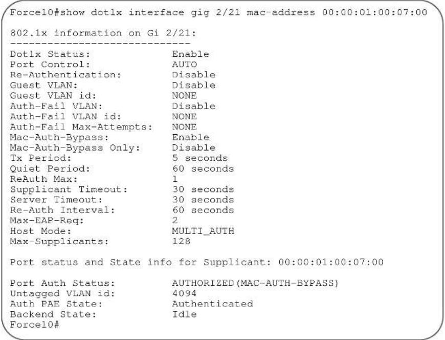
Figure 8-4. show dot1x interface (with Multi-Supplicant Authentication enabled) Example
| Force10#show dotlx interface g 0/21 | |
| 802.1x information on Gi 0/21: | |
| Dotlx Status: | Enable |
| Port Control: | AUTO |
| Re-Authentication: | Disable |
| Guest VLAN: | Enable |
| Guest VLAN id: | 100 |
| Auth-Fail VLAN: | Disable |
| Auth-Fail VLAN id: | NONE |
| Auth-Fail Max-Attempts: | NONE |
| Mac-Auth-Bypass: | Disable |
| Mac-Auth-Bypass Only: | Disable |
| Tx Period: | 30 seconds |
| Quiet Period: | 60 seconds |
| ReAuth Max: | 3 |
| Supplicant Timeout: | 30 seconds |
| Server Timeout: | 30 seconds |
| Re-Auth Interval: | 60 seconds |
| Max-EAP-Req: | 2 |
| Host Mode: | MULTI_AUTH |
| Max-Supplicants: | 128 |
| Port status and State info for Supplicant: 00:00:00:00:00:10 | |
| Port Auth Status: | AUTHORIZED |
| Untagged VLAN id: | 400 |
| Auth PAE State: | Authenticated |
| Backend State: | Idle |
| Port status and State info for Supplicant: 00:00:00:00:00:11 | |
| Port Auth Status: | AUTHORIZED |
| Untagged VLAN id: | 300 |
| Auth PAE State: | Authenticated |
| Backend State: | Idle |
| Port status and State info for Supplicant: 00:00:00:00:00:15 | |
| Port Auth Status: | AUTHORIZED (GUEST-VLAN) |
| Untagged VLAN id: | 100 |
| Auth PAE State: | Authenticated |
| Backend State: | Idle |
Access Control Lists (ACL)
Overview
Access Control Lists (ACLs) are supported on platforms C E S
FTOS supports the following types of Access Control List (ACL), IP prefix list, and route map:
- Commands Common to all ACL Types
• Common IP ACL Commands
• Standard IP ACL Commands
• Extended IP ACL Commands - Common MAC Access List Commands
• Standard MAC ACL Commands - Extended MAC ACL Commands
• IP Prefix List Commands - Route Map Commands
- AS-Path Commands
• IP Community List Commands
Note: For ACL commands used in the Trace function, see the section Trace List Commands in the chapter Security.
Note: For IPv6 ACL commands, see Chapter 26, IPv6 Access Control Lists (IPv6 ACLs).
Commands Common to all ACL Types
The following commands are available within each ACL mode and do not have mode-specific options. Some commands may use similar names, but require different options to support the different ACL types (for example, deny).
- description
- remark
• show config
description

Configure a short text string describing the ACL.
Syntax
Parameters
description text
| text | Enter a text string up to 80 characters long. |
Defaults
Command Modes
Not enabled.
CONFIGURATION-STANDARD-ACCESS-LIST
CONFIGURATION-EXTENDED-ACCESS-LIST
CONFIGURATION-MAC ACCESS LIST-STANDARD
CONFIGURATION-MAC ACCESS LIST-EXTENDED
Command History
Version 8.1.1.0 Introduced on E-Series ExaScale
Version 7.6.1.0 Introduced on S-Series
Version 7.5.1.0 Introduced on C-Series
pre-Version 6.2.1.1 Introduced on E-Series
remark

Enter a description for an ACL entry.
Syntax
remark [remark-number] [description]
Parameters
| remark-number | Enter the remark number. Note that the same sequence number can be used for the remark and an ACL rule.Range: 0 to 4294967290 |
| description | Enter a description of up to 80 characters. |
Defaults
Not configured
Command Modes
CONFIGURATION-STANDARD-ACCESS-LIST
CONFIGURATION-EXTENDED-ACCESS-LIST
CONFIGURATION-MAC ACCESS LIST-STANDARD
CONFIGURATION-MAC ACCESS LIST-EXTENDED
Command History
Version 8.1.1.0 Introduced on E-Series ExaScale
Version 7.6.1.0 Added support for S-Series
Version 7.5.1.0 Added support for C-Series
pre-Version 6.4.1.0 Introduced for E-Series
Usage Information
The remark command is available in each ACL mode. You can configure up to 4294967290 remarks in a given ACL.
The following example shows the use of the remark command twice within the CONFIGURATION-STANDARD-ACCESS-LIST mode. Here, the same sequence number was used for the remark and for an associated ACL rule. The remark will precede the rule in the running-config because it is assumed that the remark is for the rule with the same sequence number, or the group of rules that follow the remark.
Example
Figure 9-1. Command Example: remark
Force10(config-std-nacl)#remark 10 Deny rest of the traffic
Force10(config-std-nacl)#remark 5 Permit traffic from XYZ Inc.
Force10(config-std-nacl)#show config
!
ip access-list standard test
remark 5 Permit traffic from XYZ Inc.
seq 5 permit 1.1.1.0/24
remark 10 Deny rest of the traffic
seq 10 Deny any
Force10(config-std-nacl)#
Related Commands
show config Display the current ACL configuration.
show config

Display the current ACL configuration.
Syntax
show config
Command Modes
CONFIGURATION-STANDARD-ACCESS-LIST
CONFIGURATION-EXTENDED-ACCESS-LIST
CONFIGURATION-MAC ACCESS LIST-STANDARD
CONFIGURATION-MAC ACCESS LIST-EXTENDED
Command History
Version 8.1.1.0 Introduced on E-Series ExaScale
Version 7.6.1.0 Support added for S-Series
Version 7.5.1.0 Support added for C-Series
Version 6.2.1.1 Introduced
Example
Figure 9-2. Command Example: show config
Force10(config-ext-nacl)#show conf
!
ip access-list extended patches
Force10(config-ext-nacl)#
Common IP ACL Commands
The following commands are available within both IP ACL modes (Standard and Extended) and do not have mode-specific options. When an access-list (ACL) is created without any rule and then applied to an interface, ACL behavior reflects an implicit permit.
C and S platforms support Ingress IP ACLs only.
The following commands allow you to clear, display, and assign IP ACL configurations.
- access-class
• clear counters ip access-group - ip access-group
• show ip access-lists
• show ip accounting access-list

Note: See also Commands Common to all ACL Types.
access-class
C E S
Apply a standard ACL to a terminal line.
| Syntax | access-class access-list-name | |
| Parameters | access-list-name | Enter the name of a configured Standard ACL, up to 140 characters. |
| Defaults | Not configured. | |
| Command Modes | LINE | |
| Command History | Version 8.1.1.0 Introduced on E-Series ExaScale | |
| Version 7.8.1.0 Increased name string to accept up to 140 characters. Prior to 7.8.1.0, names are up to 16 characters long. | ||
| Version 7.6.1.0 Support added for S-Series | ||
| Version 7.5.1.0 Support added for C-Series | ||
| pre-Version 6.2.1.1 Introduced | ||
clear counters ip access-group
C E S
Erase all counters maintained for access lists.
| Syntax | clear counters ip access-group [access-list-name] | |
| Parameters | access-list-name | (OPTIONAL) Enter the name of a configured access-list, up to 140 characters. |
| Command Modes | EXEC Privilege | |
| Command History | Version 8.1.1.0 Introduced on E-Series ExaScale | |
| Version 7.8.1.0 Increased name string to accept up to 140 characters. Prior to 7.8.1.0, names are up to 16 characters long. | ||
| Version 7.6.1.0 Support added for S-Series | ||
| Version 7.5.1.0 Support added for C-Series | ||
| pre-Version 6.2.1.1 Introduced | ||
ip access-group

Assign an IP access list (IP ACL) to an interface.
Syntax
ip access-group access-list-name {in | out} [implicit-permit] [vlan vlan-id]
| Parameters | access-list-name | Enter the name of a configured access list, up to 140 characters. |
| in Enter the keyword in to apply the ACL to incoming traffic. | ||
| out | Enter the keyword out to apply the ACL to outgoing traffic.Note: Available only on 12-port 1-Gigabit Ethernet FLEX line card. Refer to your line card documentation for specifications. Not available on S-Series. | |
| implicit-permit | (OPTIONAL) Enter the keyword implicit-permit to change the default action of the ACL from implicit-deny to implicit-permit (that is, if the traffic does not match the filters in the ACL, the traffic is permitted instead of dropped). | |
| vlan vlan-id | (OPTIONAL) Enter the keyword vlan followed by the ID numbers of the VLANs.Range: 1 to 4094, 1-2094 for ExaScale (can used IDs 1-4094) | |
| Defaults | Not enabled. | |
| and Modes | INTERFACE | |
| Command History | Version 8.1.1.0 Introduced on E-Series ExaScale | |
| Version 7.8.1.0 Increased name string to accept up to 140 characters. Prior to 7.8.1.0, names are up to 16 characters long. | ||
| Version 7.6.1.0 Support added for S-Series | ||
| Version 7.5.1.0 Support added for C-Series | ||
| pre-Version 6.2.1.1 Introduced | ||
| Usage Information | You can assign one ACL (standard or extended ACL) to an interface. | |
| Note: This command is supported on the loopback interfaces of EE3, and EF series RPMs. It is not supported on loopback interfaces ED series RPM, or on C-Series or S-Series loopback interfaces. | ||
| When you apply an ACL that filters IGMP traffic, all IGMP traffic is redirected to the CPUs and soft-forwarded, if required, in the following scenarios:on a Layer 2 interface - if a Layer 3 ACL is applied to the interface.on a Layer 3 port or on a Layer 2/Layer 3 port | ||
| Related Commands | ip access-list standard Configure a standard ACL. | |
| ip access-list extended Configure an extended ACL. | ||
show ip access-lists

Display all of the IP ACLs configured in the system, whether or not they are applied to an interface, and the count of matches/mismatches against each ACL entry displayed.
Syntax
show ip access-lists [access-list-name] [interface interface] [in |out]
| Parameters | access-list-name | Enter the name of a configured MAC ACL, up to 140 characters. |
| interface interface | Enter the keywordinterfacefollowed by the one of the following keywords and slot/port or number information:For a 1-Gigabit Ethernet interface, enter the keywordGigabitEthernet followed by the slot/port information.For a Port Channel interface, enter the keywordport-channelfollowed by a number:C-Seriesand S-SeriesRange: 1-128E-SeriesRange: 1 to 255 for TeraScale and 1 - 512 for ExaScale.For a SONET interface, enter the keywordsonetfollowed by the slot/port information.For a 10-Gigabit Ethernet interface, enter the keywordTenGigabitEthernetfollowed by the slot/port information. | |
| in | out | Identify whether ACL is applied on ingress or egress side. | |
| Command Modes | EXEC Privilege | |
| Command History | Version 8.4.1.0 Introduced | |
show ip accounting access-list

Display the IP access-lists created on the switch and the sequence of filters.
Syntax
show ip accounting {access-list access-list-name | cam_count} interface interface
| Parameters | access-list-name | Enter the name of the ACL to be displayed. |
| cam_count | List the count of the CAM rules for this ACL. | |
| interface interface | Enter the keywordinterfacefollowed by the interface type and slot/port or number information:For a 1-Gigabit Ethernet interface, enter the keywordGigabitEthernet followed by the slot/port information.For a Port Channel interface, enter the keywordport-channelfollowed by a number:C-Series and S-Series Range: 1-128E-Series Range: 1 to 32 for EtherScale, 1 to 255 for TeraScale and 1 to 512 for ExaScale.For a SONET interface, enter the keywordsonetfollowed by the slot/port information.For a 10-Gigabit Ethernet interface, enter the keywordTenGigabitEthernetfollowed by the slot/port information. |
Command Modes
EXEC
EXEC Privilege
Command History
Version 7.6.1.0 Support added for S-Series
Version 7.5.1.0 Support added for C-Series
pre-Version 6.2.1.1 Introduced
Example
Figure 9-3. Command Example: show ip accounting access-lists
Force10#show ip accounting access FILTER1 interface gig 1/6
Extended IP access list FILTER1
seq 5 deny ip any 191.1.0.0 /16 count (0x00 packets)
seq 10 deny ip any 191.2.0.0 /16 order 4
seq 15 deny ip any 191.3.0.0 /16
seq 20 deny ip any 191.4.0.0 /16
seq 25 deny ip any 191.5.0.0 /16
Table 9-1 defines the information in Figure 9-3.
Table 9-1. show ip accounting access-lists Command Example Field
| Field Description | |
| “Extended IP...” Displays the name of the IP ACL. | |
| “seq 5...” Displays the filter. If the key words count or byte were configured in the filter, the number of packets or bytes processed by the filter is displayed at the end of the line. | |
| “order 4” Displays the QoS order of priority for the ACL entry. | |
Standard IP ACL Commands
When an ACL is created without any rule and then applied to an interface, ACL behavior reflects an implicit permit.
C and S platforms support Ingress IP ACLs only.
The commands needed to configure a Standard IP ACL are:
- deny
- ip access-list standard
- permit
- resequence access-list
- resequence prefix-list ipv4
• seq

Note: See also Commands Common to all ACL Types and Common IP ACL Commands.
deny

Syntax
Configure a filter to drop packets with a certain IP address.
deny { source [mask] | any | host ip-address} [count [byte] | log] [dscp value] [order] [monitor] [fragments]
To remove this filter, you have two choices:
- Use the no seq sequence-number command syntax if you know the filter's sequence number or
• Use the no deny {source [mask] | any | host ip-address} command.
Parameters
| source | Enter the IP address in dotted decimal format of the network from which the packet was sent. |
| mask | (OPTIONAL) Enter a network mask in /prefix format (/x) or A.B.C.D. The mask, when specified in A.B.C.D format, may be either contiguous or non-contiguous (discontiguous). |
| any | Enter the keyword any to specify that all routes are subject to the filter. |
| host ip-address | Enter the keyword host followed by the IP address to specify a host IP address only. |
| count | (OPTIONAL) Enter the keyword count to count packets processed by the filter. |
| byte | (OPTIONAL) Enter the keyword byte to count bytes processed by the filter. |
| log | (OPTIONAL, E-Series only) Enter the keyword log to enter ACL matches in the log. |
| dscp | (OPTIONAL) Enter the keyword dcsp to match to the IP DCSCP values. |
| order | (OPTIONAL) Enter the keyword order to specify the QoS order of priority for the ACL entry.Range: 0-254 (where 0 is the highest priority and 254 is the lowest; lower order numbers have a higher priority)Default: If the order keyword is not used, the ACLs have the lowest order by default(255). |
| monitor | (OPTIONAL) Enter the keyword monitor when the rule is describing the traffic that you want to monitor and the ACL in which you are creating the rule will be applied to the monitored interface. For details, see the section “Flow-based Monitoring” in the Port Monitoring chapter of the FTOS Configuration Guide. |
| fragments | Enter the keyword fragments to use ACLs to control packet fragments. |
Defaults
Not configured.
Command Modes
CONFIGURATION-STANDARD-ACCESS-LIST
Command History
| Version 8.3.1.0 | Add DSCP value for ACL matching. |
| Version 8.2.1.0 | Allows ACL control of fragmented packets for IP (Layer 3) ACLs. |
| Version 8.1.1.0 | Introduced on E-Series ExaScale |
| Version 7.6.1.0 | Added support for S-Series |
| Version 7.5.1.0 | Added support for C-Series |
| Version 7.4.1.0 | Added support for non-contiguous mask and added the monitor option. |
| Version 6.5.1.0 | Expanded to include the optional QoS order priority for the ACL entry. |
Usage Information
The order option is relevant in the context of the Policy QoS feature only. See the “Quality of Service” chapter of the FTOS Configuration Guide for more information.
When you use the log option, CP processor logs details about the packets that match. Depending on how many packets match the log entry and at what rate, the CP may become busy as it has to log these packets' details.
The monitor option is relevant in the context of flow-based monitoring only. See the Chapter 45, Port Monitoring.
The C-Series and S-Series cannot count both packets and bytes, so when you enter the count byte options, only bytes are incremented.

Note: When ACL logging and byte counters are configured simultaneously, byte counters may display an incorrect value. Configure packet counters with logging instead.
Related Commands
ip access-list standard Configure a standard ACL.
permit Configure a permit filter.
ip access-list standard

Create a standard IP access list (IP ACL) to filter based on IP address.
Syntax
ip access-list standard access-list-name
| Parameters | access-list-name | Enter a string up to 140 characters long as the ACL name. |
| Defaults | All IP access lists contain an implicit “deny any,” that is, if no match occurs, the packet is dropped. | |
| Command Modes | CONFIGURATION | |
| Command History | Version 8.1.1.0 Introduced on E-Series ExaScale | |
| Version 7.8.1.0 Increased name string to accept up to 140 characters. Prior to 7.8.1.0, names are up to 16 characters long. | ||
| Version 7.6.1.0 Added support for S-Series | ||
| Version 7.5.1.0 Added support for C-Series | ||
| Version 7.4.1.0 | Added support for non-contiguous mask and added the monitor option. | |
| Version 6.5.1.0 | Expanded to include the optional QoS order priority for the ACL entry. | |
Usage Information
FTOS supports one ingress and one egress IP ACL per interface.
Prior to 7.8.1.0, names are up to 16 characters long.
The number of entries allowed per ACL is hardware-dependent. Refer to your line card documentation for detailed specification on entries allowed per ACL.
Example
Figure 9-4. Command Example: ip access-list standard
| Force10 (conf) #ip access-list standard TestList |
| Force10 (config-std-nacl) # |
Related Commands
ip access-list extended Create an extended access list.
show config Display the current configuration.
permit

Configure a filter to permit packets from a specific source IP address to leave the switch.
Syntax
permit {source [mask] | any | host ip-address} [count [byte] | log] [dscp value] [order] [monitor]
To remove this filter, you have two choices:
- Use the no seq sequence-number command syntax if you know the filter's sequence number or
• Use the no permit {source [mask] | any | host ip-address} command.
Parameters
| source | Enter the IP address in dotted decimal format of the network from which the packet was sent. |
| mask | (OPTIONAL) Enter a network mask in /prefix format (/x) or A.B.C.D. The mask, when specified in A.B.C.D format, may be either contiguous or non-contiguous. |
| any | Enter the keyword any to specify that all routes are subject to the filter. |
| host ip-address | Enter the keyword host followed by the IP address to specify a host IP address or hostname. |
| count | (OPTIONAL) Enter the keyword count to count packets processed by the filter. |
| dscp | (OPTIONAL) Enter the keyword dscp to match to the IP DSCP values. |
| byte | (OPTIONAL) Enter the keyword byte to count bytes processed by the filter. |
| log | (OPTIONAL, E-Series only) Enter the keyword log to enter ACL matches in the log. |
| order | (OPTIONAL) Enter the keyword order to specify the QoS priority for the ACL entry.Range: 0-254 (where 0 is the highest priority and 254 is the lowest; lower order numbers have a higher priority)Default: If the order keyword is not used, the ACLs have the lowest order by default (255). |
| monitor | (OPTIONAL) Enter the keyword monitor when the rule is describing the traffic that you want to monitor and the ACL in which you are creating the rule will be applied to the monitored interface. For details, see the section “Flow-based Monitoring” in the Port Monitoring chapter of the FTOS Configuration Guide. |
Defaults
Not configured.
Command Modes
CONFIGURATION-STANDARD-ACCESS-LIST
Command History
| Version 8.3.1.0 Add DSCP value for ACL matching. | |
| Version 8.2.1.0 Allows ACL control of fragmented packets for IP (Layer 3) ACLs. | |
| Version 8.1.1.0 Introduced on E-Series ExaScale | |
| Version 7.6.1.0 Added support for S-Series | |
| Version 7.5.1.0 Added support for C-Series | |
| Version 7.4.1.0 | Added support for non-contiguous mask and added the monitor option. |
| Version 6.5.10 | Expanded to include the optional QoS order priority for the ACL entry. |
Usage Information
The order option is relevant in the context of the Policy QoS feature only. See the “Quality of Service” chapter of the FTOS Configuration Guide for more information.
When you use the log option, CP processor logs details about the packets that match. Depending on how many packets match the log entry and at what rate, the CP may become busy as it has to log these packets' details.
The monitor option is relevant in the context of flow-based monitoring only. See Chapter 45, Port Monitoring.
The C-Series and S-Series cannot count both packets and bytes, so when you enter the count byte options, only bytes are incremented.

Note: When ACL logging and byte counters are configured simultaneously, byte counters may display an incorrect value. Configure packet counters with logging instead.
Related Commands
deny Assign a IP ACL filter to deny IP packets. ip access-list standard Create a standard ACL.
resequence access-list

Re-assign sequence numbers to entries of an existing access-list.
Syntax
resequence access-list {ipv4 | ipv6 | mac} {access-list-name StartingSeqNum Step-to-Increment}
Parameters
| ipv4 | ipv6 | mac | Enter the keyword ipv4, or mac to identify the access list type to resequence. |
| access-list-name | Enter the name of a configured IP access list. |
| StartingSeqNum | Enter the starting sequence number to resequence.Range: 0 - 4294967290 |
| Step-to-Increment | Enter the step to increment the sequence number.Range: 1 - 4294967290 |
Defaults
No default values or behavior
Command Modes
EXEC
EXEC Privilege
| Command History | Version 8.2.1.0 Introduced on E-Series ExaScale (IPv6) |
| Version 8.1.1.0 Introduced on E-Series ExaScale (IPv4) | |
| Version 7.8.1.0 Increased name string to accept up to 140 characters. Prior to 7.8.1.0, names are up to 16 characters long. | |
| Version 7.6.1.0 Support added for S-Series | |
| Version 7.5.1.0 Support added for C-Series | |
| Version 7.4.1.0 Introduced | |
| Usage information | When all sequence numbers have been exhausted, this feature permits re-assigning new sequence number to entries of an existing access-list. |
| Related Commands | resequence prefix-list ipv4 Resequence a prefix list |
resequence prefix-list ipv4

Re-assign sequence numbers to entries of an existing prefix list.
Syntax
resequence prefix-list ipv4 {prefix-list-name StartingSeqNum Step-to-increment}
| Parameters | prefix-list-name | Enter the name of configured prefix list, up to 140 characters long. |
| StartingSeqNum | Enter the starting sequence number to resequence.Range: 0 – 65535 | |
| Step-to-Increment | Enter the step to increment the sequence number.Range: 1 – 65535 | |
| Defaults | No default values or behavior | |
| mand Modes | EXEC | |
| EXEC Privilege | ||
| Command History | Version 8.1.1.0 Introduced on E-Series ExaScale | |
| Version 7.8.1.0 Increased name string to accept up to 140 characters. Prior to 7.8.1.0, names are up to 16 characters long. | ||
| Version 7.6.1.0 Added support for S-Series | ||
| Version 7.5.1.0 Added support for C-Series | ||
| Version 7.4.1.0 Introduced | ||
| Usage Information | When all sequence numbers have been exhausted, this feature permits re-assigning new sequence number to entries of an existing prefix list. | |
| Prior to 7.8.1.0, names are up to 16 characters long. | ||
| Related Commands | resequence access-list Resequence an access-list | |
Syntax
Assign a sequence number to a deny or permit filter in an IP access list while creating the filter.
seq sequence-number {deny | permit} {source [mask] | any | host ip-address} } [count [byte] | log] [dscp value] [order] [monitor] [fragments]
Parameters
| sequence-number | Enter a number from 0 to 4294967290. |
| deny | Enter the keyword deny to configure a filter to drop packets meeting this condition. |
| permit | Enter the keyword permit to configure a filter to forward packets meeting this criteria. |
| source | Enter a IP address in dotted decimal format of the network from which the packet was received. |
| mask | (OPTIONAL) Enter a network mask in /prefix format (/x) or A.B.C.D. The mask, when specified in A.B.C.D format, may be either contiguous or non-contiguous. |
| any | Enter the keyword any to specify that all routes are subject to the filter. |
| host ip-address | Enter the keyword host followed by the IP address to specify a host IP address or hostname. |
| count | (OPTIONAL) Enter the keyword count to count packets processed by the filter. |
| byte | (OPTIONAL) Enter the keyword byte to count bytes processed by the filter. |
| log | (OPTIONAL, E-Series only) Enter the keyword log to enter ACL matches in the log. |
| dscp | (OPTIONAL) Enter the keyword dcsp to match to the IP DCSCP values. |
| order | (OPTIONAL) Enter the keyword order to specify the QoS order for the ACL entry.Range: 0-254 (where 0 is the highest priority and 254 is the lowest; lower order numbers have a higher priority)Default: If the order keyword is not used, the ACLs have the lowest order by default (255). |
| monitor | (OPTIONAL) Enter the keyword monitor when the rule is describing the traffic that you want to monitor and the ACL in which you are creating the rule will be applied to the monitored interface. For details, see the section “Flow-based Monitoring” in the Port Monitoring chapter of the FTOS Configuration Guide. |
| fragments | Enter the keyword fragments to use ACLs to control packet fragments. |
Defaults
Not configured
Command Modes
CONFIGURATION-STANDARD-ACCESS-LIST
Command History
| Version 8.3.1.0 Add DSCP value for ACL matching. |
| Version 8.2.1.0 Allows ACL control of fragmented packets for IP (Layer 3) ACLs. |
| Version 8.1.1.0 Introduced on E-Series ExaScale |
| Version 7.6.1.0 Added support for S-Series |
| Version 7.5.1.0 Added support for C-Series |
Usage Information
Version 7.4.1.0 Added support for non-contiguous mask and added the monitor option.
Version 6.5.10 Expanded to include the optional QoS order priority for the ACL entry.
The monitor option is relevant in the context of flow-based monitoring only. See Chapter 45, Port Monitoring.
The order option is relevant in the context of the Policy QoS feature only. The following applies:
- The seq sequence-number is applicable only in an ACL group.
- The order option works across ACL groups that have been applied on an interface via QoS policy framework.
• The order option takes precedence over the seq sequence-number. - If sequence-number is not configured, then rules with the same order value are ordered according to their configuration order.
- If the sequence-number is configured, then the sequence-number is used as a tie breaker for rules with the same order.
When you use the log option, CP processor logs details about the packets that match. Depending on how many packets match the log entry and at what rate, the CP may become busy as it has to log these packets' details.

Note: When ACL logging and byte counters are configured simultaneously, byte counters may display an incorrect value. Configure packet counters with logging instead.
Related Commands
deny Configure a filter to drop packets.
permit Configure a filter to forward packets.
seq Assign a sequence number to a deny or permit filter in an IP access list while creating the filter.
Extended IP ACL Commands
When an ACL is created without any rule and then applied to an interface, ACL behavior reflects an implicit permit.
The following commands configure extended IP ACLs, which in addition to the IP address also examine the packet's protocol type.

and platforms support Ingress IP ACLs only.
- deny
- deny arp
- deny ether-type
- deny icmp
- deny tcp
- deny udp
- ip access-list extended
- permit
-
permit arp
-
permit ether-type
- permit icmp
- permit tcp
- permit udp
- resequence access-list
- resequence prefix-list ipv4
- seq arp
- seq ether-type
- seq

Note: See also Commands Common to all ACL Types and Common IP ACL Commands.
deny

Syntax
Configure a filter that drops IP packets meeting the filter criteria.
deny {ip | ip-protocol-number} {source mask | any | host ip-address} {destination mask | any | host ip-address} [count [byte] | log] [dscp value] [order] [monitor] [fragments]
To remove this filter, you have two choices:
- Use the no seq sequence-number command syntax if you know the filter's sequence number or
- Use the no deny {ip | ip-protocol-number} {source mask | any | host ip-address} {destination mask | any | host ip-address} command.
Parameters
| ip | Enter the keyword ip to configure a generic IP access list. The keyword ip specifies that the access list will deny all IP protocols. |
| ip-protocol-number | Enter a number from 0 to 255 to deny based on the protocol identified in the IP protocol header. |
| source | Enter the IP address of the network or host from which the packets were sent. |
| mask | Enter a network mask in /prefix format (/x) or A.B.C.D. The mask, when specified in A.B.C.D format, may be either contiguous or non-contiguous. |
| any | Enter the keyword any to specify that all routes are subject to the filter. |
| host ip-address | Enter the keyword host followed by the IP address to specify a host IP address. |
| destination | Enter the IP address of the network or host to which the packets are sent. |
| count | (OPTIONAL) Enter the keyword count to count packets processed by the filter. |
| byte | (OPTIONAL) Enter the keyword byte to count bytes processed by the filter. |
| log | (OPTIONAL, E-Series only) Enter the keyword log to enter ACL matches in the log. |
| dscp | (OPTIONAL) Enter the keyword dcsp to match to the IP DCSCP values. |
| order | (OPTIONAL) Enter the keyword order to specify the QoS priority for the ACL entry.Range: 0-254 (where 0 is the highest priority and 254 is the lowest; lower order numbers have a higher priority)Default: If the order keyword is not used, the ACLs have the lowest order by default (255). |
| monitor | (OPTIONAL) Enter the keyword monitor when the rule is describing the traffic that you want to monitor and the ACL in which you are creating the rule will be applied to the monitored interface. For details, see the section “Flow-based Monitoring” in the Port Monitoring chapter of the FTOS Configuration Guide. | |
| fragments | Enter the keyword fragments to use ACLs to control packet fragments. | |
| Defaults | Not configured. | |
| Command Modes | CONFIGURATION-EXTENDED-ACCESS-LIST | |
| Command History | Version 8.3.1.0 Add DSCP value for ACL matching. | |
| Version 8.2.1.0 Allows ACL control of fragmented packets for IP (Layer 3) ACLs. | ||
| Version 8.1.1.0 Introduced on E-Series ExaScale | ||
| Version 7.6.1.0 Added support for S-Series | ||
| Version 7.5.1.0 Added support for C-Series | ||
| Version 7.4.1.0 | Added support for non-contiguous mask and added the monitor option. | |
| Version 6.5.10 | Expanded to include the optional QoS order priority for the ACL entry. | |
| Usage Information | The order option is relevant in the context of the Policy QoS feature only. See the “Quality of Service” chapter of the FTOS Configuration Guide for more information.When you use the log option, CP processor logs details about the packets that match. Depending on how many packets match the log entry and at what rate, the CP may become busy as it has to log these packets’ details.The C-Series and S-Series cannot count both packets and bytes, so when you enter the count byte options, only bytes are incremented.The monitor option is relevant in the context of flow-based monitoring only. See the Chapter 45, Port Monitoring.Note: When ACL logging and byte counters are configured simultaneously, byte counters may display an incorrect value. Configure packet counters with logging instead. | |
| Related Commands | deny tcp Assign a filter to deny TCP packets. | |
| deny udp Assign a filter to deny UDP packets. | ||
| ip access-list extended Create an extended ACL. | ||
| deny arp | Configure an egress filter that drops ARP packets on egress ACL supported line cards (see your line card documentation). | |
| Syntax | deny arp {destination-mac-address mac-address-mask | any} vlan vlan-id {ip-address | any | opcode code-number} [count [byte] | log] [order] [monitor] | |
deny arp
Syntax
To remove this filter, use one of the following:
- Use the no seq sequence-number command syntax if you know the filter's sequence number or
- Use the no deny arp {destination-mac-address mac-address-mask | any} vlan vlan-id {ip-address | any | opcode code-number} command.
Parameters
| destination-mac-address mac-address-mask | Enter a MAC address and mask in the nn:nn:nn:nn:nn format.For the MAC address mask, specify which bits in the MAC address must match.The MAC ACL supports an inverse mask, therefore, a mask of ff:ff:ff:ff:ff allows entries that do not match and a mask of 00:00:00:00:00:00 only allows entries that match exactly. |
| any | Enter the keyword any to match and drop any ARP traffic on the interface. |
| vlan vlan-id | Enter the keyword vlan followed by the VLAN ID to filter traffic associated with a specific VLAN.Range: 1 to 4094, 1-2094 for ExaScale (can used IDs 1-4094)To filter all VLAN traffic specify VLAN 1. |
| ip-address | Enter an IP address in dotted decimal format (A.B.C.D) as the target IP address of the ARP. |
| opcode code-number | Enter the keyword opcode followed by the number of the ARP opcode.Range: 1 to 23. |
| count | (OPTIONAL) Enter the keyword count to count packets processed by the filter. |
| byte | (OPTIONAL) Enter the keyword byte to count bytes processed by the filter. |
| log | (OPTIONAL, E-Series only) Enter the keyword log to have the information kept in an ACL log file. |
| order | (OPTIONAL) Enter the keyword order to specify the QoS priority for the ACL entry.Range: 0-254 (where 0 is the highest priority and 254 is the lowest; lower order numbers have a higher priority)Default: If the order keyword is not used, the ACLs have the lowest order by default (255). |
| monitor | (OPTIONAL) Enter the keyword monitor when the rule is describing the traffic that you want to monitor and the ACL in which you are creating the rule will be applied to the monitored interface. For details, see the section “Flow-based Monitoring” in the Port Monitoring chapter of the FTOS Configuration Guide. |
Defaults
Not configured.
Command Modes
CONFIGURATION-EXTENDED-ACCESS-LIST
Command History
| Version 8.2.1.0 | Allows ACL control of fragmented packets for IP (Layer 3) ACLs. |
| Version 8.1.1.0 | Introduced on E-Series ExaScale |
| Version 7.4.1.0 | Added monitor option |
| Version 6.5.10 | Expanded to include the optional QoS order priority for the ACL entry. |
Usage Information
The order option is relevant in the context of the Policy QoS feature only. See the “Quality of Service” chapter of the FTOS Configuration Guide for more information.
The monitor option is relevant in the context of flow-based monitoring only. See Chapter 45, Port Monitoring.
When you use the log option, CP processor logs details about the packets that match. Depending on how many packets match the log entry and at what rate, the CP may become busy as it has to log these packets' details.
You cannot include IP, TCP or UDP (Layer 3) filters in an ACL configured with ARP or Ether-type (Layer 2) filters. Apply Layer 2 ACLs (ARP and Ether-type) to Layer 2 interfaces only.

Note: When ACL logging and byte counters are configured simultaneously, byte counters may display an incorrect value. Configure packet counters with logging instead.
deny ether-type
E
Configure an egress filter that drops specified types of Ethernet packets on egress ACL supported line cards (see your line card documentation).
Syntax
deny ether-type protocol-type-number {destination-mac-address mac-address-mask | any} vlan vlan-id {source-mac-address mac-address-mask | any} [count [byte] | log] [order] [monitor]
To remove this filter, use one of the following:
- Use the no seq sequence-number command syntax if you know the filter's sequence number or
- Use the no deny ether-type protocol-type-number {destination-mac-address mac-address-mask | any} vlan vlan-id {source-mac-address mac-address-mask | any} command.
Parameters
| protocol-type-number | Enter a number from 600 to FFFF as the specific Ethernet type traffic to drop. |
| destination-mac-address mac-address-mask | Enter a MAC address and mask in the nn:nn:nn:nn:nn format.For the MAC address mask, specify which bits in the MAC address must match.The MAC ACL supports an inverse mask, therefore, a mask of ff:ff:ff:ff:ff:ff allows entries that do not match and a mask of 00:00:00:00:00:00 only allows entries that match exactly. |
| any | Enter the keyword any to match and drop specific Ethernet traffic on the interface. |
| vlan vlan-id | Enter the keyword vlan followed by the VLAN ID to filter traffic associated with a specific VLAN.Range: 1 to 4094, 1-2094 for ExaScale (can used IDs 1-4094)To filter all VLAN traffic specify VLAN 1. |
| source-mac-address mac-address-mask | Enter a MAC address and mask in the nn:nn:nn:nn:nn format.For the MAC address mask, specify which bits in the MAC address must match.The MAC ACL supports an inverse mask, therefore, a mask of ff:ff:ff:ff:ff allows entries that do not match and a mask of 00:00:00:00:00:00 only allows entries that match exactly. |
| count | (OPTIONAL) Enter the keyword count to count packets processed by the filter. |
| byte | (OPTIONAL) Enter the keyword byte to count bytes processed by the filter. |
| log | (OPTIONAL, E-Series only) Enter the keyword log to have the information kept in an ACL log file. |
| order | (OPTIONAL) Enter the keyword order to specify the QoS priority for the ACL entry.Range: 0-254 (where 0 is the highest priority and 254 is the lowest; lower order numbers have a higher priority)Default: If the order keyword is not used, the ACLs have the lowest order by default (255). |
| monitor | (OPTIONAL) Enter the keyword monitor when the rule is describing the traffic that you want to monitor and the ACL in which you are creating the rule will be applied to the monitored interface. For details, see the section “Flow-based Monitoring” in the Port Monitoring chapter of the FTOS Configuration Guide. |
Defaults
Not configured.
Command Modes
CONFIGURATION-EXTENDED-ACCESS-LIST
Command History
Version 8.2.1.0 Allows ACL control of fragmented packets for IP (Layer 3) ACLs.
Version 8.1.1.0 Introduced on E-Series ExaScale
Version 7.4.1.0 Added monitor option
Version 6.5.10 Expanded to include the optional QoS order priority for the ACL entry.
Usage Information
The order option is relevant in the context of the Policy QoS feature only. See the “Quality of Service” chapter of the FTOS Configuration Guide for more information.
When you use the log option, CP processor logs details about the packets that match. Depending on how many packets match the log entry and at what rate, the CP may become busy as it has to log these packets' details.
The monitor option is relevant in the context of flow-based monitoring only. See Chapter 45, Port Monitoring.
You cannot include IP, TCP or UDP (Layer 3) filters in an ACL configured with ARP or Ether-type (Layer 2) filters. Apply Layer 2 ACLs (ARP and Ether-type) to Layer 2 interfaces only.

Note: When ACL logging and byte counters are configured simultaneously, byte counters may display an incorrect value. Configure packet counters with logging instead.
deny icmp

Configure a filter to drop all or specific ICMP messages.
Syntax
deny icmp {source mask|any|host ip-address} {destination mask|any|host ip-address}[dscp][message-type][count [byte] | log] [order][monitor][fragments]
To remove this filter, you have two choices:
- Use the no seq sequence-number command syntax if you know the filter's sequence number or
- Use the no deny icmp {source mask | any | host ip-address} {destination mask | any | host ip-address} command.
Parameters
| source | Enter the IP address of the network or host from which the packets were sent. |
| mask | Enter a network mask in /prefix format (/x) or A.B.C.D. The mask, when specified in A.B.C.D format, may be either contiguous or non-contiguous. |
| any | Enter the keyword any to specify that all routes are subject to the filter. |
| host ip-address | Enter the keyword host followed by the IP address to specify a host IP address. |
| destination | Enter the IP address of the network or host to which the packets are sent. |
| dscp | Enter this keyword to deny a packet based on DSCP value.Range: 0-63 |
| message-type | (OPTIONAL) Enter an ICMP message type, either with the type (and code, if necessary) numbers or with the name of the message type (ICMP message types are listed in Table 9-2).Range: 0 to 255 for ICMP type; 0 to 255 for ICMP code |
| count | (OPTIONAL) Enter the keyword count to count packets processed by the filter. |
| byte | (OPTIONAL) Enter the keyword byte to count bytes processed by the filter. |
| log | (OPTIONAL, E-Series only) Enter the keyword log to have the information kept in an ACL log file. |
| order | (OPTIONAL) Enter the keyword order to specify the QoS priority for the ACL entry.Range: 0-254 (where 0 is the highest priority and 254 is the lowest; lower order numbers have a higher priority)Default: If the order keyword is not used, the ACLs have the lowest order by default (255). |
| monitor | (OPTIONAL) Enter the keyword monitor when the rule is describing the traffic that you want to monitor and the ACL in which you are creating the rule will be applied to the monitored interface. For details, see the section “Flow-based Monitoring” in the Port Monitoring chapter of the FTOS Configuration Guide. |
| fragments | Enter the keyword fragments to use ACLs to control packet fragments. |
Defaults
Not configured
Command Modes
CONFIGURATION-EXTENDED-ACCESS-LIST
Command History
| Version 8.3.1.0 | Added dscp keyword. |
| Version 8.2.1.0 Allows ACL control of fragmented packets for IP (Layer 3) ACLs. | |
| Version 8.1.1.0 | Introduced on E-Series ExaScale |
Usage Information
| Version 7.4.1.0 | Added support for non-contiguous mask and added the monitor option. |
| Version 6.5.10 | Expanded to include the optional QoS order priority for the ACL entry. |
The order option is relevant in the context of the Policy QoS feature only. See the “Quality of Service” chapter of the FTOS Configuration Guide for more information.
When you use the log option, CP processor logs details about the packets that match. Depending on how many packets match the log entry and at what rate, the CP may become busy as it has to log these packets' details.
The monitor option is relevant in the context of flow-based monitoring only. See Chapter 45, Port Monitoring.

Note: When ACL logging and byte counters are configured simultaneously, byte counters may display an incorrect value. Configure packet counters with logging instead.
Table 9-2 lists the keywords displayed in the CLI help and their corresponding ICMP Message Type Name.
Table 9-2. ICMP Message Type Keywords
| Keyword ICMP Message Type | Name |
| administratively-prohibited Administratively prohibited | |
| alternate-address Alternate host address | |
| conversion-error Datagram conversion error | |
| dod-host-prohibited | Host prohibited |
| dod-net-prohibited | Net prohibited |
| echo | Echo |
| echo-reply | Echo reply |
| general-parameter-problem | Parameter problem |
| host-isolated | Host isolated |
| host-precedence-unreachable Host unreachable for precedence | |
| host-redirect | Host redirect |
| host-tos-redirect | Host redirect for TOS |
| host-tos-unreachable | Host unreachable for TOS |
| host-unknown | Host unknown |
| host-unreachable | Host unreachable |
| information-reply | Information replies |
| information-request | Information requests |
| mask-reply | Mask replies |
| mask-request | Mask requests |
| mobile-redirect | Mobile host redirect |
| net-redirect | Network redirect |
| net-tos-redirect | Network redirect for TOS |
| net-tos-unreachable | Network unreachable for TOS |
Table 9-2. ICMP Message Type Keywords
| Keyword | ICMP Message Type Name |
| net-unreachable | Network unreachable |
| network-unknown | Network unknown |
| no-room-for-option Parameter required but no room | |
| option-missing Parameter required but not present | |
| packet-too-big Fragmentation needed and DF set | |
| parameter-problem All parameter problems | |
| port-unreachable | Port unreachable |
| precedence-unreachable | Precedence cutoff |
| protocol-unreachable | Protocol unreachable |
| reassembly-timeout | Reassembly timeout |
| redirect | All redirects |
| router-advertisement | Router discovery advertisements |
| router-solicitation | Router discovery solicitations |
| source-quench | Source quenches |
| source-route-failed | Source route failed |
| time-exceeded | All time exceeded |
| timestamp-reply | Timestamp replies |
| timestamp-request | Timestamp requests |
| traccroute | Traccroute |
| ttl-exceeded | TTL exceeded |
| unreachable | All unreachables |
deny tcp

Syntax
Configure a filter that drops TCP packets meeting the filter criteria.
deny tcp {source mask|any|host ip-address} [bit] [operator port [port]] {destination mask|any|host ip-address} [dscp] [bit] [operator port [port]] [count [byte] | log] [order] [monitor] [fragments]
To remove this filter, you have two choices:
- Use the no seq sequence-number command syntax if you know the filter's sequence number or
- Use the no deny tcp {source mask|any | host ip-address} {destination mask|any | host ip-address} command.
Parameters
| source | Enter the IP address of the network or host from which the packets were sent. |
| mask | Enter a network mask in /prefix format (/x) or A.B.C.D. The mask, when specified in A.B.C.D format, may be either contiguous or non-contiguous. |
| any | Enter the keyword any to specify that all routes are subject to the filter. |
| host ip-address | Enter the keyword host followed by the IP address to specify a host IP address. |
| dscp | Enter this keyword to deny a packet based on DSCP value.Range: 0-63 |
| bit | Enter a flag or combination of bits:ack: acknowledgement fieldfin: finish (no more data from the user)psh: push functionrst: reset the connectionsyn: synchronize sequence numbersurg: urgent field |
| operator | (OPTIONAL) Enter one of the following logical operand:eq = equal toneq = not equal togt = greater thanIt = less thanrange = inclusive range of ports (you must specify two ports for the port command parameter. |
| port port | Enter the application layer port number. Enter two port numbers if using the range logical operand.Range: 0 to 65535.The following list includes some common TCP port numbers:23 = Telnet20 and 21 = FTP25 = SMTP169 = SNMP |
| destination | Enter the IP address of the network or host to which the packets are sent. |
| mask | Enter a network mask in /prefix format (/x) or A.B.C.D. The mask, when specified in A.B.C.D format, may be either contiguous or non-contiguous. |
| count | (OPTIONAL) Enter the keyword count to count packets processed by the filter. |
| byte | (OPTIONAL) Enter the keyword byte to count bytes processed by the filter. |
| log | (OPTIONAL, E-Series only) Enter the keyword log to enter ACL matches in the log. Supported on Jumbo-enabled line cards only. |
| order | (OPTIONAL) Enter the keyword order to specify the QoS priority for the ACL entry.Range: 0-254 (where 0 is the highest priority and 254 is the lowest; lower order numbers have a higher priority)Default: If the order keyword is not used, the ACLs have the lowest order by default (255). |
| monitor | (OPTIONAL) Enter the keyword monitor when the rule is describing the traffic that you want to monitor and the ACL in which you are creating the rule will be applied to the monitored interface. For details, see the section “Flow-based Monitoring” in the Port Monitoring chapter of the FTOS Configuration Guide. |
| fragments | Enter the keyword fragments to use ACLs to control packet fragments. |
Defaults
Not configured.
Command Modes
CONFIGURATION-EXTENDED-ACCESS-LIST
Command History
| Version 8.3.1.0 | Added dscp keyword. |
| Version 8.2.1.0 Allows ACL control of fragmented packets for IP (Layer 3) ACLs. | |
| Version 8.1.1.0 Introduced on E-Series ExaScale | |
| Version 7.6.1.0 Added support for S-Series | |
| Version 7.5.1.0 Added support for C-Series | |
| Version 7.4.1.0 | Added support for non-contiguous mask and added the monitor option. Deprecated established keyword. |
| Version 6.5.10 | Expanded to include the optional QoS order priority for the ACL entry. |
Usage Information
The order option is relevant in the context of the Policy QoS feature only. See the “Quality of Service” chapter of the FTOS Configuration Guide for more information.
When you use the log option, CP processor logs details about the packets that match. Depending on how many packets match the log entry and at what rate, the CP may become busy as it has to log these packets' details.
The C-Series and S-Series cannot count both packets and bytes, so when you enter the count byte options, only bytes are incremented.
The monitor option is relevant in the context of flow-based monitoring only. See Chapter 45, Port Monitoring.

Note: When ACL logging and byte counters are configured simultaneously, byte counters may display an incorrect value. Configure packet counters with logging instead.
Most ACL rules require one entry in the CAM. However, rules with TCP and UDP port operators (gt, lt, range) may require more than one entry. The range of ports is configured in the CAM based on bit mask boundaries; the space required depends on exactly what ports are included in the range.
For example, an ACL rule with TCP port range 4000 - 8000 uses 8 entries in the CAM:
| Rule# | Data | Mask | From | To | #Covered |
| 1 | 0000111110100000 | 1111111111100000 | 4000 | 4031 | 32 |
| 2 | 0000111111000000 | 1111111111000000 | 4032 | 4095 | 64 |
| 3 | 0001000000000000 | 1111100000000000 | 4096 | 6143 | 2048 |
| 4 | 0001100000000000 | 1111110000000000 | 6144 | 7167 | 1024 |
| 5 | 0001110000000000 | 1111111000000000 | 7168 | 7679 | 512 |
| 6 | 0001111000000000 | 1111111100000000 | 7680 | 7935 | 256 |
| 7 | 0001111100000000 | 1111111111000000 | 7936 | 7999 | 64 |
| 8 | 0001111101000000 | 1111111111111111 | 8000 | 8000 | 1 |
Total Ports: 4001
But an ACL rule with TCP port lt 1023 takes only one entry in the CAM:
| Rule# | Data | Mask | From | To | #Covered |
| 1 | 0000000000000000 | 1111110000000000 | 0 | 1023 | 1024 |
| Total Ports: 1024 | |||||
Related Commands
deny Assign a filter to deny IP traffic.
deny udp Assign a filter to deny UDP traffic.
deny udp

Syntax
Configure a filter to drop UDP packets meeting the filter criteria.
deny udp {source mask|any | host ip-address} [operator port [port]] {destination mask|any | host ip-address} [dscp] [operator port [port]] [count [byte] | log] [order] [monitor] [fragments]
To remove this filter, you have two choices:
- Use the no seq sequence-number command syntax if you know the filter's sequence number or
- Use the no deny udp {source mask|any|host ip-address} {destination mask|any|host ip-address} command.
Parameters
| source | Enter the IP address of the network or host from which the packets were sent. |
| mask | Enter a network mask in /prefix format (/x) or A.B.C.D. The mask, when specified in A.B.C.D format, may be either contiguous or non-contiguous. |
| any | Enter the keyword any to specify that all routes are subject to the filter. |
| host ip-address | Enter the keyword host followed by the IP address to specify a host IP address. |
| dscp | Enter this keyword to deny a packet based on DSCP value.Range: 0-63 |
| operator | (OPTIONAL) Enter one of the following logical operand:eq = equal toneq = not equal togt = greater thanlt = less thanrange = inclusive range of ports |
| port port | (OPTIONAL) Enter the application layer port number. Enter two port numbers if using therange logical operand.Range: 0 to 65535 |
| destination | Enter the IP address of the network or host to which the packets are sent. |
| mask | Enter a network mask in /prefix format (/x) or A.B.C.D. The mask, when specified in A.B.C.D format, may be either contiguous or non-contiguous. |
| count | (OPTIONAL) Enter the keyword count to count packets processed by the filter. |
| byte | (OPTIONAL) Enter the keyword byte to count bytes processed by the filter. |
| log | (OPTIONAL, E-Series only) Enter the keyword log to enter ACL matches in the log. Supported on Jumbo-enabled line cards only. |
| order | (OPTIONAL) Enter the keyword order to specify the QoS priority for the ACL entry.Range: 0-254 (where 0 is the highest priority and 254 is the lowest; lower order numbers have a higher priority)Default: If the order keyword is not used, the ACLs have the lowest order by default (255). |
| monitor | (OPTIONAL) Enter the keyword monitor when the rule is describing the traffic that you want to monitor and the ACL in which you are creating the rule will be applied to the monitored interface. For details, see the section “Flow-based Monitoring” in the Port Monitoring chapter of the FTOS Configuration Guide. | |
| fragments | Enter the keyword fragments to use ACLs to control packet fragments. | |
| Defaults | Not configured | |
| Command Modes | CONFIGURATION-EXTENDED-ACCESS-LIST | |
| Command History | Version 8.3.1.0 Added dscp keyword. | |
| Version 8.2.1.0 Allows ACL control of fragmented packets for IP (Layer 3) ACLs. | ||
| Version 8.1.1.0 Introduced on E-Series ExaScale | ||
| Version 7.6.1.0 Added support for S-Series | ||
| Version 7.5.1.0 Added support for C-Series | ||
| Version 7.4.1.0 Added support for non-contiguous mask and added the monitor option. | ||
| Version 6.5.10 Expanded to include the optional QoS order priority for the ACL entry. | ||
| Usage Information | The order option is relevant in the context of the Policy QoS feature only. See the “Quality of Service” chapter of the FTOS Configuration Guide for more information. | |
When you use the log option, CP processor logs details about the packets that match. Depending on how many packets match the log entry and at what rate, the CP may become busy as it has to log these packets' details.
The C-Series and S-Series cannot count both packets and bytes, so when you enter the count byte options, only bytes are incremented.
The monitor option is relevant in the context of flow-based monitoring only. See the Chapter 45, Port Monitoring.

Note: When ACL logging and byte counters are configured simultaneously, byte counters may display an incorrect value. Configure packet counters with logging instead.
Most ACL rules require one entry in the CAM. However, rules with TCP and UDP port operators (gt, lt, range) may require more than one entry. The range of ports is configured in the CAM based on bit mask boundaries; the space required depends on exactly what ports are included in the range.
For example, an ACL rule with TCP port range 4000 - 8000 will use 8 entries in the CAM:
| Rule# | Data | Mask | From | To | #Covered |
| 1 | 0000111110100000 | 1111111111100000 | 4000 | 4031 | 32 |
| 2 | 0000111111000000 | 1111111111000000 | 4032 | 4095 | 64 |
| 3 | 0001000000000000 | 1111100000000000 | 4096 | 6143 | 2048 |
| 4 | 0001100000000000 | 1111110000000000 | 6144 | 7167 | 1024 |
| 5 | 0001110000000000 | 1111111000000000 | 7168 | 7679 | 512 |
| 6 | 0001111000000000 | 1111111100000000 | 7680 | 7935 | 256 |
| 7 | 0001111100000000 | 1111111111000000 | 7936 | 7999 | 64 |
| 8 | 0001111101000000 | 1111111111111111 | 8000 | 8000 | 1 |
Total Ports: 4001
But an ACL rule with TCP port lt 1023 takes only one entry in the CAM:
| Rule# | Data | Mask | From | To | #Covered |
| 1 | 0000000000000000 | 1111110000000000 | 0 | 1023 | 1024 |
| Total Ports: 1024 | |||||
Related Commands
| deny Assign a deny filter for IP traffic. |
| deny tcp Assign a deny filter for TCP traffic. |
ip access-list extended

Name (or select) an extended IP access list (IP ACL) based on IP addresses or protocols.
Syntax
ip access-list extended access-list-name
To delete an access list, use the no ip access-list extended access-list-name command.
Parameters
access-list-name
Enter a string up to 140 characters long as the access list name.
Defaults
All access lists contain an implicit “deny any”; that is, if no match occurs, the packet is dropped.
Command Modes
CONFIGURATION
Command History
Version 8.1.1.0 Introduced on E-Series ExaScale
Version 7.8.1.0 Increased name string to accept up to 140 characters. Prior to 7.8.1.0, names are up to 16 characters long.
Version 7.6.1.0 Support added for S-Series
Version 7.5.1.0 Support added for C-Series
pre-Version 6.2.1.1 Introduced on E-Series
Usage Information
The number of entries allowed per ACL is hardware-dependent. Refer to your line card documentation for detailed specification on entries allowed per ACL.
Prior to 7.8.1.0, names are up to 16 characters long.
Example
Figure 9-5. Command Example: ip access-list extended
Force10 (conf) # ip access-list extended TESTListEXTEND Force10 (config-ext-nacl) #
Related Commands
ip access-list standard Configure a standard IP access list.
show config Display the current configuration.
permit

Syntax
Configure a filter to pass IP packets meeting the filter criteria.
permit {ip | ip-protocol-number} {source mask | any | host ip-address} {destination mask | any | host ip-address} [count [byte] | log] [dscp value] [order] [monitor] [fragments]
To remove this filter, you have two choices:
- Use the no seq sequence-number command syntax if you know the filter's sequence number or
- Use the no deny {ip | ip-protocol-number} {source mask | any | host ip-address} {destination mask | any | host ip-address} command.
Parameters
| ip | Enter the keyword ip to configure a generic IP access list. The keyword ip specifies that the access list will permit all IP protocols. |
| ip-protocol-number | Enter a number from 0 to 255 to permit based on the protocol identified in the IP protocol header. |
| source | Enter the IP address of the network or host from which the packets were sent. |
| mask | Enter a network mask in /prefix format (/x) or A.B.C.D. The mask, when specified in A.B.C.D format, may be either contiguous or non-contiguous. |
| any | Enter the keyword any to specify that all routes are subject to the filter. |
| host ip-address | Enter the keyword host followed by the IP address to specify a host IP address. |
| destination | Enter the IP address of the network or host to which the packets are sent. |
| count | (OPTIONAL) Enter the keyword count to count packets processed by the filter. |
| byte | (OPTIONAL) Enter the keyword byte to count bytes processed by the filter. |
| log | (OPTIONAL, E-Series only) Enter the keyword log to enter ACL matches in the log. |
| dscp | (OPTIONAL) Enter the keyword dcsp to match to the IP DSCP values. |
| order | (OPTIONAL) Enter the keyword order to specify the QoS order of priority for the ACL entry.Range: 0-254 (where 0 is the highest priority and 254 is the lowest; lower order numbers have a higher priority)Default: If the order keyword is not used, the ACLs have the lowest order by default (255). |
| monitor | (OPTIONAL) Enter the keyword monitor when the rule is describing the traffic that you want to monitor and the ACL in which you are creating the rule will be applied to the monitored interface. For details, see the section “Flow-based Monitoring” in the Port Monitoring chapter of the FTOS Configuration Guide. |
| fragments | Enter the keyword fragments to use ACLs to control packet fragments. |
Defaults
Not configured.
Command Modes
CONFIGURATION-EXTENDED-ACCESS-LIST
Command History
| Version 8.3.1.0 | Add DSCP value for ACL matching. |
| Version 8.2.1.0 | Allows ACL control of fragmented packets for IP (Layer 3) ACLs. |
Usage Information
| Version 8.1.1.0 Introduced on E-Series ExaScale | |
| Version 7.6.1.0 Support added for S-Series | |
| Version 7.5.1.0 Support added for C-Series | |
| Version 7.4.1.0 | Added support for non-contiguous mask and added the monitor option. |
| Version 6.5.10 | Expanded to include the optional QoS order priority for the ACL entry. |
The order option is relevant in the context of the Policy QoS feature only. See the “Quality of Service” chapter of the FTOS Configuration Guide for more information.
When you use the log option, CP processor logs details about the packets that match. Depending on how many packets match the log entry and at what rate, the CP may become busy as it has to log these packets' details.
The C-Series and S-Series cannot count both packets and bytes, so when you enter the count byte options, only bytes are incremented.
The monitor option is relevant in the context of flow-based monitoring only. See the Chapter 45, Port Monitoring.

Note: When ACL logging and byte counters are configured simultaneously, byte counters may display an incorrect value. Configure packet counters with logging instead.
Related Commands
ip access-list extended Create an extended ACL.
permit tcp Assign a permit filter for TCP packets.
permit udp Assign a permit filter for UDP packets.
permit arp E
Configure a filter that forwards ARP packets meeting this criteria. This command is supported only on 12-port GE line cards with SFP optics; refer to your line card documentation for specifications.
Syntax
permit arp {destination-mac-address mac-address-mask | any} vlan vlan-id {ip-address | any | opcode code-number} [count [byte] | log] [order] [monitor] [fragments]
To remove this filter, use one of the following:
- Use the no seq sequence-number command syntax if you know the filter's sequence number or
- Use the no permit arp {destination-mac-address mac-address-mask | any} vlan vlan-id {ip-address | any | opcode code-number} command.
Parameters
| destination-mac-addressmac-address-mask | Enter a MAC address and mask in the nn:nn:nn:nn:nn format.For the MAC address mask, specify which bits in the MAC address must match.The MAC ACL supports an inverse mask, therefore, a mask of ff:ff:ff:ff:ff:ff allows entries that do not match and a mask of 00:00:00:00:00:00 only allows entries that match exactly. |
| any | Enter the keywordanyto match and drop any ARP traffic on the interface. |
| vlan vlan-id | Enter the keywordvlanfollowed by the VLAN ID to filter traffic associated with a specific VLAN.Range: 1 to 4094, 1-2094 for ExaScale (can used IDs 1-4094)To filter all VLAN traffic specify VLAN 1. | |
| ip-address | Enter an IP address in dotted decimal format (A.B.C.D) as the target IP address of the ARP. | |
| opcode code-number | Enter the keywordopcodefollowed by the number of the ARP opcode.Range: 1 to 16. | |
| count | (OPTIONAL) Enter the keywordcountto count packets processed by the filter. | |
| byte | (OPTIONAL) Enter the keywordbyteto count bytes processed by the filter. | |
| log | (OPTIONAL, E-Series only) Enter the keywordlogto have the information kept in an ACL log file. | |
| order | (OPTIONAL) Enter the keywordorderto specify the QoS priority for the ACL entry.Range: 0-254 (where 0 is the highest priority and 254 is the lowest; lower order numbers have a higher priority)Default: If the order keyword is not used, the ACLs have the lowest order by default (255). | |
| monitor | (OPTIONAL) Enter the keywordmonitorwhen the rule is describing the traffic that you want to monitor and the ACL in which you are creating the rule will be applied to the monitored interface. For details, see the section “Flow-based Monitoring” in the Port Monitoring chapter of theFTOS Configuration Guide. | |
| fragments | Enter the keywordfragmentsto use ACLs to control packet fragments. | |
| Defaults | Not configured. | |
| Command Modes | CONFIGURATION-EXTENDED-ACCESS-LIST | |
| Command History | Version 8.2.1.0 Allows ACL control of fragmented packets for IP (Layer 3) ACLs. | |
| Version 8.1.1.0 Introduced on E-Series ExaScale | ||
| Version 7.4.1.0 | Added support for non-contiguous mask and added themonitoroption. | |
| Version 6.5.10 | Expanded to include the optional QoSorderpriority for the ACL entry. | |
| Usage Information | Theorderoption is relevant in the context of the Policy QoS feature only. See the “Quality of Service” chapter of theFTOS Configuration Guidefor more information.When you use thelogoption, CP processor logs details about the packets that match. Depending on how many packets match thelogentry and at what rate, the CP may become busy as it has to log these packets’ details.Themonitoroption is relevant in the context of flow-based monitoring only. See theChapter 45, Port Monitoring. | |
You cannot include IP, TCP or UDP filters in an ACL configured with ARP filters.

Note: When ACL logging and byte counters are configured simultaneously, byte counters may display an incorrect value. Configure packet counters with logging instead.
permit ether-type

Configure a filter that allows traffic with specified types of Ethernet packets. This command is supported only on 12-port GE line cards with SFP optics; refer to your line card documentation for specifications.
Syntax
permit ether-type protocol-type-number {destination-mac-address mac-address-mask | any} vlan vlan-id {source-mac-address mac-address-mask | any} [count [byte] | log] [order] [monitor]
To remove this filter, use one of the following:
- Use the no seq sequence-number command syntax if you know the filter's sequence number or
- Use the no permit ether-type protocol-type-number {destination-mac-address mac-address-mask | any} vlan vlan-id {source-mac-address mac-address-mask | any} command.
Parameters
| protocol-type-number | Enter a number from 600 to FFF as the specific Ethernet type traffic to drop. |
| destination-mac-address mac-address-mask | Enter a MAC address and mask in the nn:nn:nn:nn:nn format.For the MAC address mask, specify which bits in the MAC address must match.The MAC ACL supports an inverse mask, therefore, a mask of ff:ff:ff:ff:ff:ff allows entries that do not match and a mask of 00:00:00:00:00:00 only allows entries that match exactly. |
| any | Enter the keyword any to match and drop specific Ethernet traffic on the interface. |
| vlan vlan-id | Enter the keyword vlan followed by the VLAN ID to filter traffic associated with a specific VLAN.Range: 1 to 4094, 1-2094 for ExaScale (can used IDs 1-4094)To filter all VLAN traffic specify VLAN 1. |
| source-mac-address mac-address-mask | Enter a MAC address and mask in the nn:nn:nn:nn:nn format.For the MAC address mask, specify which bits in the MAC address must match.The MAC ACL supports an inverse mask, therefore, a mask of ff:ff:ff:ff:ff:ff allows entries that do not match and a mask of 00:00:00:00:00:00 only allows entries that match exactly. (OPTIONAL) Enter the keyword count to count packets processed by the filter. |
| byte | (OPTIONAL) Enter the keyword byte to count bytes processed by the filter. |
| log | (OPTIONAL, E-Series only) Enter the keyword log to have the information kept in an ACL log file. |
| order | (OPTIONAL) Enter the keyword order to specify the QoS priority for the ACL entry. Range: 0-254 (where 0 is the highest priority and 254 is the lowest; lower order numbers have a higher priority) Default: If the order keyword is not used, the ACLs have the lowest order by default (255). | ||
| monitor | (OPTIONAL) Enter the keyword monitor when the rule is describing the traffic that you want to monitor and the ACL in which you are creating the rule will be applied to the monitored interface. For details, see the section “Flow-based Monitoring” in the Port Monitoring chapter of the FTOS Configuration Guide. | ||
| Defaults | Not configured. | ||
| Command Modes | CONFIGURATION-EXTENDED-ACCESS-LIST | ||
| Command History | Version 8.2.1.0 Allows ACL control of fragmented packets for IP (Layer 3) ACLs. | ||
| Version 8.1.1.0 Introduced on E-Series ExaScale | |||
| Version 7.4.1.0 | Added monitor option | ||
| Version 6.5.10 | Expanded to include the optional QoS order priority for the ACL entry. | ||
| Usage Information | The order option is relevant in the context of the Policy QoS feature only. See the “Quality of Service” chapter of the FTOS Configuration Guide for more information. | ||
| When you use the log option, CP processor logs details about the packets that match. Depending on how many packets match the log entry and at what rate, the CP may become busy as it has to log these packets’ details. | |||
| The monitor option is relevant in the context of the flow-based monitoring feature only. See Chapter 45, Port Monitoring. | |||
| You cannot include IP, TCP or UDP filters in an ACL configured with ARP filters. | |||
| Note: When ACL logging and byte counters are configured simultaneously, byte counters may display an incorrect value. Configure packet counters with logging instead. | |||
permit icmp

Configure a filter to allow all or specific ICMP messages.
Syntax
permit icmp {source mask|any|host ip-address} {destination mask|any|host ip-address} [dscp] [message-type] [count [byte] | log] [order] [monitor] [fragments]
To remove this filter, you have two choices:
- Use the no seq sequence-number command syntax if you know the filter's sequence number or
- Use the no permit icmp {source mask | any | host ip-address} {destination mask | any | host ip-address} command.
Parameters
| source | Enter the IP address of the network or host from which the packets were sent. |
| mask | Enter a network mask in /prefix format (/x) or A.B.C.D. The mask, when specified in A.B.C.D format, may be either contiguous or non-contiguous. |
| any | Enter the keyword any to specify that all routes are subject to the filter. |
| host ip-address | Enter the keyword host followed by the IP address to specify a host IP address. |
| destination | Enter the IP address of the network or host to which the packets are sent. |
| dscp | Enter this keyword to deny a packet based on DSCP value.Range: 0-63 |
| message-type | (OPTIONAL) Enter an ICMP message type, either with the type (and code, if necessary) numbers or with the name of the message type (ICMP message types are listed in Table 9-2).Range: 0 to 255 for ICMP type; 0 to 255 for ICMP code |
| count | (OPTIONAL) Enter the keyword count to count packets processed by the filter. |
| byte | (OPTIONAL) Enter the keyword byte to count bytes processed by the filter. |
| log | (OPTIONAL, E-Series only) Enter the keyword log to have the information kept in an ACL log file. |
| order | (OPTIONAL) Enter the keyword order to specify the QoS priority for the ACL entry.Range: 0-254 (where 0 is the highest priority and 254 is the lowest; lower order numbers have a higher priority)Default: If the order keyword is not used, the ACLs have the lowest order by default (255). |
| monitor | (OPTIONAL) Enter the keyword monitor to monitor traffic on the monitoring interface specified in the flow-based monitoring session along with the filter operation. |
| fragments | Enter the keyword fragments to use ACLs to control packet fragments. |
Defaults
Not configured
Command Modes
CONFIGURATION-STANDARD-ACCESS-LIST
Command History
| Version 8.3.1.0 | Added dscp keyword. |
| Version 8.2.1.0 Allows ACL control of fragmented packets for IP (Layer 3) ACLs. | |
| Version 8.1.1.0 Introduced on E-Series ExaScale | |
| Version 7.4.1.0 | Added support for non-contiguous mask and added the monitor option. |
| Version 6.5.10 | Expanded to include the optional QoS order priority for the ACL entry. |
Usage Information
The order option is relevant in the context of the Policy QoS feature only. See the “Quality of Service” chapter of the FTOS Configuration Guide for more information.
When you use the log option, CP processor logs details about the packets that match. Depending on how many packets match the log entry and at what rate, the CP may become busy as it has to log these packets' details.
The monitor option is relevant in the context of the flow-based monitoring feature only. See Chapter 45, Port Monitoring.

Note: When ACL logging and byte counters are configured simultaneously, byte counters may display an incorrect value. Configure packet counters with logging instead.
permit tcp C E S
Syntax
Configure a filter to pass TCP packets meeting the filter criteria.
permit tcp {source mask|any|host ip-address}[bit][operator port[port]] {destination mask|any|host ip-address}[bit][dscp][operator port[port]][count [byte] | log] [order] [monitor] [fragments]
To remove this filter, you have two choices:
- Use the no seq sequence-number command syntax if you know the filter's sequence number or
- Use the no permit tcp {source mask | any | host ip-address} {destination mask | any | host ip-address} command.
Parameters
| source | Enter the IP address of the network or host from which the packets were sent. |
| mask | Enter a network mask in /prefix format (/x) or A.B.C.D. The mask, when specified in A.B.C.D format, may be either contiguous or non-contiguous. |
| any | Enter the keyword any to specify that all routes are subject to the filter. |
| host ip-address | Enter the keyword host followed by the IP address to specify a host IP address. |
| bit | Enter a flag or combination of bits:ack: acknowledgement fieldfin: finish (no more data from the user)psh: push functionrst: reset the connectionsyn: synchronize sequence numbersurg: urgent field |
| dscp | Enter this keyword to deny a packet based on DSCP value.Range: 0-63 |
| operator | (OPTIONAL) Enter one of the following logical operand:eq = equal toneq = not equal togt = greater thanlt = less thanrange = inclusive range of ports (you must specify two port for the port parameter.) |
| port port | Enter the application layer port number. Enter two port numbers if using the range logical operand.Range: 0 to 65535.The following list includes some common TCP port numbers: 23 = Telnet 20 and 21 = FTP 25 = SMTP 169 = SNMP |
| destination | Enter the IP address of the network or host to which the packets are sent. |
| mask | Enter a network mask in /prefix format (/x) or A.B.C.D. The mask, when specified in A.B.C.D format, may be either contiguous or non-contiguous. |
| count | (OPTIONAL) Enter the keyword count to count packets processed by the filter. |
| byte | (OPTIONAL) Enter the keyword byte to count bytes processed by the filter. |
| log | (OPTIONAL, E-Series only) Enter the keyword log to enter ACL matches in the log. |
| order | (OPTIONAL) Enter the keyword order to specify the QoS priority for the ACL entry.Range: 0-254 (where 0 is the highest priority and 254 is the lowest; lower order numbers have a higher priority)Default: If the order keyword is not used, the ACLs have the lowest order by default (255). |
| monitor | (OPTIONAL) Enter the keyword monitor when the rule is describing the traffic that you want to monitor and the ACL in which you are creating the rule will be applied to the monitored interface. For details, see the section “Flow-based Monitoring” in the Port Monitoring chapter of the FTOS Configuration Guide. |
| fragments | Enter the keyword fragments to use ACLs to control packet fragments. |
Defaults
Not configured.
Command Modes
CONFIGURATION-EXTENDED-ACCESS-LIST
Command History
| Version 8.3.1.0 | Added dscp keyword. |
| Version 8.2.1.0 Allows ACL control of fragmented packets for IP (Layer 3) ACLs. | |
| Version 8.1.1.0 Introduced on E-Series ExaScale | |
| Version 7.6.1.0 Added support for S-Series | |
| Version 7.5.1.0 Added support for C-Series | |
| Version 7.4.1.0 | Added support for non-contiguous mask and added the monitor option. Deprecated established keyword. |
| Version 6.5.10 | Expanded to include the optional QoS order priority for the ACL entry. |
Usage Information
The order option is relevant in the context of the Policy QoS feature only. See the Quality of Service chapter of the FTOS Configuration Guide for more information.

Note: When ACL logging and byte counters are configured simultaneously, byte counters may display an incorrect value. Configure packet counters with logging instead.
The monitor option is relevant in the context of the flow-based monitoring feature only. See Chapter 45, Port Monitoring.
When you use the log option, CP processor logs details about the packets that match. Depending on how many packets match the log entry and at what rate, the CP may become busy as it has to log these packets' details.
The C-Series and S-Series cannot count both packets and bytes, so when you enter the count byte options, only bytes are incremented.
Most ACL rules require one entry in the CAM. However, rules with TCP and UDP port operators (gt, lt, range) may require more than one entry. The range of ports is configured in the CAM based on bit mask boundaries; the space required depends on exactly what ports are included in the range.
For example, an ACL rule with TCP port range 4000 - 8000 uses 8 entries in the CAM:
| Rule# | Data | Mask | From | To | #Covered |
| 1 | 0000111110100000 | 1111111111100000 | 4000 | 4031 | 32 |
| 2 | 0000111111000000 | 1111111111000000 | 4032 | 4095 | 64 |
| 3 | 0001000000000000 | 1111100000000000 | 4096 | 6143 | 2048 |
| 4 | 0001100000000000 | 1111110000000000 | 6144 | 7167 | 1024 |
| 5 | 0001110000000000 | 1111111000000000 | 7168 | 7679 | 512 |
| 6 | 0001111000000000 | 1111111100000000 | 7680 | 7935 | 256 |
| 7 | 0001111100000000 | 1111111111000000 | 7936 | 7999 | 64 |
| 8 | 0001111101000000 | 1111111111111111 | 8000 | 8000 | 1 |
| Total Ports: 4001 | |||||
But an ACL rule with TCP port It 1023 takes only one entry in the CAM:
| Rule# | Data | Mask | From | To | #Covered |
| 1 | 0000000000000000 | 1111110000000000 | 0 | 1023 | 1024 |
| Total Ports: 1024 | |||||
Related Commands
ip access-list extended Create an extended ACL.
permit Assign a permit filter for IP packets.
permit udp Assign a permit filter for UDP packets.
permit udp C E S
Configure a filter to pass UDP packets meeting the filter criteria.
Syntax
permit udp {source mask|any | host ip-address} [operator port [port]] {destination mask|any | host ip-address} [dscp] [operator port [port]] [count [byte] | log] [order] [monitor] [fragments]
To remove this filter, you have two choices:
- Use the no seq sequence-number command syntax if you know the filter's sequence number or
- Use the no permit udp {source mask | any | host ip-address} {destination mask | any | host ip-address} command.
Parameters
| source | Enter the IP address of the network or host from which the packets were sent. |
| mask | Enter a network mask in /prefix format (/x) or A.B.C.D. The mask, when specified in A.B.C.D format, may be either contiguous or non-contiguous. |
| any | Enter the keyword any to specify that all routes are subject to the filter. |
| host ip-address | Enter the keyword host followed by the IP address to specify a host IP address. |
| dscp | Enter this keyword to deny a packet based on DSCP value.Range: 0-63 |
| operator | (OPTIONAL) Enter one of the following logical operand:eq = equal toneq = not equal togt = greater thanlt = less thanrange = inclusive range of ports (you must specify two ports for the port parameter.) |
| port port | (OPTIONAL) Enter the application layer port number. Enter two port numbers if using therange logical operand.Range: 0 to 65535 |
| destination | Enter the IP address of the network or host to which the packets are sent. |
| count | (OPTIONAL) Enter the keyword count to count packets processed by the filter. |
| byte | (OPTIONAL) Enter the keyword byte to count bytes processed by the filter. |
| log | (OPTIONAL, E-Series only) Enter the keyword log to enter ACL matches in the log. |
| order | (OPTIONAL) Enter the keyword order to specify the QoS priority for the ACL entry.Range: 0-254 (where 0 is the highest priority and 254 is the lowest; lower order numbers have a higher priority)Default: If the order keyword is not used, the ACLs have the lowest order by default (255). |
| monitor | (OPTIONAL) Enter the keyword monitor when the rule is describing the traffic that you want to monitor and the ACL in which you are creating the rule will be applied to the monitored interface. For details, see the section “Flow-based Monitoring” in the Port Monitoring chapter of the FTOS Configuration Guide. |
| fragments | Enter the keyword fragments to use ACLs to control packet fragments. |
Defaults
Not configured.
Command Modes
CONFIGURATION-EXTENDED-ACCESS-LIST
Command History
| Version 8.3.1.0 | Added dscp keyword. |
| Version 8.2.1.0 Allows ACL control of fragmented packets for IP (Layer 3) ACLs. | |
| Version 8.1.1.0 | Introduced on E-Series ExaScale |
| Version 7.6.1.0 Added support for S-Series | |
| Version 7.5.1.0 Added support for C-Series | |
| Version 7.4.1.0 | Added support for non-contiguous mask and added the monitor option. |
| Version 6.5.10 | Expanded to include the optional QoS order priority for the ACL entry. |
Usage Information
The order option is relevant in the context of the Policy QoS feature only. See the Quality of Service chapter of the FTOS Configuration Guide for more information.
The monitor option is relevant in the context of the flow-based monitoring feature only. See Chapter 45, Port Monitoring.

Note: When ACL logging and byte counters are configured simultaneously, byte counters may display an incorrect value. Configure packet counters with logging instead.
When you use the log option, CP processor logs details about the packets that match. Depending on how many packets match the log entry and at what rate, the CP may become busy as it has to log these packets' details.
The C-Series and S-Series cannot count both packets and bytes, so when you enter the count byte options, only bytes are incremented.
Most ACL rules require one entry in the CAM. However, rules with TCP and UDP port operators (gt, lt, range) may require more than one entry. The range of ports is configured in the CAM based on bit mask boundaries; the space required depends on exactly what ports are included in the range.
For example, an ACL rule with TCP port range 4000 - 8000 uses 8 entries in the CAM:
| Rule# | Data | Mask | From | To | #Covered |
| 1 | 0000111110100000 | 1111111111100000 | 4000 | 4031 | 32 |
| 2 | 0000111111000000 | 1111111111000000 | 4032 | 4095 | 64 |
| 3 | 0001000000000000 | 1111100000000000 | 4096 | 6143 | 2048 |
| 4 | 0001100000000000 | 1111110000000000 | 6144 | 7167 | 1024 |
| 5 | 0001110000000000 | 1111111000000000 | 7168 | 7679 | 512 |
| 6 | 0001111000000000 | 1111111100000000 | 7680 | 7935 | 256 |
| 7 | 0001111100000000 | 1111111111000000 | 7936 | 7999 | 64 |
| 8 | 0001111101000000 | 1111111111111111 | 8000 | 8000 | 1 |
| Total Ports: 4001 | |||||
But an ACL rule with TCP port It 1023 takes only one entry in the CAM:
| Rule# | Data | Mask | From | To | #Covered |
| 1 | 0000000000000000 | 1111110000000000 | 0 | 1023 | 1024 |
| Total Ports: 1024 | |||||
Related Commands
ip access-list extended Configure an extended ACL.
permit Assign a permit filter for IP packets.
permit tcp Assign a permit filter for TCP packets.
resequence access-list

Re-assign sequence numbers to entries of an existing access-list.
Syntax
resequence access-list {ipv4 | mac} {access-list-name StartingSeqNum Step-to-Increment}
| Parameters | ipv4 | mac | Enter the keyword ipv4, or mac to identify the access list type to resequence. |
| access-list-name | Enter the name of a configured IP access list, up to 140 characters. | |
| StartingSeqNum | Enter the starting sequence number to resequence.Range: 0 - 4294967290 | |
| Step-to-Increment | Enter the step to increment the sequence number.Range: 1 - 4294967290 | |
| Defaults | No default values or behavior | |
| mand Modes | EXEC | |
| EXEC Privilege | ||
| Command History | Version 8.1.1.0 Introduced on E-Series ExaScale | |
| Version 7.8.1.0 Increased name string to accept up to 140 characters. Prior to 7.8.1.0, names are up to 16 characters long. | ||
| Version 7.6.1.0 Added support for S-Series | ||
| Version 7.5.1.0 Added support for C-Series | ||
| Version 7.4.1.0 Introduced for E-Series | ||
| Usage Information | When all sequence numbers have been exhausted, this feature permits re-assigning new sequence number to entries of an existing access-list. | |
| Prior to 7.8.1.0, names are up to 16 characters long. | ||
| Related Commands | resequence prefix-list ipv4 Resequence a prefix list | |
resequence prefix-list ipv4

Re-assign sequence numbers to entries of an existing prefix list.
Syntax
resequence prefix-list ipv4 {prefix-list-name StartingSeqNum Step-to-increment}
| Parameters | prefix-list-name | Enter the name of configured prefix list, up to 140 characters long. |
| StartingSeqNum | Enter the starting sequence number to resequence.Range: 0 – 65535 | |
| Step-to-Increment | Enter the step to increment the sequence number.Range: 1 – 65535 | |
| Defaults | No default values or behavior | |
| mand Modes | EXEC | |
| EXEC Privilege | ||
| Command History | Version 8.1.1.0 Introduced on E-Series ExaScale | |
| Version 7.8.1.0 Increased name string to accept up to 140 characters. Prior to 7.8.1.0, names are up to 16 characters long. | ||
Usage Information
| Version 7.6.1.0 Added support for S-Series |
| Version 7.5.1.0 Added support for C-Series |
| Version 7.4.1.0 Introduced for E-Series |
| When all sequence numbers have been exhausted, this feature permits re-assigning new sequence number to entries of an existing prefix list. |
| Prior to 7.8.1.0, names are up to 16 characters long. |
| resequence access-list Resequence an access-list |
Related Commands
seq arp
E
Configure an egress filter with a sequence number that filters ARP packets meeting this criteria. This command is supported only on 12-port GE line cards with SFP optics; refer to your line card documentation for specifications.
Syntax
seq sequence-number {deny | permit} arp {destination-mac-address mac-address-mask | any} vlan vlan-id {ip-address | any | opcode code-number} [count [byte] | log] [order] [monitor]
To remove this filter, use the no seq sequence-number command.
Parameters
| sequence-number | Enter a number from 0 to 4294967290. |
| deny | Enter the keyword deny to drop all traffic meeting the filter criteria. |
| permit | Enter the keyword permit to forward all traffic meeting the filter criteria. |
| destination-mac-address mac-address-mask | Enter a MAC address and mask in the nn:nn:nn:nn:nn format.For the MAC address mask, specify which bits in the MAC address must match.The MAC ACL supports an inverse mask, therefore, a mask of ff:ff:ff:ff:ff:ff allows entries that do not match and a mask of 00:00:00:00:00:00 only allows entries that match exactly. |
| any | Enter the keyword any to match and drop any ARP traffic on the interface. |
| vlan vlan-id | Enter the keyword vlan followed by the VLAN ID to filter traffic associated with a specific VLAN.Range: 1 to 4094, 1-2094 for ExaScale (can used IDs 1-4094)To filter all VLAN traffic specify VLAN 1. |
| ip-address | Enter an IP address in dotted decimal format (A.B.C.D) as the target IP address of the ARP. |
| opcode code-number | Enter the keyword opcode followed by the number of the ARP opcode.Range: 1 to 16. |
| count | (OPTIONAL) Enter the keyword count to count packets processed by the filter. |
| byte | (OPTIONAL) Enter the keyword byte to count bytes processed by the filter. |
| log | (OPTIONAL, E-Series only) Enter the keyword log to have the information kept in an ACL log file. |
| order | (OPTIONAL) Enter the keyword order to specify the QoS priority for the ACL entry. Range: 0-254 (where 0 is the highest priority and 254 is the lowest; lower order numbers have a higher priority) Default: If the order keyword is not used, the ACLs have the lowest order by default (255). |
| monitor | (OPTIONAL) Enter the keyword monitor when the rule is describing the traffic that you want to monitor and the ACL in which you are creating the rule will be applied to the monitored interface. For details, see the section “Flow-based Monitoring” in the Port Monitoring chapter of the FTOS Configuration Guide. |
Defaults
Not configured.
Command Modes
CONFIGURATION-EXTENDED-ACCESS-LIST
Command History
Version 8.2.1.0 Allows ACL control of fragmented packets for IP (Layer 3) ACLs.
Version 8.1.1.0 Introduced on E-Series ExaScale
Version 7.4.1.0 Added monitor option
Version 6.5.10 Expanded to include the optional QoS order priority for the ACL entry.
Usage Information
The monitor option is relevant in the context of the flow-based monitoring feature only. See Chapter 45, Port Monitoring.
When you use the log option, CP processor logs details about the packets that match. Depending on how many packets match the log entry and at what rate, the CP may become busy as it has to log these packets' details.
The order option is relevant in the context of the Policy QoS feature only. The following applies:
- The seq sequence-number is applicable only in an ACL group.
- The order option works across ACL groups that have been applied on an interface via QoS policy framework.
• The order option takes precedence over the seq sequence-number. - If sequence-number is not configured, then rules with the same order value are ordered according to their configuration order.
- If the sequence-number is configured, then the sequence-number is used as a tie breaker for rules with the same order.

Note: When ACL logging and byte counters are configured simultaneously, byte counters may display an incorrect value. Configure packet counters with logging instead.
You cannot include IP, TCP or UDP (Layer 3) filters in an ACL configured with ARP or Ether-type (Layer 2) filters. Apply Layer 2 ACLs to interfaces in Layer 2 mode.
seq ether-type
E
Configure an egress filter with a specific sequence number that filters traffic with specified types of Ethernet packets. This command is supported only on 12-port GE line cards with SFP optics; refer to your line card documentation for specifications.
Syntax
seq sequence-number {deny | permit} ether-type protocol-type-number {destination-mac-address mac-address-mask | any} vlan vlan-id {source-mac-address mac-address-mask | any} [count [byte] | log] [order] [monitor]
Parameters
| sequence-number | Enter a number from 0 to 4294967290. |
| deny | Enter the keyworddenyto drop all traffic meeting the filter criteria. |
| permit | Enter the keywordpermitto forward all traffic meeting the filter criteria. |
| protocol-type-number | Enter a number from 600 to FFFF as the specific Ethernet type traffic to drop. |
| destination-mac-address mac-address-mask | Enter a MAC address and mask in the nn:nn:nn:nn:nn format.For the MAC address mask, specify which bits in the MAC address must match.The MAC ACL supports an inverse mask, therefore, a mask of ff:ff:ff:ff:ff:ff allows entries that do not match and a mask of 00:00:00:00:00:00 only allows entries that match exactly. |
| any | Enter the keywordanyto match and drop specific Ethernet traffic on the interface. |
| vlan vlan-id | Enter the keywordvlanfollowed by the VLAN ID to filter traffic associated with a specific VLAN.Range: 1 to 4094, 1 to 2094 for ExaScale (can used IDs 1 to 4094)To filter all VLAN traffic specify VLAN 1. |
| source-mac-address mac-address-mask | Enter a MAC address and mask in the nn:nn:nn:nn:nn format.For the MAC address mask, specify which bits in the MAC address must match.The MAC ACL supports an inverse mask, therefore, a mask of ff:ff:ff:ff:ff:ff allows entries that do not match and a mask of 00:00:00:00:00:00 only allows entries that match exactly. (OPTIONAL) Enter the keywordcountto count packets processed by the filter. |
| byte | (OPTIONAL) Enter the keywordbyteto count bytes processed by the filter. |
| log | (OPTIONAL, E-Series only) Enter the keywordlogto have the information kept in an ACL log file. |
| order | (OPTIONAL) Enter the keywordorderto specify the QoS priority for the ACL entry.Range: 0 to 254 (where 0 is the highest priority and 254 is the lowest; lower order numbers have a higher priority)Default: If the order keyword is not used, the ACLs have the lowest order by default (255). |
| monitor | (OPTIONAL) Enter the keywordmonitorwhen the rule is describing the traffic that you want to monitor and the ACL in which you are creating the rule will be applied to the monitored interface. For details, see the section “Flow-based Monitoring” in the Port Monitoring chapter of theFTOS Configuration Guide. |
Defaults
Not configured.
Command Modes
CONFIGURATION-EXTENDED-ACCESS-LIST
Command History
Version 8.2.1.0 Allows ACL control of fragmented packets for IP (Layer 3) ACLs.
Version 8.1.1.0 Introduced on E-Series ExaScale
Version 7.4.1.0 Added monitor option
Version 6.5.10 Expanded to include the optional QoS order priority for the ACL entry.
Usage Information
The monitor option is relevant in the context of the flow-based monitoring feature only. See Chapter 45, Port Monitoring.
When you use the log option, CP processor logs details about the packets that match. Depending on how many packets match the log entry and at what rate, the CP may become busy as it has to log these packets' details.
The order option is relevant in the context of the Policy QoS feature only. The following applies:
- The seq sequence-number is applicable only in an ACL group.
- The order option works across ACL groups that have been applied on an interface via QoS policy framework.
• The order option takes precedence over the seq sequence-number. - If sequence-number is not configured, then rules with the same order value are ordered according to their configuration order.
- If the sequence-number is configured, then the sequence-number is used as a tie breaker for rules with the same order.

Note: When ACL logging and byte counters are configured simultaneously, byte counters may display an incorrect value. Configure packet counters with logging instead.
You cannot include IP, TCP or UDP (Layer 3) filters in an ACL configured with ARP or Ether-type (Layer 2) filters. Apply Layer 2 filters to interfaces in Layer 2 mode.
seq

Assign a sequence number to a deny or permit filter in an extended IP access list while creating the filter.
Syntax
seq sequence-number {deny | permit} {ip-protocol-number | icmp | ip | tcp | udp} {source mask | any | host ip-address} {destination mask | any | host ip-address} [operator port [port]] [count [byte] | log] [dscp value] [order] [monitor] [fragments]
Parameters
| sequence-number | Enter a number from 0 to 4294967290. |
| deny | Enter the keyword deny to configure a filter to drop packets meeting this condition. |
| permit | Enter the keyword permit to configure a filter to forward packets meeting this criteria. |
| ip-protocol-number | Enter a number from 0 to 255 to filter based on the protocol identified in the IP protocol header. |
| icmp | Enter the keyword icmp to configure an ICMP access list filter. |
| ip | Enter the keyword ip to configure a generic IP access list. The keyword ip specifies that the access list will permit all IP protocols. |
| tcp | Enter the keyword tcp to configure a TCP access list filter. |
| udp | Enter the keyword udp to configure a UDP access list filter. |
| source | Enter the IP address of the network or host from which the packets were sent. |
| mask | Enter a network mask in /prefix format (/x) or A.B.C.D. The mask, when specified in A.B.C.D format, may be either contiguous or non-contiguous. |
| any | Enter the keyword any to specify that all routes are subject to the filter. |
| host ip-address | Enter the keyword host followed by the IP address to specify a host IP address. |
| operator | (OPTIONAL) Enter one of the following logical operands:eq = equal toneq = not equal pt = greater thanlt = less thanrange = inclusive range of ports (you must specify two ports for the port parameter.) |
| port port | (OPTIONAL) Enter the application layer port number. Enter two port numbers if using therange logical operand.Range: 0 to 65535The following list includes some common TCP port numbers:23 = Telnet20 and 21 = FTP25 = SMTP169 = SNMP |
| destination | Enter the IP address of the network or host to which the packets are sent. |
| message-type | (OPTIONAL) Enter an ICMP message type, either with the type (and code, if necessary) numbers or with the name of the message type (ICMP message types are listed in Table 9-2).Range: 0 to 255 for ICMP type; 0 to 255 for ICMP code |
| count | (OPTIONAL) Enter the keyword count to count packets processed by the filter. |
| byte | (OPTIONAL) Enter the keyword byte to count bytes processed by the filter. |
| log | (OPTIONAL, E-Series only) Enter the keyword log to enter ACL matches in the log. Supported on Jumbo-enabled line cards only. |
| dscp | (OPTIONAL) Enter the keyword dcsp to match to the IP DCSCP values. |
| order | (OPTIONAL) Enter the keyword order to specify the QoS priority for the ACL entry.Range: 0-254 (where 0 is the highest priority and 254 is the lowest; lower order numbers have a higher priority)Default: If the order keyword is not used, the ACLs have the lowest order by default (255). |
| monitor | (OPTIONAL) Enter the keyword monitor when the rule is describing the traffic that you want to monitor and the ACL in which you are creating the rule will be applied to the monitored interface. For details, see the section “Flow-based Monitoring” in the Port Monitoring chapter of the FTOS Configuration Guide. |
| fragments | Enter the keyword fragments to use ACLs to control packet fragments. |
Defaults
Not configured
Command Modes
CONFIGURATION-EXTENDED-ACCESS-LIST
Command History
| Version 8.3.1.0 Add DSCP value for ACL matching. | |
| Version 8.2.1.0 Allows ACL control of fragmented packets for IP (Layer 3) ACLs. | |
| Version 8.1.1.0 Introduced on E-Series ExaScale | |
| Version 7.6.1.0 Added support for S-Series | |
| Version 7.5.1.0 Added support for C-Series | |
| Version 7.4.1.0 | Added support for non-contiguous mask and added themonitoroption. Deprecated establishedkeyword |
| Version 6.5.10 | Expanded to include the optional QoSorderpriority for the ACL entry. |
Usage Information
The monitor option is relevant in the context of the flow-based monitoring feature only. See Chapter 45, Port Monitoring.
When you use the log option, CP processor logs details about the packets that match. Depending on how many packets match the log entry and at what rate, the CP may become busy as it has to log these packets' details.
The order option is relevant in the context of the Policy QoS feature only. The following applies:
- The seq sequence-number is applicable only in an ACL group.
- The order option works across ACL groups that have been applied on an interface via QoS policy framework.
• The order option takes precedence over the seq sequence-number. - If sequence-number is not configured, then rules with the same order value are ordered according to their configuration order.
- If the sequence-number is configured, then the sequence-number is used as a tie breaker for rules with the same order.
If the sequence-number is configured, then the sequence-number is used as a tie breaker for rules with the same order.

Note: When ACL logging and byte counters are configured simultaneously, byte counters may display an incorrect value. Configure packet counters with logging instead.
Related Commands
deny Configure a filter to drop packets.
permit Configure a filter to forward packets.
Common MAC Access List Commands
The following commands are available within both MAC ACL modes (Standard and Extended) and do not have mode-specific options.
C and S platforms support Ingress MAC ACLs only.
The following commands allow you to clear, display and assign MAC ACL configurations.
• clear counters mac access-group
- mac access-group
• show mac access-lists
• show mac accounting access-list
clear counters mac access-group

Clear counters for all or a specific MAC ACL.
Syntax
clear counters mac access-group [mac-list-name]
| Parameters | mac-list-name (OPTIONAL) Enter the name of a configured MAC access list. |
| Command Modes | EXEC Privilege |
| Command History | Version 8.1.1.0 Introduced on E-Series ExaScale |
| Version 7.6.1.0 Support added for S-Series | |
| Version 7.5.1.0 Support added for C-Series | |
| pre-Version 6.1.1.0 Introduced for E-Series |
mac access-group

Apply a MAC ACL to traffic entering or exiting an interface.
Syntax
mac access-group access-list-name {in [vlan vlan-range] | out}
| Parameters | access-list-name | Enter the name of a configured MAC access list, up to 140 characters. |
| vlan vlan-range | (OPTIONAL) Enter the keywordvlan followed a range of VLANs. Note that this option is available only with theinkeyword option.Range: 1 to 4094, 1 to 2094 for ExaScale (can used IDs 1 to 4094) | |
| in | Enter the keywordinto configure the ACL to filter incoming traffic. | |
| out | Enter the keywordoutto configure the ACL to filter outgoing traffic. Not available on S-Series. | |
| Defaults | No default behavior or configuration | |
| Command Modes | INTERFACE | |
| Command History | Version 8.1.1.0 Introduced on E-Series ExaScale | |
| Version 7.8.1.0 Increased name string to accept up to 140 characters. Prior to 7.8.1.0, names are up to 16 characters long. | ||
| Version 7.6.1.0 Support added for S-Series | ||
| Version 7.5.1.0 Support added for C-Series | ||
| pre-Version 6.1.1.0 Introduced for E-Series | ||
| Usage Information | You can assign one ACL (standard or extended) to an interface. | |
| Prior to 7.8.1.0, names are up to 16 characters long. | ||
| Related Commands | mac access-list standard Configure a standard MAC ACL. | |
| mac access-list extended Configure an extended MAC ACL. | ||
show mac access-lists

Display all of the Layer 2 ACLs configured in the system, whether or not they are applied to an interface, and the count of matches/mismatches against each ACL entry displayed.
Syntax
show mac access-lists [access-list-name] [interface interface] [in | out]
| Parameters | access-list-name | Enter the name of a configured MAC ACL, up to 140 characters. |
| interface interface | Enter the keywordinterfacefollowed by the one of the following keywords and slot/port or number information:For a 1-Gigabit Ethernet interface, enter the keywordGigabitEthernet followed by the slot/port information.For a Port Channel interface, enter the keywordport-channelfollowed by a number:C-Seriesand S-SeriesRange: 1 to 128E-SeriesRange: 1 to 255 for TeraScale and 1 to 512 for ExaScale.For a SONET interface, enter the keywordsonetfollowed by the slot/port information.For a 10-Gigabit Ethernet interface, enter the keywordTenGigabitEthernetfollowed by the slot/port information. | |
| in | out | Identify whether ACL is applied on ingress or egress side. |
Command Modes
EXEC Privilege
Command History
Version 8.4.1.0 Introduced
show mac accounting access-list

Display MAC access list configurations and counters (if configured).
Syntax
show mac accounting access-list access-list-name interface interface in | out
Parameters
| access-list-name | Enter the name of a configured MAC ACL, up to 140 characters. |
| interface interface | Enter the keywordinterfacefollowed by the one of the following keywords and slot/port or number information:For a 1-Gigabit Ethernet interface, enter the keywordGigabitEthernet followed by the slot/port information.For a Port Channel interface, enter the keywordport-channel followed by a number:C-Seriesand S-SeriesRange: 1 to 128E-SeriesRange: 1 to 32 for EtherScale, 1 to 255 for TeraScale and 1 to 512 for ExaScale.For a SONET interface, enter the keywordsonetfollowed by the slot/port information.For a 10-Gigabit Ethernet interface, enter the keywordTenGigabitEthernetfollowed by the slot/port information. |
| in | out | Identify whether ACL is applied ay Ingress (in) or egress (out) side. |
Command Modes
EXEC
EXEC Privilege
Command History
Version 8.1.1.0 Introduced on E-Series ExaScale
| Version 7.8.1.0 Increased name string to accept up to 140 characters. Prior to 7.8.1.0, names are up to 16 characters long. |
Version 7.6.1.0 Support added for S-Series
Version 7.5.1.0 Support added for C-Series
pre-Version 6.1.1.0 Introduced for E-Series
Example
Figure 9-6. Command Example: show mac accounting access-list
| Force10#show mac accounting access-list mac-ext interface po 1Extended mac access-list mac-ext on GigabitEthernet 0/11 | ||||
| seq 5 permit host 00:00:00:00:00:11 host 00:00:00:00:00:19 count (393794576 packets) | ||||
| seq 10 deny host 00:00:00:00:00:21 host 00:00:00:00:00:29 count (89076777 packets) | ||||
| seq 15 deny host 00:00:00:00:00:31 host 00:00:00:00:00:39 count (0 packets) | ||||
| seq 20 deny host 00:00:00:00:00:41 host 00:00:00:00:00:49 count (0 packets) | ||||
| seq 25 permit any any count (0 packets) | ||||
| Extended mac access-list mac-ext on GigabitEthernet 0/12 | ||||
| seq 5 permit host 00:00:00:00:00:11 host 00:00:00:00:00:19 count (57589834 packets) | ||||
| seq 10 deny host 00:00:00:00:00:21 host 00:00:00:00:00:29 count (393143077 packets) | ||||
| seq 15 deny host 00:00:00:00:00:31 host 00:00:00:00:00:39 count (0 packets) | ||||
| seq 20 deny host 00:00:00:00:00:41 host 00:00:0O:00:00:49 count (0 packets) | ||||
| seq 25 permit any any count (0 packets) | ||||
| Force10# |
Usage Information
The ACL hit counters in this command increment the counters for each matching rule, not just the first matching rule.
Related Commands
| show mac accounting destination Display destination counters for Layer 2 traffic (available on physical interfaces only). |
Standard MAC ACL Commands
When an access-list is created without any rule and then applied to an interface, ACL behavior reflects implicit permit.
C and S platforms support Ingress MAC ACLs only.
The following commands configure standard MAC ACLs:
- deny
• mac access-list standard - permit
• seq

Note: See also Commands Common to all ACL Types and Common MAC Access List Commands.
Configure a filter to drop packets with a the MAC address specified.
Syntax
deny {any | mac-source-address [mac-source-address-mask]} [count [byte]] [log] [monitor]
To remove this filter, you have two choices:
- Use the no seq sequence-number command syntax if you know the filter's sequence number or
• Use the no deny {any | mac-source-address mac-source-address-mask} command.
Parameters
| any | Enter the keyword any to specify that all traffic is subject to the filter. |
| mac-source-address | Enter a MAC address in nn:nn:nn:nn:nn:nn format. |
| mac-source-address-mask | (OPTIONAL) Specify which bits in the MAC address must match. If no mask is specified, a mask of 00:00:00:00:00:00 is applied (in other words, the filter allows only MAC addresses that match). |
| count | (OPTIONAL) Enter the keyword count to count packets processed by the filter. |
| byte | (OPTIONAL) Enter the keyword byte to count bytes processed by the filter. |
| log | (OPTIONAL, E-Series only) Enter the keyword log to log the packets. |
| monitor (OPTIONAL) Enter the keyword monitor when the rule is describing the traffic that you want to monitor and the ACL in which you are creating the rule will be applied to the monitored interface. For details, see the section “Flow-based Monitoring” in the Port Monitoring chapter of the FTOS Configuration Guide. | |
Defaults
Not enabled.
Command Modes
CONFIGURATION-MAC ACCESS LIST-STANDARD
Command History
| Version 8.1.1.0 Introduced on E-Series ExaScale | |
| Version 7.6.1.0 Support added for S-Series | |
| Version 7.5.1.0 Support added for C-Series | |
| Version 7.4.1.0 Added monitor option | |
| pre-Version 6.1.1.0 Introduced for E-Series |

Note: When ACL logging and byte counters are configured simultaneously, byte counters may display an incorrect value. Configure packet counters with logging instead.
Usage Information
When you use the log option, CP processor logs details about the packets that match. Depending on how many packets match the log entry and at what rate, the CP may become busy as it has to log these packets' details.
Related Commands
permit Configure a MAC address filter to pass packets. seq Configure a MAC address filter with a specified sequence number.
mac access-list standard

Name a new or existing MAC access control list (MAC ACL) and enter the MAC ACCESS LIST mode to configure a standard MAC ACL. See Commands Common to all ACL Types and Common MAC Access List Commands.
Syntax
mac access-list standard mac-list-name
| Parameters | mac-list-name | Enter a text string as the name of the standard MAC access list (140 character maximum). |
| Defaults | Not configured | |
| Command Modes | CONFIGURATION | |
| Command History | Version 8.1.1.0 Introduced on E-Series ExaScale | |
| Version 7.8.1.0 Increased name string to accept up to 140 characters. Prior to 7.8.1.0, names are up to 16 characters long. | ||
| Version 7.6.1.0 Support added for S-Series | ||
| Version 7.5.1.0 Support added for C-Series | ||
| pre-Version 6.1.1.0 Introduced for E-Series | ||
Usage Information
FTOS supports one ingress and one egress MAC ACL per interface.
Prior to 7.8.1.0, names are up to 16 characters long.
The number of entries allowed per ACL is hardware-dependent. Refer to your line card documentation for detailed specification on entries allowed per ACL.
C-Series and S-Series support ingress ACLs only.
Example
Figure 9-7. Command Example: mac-access-list standard
| Force10 (conf) #mac-access-list access-list standard TestMAC | |
| Force10 (config-std-macl) #? | |
| deny | Specify packets to reject |
| description | List description |
| exit | Exit from access-list configuration mode |
| no | Negate a command or set its defaults |
| permit | Specify packets to forward |
| remark | Specify access-list entry remark |
| seq | Sequence numbers |
| show | Show Standard ACL configuration |
permit

Configure a filter to forward packets from a specific source MAC address.
Syntax
permit {any | mac-source-address [mac-source-address-mask]} [count [byte]] | [log] [monitor]
To remove this filter, you have two choices:
- Use the no seq sequence-number command syntax if you know the filter's sequence number or
• Use the no permit {any | mac-source-address mac-source-address-mask} command.
Parameters
| any | Enter the keyword any to forward all packets received with a MAC address. |
| mac-source-address | Enter a MAC address in nn:nn:nn:nn:nn:nn format. |
| mac-source-address-mask | (OPTIONAL) Specify which bits in the MAC address must match. If no mask is specified, a mask of 00:00:00:00:00:00 is applied (in other words, the filter allows only MAC addresses that match). |
| count | (OPTIONAL) Enter the keyword count to count packets processed by the filter. |
| byte | (OPTIONAL) Enter the keyword byte to count bytes processed by the filter. |
| log | (OPTIONAL, E-Series only) Enter the keyword log to log the packets. |
| monitor (OPTIONAL) Enter the keyword monitor when the rule is describing the traffic that you want to monitor and the ACL in which you are creating the rule will be applied to the monitored interface. For details, see the section “Flow-based Monitoring” in the Port Monitoring chapter of the FTOS Configuration Guide. | |
Defaults Command Modes
Not configured.
Command History
CONFIGURATION-MAC ACCESS LIST-STANDARD
| Version 8.1.1.0 Introduced on E-Series ExaScale |
| Version 7.6.1.0 Support added for S-Series |
| Version 7.5.1.0 Support added for C-Series |
| pre-Version 6.1.1.0 Introduced for E-Series |
Usage Information
Note: When ACL logging and byte counters are configured simultaneously, byte counters may display an incorrect value. Configure packet counters with logging instead.
When you use the log option, CP processor logs details about the packets that match. Depending on how many packets match the log entry and at what rate, the CP may become busy as it has to log these packets' details.
Related Commands
| deny Configure a MAC ACL filter to drop packets. |
| seq Configure a MAC ACL filter with a specified sequence number. |
seq

Syntax
Assign a sequence number to a deny or permit filter in a MAC access list while creating the filter.
seq sequence-number {deny | permit} {any | mac-source-address [mac-source-address-mask]} [count [byte]] [log] [monitor]
Parameters
| sequence-number | Enter a number between 0 and 65535. |
| deny | Enter the keyworddenyto configure a filter to drop packets meeting this condition. |
| permit | Enter the keywordpermitto configure a filter to forward packets meeting this criteria. |
| any Enter the keywordanyto filter all packets. | |
| mac-source-address | Enter a MAC address in nn:nn:nn:nn:nn:nn format. |
| mac-source-address-mask | (OPTIONAL) Specify which bits in the MAC address must match. If no mask is specified, a mask of 00:00:00:00:00:00 is applied (in other words, the filter allows only MAC addresses that match). |
| count | (OPTIONAL) Enter the keywordcountto count packets processed by the filter. |
| byte | (OPTIONAL) Enter the keywordbyteto count bytes processed by the filter. |
| log | (OPTIONAL, E-Series only) Enter the keywordlogto log the packets. |
| monitor(OPTIONAL) Enter the keywordmonitorwhen the rule is describing the traffic that you want to monitor and the ACL in which you are creating the rule will be applied to the monitored interface. For details, see the section “Flow-based Monitoring” in the Port Monitoring chapter of theFTOS Configuration Guide. | |
Defaults
Not configured.
Command Modes
CONFIGURATION-MAC ACCESS LIST-STANDARD
Command History
| Version 8.1.1.0 Introduced on E-Series ExaScale |
| Version 7.6.1.0 Support added for S-Series |
| Version 7.5.1.0 Support added for C-Series |
| Version 7.4.1.0 Added monitor option |
| pre-Version 6.1.1.0 Introduced for E-Series |

Note: When ACL logging and byte counters are configured simultaneously, byte counters may display an incorrect value. Configure packet counters with logging instead.
Usage Information
When you use the log option, CP processor logs details about the packets that match. Depending on how many packets match the log entry and at what rate, the CP may become busy as it has to log these packets' details.
Related Commands
deny Configure a filter to drop packets. permit Configure a filter to forward packets.
Extended MAC ACL Commands
When an access-list is created without any rule and then applied to an interface, ACL behavior reflects implicit permit.
C and S platforms support Ingress MAC ACLs only.
The following commands configure Extended MAC ACLs.
- deny
• mac access-list extended - permit
• seq

Note: See also Commands Common to all ACL Types and Common MAC Access List Commands.
deny

Syntax
Configure a filter to drop packets that match the filter criteria.
deny {any | host mac-address | mac-source-address mac-source-address-mask} {any | host mac-address | mac-destination-address mac-destination-address-mask} [ethertype-operator] [count [byte]] [log] [monitor]
To remove this filter, you have two choices:
- Use the no seq sequence-number command syntax if you know the filter's sequence number or
- Use the no deny {any | host mac-address | mac-source-address mac-source-address-mask} {any | host mac-address | mac-destination-address mac-destination-address-mask} command.
Parameters
| any Enter the keyword any to drop all packets. | |
| host mac-address | Enter the keyword host followed by a MAC address to drop packets with that host address. |
| mac-source-address | Enter the source MAC address in nn:nn:nn:nn:nn:nn format. |
| mac-source-address-mask | Specify which bits in the MAC address must match.The MAC ACL supports an inverse mask, therefore, a mask of ff:ff:ff:ff:ff:ff allows entries that do not match and a mask of 00:00:00:00:00:00 only allows entries that match exactly. |
| mac-destination-address | Enter the destination MAC address and mask in nn:nn:nn:nn:nn:nn format. |
| mac-destination-address-mask | Specify which bits in the MAC address must match.The MAC ACL supports an inverse mask, therefore, a mask of ff:ff:ff:ff:ff:ff allows entries that do not match and a mask of 00:00:00:00:00:00 only allows entries that match exactly. |
| ethertype operator | (OPTIONAL) To filter based on protocol type, enter one of the following Ethertypes:ev2 - is the Ethernet II frame format.llc - is the IEEE 802.3 frame format.snap - is the IEEE 802.3 SNAP frame format. | |
| count (OPTIONAL) Enter the keyword count to count packets processed by the filter. | ||
| byte (OPTIONAL) Enter the keyword byte to count bytes processed by the filter. | ||
| log | (OPTIONAL, E-Series only) Enter the keyword log to log the packets. | |
| monitor (OPTIONAL) Enter the keyword monitor when the rule is describing the traffic that you want to monitor and the ACL in which you are creating the rule will be applied to the monitored interface. For details, see the section “Flow-based Monitoring” in the Port Monitoring chapter of the FTOS Configuration Guide. | ||
| Defaults | Not configured. | |
| Command Modes | CONFIGURATION-MAC ACCESS LIST-EXTENDED | |
| Command History | Version 8.1.1.0 Introduced on E-Series ExaScale | |
| Version 7.6.1.0 Support added for S-Series | ||
| Version 7.5.1.0 Support added for C-Series | ||
| Version 7.4.1.0 Added monitor option | ||
| pre-Version 6.1.1.0 Introduced for E-Series | ||
| Usage Information | Note: When ACL logging and byte counters are configured simultaneously, byte counters may display an incorrect value. Configure packet counters with logging instead. | |
| When you use the log option, CP processor logs details about the packets that match. Depending on how many packets match the log entry and at what rate, the CP may become busy as it has to log these packets' details. | ||
| Related Commands | permit Configure a filter to forward based on MAC addresses. | |
| seq Configure a filter with specific sequence numbers. | ||
mac access-list extended

Name a new or existing extended MAC access control list (extended MAC ACL).
Syntax
mac access-list extended access-list-name
Parameters
access-list-name
Enter a text string as the MAC access list name, up to 140 characters.
Defaults
No default configuration
Command Modes
CONFIGURATION
Command History
Version 8.1.1.0 Introduced on E-Series ExaScale
Version 7.8.1.0 Increased name string to accept up to 140 characters. Prior to 7.8.1.0, names are up to 16 characters long.
Version 7.6.1.0 Support added for S-Series
Version 7.5.1.0 Support added for C-Series
pre-Version 6.1.1.0 Introduced for E-Series
Usage Information
The number of entries allowed per ACL is hardware-dependent. Refer to your line card documentation for detailed specification on entries allowed per ACL.
Prior to 7.8.1.0, names are up to 16 characters long.
Example
Figure 9-8. Command Example: mac-access-list extended
Force10 (conf) #mac-access-list access-list extended TestMATExt
Force10 (config-ext-macl) #remark 5 IPv4
Force10(config-ext-macl)#seq 10 permit any any ev2 eq 800 count bytes
Force10 (config-ext-macl) #remark 15 ARP
Forcel0(config-ext-macl)#seq 20 permit any any ev2 eq 806 count bytes
Force10 (config-ext-macl) #remark 25 IPv6
Force10(config-ext-macl)#seq 30 permit any any ev2 eq 86dd count bytes
Forcel0(config-ext-macl)#seq 40 permit any any count bytes
Forcel0 (config-ext-macl) #exit
Force10(conf)#do show mac accounting access-list snickers interface g0/47 in
Extended mac access-list snickers on GigabitEthernet 0/47
seq 10 permit any any ev2 eq 800 count bytes (559851886 packets 191402152148
bytes)
seq 20 permit any any ev2 eq 806 count bytes (74481486 packets 5031686754
bytes)
seq 30 permit any any ev2 eq 86dd count bytes (7751519 packets 797843521 bytes)
Related Commands
mac access-list standard Configure a standard MAC access list.
show mac accounting access-list
Display MAC access list configurations and counters (if configured).
permit

Configure a filter to pass packets matching the criteria specified.
Syntax
permit {any | host mac-address | mac-source-address mac-source-address-mask} {any | host mac-address | mac-destination-address mac-destination-address-mask} [ethertype operator] [count [byte]] | [log] [monitor]
To remove this filter, you have two choices:
- Use the no seq sequence-number command syntax if you know the filter's sequence number or
- Use the no permit {any | host mac-address | mac-source-address mac-source-address-mask} {any | mac-destination-address mac-destination-address-mask} command.
Parameters
| any Enter the keyword any to forward all packets. | |
| host Enter the keyword host followed by a MAC address to forward packets with that host address. | |
| mac-source-address | Enter the source MAC address in nn:nn:nn:nn:nn:nn format. |
| mac-source-address-mask | Specify which bits in the MAC address must be matched.The MAC ACL supports an inverse mask, therefore, a mask of ff:ff:ff:ff:ff:ff allows entries that do not match and a mask of 00:00:00:00:00:00 only allows entries that match exactly. |
| mac-destination-address | Enter the destination MAC address and mask in nn:nn:nn:nn:nn:nn format. |
| mac-destination-address-mask | Specify which bits in the MAC address must be matched.The MAC ACL supports an inverse mask, therefore, a mask of ff:ff:ff:ff:ff:ff allows entries that do not match and a mask of 00:00:00:00:00:00 only allows entries that match exactly. |
| ethertype operator | (OPTIONAL) To filter based on protocol type, enter one of the following Ethertypes:ev2 - is the Ethernet II frame format.llc - is the IEEE 802.3 frame format.snap - is the IEEE 802.3 SNAP frame format. |
| count (OPTIONAL) Enter the keyword count to count packets processed by the filter. | |
| byte (OPTIONAL) Enter the keyword byte to count bytes processed by the filter. | |
| log | (OPTIONAL, E-Series only) Enter the keyword log to log the packets. |
| monitor (OPTIONAL) Enter the keyword monitor when the rule is describing the traffic that you want to monitor and the ACL in which you are creating the rule will be applied to the monitored interface. For details, see the section “Flow-based Monitoring” in the Port Monitoring chapter of the FTOS Configuration Guide. | |
Defaults Command Modes
Not configured.
Command History
CONFIGURATION-MAC ACCESS LIST-EXTENDED
Version 8.1.1.0 Introduced on E-Series ExaScale
Version 7.6.1.0 Support added for S-Series
Version 7.5.1.0 Support added for C-Series
Version 7.4.1.0 Added monitor option
pre-Version 6.1.1.0 Introduced for E-Series

Note: When ACL logging and byte counters are configured simultaneously, byte counters may display an incorrect value. Configure packet counters with logging instead.
Usage Information
When you use the log option, CP processor logs details about the packets that match. Depending on how many packets match the log entry and at what rate, the CP may become busy as it has to log these packets' details.
Related Commands
deny Configure a filter to drop traffic based on the MAC address.
seq Configure a filter with specific sequence numbers.


Configure a filter with a specific sequence number.
Syntax
seq sequence-number {deny | permit} {any | host mac-address | mac-source-address mac-source-address-mask} {any | host mac-address | mac-destination-address mac-destination-address-mask} [ethertype operator] [count [byte]] [log] [monitor]
Parameters
| sequence-number | Enter a number as the filter sequence number.Range: zero (0) to 65535. |
| deny | Enter the keyworddenyto drop any traffic matching this filter. |
| permit | Enter the keywordpermitto forward any traffic matching this filter. |
| any Enter the keywordanyto filter all packets. | |
| host mac-address | Enter the keywordhostfollowed by a MAC address to filter packets with that host address. |
| mac-source-address | Enter the source MAC address in nn:nn:nn:nn:nn:nn format.The MAC ACL supports an inverse mask, therefore, a mask of ff:ff:ff:ff:ff:ff allows entries that do not match and a mask of 00:00:00:00:00:00 only allows entries that match exactly. |
| mac-source-address-mask | Specify which bits in the MAC address must be matched. |
| mac-destination-address | Enter the destination MAC address and mask in nn:nn:nn:nn:nn:nn format. |
| mac-destination-address-mask | Specify which bits in the MAC address must be matched.The MAC ACL supports an inverse mask, therefore, a mask of ff:ff:ff:ff:ff:ff allows entries that do not match and a mask of 00:00:00:00:00:00 only allows entries that match exactly. |
| ethertype operator | (OPTIONAL) To filter based on protocol type, enter one of the following Ethertypes:ev2- is the Ethernet II frame format.llc- is the IEEE 802.3 frame format.snap- is the IEEE 802.3 SNAP frame format. |
| count | (OPTIONAL) Enter the keywordcountto count packets processed by the filter. |
| byte | (OPTIONAL) Enter the keywordbyteto count bytes processed by the filter. |
| log | (OPTIONAL, E-Series only) Enter the keywordlogto log the packets. |
| monitor (OPTIONAL) Enter the keywordmonitorwhen the rule is describing the traffic that you want to monitor and the ACL in which you are creating the rule will be applied to the monitored interface. For details, see the section “Flow-based Monitoring” in the Port Monitoring chapter of theFTOS Configuration Guide. | |
Defaults
Not configured
| Command Modes | CONFIGURATION-MAC ACCESS LIST-STANDARD |
| Command History | Version 8.1.1.0 Introduced on E-Series ExaScale |
| Version 7.6.1.0 Support added for S-Series | |
| Version 7.5.1.0 Support added for C-Series | |
| Version 7.4.1.0 Added monitor option | |
| pre-Version 6.1.1.0 Introduced for E-Series | |
| Note: When ACL logging and byte counters are configured simultaneously, byte counters may display an incorrect value. Configure packet counters with logging instead. | |
| Usage Information | When you use the log option, CP processor logs details about the packets that match. Depending on how many packets match the log entry and at what rate, the CP may become busy as it has to log these packets' details. |
| Related Commands | deny Configure a filter to drop traffic. |
| permit Configure a filter to forward traffic. |
IP Prefix List Commands
When an access-list is created without any rule and then applied to an interface, ACL behavior reflects implicit permit.
Use these commands to configure or enable IP prefix lists.
- clear ip prefix-list
- deny
- ip prefix-list
- permit
- seq
• show config
• show ip prefix-list detail
• show ip prefix-list summary
clear ip prefix-list

Reset the number of times traffic met the conditions (“hit” counters) of the configured prefix lists.
Syntax
clear ip prefix-list [prefix-name]
Parameters
prefix-name
(OPTIONAL) Enter the name of the configured prefix list to clear only counters for that prefix list, up to 140 characters long.
Command Modes
EXEC Privilege
| Command History | Version 8.1.1.0 Introduced on E-Series ExaScale |
| Version 7.8.1.0 Increased name string to accept up to 140 characters. Prior to 7.8.1.0, names are up to 16 characters long. | |
| Version 7.6.1.0 Support added for S-Series | |
| Version 7.5.1.0 Support added for C-Series | |
| pre-Version 6.1.1.0 Introduced for E-Series | |
| Default | Clears “hit” counters for all prefix lists unless a prefix list is specified. |
| Related Commands | ip prefix-list Configure a prefix list. |
deny

Configure a filter to drop packets meeting the criteria specified.
Syntax
Parameters
deny ip-prefix [ge min-prefix-length] [le max-prefix-length]
| ip-prefix | Specify an IP prefix in the network/length format. For example, 35.0.0.0/8 means match the first 8 bits of address 35.0.0.0. |
| ge min-prefix-length | (OPTIONAL) Enter the keyword ge followed by the minimum prefix length, which is a number from zero (0) to 32. |
| le max-prefix-length | (OPTIONAL) Enter the keyword le followed by the maximum prefix length, which is a number from zero (0) to 32. |
Defaults
Not configured.
Command Modes
PREFIX-LIST
Command History
| Version 8.1.1.0 Introduced on E-Series ExaScale |
| Version 7.6.1.0 Support added for S-Series |
| Version 7.5.1.0 Support added for C-Series |
| pre-Version 6.1.1.0 Introduced for E-Series |
Usage Information
Sequence numbers for this filter are automatically assigned starting at sequence number 5. If the options ge or le are not used, only packets with an exact match to the prefix are filtered.
Related Commands
| permit Configure a filter to pass packets. |
| seq Configure a drop or permit filter with a specified sequence number. |
ip prefix-list
| Syntax | ip prefix-list prefix-name | |
| Parameters | prefix-name | Enter a string up to 16 characters long as the name of the prefix list, up to 140 characters long. |
| Command Modes | CONFIGURATION | |
| Command History | Version 8.1.1.0 Introduced on E-Series ExaScale | |
| Version 7.8.1.0 Increased name string to accept up to 140 characters. Prior to 7.8.1.0, names are up to 16 characters long. | ||
| Version 7.6.1.0 Support added for S-Series | ||
| Version 7.5.1.0 Support added for C-Series | ||
| pre-Version 6.1.1.0 Introduced for E-Series | ||
| Usage Information | Prefix lists redistribute OSPF and RIP routes meeting specific criteria. For related RIP commands supported on C-Series and E-Series, see Chapter 49, Router Information Protocol (RIP). For related OSPF commands supported on all three platforms, see Chapter 39, Open Shortest Path First (OSPFv2 and OSPFv3). | |
| Prior to 7.8.1.0, names are up to 16 characters long. | ||
| Related Commands | show ip route list Display IP routes in an IP prefix list. | |
| show ip prefix-list summary Display a summary of the configured prefix lists. | ||
| permit | ||
| C E S | Configure a filter that passes packets meeting the criteria specified. | |
| Syntax | permit ip-prefix [ge min-prefix-length] [le max-prefix-length] | |
| Parameters | ip-prefix | Specify an IP prefix in the network/length format. For example, 35.0.0.0/8 means match the first 8 bits of address 35.0.0.0. |
| ge min-prefix-length | (OPTIONAL) Enter the keyword ge followed by the minimum prefix length, which is a number from zero (0) to 32. | |
| le max-prefix-length | (OPTIONAL) Enter the keyword le followed by the maximum prefix length, which is a number from zero (0) to 32. | |
| Command Modes | PREFIX-LIST | |
| Command History | Version 8.1.1.0 Introduced on E-Series ExaScale | |
| Version 7.6.1.0 Support added for S-Series | ||
| Version 7.5.1.0 Support added for C-Series | ||
| pre-Version 6.1.1.0 Introduced for E-Series | ||
Usage Information
Sequence numbers for this filter are automatically assigned starting at sequence number 5.
If the options ge or le are not used, only packets with an exact match to the prefix are filtered.
Related Commands
deny Configure a filter to drop packets.
seq Configure a drop or permit filter with a specified sequence number.
seq

Assign a sequence number to a deny or permit filter in a prefix list while configuring the filter.
Syntax
seq sequence-number {deny | permit} {any} | [ip-prefix /nn {ge min-prefix-length} {le max-prefix-length}] | [bitmask number]
Parameters
| sequence-number | Enter a number. Range: 1 to 4294967294. |
| deny | Enter the keyword deny to configure a filter to drop packets meeting this condition. |
| permit | Enter the keyword permit to configure a filter to forward packets meeting this condition. |
| any (OPTIONAL) Enter the keyword any to match any packets. | |
| ip-prefix /nn | (OPTIONAL) Specify an IP prefix in the network/length format. For example, 35.0.0.0/8 means match the first 8 bits of address 35.0.0.0. |
| ge min-prefix-length | (OPTIONAL) Enter the keyword ge followed by the minimum prefix length, which is a number from zero (0) to 32. |
| le max-prefix-length | (OPTIONAL) Enter the keyword le followed by the maximum prefix length, which is a number from zero (0) to 32. |
| bitmask number | Enter the keyword bitmask followed by a bit mask number in dotted decimal format. |
Defaults
Not configured.
Command Modes
PREFIX-LIST
Command History
Version 8.1.1.0 Introduced on E-Series ExaScale
Version 7.6.1.0 Added support for S-Series
Version 7.5.1.0 Added support for C-Series
Version 6.3.1.0 Added bit mask option
Usage Information
If the options ge or le are not used, only packets with an exact match to the prefix are filtered.
Related Commands
deny Configure a filter to drop packets.
permit Configure a filter to pass packets.
show config

Display the current PREFIX-LIST configurations.
Syntax
show config
Command Modes
PREFIX-LIST
Command History
Version 8.1.1.0 Introduced on E-Series ExaScale
Version 7.6.1.0 Support added for S-Series
Version 7.5.1.0 Support added for C-Series
pre-Version 6.1.1.0 Introduced for E-Series
Example
Figure 9-9. Command Example: show config
Force10(conf-nprefixl)#show config
!
ip prefix-list snickers
Force10(conf-nprefixl)#
show ip prefix-list detail

Display details of the configured prefix lists.
Syntax
show ip prefix-list detail [prefix-name]
Parameters
prefix-name (OPTIONAL) Enter a text string as the name of the prefix list, up to 140 characters.
Command Modes
EXEC
EXEC Privilege
Command History
Version 8.1.1.0 Introduced on E-Series ExaScale
Version 7.8.1.0 Increased name string to accept up to 140 characters. Prior to 7.8.1.0, names are up to 16 characters long.
Version 7.6.1.0 Support added for S-Series
Version 7.5.1.0 Support added for C-Series
pre-Version 6.1.1.0 Introduced for E-Series
Example
Figure 9-10. Command Example: show ip prefix-list detail
Force10#show ip prefix-list detail
Prefix-list with the last deletion/insertion: filter_ospf
ip prefix-list filter_in:
count: 3, range entries: 3, sequences: 5 - 10
    seq 5 deny 1.102.0.0/16 le 32 (hit count: 0)
    seq 6 deny 2.1.0.0/16 ge 23 (hit count: 0)
    seq 10 permit 0.0.0.0/0 le 32 (hit count: 0)
ip prefix-list filter_ospf:
count: 4, range entries: 1, sequences: 5 - 10
    seq 5 deny 100.100.1.0/24 (hit count: 5)
    seq 6 deny 200.200.1.0/24 (hit count: 1)
    seq 7 deny 200.200.2.0/24 (hit count: 1)
    seq 10 permit 0.0.0.0/0 le 32 (hit count: 132)
Force10#
show ip prefix-list summary

Display a summary of the configured prefix lists.
Syntax
show ip prefix-list summary [prefix-name]
Parameters
prefix-name
(OPTIONAL) Enter a text string as the name of the prefix list, up to 140 characters long.
Command Modes
EXEC
EXEC Privilege
Command History
Version 8.1.1.0 Introduced on E-Series ExaScale
Version 7.8.1.0 Increased name string to accept up to 140 characters. Prior to 7.8.1.0, names are up to 16 characters long.
Version 7.6.1.0 Support added for S-Series
Version 7.5.1.0 Support added for C-Series
pre-Version 6.1.1.0 Introduced for E-Series
Example
Figure 9-11. Command Example: show ip prefix-list summary
Force10#show ip prefix summary
Prefix-list with the last deletion/insertion: test
ip prefix-list test:
count: 3, range entries: 1, sequences: 5 - 15
ip prefix-list test1:
count: 2, range entries: 2, sequences: 5 - 10
ip prefix-list test2:
count: 1, range entries: 1, sequences: 5 - 5
ip prefix-list test3:
count: 1, range entries: 1, sequences: 5 - 5
ip prefix-list test4:
count: 1, range entries: 1, sequences: 5 - 5
ip prefix-list test5:
count: 1, range entries: 1, sequences: 5 - 5
ip prefix-list test6:
count: 1, range entries: 1, sequences: 5 - 5
Force10#
Route Map Commands
When an access-list is created without any rule and then applied to an interface, ACL behavior reflects implicit permit.
The following commands allow you to configure route maps and their redistribution criteria.
- continue
- description
- match as-path
- match community
- match interface
- match ip address
- match ip next-hop
- match ip route-source
- match metric
- match origin
- match route-type
- match tag
- route-map
- set as-path
- set automatic-tag
- set comm-list delete
- set community
- set level
- set local-preference
- set metric
- set metric-type
- set next-hop
- set origin
- set tag
- set weight
• show config
• show route-map
continue

Configure a route-map to go to a route-map entry with a higher sequence number.
Syntax
continue [sequence-number]
Parameters
sequence-number
(OPTIONAL) Enter the route map sequence number.
Range: 1 - 65535
Default: no sequence number
Defaults
Not Configured
Command Modes ROUTE-MAP
Command History
Version 8.1.1.0 Introduced on E-Series ExaScale
Version 7.6.1.0 Support added for S-Series
Version 7.5.1.0 Support added for C-Series
Version 7.4.1.0 Introduced
Usage Information
The continue feature allows movement from one route-map entry to a specific route-map entry (the sequence number). If the sequence number is not specified, the continue feature simply moves to the next sequence number (also known as an implied continue). If a match clause exists, the continue feature executes only after a successful match occurs. If there are no successful matches, continue is ignored.
Match clause with Continue clause
The continue feature can exist without a match clause. A continue clause without a match clause executes and jumps to the specified route-map entry.
With a match clause and a continue clause, the match clause executes first and the continue clause next in a specified route map entry. The continue clause launches only after a successful match. The behavior is:
- A successful match with a continue clause—the route map executes the set clauses and then goes to the specified route map entry upon execution of the continue clause.
- If the next route map entry contains a continue clause, the route map will execute the continue clause if a successful match occurs.
- If the next route map entry does not contain a continue clause, the route map evaluates normally. If a match does not does not occur, the route map does not continue and will fall through to the next sequence number, if one exists.
Set clause with Continue clause
If the route-map entry contains sets with the continue clause, then set actions is performed first followed by the continue clause jump to the specified route map entry.
- If a set actions occurs in the first route map entry and then the same set action occurs with a different value in a subsequent route map entry, the last set of actions overrides the previous set of actions with the same set command.
- If set community additive and set as-path prepend are configure, the communities and AS numbers are prepended.
Related Commands
set community Specify a COMMUNITY attribute
set as-path Configure a filter to modify the AS path
description

Add a description to this route map.
Syntax
description { description }
| Parameters | description Enter a description to identify the route map (80 characters maximum). |
| Defaults | No default behavior or values |
| Command Modes | ROUTE-MAP |
| Command History | Version 8.1.1.0 Introduced on E-Series ExaScale |
| pre-Version 7.7.1.0 Introduced | |
| Related Commands | route-map Enable a route map |
match as-path
| Syntax | Configure a filter to match routes that have a certain AS number in their BGP path. | |
| match as-path as-path-name | ||
| Parameters | as-path-name | Enter the name of an established AS-PATH ACL, up to 140 characters. |
| Defaults | Not configured. | |
| Command Modes | ROUTE-MAP | |
| Command History | Version 8.1.1.0 Introduced on E-Series ExaScale | |
| Version 7.8.1.0 Increased name string to accept up to 140 characters. Prior to 7.8.1.0, names are up to 16 characters long. | ||
| Version 7.6.1.0 Support added for S-Series | ||
| Version 7.5.1.0 Support added for C-Series | ||
| pre-Version 6.1.1.0 Introduced for E-Series | ||
| Related Commands | set as-path Add information to the BGP AS_PATH attribute. | |
match community
| C E S | Configure a filter to match routes that have a certain COMMUNITY attribute in their BGP path. | |
| Syntax | match community community-list-name [exact] | |
| Parameters | community-list-name | Enter the name of a configured community list. |
| exact | (OPTIONAL) Enter the keywords exact to process only those routes with this community list name. | |
| Defaults | Not configured. | |
| Command Modes | ROUTE-MAP | |
| Command History | Version 8.1.1.0 Introduced on E-Series ExaScale | |
| Version 7.6.1.0 Support added for S-Series | ||
| Version 7.5.1.0 Support added for C-Series | ||
| pre-Version 6.1.1.0 Introduced for E-Series | ||
| Related Commands | ip community-list Configure an Community Access list. | |
| set community Specify a COMMUNITY attribute. | ||
| neighbor send-community Send COMMUNITY attribute to peer or peer group. | ||
match interface

Configure a filter to match routes whose next hop is on the interface specified.
Syntax
match interface interface
To remove a match, use the no match interface interface command.
Parameters
| interface | Enter the following keywords and slot/port or number information:For a Fast Ethernet interface, enter the keywordFastEthernetfollowed by the slot/port information.For a Gigabit Ethernet interface, enter the keywordGigabitEthernetfollowed by the slot/port information.For the loopback interface, enter the keywordloopbackfollowed by a number from zero (0) to 16383.For a Port Channel interface, enter the keywordport-channelfollowed by a number:C-Series and S-Series Range: 1-128E-Series Range: 1 to 32 for EtherScale, 1 to 255 for TeraScale and 1 to 512 for ExaScale.For a SONET interface, enter the keywordsonetfollowed by the slot/port information.For a Ten Gigabit Ethernet interface, enter the keywordTenGigabitEthernetfollowed by the slot/port information.For a VLAN, enter the keyword vlan followed by a number from 1 to 4094, 1-2094 for ExaScale (can used IDs 1-4094). |
Defaults
Not configured
Command Modes
ROUTE-MAP
Command History
| Version 8.1.1.0 Introduced on E-Series ExaScale |
| Version 7.6.1.0 Support added for S-Series |
| Version 7.5.1.0 Support added for C-Series |
| pre-Version 6.1.1.0 Introduced for E-Series |
Related Commands
| match ip address Redistribute routes that match an IP address. |
| match ip next-hop Redistribute routes that match the next-hop IP address. |
| match ip route-source Redistribute routes that match routes advertised by other routers. |
| match metric Redistribute routes that match a specific metric. |
match route-type Redistribute routes that match a route type.
match tag Redistribute routes that match a specific tag.
match ip address

Configure a filter to match routes based on IP addresses specified in an access list.
Syntax
Parameters
match ip address prefix-list-name
| Parameters | prefix-list-name | Enter the name of configured prefix list, up to 140 characters. |
| Defaults | Not configured. | |
| Command Modes | ROUTE-MAP | |
| Command History | Version 8.1.1.0 Introduced on E-Series ExaScale | |
| Version 7.8.1.0 Increased name string to accept up to 140 characters. Prior to 7.8.1.0, names are up to 16 characters long. | ||
| Version 7.6.1.0 Support added for S-Series | ||
| Version 7.5.1.0 Support added for C-Series | ||
| pre-Version 6.1.1.0 Introduced for E-Series | ||
| Related Commands | match interface Redistribute routes that match the next-hop interface. | |
| match ip next-hop Redistribute routes that match the next-hop IP address. | ||
| match ip route-source Redistribute routes that match routes advertised by other routers. | ||
| match metric Redistribute routes that match a specific metric. | ||
| match route-type Redistribute routes that match a route type. | ||
| match tag Redistribute routes that match a specific tag. | ||
match ip next-hop

Configure a filter to match based on the next-hop IP addresses specified in an IP access list or IP prefix list.
Syntax
Parameters
match ip next-hop {access-list | prefix-list prefix-list-name}
| Parameters | access-list-name | Enter the name of a configured IP access list, up to 140 characters. |
| prefix-listprefix-list-name | Enter the keywords prefix-list followed by the name of configured prefix list. | |
| Defaults | Not configured. | |
| Command Modes | ROUTE-MAP | |
| Command History | Version 8.1.1.0 Introduced on E-Series ExaScale | |
| Version 7.8.1.0 Increased name string to accept up to 140 characters. Prior to 7.8.1.0, names are up to 16 characters long. | ||
| Version 7.6.1.0 Support added for S-Series | ||
| Version 7.5.1.0 Support added for C-Series | ||
| pre-Version 6.1.1.0 Introduced for E-Series | ||
| Related Commands | match interface Redistribute routes that match the next-hop interface. | |
| match ip address Redistribute routes that match an IP address. | ||
| match ip route-source Redistribute routes that match routes advertised by other routers. | ||
| match metric Redistribute routes that match a specific metric. | ||
| match route-type Redistribute routes that match a route type. | ||
| match tag Redistribute routes that match a specific tag. | ||
match ip route-source

Configure a filter to match based on the routes advertised by routes specified in IP access lists or IP prefix lists.
Syntax
match ip route-source {access-list | prefix-list prefix-list-name}
| Parameters | access-list-name | Enter the name of a configured IP access list, up to 140 characters. |
| prefix-list | Enter the keywords prefix-list followed by the name of configured prefix list, up 10 140 characters. | |
| prefix-list-name | ||
| Defaults | Not configured. | |
| Command Modes | ROUTE-MAP | |
| Command History | Version 8.1.1.0 Introduced on E-Series ExaScale | |
| Version 7.8.1.0 Increased name string to accept up to 140 characters. Prior to 7.8.1.0, names are up to 16 characters long. | ||
| Version 7.6.1.0 Support added for S-Series | ||
| Version 7.5.1.0 Support added for C-Series | ||
| pre-Version 6.1.1.0 Introduced for E-Series | ||
| Related Commands | match interface Redistribute routes that match the next-hop interface. | |
| match ip address Redistribute routes that match an IP address. | ||
| match ip next-hop Redistribute routes that match the next-hop IP address. | ||
| match metric Redistribute routes that match a specific metric. | ||
| match route-type Redistribute routes that match a route type. | ||
| match tag Redistribute routes that match a specific tag. | ||
match metric

Configure a filter to match on a specified value.
Syntax
Parameters
match metric metric-value
| metric-value | Enter a value to match. Range: zero (0) to 4294967295. |
| Not configured. | |
| ROUTE-MAP | |
| Version 8.1.1.0 Introduced on E-Series ExaScale | |
| Version 7.6.1.0 Support added for S-Series | |
| Version 7.5.1.0 Support added for C-Series | |
| pre-Version 6.1.1.0 Introduced for E-Series | |
| match interface Redistribute routes that match the next-hop interface. | |
| match ip address Redistribute routes that match an IP address. | |
| match ip next-hop Redistribute routes that match the next-hop IP address. | |
| match ip route-source Redistribute routes that match routes advertised by other routers. | |
| match route-type Redistribute routes that match a route type. | |
| match tag Redistribute routes that match a specific tag. | |
match origin

Configure a filter to match routes based on the value found in the BGP path ORIGIN attribute.
Syntax
Parameters
match origin {egp | igp | incomplete}
| egp | Enter the keyword egp to match routes originating outside the AS. |
| igp | Enter the keyword igp to match routes originating within the same AS. |
| incomplete | Enter the keyword incomplete to match routes with incomplete routing information. |
| Not configured. | |
| ROUTE-MAP | |
| Version 8.1.1.0 Introduced on E-Series ExaScale | |
| pre-Version 6.1.1.0 Introduced for E-Series | |

match route-type

Configure a filter to match routes based on the how the route is defined.
Syntax
match route-type {external [type-1 | type-2] | internal | level-1 | level-2 | local}
| Parameters | external [type-1| type-2] | Enter the keyword external followed by either type-1 or type-2 to match only on OSPF Type 1 routes or OSPF Type 2 routes. |
| internal | Enter the keyword internal to match only on routes generated within OSPF areas. | |
| level-1 | Enter the keyword level-1 to match IS-IS Level 1 routes. | |
| level-2 | Enter the keyword level-2 to match IS-IS Level 2 routes. | |
| local | Enter the keyword local to match only on routes generated within the switch. |
Defaults
Not configured.
| Command Modes | ROUTE-MAP |
| Command History | Version 8.1.1.0 Introduced on E-Series ExaScale |
| Version 7.6.1.0 Support added for S-Series | |
| Version 7.5.1.0 Support added for C-Series | |
| pre-Version 6.1.1.0 Introduced for E-Series | |
| Related Commands | match interface Redistribute routes that match the next-hop interface. |
| match ip address Redistribute routes that match an IP address. | |
| match ip next-hop Redistribute routes that match the next-hop IP address. | |
| match ip route-source Redistribute routes that match routes advertised by other routers. | |
| match metric Redistribute routes that match a specific metric. | |
| match tag Redistribute routes that match a tag. |
match tag

Configure a filter to redistribute only routes that match a specified tag value.
Syntax
match tag tag-value
| Parameters | tag-value | Enter a value as the tag on which to match. Range: zero (0) to 4294967295. |
| Defaults | Not configured | |
| mand Modes | ROUTE-MAP | |
| Command History | Version 8.1.1.0 Introduced on E-Series ExaScale | |
| Version 7.6.1.0 Support added for S-Series | ||
Related Commands
Version 7.5.1.0 Support added for C-Series
pre-Version 6.1.1.0 Introduced for E-Series
match interface Redistribute routes that match the next-hop interface.
match ip address Redistribute routes that match an IP address.
match ip next-hop Redistribute routes that match the next-hop IP address.
match ip route-source Redistribute routes that match routes advertised by other routers.
match metric Redistribute routes that match a specific metric.
match route-type Redistribute routes that match a route type.
route-map

Enable a route map statement and configure its action and sequence number. This command also places you in the ROUTE-MAP mode.
Syntax
route-map map-name [permit | deny] [sequence-number]
Parameters
| map-name | Enter a text string of up to 140 characters to name the route map for easy identification. |
| permit | (OPTIONAL) Enter the keyword permit to set the route map default as permit.If no keyword is specified, the default is permit. |
| deny | (OPTIONAL) Enter the keyword deny to set the route map default as deny. |
| sequence-number | (OPTIONAL) Enter a number to identify the route map for editing and sequencing with other route maps. You are prompted for a sequence number if there are multiple instances of the route map.Range: 1 to 65535. |
Defaults
Not configured
If no keyword (permit or deny) is defined for the route map, the permit action is the default.
Command Modes
CONFIGURATION
Command History
Version 8.1.1.0 Introduced on E-Series ExaScale
Version 7.8.1.0 Increased name string to accept up to 140 characters. Prior to 7.8.1.0, names are up to 16 characters long.
Version 7.6.1.0 Support added for S-Series
Version 7.5.1.0 Support added for C-Series
pre-Version 6.1.1.0 Introduced for E-Series
Example
Figure 9-12. Command Example: route-map
Force10 (conf) #route-map dempsey Force10 (config-route-map) #
Usage Information
Use caution when you delete route maps because if you do not specify a sequence number, all route maps with the same map-name are deleted when you use no route-map map-name command.
Prior to 7.8.1.0, names are up to 16 characters long.
Related Commands
show config Display the current configuration.
set as-path

Configure a filter to modify the AS path for BGP routes.
Syntax
set as-path prepend as-number [... as-number]
Parameters
| prepend as-number | Enter the keyword prepend followed by up to eight AS numbers to be inserted into the BGP path information. Range: 1 to 65535 |
Defaults
Not configured
Command Modes
ROUTE-MAP
Command History
| Version 8.1.1.0 Introduced on E-Series ExaScale |
| Version 7.6.1.0 Support added for S-Series |
| Version 7.5.1.0 Support added for C-Series |
| pre-Version 6.1.1.0 Introduced for E-Series |
Usage Information
You can prepend up to eight AS numbers to a BGP route.
This command influences best path selection in BGP by inserting a tag or AS number into the AS_PATH attribute.
Related Commands
| match as-path Redistribute routes that match an AS-PATH attribute. |
| ip as-path access-list Configure an AS-PATH access list. |
| neighbor filter-list Configure a BGP filter based on the AS-PATH attribute. |
| show ip community-lists Display configured IP Community access lists. |
set automatic-tag

Configure a filter to automatically compute the tag value of the route.
Syntax
set automatic-tag
To return to the default, enter no set automatic-tag.
Defaults
Not configured.
Command Modes
ROUTE-MAP
Command History
| Version 8.1.1.0 Introduced on E-Series ExaScale |
| Version 7.6.1.0 Support added for S-Series |
Related Commands
Version 7.5.1.0 Support added for C-Series
pre-Version 6.1.1.0 Introduced for E-Series
set level Specify the OSPF area for route redistribution.
set metric Specify the metric value assigned to redistributed routes.
set metric-type Specify the metric type assigned to redistributed routes.
set tag Specify the tag assigned to redistributed routes.
set comm-list delete

Configure a filter to remove the specified community list from the BGP route's COMMUNITY attribute.
Syntax
set comm-list community-list-name delete
Parameters
community-list-name
Enter the name of an established Community list, up to 140 characters.
Defaults
Not configured.
Command Modes
ROUTE-MAP
Command History
Version 8.1.1.0 Introduced on E-Series ExaScale
Version 7.8.1.0 Increased name string to accept up to 140 characters. Prior to 7.8.1.0, names are up to 16 characters long.
Version 7.6.1.0 Support added for S-Series
Version 7.5.1.0 Support added for C-Series
pre-Version 6.1.1.0 Introduced for E-Series
Usage Information
The community list used in the set comm-list delete command must be configured so that each filter contains only one community. For example, the filter deny 100:12 is acceptable, but the filter deny 120:13 140:33 results in an error.
If the set comm-list delete command and the set community command are configured in the same route map sequence, then the deletion command (set comm-list delete) is processed before the insertion command (set community).
Prior to 7.8.1.0, names are up to 16 characters long.
Related Commands
ip community-list Configure community access list.
match community Redistribute routes that match the COMMUNITY attribute.
set community Specify a COMMUNITY attribute.
set community

Allows you to assign a BGP COMMUNITY attribute.
Syntax
set community {community-number | local-as | no-advertise | no-export | none} [additive]
To delete a BGP COMMUNITY attribute assignment, use the no set community {community-number | local-as | no-advertise | no-export | none} command.
Parameters
| community-number | Enter the community number in AA:NN format where AA is the AS number (2 bytes) and NN is a value specific to that autonomous system. |
| local-AS | Enter the keywords local-AS to drop all routes with the COMMUNITY attribute of NO_EXPORT_SUBCONFED.All routes with the NO_EXPORT_SUBCONFED (0xFFFFF03) community attribute must not be advertised to external BGP peers. |
| no-advertise | Enter the keywords no-advertise to drop all routes containing the well-known community attribute of NO_ADVERTISE.All routes with the NO_ADVERTISE (0xFFFFF02) community attribute must not be advertised to other BGP peers. |
| no-export | Enter the keywords no-export to drop all routes containing the well-known community attribute of NO_EXPORT.All routes with the NO_EXPORT (0xFFFFF01) community attribute must not be advertised outside a BGP confederation boundary. |
| none | Enter the keywords none to remove the community attribute from routes meeting the route map criteria. |
| additive | (OPTIONAL) Enter the keyword additive add the communities to already existing communities. |
Defaults
Not configured
Command Modes
ROUTE-MAP
Command History
Version 8.1.1.0 Introduced on E-Series ExaScale
Version 7.6.1.0 Support added for S-Series
Version 7.5.1.0 Support added for C-Series
pre-Version 6.1.1.0 Introduced for E-Series
Related Commands
ip community-list Configure a Community access list.
match community Redistribute routes that match a BGP COMMUNITY attribute.
neighbor send-community Assign the COMMUNITY attribute.
show ip bgp community Display BGP community groups.
show ip community-lists Display configured Community access lists.
set level

Syntax
Configure a filter to specify the IS-IS level or OSPF area to which matched routes are redistributed.
set level {backbone | level-1 | level-1-2 | level-2 | stub-area}
Parameters
| backbone | Enter the keywordbackboneto redistribute matched routes to the OSPF backbone area (area 0.0.0.0). |
| level-1 | Enter the keywordlevel-1to redistribute matched routes to IS-IS Level 1. |
| level-1-2 | Enter the keywordlevel-1-2to redistribute matched routes to IS-IS Level 1 and Level 2. |
| level-2 | Enter the keywordlevel-2to redistribute matched routes to IS-IS Level 2. |
| stub-area | Enter the keywordstubto redistributed matched routes to OSPF stub areas. |
Defaults
Not configured.
Command Modes
ROUTE-MAP
Command History
| Version 8.1.1.0 Introduced on E-Series ExaScale |
| Version 7.6.1.0 Support added for S-Series |
| Version 7.5.1.0 Support added for C-Series |
| pre-Version 6.1.1.0 Introduced for E-Series |
Related Commands
| set automatic-tag Compute the tag value of the route. |
| set metric Specify the metric value assigned to redistributed routes. |
| set metric-type Specify the metric type assigned to redistributed routes. |
| set tag Specify the tag assigned to redistributed routes. |
set local-preference

Configure a filter to set the BGP LOCAL_PREF attribute for routers within the local autonomous system.
Syntax
set local-preference value
Parameters
| value | Enter a number as the LOCAL_PREF attribute value. Range: 0 to 4294967295 |
Defaults
Not configured
Command Modes
ROUTE-MAP
Command History
| Version 8.1.1.0 Introduced on E-Series ExaScale |
| Version 7.6.1.0 Support added for S-Series |
| Version 7.5.1.0 Support added for C-Series |
| pre-Version 6.1.1.0 Introduced for E-Series |
Usage The set local-preference command changes the LOCAL_PREF attribute for routes meeting the route map criteria. To change the LOCAL_PREF for all routes, use the bgp default local-preference command.
Related Commands bgp default local-preference Change default LOCAL_PREF attribute for all routes.
set metric

Configure a filter to assign a new metric to redistributed routes.
Syntax
set metric [+ | -] metric-value
To delete a setting, enter no set metric.
Parameters
+ (OPTIONAL) Enter + to add a metric-value to the redistributed routes.
- (OPTIONAL) Enter - to subtract a metric-value from the redistributed routes.
metric-value Enter a number as the new metric value.
Range: zero (0) to 4294967295
Defaults
Not configured
Command Modes
ROUTE-MAP
Command History
Version 8.1.1.0 Introduced on E-Series ExaScale
Version 7.6.1.0 Support added for S-Series
Version 7.5.1.0 Support added for C-Series
pre-Version 6.1.1.0 Introduced for E-Series
Related Commands
set automatic-tag Compute the tag value of the route.
set level Specify the OSPF area for route redistribution.
set metric-type Specify the route type assigned to redistributed routes.
set tag Specify the tag assigned to redistributed routes.
set metric-type

Configure a filter to assign a new route type for routes redistributed to OSPF.
Syntax
set metric-type {internal | external | type-1 | type-2}
Parameters
| internal | Enter the keywordinternalto assign the Interior Gateway Protocol metric of the next hop as the route’s BGP MULTI_EXIT_DES (MED) value. |
| external | Enter the keywordexternalto assign the IS-IS external metric. |
| type-1 | Enter the keywordtype-1to assign the OSPF Type 1 metric. |
| type-2 | Enter the keywordtype-2to assign the OSPF Type 2 metric. |
Defaults
Not configured.
Command Modes ROUTE-MAP
| Command History | Version 8.3.1.0 Implemented internal keyword |
| Version 8.1.1.0 Introduced on E-Series ExaScale | |
| Version 7.6.1.0 Support added for S-Series | |
| Version 7.5.1.0 Support added for C-Series | |
| pre-Version 6.1.1.0 Introduced for E-Series | |
| Related Commands | set automatic-tag Compute the tag value of the route. |
| set levelSpecify the OSPF area for route redistribution. | |
| set metricSpecify the metric value assigned to redistributed routes. | |
| set tagSpecify the tag assigned to redistributed routes. |
set next-hop
| Syntax | Configure a filter to specify an IP address as the next hop. | |
| set next-hop ip-address | ||
| Parameters | ip-address | Specify an IP address in dotted decimal format. |
| Defaults | Not configured. | |
| Command Modes | ROUTE-MAP | |
| Command History | Version 8.1.1.0 Introduced on E-Series ExaScale | |
| Version 7.6.1.0 Support added for S-Series | ||
| Version 7.5.1.0 Support added for C-Series | ||
| pre-Version 6.1.1.0 Introduced for E-Series | ||
| Usage Information | If the set next-hop command is configured, its configuration takes precedence over the neighbor next-hop-self command in the ROUTER BGP mode. | |
| If you configure the set next-hop command with the interface's (either Loopback or physical) IP address, the software declares the route unreachable. | ||
| Related Commands | match ip next-hop Redistribute routes that match the next-hop IP address. | |
| neighbor next-hop-self Configure the routers as the next hop for a BGP neighbor. | ||
set origin

Configure a filter to manipulate the BGP ORIGIN attribute.
Syntax
set origin {igp | egp | incomplete}
| Parameters | |
| egp | Enter the keyword egpto set routes originating from outside the local AS. |
| igp | Enter the keyword igpto set routes originating within the same AS. |
| incomplete | Enter the keyword incompleteto set routes with incomplete routing information. |
Defaults
Not configured.
| Command Modes | ROUTE-MAP |
| Command History | Version 8.1.1.0 Introduced on E-Series ExaScale |
| Version 7.6.1.0 Support added for S-Series | |
| Version 7.5.1.0 Support added for C-Series | |
| pre-Version 6.1.1.0 Introduced for E-Series |
set tag

Configure a filter to specify a tag for redistributed routes.
Syntax
set tag tag-value
| Parameters | tag-value | Enter a number as the tag. Range: zero (0) to 4294967295. |
Defaults
Not configured
| Command Modes | ROUTE-MAP |
| Command History | Version 8.1.1.0 Introduced on E-Series ExaScale |
| Version 7.6.1.0 Support added for S-Series | |
| Version 7.5.1.0 Support added for C-Series | |
| pre-Version 6.1.1.0 Introduced for E-Series |
Related
| Commands | set automatic-tag Compute the tag value of the route. |
| set levelSpecify the OSPF area for route redistribution. | |
| set metricSpecify the metric value assigned to redistributed routes. | |
| set metric-typeSpecify the route type assigned to redistributed routes. |
set weight

Syntax
Parameters
Configure a filter to add a non-RFC compliant attribute to the BGP route to assist with route selection.
set weight weight
weight
Enter a number as the weight to be used by the route meeting the route map specification.
Routes with a higher weight are preferred when there are multiple routes to the same destination.
Range: 0 to 65535
Default: router-originated = 32768; all other routes = 0
Defaults
router-originated = 32768; all other routes = 0
Command Modes
ROUTE-MAP
Command History
Version 8.1.1.0 Introduced on E-Series ExaScale
Version 7.6.1.0 Support added for S-Series
Version 7.5.1.0 Support added for C-Series
pre-Version 6.1.1.0 Introduced for E-Series
Usage Information
If you do not use the set weight command, router-originated paths have a weight attribute of 32768 and all other paths have a weight attribute of zero.
show config

Display the current route map configuration.
Syntax
show config
Command Modes
ROUTE-MAP
Command History
Version 8.1.1.0 Introduced on E-Series ExaScale
Version 7.6.1.0 Support added for S-Series
Version 7.5.1.0 Support added for C-Series
pre-Version 6.1.1.0 Introduced for E-Series
Example
Figure 9-13. Command Example: show config
Force10(config-route-map)#show config
route-map hopper permit 10
Force10 (config-route-map) #
show route-map

Display the current route map configurations.
Syntax
show route-map [map-name]
| Parameters | map-name (OPTIONAL) Enter the name of a configured route map, up to 140 characters. |
| Command Modes | EXEC |
| EXEC Privilege | |
| Command History | Version 8.1.1.0 Introduced on E-Series ExaScale |
| Version 7.8.1.0 Increased name string to accept up to 140 characters. Prior to 7.8.1.0, names are up to 16 characters long. | |
| Version 7.6.1.0 Support added for S-Series | |
| Version 7.5.1.0 Support added for C-Series | |
| pre-Version 6.1.1.0 Introduced for E-Series | |
| Example | Figure 9-14. Command Example: show route-map |
| Force10#show route-maproute-map firpo, permit, sequence 10Match clauses:Set clauses:tag 34Force10# | |
| Related Commands | route-map Configure a route map. |
AS-Path Commands
This feature is supported on E-Series only, as indicated by this character under each command heading:
The following commands configure AS-Path ACLs.
- deny
- ip as-path access-list
- permit
• show config
• show ip as-path-access-lists
deny

Create a filter to drop routes that match the route's AS-PATH attribute. Use regular expressions to identify which routes are affected by the filter.
Syntax
deny as-regular-expression
| Parameters | as-regular-expression | Enter a regular expression to match BGP AS-PATH attributes.Use one or a combination of the following:. = (period) matches on any single character, including white space.* = (asterisk) matches on sequences in a pattern (zero or more sequences)+ = (plus sign) matches on sequences in a pattern (one or more sequences)? = (question mark) matches sequences in a pattern (0 or 1 sequences).You must enter an escape sequence (CNTL+v) prior to entering the ? regular expression.[ ] = (brackets) matches a range of single-character patterns.^ = (caret) matches the beginning of the input string. (If the caret is used at the beginning of a sequence or range, it matches on everything BUT the characters specified.)$. = (dollar sign) matches the end of the output string._ = (underscore) matches a comma (,), left brace ( ), right brace ( ), left parenthesis, right parenthesis, the beginning of the input string, the end of the input string, or a space.| = (pipe) matches either character. |
| Defaults | Not configured | |
| Command Modes | AS-PATH ACL | |
| Usage Information | The regular expression must match part of the ASCII-text in the AS-PATH attribute of the BGP route. | |
| Command History | Version 8.1.1.0 Introduced on E-Series ExaScale | |
| pre-Version 6.1.1.0 Introduced for E-Series | ||
ip as-path access-list

Enter the AS-PATH ACL mode and configure an access control list based on the BGP AS_PATH attribute.
Syntax
ip as-path access-list as-path-name
| Parameters | as-path-name | Enter the access-list name, up to 140 characters. |
| Defaults | Not configured | |
| Command Modes | CONFIGURATION |
Example
Figure 9-15. Command Example: ip as-path access-list
| Force10 (conf) #ip as-path access-list TestPath |
| Force10 (config-as-path) # |
Usage Information
Use the match as-path or neighbor filter-list commands to apply the AS-PATH ACL to BGP routes.
Command History
Version 8.1.1.0 Introduced on E-Series ExaScale
Version 7.8.1.0 Increased name string to accept up to 140 characters. Prior to 7.8.1.0, names are up to 16 characters long.
pre-Version 6.1.1.0 Introduced for E-Series
Related Commands
match as-path Match on routes contain a specific AS-PATH.
neighbor filter-list Configure filter based on AS-PATH information.
permit
E
Create a filter to forward BGP routes that match the route's AS-PATH attributes. Use regular expressions to identify which routes are affected by this filter.
Syntax
permit as-regular-expression
Parameters
as-regular-expression
Enter a regular expression to match BGP AS-PATH attributes.
Use one or a combination of the following:
• . = (period) matches on any single character, including white space
- * = (asterisk) matches on sequences in a pattern (zero or more sequences)
• + = (plus sign) matches on sequences in a pattern (one or more sequences)
- ? = (question mark) matches sequences in a pattern (0 or 1 sequences). You must enter an escape sequence (CNTL+v) prior to entering the ? regular expression.
- J = (brackets) matches a range of single-character patterns.
- ^^ = (caret) matches the beginning of the input string. (If the caret is used at the beginning of a sequence or range, it matches on everything BUT the characters specified.)
• \$ = (dollar sign) matches the end of the output string.
- _ = (underscore) matches a comma (.), left brace ((), right brace ()), left parenthesis, right parenthesis, the beginning of the input string, the end of the input string, or a space.
• | = (pipe) matches either character.
Defaults
Not configured
Command Modes
AS-PATH ACL
Command History
Version 8.1.1.0 Introduced on E-Series ExaScale
pre-Version 6.1.1.0 Introduced for E-Series
show config

Display the current configuration.
Syntax
show config
Command Mode
AS-PATH ACL
Command History
Version 8.1.1.0 Introduced on E-Series ExaScale
pre-Version 6.1.1.0 Introduced for E-Series
Example
Figure 9-16. Command Example: show config (AS-PATH ACL)
Force10(config-as-path)#show config
!
ip as-path access-list snickers
deny .3
Force10(config-as-path)#
show ip as-path-access-lists

Display the all AS-PATH access lists configured on the E-Series.
Syntax
show ip as-path-access-lists
Command Modes
EXEC
EXEC Privilege
Command History
Version 8.1.1.0 Introduced on E-Series ExaScale
pre-Version 6.1.1.0 Introduced for E-Series
Example
Figure 9-17. Command Example: show ip as-path-access-lists
Force10#show ip as-path-access-lists ip as-path access-list 1 permit ^$ permit (.) deny . ip as-path access-list 91 permit ^$ deny . permit (.) Force10#
IP Community List Commands
IP Community List commands are supported on E-Series only, as indicated by this character under each command heading: E
The commands in this section are:
- deny
- ip community-list
- permit
• show config
• show ip community-lists
deny
E Create a filter to drop routes matching a BGP COMMUNITY number.
Syntax
deny { community-number | local-AS | no-advertise | no-export | quote-regexp regular-expressions-list | regexp regular-expression}
Parameters
| community-number | Enter the community number in AA:NN format where AA is the AS number (2 bytes) and NN is a value specific to that autonomous system. |
| local-AS | Enter the keywordslocal-ASto drop all routes with the COMMUNITY attribute of NO_EXPORT_SUBCONFED.All routes with the NO_EXPORT_SUBCONFED (0xFFFFF03) community attribute must not be advertised to external BGP peers. |
| no-advertise | Enter the keywordsno-advertiseto drop all routes containing the well-known community attribute of NO_ADVERTISE.All routes with the NO_ADVERTISE (0xFFFFF02) community attribute must not be advertised to other BGP peers. |
| no-export | Enter the keywordsno-exportto drop all routes containing the well-known community attribute of NO_EXPORT.All routes with the NO_EXPORT (0xFFFFF01) community attribute must not be advertised outside a BGP confederation boundary. |
| regexpregular-expression | Enter the keywordregexpfollowed by a regular expression. Use one or a combination of the following:. = (period) matches on any single character, including white space.* = (asterisk) matches on sequences in a pattern (zero or more sequences)+ = (plus sign) matches on sequences in a pattern (one or more sequences)? = (question mark) matches sequences in a pattern (0 or 1 sequences).You must enter an escape sequence (CNTL+v) prior to entering the ? regular expression.[ ] = (brackets) matches a range of single-character patterns.^ = (caret) matches the beginning of the input string. (If the caret is used at the beginning of a sequence or range, it matches on everything BUT the characters specified.)S = (dollar sign) matches the end of the output string._ = (underscore) matches a comma (.), left brace ( ), right brace ( ), left parenthesis, right parenthesis, the beginning of the input string, the end of the input string, or a space |= (pipe) matches either character. |
Defaults
Not configured.
Command Modes
COMMUNITY-LIST
Command History
Version 8.1.1.0 Introduced on E-Series ExaScale
pre-Version 6.1.1.0 Introduced for E-Series
ip community-list

Enter COMMUNITY-LIST mode and create an IP community-list for BGP.
Syntax
ip community-list comm-list-name
To delete a community-list, use the no ip community-list comm-list-name command.
Parameters
comm-list-name
Enter a text string as the name of the community-list, up to 140 characters.
Command Modes
CONFIGURATION
Example
Figure 9-18. Command Example: ip community-list
| Force10 (conf) #ip community-list TestComList |
| Force10 (config-community-list) # |
Command History
Version 8.1.1.0 Introduced on E-Series ExaScale
Version 7.8.1.0 Increased name string to accept up to 140 characters. Prior to 7.8.1.0, names are up to 16 characters long.
pre-Version 6.1.1.0 Introduced for E-Series
permit

Configure a filter to forward routes that match the route's COMMUNITY attribute.
Syntax
permit { community-number | local-AS | no-advertise | no-export | quote-regexp regular-expressions-list | regexp regular-expression}
Parameters
| community-number | Enter the community number in AA:NN format where AA is the AS number (2 bytes) and NN is a value specific to that autonomous system. |
| local-AS | Enter the keywords local-AS to drop all routes with the COMMUNITY attribute of NO_EXPORT_SUBCONFED.All routes with the NO_EXPORT_SUBCONFED (0xFFFFF03) community attribute must not be advertised to external BGP peers. |
| no-advertise | Enter the keywords no-advertise to drop all routes containing the well-known community attribute of NO_ADVERTISE.All routes with the NO_ADVERTISE (0xFFFFF02) community attribute must not be advertised to other BGP peers. |
| no-export | Enter the keywords no-export to drop all routes containing the well-known community attribute of NO_EXPORT.All routes with the NO_EXPORT (0xFFFFF01) community attribute must not be advertised outside a BGP confederation boundary. | |
| regexp regular-expression | Enter the keyword regexp followed by a regular expression. Use one or a combination of the following:. = (period) matches on any single character, including white space* = (asterisk) matches on sequences in a pattern (zero or more sequences)+ = (plus sign) matches on sequences in a pattern (one or more sequences)? = (question mark) matches sequences in a pattern (0 or 1 sequences). You must enter an escape sequence (CNTL+v) prior to entering the ? regular expression.[ ] = (brackets) matches a range of single-character patterns.^ = (caret) matches the beginning of the input string. (If the caret is used at the beginning of a sequence or range, it matches on everything BUT the characters specified.)$ = (dollar sign) matches the end of the output string._ = (underscore) matches a comma (,), left brace ( ), right brace ( ), left parenthesis, right parenthesis, the beginning of the input string, the end of the input string, or a space.| = (pipe) matches either character. | |
| Defaults | Not configured | |
| Command Modes | COMMUNITY-LIST | |
| Command History | Version 8.1.1.0 Introduced on E-Series ExaScale | |
| pre-Version 6.1.1.0 Introduced for E-Series | ||
show config
E Display the non-default information in the current configuration.
Syntax show config
Command Mode COMMUNITY-LIST
Command History Version 8.1.1.0 Introduced on E-Series ExaScale pre-Version 6.1.1.0 Introduced for E-Series
Example Figure 9-19. Command Example: show config (COMMUNITY-LIST
Force10(config-std-community-list)#show config
!
ip community-list standard patches
deny 45:1
permit no-export
Force10(config-std-community-list)#
show ip community-lists

Display configured IP community lists in alphabetic order.
Syntax
show ip community-lists [name]
| Parameters | name | (OPTIONAL) Enter the name of the standard or extended IP community list, up to 140 characters. |
| Command Modes | EXEC | |
| EXEC Privilege | ||
| Command History | Version 8.1.1.0 Introduced on E-Series ExaScale | |
| Version 7.8.1.0 Increased name string to accept up to 140 characters. Prior to 7.8.1.0, names are up to 16 characters long. | ||
| pre-Version 6.1.1.0 Introduced for E-Series | ||
Example
Figure 9-20. Command Example: show ip community-lists
| Force10#show ip community-lists |
| ip community-list standard 1 |
| deny 701:20 |
| deny 702:20 |
| deny 703:20 |
| deny 704:20 |
| deny 705:20 |
| deny 14551:20 |
| deny 701:112 |
| deny 702:112 |
| deny 703:112 |
| deny 704:112 |
| deny 705:112 |
| deny 14551:112 |
| deny 701:666 |
| deny 702:666 |
| deny 703:666 |
| deny 704:666 |
| deny 705:666 |
| deny 14551:666 |
| Force10# |
ACL VLAN Group
Overview
The ACL VLAN Group feature is available only on the E-Series, as indicated by this symbol under each command heading: [E]
Since VLAN ACLs exist as multiple ACLs in the CAM, the size of the ACLs can be limited in the CAM. The ACL VLAN Group feature permits you to group VLANs and apply ACLs to the group so that ACLs exist as a single ACL in the CAM.

Note: This feature is supported on IPv4 only and can only be used with the ipv4-egacl-16k CAM Profile with the acl-group microcode. See Chapter 14, Content Addressable Memory (CAM).
Commands
The ACL VLAN Group commands are:
- acl-vlan-group
- description
- ip access-group
- member vlan
• show acl-vlan-group
• show config
• show running config acl-vlan-group
See other VLAN commands in Chapter 9, Access Control Lists (ACL).
acl-vlan-group

Create an ACL VLAN group
Syntax
acl-vlan-group {group name}
Parameters
group name
Specify the name of the ACL VLAN group (maximum 140 characters).
Defaults
No default behavior or values
Command Modes
CONFIGURATION
| Command History | Version 7.8.1.0 Increased name string to accept up to 140 characters. Prior to 7.8.1.0, names are up to 16 characters long. |
| Version 6.3.1.0 Introduced on E-Series | |
| Usage Information | You can have up to 8 different ACL VLAN groups at any given time. |
| Related Commands | show acl-vlan-group Display the ACL VLAN groups |
| description | |
| E | Add a description to the ACL VLAN group. |
| Syntax | description description |
| Parameters | description Enter a description to identify the ACL VLAN group (80 characters maximum). |
| Defaults | No default behavior or values |
| Command Modes | CONFIGURATION (conf-acl-vl-grp) |
| Command History | Version 6.3.1.0 Introduced on E-Series |
| Related Commands | show acl-vlan-group Display the ACL VLAN groups |
ip access-group

Apply an egress IP ACL to the ACL VLAN group.
Syntax
ip access-group {group name} out implicit-permit
| Parameters | group name | Enter the name of the ACL VLAN group where you want the egress IP ACLs applied, up to 140 characters. |
| Defaults | No default behavior or values | |
| Command Modes | CONFIGURATION (conf-acl-vl-grp) | |
| Command History | Version 7.8.1.0 Increased name string to accept up to 140 characters. Prior to 7.8.1.0, names are up to 16 characters long. | |
| Version 6.3.1.0 Introduced on E-Series | ||
| Usage Information | Note: Only an egress IP ACL can be applied on an ACL VLAN group. | |
| Related Commands | acl-vlan-group Create an ACL VLAN Group and name | |
member vlan
| E | Add VLAN member(s) to an ACL VLAN group. |
| Syntax | member vlan { VLAN-range} |
| Parameters | VLAN-range Enter the comma separated VLAN ID set. For example, 1-10,400-410,500 |
| Defaults | No default behavior or values |
| Command Modes | CONFIGURATION (conf-acl-vl-grp) |
| Command History | Version 6.3.1.0 Introduced on E-Series |
| Usage Information | At a maximum, there can be only 32 VLAN members in all ACL VLAN groups. A VLAN can belong to only one group at any given time. |
| Related Commands | show acl-vlan-group Display the ACL VLAN Groups |
show acl-vlan-group
| Syntax | display all the ACL VLAN Groups or display a specific ACL VLAN Group, identified by name. | |
| show acl-vlan-group {group name | detail} | ||
| Parameters | group name | (Optional) Display only the ACL VLAN Group that is specified, up to 140 characters. |
| detail Display information in a line-by-line format to display the names in their entirety.Note: Without the detail option, the output is displayed in a table style and information may be truncated. | ||
| Defaults | No default behavior or values | |
| Command Modes | EXEC | |
| EXEC Privilege | ||
| Command History | Version 7.8.1.0 Increased name string to accept up to 140 characters. Prior to 7.8.1.0, names are up to 16 characters long. | |
| Version 6.3.1.0 Introduced on E-Series | ||
| Usage Notes | When an ACL-VLAN-Group name or the Access List Group Name contains more than 30 characters, the name will be truncated in the show acl-vlan-group command output. | |
| Examples | Figure 10-1 shows the table style display used with the show acl-vlan-group command. Note that some group names and some access list names are truncated. | |
Figure 10-1. Command Example: show acl-vlan-group
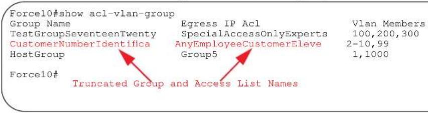
Figure 10-2 shows the table style display when using the show acl-vlan-group group-name option. Note that the access list name is truncated.
Figure 10-2. Command Example: show acl-vlan-group group-name

Figure 10-2 shows the line-by-line style display when using the show acl-vlan-group detail option. Note that no group or access list names are truncated
Figure 10-3. Command Example: show acl-vlan-group detail
| Force10#show acl-vlan-group detail |
| Group Name : TestGroupSeventeenTwenty Egress IP Acl : SpecialAccessOnlyExpertsAllowed Vlan Members : 100,200,300 |
| Group Name : CustomerNumberIdentificationEleven Egress IP Acl : AnyEmployeeCustomerElevenGrantedAccess Vlan Members : 2-10,99 |
| Group Name : HostGroup Egress IP Acl : Group5 Vlan Members : 1,1000 Force10# |
show acl-vlan-group detail
E Display all the ACL VLAN Groups or display a specific ACL VLAN Group by name. The output is show in a line-by-line format to display the names in their entirety.
Syntax show acl-vlan-group detail
Defaults No default behavior or values
Command Modes EXEC
EXEC Privilege
Command History
Version 7.8.1.0 Introduced on E-Series
Usage Notes
The output for this command is shown in a line-by-line format. This allows the ACL-VLAN-Group names (or the Access List Group Names) to display in their entirety.
Example
Figure 10-4. Command Example: show acl-clan-group
Force10(conf-acl-vl-grp)#show config
!
acl-vlan-group group1
description Acl Vlan Group1
member vlan 1-10,400-410,500
ip access-group acl1 out implicit-permit
Force10#
show config
E Display the current configuration of the ACL VLAN group.
Syntax show config
Defaults No default behavior or values
Command Modes
EXEC
Command History
Version 6.3.1.0 Introduced on E-Series
Example
Figure 10-5. show config Command Example
Force10(conf-acl-vl-grp)#show config
!
acl-vlan-group group1
description Acl Vlan Group1
member vlan 1-10,400-410,500
ip access-group acl1 out implicit-permit
Force10#
show running config acl-vlan-group
E Display the running configuration of all or a given ACL VLAN Group.
Syntax show running config acl-vlan-group group name
Parameters
group name
Display only the ACL VLAN Group that is specified. The group name can be up to 140 characters
Defaults
No default behavior or values
Command Modes
EXEC
Command History
Version 7.8.1.0 Increased name string to accept up to 140 characters. Prior to 7.8.1.0, names are up to 16 characters long.
Version 6.3.1.0 Introduced on E-Series
Example
Figure 10-6. show running-config acl-vlan-group Command Example Output
Force10#show running-config acl-vlan-group
!
acl-vlan-group group1
description Acl Vlan Group1
member vlan 1-10,400-410,500
ip access-group acl1 out implicit-permit
!
acl-vlan-group group2
member vlan 20
ip access-group acl2 out
Force10#
Force10#show running-config acl-vlan-group group1
!
acl-vlan-group group1
description Acl Vlan Group1
member vlan 1-10,400-410,500
ip access-group acl1 out implicit-permit
Force10#
Bidirectional Forwarding Detection (BFD)
Overview
Bidirectional Forwarding Detection (BFD) is a detection protocol that provides fast forwarding path failure detection. The FTOS implementation is based on the standards specified in the IETF Draft draft-ietf-bfd-base-03 and supports BFD on all Layer 3 physical interfaces including VLAN interfaces and port-channels.
BFD is supported on the C-Series and E-Series, where indicated by the C and E characters under command headings.
BFD is supported on E-Series ExaScale with FTOS 8.2.1.0 and later.
Commands
- bfd all-neighbors
- bfd disable
- bfd enable (Configuration)
- bfd enable (Interface)
- bfd interval
- bfd neighbor
- bfd protocol-liveness
- clear bfd counters
- debug bfd
- ip route bfd
- isis bfd all-neighbors
- neighbor bfd
- neighbor bfd disable
• show bfd counters
• show bfd neighbors
• vrrp bfd
bfd all-neighbors

S4810
Enable BFD sessions with all neighbors discovered by Layer 3 protocols IS-IS, OSPF, or BGP on router interfaces, and (optionally) reconfigure the default timer values.
Syntax
Parameters
bfd all-neighbors [interval interval min_rx min_rx multiplier value role {active | passive}]
| interval milliseconds | (OPTIONAL) Enter this keyword to specify non-default BFD session parameters beginning with the transmission interval.Range:50-1000Default:100 |
| min_rx milliseconds | Enter this keyword to specify the minimum rate at which the local system would like to receive control packets from the remote system.Range:50-100Default:100 |
| multiplier value | Enter this keyword to specify the number of packets that must be missed in order to declare a session down.Range:3-50Default:3 |
| role [active | passive] | Enter the role that the local system assumes:Active—The active system initiates the BFD session. Both systems can be active for the same session.Passive—The passive system does not initiate a session. It only responds to a request for session initialization from the active system.Default: Active |
Defaults
Command Modes
See Parameters
ROUTER OSPF
ROUTER BGP
ROUTER ISIS (Not available on C-Series)
Command History
Version 8.4.2.5 BFD for BGP was introduced on the C-Series and E-Series TeraScale.
| Version 8.3.8.0 BFD for BGP was introduced on the S4810. |
| Version 8.4.1.3 BFD for BGP was introduced on the E-Series ExaScale. |
| Version 8.2.1.0 BFD for OSPF and ISIS introduced on the E-Series ExaScale. |
| Version 7.6.1.0 BFD for OSPF introduced on the C-Series. |
| Version 7.5.1.0 BFD for ISIS introduced on the E-Series. |
| Version 7.4.1.0 BFD for OSPF introduced on the E-Series. |
Usage Information
All neighbors inherit the timer values configured with the bfd all-neighbors command except in the following cases:
- Timer values configured with the isis bfd all-neighbors command in INTERFACE mode override timer values configured with the bfd all-neighbors command. Likewise, using the no bfd all-neighbors command does not disable BFD on an interface if BFD is explicitly enabled using the command isis bfd all-neighbors.
Related Commands
- Neighbors that have been explicitly enabled or disabled for a BFD session with the bfd neighbor or neighbor bfd disable commands in ROUTER BGP mode do not inherit the global BFD enable/disable values configured with the bfd all-neighbors command or configured for the peer group to which a neighbor belongs. The neighbors inherit only the global timer values (configured with the bfd all-neighbors command).
show bfd neighbors Display BFD neighbor information on all interfaces or a specified interface.
bfd neighbor Explicitly enable a BFD session with a BGP neighbor or a BGP peer group.
neighbor bfd disable Explicitly disable a BFD session with a BGP neighbor or a BGP peer group.
bfd disable

Disable BFD on all interfaces.
Syntax
bfd disable
Re-enable BFD using the command no bfd disable.
Defaults
BFD is disabled by default.
Command Modes
INTERFACE VRRP
Command History
Version 8.2.1.0 Introduced on E-Series ExaScale
Version 7.6.1.0 Introduced on C-Series
Version 7.5.1.0 Introduced on E-Series
bfd enable (Configuration)

Enable BFD on all interfaces.
Syntax
bfd enable
Disable BFD using the no bfd enable command.
Defaults
BFD is disabled by default.
Command Modes
CONFIGURATION
Command History
Version 8.2.1.0 Introduced on E-Series ExaScale
Version 7.6.1.0 Introduced on C-Series
Version 7.4.1.0 Introduced on E-Series
bfd enable (Interface)

Enable BFD on an interface.
Syntax
bfd enable
Defaults
BFD is enabled on all interfaces when you enable BFD from CONFIGURATION mode.
Command Modes
INTERFACE
Command History
Version 8.2.1.0 Introduced on E-Series ExaScale
Version 7.6.1.0 Introduced on C-Series
Version 7.4.1.0 Introduced on E-Series
bfd interval

Specify non-default BFD session parameters beginning with the transmission interval.
Syntax
bfd interval interval min\_rx min\_rx multiplier value role {active | passive}
Parameters
| interval milliseconds | Enter this keyword to specify non-default BFD session parameters beginning with the transmission interval. Range:50-1000 Default:100 |
| min_rx milliseconds | Enter this keyword to specify the minimum rate at which the local system would like to receive control packets from the remote system. Range:50-100 Default:100 |
| multiplier value | Enter this keyword to specify the number of packets that must be missed in order to declare a session down. Range:3-50 Default:3 |
| role [active | passive] | Enter the role that the local system assumes:Active—The active system initiates the BFD session. Both systems can be active for the same session.Passive—The passive system does not initiate a session. It only responds to a request for session initialization from the active system. Default: Active |
Defaults
See Parameters
Command Modes
INTERFACE
Command History
Version 8.2.1.0 Introduced on E-Series ExaScale
Version 7.6.1.0 Introduced on C-Series
Version 7.4.1.0 Introduced on E-Series
Example
Figure 11-1. bfd interval Command Example
Force10(conf-if-gi-0/3)#bfd interval 250 min_rx 300 multiplier 4 role passive Force10(conf-if-gi-0/3)#
bfd neighbor

Establish a BFD session with a neighbor.
Syntax
bfd neighbor ip-address
Parameters
ip-address
Enter the IP address of the neighbor in dotted decimal format (A.B.C.D).
Defaults
None
Command Modes
INTERFACE
Command History
Version 8.2.1.0 Introduced on E-Series ExaScale
Version 7.6.1.0 Introduced on C-Series
Version 7.5.1.0 Added support for VLAN and port-channel interfaces on E-Series.
Version 7.4.1.0 Introduced on E-Series
Related Commands
show bfd neighbors Display BFD neighbor information on all interfaces or a specified interface.
bfd protocol-liveness

Enable the BFD protocol liveness feature.
Syntax
bfd protocol-liveness
Defaults
Disabled
Command Modes
CONFIGURATION
Command History
Version 7.4.1.0 Introduced on E-Series
Usage Information
Protocol Liveness is a feature that notifies the BFD Manager when a client protocol (e.g OSPF, ISIS) is disabled. When a client is disabled, all BFD sessions for that protocol are torn down. Neighbors on the remote system receive an Admin Down control packet and are placed in the Down state. Peer routers might take corrective action by choosing alternative paths for the routes that originally pointed to this router.
clear bfd counters

Clear all BFD counters, or counters for a particular interface.
Syntax
clear bfd counters [interface]
| Parameters | interface | (OPTIONAL) Enter one of the following keywords and slot/port or number information:For a 1-Gigabit Ethernet interface, enter the keyword followed by the slot/port information.For a 10-Gigabit Ethernet interface, enter the keyword followed by the slot/port information.For a SONET interface, enter the keyword sonet followed by the slot/port information.For a port-channel interface, enter the keyword port-channel followed by a number:C-Series and S-Series Range: 1-128E-Series Range: 1 to 32 for EtherScale, 1 to 255 for TeraScale, and 1 to 512 for ExaScaleFor VLAN interfaces, enter the keyword vlan followed by a number from 1 to 4094. For ExaScale VLAN interfaces, the range is 1-2730 (VLAN IDs can be 0-4093). |
| Defaults | None | |
| Command Modes | EXEC Privilege | |
| Command History | Version 8.2.1.0 Introduced on E-Series ExaScale | |
| Version 7.7.1.0 Introduced on C-Series | ||
| Version 7.5.1.0 Added support for VLAN and port-channel interfaces on E-Series | ||
| Version 7.4.1.0 Introduced on E-Series | ||
| Related Commands | show bfd counters Display BFD counter information. | |
Syntax
debug bfd {detail | event | packet} {all | interface} [mode] [count number]
Parameters
| detail | (OPTIONAL) Enter this keyword to display detailed information about BFD packets. |
| event | (OPTIONAL) Enter this keyword to display information about BFD state. The mode option is not available with this option. |
| packet | (OPTIONAL) Enter the keyword packet to display brief information about control packets. |
| all | Enter this keyword to enable debugging on all interfaces. The count option is not available with this option. |
| interface | Enter one of the following keywords and slot/port or number information:For a 1-Gigabit Ethernet interface, enter the keyword gigabitethernet followed by the slot/port information.For a 10-Gigabit Ethernet interface, enter the keyword tengigabitethernet followed by the slot/port information.For a SONET interface, enter the keyword sonet followed by the slot/port information.For a port-channel interface, enter the keyword port-channel followed by a number:C-Series and S-Series Range: 1-128E-Series Range: 1 to 32 for EtherScale, 1 to 255 for TeraScale, and 1 to 512 for ExaScaleFor VLAN interfaces, enter the keyword vlan followed by a number from 1 to 4094. For ExaScale VLAN interfaces, the range is 1-2730 (VLAN IDs can be 0-4093). |
| mode | (OPTIONAL) Enter one of the following debug transmission modes:Enter the keyword both to display information for both received and sent packets.Enter the keyword rx to display information for received packets.Enter the keyword tx to display information for sent packets.Default: both |
| count number | (OPTIONAL) Enter this keyword followed by the number of debug messages to display.Range: 1-65534Default: Infinite—that is, if a count number is not specified an infinite number of debug messages will display. |
Defaults
Disabled
Command Modes
EXEC Privilege
Command History
Version 8.2.1.0 Introduced on E-Series ExaScale
Version 7.6.1.0 Introduced on C-Series
Version 7.5.1.0 Added support for VLAN and port-channel interfaces on E-Series
Version 7.4.1.0 Introduced on E-Series
Usage Information
Since BFD can potentially transmit 20 packets per interface, debugging information should be restricted.
ip route bfd

Enable BFD for all neighbors configured through static routes.
Syntax
ip route bfd [interval interval min_rx min_rx multiplier value role {active | passive}]
| Parameters | interval milliseconds | (OPTIONAL) Enter this keyword to specify non-default BFD session parameters beginning with the transmission interval.Range:50-1000Default:100 |
| min_rx milliseconds | Enter this keyword to specify the minimum rate at which the local system would like to receive control packets from the remote system.Range:50-100Default:100 | |
| multiplier value | Enter this keyword to specify the number of packets that must be missed in order to declare a session down.Range:3-50Default:3 | |
| role [active | passive] | Enter the role that the local system assumes:Active—The active system initiates the BFD session. Both systems can be active for the same session.Passive—The passive system does not initiate a session. It only responds to a request for session initialization from the active system.Default: Active | |
| Defaults | See Parameters | |
| Command Modes | CONFIGURATION | |
| Command History | Version 8.2.1.0 Introduced on E-Series ExaScale | |
| Version 7.6.1.0 Introduced on C-Series | ||
| Version 7.4.1.0 Introduced on E-Series | ||
| Related Commands | show bfd neighbors Display BFD neighbor information on all interfaces or a specified interface. | |
isis bfd all-neighbors

Enable BFD on all IS-IS neighbors discovered on an interface.
Syntax
isis bfd all-neighbors [disable | [interval interval min_rx min_rx multiplier value role {active | passive}]]
Parameters
| disable | (OPTIONAL) Enter the keyword disable to disable BFD on this interface. |
| interval milliseconds | (OPTIONAL) Enter this keyword to specify non-default BFD session parameters beginning with the transmission interval.Range:50-1000Default:100 |
| min_rx milliseconds | Enter this keyword to specify the minimum rate at which the local system would like to receive control packets from the remote system. Range:50-100 Default:100 | |
| multiplier value | Enter this keyword to specify the number of packets that must be missed in order to declare a session down. Range:3-50 Default:3 | |
| role [active | passive] | Enter the role that the local system assumes: • Active—The active system initiates the BFD session. Both systems can be active for the same session. • Passive—The passive system does not initiate a session. It only responds to a request for session initialization from the active system. Default: Active | |
| Defaults | See Parameters | |
| Command Modes | INTERFACE | |
| Command History | Version 8.2.1.0 Introduced on E-Series ExaScale | |
| Version 7.5.1.0 Introduced on E-Series | ||
| Usage Information | This command provides the flexibility to fine tune the timer values based on individual interface needs when ISIS BFD is configured in CONFIGURATION mode. Any timer values specified with this command override timers set using the command bfd all-neighbors. Using the no form of this command will not disable BFD if BFD is configured in CONFIGURATION mode. Use the keyword disable to disable BFD on a specific interface while BFD is configured in from CONFIGURATION mode. | |
neighbor bfd

S4810
Explicitly enable a BFD session with a BGP neighbor or a BGP peer group.
Syntax
neighbor {ip-address | peer-group-name} bfd
Parameters
| ip-address | Enter the IP address of the BGP neighbor that you want to explicitly enable for BFD sessions in dotted decimal format (A.B.C.D). |
| peer-group-name | Enter the name of the peer group that you want to explicitly enable for BFD sessions. |
| None | |
| ROUTER BGP | |
| Version 8.4.2.5 Introduced on the C-Series and E-Series TeraScale. | |
| Version 8.3.8.0 Introduced on the S4810. | |
| Version 8.4.1.3 Introduced on the E-Series ExaScale. | |
Defaults
Command Modes
Command History
| Usage Information | When you enable a BFD session with a specified BGP neighbor or peer group using the bfd neighbor command, the default BFD session parameters are used (interval: 100 milliseconds, min_rx: 100 milliseconds, multiplier: 3 packets, and role: active) if no parameters have been specified with the bfd all-neighbors command. |
| When you explicitly enable a BGP neighbor for a BFD session with the bfd neighbor command:The neighbor does not inherit the global BFD enable values configured with the bfd all-neighbors command or configured for the peer group to which the neighbor belongs.The neighbor only inherits the global timer values configured with the bfd all-neighbors command: interval, min_rx, and multiplier. | |
| Related Commands | bfd all-neighbors Enable BFD sessions with all neighbors discovered by Layer 3 protocols. |
| neighbor bfd disable Explicitly disable a BFD session with a BGP neighbor or a BGP peer group. | |
| show bfd neighbors Display BFD neighbor information on all interfaces or a specified interface. |
neighbor bfd disable

S4810
Explicitly disable a BFD session with a BGP neighbor or a BGP peer group.
Syntax
neighbor {ip-address | peer-group-name} bfd disable
| Parameters | ip-address | Enter the IP address of the BGP neighbor that you want to explicitly disable for BFD sessions in dotted decimal format (A.B.C.D). |
| peer-group-name | Enter the name of the peer group that you want to explicitly disable for BFD sessions. | |
| Defaults | None | |
| Command Modes | ROUTER BGP | |
| Command History | Version 8.4.2.5 Introduced on the C-Series and E-Series TeraScale. | |
| Version 8.3.8.0 Introduced on the S4810. | ||
| Version 8.3.7.0 Introduced on the S4810. | ||
| Version 8.4.1.3 Introduced on the E-Series ExaScale. | ||
| Usage Information | When you explicitly disable a BGP neighbor for a BFD session with theneighbor bfd disablecommand, the neighbor does not inherit the global BFD values configured with thebfd all-neighborscommand or configured for the peer group to which the neighbor belongs.When you remove the disabled state of a BFD for BGP session with a specified neighbor by entering theno neighbor bfd disablecommand, the BGP neighbor uses the BFD session parameters globallyconfigured with thebfd all-neighborscommand or configured for the peer group to which the neighborbelongs. | |
| Related Commands | bfd all-neighbors Enable BFD sessions with all neighbors discovered by Layer 3 protocols. | |
| bfd neighbor Explicitly enable a BFD session with a BGP neighbor or a BGP peer group. | ||
| show bfd neighbors Display BFD neighbor information on all interfaces or a specified interface. | ||
show bfd counters

S4810
Display BFD counter information.
Syntax
show bfd counters [bgp | isis | ospf | vrrp | static-route] [interface]
Parameters
| interface | Enter one of the following keywords and slot/port or number information:For a 1-Gigabit Ethernet interface, enter the keywordgigabitethernetfollowed by the slot/port information.For a 10-Gigabit Ethernet interface, enter the keywordtengigabitethernetfollowed by the slot/port information.For a SONET interface, enter the keywordsonetfollowed by the slot/port information.For a port-channel interface, enter the keywordport-channelfollowed by a number:C-Series and S-Series Range: 1-128E-Series Range: 1 to 32 for EtherScale, 1 to 255 for TeraScale, and 1 to 512 for ExaScaleFor VLAN interfaces, enter the keywordvlanfollowed by a number from 1 to 4094. For ExaScale VLAN interfaces, the range is 1-2730 (VLAN IDs can be 0-4093). |
| bgp | (OPTIONAL) Enter this keyword to display counter information for BFD sessions established with BGP neighbors. |
| isis | (OPTIONAL) Enter this keyword to display counter information for BFD sessions established with ISIS neighbors. This option is not available on C-Series. |
| ospf | (OPTIONAL) Enter this keyword to display counter information for BFD sessions established with OSPF neighbors. |
| static-route | (OPTIONAL) Enter this keyword to display counter information for BFD sessions established with ISIS neighbors. |
| vrrp | (OPTIONAL) Enter this keyword to display counter information for BFD sessions established with VRRP neighbors. |
Defaults
None
Command Modes
EXEC
EXEC Privilege
Command History
Version 8.4.2.5 Added support for BFD for BGP on the C-Series and E-Series TeraScale.
Version 8.3.7.0 Added support for BFD for BGP on the S4810.
Version 8.3.8.0 Added support for BFD for BGP on the S4810.
Version 8.4.1.3 Added support for BFD for BGP on the E-Series ExaScale.
Version 8.2.1.0 Introduced on E-Series ExaScale
Version 7.7.1.0 Introduced on C-Series
Version 7.5.1.0 Added support for BFD for VLAN and port-channel interfaces, ISIS, and VRRP on E-Series.
Version 7.4.1.0 Introduced BFD on physical ports, static routes, and OSPF on E-Series.
Example
Figure 11-2. show bfd counters Command Example
| Force10#show bfd counters | ||
| Interface | Tx | Rx |
| GigabitEthernet 1/3 | 522 | 625 |
| Force10# | ||
show bfd neighbors

S4810
Display BFD neighbor information on all interfaces or a specified interface.
Syntax
show bfd neighbors interface [detail]
| Parameters | interface | Enter one of the following keywords and slot/port or number information:For a 1-Gigabit Ethernet interface, enter the keywordgigabitethernetfollowed by the slot/port information.For a 10-Gigabit Ethernet interface, enter the keywordtengigabitethernetfollowed by the slot/port information.For a SONET interface, enter the keywordsonetfollowed by the slot/port information.For a Port Channel interface, enter the keywordport-channelfollowed by a number:C-Series and S-Series Range: 1-128E-Series Range: 1 to 32 for EtherScale, 1 to 255 for TeraScale, and 1 to 512 for ExaScaleFor VLAN interfaces, enter the keywordvlanfollowed by a number from 1 to 4094. For ExaScale VLAN interfaces, the range is 1-2730 (VLAN IDs can be 0-4093). |
| detail | (OPTIONAL) Enter the keyworddetailto view detailed information about BFD neighbors. | |
| Defaults | None | |
| hand Modes | EXEC | |
| EXEC Privilege | ||
| Command History | Version 8.4.2.5 Added support for BFD for BGP on the C-Series and E-Series TeraScale. | |
| Version 8.3.7.0 Added support for BFD for BGP on the S4810. | ||
| Version 8.3.8.0 Added support for BFD for BGP on the S4810. | ||
| Version 8.4.1.3 Added support for BFD for BGP on the E-Series ExaScale. | ||
| Version 8.2.1.0 Introduced on E-Series ExaScale | ||
| Version 7.6.1.0 Introduced on C-Series | ||
| Version 7.5.1.0 Added BFD on VLAN and port-channel interfaces on E-Series | ||
| Version 7.4.1.0 Introduced BFD on physical ports on E-Series | ||
Example
Figure 11-3. show bfd neighbors Command
| Force10#show bfd neighbors | |||||||
| * | - Active session role | ||||||
| Ad Dn | - Admin Down | ||||||
| C | - CLI | ||||||
| I | - ISIS | ||||||
| O | - OSPF | ||||||
| R | - Static Route (RTM) | ||||||
| LocalAddr | RemoteAddr | Interface | State | Rx-int | Tx-int | Mult | Clients |
| * 10.1.3.2 | 10.1.3.1 | Gi 1/3 | Up | 300 | 250 | 3 | C |
| Force10# | |||||||
Example
Figure 11-4. show bfd neighbors detail Command Example
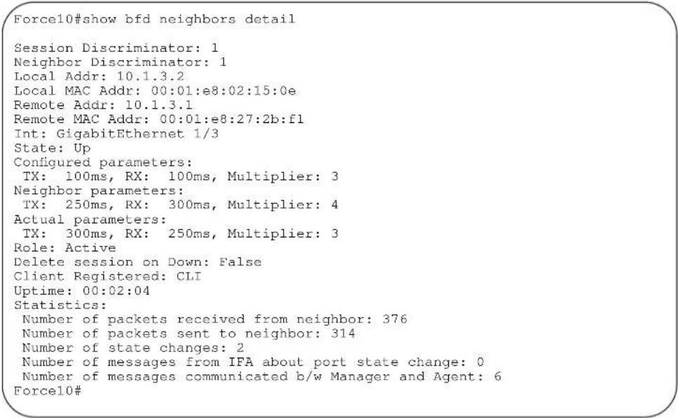
Related Commands
bfd neighbor Establish a BFD session with a neighbor.
bfd all-neighbors Establish BFD sessions with all neighbors discovered by the IS-IS protocol or OSPF protocol out of all interfaces.
vrrp bfd

Establish a VRRP BFD session.
Syntax
vrrp bfd {all-neighbors | neighbor ip-address} [interval interval min_rx min_rx multiplier value role {active | passive}]
Parameters
| all-neighbors | Establish BFD sessions with all BFD neighbors on an interface. |
| neighbor ip-address | Enter the IP address of the BFD neighbor. |
| interval milliseconds | (OPTIONAL) Enter this keyword to specify non-default BFD session parameters beginning with the transmission interval.Range:50-1000Default:100 |
| min_rx milliseconds | Enter this keyword to specify the minimum rate at which the local system would like to receive control packets from the remote system.Range:50-100Default:100 |
| multiplier | Enter this keyword to specify the number of packets that must be missed in order to declare a session down.Range:3-50Default:3 |
| role [active | passive] | Enter the role that the local system assumes:Active—The active system initiates the BFD session. Both systems can be active for the same session.Passive—The passive system does not initiate a session. It only responds to a request for session initialization from the active system.Default: Active |
Defaults
See Parameters.
Command Modes
INTERFACE
Command History
Version 8.2.1.0 Introduced on E-Series ExaScale
Version 7.6.1.0 Introduced on C-Series
Version 7.5.1.0 Introduced on E-Series
Border Gateway Protocol IPv4 (BGPv4)
Overview
BGPv4 is supported as shown in the following table.
| FTOS version Platform support | |
| 8.1.1.0 E-Series ExaScale |  |
| 7.8.1.0 S-Series | [GBTC] |
| 7.7.1.0. C-Series |  |
| pre-7.7.1.0 E-Series TeraScale |  |
For detailed information on configuring BGP, refer to the BGP chapter in the FTOS Configuration Guide.
This chapter contains the following sections:
- BGPv4 Commands
- MBGP Commands
• BGP Extended Communities (RFC 4360)
BGPv4 Commands
Border Gateway Protocol (BGP) is an external gateway protocol that transmits interdomain routing information within and between Autonomous Systems (AS). BGP version 4 (BGPv4) supports Classless InterDomain Routing (CIDR) and the aggregation of routes and AS paths. Basically, two routers (called neighbors or peers) exchange information including full routing tables and periodically send messages to update those routing tables.

Note: FTOS Version 7.7.1 supports 2-Byte (16-bit) and 4-Byte (32-bit) format for Autonomous System Numbers (ASNs), where the 2-Byte format is 1-65535, the 4-Byte format is 1-4294967295.
Note: FTOS Version 8.3.1.0 supports Dotted format as well as the Traditional Plain format for AS Numbers. The dot format is displayed when using the show ip bgp commands. To determine the comparable dot format for an ASN from a traditional format, use ASN/65536.ASN%65536.
For more information about using the 2 or 4-Byte format, refer to the FTOS Configuration Guide.
The following commands enable you to configure and enable BGP.
- address-family
- aggregate-address
• bgp always-compare-med - bgp asnotation
• bgp bestpath as-path ignore
• bgp bestpath med confed
• bgp bestpath med missing-as-best
• bgp bestpath router-id ignore
• bgp client-to-client reflection - bgp cluster-id
• bgp confederation identifier
• bgp confederation peers - bgp dampening
- bgp default local-preference
- bgp enforce-first-as
• bgp fast-external-fallover - bgp four-octet-as-support
- bgp graceful-restart
• bgp log-neighbor-changes
• bgp non-deterministic-med
• bgp recursive-bgp-next-hop
• bgp regex-eval-optz-disable
• bgp retain-ibgp-nexthop - bgp router-id
- bgp soft-reconfig-backup
• capture bgp-pdu neighbor
• capture bgp-pdu max-buffer-size - clear ip bgp ipv4 unicast soft
- clear ip bgp dampening
- clear ip bgp flap-statistics
- debug ip bgp
- debug ip bgp dampening
- debug ip bgp events
- debug ip bgp keepalives
- debug ip bgp notifications
- debug ip bgp updates
- default-metric
- description
- distance bgp
- maximum-paths
- neighbor activate
• neighbor advertisement-interval - neighbor advertisement-start
- neighbor allowas-in
- debug ip bgp ipv4 unicast soft-reconfiguration
- neighbor default-originate
- neighbor description
- neighbor distribute-list
- neighbor ebgp-multihop
- neighbor fall-over
- neighbor filter-list
- neighbor graceful-restart
- neighbor local-as
- neighbor maximum-prefix
- neighbor next-hop-self
- neighbor password
- neighbor peer-group (assigning peers)
- neighbor peer-group (creating group)
• neighbor peer-group passive - neighbor remote-as
- neighbor remove-private-as
- neighbor route-map
- neighbor route-reflector-client
- neighbor send-community
- neighbor shutdown
- neighbor soft-reconfiguration inbound
- neighbor timers
- neighbor update-source
- neighbor weight
- network
- network backdoor
- redistribute
- redistribute isis
- redistribute ospf
- router bgp
• show capture bgp-pdu neighbor
• show config
• show ip bgp
• show ip bgp cluster-list
• show ip bgp community
• show ip bgp community-list
• show ip bgp dampened-paths
• show ip bgp detail
• show ip bgp extcommunity-list
• show ip bgp filter-list
• show ip bgp flap-statistics
• show ip bgp inconsistent-as
• show ip bgp neighbors
• show ip bgp next-hop
• show ip bgp paths
• show ip bgp paths as-path
• show ip bgp paths community
• show ip bgp peer-group
• show ip bgp regexp
• show ip bgp summary
• show running-config bgp
- timers bgp
address-family

Enable the IPv4 multicast or the IPv6 address family.
Syntax
address-family [ipv4 multicast| ipv6unicast]
Parameters
| ipv4 multicast | Enter BGPv4 multicast mode. |
| ipv6 unicast | Enter BGPv6 mode. |
Defaults
Not configured.
Command Modes
ROUTER BGP
Command
Version 6.5.1.0 Introduced
aggregate-address

Summarize a range of prefixes to minimize the number of entries in the routing table.
Syntax
aggregate-address ip-address mask [advertise-map map-name] [as-set] [attribute-map map-name] [summary-only] [suppress-map map-name]
Parameters
| ip-address mask | Enter the IP address and mask of the route to be the aggregate address. Enter the IP address in dotted decimal format (A.B.C.D) and mask in /prefix format (/x). |
| advertise-map map-name | (OPTIONAL) Enter the keywordsadvertise-mapfollowed by the name of a configured route map to set filters for advertising an aggregate route. |
| as-set | (OPTIONAL) Enter the keywordas-setto generate path attribute information and include it in the aggregate.AS_SET includes AS_PATHand community information from the routes included in the aggregated route. |
| attribute-map map-name | (OPTIONAL) Enter the keywordsattribute-mapfollowed by the name of a configured route map to modify attributes of the aggregate, excluding AS_PATHand NEXT_HOP attributes. |
| summary-only | (OPTIONAL) Enter the keywordsummary-onlyto advertise only the aggregate address. Specific routes will not be advertised. |
| suppress-map map-name | (OPTIONAL) Enter the keywordssuppress-mapfollowed by the name of a configured route map to identify which more-specific routes in the aggregate are suppressed. |
Defaults
Not configured.
| Command Modes | ROUTER BGP ADDRESS FAMILY |
| ROUTER BGP ADDRESS FAMILY IPv6 | |
| Usage Information | At least one of the routes included in the aggregate address must be in the BGP routing table for the configured aggregate to become active. |
| Do not add the as-set parameter to the aggregate, if routes within the aggregate are constantly changing as the aggregate will flap to keep track of the changes in the AS_PATH. | |
| In route maps used in the suppress-map parameter, routes meeting the deny clause are not suppress; in other words, they are allowed. The opposite is true: routes meeting the permit clause are suppressed. | |
| If the route is injected via the network command, that route will still appear in the routing table if the summary-only parameter is configured in the aggregate-address command. | |
| The summary-only parameter suppresses all advertisements. If you want to suppress advertisements to only specific neighbors, use the neighbor distribute-list command. | |
| In the show ip bgp command, aggregates contain an ‘a’ in the first column and routes suppressed by the aggregate contain an ‘s’ in the first column. | |
| Command History | Version 7.8.1.0 Introduced support on S-Series |
| Version 7.7.1.0 Introduced support on C-Series |
bgp always-compare-med

Enables you to enable comparison of the MULTI_EXIT_DISC (MED) attributes in the paths from different external ASs.
Syntax bgp always-compare-med
To disable comparison of MED, enter no bgp always-compare-med.
Defaults Disabled (that is, the software only compares MEDs from neighbors within the same AS).
Command Modes ROUTER BGP
Usage Information Any update without a MED attribute is the least preferred route If you enable this command, use the clear ip bgp ipv4 unicast soft * command to recompute the best path.
Command History
Version 8.2.1.0 Introduced command
Version 7.7.1.0 Introduced support on C-Series
bgp asnotation

Enables you to implement a method for AS Number representation in the CLI.
Syntax
bgp asnotation [asplain | asdot+ | asdot]
To disable a dot or dot+ representation and return to ASPLAIN, enter no bgp asnotation.
Defaults
asplain
Command Modes
ROUTER BGP
Usage Information
You must enable bgp four-octet-as-support before enabling this feature. If you disable four-octet-support after using dot or dot+ format, the AS Numbers revert to asplain text.
When you apply an annotation, it is reflected in the running-configuration. If you change the notation type, the running-config is updated dynamically and the new notation is shown.
Related Commands
bgp four-octet-as-support Enable 4-Byte support for the BGP process
Command History
Version 8.3.1.0 Introduced Dynamic Application of AS Notation changes
Version 8.2.1.0 Introduced
Example
Figure 12-1. Dynamic changes of the bgp asnotation command in the running config
(conf)#router bgp 1
(conf-router_bgp)#bgp asnotation asdot
(conf-router_bgp)#ex
(conf)#do show run | grep bgp

router bgp 1
bgp four-octet-as-support
bgp asnotation asdot

(conf)#router bgp 1
(conf-router_bgp)#bgp asnotation asdot+
(conf-router_bgp)#ex

(conf)#do show run | grep bgp
router bgp 1
bgp four-octet-as-support
bgp asnotation asdot+

(conf)#router bgp 1
(conf-router_bgp)#bgp asnotation asplain
(conf-router_bgp)#ex
(conf)#do show run | grep bgp
router bgp 1
bgp four-octet-as-support

(conf)#
bgp bestpath as-path ignore

Ignore the AS PATH in BGP best path calculations.
Syntax
bgp bestpath as-path ignore
To return to the default, enter no bgp bestpath as-path ignore.
Defaults
Disabled (that is, the software considers the AS_PATH when choosing a route as best).
Command Modes
ROUTER BGP
Usage Information
If you enable this command, use the clear ip bgp ipv4 unicast soft * command to recompute the best path.
Command History
Version 7.8.1.0 Introduced support on S-Series
Version 7.7.1.0 Introduced support on C-Series
bgp bestpath med confed

Enable MULTI_EXIT_DISC (MED) attribute comparison on paths learned from BGP confederations.
Syntax
bgp bestpath med confed
To disable MED comparison on BGP confederation paths, enter no bgp bestpath med confed.
Defaults
Disabled
Command Modes
ROUTER BGP
Usage Information
The software compares the MEDs only if the path contains no external autonomous system numbers. If you enable this command, use the clear ip bgp ipv4 unicast soft * command to recompute the best path.
Command History
Version 7.8.1.0 Introduced support on S-Series
Version 7.7.1.0 Introduced support on C-Series
bgp bestpath med missing-as-best

During path selection, indicate preference to paths with missing MED (MULTI_EXIT_DISC) over those paths with an advertised MED attribute.
Syntax
bgp bestpath med missing-as-best
To return to the default selection, use the no bgp bestpath med missing-as-best command.
Defaults
Disabled
Command Modes
ROUTER BGP
| Usage Information | The MED is a 4-Byte unsigned integer value and the default behavior is to assume a missing MED as 4294967295. This command causes a missing MED to be treated as 0. During the path selection, paths with a lower MED are preferred over those with a higher MED. |
| Command History | Version 7.8.1.0 Introduced support on S-Series |
| Version 7.7.1.0 Introduced support on C-Series | |
| Version 6.3.1.0 Introduced |
bgp bestpath router-id ignore

Do not compare router-id information for external paths during best path selection.
Syntax
bgp bestpath router-id ignore
To return to the default selection, use the no bgp bestpath router-id ignore command.
Defaults
Disabled
Command Modes
ROUTER BGP
Usage Information
Configuring this option will retain the current best-path. When the session is subsequently reset, the oldest received path will be chosen as the best-path.
Command History
Version 8.3.1.0 Introduced
bgp client-to-client reflection

Enables you to enable route reflection between clients in a cluster.
Syntax
bgp client-to-client reflection
To disable client-to-client reflection, enter no bgp client-to-client reflection.
Defaults
Enabled when a route reflector is configured.
Command Modes
ROUTER BGP
Usage Information
Route reflection to clients is not necessary if all client routers are fully meshed.
Related Commands
bgp cluster-id Assign ID to a BGP cluster with two or more route reflectors.
neighbor route-reflector-client Configure a route reflector and clients.
Command History
Version 7.8.1.0 Introduced support on S-Series
Version 7.7.1.0 Introduced support on C-Series
bgp cluster-id
| Syntax | Assign a cluster ID to a BGP cluster with more than one route reflector. | |
| bgp cluster-id {ip-address | number} | ||
| To delete a cluster ID, use the no bgp cluster-id {ip-address | number} command. | ||
| Parameters | ip-address Enter an IP address as the route reflector cluster ID. | |
| number | Enter a route reflector cluster ID as a number from 1 to 4294967295. | |
| Defaults | Not configured. | |
| Command Modes | ROUTER BGP | |
| Usage Information | When a BGP cluster contains only one route reflector, the cluster ID is the route reflector's router ID. For redundancy, a BGP cluster may contain two or more route reflectors and you assign a cluster ID with the bgp cluster-id command. Without a cluster ID, the route reflector cannot recognize route updates from the other route reflectors within the cluster. | |
| The default format for displaying the cluster-id is dotted decimal, but if you enter the cluster-id as an integer, it will be displayed as an integer. | ||
| Related Commands | bgp client-to-client reflection Enable route reflection between route reflector and clients. | |
| neighbor route-reflector-client Configure a route reflector and clients. | ||
| show ip bgp cluster-list View paths with a cluster ID. | ||
| Command History | Version 7.8.1.0 Introduced support on S-Series | |
| Version 7.7.1.0 Introduced support on C-Series | ||
bgp confederation identifier
| Syntax | bgp confederation identifier as-numberTo delete a BGP confederation identifier, use the no bgp confederation identifier as-number command. | |
| Parameters | as-number | Enter the AS number.Range: 0-65535 (2-Byte) or1-4294967295 (4-Byte) or0.1-65535.65535 (Dotted format) |
| Defaults | Not configured. | |
| Command Modes | ROUTER BGP | |
| Usage Information | You must configure your system to accept 4-Byte formats before entering a 4-Byte AS Number. All the routers in the Confederation must be 4 or 2-Byte identified routers. You cannot mix them. | |
The autonomous systems configured in this command are visible to the EBGP neighbors. Each autonomous system is fully meshed and contains a few connections to other autonomous systems. The next hop, MED, and local preference information is preserved throughout the confederation.
FTOS accepts confederation EBGP peers without a LOCAL_PREF attribute. The software sends AS_CONFED_SET and accepts AS_CONFED_SET and AS_CONF_SEQ.
| Related Commands | bgp four-octet-as-support Enable 4-Byte support for the BGP process. |
| Command History | Version 7.8.1.0 Introduced support on S-Series |
| Version 7.7.1.0 Introduced support on C-SeriesAdded support for 4-Byte format |
bgp confederation peers

Specify the Autonomous Systems (ASs) that belong to the BGP confederation.
Syntax
bgp confederation peers as-number [...as-number]
To return to the default, enter no bgp confederation peers.
| Parameters | as-number | Enter the AS number.Range: 0-65535 (2-Byte) or1-4294967295 (4-Byte) or0.1-65535.65535 (Dotted format) |
| ...as-number | (OPTIONAL) Enter up to 16 confederation numbers.Range: 0-65535 (2-Byte) or1-4294967295 (4-Byte) or0.1-65535.65535 (Dotted format) | |
| Defaults | Not configured. | |
| Hand Modes | ROUTER BGP | |
| Usage Information | All the routers in the Confederation must be 4 or 2 byte identified routers. You cannot mix them.The Autonomous Systems configured in this command are visible to the EBGP neighbors. Each Autonomous System is fully meshed and contains a few connections to other Autonomous Systems.After specifying autonomous systems numbers for the BGP confederation, recycle the peers to update their configuration. | |
| Related Commands | bgp confederation identifier Configure a confederation ID. | |
| bgp four-octet-as-support Enable 4-Byte support for the BGP process. | ||
| Command History | Version 7.8.1.0 Introduced support on S-Series | |
| Version 7.7.1.0 Introduced support on C-SeriesAdded support for 4-Byte format | ||
bgp dampening

Enable BGP route dampening and configure the dampening parameters.
Syntax
bgp dampening [half-life reuse suppress max-suppress-time] [route-map map-name]
To disable route dampening, use the no bgp dampening [half-life reuse suppress max-suppress-time] [route-map map-name] command.
Parameters
| half-life | (OPTIONAL) Enter the number of minutes after which the Penalty is decreased. After the router assigns a Penalty of 1024 to a route, the Penalty is decreased by half after the half-life period expires.Range: 1 to 45.Default: 15 minutes |
| reuse | (OPTIONAL) Enter a number as the reuse value, which is compared to the flapping route's Penalty value. If the Penalty value is less than the reuse value, the flapping route is once again advertised (or no longer suppressed).Range: 1 to 20000.Default: 750 |
| suppress | (OPTIONAL) Enter a number as the suppress value, which is compared to the flapping route's Penalty value. If the Penalty value is greater than the suppress value, the flapping route is no longer advertised (that is, it is suppressed).Range: 1 to 20000.Default: 2000 |
| max-suppress-time | (OPTIONAL) Enter the maximum number of minutes a route can be suppressed. The default is four times the half-life value.Range: 1 to 255.Default: 60 minutes. |
| route-map map-name | (OPTIONAL) Enter the keyword route-map followed by the name of a configured route map.Only match commands in the configured route map are supported. |
Defaults
Disabled.
Command Modes
ROUTER-BGP-ADDRESS FAMILY
Usage Information
If you enter bgp dampening, the default values for half-life, reuse, suppress, and max-suppress-time are applied. The parameters are position-dependent, therefore, if you configure one parameter, you must configure the parameters in the order they appear in the CLI.
Related Commands
show ip bgp dampened-paths View the BGP paths
Command History
Version 7.8.1.0 Introduced support on S-Series
Version 7.7.1.0 Introduced support on C-Series
bgp default local-preference

Change the default local preference value for routes exchanged between internal BGP peers.
Syntax
bgp default local-preference value
To return to the default value, enter no bgp default local-preference.
| Parameters | value | Enter a number to assign to routes as the degree of preference for those routes. When routes are compared, the higher the degree of preference or local preference value, the more the route is preferred.Range: 0 to 4294967295Default: 100 |
| Defaults | 100 | |
| Command Modes | ROUTER BGP | |
| Usage Information | The bgp default local-preference command setting is applied by all routers within the AS. To set the local preference for a specific route, use the set local-preference command in the ROUTE-MAP mode. | |
| Related Commands | set local-preference Assign a local preference value for a specific route. | |
| Command History | Version 7.8.1.0 Introduced support on S-Series | |
| Version 7.7.1.0 Introduced on C-Series | ||
bgp enforce-first-as

Disable (or enable) enforce-first-as check for updates received from EBGP peers.
Syntax
bgp enforce-first-as
| To turn off the default, use theno bgp enforce-first-ascommand. | |
| Defaults | Enabled |
| Command Modes | ROUTER BGP |
| Usage Information | This is enabled by default, that is for all updates received from EBGP peers, BGP ensures that the first AS of the first AS segment is always the AS of the peer. If not, the update is dropped and a counter is incremented. Use theshow ip bgp neighborscommand to view the “failed enforce-first-as check counter. |
| If enforce-first-as is disabled, it can be viewed via theshow ip protocolscommand. | |
| Related Commands | show ip bgp neighborsView the information exchanged by BGP neighbors |
| show ip protocolsView Information on routing protocols. | |
| Command History | Version 7.8.1.0Introduced support on S-Series |
Version 7.7.1.0 Introduced support for C-Series
Version 7.4.1.0 Introduced
bgp fast-external-fallover

Enable the fast external fallover feature, which immediately resets the BGP session if a link to a directly connected external peer fails.
Syntax
bgp fast-external-fallover
To disable fast external fallover, enter no bgp fast-external-fallover.
Defaults
Enabled.
Command Modes
ROUTER BGP
Usage Information
The bgp fast-external-fallover command appears in the show config command output.
Command History
Version 7.8.1.0 Introduced support on S-Series
Version 7.7.1.0 Introduced support for C-Series
bgp four-octet-as-support

Enable 4-Byte support for the BGP process.
Syntax
bgp four-octet-as-support
To disable fast external fallover, enter no bgp four-octet-as-support.
Defaults
Disabled (supports 2-Byte format)
Command Modes
ROUTER BGP
Usage Information
Routers supporting 4-Byte ASNs advertise that function in the OPEN message. The behavior of a 4-Byte router will be slightly different depending on whether it is speaking to a 2-Byte router or a 4-Byte router.
When creating Confederations, all the routers in the Confederation must be 4 or 2 byte identified routers. You cannot mix them.
Where the 2-Byte format is 1-65535, the 4-Byte format is 1-4294967295. Both formats are accepted, and the advertisements will reflect the entered format.
For more information about using the 2 or 4-Byte format, refer to the FTOS Configuration Guide.
Command History
Version 7.8.1.0 Introduced support on S-Series
Version 7.7.1.0 Introduced command
Introduced support on C-Series
bgp graceful-restart

Enable graceful restart on a BGP neighbor, a BGP node, or designate a local router to support graceful restart as a receiver only.
Syntax
bgp graceful-restart [restart-time seconds] [stale-path-time seconds] [role receiver-only]
To return to the default, enter the no bgp graceful-restart command.
| Parameters | restart-time seconds | Enter the keyword restart-time followed by the maximum number of seconds needed to restart and bring-up all the peers. Range: 1 to 3600 seconds Default: 120 seconds |
| stale-path-time seconds | Enter the keyword stale-path-time followed by the maximum number of seconds to wait before restarting a peer's stale paths. Default: 360 seconds. | |
| role receiver-only | Enter the keyword role receiver-only to designate the local router to support graceful restart as a receiver only. | |
| Defaults | as above | |
| Command Modes | ROUTER-BGP | |
| Usage Information | This feature is advertised to BGP neighbors through a capability advertisement. In receiver only mode, BGP saves the advertised routes of peers that support this capability when they restart. | |
| BGP graceful restart is active only when the neighbor becomes established. Otherwise it is disabled. Graceful-restart applies to all neighbors with established adjacency. | ||
| Command History | Version 7.8.1.0 Introduced support on S-Series | |
| Version 7.7.1.0 Introduced support on C-Series | ||
bgp log-neighbor-changes

Enable logging of BGP neighbor resets.
Syntax
bgp log-neighbor-changes
To disable logging, enter no bgp log-neighbor-changes.
| Defaults | Enabled. |
| Command Modes | ROUTER BGP |
| Usage Information | Use theshow loggingcommand in the EXEC mode to view BGP neighbor resets.Thebgp log-neighbor-changescommand appears in theshow configcommand output. |
| Related Commands | show loggingView logging settings and system messages logged to the system. |
Command History
Version 7.8.1.0 Introduced support on S-Series
Version 7.7.1.0 Introduced support on C-Series
bgp non-deterministic-med

Compare MEDs of paths from different Autonomous Systems.
Syntax
bgp non-deterministic-med
To return to the default, enter no bgp non-deterministic-med.
Defaults
Disabled (that is, paths/routes for the same destination but from different ASs will not have their MEDs compared).
Command Modes
ROUTER BGP
Usage Information
In non-deterministic mode, paths are compared in the order in which they arrive. This method can lead to FTOS choosing different best paths from a set of paths, depending on the order in which they are received from the neighbors since MED may or may not get compared between adjacent paths. In deterministic mode (no bgp non-deterministic-med), FTOS compares MED between adjacent paths within an AS group since all paths in the AS group are from the same AS.
When you change the path selection from deterministic to non-deterministic, the path selection for existing paths remains deterministic until you enter clear ip bgp ipv4 unicast soft command to clear existing paths.
Command History
Version 7.8.1.0 Introduced support on S-Series
Version 7.7.1.0 Introduced support on C-Series
bgp recursive-bgp-next-hop

Enable next-hop resolution through other routes learned by BGP.
Syntax
bgp recursive-bgp-next-hop
To disable next-hop resolution, use the no bgp recursive-bgp-next-hop command.
Defaults
Enabled
Command Modes
ROUTER BGP
Usage Information
This command is a knob to disable BGP next-hop resolution via BGP learned routes. During the next-hop resolution, only the first route that the next-hop resolves through is verified for the route's protocol source and is checked if the route is learned from BGP or not.
The clear ip bgp command is required for this command to take effect and to keep the BGP database consistent. Execute the clear ip bgp command right after executing this command.
| Related Commands | clear ip bgp ipv4 unicast soft | Clear and reapply policies for IPv4 routes without resetting the TCP connection; that is, perform BGP soft reconfiguration. |
| Command History | ||
| Version 7.8.1.0 Introduced support on S-Series | ||
| Version 7.7.1.0 Introduced support on C-Series | ||
| Version 7.2.1.0 Introduced | ||
bgp regex-eval-optz-disable

Disables the Regex Performance engine that optimizes complex regular expression with BGP.
Syntax
bgp regex-eval-optz-disable
To re-enable optimization engine, use the no bgp regex-eval-optz-disable command.
Defaults
Enabled by default
Command Modes
ROUTER BGP (conf-router_bgp)
Usage Information
BGP uses regular expressions (regex) to filter route information. In particular, the use of regular expressions to filter routes based on AS-PATHs and communities is quite common. In a large scale configuration, filtering millions of routes based on regular expressions can be quite CPU intensive, as a regular expression evaluation involves generation and evaluation of complex finite state machines.
BGP policies, containing regular expressions to match as-path and communities, tend to use a lot of CPU processing time, which in turn affects the BGP routing convergence. Additionally, the show bgp commands, which are filtered through regular expressions, use up CPU cycles particularly with large databases. The Regex Engine Performance Enhancement feature optimizes the CPU usage by caching and reusing regular expression evaluation results. This caching and reuse may be at the expensive of RP1 processor memory.
Related Commands
show ip protocols View information on all routing protocols enabled and active on the E-Series.
Command History
Version 7.8.1.0 Introduced support on S-Series
Version 7.7.1.0 Introduced support on C-Series
Version 7.6.1.0 Introduced
Example
Figure 12-2. Command Example: no bgp regex-eval-optz-disable
(conf-router_bgp)#no bgp regex-eval-optz-disable
(conf-router_bgp)#do show ip protocols
Routing Protocol is "ospf 22222"
Router ID is 2.2.2.2
Area    Routing for Networks
51    10.10.10.0/00

Routing Protocol is "bgp 1"
Cluster Id is set to 10.10.10.0
Router Id is set to 10.10.10.0
Fast-external-fallover enabled
Regular expression evaluation optimization enabled
Capable of ROUTE_REFRESH
For Address Family IPv4 Unicast
BGP table version is 0, main routing table version 0
Distance: external 20 internal 200 local 200
(conf-router_bgp)#
bgp retain-ibgp-nexthop

BGP does not update the NEXT_HOP attribute if it is a Route-Reflector. Use this command to retain the NEXT_HOP attribute when advertising to internal BGP peer.
Syntax
bgp retain-ibgp-nexthop
Defaults
Disabled
Command Modes
ROUTER BGP
Command History
Version 8.4.1.0 Introduced on E-Series TeraScale, C-Series, and S-Series.
Version 8.3.1.2 Introduced on E-Series ExaScale.
bgp router-id

Assign a user-given ID to a BGP router.
Syntax
bgp router-id ip-address
To delete a user-assigned IP address, enter no bgp router-id.
Parameters
ip-address
Enter an IP address in dotted decimal format to reset only that BGP neighbor.
Defaults
The router ID is the highest IP address of the Loopback interface or, if no Loopback interfaces are configured, the highest IP address of a physical interface on the router.
Command Modes
ROUTER BGP
Usage Information
Peering sessions are reset when you change the router ID of a BGP router.
Command History
Version 7.8.1.0 Introduced support on S-Series
Version 7.7.1.0 Introduced support on C-Series
bgp soft-reconfig-backup

Use this command only when route-refresh is not negotiated between peers to avoid having a peer resend BGP updates.
Syntax
bgp soft-reconfig-backup
To return to the default setting, use the no bgp soft-reconfig-backup command.
Defaults
Off
Command Modes
ROUTER BGP
Usage Information
When soft-reconfiguration is enabled for a neighbor and the clear ip bgp soft in is executed, the update database stored in the router is replayed and updates are reevaluated. With this command, the replay and update process is triggered only if route-refresh request is not negotiated with the peer. If the request is indeed negotiated (upon execution of clear ip bgp soft in), then BGP sends a route-refresh request to the neighbor and receives all of the peer's updates.
Related Commands
clear ip bgp ipv4 unicast soft in
Activate inbound policies for IPv4 routes without resetting the BGP TCP session.
Command History
Version 8.4.1.0 Added support for IPv4 multicast and IPv6 unicast address families
Version 7.8.1.0 Introduced support on S-Series
Version 7.7.1.0 Introduced support on C-Series
Version 7.2.1.0 Introduced
capture bgp-pdu neighbor

Enable capture of an IPv4 BGP neighbor packet.
Syntax
capture bgp-pdu neighbor ipv4-address direction {both | rx | tx}
To disable capture of the IPv4 BGP neighbor packet, use the no capture bgp-pdu neighbor ipv4-address command.
Parameters
ipv4-address Enter the IPv4 address of the target BGP neighbor.
direction {both | rx | tx}
Enter the keyword direction and a direction—either rx for inbound, tx for outbound, or both.
Defaults
Not configured.
Command Modes
EXEC Privilege
| Related Commands | capture bgp-pdu max-buffer-size Specify a size for the capture buffer. |
| show capture bgp-pdu neighbor Display BGP packet capture information | |
| Command History | Version 7.8.1.0 Introduced support on S-Series |
| Version 7.7.1.0 Introduced support on C-Series | |
| Version 7.5.1.0 Introduced |
capture bgp-pdu max-buffer-size

Set the size of the BGP packet capture buffer. This buffer size pertains to both IPv4 and IPv6 addresses.
Syntax
capture bgp-pdu max-buffer-size 100-102400000
Parameters
100-102400000
Enter a size for the capture buffer.
Defaults
40960000 bytes.
Command Modes
EXEC Privilege
Related Commands
capture bgp-pdu neighbor Enable capture of an IPv4 BGP neighbor packet.
capture bgp-pdu neighbor (ipv6) Enable capture of an IPv6 BGP neighbor packet.
show capture bgp-pdu neighbor
Display BGP packet capture information for an IPv6 address on the E-Series.
Command History
Version 7.8.1.0 Introduced support on S-Series
Version 7.7.1.0 Introduced support on C-Series
Version 7.5.1.0 Introduced
clear ip bgp ipv4 unicast soft

Clear and reapply policies for IPv4 routes without resetting the TCP connection; that is, perform BGP soft reconfiguration.
Syntax
clear ip bgp {* | as-number | ipv4-neighbor-addr | ipv6-neighbor-addr | peer-group name} [ipv4 unicast] soft [in | out]
Parameters
*
Clear and reapply policies for all BGP sessions.
as-number Clear and reapply policies for all neighbors belonging to the AS.
ipv4-neighbor-addr | ipv6-neighbor-addr
Clear and reapply policies for a neighbor.
peer-group name
Clear and reapply policies for all BGP routers in the specified peer group.
ipv4 unicast
Clear and reapply policies for all IPv4 unicast routes.
| in | Reapply only inbound policies. Note: If you enter soft, without an in or out option, both inbound and outbound policies are reset. | |
| out | Reapply only outbound policies. Note: If you enter soft, without an in or out option, both inbound and outbound policies are reset. | |
| Command Modes | EXEC Privilege | |
| Command History | Version 8.4.1.0 Added BGP Soft Reconfiguration support for IPv4 unicast and IPv6 routes | |
| Version 7.8.1.0 Introduced support on S-Series | ||
| Version 7.7.1.0 Introduced support on C-Series | ||
| Version 7.2.1.0 Introduced | ||
clear ip bgp peer-group

Reset a peer-group's BGP sessions.
Syntax
clear ip bgp peer-group peer-group-name
Parameters
peer-group-name
Enter the peer group name to reset the BGP sessions within that peer group.
Command Modes
EXEC Privilege
Command History
Version 7.8.1.0 Introduced support on S-Series
Version 7.7.1.0 Introduced support on C-Series
clear ip bgp dampening

Clear information on route dampening and return suppressed route to active state.
Syntax
clear ip bgp dampening [ip-address mask]
Parameters
ip-address mask
(OPTIONAL) Enter an IP address in dotted decimal format and the prefix mask in slash format (/x) to clear dampening information only that BGP neighbor.
Command Modes
EXEC Privilege
Usage Information
After you enter this command, the software deletes history routes and returns suppressed routes to active state.
Command History
Version 7.8.1.0 Introduced support on S-Series
Version 7.7.1.0 Introduced support on C-Series
clear ip bgp flap-statistics

Clear BGP flap statistics, which includes number of flaps and the time of the last flap.
Syntax
clear ip bgp flap-statistics [ip-address mask | filter-list as-path-name | regexp regular-expression]
Parameters
| ip-address mask | (OPTIONAL) Enter an IP address in dotted decimal format and the prefix mask in slash format (/x) to reset only that prefix. |
| filter-list as-path-name | (OPTIONAL) Enter the keyword filter-list followed by the name of a configured AS-PATH list. |
| regexp regular-expression | (OPTIONAL) Enter the keyword regexp followed by regular expressions. Use one or a combination of the following:• . = (period) any single character (including a white space)• *= (asterisk) the sequences in a pattern (0 or more sequences)• += (plus) the sequences in a pattern (1 or more sequences)• ? = (question mark) sequences in a pattern (either 0 or 1 sequences). You must enter an escape sequence (CTRL+v) prior to entering the ? regular expression.• [ ] = (brackets) a range of single-character patterns.• () = (parenthesis) groups a series of pattern elements to a single element• { } = (braces) minimum and the maximum match count• ^ = (caret) the beginning of the input string. If the caret is used at the beginning of a sequence or range, it matches on everything BUT the characters specified.• $ = (dollar sign) the end of the output string. |
Command Modes
EXEC Privilege
Usage Information
If you enter clear ip bgp flap-statistics without any parameters, all statistics are cleared.
Related Commands
show debugging View enabled debugging operations.
show ip bgp flap-statistics View BGP flap statistics.
undebug all Disable all debugging operations.
Command History
Version 7.8.1.0 Introduced support on S-Series
Version 7.7.1.0 Introduced support on C-Series
debug ip bgp
Display all information on BGP, including BGP events, keepalives, notifications, and updates.
Syntax
debug ip bgp [ip-address | peer-group peer-group-name] [in | out]
To disable all BGP debugging, enter no debug ip bgp.
| Parameters | ip-address | Enter the IP address of the neighbor in dotted decimal format. |
| peer-group peer-group-name | Enter the keyword peer-group followed by the name of the peer group. | |
| in | (OPTIONAL) Enter the keyword in to view only information on inbound BGP routes. | |
| out | (OPTIONAL) Enter the keyword out to view only information on outbound BGP routes. | |
| Command Modes | EXEC Privilege | |
| Usage Information | To view information on both incoming and outgoing routes, do not include the in and out parameters in the debugging command. The in and out parameters cancel each other; for example, if you enter debug ip bgp in and then enter debug ip bgp out, you will not see information on the incoming routes. | |
| Entering a no debug ip bgp command removes all configured debug commands for BGP. | ||
| Related Commands | debug ip bgp events View information about BGP events. | |
| debug ip bgp keepalives View information about BGP keepalives. | ||
| debug ip bgp notifications View information about BGP notifications. | ||
| debug ip bgp updates View information about BGP updates. | ||
| show debugging View enabled debugging operations. | ||
| Command History | Version 7.8.1.0 Introduced support on S-Series | |
| Version 7.7.1.0 Introduced support on C-Series | ||
debug ip bgp dampening

Display information on routes being dampened.
Syntax
debug ip bgp dampening [in | out]
To disable debugging, enter no debug ip bgp dampening.
Parameters
| in | (OPTIONAL) Enter the keyword in to view only inbound dampened routes. |
| out | (OPTIONAL) Enter the keyword out to view only outbound dampened routes. |
Command Modes
EXEC Privilege
Usage Information
Enter no debug ip bgp command to remove all configured debug commands for BGP.
Related Commands
| show debugging View enabled debugging operations. |
| show ip bgp dampened-paths View BGP dampened routes. |
Command History
Version 7.8.1.0 Introduced support on S-Series
Version 7.7.1.0 Introduced support on C-Series
debug ip bgp events

Display information on local BGP state changes and other BGP events.
Syntax
debug ip bgp [ip-address | peer-group peer-group-name] events [in | out]
To disable debugging, use the no debug ip bgp [ip-address | peer-group peer-group-name] events command.
Parameters
| ip-address | (OPTIONAL) Enter the IP address of the neighbor in dotted decimal format. |
| peer-group peer-group-name | (OPTIONAL) Enter the keyword peer-group followed by the name of the peer group. |
| in | (OPTIONAL) Enter the keyword in to view only events on inbound BGP messages. |
| out | (OPTIONAL) Enter the keyword out to view only events on outbound BGP messages. |
Command Modes
EXEC Privilege
Usage Information
Enter no debug ip bgp command to remove all configured debug commands for BGP.
Command History
Version 7.8.1.0 Introduced support on S-Series
Version 7.7.1.0 Introduced support on C-Series
debug ip bgp keepalives
Display information about BGP keepalive messages.
Syntax
debug ip bgp [ip-address | peer-group peer-group-name] keepalives [in | out]
To disable debugging, use the no debug ip bgp [ip-address | peer-group peer-group-name] keepalives [in | out] command.
Parameters
| ip-address | (OPTIONAL) Enter the IP address of the neighbor in dotted decimal format. |
| peer-group peer-group-name | (OPTIONAL) Enter the keyword peer-group followed by the name of the peer group. |
| in | (OPTIONAL) Enter the keyword in to view only inbound keepalive messages. |
| out | (OPTIONAL) Enter the keyword out to view only outbound keepalive messages. |
Command Modes
EXEC Privilege
Usage Information
Enter no debug ip bgp command to remove all configured debug commands for BGP.
Command History
Version 7.8.1.0 Introduced support on S-Series
Version 7.7.1.0 Introduced support on C-Series
debug ip bgp notifications

Enables you to view information about BGP notifications received from neighbors.
Syntax
debug ip bgp [ip-address | peer-group peer-group-name] notifications [in | out]
To disable debugging, use the no debug ip bgp [ip-address | peer-group peer-group-name] notifications [in | out] command.
Parameters
| ip-address | (OPTIONAL) Enter the IP address of the neighbor in dotted decimal format. |
| peer-group peer-group-name | (OPTIONAL) Enter the keyword peer-group followed by the name of the peer group. |
| in | (OPTIONAL) Enter the keyword in to view BGP notifications received from neighbors. |
| out | (OPTIONAL) Enter the keyword out to view BGP notifications sent to neighbors. |
Command Modes
EXEC Privilege
Usage Information
Enter no debug ip bgp command to remove all configured debug commands for BGP.
Command History
Version 7.8.1.0 Introduced support on S-Series
Version 7.7.1.0 Introduced support on C-Series
debug ip bgp ipv4 unicast soft-reconfiguration

Enable soft-reconfiguration debugging for IPv4 unicast routes.
Syntax
debug ip bgp [ipv4-address | ipv6-address | peer-group-name] ipv4 unicast soft-reconfiguration
To disable debugging, use the no debug ip bgp [ipv4-address | ipv6-address | peer-group-name] ipv4 unicast soft-reconfiguration command.
Parameters
| ipv4-address | ipv6-address | Enter the IP address of the neighbor on which you want to enable soft-reconfiguration debugging. |
| peer-group-name | Enter the name of the peer group on which you want to enable soft-reconfiguration debugging. |
| ipv4 unicast | Debug soft reconfiguration for IPv4 unicast routes. |
Defaults
Disabled
Command Modes EXEC Privilege
Usage Information This command turns on BGP soft-reconfiguration inbound debugging for IPv4 unicast routes. If no neighbor is specified, debug is turned on for all neighbors.
| Command History | Version 8.4.1.0 Introduced support for IPv4 multicast and IPv6 unicast routes |
| Version 7.8.1.0 Introduced support on S-Series | |
| Version 7.7.1.0 Introduced support on C-Series | |
| Version 7.2.1.0 Introduced |
debug ip bgp updates

Enables you to view information about BGP updates.
Syntax debug ip bgp updates [in | out | prefix-list prefix-list-name]
To disable debugging, use the no debug ip bgp [ip-address | peer-group peer-group-name] updates [in | out] command.
Parameters
| in | (OPTIONAL) Enter the keyword in to view only BGP updates received from neighbors. |
| out | (OPTIONAL) Enter the keyword out to view only BGP updates sent to neighbors. |
| prefix-list prefix-list-name | (OPTIONAL) Enter the keyword prefix-list followed by the name of an established prefix list. If the prefix list is not configured, the default is permit (to allow all routes). |
| ip-address | (OPTIONAL) Enter the IP address of the neighbor in dotted decimal format. |
| peer-group-name | (OPTIONAL) Enter the name of the peer group to disable or enable all routers within the peer group. |
Command Modes EXEC Privilege
Usage Information Enter no debug ip bgp command to remove all configured debug commands for BGP.
Command History Version 7.7.1 Introduced support on C-Series
default-metric

Enables you to change the metrics of redistributed routes to locally originated routes. Use this command with the redistribute command.
Syntax default-metric number
To return to the default setting, enter no default-metric.
Parameters
| number | Enter a number as the metric to be assigned to routes from other protocols. Range: 1 to 4294967295. |
| Defaults | 0 |
| Command Modes | ROUTER BGP |
| Usage Information | The default-metric command in BGP sets the value of the BGP MULTI_EXIT_DISC (MED) attribute for redistributed routes only. |
| Related Commands | bgp always-compare-med Enable comparison of all BGP MED attributes. |
| redistribute Redistribute routes from other routing protocols into BGP. | |
| Command History | Version 7.8.1.0 Introduced support on S-Series |
| Version 7.7.1.0 Introduced support on C-Series |
description

Enter a description of the BGP routing protocol.
Syntax
description {description}
To remove the description, use the no description {description} command.
| Parameters | description Enter a description to identify the BGP protocol (80 characters maximum). |
| Defaults | No default behavior or values |
| mand Modes | ROUTER BGP |
| Command History | Version 7.8.1.0 Introduced support on S-Series |
| Version 7.7.1.0 Introduced support on C-Series | |
| pre-7.7.1.0 Introduced | |
| Related Commands | router bgp Enter ROUTER mode on the switch. |
distance bgp

Configure three administrative distances for routes.
Syntax
distance bgp external-distance internal-distance local-distance
To return to default values, enter no distance bgp.
Parameters
| external-distance | Enter a number to assign to routes learned from a neighbor external to the AS. Range: 1 to 255. Default: 20 |
| internal-distance | Enter a number to assign to routes learned from a router within the AS. Range: 1 to 255. Default: 200 |
| local-distance | Enter a number to assign to routes learned from networks listed in the network command. Range: 1 to 255. Default: 200 |
Defaults
external-distance = 20; internal-distance = 200; local-distance = 200.
Command Modes
ROUTER BGP

Caution: Dell Force10 recommends that you do not change the administrative distance of internal routes. Changing the administrative distances may cause routing table inconsistencies.
Usage Information
The higher the administrative distance assigned to a route means that your confidence in that route is low. Routes assigned an administrative distance of 255 are not installed in the routing table. Routes from confederations are treated as internal BGP routes.
Command History
Version 7.8.1.0 Introduced support on S-Series
Version 7.7.1.0 Introduced support on C-Series
maximum-paths

Configure the maximum number of parallel routes (multipath support) BGP supports.
Syntax
maximum-paths {ebgp | ibgp} number
To return to the default values, enter no maximum-paths.
Parameters
| ebgp | Enter the keywordebgpto enable multipath support for External BGP routes. |
| ibgp | Enter the keywordibgpto enable multipath support for Internal BGP routes. |
| number | Enter a number as the maximum number of parallel paths.Range: 1 to 16Default: 1 |
Defaults
1
Command Modes
ROUTER BGP
Usage Information
If you enable this command, use the clear ip bgp ipv4 unicast soft * command to recompute the best path.
Command History
Version 7.8.1.0 Introduced support on S-Series
Version 7.7.1.0 Introduced support on C-Series
neighbor activate

This command allows the specified neighbor/peer group to be enabled for the current AFI/SAFI (Address Family Identifier/Subsequent Address Family Identifier).
Syntax
neighbor [ip-address | peer-group-name] activate
To disable, use the no neighbor [ip-address | peer-group-name] activate command.
Parameters
| ip-address | (OPTIONAL) Enter the IP address of the neighbor in dotted decimal format. |
| peer-group-name | (OPTIONAL) Enter the name of the peer group |
| activate | Enter the keyword activate to enable the neighbor/peer group in the new AFI/SAFI. |
Defaults
Disabled
Command Modes
CONFIGURATION-ROUTER-BGP-ADDRESS FAMILY
Usage Information
By default, when a neighbor/peer group configuration is created in the Router BGP context, it is enabled for the IPv4/Unicast AFI/SAFI. By using activate in the new context, the neighbor/peer group is enabled for AFI/SAFI.
Command History
Version 7.8.1.0 Introduced support on S-Series
Version 7.7.1.0 Introduced support on C-Series
neighbor advertisement-interval

Set the advertisement interval between BGP neighbors or within a BGP peer group.
Syntax
neighbor {ip-address | peer-group-name} advertisement-interval seconds
To return to the default value, use the no neighbor {ip-address | peer-group-name} advertisement-interval command.
Parameters
| ip-address | Enter the IP address of the neighbor in dotted decimal format. |
| peer-group-name | Enter the name of the peer group to set the advertisement interval for all routers in the peer group. |
| seconds | Enter a number as the time interval, in seconds, between BGP advertisements.Range: 0 to 600 seconds.Default: 5 seconds for internal BGP peers; 30 seconds for external BGP peers. |
Defaults
seconds = 5 seconds (internal peers); seconds = 30 seconds (external peers)
Command Modes
ROUTER BGP
Command History
Version 7.8.1.0 Introduced support on S-Series
Version 7.7.1.0 Introduced support on C-Series
neighbor advertisement-start

Set the minimum interval before starting to send BGP routing updates.
Syntax
neighbor {ip-address} advertisement-start seconds
To return to the default value, use the no neighbor {ip-address} advertisement-start command.
Parameters
| ip-address | Enter the IP address of the neighbor in dotted decimal format. |
| seconds | Enter a number as the time interval, in seconds, before BGP route updates are sent.Range: 0 to 3600 seconds. |
Defaults
none
Command Modes
ROUTER BGP
Command History
Version 7.8.1.0 Introduced support on S-Series
Version 7.7.1.0 Introduced support on C-Series
neighbor allowas-in

Set the number of times an AS number can occur in the AS path
Syntax
neighbor {ip-address | peer-group-name} allowas-in number
To return to the default value, use the no neighbor {ip-address | peer-group-name} allowas-in command.
Parameters
| ip-address | Enter the IP address of the neighbor in dotted decimal format. |
| peer-group-name | Enter the name of the peer group to set the advertisement interval for all routers in the peer group. |
| number | Enter a number of times to allow this neighbor ID to use the AS path. Range: 1 to 10. |
Defaults
Not configured.
Command Modes
ROUTER BGP
Related Commands
bgp four-octet-as-support Enable 4-Byte support for the BGP process.
Command History
Version 7.8.1.0 Introduced support on S-Series
Version 7.7.1.0 Introduced on C-Series and E-Series
neighbor default-originate

Inject the default route to a BGP peer or neighbor.
Syntax
neighbor {ip-address | peer-group-name} default-originate [route-map map-name]
To remove a default route, use the no neighbor {ip-address | peer-group-name} default-originate command.
Parameters
| ip-address | Enter the IP address of the neighbor in dotted decimal format. |
| peer-group-name | Enter the name of the peer group to set the default route of all routers in that peer group. |
| route-map map-name | (OPTIONAL) Enter the keyword route-map followed by the name of a configured route map. |
Defaults
Not configured.
Command Modes
ROUTER BGP
Usage Information
If you apply a route map to a BGP peer or neighbor with the neighbor default-originate command configured, the software does not apply the set filters in the route map to that BGP peer or neighbor.
Command History
Version 7.8.1.0 Introduced support on S-Series
Version 7.7.1.0 Introduced support on C-Series
neighbor description

Assign a character string describing the neighbor or group of neighbors (peer group).
Syntax
neighbor {ip-address | peer-group-name} description text
To delete a description, use the no neighbor {ip-address | peer-group-name} description command.
Parameters
| ip-address | Enter the IP address of the neighbor in dotted decimal format. |
| peer-group-name | Enter the name of the peer group. |
| text | Enter a continuous text string up to 80 characters. |
Defaults
Not configured.
Command Modes
ROUTER BGP
Command History
Version 7.8.1.0 Introduced support on S-Series
Version 7.7.1.0 Introduced support on C-Series
neighbor distribute-list

Distribute BGP information via an established prefix list.
Syntax
neighbor {ip-address | peer-group-name} distribute-list prefix-list-name {in | out}
To delete a neighbor distribution list, use the no neighbor {ip-address | peer-group-name} distribute-list prefix-list-name {in | out} command.
Parameters
| ip-address | Enter the IP address of the neighbor in dotted decimal format. |
| peer-group-name | Enter the name of the peer group to apply the distribute list filter to all routers in the peer group. |
| prefix-list-name | Enter the name of an established prefix list.If the prefix list is not configured, the default is permit (to allow all routes). |
| in Enter the keyword in to distribute only inbound traffic. | |
| out Enter the keyword out to distribute only outbound traffic. | |
Defaults
Not configured.
Command Modes
ROUTER BGP
Usage Information
Other BGP filtering commands include: neighbor filter-list, ip as-path access-list, and neighbor route-map.
Related Commands
ip as-path access-list Configure IP AS-Path ACL.
neighbor filter-list Assign a AS-PATH list to a neighbor or peer group.
neighbor route-map Assign a route map to a neighbor or peer group.
Command History
Version 7.8.1.0 Introduced support on S-Series
Version 7.7.1.0 Introduced support on C-Series
neighbor ebgp-multihop

Attempt and accept BGP connections to external peers on networks that are not directly connected.
Syntax
neighbor {ip-address | peer-group-name} ebgp-multihop [ttl]
To disallow and disconnect connections, use the no neighbor {ip-address | peer-group-name} ebgp-multihop command.
Parameters
| ip-address | Enter the IP address of the neighbor in dotted decimal format. |
| peer-group-name | Enter the name of the peer group. |
| ttl (OPTIONAL) Enter the number of hops as the Time to Live (ttl) value. | |
| Range: 1 to 255. | |
| Default: 255 | |
Defaults
Disabled.
| Command Modes | ROUTER BGP |
| Usage Information | To prevent loops, theneighbor ebgp-multihopcommand will not install default routes of the multihop peer. Networks not directly connected are not considered valid for best path selection. |
| Command History | Version 7.8.1.0Introduced support on S-Series |
| Version 7.7.1.0Introduced support on C-Series |
neighbor fall-over

Enable or disable fast fall-over for BGP neighbors.
Syntax
neighbor {ipv4-address | peer-group-name} fall-over
To disable, use the no neighbor {ipv4-address | peer-group-name} fall-over command.
Parameters
ipv4-address
Enter the IP address of the neighbor in dotted decimal format.
peer-group-name
Enter the name of the peer group.
Defaults
Disabled
Command Modes
ROUTER BGP
Usage Information
When fall-over is enabled, BGP keeps track of IP or IPv6 reachability to the peer remote address and the peer local address. Whenever either address becomes unreachable (i.e., no active route exists in the routing table for peer IP or IPv6 destination/local address), BGP brings down the session with the peer.
Related Commands
show ip bgp neighbors Display information on the BGP neighbors
Command History
Version 7.8.1.0 Introduced support on S-Series
Version 7.7.1.0 Introduced support on C-Series
Version 7.4.1.0 Introduced
neighbor filter-list

Configure a BGP filter based on the AS-PATH attribute.
Syntax
neighbor {ip-address | peer-group-name} filter-list as-path-name {in | out}
To delete a BGP filter, use the no neighbor {ip-address | peer-group-name} filter-list as-path-name {in | out} command.
Parameters
| ip-address | Enter the IP address of the neighbor in dotted decimal format. |
| peer-group-name | Enter the name of the peer group to apply the filter to all routers in the peer group. |
| as-path-name | Enter the name of an established AS-PATH access list (up to 140 characters).If the AS-PATH access list is not configured, the default is permit (allow routes). | |
| in Enter the keyword in to filter inbound BGP routes. | ||
| out Enter the keyword out to filter outbound BGP routes. | ||
| Defaults | Not configured. | |
| Command Modes | ROUTER BGP | |
| Usage Information | Use the ip as-path access-list command syntax in the CONFIGURATION mode to enter the AS-PATH ACL mode and configure AS-PATH filters to deny or permit BGP routes based on information in their AS-PATH attribute. | |
| Related Commands | ip as-path access-list Enter AS-PATH ACL mode and configure AS-PATH filters. | |
| Command History | Version 7.8.1.0 Introduced support on S-SeriesIncreased name string to accept up to 140 characters. Prior to 7.8.1.0, ACL names are up to 16 characters long. | |
| Version 7.7.1.0 Introduced support on C-Series | ||
neighbor graceful-restart

Enable graceful restart on a BGP neighbor.
Syntax
neighbor {ip-address | peer-group-name} graceful-restart [restart-time seconds] [stale-path-time seconds] [role receiver-only]
To return to the default, enter the no bgp graceful-restart command.
Parameters
| ip-address | Enter the IP address of the neighbor in dotted decimal format. |
| peer-group-name | Enter the name of the peer group to apply the filter to all routers in the peer group. |
| restart-time seconds | Enter the keyword restart-time followed by the maximum number of seconds needed to restart and bring-up all the peers.Range: 1 to 3600 secondsDefault: 120 seconds |
| stale-path-time seconds | Enter the keyword stale-path-time followed by the maximum number of seconds to wait before restarting a peer’s stale paths.Default: 360 seconds. |
| role receiver-only | Enter the keyword role receiver-only to designate the local router to support graceful restart as a receiver only. |
Defaults
as above
Command Modes
ROUTER BGP
| Usage Information | This feature is advertised to BGP neighbors through a capability advertisement. In receiver only mode, BGP saves the advertised routes of peers that support this capability when they restart. |
| Command History | Version 7.8.1.0 Introduced support on S-Series |
| Version 7.7.1.0 Introduced support on C-Series |
neighbor local-as

Configure Internal BGP (IBGP) routers to accept external routes from neighbors with a local AS number in the AS number path
Syntax
neighbor {ip-address | peer-group-name} local-as as-number [no-prepend]
To return to the default value, use the no neighbor {ip-address | peer-group-name} local-as command.
Parameters
| ip-address | Enter the IP address of the neighbor in dotted decimal format. |
| peer-group-name | Enter the name of the peer group to set the advertisement interval for all routers in the peer group. |
| as-number | Enter the AS number to reset all neighbors belonging to that AS.Range: 0-65535 (2-Byte) or1-4294967295 (4-Byte) or0.1-65535.65535 (Dotted format) |
| no prepend Specifies that local AS values are not prepended to announcements from the neighbor. | |
Defaults
Not configured.
Command Modes
ROUTER BGP
Related Commands
bgp four-octet-as-support Enable 4-Byte support for the BGP process.
Command History
Version 7.8.1.0 Introduced support on S-Series
Version 7.7.1.0 Introduced command Introduced support on C-Series
neighbor maximum-prefix

Control the number of network prefixes received.
Syntax
neighbor {ip-address | peer-group-name} maximum-prefix maximum [threshold] [warning-only]
To return to the default values, use the no neighbor {ip-address | peer-group-name} maximum-prefix maximum command.
Parameters
| ip-address | Enter the IP address of the neighbor in dotted decimal format. |
| peer-group-name | Enter the name of the peer group. |
| maximum | Enter a number as the maximum number of prefixes allowed for this BGP router.Range: 1 to 4294967295. |
| threshold | (OPTIONAL) Enter a number to be used as a percentage of themaximumvalue.When the number of prefixes reaches this percentage of themaximumvalue, the E-Series software sends a message.Range: 1 to 100 percent.Default: 75 |
| warning-only | (OPTIONAL) Enter the keyword warning-onlyto set the router to send a log message when the maximum value is reached. If this parameter is not set, the router stops peering when the maximum number of prefixes is reached. |
Defaults
threshold = 75
Command Modes
ROUTER BGP
Usage Information
If the neighbor maximum-prefix is configured and the neighbor receives more prefixes than allowed by the neighbor maximum-prefix command configuration, the neighbor goes down and the show ip bgp summary command displays (prfxd) in the State/PfxRcd column for that neighbor. The neighbor remains down until you enter the clear ip bgp ipv4 unicast soft command for the neighbor or the peer group to which the neighbor belongs or you enter neighbor shutdown and neighbor no shutdown commands.
Related Commands
show ip bgp summary Displays the current BGP configuration.
Command History
Version 7.8.1.0 Introduced support on S-Series
Version 7.7.1.0 Introduced support on C-Series
neighbor next-hop-self

Enables you to configure the router as the next hop for a BGP neighbor. (This command is used for IBGP).
Syntax
neighbor {ip-address | peer-group-name} next-hop-self
To return to the default setting, use the no neighbor {ip-address | peer-group-name} next-hop-self command.
Parameters
| ip-address | Enter the IP address of the neighbor in dotted decimal format. |
| peer-group-name | Enter the name of the peer group. |
Defaults
Disabled.
Command Modes
ROUTER BGP
Usage Information
If the set next-hop command in the ROUTE-MAP mode is configured, its configuration takes precedence over the neighbor next-hop-self command.
Command History
Version 7.8.1.0 Introduced support on S-Series
Version 7.7.1.0 Introduced support on C-Series
neighbor password

Enable Message Digest 5 (MD5) authentication on the TCP connection between two neighbors.
Syntax
neighbor {ip-address | peer-group-name} password [encryption-type] password
To delete a password, use the no neighbor {ip-address | peer-group-name} password command.
Parameters
ip-address Enter the IP address of the router to be included in the peer group.
| peer-group-name | Enter the name of a configured peer group. |
| encryption-type | (OPTIONAL) Enter 7 as the encryption type for thepasswordentered. 7 means that the password is encrypted and hidden. |
| password | Enter a text string up to 80 characters long. The first character of thepasswordmust be a letter.You cannot use spaces in the password. |
Defaults
Not configured.
Command Modes
ROUTER BGP
Usage Information
Configure the same password on both BGP peers or a connection does not occur. When you configure MD5 authentication between two BGP peers, each segment of the TCP connection between them is verified and the MD5 digest is checked on every segment sent on the TCP connection.
Configuring a password for a neighbor will cause an existing session to be torn down and a new one established.
If you specify a BGP peer group by using the peer-group-name parameter, all the members of the peer group will inherit the characteristic configured with this command.
If you configure a password on one neighbor, but you have not configured a password for the neighboring router, the following message appears on the console while the routers attempt to establish a BGP session between them:
%RPM0-P:RP1 %KERN-6-INT: No BGP MD5 from [peer's IP address] :179 to [local router's IP address]:65524
Also, if you configure different passwords on the two routers, the following message appears on the console:
%RPM0-P:RP1 %KERN-6-INT: BGP MD5 password mismatch from [peer's IP address] : 11502 to [local router's IP address] :179
Command History
Version 7.8.1.0 Introduced support on S-Series
Version 7.7.1.0 Introduced support on C-Series
neighbor peer-group (assigning peers)

Enables you to assign one peer to a existing peer group.
Syntax
neighbor ip-address peer-group peer-group-name
To delete a peer from a peer group, use the no neighbor ip-address peer-group peer-group-name command.
Parameters
ip-address Enter the IP address of the router to be included in the peer group.
peer-group-name
Enter the name of a configured peer group.
Defaults
Not configured.
Command Modes
ROUTER BGP
Usage Information
You can assign up to 256 peers to one peer group.
When you add a peer to a peer group, it inherits all the peer group's configured parameters. A peer cannot become part of a peer group if any of the following commands are configured on the peer:
• neighbor advertisement-interval
- neighbor distribute-list out
- neighbor filter-list out
- neighbor next-hop-self
- neighbor route-map out
- neighbor route-reflector-client
- neighbor send-community
A neighbor may keep its configuration after it was added to a peer group if the neighbor's configuration is more specific than the peer group's, and the neighbor's configuration does not affect outgoing updates.
A peer group must exist before you add a peer to it. If the peer group is disabled (shutdown) the peers within the group are also disabled (shutdown).
Related Commands
clear ip bgp ipv4 unicast soft Resets BGP sessions.
neighbor peer-group (creating group) Create a peer group.
show ip bgp peer-group View BGP peers.
show ip bgp neighbors View BGP neighbors configurations.
Command History
Version 7.8.1.0 Introduced support on S-Series
Version 7.7.1.0 Introduced support on C-Series
neighbor peer-group (creating group)

Enables you to create a peer group and assign it a name.
Syntax
neighbor peer-group-name peer-group
To delete a peer group, use the no neighbor peer-group-name peer-group command.
| Parameters | peer-group-name | Enter a text string up to 16 characters long as the name of the peer group. |
| Defaults | Not configured. | |
| Command Modes | ROUTER BGP | |
| Usage Information | When a peer group is created, it is disabled (shut mode). | |
| Related Commands | neighbor peer-group (assigning peers) Assign routers to a peer group. | |
| neighbor remote-as Assign a indirectly connected AS to a neighbor or peer group. | ||
| neighbor shutdown Disable a peer or peer group. | ||
| Command History | Version 7.8.1.0 Introduced support on S-Series | |
| Version 7.7.1.0 Introduced support on C-Series | ||
neighbor peer-group passive

Enable passive peering on a BGP peer group, that is, the peer group does not send an OPEN message, but will respond to one.
Syntax
neighbor peer-group-name peer-group passive [match-af]
To delete a passive peer-group, use the no neighbor peer-group-name peer-group passive command.
Parameters
| peer-group-name | Enter a text string up to 16 characters long as the name of the peer group. |
| match-af | (Optional) Enter the keyword match-af to require that the address family of a peer matches the address family of the subnet assigned to the specified peer group before the peer’s adjacency is brought up. |
Defaults
Not configured.
Command Modes
ROUTER BGP
Usage Information
After you configure a peer group as passive, you must assign it a subnet using the neighbor soft-reconfiguration inbound command.
Use the keyword match-af to restrict the peer adjacency established with a passive peer group. Entering match-af requires that a peer's address family matches the address family of the subnet assigned to the peer group before the peer's adjacency is brought up. For example, if the address family of the peer group's subnet is IPv6, only IPv6 neighbors in the subnet can be brought up in a peering session.
You can only specify the match-af option when you first enter the neighbor peer-group passive command to configure passive peering for a BGP group. An error message is displayed if you later try to add this option to an existing passive peer group by re-entering the command.
| Related Commands | neighbor soft-reconfiguration inbound Assign a subnet to a dynamically-configured BGP neighbor. |
| Command History | Version 8.4.2.0 Added support for the match-af keyword |
| Version 7.8.1.0 Introduced support on S-Series | |
| Version 7.7.1.0 Introduced support on C-Series |
neighbor remote-as

Create and specify the remote peer to the BGP neighbor.
Syntax
neighbor {ip-address | peer-group-name} remote-as number
To delete a remote AS entry, use the no neighbor {ip-address | peer-group-name} remote-as number command.
Parameters
ip-address Enter the IP address of the neighbor to enter the remote AS in its routing table.
| peer-group-name | Enter the name of the peer group to enter the remote AS into routing tables of all routers within the peer group. |
| number | Enter a number of the AS.Range: 0-65535 (2-Byte) or 1-4294967295 (4-Byte) |
Defaults
Not configured.
Command Modes
ROUTER BGP
Usage Information
You must configure your system to accept 4-Byte formats before entering a 4-Byte AS Number. If the number parameter is the same as the AS number used in the router bgp command, the remote AS entry in the neighbor is considered an internal BGP peer entry.
This command creates a peer and the newly created peer is disabled (shutdown).
Related Commands
router bgp Enter the ROUTER BGP mode and configure routes in an AS.
bgp four-octet-as-support Enable 4-Byte support for the BGP process.
Command History
Version 7.8.1.0 Introduced support on S-Series
Version 7.7.1.0 Introduced support on C-Series
Added 4-Byte support.
neighbor remove-private-as

Remove private AS numbers from the AS-PATH of outgoing updates.
Syntax
neighbor {ip-address | peer-group-name} remove-private-as
To return to the default, use the no neighbor {ip-address | peer-group-name} remove-private-as command.
| Parameters | ip-address | Enter the IP address of the neighbor to remove the private AS numbers. |
| peer-group-name | Enter the name of the peer group to remove the private AS numbers | |
| Defaults | Disabled (that is, private AS number are not removed). | |
| Command Modes | ROUTER BGP | |
| Usage Information | Applies to EBGP neighbors only. | |
| You must configure your system to accept 4-Byte formats before entering a 4-Byte AS Number. | ||
| If the AS-PATH contains both public and private AS number or contains AS numbers of an EBGP neighbor, the private AS numbers are not removed. | ||
| If a confederation contains private AS numbers in its AS-PATH, the software removes the private AS numbers only if they follow the confederation numbers in the AS path. | ||
| Private AS numbers are 64512 to 65535 (2-Byte). | ||
| Command History | Version 7.8.1.0 Introduced support on S-Series | |
| Version 7.7.1.0 Introduced support on C-SeriesAdded 4-Byte support. | ||
neighbor route-map

Apply an established route map to either incoming or outbound routes of a BGP neighbor or peer group.
Syntax
neighbor {ip-address | peer-group-name} route-map map-name {in | out}
To remove the route map, use the no neighbor {ip-address | peer-group-name} route-map map-name {in | out} command.
Parameters
| ip-address | Enter the IP address of the neighbor in dotted decimal format. |
| peer-group-name | Enter the name of the peer group. |
| map-name | Enter the name of an established route map.If the Route map is not configured, the default is deny (to drop all routes). |
| in Enter the keyword in to filter inbound routes. | |
| out Enter the keyword out to filter outbound routes. | |
Defaults
Not configured.
Command Modes
ROUTER BGP
Usage Information
When you apply a route map to outbound routes, only routes that match at least one section of the route map are permitted.
If you identify a peer group by name, the peers in that peer group inherit the characteristics in the Route map used in this command. If you identify a peer by IP address, the Route map overwrites either the inbound or outbound policies on that peer.
Command History
Version 7.8.1.0 Introduced support on S-Series
Version 7.7.1.0 Introduced support on C-Series
neighbor route-reflector-client
| Syntax | Configure the router as a route reflector and the specified neighbors as members of the cluster. | |
| neighbor {ip-address | peer-group-name} route-reflector-client | ||
| To remove one or more neighbors from a cluster, use the no neighbor {ip-address | peer-group-name} route-reflector-client command. If you delete all members of a cluster, you also delete the route-reflector configuration on the router. | ||
| Parameters | ip-address | Enter the IP address of the neighbor in dotted decimal format. |
| peer-group-name Enter the name of the peer group.All routers in the peer group receive routes from a route reflector. | ||
| Defaults | Not configured. | |
| Command Modes | ROUTER BGP | |
| Usage Information | A route reflector reflects routes to the neighbors assigned to the cluster. Neighbors in the cluster do not need not be fully meshed. By default, when no route reflector is used, internal BGP (IBGP) speakers in the network must be fully meshed.The first time you enter this command the router is configured as a route reflector and the specified BGP neighbors are configured as clients in the route-reflector cluster.When you remove all clients of a route reflector using the no neighbor route-reflector-client command, the router no longer functions as a route reflector.If the clients of a route reflector are fully meshed, you can configure the route reflector to not reflect routes to specified clients by using the no bgp client-to-client reflection command. | |
| Related Commands | bgp client-to-client reflection Enable route reflection between route reflector and clients. | |
| Command History | Version 7.8.1.0 Introduced support on S-Series | |
| Version 7.7.1.0 Introduced support on C-Series | ||
neighbor send-community

Send a COMMUNITY attribute to a BGP neighbor or peer group. A COMMUNITY attribute indicates that all routes with that attribute belong to the same community grouping.
Syntax
neighbor {ip-address | peer-group-name} send-community
To disable sending a COMMUNITY attribute, use the no neighbor {ip-address | peer-group-name} send-community command.
Parameters
| ip-address | Enter the IP address of the peer router in dotted decimal format. |
| peer-group-name | Enter the name of the peer group to send a COMMUNITY attribute to all routers within the peer group. |
Defaults
Not configured and COMMUNITY attributes are not sent to neighbors.
Command Modes
ROUTER BGP
Usage Information
To configure a COMMUNITY attribute, use the set community command in the ROUTE-MAP mode.
Command History
Version 7.8.1.0 Introduced support on S-Series
Version 7.7.1.0 Introduced support on C-Series
neighbor shutdown

Disable a BGP neighbor or peer group.
Syntax
neighbor {ip-address | peer-group-name} shutdown
To enable a disabled neighbor or peer group, use the neighbor {ip-address | peer-group-name} no shutdown command.
Parameters
| ip-address | Enter the IP address of the neighbor in dotted decimal format. |
| peer-group-name | Enter the name of the peer group to disable or enable all routers within the peer group. |
Defaults
Enabled (that is, BGP neighbors and peer groups are disabled.)
Command Modes
ROUTER BGP
Usage Information
Peers that are enabled within a peer group are disabled when their peer group is disabled.
The neighbor shutdown command terminates all BGP sessions on the BGP neighbor or BGP peer group. Use this command with caution as it terminates the specified BGP sessions. When a neighbor or peer group is shutdown, use the show ip bgp summary command to confirm its status.
Related Commands
show ip bgp summary Displays the current BGP configuration.
show ip bgp neighbors Displays the current BGP neighbors.
Command History
Version 7.8.1.0 Introduced support on S-Series
Version 7.7.1.0 Introduced support on C-Series
neighbor soft-reconfiguration inbound

Enable a BGP soft-reconfiguration and start storing inbound route updates.
Syntax
neighbor {ipv4-address | ipv6-address | peer-group-name} soft-reconfiguration inbound
Parameters
| ipv4-address | ipv6-address | Enter the IP address of the neighbor for which you want to start storing inbound routing updates. |
| peer-group-name | Enter the name of the peer group for which you want to start storing inbound routing updates. |
Defaults
Disabled
Command Modes
ROUTER BGP
Usage Information
This command enables soft-reconfiguration for the specified BGP neighbor. BGP will store all updates for inbound IPv4 routes received by the neighbor but will not reset the peer-session.

Caution: Inbound update storage is a memory-intensive operation. The entire BGP update database from the neighbor is stored in memory regardless of the inbound policy results applied on the neighbor.
Related Commands
show ip bgp neighbors Display routes received on a neighbor
Command History
Version 8.4.1.0 Added support for IPv4 multicast and IPv4 unicast address families
Version 7.8.1.0 Introduced support on S-Series
Version 7.7.1.0 Introduced support on C-Series
Version 7.4.1.0 Introduced
neighbor subnet

Enable passive peering so that the members of the peer group are dynamic
Syntax
neighbor peer-group-name subnet subnet-number mask
To remove passive peering, use the no neighbor peer-group-name subnet subnet-number mask command.
Parameters
| subnet-number | Enter a subnet number in dotted decimal format (A.B.C.D.) as the allowable range of addresses included in the Peer group.To allow all addresses, enter 0.0.0.0/0. |
| mask | Enter a prefix mask in / prefix-length format (/x). |
Defaults
Not configured.
Command Modes
ROUTER BGP
Command History
Version 7.8.1.0 Introduced support on S-Series
Version 7.7.1.0 Introduced support on C-Series
neighbor timers

Set keepalive and hold time timers for a BGP neighbor or a peer group.
Syntax
neighbor {ip-address | peer-group-name} timers keepalive holdtime
To return to the default values, use the no neighbor {ip-address | peer-group-name} timers command.
Parameters
| ip-address | Enter the IP address of the peer router in dotted decimal format. |
| peer-group-name | Enter the name of the peer group to set the timers for all routers within the peer group. |
| keepalive | Enter a number for the time interval, in seconds, between keepalive messages sent to the neighbor routers.Range: 1 to 65535Default: 60 seconds |
| holdtime | Enter a number for the time interval, in seconds, between the last keepalive message and declaring the router dead.Range: 3 to 65535Default: 180 seconds |
Defaults
keepalive = 60 seconds; holdtime = 180 seconds.
Command Modes
ROUTER BGP
Usage Information
Timer values configured with the neighbor timers command override the timer values configured with the any other command.
When two neighbors, configured with different keepalive and holdtime values, negotiate for new values, the resulting values will be as follows:
- the lower of the holdtime values is the new holdtime value, and
- whichever is the lower value; one-third of the new holdtime value, or the configured keepalive value is the new keepalive value.
Command History
Version 7.8.1.0 Introduced support on S-Series
Version 7.7.1.0 Introduced support on C-Series
neighbor update-source

Enable the E-Series software to use Loopback interfaces for TCP connections for BGP sessions.
Syntax
neighbor {ip-address | peer-group-name} update-source interface
To use the closest interface, use the no neighbor {ip-address | peer-group-name} update-source interface command.
Parameters
| ip-address | Enter the IP address of the peer router in dotted decimal format. |
| peer-group-name | Enter the name of the peer group to disable all routers within the peer group. |
| interface | Enter the keyword loopback followed by a number of the loopback interface. Range: 0 to 16383. |
Defaults
Not configured.
Command Modes
ROUTER BGP
Usage Information
Loopback interfaces are up constantly and the BGP session may need one interface constantly up to stabilize the session. The neighbor update-source command is not necessary for directly connected internal BGP sessions.
Command History
Version 7.8.1.0 Introduced support on S-Series
Version 7.7.1.0 Introduced support on C-Series
neighbor weight

Assign a weight to the neighbor connection, which is used to determine the best path.
Syntax
neighbor {ip-address | peer-group-name} weight weight
To remove a weight value, use the no neighbor {ip-address | peer-group-name} weight command.
Parameters
ip-address
Enter the IP address of the peer router in dotted decimal format.
| peer-group-name | Enter the name of the peer group to disable all routers within the peer group. | |
| weight | Enter a number as the weight.Range: 0 to 65535Default: 0 | |
| Defaults | 0 | |
| Command Modes | ROUTER BGP | |
| Usage Information | In the FTOS best path selection process, the path with the highest weight value is preferred. | |
| Note: Reset the neighbor connection (clear ip bgp ipv4 unicast soft * command) to apply the weight to the connection and recompute the best path. | ||
| If the set weight command is configured in a route map applied to this neighbor, the weight set in that command overrides the weight set in the neighbor weight command. | ||
| Related Commands | set weight Assign a weight to all paths meeting the route map criteria. | |
| Command History | Version 7.8.1.0 Introduced support on S-Series | |
| Version 7.7.1.0 Introduced support on C-Series | ||
| network | ||
| Syntax | Specify the networks for the BGP process and enter them in the BGP routing table. | |
| network ip-address mask [route-map map-name] | ||
| To remove a network, use the no network ip-address mask [route-map map-name] command. | ||
| Parameters | ip-address | Enter an IP address in dotted decimal format of the network. |
| mask | Enter the mask of the IP address in the slash prefix length format (for example, /24).The mask appears in command outputs in dotted decimal format (A.B.C.D). | |
| route-map map-name | (OPTIONAL) Enter the keyword route-map followed by the name of an established route map.Only the following ROUTE-MAP mode commands are supported:match ip addressset communityset local-preferenceset metricset next-hopset originset weightIf the route map is not configured, the default is deny (to drop all routes). | |
| Defaults | Not configured. | |
| Command Modes | ROUTER BGP | |
| Usage Information | FTOS software resolves the network address configured by thenetworkcommand with the routes in the main routing table to ensure that the networks are reachable via non-BGP routes and non-default routes. | |
| Related Commands | redistribute Redistribute routes into BGP. | |
| Command History | Version 7.8.1.0 Introduced support on S-Series | |
| Version 7.7.1.0 Introduced support on C-Series | ||
network backdoor

Specify this IGP route as the preferred route.
Syntax
network ip-address mask backdoor
To remove a network, use the no network ip-address mask backdoor command.
Parameters
| ip-address | Enter an IP address in dotted decimal format of the network. |
| mask | Enter the mask of the IP address in the slash prefix length format (for example, /24).The mask appears in command outputs in dotted decimal format (A.B.C.D). |
Defaults
Not configured.
Command Modes
ROUTER BGP
Usage Information
Though FTOS does not generate a route due to backdoor config, there is an option for injecting/sourcing a local route in presence of network backdoor config on a learned route.
Command History
Version 7.8.1.0 Introduced support on S-Series
Version 7.7.1.0 Introduced support on C-Series
redistribute

Redistribute routes into BGP.
Syntax
redistribute {connected | static} [route-map map-name]
To disable redistribution, use the no redistribution {connected | static} command.
Parameters
connected Enter the keyword connected to redistribute routes from physically connected interfaces.
| static | Enter the keyword static to redistribute manually configured routes. These routes are treated as incomplete routes. | |
| route-map map-name | (OPTIONAL) Enter the keyword route-map followed by the name of an established route map. Only the following ROUTE-MAP mode commands are supported: match ip address set community set local-preference set metric set next-hop set origin set weight If the route map is not configured, the default is deny (to drop all routes). | |
| Defaults | Not configured. | |
| Command Modes | ROUTER BGP | |
| Usage Information | With FTOS version 8.3.1.0 and later, the redistribute command can be used to advertise the IGP cost as the MED on redistributed routes. When the route-map is set with metric-type internal and applied outbound to an EBGP peer/peer-group, the advertised routes corresponding to those peer/peer-group will have IGP cost set as MED. | |
| If you do not configure default-metric command, in addition to the redistribute command, or there is no route map to set the metric, the metric for redistributed static and connected is “0”. | ||
| To redistribute the default route (0.0.0.0/0) configure the neighbor default-originate command. | ||
| Related Commands | neighbor default-originate Inject the default route. | |
| Command History | Version 8.3.1.0 Introduced ability to substitute IGP cost for MED when a peer/peer-group outbound route-map is set as internal. | |
| Version 7.8.1.0 Introduced support on S-Series | ||
| Version 7.7.1.0 Introduced support on C-Series | ||
redistribute isis
E
Redistribute IS-IS routes into BGP.
Syntax
redistribute isis [WORD] [level-1| level-1-2 | level-2] [metric metric-value] [route-map map-name]
To return to the default values, enter the no redistribute isis [WORD] [level-1| level-1-2 | level-2] [metric metric-value] [route-map map-name] command.
Parameters
| WORD | ISO routing area tag |
| level-1 | (OPTIONAL) Enter the keyword level-1 to independently redistributed into Level 1 routes only. |
| level-1-2 | (OPTIONAL) Enter the keyword level-1-2 to independently redistributed into Level 1 and Level 2 routes. This is the default. | |
| level-2 | (OPTIONAL) Enter the keyword level-2 to independently redistributed into Level 2 routes only | |
| metric metric-value | (OPTIONAL) Enter the keyword metric followed by the metric value used for the redistributed route. Use a metric value that is consistent with the destination protocol.Range: 0 to 16777215Default: 0 | |
| route-map map-name | Enter the keyword route-map followed by the map name that is an identifier for a configured route map.The route map should filter imported routes from the source routing protocol to the current routing protocol.If you do not specify a map-name, all routes are redistributed. If you specify a keyword, but fail to list route map tags, no routes will be imported. | |
| Defaults | level-1-2 | |
| Command Modes | ROUTER BGP | |
| Example | Figure 12-3. Command Example: redistribute isis | |
| (conf)#router bgp 1(conf-router_bgp)#redistribute isis level-1 metric 44 route-map rmap-is2bgp(conf-router_bgp)#show running-config bgp!router bgp 1redistribute isis level-1 metric 44 route-map rmap-is2bgp | ||
| Usage Information | With FTOS version 8.3.1.0 and later, the redistribute command can be used to advertise the IGP cost as the MED on redistributed routes. When the route-map is set with metric-type internal and applied outbound to an EBGP peer/peer-group, the advertised routes corresponding to those peer/peer-group will have IGP cost set as MED.IS-IS to BGP redistribution supports matching of level-1 or level-2 routes or all routes (default). More advanced match options can be performed using route maps. The metric value of redistributed routes can be set by the redistribution command. | |
| Command History | Version 8.3.1.0 Introduced ability to substitute IGP cost for MED when a peer/peer-group outbound route-map is set as internal. | |
| Version 6.3.1.0 Introduced | ||
redistribute ospf

Redistribute OSPF routes into BGP.
Syntax
redistribute ospf process-id [[match external {1 | 2}] [match internal]] [route-map map-name]
To stop redistribution of OSPF routes, use the no redistribute ospf process-id command.
Parameters
| process-id | Enter the number of the OSPF process. Range: 1 to 65535 |
| match external {1 | 2} | (OPTIONAL) Enter the keywords match external to redistribute OSPF external routes. You can specify 1 or 2 to redistribute those routes only. |
| match internal | (OPTIONAL) Enter the keywords match internal to redistribute OSPF internal routes only. |
| route-map map-name | (OPTIONAL) Enter the keywords route-map followed by the name of a configured Route map. |
Defaults
Not configured.
Command Modes
ROUTER BGP
Usage Information
With FTOS version 8.3.1.0 and later, the redistribute command can be used to advertise the IGP cost as the MED on redistributed routes. When the route-map is set with metric-type internal and applied outbound to an EBGP peer/peer-group, the advertised routes corresponding to those peer/peer-group will have IGP cost set as MED.
When you enter redistribute isis process-id command without any other parameters, FTOS redistributes all OSPF internal routes, external type 1 routes, and external type 2 routes. This feature is not supported by an RFC.
Command History
| Version 8.3.1.0 Introduced ability to substitute IGP cost for MED when a peer/peer-group outbound route-map is set as internal. |
| Version 7.8.1.0 Introduced support on S-Series |
| Version 7.7.1.0 Introduced support on C-Series |
router bgp

Enter ROUTER BGP mode to configure and enable BGP.
Syntax
router bgp as-number
To disable BGP, use the no router bgp as-number command.
Parameters
| as-number | Enter the AS number. |
| Range: 1 to 65535 (2-Byte) or 1-4294967295 (4-Byte) or 0.1-65535.65535 (Dotted format) |
Defaults
Not enabled.
Command Modes
CONFIGURATION
Example
Figure 12-4. Command Example: router bgp
| (conf)#router bgp 3 (conf-router_bgp) # |
Command History
Version 7.8.1.0 Introduced support on S-Series
Version 7.7.1.0 Introduced support on C-Series
Usage Information
At least one interface must be in Layer 3 mode for the router bgp command to be accepted. If no interfaces are enabled for Layer 3, an error message appears: % Error: No router id configured.
show capture bgp-pdu neighbor

Display BGP packet capture information for an IPv4 address on the system.
Syntax
show capture bgp-pdu neighbor ipv4-address
Parameters
ipv4-address
Enter the IPv4 address (in dotted decimal format) of the BGP address to display packet information for that address.
Command Modes
EXEC Privilege
Example
Figure 12-5. Command Example: show capture bgp-pdu neighbor
(conf-router_bgp)#show capture bgp-pdu neighbor 20.20.20.2
Incoming packet capture enabled for BGP neighbor 20.20.20.2
Available buffer size 40958758, 26 packet(s) captured using 680 bytes
    PDU[1] : len 101, captured 00:34:51 ago
    fffffff fffffff fffffff fffffff 00650100 00000013 00000000
00000000 419ef06c 00000000
    00000000 00000000 00000000 00000000 0181ale4 0181a25c 41af92c0
00000000 00000000 00000000
    00000000 00000001 0181ale4 0181a25c 41af9400 00000000
    PDU[2] : len 19, captured 00:34:51 ago
    fffffff fffffff fffffff fffffff 00130400
    PDU[3] : len 19, captured 00:34:51 ago
    fffffff fffffff fffffff fffffff 00130400
[.. .]
Outgoing packet capture enabled for BGP neighbor 20.20.20.2
Available buffer size 40958758, 27 packet(s) captured using 562 bytes
    PDU[1] : len 41, captured 00:34:52 ago
    fffffff fffffff fffffff fffffff 00290104 000100b4 14141401
OcO2OaO1 04OOO1O O 01O2OOO8O
    0OOOOOOO
    PDU[2] : len 19, captured 00:34:51 ago
    fffffff fffffff fffffff fffffff 0013O4O
    PDU[3] : len 19, captured 00:34:5O ago
    fffffff fffffff fffffff fffffff 0O13O4O
[.. .]
#
Related Commands
capture bgp-pdu max-buffer-size Specify a size for the capture buffer.
Command History
Version 7.8.1.0 Introduced support on S-Series
Version 7.7.1.0 Introduced support on C-Series
Version 7.5.1.0 Introduced
show config

View the current ROUTER BGP configuration.
Syntax show config
Command Modes ROUTER BGP
Example Figure 12-6. show config Command Example
(conf-router_bgp)#show confi
!
router bgp 45
neighbor suzanne peer-group
neighbor suzanne no shutdown
neighbor sara peer-group
neighbor sara shutdown
neighbor 13.14.15.20 peer-group suzanne
neighbor 13.14.15.20 shutdown
neighbor 123.34.55.123 peer-group suzanne
neighbor 123.34.55.123 shutdown
(conf-router_bgp)#
Command History
Version 7.8.1.0 Introduced support on S-Series
Version 7.7.1.0 Introduced support on C-Series
show ip bgp

View the current BGP IPv4 routing table for the system.
Syntax show ip bgp [ipv4 unicast] [network [network-mask] [longer-prefixes]]
| Parameters | ipv4 unicast | (OPTIONAL) Enter the ipv4 unicast keywords to view information only related to ipv4 unicast routes. |
| network | (OPTIONAL) Enter the network address (in dotted decimal format) of the BGP network to view information only on that network. | |
| network-mask | (OPTIONAL) Enter the network mask (in slash prefix format) of the BGP network address. | |
| longer-prefixes | (OPTIONAL) Enter the keyword longer-prefixes to view all routes with a common prefix. |
Command Modes
EXEC
EXEC Privilege
Usage When you enable bgp non-deterministic-med command, the show ip bgp command output for a BGP route does not list the INACTIVE reason.
Example Figure 12-7. show ip bgp Command Example (Partial)
| >show ip bgp BGP table version is 847562, local router ID is 63.114.8.131 Status codes: s suppressed, d damped, h history, * valid, > best Path source: I - internal, a - aggregate, c - confed-external, r - redistributed, n - network Origin codes: i - IGP, e - EGP, ? - incomplete | ||||||
| Network | Next Hop | Metric | LocPrf | Weight | Path | |
| *> | 0.0.0.0/0 | 63.114.8.33 | 0 | 18508 i | ||
| * | 3.0.0.0/8 | 63.114.8.33 | 0 | 18508 209 701 80 i | ||
| *> | 63.114.8.33 | 0 | 18508 701 80 i | |||
| *> | 3.3.0.0/16 | 0.0.0.0 | 22 | 32768 ? | ||
| 63.114.8.35 | 0 | 18508 ? | ||||
| *> | 4.0.0.0/8 | 63.114.8.33 | 0 | 18508 701 1 i | ||
| *> | 4.2.49.12/30 | 63.114.8.33 | 0 | 18508 209 i | ||
| * | 4.17.250.0/24 | 63.114.8.33 | 0 | 18508 209 1239 13716 i | ||
| *> | 63.114.8.33 | 0 | 18508 701 1239 13716 i | |||
| * | 4.21.132.0/23 | 63.114.8.33 | 0 | 18508 209 6461 16422 i | ||
| *> | 63.114.8.33 | 0 | 18508 701 6461 16422 i | |||
| *> | 4.24.118.16/30 | 63.114.8.33 | 0 | 18508 209 i | ||
| *> | 4.24.145.0/30 | 63.114.8.33 | 0 | 18508 209 i | ||
| *> | 4.24.187.12/30 | 63.114.8.33 | 0 | 18508 209 i | ||
| *> | 4.24.202.0/30 | 63.114.8.33 | 0 | 18508 209 i | ||
| *> | 4.25.88.0/30 | 63.114.8.33 | 0 | 18508 209 3561 3908 i | ||
| *> | 5.0.0.0/9 | 63.114.8.33 | 0 | 0 | 18508 ? | |
| *> | 5.0.0.0/10 | 63.114.8.33 | 0 | 0 | 18508 ? | |
| *> | 5.0.0.0/11 | 63.114.8.33 | 0 | 0 | 18508 ? | |
Table 12-1 defines the information displayed in Figure 12-7
Table 12-1. show ip bgp Command Example Fields
| Field Description | |
| Network Displays the destination network prefix of each BGP route. | |
| Next Hop Displays the next hop address of the BGP router. | |
| Metric Displays the BGP route's metric, if assigned. | |
| LocPrf Displays the BGP LOCAL_PREF attribute for the route. | |
| Weight Displays the route's weight | |
| Path Lists all the ASs the route passed through to reach the destination network. | |
| Related Commands | show ip bgp community View BGP communities. |
| neighbor maximum-prefix Control number of network prefixes received. | |
| Command History | |
| Version 7.8.1.0 Introduced support on S-Series | |
| Version 7.7.1.0 Introduced support on C-Series |
show ip bgp cluster-list

View BGP neighbors in a specific cluster.
Syntax
show ip bgp [ipv4 unicast] cluster-list [cluster-id]
Parameters
ipv4 unicast (OPTIONAL) Enter the ipv4 unicast keywords to view information only related to ipv4 unicast routes.
cluster-id (OPTIONAL) Enter the cluster id in dotted decimal format.
Command Modes
EXEC
EXEC Privilege
Example
Figure 12-8. Command Example: show ip bgp cluster-list (Partial)
| #show ip bgp cluster-list | ||||
| BGP table version is 64444683, local router ID is 120.1.1.1 | ||||
| Status codes: s suppressed, d damped, h history, * valid, > best | ||||
| Path source: I - internal, a - aggregate, c - confed-external, r - redistributed, n - network | ||||
| Origin codes: i - IGP, e - EGP, ? - incomplete | ||||
| Network | Next Hop | Metric | LocPrf Weight Path | |
| * I 10.10.10.1/32 | 192.68.16.1 | 0 | 100 | 0 i |
| * I | 192.68.16.1 | 0 | 100 | 0 i |
| *>I | 192.68.16.1 | 0 | 100 | 0 i |
| * I | 192.68.16.1 | 0 | 100 | 0 i |
| * I | 192.68.16.1 | 0 | 100 | 0 i |
| * I | 192.68.16.1 | 0 | 100 | 0 i |
| * I 10.19.75.5/32 | 192.68.16.1 | 0 | 100 | 0 ? |
| * I | 192.68.16.1 | 0 | 100 | 0 ? |
| *>I | 192.68.16.1 | 0 | 100 | 0 ? |
| * I | 192.68.16.1 | 0 | 100 | 0 ? |
| * I | 192.68.16.1 | 0 | 100 | 0 ? |
| * I | 192.68.16.1 | 0 | 100 | 0 ? |
| * I 10.30.1.0/24 | 192.68.16.1 | 0 | 100 | 0 ? |
| * I | 192.68.16.1 | 0 | 100 | 0 ? |
| *>I | 192.68.16.1 | 0 | 100 | 0 ? |
| * I | 192.68.16.1 | 0 | 100 | 0 ? |
| *I | 192.68.16.1 | 0 | 100 | 0 ? |
| * I | 192.68.16.1 | 0 | 100 | 0 ? |
Table 12-2 defines the information displayed in Figure 12-8.
Table 12-2. show ip bgp cluster-list Command Fields
| Field Description | |
| Network Displays the destination network prefix of each BGP route. | |
| Next Hop Displays the next hop address of the BGP router.If 0.0.0.0 is listed in this column, then local routes exist in the routing table. | |
| Metric Displays the BGP route's metric, if assigned. | |
| LocPrf Displays the BGP LOCAL_PREF attribute for the route. | |
| Weight Displays the route's weight | |
| Path Lists all the ASs the route passed through to reach the destination network. | |
Command History
Version 7.8.1.0 Introduced support on S-Series
Version 7.7.1.0 Introduced support on C-Series
show ip bgp community

View information on all routes with Community attributes or view specific BGP community groups.
Syntax
show ip bgp [ipv4 unicast] community [community-number] [local-as] [no-export] [no-advertise]
| Parameters | ipv4 unicast | (OPTIONAL) Enter the ipv4 unicast keywords to view information only related to ipv4 unicast routes. |
| community-number | Enter the community number in AA:NN format where AA is the AS number (2 bytes) and NN is a value specific to that autonomous system.You can specify up to eight community numbers to view information on those community groups. | |
| local-AS | Enter the keywords local-AS to view all routes with the COMMUNITY attribute of NO_EXPORT_SUBCONFED.All routes with the NO_EXPORT_SUBCONFED (0xFFFFF03) community attribute must not be advertised to external BGP peers. | |
| no-advertise | Enter the keywords no-advertise to view all routes containing the well-known community attribute of NO_ADVERTISE.All routes with the NO_ADVERTISE (0xFFFFF02) community attribute must not be advertised to other BGP peers. | |
| no-export | Enter the keywords no-export to view all routes containing the well-known community attribute of NO_EXPORT.All routes with the NO_EXPORT (0xFFFFF01) community attribute must not be advertised outside a BGP confederation boundary. |
Command Modes
EXEC
EXEC Privilege
Usage Information
To view the total number of COMMUNITY attributes found, use the show ip bgp summary command. The text line above the route table states the number of COMMUNITY attributes found.
Example Figure 12-9. show ip bgp community Command Example (Partial)
| >show ip bgp community BGP table version is 3762622, local router ID is 63.114.8.48 Status codes: s suppressed, d damped, h history, * valid, > best Path source: I - internal, a - aggregate, c - confed-external, r - redistributed, n - network Origin codes: i - IGP, e - EGP, ? - incomplete | |||||
| Network | Next Hop | Metric | LocPrf | Weight | Path |
| * i 3.0.0.0/8 | 205.171.0.16 | 100 | 0 | 209 701 80 i | |
| *>i 4.2.49.12/30 | 205.171.0.16 | 100 | 0 | 209 i | |
| * i 4.21.132.0/23 | 205.171.0.16 | 100 | 0 | 209 6461 16422 i | |
| *>i 4.24.118.16/30 | 205.171.0.16 | 100 | 0 | 209 i | |
| *>i 4.24.145.0/30 | 205.171.0.16 | 100 | 0 | 209 i | |
| *>i 4.24.187.12/30 | 205.171.0.16 | 100 | 0 | 209 i | |
| *>i 4.24.202.0/30 | 205.171.0.16 | 100 | 0 | 209 i | |
| *>i 4.25.88.0/30 | 205.171.0.16 | 100 | 0 | 209 3561 3908 i | |
| *>i 6.1.0.0/16 | 205.171.0.16 | 100 | 0 | 209 7170 1455 i | |
| *>i 6.2.0.0/22 | 205.171.0.16 | 100 | 0 | 209 7170 1455 i | |
| *>i 6.3.0.0/18 | 205.171.0.16 | 100 | 0 | 209 7170 1455 i | |
| *>i 6.4.0.0/16 | 205.171.0.16 | 100 | 0 | 209 7170 1455 i | |
| *>i 6.5.0.0/19 | 205.171.0.16 | 100 | 0 | 209 7170 1455 i | |
| *>i 6.8.0.0/20 | 205.171.0.16 | 100 | 0 | 209 7170 1455 i | |
| *>i 6.9.0.0/20 | 205.171.0.16 | 100 | 0 | 209 7170 1455 i | |
| *>i 6.10.0.0/15 | 205.171.0.16 | 100 | 0 | 209 7170 1455 i | |
| *>i 6.14.0.0/15 | 205.171.0.16 | 100 | 0 | 209 7170 1455 i | |
| *>i 6.133.0.0/21 | 205.171.0.16 | 100 | 0 | 209 7170 1455 i | |
| *>i 6.151.0.0/16 | 205.171.0.16 | 100 | 0 | 209 7170 1455 i | |
The show ip bgp community command without any parameters lists BGP routes with at least one BGP community attribute and the output is the same as for the show ip bgp command output.
Table 12-3. Command Example Fields: show ip bgp community
| Field Description | |
| Network Displays the destination network prefix of each BGP route. | |
| Next Hop Displays the next hop address of the BGP router.If 0.0.0.0 is listed in this column, then local routes exist in the routing table. | |
| Metric Displays the BGP route's metric, if assigned. | |
| LocPrf Displays the BGP LOCAL_PREF attribute for the route. | |
| Weight Displays the route's weight | |
| Path Lists all the ASs the route passed through to reach the destination network. | |
Command History
Version 7.8.1.0 Introduced support on S-Series Version 7.7.1.0 Introduced support on C-Series
show ip bgp community-list

View routes that are affected by a specific community list.
Syntax
show ip bgp [ipv4 unicast] community-list community-list-name [exact-match]
Parameters
| ipv4 unicast | (OPTIONAL) Enter the ipv4 unicast keywords to view information only related to ipv4 unicast routes. |
| community-list-name | Enter the name of a configured IP community list. (max 16 chars) |
| exact-match | Enter the keyword for an exact match of the communities. |
Command Modes
EXEC
EXEC Privilege
Example
Figure 12-10. Command Example: show ip bgp community-list
#show ip bgp community-list pass
BCP table version is 0, local router ID is 10.101.15.13
Status codes: s suppressed, d damped, h history, * valid, > best
Path source: I - internal, a - aggregate, c - confed-external, r - redistributed, n - network
Origin codes: i - IGP, e - EGP, ? - incomplete
Network
Next Hop
Metric
LocPrf
Weight Path
The show ip bgp community-list command without any parameters lists BGP routes matching the Community List and the output is the same as for the show ip bgp command output.
Table 12-4. show ip bgp community-list Command Example Fields
| Field Description | |
| Network Displays the destination network prefix of each BGP route. | |
| Next Hop Displays the next hop address of the BGP router.If 0.0.0.0 is listed in this column, then local routes exist in the routing table. | |
| Metric Displays the BGP route's metric, if assigned. | |
| LocPrf Displays the BGP LOCAL_PREF attribute for the route. | |
| Weight Displays the route's weight | |
| Path Lists all the ASs the route passed through to reach the destination network. | |
Command History
Version 7.8.1.0 Introduced support on S-Series
Version 7.7.1.0 Introduced support on C-Series
show ip bgp dampened-paths

View BGP routes that are dampened (non-active).
Syntax
show ip bgp [ipv4 unicast] dampened-paths
Command Modes
EXEC
EXEC Privilege
Example Figure 12-11. Command Example: show ip bgp dampened-paths
>show ip bgp damp
BGP table version is 210708, local router ID is 63.114.8.2
Status codes: s suppressed, d damped, h history, * valid, > best
Path source: I - internal, a - aggregate, c - confed-external, r - redistributed, n - network
Origin codes: i - IGP, e - EGP, ? - incomplete
Network From Reuse Path
>
Table 12-5 defines the information displayed in Figure 12-11.
Table 12-5. show ip bgp dampened-paths Command Example
| Field Description | |
| Network Displays the network ID to | which the route is dampened. |
| From Displays the IP address of the neighbor advertising the dampened route. | |
| Reuse Displays the hour:minutes:seconds until the dampened route is available. | |
| Path Lists all the ASs the dampened route passed through to reach the destination network. | |
Command History
Version 7.8.1.0 Introduced support on S-Series
Version 7.7.1.0 Introduced support on C-Series
show ip bgp detail
C E S Display BGP internal information for IPv4 Unicast address family.
Syntax show ip bgp [ipv4 unicast] detail
Defaults none
Command Modes EXEC
EXEC Privilege
Example
Figure 12-12. Command Example: show ip bgp detail
R2#show ip bgp detail
Detail information for BGP Node
bgpNdP 0x41a17000 : NdTmrP 0x41a17000 : NdKATmrP 0x41a17014 : NdTics 74857 :
NhLocAS 1 : NdState 2 : NdRPMPrim 1 : NdListSoc 13
NdAuto 1 : NdEqCost 1 : NdSync 0 : NdDefOrg 0
NdV6ListSoc 14 NDefDid 0 : NdConfedId 0 : NdMedConfed 0 : NdMedMissVal -1 :
NdIgnrIllId 0 : NdRRC2C 1 : NdClstId 33686273 : NdPaTblP 0x41a19088
NdASPTblP 0x41a19090 : NdCommTblP 0x41a19098 : NhOptTransTblP 0x41a190a0 :
NdRRC1sTblP 0x41a190a8
NdPktPA 0 : NdLocCBP 0x41a6f000 : NdTmpPAP 0x419efc80 : NdTmpASPAP 0x41a25000 :
NdTmpCommP 0x41a25800
NdTmpRRC1P 0x41a4b000 : NdTmpOptP 0x41a4b800 : NdTmpNHP : NdOrigPAP 0
NdOrgNHP 0 : NdModPathP 0x419efcc0 : NdModASPAP 0x41a4c000 : NdModCommP 0x41a4c800
NdModOptP 0x41a4d000 : NdModNHP : NdComSortBufP 0x41a19110 : NdComSortHdP
0x41a19d04 : NdUpdAFMsk 0 : AFRstSet 0x41a1a298 : NHopDfrdHdP 0x41a1a3e0 :
NumNhDfrd 0 : CfgHdrAFMsk 1
AFChkNetTmrP 0x41lee705c : AFRtDamp 0 : AlwysCmpMed 0 : LocrHld 10 : LocrRem 10 :
softReconfig 0x41a1a58c
DefMet 0 : AutoSumm 1 : NhopsP 0x41a0d100 : Starts 0 : Stops 0 : Opens 0
Closes 0 : Fails 0 : Fatals 0 : ConnExps 0 : HldExps 0 : KeepExps 0
RxOpens 0 : RxKeeps 0 : RxUpds 0 : RxNotifs 0 : TxUpds 0 : TxNotifs 0
BadEvts 0 : SynFails 0 : RxeCodeP 0x41a1b6b8 : RxHdrCodeP 0x41a1b6d4 : RxOpCodeP
0x41a1b6e4
RxUpdCodeP 0x41a1b704 : TxEcodeP 0x41alb734 : TxHdrcodeP 0x41alb750 : TxOpCodeP
0x41a1b760
TxUpdCodeP 0x41a1b780 : TrEvt 0 : LocPref 100 : tmpPathP 0x41alb7b8 : LogNbrChgs 1
RecursiveNH 1 : PgCfgId 0 : KeepAlive 0 : HldTime 0 : DioHdl 0 : AggrValTmrP
Ox4lee7024
UpdNetTmrP 0 : RedistTmrP 0x4lee7094 : PeerChgTmrP 0 : CleanRibTmrP 0x4lee7104
PeerUpdTmrP 0x4lee70cc : DfrdNHTmrP 0x4lee7174 : DfrdRtselTmrP 0x4lee713c :
FastExtFallover 1 : FastIntFallover 0 : EnforceIstAS 1
PeerIdBitsP 0x41967120 : softOutSz 16 : RibUpdCtxCBP 0
UpdPeerCtxCBP 0 : UpdPeerCtxAFI 0 : TcpioCtxCB 0 : RedistBlk 1
NextCBPurg 1l01l19536 : NumPeerToPurge 0 : PeerIBGPCnt 0 : NonDet 0 : DfrdPathSel 0
BGPRst 0 : NumGrCfg 1 : DfrdTmestmp 0 : SnmpTrps 0 : IgnrBestPthASP 0
RstOn 1 : RstMod 1 : RstRole 2 : AFFalgs 7 : RstInt 120 : MaxeorExtInt 361
FixedPartCrt 1 : VarParCrt 1
Packet Capture max allowed length 4096000: current length 0
Peer Grp List
Nbr List
Confed Peer List
Address Family specific Information
AFIndex 0
NdSpFlag 0x41a19b6: AFRttP 0x41aod2o: NdRTMMkrP 0x41a19d28: NdRTMAFTblVer 0:
NdRibCtxAddr 1l01l1o688
NdRibCtxAddrLen 255: NdAFPrefix: NdAfNLRIP: NdAFNLRILen: NdAFWPtrP: NdAFWLen: NdAfNH: NdAFRedRttP: NdAflaod4o: NdRecCtxAdd: d: d: d: d: d: d: d: d: d: d: d: d: d: d: d: d: d: d: d: d: d: d: d: d: d: d: d: d: d: d: d: d: d: d: d: d: d: d: d: d: d: d: d: d: d: d: d: d: d: d: c
Command History
Version 7.8.1.0 Introduced support on S-Series
Version 7.7.1.0 Introduced support on C-Series
Version 7.5.1.0 Introduced
show ip bgp extcommunity-list

View information on all routes with Extended Community attributes.
Syntax
show ip bgp [ipv4 unicast] extcommunity-list [list name]
| Parameters | ipv4 unicast | (OPTIONAL) Enter the ipv4 unicast keywords to view information only related to ipv4 unicast routes. |
| list name | Enter the extended community list name you wish to view. | |
| Command Modes | EXEC | |
| EXEC Privilege | ||
| Usage Information | To view the total number of COMMUNITY attributes found, use the show ip bgp summary command. The text line above the route table states the number of COMMUNITY attributes found. | |
| The show ip bgp community command without any parameters lists BGP routes with at least one BGP community attribute and the output is the same as for the show ip bgp command output. | ||
| Command History | Version 7.8.1.0 Introduced support on S-Series | |
| Version 7.7.1.0 Introduced support on C-Series | ||
show ip bgp filter-list

View the routes that match the filter lists.
Syntax
show ip bgp [ipv4 unicast] filter-list as-path-name
| Parameters | ipv4 unicast | (OPTIONAL) Enter the ipv4 unicast keywords to view information only related to ipv4 unicast routes. |
| as-path-name | Enter the name of an AS-PATH. |
Command Modes
EXEC
EXEC Privilege
Example
Figure 12-13. Command Example: show ip bgp filter-list
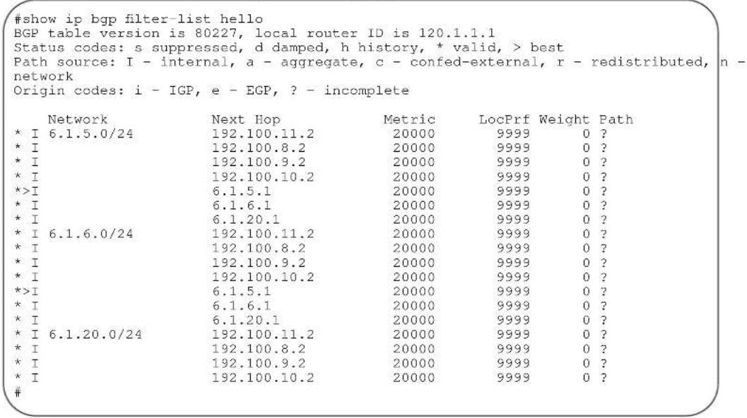
Table 12-6 defines the information displayed in Figure 12-13.
Table 12-6. Command Example fields: show ip bgp filter-list
| Field Description | |
| Path source codes Lists the path sources shown to the right of the last AS number in the Path column:i = internal route entrya = aggregate route entryc = external confederation route entryn = network route entryr = redistributed route entry | |
| Next Hop Displays the next hop address of the BGP router.If 0.0.0.0 is listed in this column, then local routes exist in the routing table. | |
| Metric Displays the BGP route's metric, if assigned. | |
| LocPrf Displays the BGP LOCAL_PREF attribute for the route. | |
| Weight Displays the route's weight | |
| Path Lists all the ASs the route passed through to reach the destination network. | |
Command History
Version 7.8.1.0 Introduced support on S-Series
Version 7.7.1.0 Introduced support on C-Series
show ip bgp flap-statistics

View flap statistics on BGP routes.
Syntax
show ip bgp [ipv4 unicast] flap-statistics [ip-address [mask]] [filter-list as-path-name] [regexp regular-expression]
Parameters
| ipv4 unicast | (OPTIONAL) Enter the ipv4 unicast keywords to view information only related to ipv4 unicast routes. |
| ip-address | (OPTIONAL) Enter the IP address (in dotted decimal format) of the BGP network to view information only on that network. |
| mask | (OPTIONAL) Enter the network mask (in slash prefix (/x) format) of the BGP network address. |
| filter-list as-path-name | (OPTIONAL) Enter the keyword filter-list followed by the name of a configured AS-PATH ACL. |
| regexp regular-expression | Enter a regular expression then use one or a combination of the following characters to match:.= (period) any single character (including a white space)* = (asterisk) the sequences in a pattern (0 or more sequences)+ = (plus) the sequences in a pattern (1 or more sequences)? = (question mark) sequences in a pattern (either 0 or 1 sequences). You must enter an escape sequence (CTRL+v) prior to entering the ? regular expression.[ ] = (brackets) a range of single-character patterns.( ) = (parenthesis) groups a series of pattern elements to a single element { } = (braces) minimum and the maximum match count^ = (caret) the beginning of the input string. If the caret is used at the beginning of a sequence or range, it matches on everything BUT the characters specified.$ = (dollar sign) the end of the output string. |
Command Modes
EXEC
EXEC Privilege
Example
Figure 12-14. Command Example: show ip bgp flap-statistics
>show ip bgp flap
BGP table version is 210851, local router ID is 63.114.8.2
Status codes: s suppressed, d damped, h history, * valid, > best
Path source: I - internal, a - aggregate, c - confed-external, r - redistributed, n - network
Origin codes: i - IGP, e - EGP, ? - incomplete
Network From Flaps Duration Reuse Path
Table 12-7 defines the information displayed in Figure 12-14.
Table 12-7. show ip bgp flap-statistics Command Example Fields
| Field Description | |
| Network Displays the network ID to which the route is flapping. | |
| From Displays the IP address of the neighbor advertising the flapping route. | |
| Flaps Displays the number of times the route flapped. | |
| Duration Displays the hours:minutes:seconds since the route first flapped. | |
| Reuse Displays the hours:minutes:seconds until the flapped route is available. | |
| Path Lists all the ASs the flapping route passed through to reach the destination network. | |
Command History
Version 7.8.1.0 Introduced support on S-Series
Version 7.7.1.0 Introduced support on C-Series
show ip bgp inconsistent-as

View routes with inconsistent originating Autonomous System (AS) numbers, that is, prefixes that are announced from the same neighbor AS but with a different AS-Path.
Syntax
show ip bgp [ipv4 unicast] inconsistent-as
Command Modes
EXEC
EXEC Privilege
Example
Figure 12-15. Command Example: show ip bgp inconsistent-as (Partial)
| >show ip bgp inconsistent-as | ||||
| BGP table version is 280852, local router ID is 10.1.2.100 | ||||
| Status codes: s suppressed, d damped, h history, * valid, > best | ||||
| Path source: I - internal, c - confed-external, r - redistributed, n - network | ||||
| Origin codes: i - IGP, e - EGP, ? - incomplete | ||||
| Network | Next Hop | Metric | LocPrf Weight Path | |
| * | 3.0.0.0/8 | 63.114.8.33 | 0 18508 209 7018 80 | |
| * | 63.114.8.34 | 0 18508 209 7018 80 i | ||
| * | 63.114.8.60 | 0 18508 209 7018 80 i | ||
| *> | 63.114.8.33 | 0 18508 701 80 i | ||
| *> | 3.18.135.0/24 | 63.114.8.60 | 0 18508 209 7018 ? | |
| * | 63.114.8.34 | 0 18508 209 7018 ? | ||
| * | 63.114.8.33 | 0 18508 701 7018 ? | ||
| * | 63.114.8.33 | 0 18508 209 7018 ? | ||
| *> | 4.0.0.0/8 | 63.114.8.60 | 0 18508 209 1 i | |
| * | 63.114.8.34 | 0 18508 209 1 i | ||
| * | 63.114.8.33 | 0 18508 701 1 i | ||
| * | 63.114.8.33 | 0 18508 209 1 i | ||
| * | 6.0.0.0/20 | 63.114.8.60 | 0 18508 209 3549 i | |
| * | 63.114.8.34 | 0 18508 209 3549 i | ||
| *> | 63.114.8.33 | 0 | 0 18508 ? | |
| * | 63.114.8.33 | 0 18508 209 3549 i | ||
| * | 9.2.0.0/16 | 63.114.8.60 | 0 18508 209 701 i | |
| * | 63.114.8.34 | 0 18508 209 701 i | ||
| --More-- | ||||
Table 12-8. show ip bgp inconsistent-as Command Example Fields
| Fields Description | |
| Network Displays the destination network prefix of each BGP route. | |
| Next Hop Displays the next hop address of the BGP router.If 0.0.0.0 is listed in this column, then local routes exist in the routing table. | |
| Metric Displays the BGP route's metric, if assigned. | |
| LocPrf Displays the BGP LOCAL_PREF attribute for the route. | |
| Weight Displays the route's weight | |
| Path Lists all the ASs the route passed through to reach the destination network. | |
Command History
Version 7.8.1.0 Introduced support on S-Series
Version 7.7.1.0 Introduced support on C-Series
show ip bgp neighbors

Displays routing information exchanged by BGP neighbors.
Syntax
show ip bgp [ipv4 unicast] neighbors [ipv4-neighbor-addr | ipv6-neighbor-addr] [advertised-routes | dampened-routes | detail | flap-statistics | routes | {received-routes [network [network-mask]] | {denied-routes [network [network-mask]]}]
Parameters
| ipv4 unicast | (OPTIONAL) Enter the ipv4 unicast keywords to view information only related to IPv4 unicast routes. |
| ipv4-neighbor-addr | ipv6-neighbor-addr | (OPTIONAL) Enter the IP address of the neighbor to view only BGP route information exchanged with that neighbor. |
| advertised-routes | (OPTIONAL) Enter the keywords advertised-routes to view only the routes the neighbor sent. |
| dampened-routes | (OPTIONAL) Enter the keyword dampened-routes to view information on dampened routes from the BGP neighbor. |
| detail | (OPTIONAL) Enter the keyword detail to view neighbor-specific internal information for the IPv4 Unicast address family. |
| flap-statistics | (OPTIONAL) Enter the keyword flap-statistics to view flap statistics on the neighbor's routes. |
| routes | (OPTIONAL) Enter the keywords routes to view only the neighbor's feasible routes. |
| received-routes [network [network-mask] | (OPTIONAL) Enter the keywords received-routes followed by either the network address (in dotted decimal format) or the network mask (in slash prefix format) to view all information received from neighbors.Note: neighbor soft-reconfiguration inbound must be configured prior to viewing all the information received from the neighbors. |
| denied-routes [network [network-mask] | (OPTIONAL) Enter the keywords denied-routes followed by either the network address (in dotted decimal format) or the network mask (in slash prefix format) to view all information on routes denied via neighbor inbound filters. |
Command Modes
EXEC
EXEC Privilege
Command History
| Version 7.8.1.0 Introduced support on S-Series | |
| Version 7.7.1.0 Introduced support on C-Series | |
| Version 7.5.1.0 | Added detail option and output now displays default MED value |
| Version 7.2.1.0 Added received and denied route options | |
| Version 6.3.10 The output is changed to display the total number of advertised prefixes | |
Example 1
Figure 12-16. Command Example: show ip bgp neighbors (Partial)
#show ip bgp neighbors

BGP neighbor is 100.10.10.2, remote AS 200, external link
    BGP version 4, remote router ID 192.168.2.101
    BGP state ESTABLISHED, in this state for 00:16:12
    Last read 00:00:12, last write 00:00:03
    Hold time is 180, keepalive interval is 60 seconds
Received 1404 messages, 0 in queue
    3 opens, 1 notifications, 1394 updates
    6 keepalives, 0 route refresh requests
Sent 48 messages, 0 in queue
    3 opens, 2 notifications, 0 updates
    43 keepalives, 0 route refresh requests
Minimum time between advertisement runs is 30 seconds
Minimum time before advertisements start is 0 seconds

Capabilities received from neighbor for IPv4 Unicast :
    MULTIPROTO_EXT(1)
    ROUTE_REFRESH(2)
    CISCO_ROUTE_REFRESH(128)

Capabilities advertised to neighbor for IPv4 Unicast :
    MULTIPROTO_EXT(1)
    ROUTE_REFRESH(2)
    ROUTE_REFRESH(2)
    GRACEFUL_RESTART(64)
    CISCO_ROUTE_REFRESH(128)

Route map for incoming advertisements is test
Maximum prefix set to 4 with threshold 75

For address family: IPv4 Unicast
BGP table version 34, neighbor version 34
5 accepted prefixes consume 20 bytes
Prefix advertised 0, denied 4, withdrawn 0

Prefixes accepted 1 (consume 4 bytes), withdrawn 0 by peer
Prefixes advertised 0, rejected 0, withdrawn 0 from peer

Connections established 2; dropped 1
Last reset 00:18:21, due to Maximum prefix limit reached
Example 2
Figure 12-17. Command Example: show ip bgp neighbors advertised-routes
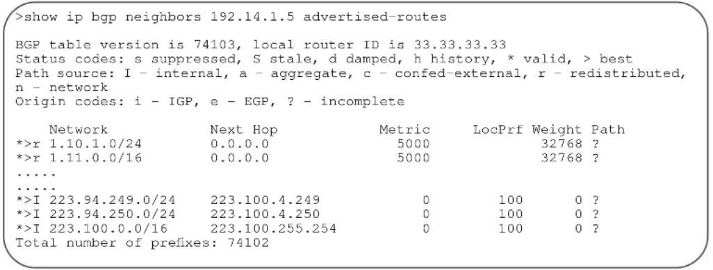
Example 3
Figure 12-18. Command Example: show ip bgp neighbors received-routes
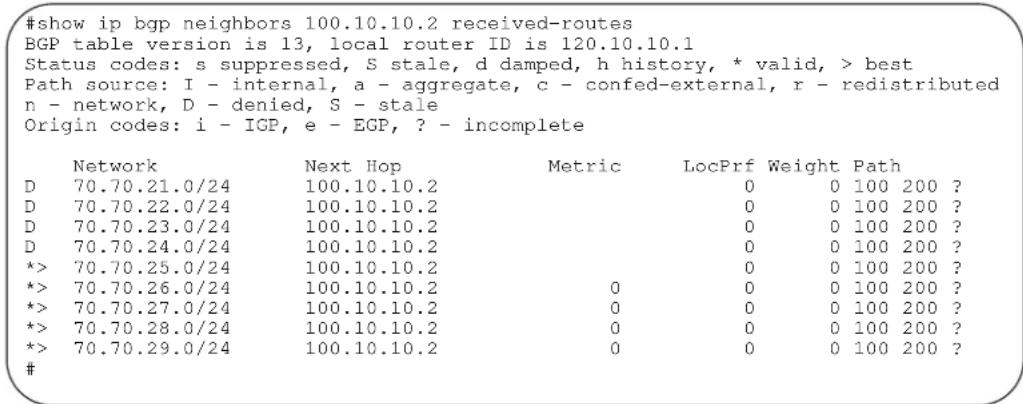
Example 4
Figure 12-19. Command Example: show ip bgp neighbors denied-routes
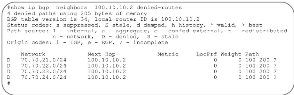
Table 12-9. Command Example fields: show ip bgp neighbors
| Lines beginning with Description | |
| BGP neighbor Displays the BGP neighbor address and its AS number. The last phrase in the line indicates whether the link between the BGP router and its neighbor is an external or internal one. If they are located in the same AS, then the link is internal; otherwise the link is external. | |
| BGP version Displays the BGP version (always version 4) and the remote router ID. | |
Table 12-9. Command Example fields: show ip bgp neighbors
| Lines beginning with | Description |
| BGP state Displays the neighbor's BGP state and the amount of time in hours:minutes:seconds it has been in that state. | |
| Last read This line displays the following information:last read is the time (hours:minutes:seconds) the router read a message from its neighborhold time is the number of seconds configured between messages from its neighborkeepalive interval is the number of seconds between keepalive messages to help ensure that the TCP session is still alive. | |
| Received messages This line displays the number of BGP messages received, the number of notifications (error messages) and the number of messages waiting in a queue for processing. | |
| Sent messages The line displays the number of BGP messages sent, the number of notifications (error messages) and the number of messages waiting in a queue for processing. | |
| Received updates This line displays the number of BGP updates received and sent. | |
| Soft reconfiguration This line indicates that soft reconfiguration inbound is configured. | |
| Minimum time Displays the minimum time, in seconds, between advertisements. | |
| (list of inbound and outbound policies) | Displays the policy commands configured and the names of the Route map, AS-PATH ACL or Prefix list configured for the policy. |
| For address family: Displays IPv4 Unicast as the address family. | |
| BGP table version Displays the which version of the primary BGP routing table the router and the neighbor are using. | |
| accepted prefixes Displays the number of network prefixes accepted by the router and the amount of memory used to process those prefixes. | |
| Prefix advertised Displays the number of network prefixes advertised, the number rejected and the number withdrawn from the BGP routing table. | |
| Connections established Displays the number of TCP connections established and dropped between the two peers to exchange BGP information. | |
| Last reset | Displays the amount of time since the peering session was last reset. Also states if the peer resets the peering session.If the peering session was never reset, the word never is displayed. |
| Local host: | Displays the peering address of the local router and the TCP port number. |
| Foreign host: | Displays the peering address of the neighbor and the TCP port number. |
Related Commands
show ip bgp
View the current BGP routing table.
show ip bgp next-hop

View all next hops (via learned routes only) with current reachability and flap status. This command only displays one path, even if the next hop is reachable by multiple paths.
Syntax show ip bgp next-hop
Command Modes
EXEC
EXEC Privilege
Example
Figure 12-20. Command Example: show ip bgp next-hop
| >show ip bgp next-hop | ||||||
| Next-hop | Via | RefCount | Cost | Flaps | Time Elapsed | |
| 63.114.8.33 | 63.114.8.33, Gi 12/22 | 240984 | 0 | 0 | 00:18:25 | |
| 63.114.8.34 | 63.114.8.34, Gi 12/22 | 135152 | 0 | 0 | 00:18:13 | |
| 63.114.8.35 | 63.114.8.35, Gi 12/22 | 1 | 0 | 0 | 00:18:07 | |
| 63.114.8.60 | 63.114.8.60, Gi 12/22 | 135155 | 0 | 0 | 00:18:11 | |
Table 12-10. Command Example fields: show ip bgp next-hop
| Field Description | |
| Next-hop Displays the next-hop IP address. | |
| Via Displays the IP address and interface used to reach the next hop. | |
| RefCount Displays the number of BGP routes using this next hop. | |
| Cost Displays the cost associated with using this next hop. | |
| Flaps Displays the number of times the next hop has flapped. | |
| Time Elapsed Displays the time elapsed since the next hop was learned. If the route is down, then this field displays time elapsed since the route went down. | |
Command History
Version 7.8.1.0 Introduced support on S-Series
Version 7.7.1.0 Introduced support on C-Series
show ip bgp paths

View all the BGP path attributes in the BGP database.
Syntax
show ip bgp paths [regexp regular-expression]
Parameters
regexp regular-expression
Enter a regular expression then use one or a combination of the following characters to match:
= (period) any single character (including a white space)
^* = (asterisk) the sequences in a pattern (0 or more sequences)
+ = (plus) the sequences in a pattern (1 or more sequences)
? = (question mark) sequences in a pattern (either 0 or 1 sequences). You must enter an escape sequence (CTRL+v) prior to entering the ? regular expression.
[ ] = (brackets) a range of single-character patterns.
() = (parenthesis) groups a series of pattern elements to a single element
= (braces) minimum and the maximum match count
^ = (caret) the beginning of the input string. If the caret is used at the beginning of a sequence or range, it matches on everything BUT the characters specified.
\$ = (dollar sign) the end of the output string.
Command Modes
EXEC
EXEC Privilege
Example
Figure 12-21. Command Example: show ip bgp paths (Partial)
| #show ip bgp path Total 16 Paths | ||||
| Address | Hash | Refcount | Metric | Path |
| 0x1efe7e5c | 15 | 10000 | 32 ? | |
| 0x1efe7e1c | 71 | 10000 | 23 ? | |
| 0x1efe7ddc | 127 | 10000 | 22 ? | |
| 0x1efe7d9c | 183 | 10000 | 43 ? | |
| 0x1efe7d5c | 239 | 10000 | 42 ? | |
| 0x1efe7c9c | 283 | 6 | {102 103} ? | |
| 0x1efe7b1c | 287 | 336 | 20000 | ? |
| 0x1efe7dlc | 295 | 10000 | 13 ? | |
| 0x1efe7c5c | 339 | 6 | {92 93} ? | |
| 0x1efe7cdc | 351 | 10000 | 12 ? | |
| 0x1efe7c1c | 395 | 6 | {82 83} ? | |
| 0x1efe7bdc | 451 | 6 | {72 73} ? | |
| 0x1efe7b5c | 491 | 78 | 0 | ? |
| 0x1efe7adc | 883 | 2 | 120 | i |
| 0x1efe7e9c | 983 | 10000 | 33 ? | |
| 0x1efe7b9c | 1003 | 6 | 0 | i |
Table 12-11. Command Example fields: show ip bgp paths
| Field Description | |
| Total Displays the total number of BGP path attributes. | |
| Address Displays the internal address | where the path attribute is stored. |
| Hash Displays the hash bucket where | the path attribute is stored. |
| Refcount Displays the number of BGP routes using this path attribute. | |
| Metric Displays the MED attribute for this path attribute. | |
| Path Displays the AS path for the route, with the origin code for the route listed last.Numbers listed between braces {} are AS_SET information. | |
Command History
Version 7.8.1.0 Introduced support on S-Series
Version 7.7.1.0 Introduced support on C-Series
show ip bgp paths as-path

View all unique AS-PATHs in the BGP database
Syntax
show ip bgp paths as-path
Command Modes
EXEC
EXEC Privilege
Example
Figure 12-22. Command Example: show ip bgp paths as-path (Partial)
#show ip bgp paths as-path
Total 13 AS-Paths
Address Hash Refcount AS-Path
0x1ea3clec 251 1 42
0x1ea3c25c 251 1 22
0x1ea3c1b4 507 1 13
0x1ea3c304 507 1 33
0x1ea3c10c 763 1 {92 93}
0x1ea3c144 763 1 {102 103}
0x1ea3c17c 763 1 12
0x1ea3c2cc 763 1 32
0x1ea3c09c 764 1 {72 73}
0x1ea3c0d4 764 1 {82 83}
0x1ea3c224 1019 1 43
0x1ea3c294 1019 1 23
0x1ea3c02c 1021 4
#
Table 12-12. Command Example fields: show ip bgp paths community
| Field Description | |
| Address Displays the internal address where the path attribute is stored. | |
| Hash Displays the hash bucket where the path attribute is stored. | |
| Refcount Displays the number of BGP routes using these AS-Paths. | |
| AS-Path Displays the AS paths for this route, with the origin code for the route listed last.Numbers listed between braces {} are AS_SET information. | |
Command History
Version 7.8.1.0 Introduced support on S-Series
Version 7.7.1.0 Introduced support on C-Series
show ip bgp paths community

View all unique COMMUNITY numbers in the BGP database.
Syntax
show ip bgp paths community
Command Modes
EXEC
EXEC Privilege
Example
Figure 12-23. Command Example: show ip bgp paths community (Partial)
| E1200-BGP>show ip bgp paths community | ||||||
| Total 293 Communities | ||||||
| Address | Hash | Refcount | Community | |||
| 0x1ec88a5c | 3 | 4 | 209:209 | 209:6059 | 209:31272 | 3908:900 19092:300 |
| 0x1e0f10ec | 15 | 4 | 209:209 | 209:3039 | 209:31272 | 3908:900 19092:300 |
| 0x1c902234 | 37 | 2 | 209:209 | 209:7193 | 209:21362 | 3908:900 19092:300 |
| 0x1f588cd4 | 41 | 24 | 209:209 | 209:6253 | 209:21362 | 3908:900 19092:300 |
| 0x1e805884 | 46 | 2 | 209:209 | 209:21226 | 286:777 286:3033 | 1899:3033 |
| 64675:21092 | ||||||
| 0x1e433f4c | 46 | 8 | 209:209 | 209:5097 | 209:21362 | 3908:900 19092:300 |
| 0x1f173294 | 48 | 16 | 209:209 | 209:21226 | 286:40 286:777 286:3040 5606:40 | |
| 12955:5606 | ||||||
| 0x1c9f8e24 | 50 | 6 | 209:209 | 209:4069 | 209:21362 | 3908:900 19092:300 |
| 0x1c9f88e4 | 53 | 4 | 209:209 | 209:3193 | 209:21362 | 3908:900 19092:300 |
| 0x1f58a944 | 57 | 6 | 209:209 | 209:2073 | 209:21362 | 3908:900 19092:300 |
| 0x1ce6be44 | 80 | 2 | 209:209 | 209:999 209:40832 | ||
| 0x1c6e2374 | 80 | 2 | 209:777 | 209:41528 | ||
| 0x1f58ad6c | 82 | 46 | 209:209 | 209:41528 | ||
| 0x1c6e2064 | 83 | 2 | 209:777 | 209:40832 | ||
| 0x1f588ecc | 85 | 570 | 209:209 | 209:40832 | ||
| 0x1f57ccoc | 98 | 2 | 209:209 | 209:21226 286:3031 13646:1044 13646:1124 | ||
| 13646:1154 13646:1164 13646:1184 13646:1194 13646:1204 13646:1214 13646:1224 | ||||||
| 13646:1234 13646:1244 13646:1254 13646:1264 13646:3000 | ||||||
| Oxld65b2ac 117 6 209:209 209:999 209:31272 | ||||||
| Ox1f5854ac 119 18 209:209 209:21226 286:108 286:111 286:777 286:3033 | ||||||
Table 12-13. Command Example fields: show ip bgp paths community
| Field Description | |
| Address Displays the internal address where the path attribute is stored. | |
| Hash Displays the hash bucket where the path attribute is stored. | |
| Recount Displays the number of BGP routes using these communities. | |
| Community Displays the community attributes in this BGP path. | |
Command History
Version 7.8.1.0 Introduced support on S-Series
Version 7.7.1.0 Introduced support on C-Series
show ip bgp peer-group

Enables you to view information on the BGP peers in a peer group.
Syntax
show ip bgp [ipv4 unicast] peer-group [peer-group-name [detail | summary]]
Parameters
| ipv4 unicast | (OPTIONAL) Enter the ipv4 unicast keywords to view information only related to ipv4 unicast routes. |
| peer-group-name | (OPTIONAL) Enter the name of a peer group to view information about that peer group only. |
| detail | (OPTIONAL) Enter the keyword detail to view detailed status information of the peers in that peer group. |
| summary | (OPTIONAL) Enter the keyword summary to view status information of the peers in that peer group.The output is the same as that found in show ip bgp summary command |
Command Modes
EXEC
EXEC Privilege
Example
Figure 12-24. Command Example: show ip bgp peer-group (Partial)
#show ip bgp peer-group
Peer-group RT-PEERS
Description: ***peering-with-RT***
BGP version 4
Minimum time between advertisement runs is 30 seconds
For address family: IPv4 Unicast
BGP neighbor is RT-PEERS
Number of peers in this group 20
Peer-group members (* - outbound optimized):
12.1.1.2*
12.1.1.3*
12.1.1.4*
12.1.1.5*
12.1.1.6*
12.2.1.2*
12.2.1.3*
12.2.1.4*
12.2.1.5*
12.2.1.6*
12.3.1.2*
12.3.1.3*
12.3.1.4*
12.3.1.5*
12.3.1.6*
12.4.1.2*
12.4.1.3*
12.4.1.4*
12.4.1.5*
12.4.1.6*
Table 12-14. Command Example fields: show ip bgp peer-group
| Line beginning with Description | |
| Peer-group Displays the peer | group's name. |
| Administratively shut Displays | the peer group's status if the peer group is not enabled.If the peer group is enabled, this line is not displayed. |
| BGP version Displays the BGP | version supported. |
| Minimum time Displays the | time interval between BGP advertisements. |
| For address family Displays | Pv4 Unicast as the address family. |
| BGP neighbor Displays the name of the BGP neighbor. | |
| Number of peers Displays the number of peers currently configured for this peer group. | |
| Peer-group members: Lists the | IP addresses of the peers in the peer group.If the address is outbound optimized, a * is displayed next to the IP address. |
| Related Commands | neighbor peer-group (assigning peers) Assign peer to a peer-group. |
| neighbor peer-group (creating group) Create a peer group. | |
| show ip bgp peer-group (multicast) View information on the BGP peers in a peer group. | |
| Command History | |
| Version 7.8.1.0 Introduced support on S-Series | |
| Version 7.7.1.0 Introduced support on C-Series | |
| Version 7.8.1.0 Introduced support on S-Series |
show ip bgp regexp

Display the subset of BGP routing table matching the regular expressions specified.
Syntax
show ip bgp regexp regular-expression [character]
| Parameters | regular-expression [character] | Enter a regular expression then use one or a combination of the following characters to match:.= (period) any single character (including a white space)* = (asterisk) the sequences in a pattern (0 or more sequences)+ = (plus) the sequences in a pattern (1 or more sequences)? = (question mark) sequences in a pattern (either 0 or 1 sequences). You must enter an escape sequence (CTRL+v) prior to entering the ? regular expression.[ ] = (brackets) a range of single-character patterns.( ) = (parenthesis) groups a series of pattern elements to a single element{} = (braces) minimum and the maximum match count^ = (caret) the beginning of the input string. If the caret is used at the beginning of a sequence or range, it matches on everything BUT the characters specified.$ = (dollar sign) the end of the output string. |
Command Modes
EXEC
EXEC Privilege
Example Figure 12-25. Command Example: show ip bgp regexp (Partial)
| #show ip bgp regexp ^2914+ | |||||
| BGP table version is 3700481, local router ID is 63.114.8.35 | |||||
| Status codes: s suppressed, S stale, d damped, h history, * valid, > best | |||||
| Path source: I - internal, a - aggregate, c - confed-external, r - redistributed, n - network | |||||
| Origin codes: i - IGP, e - EGP, ? - incomplete | |||||
| Network | Next Hop | Metric | LocPrf | Weight Path | |
| *>I 3.0.0.0/8 | 1.1.1.2 | 0 | 100 | 0 2914 1239 80 i | |
| *>I 4.0.0.0/8 | 1.1.1.2 | 0 | 100 | 0 2914 3356 i | |
| *>I 4.17.225.0/24 | 1.1.1.2 | 0 | 100 | 0 2914 11853 11853 11853 11853 11853 11853 6496 | |
| *>I 4.17.226.0/23 | 1.1.1.2 | 0 | 100 | 0 2914 11853 11853 11853 11853 11853 6496 | |
| *>I 4.17.251.0/24 | 1.1.1.2 | 0 | 100 | 0 2914 11853 11853 11853 11853 11853 6496 | |
| *>I 4.17.252.0/23 | 1.1.1.2 | 0 | 100 | 0 2914 11853 11853 11853 11853 6496 | |
| *>I 4.19.2.0/23 | 1.1.1.2 | 0 | 100 | 0 2914 701 6167 6167 6167 i | |
| *>I 4.19.16.0/23 | 1.1.1.2 | 0 | 100 | 0 2914 701 6167 6167 6167 i | |
| *>I 4.21.80.0/22 | 1.1.1.2 | 0 | 100 | 0 2914 174 4200 16559 i | |
| *>I 4.21.82.0/24 | 1.1.1.2 | 0 | 100 | 0 2914 174 4200 16559 i | |
| *>I 4.21.252.0/23 | 1.1.1.2 | 0 | 100 | 0 2914 701 6389 8063 19198 i | |
| *>I 4.23.180.0/24 | 1.1.1.2 | 0 | 100 | 0 2914 3561 6128 30576 i | |
| *>I 4.36.200.0/21 | 1.1.1.2 | 0 | 100 | 0 2914 14742 11854 14135 i | |
| *>I 4.67.64.0/22 | 1.1.1.2 | 0 | 100 | 0 2914 11608 19281 i | |
| *>I 4.78.32.0/21 | 1.1.1.2 | 0 | 100 | 0 2914 3491 29748 i | |
| *>I 6.1.0.0/16 | 1.1.1.2 | 0 | 100 | 0 2914 701 668 i | |
| *>I 6.2.0.0/22 | 1.1.1.2 | 0 | 100 | 0 2914 701 668 i | |
| *>I 6.3.0.0/18 | 1.1.1.2 | 0 | 100 | 0 2914 701 668 i | |
Table 12-15. Command Example fields: show ip bgp regexp
| Field Description |
| Network Displays the destination network prefix of each BGP route. |
| Next Hop Displays the next hop address of the BGP router.If 0.0.0.0 is listed in this column, then non-BGP routes exist in the router’s routing table. |
| Metric Displays the BGP router’s metric, if assigned. |
| LocPrf Displays the BGP LOCAL_PREF attribute for the route. |
| Weight Displays the route’s weight |
| Path Lists all the AS paths the route passed through to reach the destination network. |
Command History
| Version 7.8.1.0 | Introduced support on S-Series |
| Version 7.7.1.0 | Introduced support on C-Series |
show ip bgp summary

Enables you to view the status of all BGP connections.
Syntax show ip bgp [ipv4 unicast] summary
Command Modes
EXEC
EXEC Privilege
Example
Figure 12-26. Command Example: show ip bgp summary
| #show ip bgp summary | ||||||||
| BGP router identifier 120.10.10.1, local AS number 100 | ||||||||
| BGP table version is 34, main routing table version 34 | ||||||||
| 9 network entrie(s) using 1372 bytes of memory | ||||||||
| 5 paths using 380 bytes of memory | ||||||||
| 4 denied paths using 164 bytes of memory | ||||||||
| BGP-RIB over all using 385 bytes of memory | ||||||||
| 2 BGP path attribute entrie(s) using 168 bytes of memory | ||||||||
| 1 BGP AS-PATH entrie(s) using 39 bytes of memory | ||||||||
| 1 BGP community entrie(s) using 43 bytes of memory | ||||||||
| 2 neighbor(s) using 7232 bytes of memory | ||||||||
| Neighbor | AS | MsgRcvd | MsgSent | TblVer | InQ | OutQ | Up/Down | State/Pfx |
| 100.10.10.2 | 200 | 46 | 41 | 34 | 0 | 0 | 00:14:33 | 5 |
| 120.10.10.2 | 300 | 40 | 47 | 34 | 0 | 0 | 00:37:10 | 0 |
Table 12-16. Command Example fields: show ip bgp summary
| Field Description | |
| BGP router identifier Displays the local router ID and the AS number. | |
| BGP table version Displays the BGP | table version and the main routing table version. |
| network entries Displays the number of network entries and route paths and the amount of memory used to process those entries. | |
| paths Displays the number of paths and the amount of memory used. | |
| denied paths Displays the number of denied paths and the amount of memory used. | |
| BGP path attribute entries Displays the number of BGP path attributes and the amount of memory used to process them. | |
| BGP AS-PATH entries Displays the number of BGP AS_PATH attributes processed and the amount of memory used to process them. | |
| BGP community entries Displays the number of BGP COMMUNITY attributes processed and the amount of memory used to process them. The show ip bgp community command provides more details on the COMMUNITY attributes. | |
| Dampening enabled Displayed only when dampening is enabled. Displays the number of paths designated as history, dampened, or penalized. | |
| Neighbor Displays the BGP neighbor address. | |
| AS Displays the AS number of the neighbor. | |
| MsgRcvd | Displays the number of BGP messages that neighbor received. |
| MsgSent | Displays the number of BGP messages that neighbor sent. |
| TblVer | Displays the version of the BGP table that was sent to that neighbor. |
| InQ | Displays the number of messages from that neighbor waiting to be processed. |
| OutQ | Displays the number of messages waiting to be sent to that neighbor. If a number appears in parentheses, the number represents the number of messages waiting to be sent to the peer group. |
Table 12-16. Command Example fields: show ip bgp summary
| Field Description | |
| Up/Down Displays the amount of time that the neighbor is in the Established stage.If the neighbor has never moved into the Established stage, the word never is displayed.The output format is:Time Established----Display Example< 1 day ---- 00:12:23 (hours:minutes:seconds)< 1 week ---- 1d21h (DaysHours)> 1 week ---- 11w2d (WeeksDays) | |
| State/Pfxrcd If the neighbor is in Established stage, the number of network prefixes received.If a maximum limit was configured with theneighbor maximum-prefix command, (prfxd) appears in this column.If the neighbor is not in Established stage, the current stage is displayed (Idle, Connect, Active, OpenSent, OpenConfirm) When the peer is transitioning between states and clearing the routes received, the phrase (Purging) may appear in this column.If the neighbor is disabled, the phrase (Admin shut) appears in this column. | |
Command History
Version 7.8.1.0 Introduced support on S-Series
Version 7.7.1.0 Introduced support on C-Series
show running-config bgp

Use this feature to display the current BGP configuration.
Syntax
show running-config bgp
Defaults
No default values or behavior
Command Modes
EXEC Privilege
Command History
Version 7.8.1.0 Introduced on S-Series
Version 7.7.1.0 Introduced on C-Series
Version 7.6.1.0 Introduced on E-Series
timers bgp

Adjust BGP Keep Alive and Hold Time timers.
Syntax
timers bgp keepalive holdtime
To return to the default, enter no timers bgp.
Parameters
| keepalive | Enter a number for the time interval, in seconds, between keepalive messages sent to the neighbor routers. Range: 1 to 65535 Default: 60 seconds |
| holdtime | Enter a number for the time interval, in seconds, between the last keepalive message and declaring the router dead. Range: 3 to 65535 Default: 180 seconds |
Defaults
No default values or behavior
Command Modes
ROUTER BGP
Command History
Version 7.8.1.0 Introduced on S-Series
Version 7.7.1.0 Introduced on C-Series
Version 7.6.1.0 Introduced on E-Series
MBGP Commands
Multiprotocol BGP (MBGP) is an enhanced BGP that enables multicast routing policy throughout the Internet and connecting multicast topologies between BGP and autonomous systems (AS). FTOS MBGP is implemented as per IETF RFC 2828.
FTOS version 7.8.1.0 and later support MBGP for IPv6 on E_T and C platforms.
FTOS version 7.8.1.0 and later supports MBGP for IPv4 Multicast only on the S platform.
FTOS version 8.2.1.0 and later support MBGP on the E-Series ExaScale E platform.
The MBGP commands are:
- address family ipv4 multicast (MBGP)
- aggregate-address
- bgp dampening
- bgp soft-reconfig-backup
- clear ip bgp dampening
- clear ip bgp flap-statistics
• clear ip bgp ipv4 multicast soft - debug ip bgp dampening
- debug ip bgp dampening
- debug ip bgp dampening
- debug ip bgp peer-group updates
- debug ip bgp ipv4 unicast soft-reconfiguration
- debug ip bgp updates
- distance bgp
-
neighbor activate
• neighbor advertisement-interval -
neighbor default-originate
- neighbor distribute-list
- neighbor filter-list
- neighbor maximum-prefix
- neighbor next-hop-self
- neighbor remove-private-as
- neighbor route-map
- neighbor route-reflector-client
- neighbor soft-reconfiguration inbound
- network
- redistribute
- redistribute ospf
• show ip bgp ipv4 multicast
• show ip bgp cluster-list
• show ip bgp community
• show ip bgp community-list
• show ip bgp dampened-paths
• show ip bgp filter-list
• show ip bgp flap-statistics
• show ip bgp inconsistent-as
• show ip bgp ipv4 multicast
• show ip bgp ipv4 multicast neighbors
• show ip bgp peer-group
• show ip bgp summary
address family ipv4 multicast (MBGP)

This command changes the context to SAFI (Subsequent Address Family Identifier).
Syntax address family ipv4 multicast
To remove SAFI context, use the no address family ipv4 multicast command.
Parameters
| ipv4 | Enter the keyword ipv4 to specify the address family as IPV4. |
| multicast | Enter the keyword multicast to specify multicast as SAFI. |
Defaults IPv4 Unicast
Command Modes ROUTER BGP (conf-router\_bgp)
Usage Information All subsequent commands will apply to this address family once this command is executed. You can exit from this AFI/SAFI to the IPv4 Unicast (the default) family by entering exit and returning to the Router BGP context.
Command History
| Version 7.8.1.0 Introduced support on S-Series for MBGP IPv4 Multicast |
| Version 7.7.1.0 Introduced support on C-Series |
aggregate-address

Summarize a range of prefixes to minimize the number of entries in the routing table.
Syntax
aggregate-address ip-address mask [advertise-map map-name] [as-set] [attribute-map map-name] [summary-only] [suppress-map map-name]
Parameters
| ip-address mask | Enter the IP address and mask of the route to be the aggregate address.Enter the IP address in dotted decimal format (A.B.C.D) and mask in /prefix format (/x). |
| advertise-mapmap-name | (OPTIONAL) Enter the keywordsadvertise-mapfollowed by thename of a configured route map to set filters for advertising an aggregateroute. |
| as-set | (OPTIONAL) Enter the keywordas-setto generate path attributeinformation and include it in the aggregate.AS_SET includes AS_PATHand community information from the routesincluded in the aggregated route. |
| attribute-map map-name | (OPTIONAL) Enter the keywordsattribute-mapfollowed by the nameof a configured route map to modify attributes of the aggregate, excludingAS_PATHand NEXT_HOP attributes. |
| summary-only | (OPTIONAL) Enter the keywordsummary-onlyto advertise only theaggregate address. Specific routes will not be advertised. |
| suppress-mapmap-name | (OPTIONAL) Enter the keywordssuppress-mapfollowed by thename of a configured route map to identify which more-specific routes inthe aggregate are suppressed. |
Defaults
Not configured.
Command Modes
ROUTER BGP Address Family (conf-router_bgp_af)
Usage Information
At least one of the routes included in the aggregate address must be in the BGP routing table for the configured aggregate to become active.
Do not add the as-set parameter to the aggregate. If routes within the aggregate are constantly changing, the aggregate will flap to keep track of the changes in the AS_PATH.
In route maps used in the suppress-map parameter, routes meeting the deny clause are not suppress; in other words, they are allowed. The opposite is true: routes meeting the permit clause are suppressed.
If the route is injected via the network command, that route will still appear in the routing table if the summary-only parameter is configured in the aggregate-address command.
The summary-only parameter suppresses all advertisements. If you want to suppress advertisements to only specific neighbors, use the neighbor distribute-list command.
Command History
Version 7.8.1.0 Introduced support on S-Series
Version 7.7.1.0 Introduced support on C-Series
bgp dampening
Enable MBGP route dampening.
Syntax bgp dampening [half-life time] [route-map map-name]
To disable route dampening, use the no bgp dampening [half-life time] [route-map map-name] command.
| Parameters | half-life time | (OPTIONAL) Enter the number of minutes after which the Penalty is decreased. After the router assigns a Penalty of 1024 to a route, the Penalty is decreased by half, after the half-life period expires.Range: 1 to 45.Default: 15 minutes |
| route-map map-name | (OPTIONAL) Enter the keyword route-map followed by the name of a configured route map.Only match commands in the configured route map are supported. |
Defaults Disabled.
Command Modes ROUTER BGP Address Family (conf-router_bgp_af)
| Command History | Version 7.8.1.0 Introduced support on S-Series |
| Version 7.7.1.0 Introduced support on C-Series | |
| Version 7.6.1.0 Introduced IPv6 MGBP support for E-Series |
bgp soft-reconfig-backup

Use this command only when route-refresh is not negotiated between peers to avoid having a peer resend BGP updates.
Syntax bgp soft-reconfig-backup
To return to the default setting, use the no bgp soft-reconfig-backup command.
Defaults Off
Command Modes ROUTER BGP ADDRESS FAMILY (conf-router_bgp_af)
Usage Information When soft-reconfiguration is enabled for a neighbor and the clear ip bgp soft in is executed, the update database stored in the router is replayed and updates are reevaluated. With this command, the replay and update process is triggered only if route-refresh request is not negotiated with the peer. If the request is indeed negotiated (upon execution of clear ip bgp soft in), then BGP sends a route-refresh request to the neighbor and receives all of the peer's updates.
| Related Commands | clear ip bgp ipv4 multicast soft in | Activate inbound policies without resetting the BGP TCP session. |
Command History
Version 8.4.1.0 Added support for IPv4 multicast and IPv6 unicast address families
Version 7.8.1.0 Introduced support on S-Series
Version 7.7.1.0 Introduced support on C-Series
Version 7.2.1.0 Introduced
clear ip bgp dampening

Clear information on route dampening.
Syntax
clear ip bgp dampening ipv4 multicast network network-mask
Parameters
| dampening | Enter the keyword dampening to clear route flap dampening information. |
| network | (OPTIONAL) Enter the network address in dotted decimal format (A.B.C.D). |
| network-mask | (OPTIONAL) Enter the network mask in slash prefix format (/x). |
Command Modes
EXEC Privilege
Command History
Version 7.8.1.0 Introduced support on S-Series
Version 7.7.1.0 Introduced support on C-Series
Version 7.6.1.0 Introduced IPv6 MGBP support for E-Series
clear ip bgp flap-statistics

Clear BGP flap statistics, which includes number of flaps and the time of the last flap.
Syntax
clear ip bgp ipv4 multicast flap-statistics network | filter-list list | regexp regexp
Parameters
Network
(OPTIONAL) Enter the network address to clear flap statistics in dotted decimal format (A.B.C.D).
| filter-list list | (OPTIONAL) Enter the keyword filter-list followed by the name of a configured AS-PATH list (max 16 characters). |
| regexp regexp | (OPTIONAL) Enter the keyword regexp followed by regular expressions. Use one or a combination of the following:.= (period) any single character (including a white space)* = (asterisk) the sequences in a pattern (0 or more sequences)+ = (plus) the sequences in a pattern (1 or more sequences)? = (question mark) sequences in a pattern (either 0 or 1 sequences). You must enter an escape sequence (CTRL+v) prior to entering the ? regular expression.[ ] = (brackets) a range of single-character patterns.( ) = (parenthesis) groups a series of pattern elements to a single element{ } = (braces) minimum and the maximum match count^ = (caret) the beginning of the input string. If the caret is used at the beginning of a sequence or range, it matches on everything BUT the characters specified.$ = (dollar sign) the end of the output string. |
Command Modes
EXEC Privilege
Command History
Version 7.8.1.0 Introduced support on S-Series
Version 7.7.1.0 Introduced support on C-Series
Version 7.6.1.0 Introduced IPv6 MGBP support for E-Series
clear ip bgp ipv4 multicast soft

Clear and reapply policies for IPv4 multicast routes without resetting the TCP connection; that is, perform BGP soft reconfiguration.
Syntax
clear ip bgp {* | as-number | ipv4-neighbor-addr | ipv6-neighbor-addr | peer-group name } ipv4 multicast soft [in | out]
Parameters
| * | Clear and reapply policies for all BGP sessions. |
| as-number Clear and reapply policies for all neighbors belonging to the AS. | |
| Range: 0-65535 (2-Byte) or1-4294967295 (4-Byte) or0.1-65535.65535 (Dotted format) | |
| ipv4-neighbor-addr | ipv6-neighbor-addr | Clear and reapply policies for a neighbor. |
| peer-group name | Clear and reapply policies for all BGP routers in the specified peer group. |
| ipv4 multicast | Clear and reapply policies for all IPv4 multicast routes. |
| in | Reapply only inbound policies. Note: If you enter soft, without an in or out option, both inbound and outbound policies are reset. |
| out | Reapply only outbound policies. Note: If you enter soft, without an in or out option, both inbound and outbound policies are reset. |
Command Modes
EXEC Privilege
Command History
Version 8.4.1.0 Added BGP Soft Reconfiguration support for IPv4 unicast and IPv6 routes
Version 7.8.1.0 Introduced support on S-Series
Version 7.7.1.0 Introduced support on C-Series
Version 7.2.1.0 Introduced
debug ip bgp dampening

View information on routes being dampened.
Syntax
debug ip bgp ipv4 multicast dampening
To disable debugging, enter no debug ip bgp ipv4 multicast dampening
Parameters
dampening
Enter the keyword dampening to clear route flap dampening information.
Command Modes
EXEC Privilege
Command History
Version 7.8.1.0 Introduced support on S-Series
Version 7.7.1.0 Introduced support on C-Series
Version 7.6.1.0 Introduced IPv6 MGBP support for E-Series
debug ip bgp ipv4 multicast soft-reconfiguration

Enable soft-reconfiguration debugging for IPv4 multicast routes.
Syntax
debug ip bgp [ipv4-address | ipv6-address | peer-group-name] ipv4 multicast soft-reconfiguration
To disable debugging, use the no debug ip bgp [ipv4-address | ipv6-address | peer-group-name] ipv4 multicast soft-reconfiguration command.
Parameters
ipv4-address ipv6-address
Enter the IP address of the neighbor on which you want to enable soft-reconfiguration debugging.
peer-group-name
Enter the name of the peer group on which you want to enable soft-reconfiguration debugging.
ipv4 multicast
Debug soft reconfiguration for IPv4 multicast routes.
Defaults
Disabled
Command Modes
EXEC Privilege
Usage Information
This command turns on BGP soft-reconfiguration inbound debugging for IPv4 multicast routes. If no neighbor is specified, debug is turned on for all neighbors.
Command History
Version 8.4.1.0 Introduced support for IPv4 multicast and IPv6 unicast routes
Version 7.8.1.0 Introduced support on S-Series
Version 7.7.1.0 Introduced support on C-Series
Version 7.2.1.0 Introduced
debug ip bgp peer-group updates
View information about BGP peer-group updates.
debug ip bgp peer-group peer-group-name updates [in | out]
To disable debugging, enter no debug ip bgp peer-group peer-group-name updates [in | out] command.
Parameters
| peer-group peer-group-name | Enter the keyword peer-group followed by the name of the peer-group. |
| updates | Enter the keyword updates to view BGP update information. |
| in | (OPTIONAL) Enter the keyword in to view only BGP updates received from neighbors. |
| out | (OPTIONAL) Enter the keyword out to view only BGP updates sent to neighbors. |
Command Modes
EXEC Privilege
Command History
Version 7.8.1.0 Introduced support on S-Series
Version 7.7.1.0 Introduced support on C-Series
Version 7.6.1.0 Introduced IPv6 MGBP support for E-Series
debug ip bgp updates

View information about BGP updates.
debug ip bgp updates [in | out]
To disable debugging, enter no debug ip bgp updates [in | out] command.
Parameters
| updates | Enter the keyword updates to view BGP update information. |
| in | (OPTIONAL) Enter the keyword in to view only BGP updates received from neighbors. |
| out | (OPTIONAL) Enter the keyword out to view only BGP updates sent to neighbors. |
Command Modes
EXEC Privilege
Defaults
Disabled.
Command History
Version 7.8.1.0 Introduced support on S-Series
Version 7.7.1.0 Introduced support on C-Series
Version 7.6.1.0 Introduced IPv6 MGBP support for E-Series
distance bgp

Define an administrative distance for routes.
Syntax
distance bgp external-distance internal-distance local-distance
To return to default values, enter no distance bgp.
Parameters
| external-distance | Enter a number to assign to routes learned from a neighbor external to the AS. Range: 1 to 255. Default: 20 |
| internal-distance | Enter a number to assign to routes learned from a router within the AS. Range: 1 to 255. Default: 200 |
| local-distance | Enter a number to assign to routes learned from networks listed in the network command. Range: 1 to 255. Default: 200 |
Defaults
external-distance = 20; internal-distance = 200; local-distance = 200.
Command Modes
ROUTER BGP (conf-router_bgp_af)

Caution: Dell Force10 recommends that you do not change the administrative distance of internal routes. Changing the administrative distances may cause routing table inconsistencies.
Usage Information
The higher the administrative distance assigned to a route means that your confidence in that route is low. Routes assigned an administrative distance of 255 are not installed in the routing table. Routes from confederations are treated as internal BGP routes.
Command History
Version 7.8.1.0 Introduced support on S-Series
Version 7.7.1.0 Introduced support on C-Series
Version 7.6.1.0 Introduced IPv6 MGBP support for E-Series
neighbor activate

This command allows the specified neighbor/peer group to be enabled for the current AFI/SAFI.
Syntax
neighbor [ip-address | peer-group-name] activate
To disable, use the no neighbor [ip-address | peer-group-name] activate command.
| Parameters | ip-address | (OPTIONAL) Enter the IP address of the neighbor in dotted decimal format. |
| peer-group-name | (OPTIONAL) Enter the name of the peer group | |
| activate | Enter the keywordactivateto enable the neighbor/peer group in the new AFI/SAFI. | |
| Defaults | Disabled | |
| mand Modes | ROUTER BGP Address Family (conf-router_bgp_af) | |
| Usage Information | By default, when a neighbor/peer group configuration is created in the Router BGP context, it is enabled for the IPv4/Unicast AFI/SAFI. By usingactivatein the new context, the neighbor/peer group is enabled for AFI/SAFI. | |
| Related Commands | address family ipv4 multicast (MBGP) Changes the context to SAFI | |
| Command History | Version 7.8.1.0 Introduced support on S-Series | |
| Version 7.7.1.0 Introduced support on C-Series | ||
| Version 7.6.1.0 Introduced IPv6 MGBP support for E-Series | ||
neighbor advertisement-interval

Set the advertisement interval between BGP neighbors or within a BGP peer group.
Syntax
neighbor {ip-address | peer-group-name} advertisement-interval seconds
To return to the default value, use the no neighbor {ip-address | peer-group-name} advertisement-interval command.
Parameters
| ip-address | Enter the IP address of the neighbor in dotted decimal format. |
| peer-group-name | Enter the name of the peer group to set the advertisement interval for all routers in the peer group. |
| seconds | Enter a number as the time interval, in seconds, between BGP advertisements.Range: 0 to 600 seconds.Default: 5 seconds for internal BGP peers; 30 seconds for external BGP peers. |
Defaults
seconds = 5 seconds (internal peers); seconds = 30 seconds (external peers)
Command Modes
ROUTER BGP Address Family (conf-router_bgp_af)
Command History
| Version 7.8.1.0 Introduced support on S-Series |
| Version 7.7.1.0 Introduced support on C-Series |
| Version 7.6.1.0 Introduced IPv6 MGBP support for E-Series |
neighbor default-originate

Inject the default route to a BGP peer or neighbor.
Syntax
neighbor {ip-address | peer-group-name} default-originate [route-map map-name]
To remove a default route, use the no neighbor {ip-address | peer-group-name} default-originate command.
Parameters
| ip-address | Enter the IP address of the neighbor in dotted decimal format. |
| peer-group-name | Enter the name of the peer group to set the default route of all routers in that peer group. |
| route-map map-name | (OPTIONAL) Enter the keyword route-map followed by the name of a configured route map. |
Defaults
Not configured.
Command Modes
ROUTER BGP Address Family (conf-router_bgp_af)
Command History
Version 7.8.1.0 Introduced support on S-Series
Version 7.7.1.0 Introduced support on C-Series
Version 7.6.1.0 Introduced IPv6 MGBP support for E-Series
neighbor distribute-list

Distribute BGP information via an established prefix list.
Syntax
neighbor [ip-address | peer-group-name] distribute-list prefix-list-name [in | out]
To delete a neighbor distribution list, use the no neighbor [ip-address | peer-group-name] distribute-list prefix-list-name [in | out] command.
Parameters
| ip-address | Enter the IP address of the neighbor in dotted decimal format. |
| peer-group-name | Enter the name of the peer group to apply the distribute list filter to all routers in the peer group. |
| prefix-list-name | Enter the name of an established prefix list.If the prefix list is not configured, the default is permit (to allow all routes). |
in Enter the keyword in to distribute only inbound traffic.
out Enter the keyword out to distribute only outbound traffic.
Defaults
Not configured.
Command Modes
ROUTER BGP Address Family (conf-router_bgp_af)
Usage Information
Other BGP filtering commands include: neighbor filter-list, ip as-path access-list, and neighbor route-map.
Related Commands
ip as-path access-list Configure IP AS-Path ACL.
Command History
neighbor filter-list Assign a AS-PATH list to a neighbor or peer group.
neighbor route-map Assign a route map to a neighbor or peer group.
Version 7.8.1.0 Introduced support on S-Series
Version 7.7.1.0 Introduced support on C-Series
Version 7.6.1.0 Introduced IPv6 MGBP support for E-Series
neighbor filter-list
Configure a BGP filter based on the AS-PATH attribute.
Syntax neighbor [ip-address | peer-group-name] filter-list aspath access-list-name [in | out]
To delete a BGP filter, use the no neighbor [ip-address | peer-group-name] filter-list aspath access-list-name [in | out] command.
Parameters
| ip-address | Enter the IP address of the neighbor in dotted decimal format. |
| peer-group-name | Enter the name of the peer group to apply the filter to all routers in the peer group. |
| access-list-name | Enter the name of an established AS-PATH access list (up to 140 characters).If the AS-PATH access list is not configured, the default is permit (to allow routes). |
| in Enter the keyword in to filter inbound BGP routes. | |
| out Enter the keyword out to filter outbound BGP routes. | |
Defaults Not configured.
Command Modes ROUTER BGP Address Family (conf-router_bgp_af)
Usage Information Use the ip as-path access-list command syntax in the CONFIGURATION mode to enter the AS-PATH ACL mode and configure AS-PATH filters to deny or permit BGP routes based on information in their AS-PATH attribute.
Related Commands ip as-path access-list Enter AS-PATH ACL mode and configure AS-PATH filters.
| Command History | Version 7.8.1.0 Introduced support on S-Series |
| Version 7.7.1.0 Introduced support on C-Series | |
| Version 7.6.1.0 Introduced IPv6 MGBP support for E-Series |
neighbor maximum-prefix

Control the number of network prefixes received.
Syntax
neighbor ip-address | peer-group-name maximum-prefix maximum [threshold] [warning-only]
To return to the default values, use the no neighbor ip-address | peer-group-name maximum-prefix maximum command.
Parameters
| ip-address | (OPTIONAL) Enter the IP address of the neighbor in dotted decimal format. |
| peer-group-name | (OPTIONAL) Enter the name of the peer group. |
| maximum | Enter a number as the maximum number of prefixes allowed for this BGP router.Range: 1 to 4294967295. |
| threshold | (OPTIONAL) Enter a number to be used as a percentage of themaximumvalue.When the number of prefixes reaches this percentage of themaximumvalue,FTOS sends a message.Range: 1 to 100 percent.Default: 75 |
| warning-only | (OPTIONAL) Enter the keyword warning-onlyto set the router to send a log message when the maximum value is reached. If this parameter is not set, the router stops peering when the maximum number of prefixes is reached. |
Defaults
threshold = 75
Command Modes
ROUTER BGP Address Family (conf-router_bgp_af)
Command History
Version 7.8.1.0 Introduced support on S-Series
Version 7.7.1.0 Introduced support on C-Series
Version 7.6.1.0 Introduced IPv6 MGBP support for E-Series
neighbor next-hop-self

Enables you to configure the router as the next hop for a BGP neighbor.
Syntax
neighbor ip-address | peer-group-name next-hop-self
To return to the default setting, use the no neighbor ip-address | peer-group-name next-hop-self command.
Parameters
| ip-address | (OPTIONAL) Enter the IP address of the neighbor in dotted decimal format. |
| peer-group-name | (OPTIONAL) Enter the name of the peer group. |
Defaults
Disabled.
Command Modes
ROUTER BGP Address Family (conf-router_bgp_af)
Usage Information
If the set next-hop command in the ROUTE-MAP mode is configured, its configuration takes precedence over the neighbor next-hop-self command.
Command History
Version 7.8.1.0 Introduced support on S-Series
Version 7.7.1.0 Introduced support on C-Series
Version 7.6.1.0 Introduced IPv6 MGBP support for E-Series
neighbor remove-private-as

Remove private AS numbers from the AS-PATH of outgoing updates.
Syntax neighbor ip-address | peer-group-name remove-private-as
To return to the default, use the no neighbor ip-address | peer-group-name remove-private-as command.
Parameters
ip-address (OPTIONAL) Enter the IP address of the neighbor to remove the private AS numbers.
peer-group-name (OPTIONAL) Enter the name of the peer group to remove the private AS numbers
Defaults Disabled (that is, private AS number are not removed).
Command Modes ROUTER BGP Address Family (conf-router_bgp_af)
Command History
Version 7.8.1.0 Introduced support on S-Series
Version 7.7.1.0 Introduced support on C-Series
Version 7.6.1.0 Introduced IPv6 MGBP support for E-Series
neighbor route-map

Apply an established route map to either incoming or outbound routes of a BGP neighbor or c peer group.
Syntax neighbor [ip-address | peer-group-name] route-map map-name [in | out]
To remove the route map, use the no neighbor [ip-address | peer-group-name] route-map map-name [in | out] command.
Parameters
ip-address (OPTIONAL) Enter the IP address of the neighbor in dotted decimal format.
peer-group-name (OPTIONAL) Enter the name of the peer group.
map-name Enter the name of an established route map.
If the Route map is not configured, the default is deny (to drop all routes).
in Enter the keyword in to filter inbound routes.
out Enter the keyword out to filter outbound routes.
Defaults Not configured.
Command Modes ROUTER BGP Address Family (conf-router_bgp_af)
| Usage Information | When you apply a route map to outbound routes, only routes that match at least one section of the route map are permitted. |
| If you identify a peer group by name, the peers in that peer group inherit the characteristics in the Route map used in this command. If you identify a peer by IP address, the Route map overwrites either the inbound or outbound policies on that peer. | |
| Command History | Version 7.8.1.0 Introduced support on S-Series |
| Version 7.7.1.0 Introduced support on C-Series | |
| Version 7.6.1.0 Introduced IPv6 MGBP support for E-Series |
neighbor route-reflector-client

Configure a neighbor as a member of a route reflector cluster.
Syntax neighbor ip-address | peer-group-name route-reflector-client
To indicate that the neighbor is not a route reflector client or to delete a route reflector configuration, use the no neighbor ip-address | peer-group-name route-reflector-client command.
| Parameters | ip-address | (OPTIONAL) Enter the IP address of the neighbor in dotted decimal format. |
| peer-group-name (OPTIONAL) Enter the name of the peer group.All routers in the peer group receive routes from a route reflector. | ||
| Defaults | Not configured. | |
| hand Modes | ROUTER BGP Address Family (conf-router_bgp_af) | |
| Usage Information | The first time you enter this command it configures the neighbor as a route reflector and members of the route-reflector cluster. Internal BGP (IBGP) speakers do not need to be fully meshed if you configure a route reflector.When all clients of a route reflector are disabled, the neighbor is no longer a route reflector. | |
| Command History | Version 7.8.1.0 Introduced support on S-Series | |
| Version 7.7.1.0 Introduced support on C-Series | ||
| Version 7.6.1.0 Introduced IPv6 MGBP support for E-Series | ||
neighbor soft-reconfiguration inbound

Enable a BGP soft-reconfiguration and start storing updates for inbound IPv4 multicast routes.
Syntax neighbor {ipv4-address | ipv6-address | peer-group-name} soft-reconfiguration inbound
| Parameters | ipv4-address | ipv6-address | Enter the IP address of the neighbor for which you want to start storing inbound routing updates. |
| peer-group-name | Enter the name of the peer group for which you want to start storing inbound routing updates. |
Defaults Disabled
Command Modes ROUTER BGP ADDRESS FAMILY (conf-router_bgp_af)
Usage Information This command enables soft-reconfiguration for the specified BGP neighbor. BGP will store all updates for inbound IPv4 multicast routes received by the neighbor but will not reset the peer-session.
Caution: Inbound update storage is a memory-intensive operation. The entire BGP update database from the neighbor is stored in memory regardless of the inbound policy results applied on the neighbor.
| Related Commands | show ip bgp neighbors Display routes received on a neighbor |
| Command History | Version 8.4.1.0 Added support for IPv4 multicast and IPv4 unicast address families |
| Version 7.8.1.0 Introduced support on S-Series | |
| Version 7.7.1.0 Introduced support on C-Series | |
| Version 7.4.1.0 Introduced |
network

Specify the networks for the BGP process and enter them in the BGP routing table.
Syntax network ip-address mask [route-map map-name]
To remove a network, use the no network ip-address mask [route-map map-name] command.
| Parameters | ip-address | Enter an IP address in dotted decimal format of the network. |
| mask | Enter the mask of the IP address in the slash prefix length format (for example, /24).The mask appears in command outputs in dotted decimal format (A.B.C.D). | |
| route-mapmap-name | (OPTIONAL) Enter the keyword route-map followed by the name of an established route map.Only the following ROUTE-MAP mode commands are supported:match ip addressset communityset local-preferenceset metricset next-hopset originset weightIf the route map is not configured, the default is deny (to drop all routes). |
Defaults Not configured.
| Command Modes | ROUTER BGP Address Family (conf-router_bgp_af) |
| Usage Information | FTOS resolves the network address configured by thenetworkcommand with the routes in the main routing table to ensure that the networks are reachable via non-BGP routes and non-default routes. |
| Related Commands | redistribute Redistribute routes into BGP. |
| Command History | Version 7.8.1.0 Introduced support on S-Series |
| Version 7.7.1.0 Introduced support on C-Series | |
| Version 7.6.1.0 Introduced IPv6 MGBP support for E-Series |
redistribute

Redistribute routes into BGP.
Syntax redistribute [connected | static] [route-map map-name]
To disable redistribution, use the no redistribution [connected | static] [route-map map-name] command.
| Parameters | connected | Enter the keyword connected to redistribute routes from physically connected interfaces. |
| static | Enter the keyword static to redistribute manually configured routes.These routes are treated as incomplete routes. | |
| route-map map-name | (OPTIONAL) Enter the keyword route-map followed by the name of an established route map.Only the following ROUTE-MAP mode commands are supported:match ip addressset communityset local-preferenceset metricset next-hopset originset weightIf the route map is not configured, the default is deny (to drop all routes). |
Defaults Not configured.
Command Modes ROUTER BGP Address Family (conf-router\_bgp\_af)
Usage Information If you do not configure default-metric command, in addition to the redistribute command, or there is no route map to set the metric, the metric for redistributed static and connected is "0".
To redistribute the default route (0.0.0.0/0) configure the neighbor default-originate command.
Related Commands neighbor default-originate Inject the default route.
Command History
Version 7.8.1.0 Introduced support on S-Series
Version 7.7.1.0 Introduced support on C-Series
Version 7.6.1.0 Introduced IPv6 MGBP support for E-Series
redistribute ospf
Redistribute OSPF routes into BGP.
Syntax
redistribute ospf process-id [[match external {1 | 2}] [match internal]] [route-map map-name]
To stop redistribution of OSPF routes, use the no redistribute ospf process-id command.
Parameters
| process-id | Enter the number of the OSPF process. Range: 1 to 65535 |
| match external {1 | 2} | (OPTIONAL) Enter the keywords match external to redistribute OSPF external routes. You can specify 1 or 2 to redistribute those routes only. |
| match internal | (OPTIONAL) Enter the keywords match internal to redistribute OSPF internal routes only. |
| route-map map-name | (OPTIONAL) Enter the keywords route-map followed by the name of a configured Route map. |
Defaults
Not configured.
Command Modes
ROUTER BGP Address Family (conf-router_bgp_af)
Usage Information
When you enter redistribute ospf process-id command without any other parameters, FTOS redistributes all OSPF internal routes, external type 1 routes, and external type 2 routes.
This feature is not supported by an RFC.
Command History
Version 7.8.1.0 Introduced support on S-Series
Version 7.7.1.0 Introduced support on C-Series
Version 7.6.1.0 Introduced IPv6 MGBP support for E-Series
show ip bgp cluster-list

View BGP neighbors in a specific cluster.
Syntax
show ip bgp ipv4 multicast cluster-list [cluster-id]
Parameters
cluster-id (OPTIONAL) Enter the cluster id in dotted decimal format.
Command Modes
EXEC
EXEC Privilege
Command History
Version 7.8.1.0 Introduced support on S-Series
Version 7.7.1.0 Introduced support on C-Series
Version 7.6.1.0 Introduced IPv6 MGBP support for E-Series
show ip bgp community

View information on all routes with Community attributes or view specific BGP community groups.
Syntax
show ip bgp ipv4 multicast community [community-number] [local-as] [no-export] [no-advertise]
Parameters
| community-number | Enter the community number in AA:NN format where AA is the AS number (2 bytes) and NN is a value specific to that autonomous system.You can specify up to eight community numbers to view information on those community groups. |
| local-AS | Enter the keywords local-AS to view all routes with the COMMUNITY attribute of NO_EXPORT_SUBCONFED.All routes with the NO_EXPORT_SUBCONFED (0xFFFFF03) community attribute must not be advertised to external BGP peers. |
| no-advertise | Enter the keywords no-advertise to view all routes containing the well-known community attribute of NO_ADVERTISE.All routes with the NO_ADVERTISE (0xFFFFF02) community attribute must not be advertised to other BGP peers. |
| no-export | Enter the keywords no-export to view all routes containing the well-known community attribute of NO_EXPORT.All routes with the NO_EXPORT (0xFFFFF01) community attribute must not be advertised outside a BGP confederation boundary. |
Command Modes
EXEC
EXEC Privilege
Usage Information
To view the total number of COMMUNITY attributes found, use the show ip bgp summary command. The text line above the route table states the number of COMMUNITY attributes found.
The show ip bgp community command without any parameters lists BGP routes with at least one BGP community attribute and the output is the same as for the show ip bgp command output.
Command History
Version 7.8.1.0 Introduced support on S-Series
Version 7.7.1.0 Introduced support on C-Series
Version 7.6.1.0 Introduced IPv6 MGBP support for E-Series
show ip bgp community-list

View routes that are affected by a specific community list.
Syntax
show ip bgp ipv4 multicast community-list community-list-name
| Parameters | community-list-name | Enter the name of a configured IP community list. |
| Command Modes | EXEC | |
| EXEC Privilege | ||
| Command History | Version 7.8.1.0 Introduced support on S-Series | |
| Version 7.7.1.0 Introduced support on C-Series | ||
show ip bgp dampened-paths

View BGP routes that are dampened (non-active).
Syntax
show ip bgp ipv4 multicast dampened-paths
Command Modes
EXEC
EXEC Privilege
Command History
Version 7.8.1.0 Introduced support on S-Series
Version 7.7.1.0 Introduced support on C-Series
Version 7.6.1.0 Introduced IPv6 MGBP support for E-Series
show ip bgp filter-list

View the routes that match the filter lists.
Syntax
show ip bgp ipv4 multicast filter-list as-path-name
Parameters
as-path-name
Enter the name of an AS-PATH.
Command Modes
EXEC
EXEC Privilege
Command History
Version 7.8.1.0 Introduced support on S-Series
Version 7.7.1.0 Introduced support on C-Series
Version 7.6.1.0 Introduced IPv6 MGBP support for E-Series
show ip bgp flap-statistics

View flap statistics on BGP routes.
Syntax
show ip bgp ipv4 multicast flap-statistics [ip-address [mask]] [filter-list as-path-name] [regexp regular-expression]
Parameters
| ip-address | (OPTIONAL) Enter the IP address (in dotted decimal format) of the BGP network to view information only on that network. |
| mask | (OPTIONAL) Enter the network mask (in slash prefix (/x) format) of the BGP network address. |
| filter-list as-path-name | (OPTIONAL) Enter the keyword filter-list followed by the name of a configured AS-PATH ACL. |
| regexpregular-expression | Enter a regular expression then use one or a combination of the following characters to match:. = (period) any single character (including a white space)* = (asterisk) the sequences in a pattern (0 or more sequences)+ = (plus) the sequences in a pattern (1 or more sequences)? = (question mark) sequences in a pattern (either 0 or 1 sequences). You must enter an escape sequence (CTRL+v) prior to entering the ? regular expression.[ ] = (brackets) a range of single-character patterns.( ) = (parenthesis) groups a series of pattern elements to a single element{{ } = (braces) minimum and the maximum match count^ = (caret) the beginning of the input string. If the caret is used at the beginning of a sequence or range, it matches on everything BUT the characters specified.$ = (dollar sign) the end of the output string. |
Command Modes
EXEC
Command History
EXEC Privilege
| Version 7.8.1.0 Introduced support on S-Series |
| Version 7.7.1.0 Introduced support on C-Series |
| Version 7.6.1.0 Introduced IPv6 MGBP support for E-Series |
show ip bgp inconsistent-as

View routes with inconsistent originating Autonomous System (AS) numbers, that is, prefixes that are announced from the same neighbor AS but with a different AS-Path.
Syntax
show ip bgp ipv4 multicast inconsistent-as
Command Modes
EXEC
EXEC Privilege
Command History
| Version 7.8.1.0 Introduced support on S-Series |
| Version 7.7.1.0 Introduced support on C-Series |
show ip bgp ipv4 multicast

View the current MBGP routing table for the system.
Syntax show ip bgp ipv4 multicast [detail | network [network-mask] [length]]
Parameters
| detail | (OPTIONAL) Enter the keyword detail to display BGP internal information for the IPv4 Multicast address family. |
| network | (OPTIONAL) Enter the network address (in dotted decimal format) of the BGP network to view information only on that network. |
| network-mask | (OPTIONAL) Enter the network mask (in slash prefix format) of the BGP network address. |
| longer-prefixes | (OPTIONAL) Enter the keyword longer-prefixes to view all routes with a common prefix. |
Command Modes
EXEC
EXEC Privilege
Example Figure 12-27. show ip bgp Command Example
| #show ip bgp ipv4 multicast | |||||
| BGP table version is 14, local router ID is 100.10.10.1 | |||||
| Status codes: s suppressed, S stale, d damped, h history, * valid, > best | |||||
| Path source: I - internal, a - aggregate, c - confed-external, r - redistributed, n - network | |||||
| Origin codes: i - IGP, e - EGP, ? - incomplete | |||||
| Network | Next Hop | Metric | LocPrf | Weight Path | |
| *>I | 25.1.0.0/16 | 25.25.25.25 | 0 | 100 | 0 i |
| *>I | 25.2.0.0/16 | 25.25.25.26 | 0 | 100 | 0 ? |
| *>I | 25.3.0.0/16 | 211.1.1.165 | 0 | 100 | 0 ? |
| *>r | 144.1.0.0/16 | 0.0.0.0 | 0 | 32768 ? | |
| *>r | 144.2.0.0/16 | 100.10.10.10 | 0 | 32768 ? | |
| *>r | 144.3.0.0/16 | 211.1.1.135 | 0 | 32768 ? | |
| *>n | 145.1.0.0/16 | 0.0.0.0 | 0 | 32768 i | |
| # | |||||
Table 12-17. show ip bgp Command Example Fields
| Field Description | |
| Network Displays the destination network prefix of each BGP route. | |
| Next Hop Displays the next hop address of the BGP router.If 0.0.0.0 is listed in this column, then local routes exist in the routing table. | |
| Metric Displays the BGP route's metric, if assigned. | |
| LocPrf Displays the BGP LOCAL_PREF attribute for the route. | |
| Weight Displays the route's weight | |
| Path Lists all the ASs the route passed through to reach the destination network. | |
Related Commands
show ip bgp community View BGP communities.
Command History
Version 7.8.1.0 Introduced support on S-Series
Version 7.7.1.0 Introduced support on C-Series
Version 7.6.1.0 Introduced IPv6 MGBP support for E-Series
Version 7.8.1.0 Introduced support on S-Series
show ip bgp ipv4 multicast neighbors

Displays information on IPv4 multicast routes exchanged by BGP neighbors.
Syntax
show ip bgp ipv4 multicast neighbors [ipv4-neighbor-addr | ipv6-neighbor-addr]
[advertised-routes | dampened-routes | detail | flap-statistics | routes | received-routes
[network [network-mask]] | denied-routes [network [network-mask]]]
Parameters
| ipv4 multicast | Enter the ipv4 multicast keywords to view information only related to IPv4 multicast routes. |
| ipv4-neighbor-addr | ipv6-neighbor-addr | (OPTIONAL) Enter the IP address of the neighbor to view only BGP route information exchanged with that neighbor. |
| advertised-routes | (OPTIONAL) Enter the keywords advertised-routes to view only the routes the neighbor sent. |
| dampened-routes | (OPTIONAL) Enter the keyword dampened-routes to view information on dampened routes from the BGP neighbor. |
| detail | (OPTIONAL) Enter the keyword detail to view neighbor-specific internal information for the IPv4 Unicast address family. |
| flap-statistics | (OPTIONAL) Enter the keyword flap-statistics to view flap statistics on the neighbor's routes. |
| routes | (OPTIONAL) Enter the keywords routes to view only the neighbor's feasible routes. |
| received-routes [network [network-mask] | (OPTIONAL) Enter the keywords received-routes followed by either the network address (in dotted decimal format) or the network mask (in slash prefix format) to view all information received from neighbors.Note: neighbor soft-reconfiguration inbound must be configured prior to viewing all the information received from the neighbors. |
| denied-routes [network [network-mask] | (OPTIONAL) Enter the keywords denied-routes followed by either the network address (in dotted decimal format) or the network mask (in slash prefix format) to view all information on routes denied via neighbor inbound filters. |
Command Modes
EXEC
EXEC Privilege
Command History
| Version 8.4.1.0 Added support for the display of configured IPv4 multicast address families |
| Version 7.8.1.0 Introduced support on S-Series |
| Version 7.7.1.0 Introduced support on C-Series |
| Version 7.5.1.0 Added detail option and output now displays default MED value |
| Version 7.2.1.0 Added received and denied route options |
| Version 6.3.10 The output is changed to display the total number of advertised prefixes |
Example 1 Figure 12-28. Command Example: show ip bgp ipv4 multicast neighbors
#show ip bgp ipv4 multicast neighbors

BGP neighbor is 25.25.25.25, remote AS 6400, internal link
BGP version 4, remote router ID 25.25.25.25
BGP state ESTABLISHED, in this state for 00:02:18
Last read 00:00:16, hold time is 180, keepalive interval is 60 seconds
Received 1404 messages, 0 in queue
3 opens, 1 notifications, 1394 updates
6 keepalives, 0 route refresh requests
Sent 48 messages, 0 in queue
3 opens, 2 notifications, 0 updates
43 keepalives, 0 route refresh requests
Minimum time between advertisement runs is 5 seconds
Minimum time before advertisements start is 0 seconds

Capabilities received from neighbor for IPv4 unicast :
MULTIPROTO_EXT(1)
ROUTE_REFRESH(2)
CISCO_ROUTE_REFRESH(128)

Capabilities advertised to neighbor for IPv4 Multicast :
MULTIPROTO_EXT(1)
ROUTE_REFRESH(2)
CISCO_ROUTE_REFRESH(128)

Update source set to Loopback 0
For address family: IPv4 Multicast
BGP table version 14, neighbor version 14
3 accepted prefixes consume 12 bytes

Prefixes accepted 1 (consume 4 bytes), withdrawn 0 by peer
Prefixes advertised 0, rejected 0, withdrawn 0 from peer
Connections established 2; dropped 1
Last reset 00:03:17, due to user reset

Notification History
'Connection Reset' Sent : 1 Recv: 0

Local host: 100.10.10.1, Local port: 179
Foreign host: 25.25.25.25, Foreign port: 2290

BGP neighbor is 211.1.1.129, remote AS 640, external link
BGP version 4, remote router ID 0.0.0.0
BGP state ACTIVE, in this state for 00:00:36
Last read 00:00:41, hold time is 180, keepalive interval is 60 seconds
Received 28 messages, 0 notifications, 0 in queue
Sent 6 messages, 3 notifications, 0 in queue
Received 18 updates, Sent 6 updates
Route refresh request: received 0, sent 0
Minimum time between advertisement runs is 30 seconds

For address family: IPv4 Multicast
BGP table version 14, neighbor version 0
0 accepted prefixes consume 0 bytes
Prefix advertised 0, rejected 0, withdrawn 0

Connections established 3; dropped 3
Last reset 00:00:37, due to user reset

Notification History
'Connection Reset' Sent : 3 Recv: 0
Table 12-18. Command Example fields: show ip bgp ipv4 multicast neighbors
| Lines beginning with Description | |
| BGP neighbor Displays the BGP neighbor address and its AS number. The last phrase in the line indicates whether the link between the BGP router and its neighbor is an external or internal one. If they are located in the same AS, then the link is internal; otherwise the link is external. | |
| BGP version Displays the BGP version (always version 4) and the remote router ID. | |
Table 12-18. Command Example fields: show ip bgp ipv4 multicast neighbors
| Lines beginning with | Description |
| BGP state Displays the neighbor's BGP state and the amount of time in hours:minutes:seconds it has been in that state. | |
| Last read This line displays the following information:last read is the time (hours:minutes:seconds) the router read a message from its neighborhold time is the number of seconds configured between messages from its neighborkeepalive interval is the number of seconds between keepalive messages to help ensure that the TCP session is still alive. | |
| Received messages This line displays the number of BGP messages received, the number of notifications (error messages) and the number of messages waiting in a queue for processing. | |
| Sent messages The line displays the number of BGP messages sent, the number of notifications (error messages) and the number of messages waiting in a queue for processing. | |
| Received updates This line displays the number of BGP updates received and sent. | |
| Soft reconfiguration This line indicates that soft reconfiguration inbound is configured. | |
| Minimum time Displays the minimum time, in seconds, between advertisements. | |
| (List of inbound and outbound policies) | Displays the policy commands configured and the names of the Route map, AS-PATH ACL or Prefix list configured for the policy. |
| For address family: Displays IPv4 Multicast as the address family. | |
| BGP table version Displays the which version of the primary BGP routing table the router and the neighbor are using. | |
| Prefixes accepted Displays the number of network prefixes accepted by the router and the amount of memory used to process those prefixes. | |
| Prefixes advertised Displays the number of network prefixes advertised, the number rejected and the number withdrawn from the BGP routing table. | |
| Connections established Displays the number of TCP connections established and dropped between the two peers to exchange BGP information. | |
| Last reset | Displays the amount of time since the peering session was last reset. Also states if the peer resets the peering session.If the peering session was never reset, the word never is displayed. |
| Local host: | Displays the peering address of the local router and the TCP port number. |
| Foreign host: | Displays the peering address of the neighbor and the TCP port number. |
Related Commands
show ip bgp
View the current BGP routing table.
show ip bgp peer-group

Enables you to view information on the BGP peers in a peer group.
Syntax
show ip bgp ipv4 multicast peer-group [peer-group-name [detail | summary]]
Parameters
| peer-group-name | (OPTIONAL) Enter the name of a peer group to view information about that peer group only. |
| detail | (OPTIONAL) Enter the keyword detail to view detailed status information of the peers in that peer group. |
| summary | (OPTIONAL) Enter the keyword summary to view status information of the peers in that peer group.The output is the same as that found in show ip bgp summary command |
Command Modes
EXEC
EXEC Privilege
Related Commands
| neighbor peer-group (assigning peers) Assign peer to a peer-group. |
| neighbor peer-group (creating group) Create a peer group. |
| show ip bgp peer-group View information on the BGP peers in a peer group. |
Command History
| Version 7.8.1.0 Introduced support on S-Series | |
| Version 7.7.1.0 Introduced support on C-Series | |
| Version 7.6.1.0 Introduced IPv6 MGBP support for E-Series | |
| Version 7.5.1.0 Modified: added detail option |
show ip bgp summary

Enables you to view the status of all BGP connections.
Syntax
show ip bgp ipv4 multicast summary
Command Modes
EXEC
EXEC Privilege
Example
Figure 12-29. Command Example: show ip bgp ipv4 multicast summary
| #sho ip bgp ipv4 multicast summaryBGP router identifier 100.10.10.1, local AS number 6400BGP table version is 14, main routing table version 147 network entrie(s) and 7 paths using 972 bytes of memory2 BGP path attribute entrie(s) using 112 bytes of memory1 BGP AS-PATH entrie(s) using 35 bytes of memory | ||||||||
| Neighbor | AS | MsgRcvd | MsgSent | TblVer | InQ | OutQ | Up/Down | State/Pfx |
| 25.25.25.25 | 6400 | 21 | 9 | 14 | 0 | 0 | 00:02:04 | 3 |
| 211.1.1.129 | 640 | 28 | 6 | 0 | 0 | 0 | 00:00:21 | Active |
| # | ||||||||
Table 12-19. Command Example fields: show ip bgp ipv4 multicast summary
| Field Description | |
| BGP router identifier Displays the local router ID and the AS number. | |
| BGP table version Displays the BGP table version and the main routing table version. | |
Table 12-19. Command Example fields: show ip bgp ipv4 multicast summary
| Field | Description |
| network entries Displays the number of network entries and route paths and the amount of memory used to process those entries. | |
| BGP path attribute entries Displays the number of BGP path attributes and the amount of memory used to process them. | |
| BGP AS-PATH entries Displays the number of BGP AS_PATH attributes processed and the amount of memory used to process them. | |
| BGP community entries Displays the number of BGP COMMUNITY attributes processed and the amount of memory used to process them. The show ip bgp community command provides more details on the COMMUNITY attributes. | |
| Dampening enabled Displayed only when dampening is enabled. Displays the number of paths designated as history, dampened, or penalized. | |
| Neighbor Displays the BGP neighbor address. | |
| AS Displays the AS number of the neighbor. | |
| MsgRcvd Displays the number of BGP messages that neighbor received. | |
| MsgSent Displays the number of BGP messages that neighbor sent. | |
| TblVer Displays the version of the BGP table that was sent to that neighbor. | |
| InQ Displays the number of messages from that neighbor waiting to be processed. | |
| OutQ | Displays the number of messages waiting to be sent to that neighbor.If a number appears in parentheses, the number represents the number of messages waiting to be sent to the peer group. |
| Up/Down | Displays the amount of time (in hours:minutes:seconds) that the neighbor is in the Established stage.If the neighbor has never moved into the Established stage, the word never is displayed. |
| State/Pfx | If the neighbor is in Established stage, the number of network prefixes received.If a maximum limit was configured with the neighbor maximum-prefix command, (prfxd) appears in this column.If the neighbor is not in Established stage, the current stage is displayed (Idle, Connect, Active, OpenSent, OpenConfirm) When the peer is transitioning between states and clearing the routes received, the phrase (Purging) may appear in this column.If the neighbor is disabled, the phrase (Admin shut) appears in this column. |
Command History
| Version 8.4.1.0 | Added support for the display of configured IPv4 multicast address families |
| Version 7.8.1.0 | Introduced support on S-Series |
| Version 7.7.1.0 | Introduced support on C-Series |
| Version 7.6.1.0 | Introduced IPv6 MGBP support for E-Series |
BGP Extended Communities (RFC 4360)
BGP Extended Communities, as defined in RFC 4360, is an optional transitive BGP attribute. It provides two major advantages over Standard Communities:
- The range is extended from 4-octet (AA:NN) to 8-octet (Type:Value) to provide enough number communities.
- Communities are structured using a new “Type” field (1 or 2-octets), allowing you to provide granular control/filter routing information based on the type of extended communities.
The BGP Extended Community commands are:
- deny
- deny regex
- description
- ip extcommunity-list
- match extcommunity
- permit
- permit regex
- set extcommunity rt
- set extcommunity soo
• show ip bgp ipv4 extcommunity-list
• show ip bgp paths extcommunity
• show ip extcommunity-list
• show running-config extcommunity-list
deny

Use this feature to reject (deny) from the two types of extended communities, Route Origin (rt) or Site-of-Origin (soo).
Syntax
deny {rt | soo} {as4 ASN4:NN | ASN:NNNN | IPADDR:NN}
To remove (delete) the rule, use the no deny {rt | soo} {as4 ASN4:NN| ASN:NNNN| IPADDR:NN} command.
Parameters
| rt Enter the keyword rt to designate a Route Origin community | |
| soo | Enter the keyword soo to designate a Site-of-Origin community (also known as Route Origin). |
| as4 ASN4:NN | Enter the keyword as4 followed by the 4-octet AS specific extended community number in the format ASN4:NN (4-Byte AS number:2-Byte community value). |
| ASN:NNNN | Enter the 2-octet AS specific extended community number in the format ASN:NNNN (2-Byte AS number:4-Byte community value). |
| IPADDR:NN | Enter the IP address specific extended community in the format IPADDR:NN (4-Byte IPv4 Unicast Address:2-Byte community value) |
Defaults
Not configured
Command Modes
CONFIGURATION (conf-ext-community-list)
| Related Commands | permit Configure to add (permit) rules | |
| show ip extcommunity-list Display the Extended Community list | ||
| Command History | Version 7.8.1.0 Introduced on S-Series | |
| Version 7.7.1.0 Introduced on C-Series | ||
| Version 7.6.1.0 Introduced on E-Series | ||
| deny regexC E S | This features enables you to specify an extended communities to reject (deny) using a regular expressions (regex). | |
| Syntax | deny regex {regex}To remove, use theno deny regex {regex} command. | |
| Parameters | regex Enter a regular expression. | |
| Defaults | Not configured | |
| Command Modes | CONFIGURATION (conf-ext-community-list) | |
| Usage Information | Duplicate commands are silently accepted. | |
| Example | Figure 12-30. Commands Example: deny regexp(conf-ext-community-list)#deny regexp 123(conf-ext-community-list)# | |
| Related Commands | permit regex Permit a community using a regular expression | |
| Command History | Version 7.8.1.0 Introduced on S-Series | |
| Version 7.7.1.0 Introduced on C-Series | ||
| Version 7.6.1.0 Introduced on E-Series | ||
| descriptionC E S | Use this feature to designate a meaningful description to the extended community. | |
| Syntax | description {line}To remove the description, use theno description {line} command. | |
| Parameters | line Enter a description (maximum 80 characters). | |
| Defaults | Not configured | |
Command Modes CONFIGURATION (conf-ext-community-list)
Command History
Version 7.8.1.0 Introduced on S-Series
Version 7.7.1.0 Introduced on C-Series
Version 7.6.1.0 Introduced on E-Series
ip extcommunity-list

Use this feature to enter the Extended Community-list mode.
Syntax
ip extcommunity-list word
To exit from this mode, use the exit command.
Parameters
word
Enter a community list name (maximum 16 characters).
Defaults
No defaults values or behavior
Command Modes
CONFIGURATION (conf-ext-community-list)
Usage Information
This new mode will change the prompt. See the example below.
Example
Figure 12-31. Command Example: ip extcommunity-list
| (conf)#ip extcommunity-list test (conf-ext-community-list)# |
Command History
Version 7.8.1.0 Introduced on S-Series
Version 7.7.1.0 Introduced on C-Series
Version 7.6.1.0 Introduced on E-Series
match extcommunity

Use this feature to match an extended community in the Route Map mode.
Syntax
match extcommunity { extended community list name}
To change the match, use the no match extcommunity { extended community list name} command.
Parameters
extended community list name
Enter the name of the extended community list.
Defaults
No defaults values or behavior
Command Modes
ROUTE MAP (config-route-map)
Usage Information
Like standard communities, extended communities can be used in route-map to match the attribute.
Example
Figure 12-32. Command Example: match extcommunity
| (config-route-map) # match extcommunity Freedombird (config-route-map) # |
Command History
Version 7.8.1.0 Introduced on S-Series
Version 7.7.1.0 Introduced on C-Series
Version 7.6.1.0 Introduced on E-Series
permit

Use this feature to add rules (permit) from the two types of extended communities, Route Origin (rt) or Site-of-Origin (soo).
Syntax
permit {rt | soo} {as4 ASN4:NN | ASN:NNNN | IPADDR:NN}
To change the rules, use the no permit {rt | soo} {as4 ASN4:NN | ASN:NNNN | IPADDR:NN} command.
Parameters
rt Enter the keyword rt to designate a Route Origin community
| soo | Enter the keywordsooto designate a Site-of-Origin community (also known as Route Origin). |
| as4 ASN4:NN | Enter the keywordas4followed by the 4-octet AS specific extended community number in the format ASN4:NN (4-Byte AS number:2-Byte community value). |
| ASN:NNNN | Enter the 2-octet AS specific extended community number in the format ASN:NNNN (2-Byte AS number:4-Byte community value). |
| IPADDR:NN | Enter the IP address specific extended community in the format IPADDR:NN (4-Byte IPv4 Unicast Address:2-Byte community value) |
Defaults
Not Configured
Command Modes
CONFIGURATION (conf-ext-community-list)
Related Commands
deny Configure to delete (deny) rules
show ip extcommunity-list Display the Extended Community list
Command History
Version 7.8.1.0 Introduced on S-Series
Version 7.7.1.0 Introduced on C-Series
Version 7.6.1.0 Introduced on E-Series
permit regex

This features enables you specify an extended communities to forward (permit) using a regular expressions (regex).
Syntax
permit regex {regex}
To remove, use the no permit regex {regex} command.
| Parameters | regex Enter a regular expression. |
| Defaults | Not configured |
| mand Modes | CONFIGURATION (conf-ext-community-list) |
| Usage Information | Duplicate commands are silently accepted. |
| Example | Figure 12-33. Command Example: permit regexp(conf-ext-community-list)#permit regexp 123(conf-ext-community-list)# |
| Related Commands | deny regex Deny a community using a regular expression |
| Command History | Version 7.8.1.0 Introduced on S-Series |
| Version 7.7.1.0 Introduced on C-Series | |
| Version 7.6.1.0 Introduced on E-Series |
set extcommunity rt

Use this feature to set Route Origin community attributes in Route Map.
Syntax
set extcommunity rt {as4 ASN4:NN [non-trans] | ASN:NNNN [non-trans] | IPADDR:NN [non-trans]} [additive]
To delete the Route Origin community, use the no set extcommunity command.
Parameters
| as4 ASN4:NN | Enter the keyword as4 followed by the 4-octet AS specific extended community number in the format ASN4:NN (4-Byte AS number:2-Byte community value). |
| ASN:NNNN | Enter the 2-octet AS specific extended community number in the format ASN:NNNN (2-Byte AS number:4-Byte community value). |
| IPADDR:NN | Enter the IP address specific extended community in the format IPADDR:NN (4-Byte IPv4 Unicast Address:2-Byte community value) |
| additive | (OPTIONAL) Enter the keyword additive to add to the existing extended community. |
| non-trans | (OPTIONAL) Enter the keyword non-trans to indicate a non-transitive BGP extended community. |
Defaults
No default values or behavior
Command Modes
ROUTE MAP (config-route-map)
Usage Information
If the set community rt and soo are in the same route-map entry, we can define the behavior as:
- If rt option comes before soo, with or without additive option, then soo overrides the communities set by rt
- If rt options comes after soo, without the additive option, then rt overrides the communities set by soo
• If rt with additive option comes after soo, then rt adds the communities set by soo
| Related Commands | set extcommunity soo Set extended community site-of-origin in route-map. |
| Command History | Version 7.8.1.0 Introduced on S-Series |
| Version 7.7.1.0 Introduced on C-Series | |
| Version 7.6.1.0 Introduced on E-Series |
set extcommunity soo

Use this feature to set extended community site-of-origin in Route Map.
Syntax
set extcommunity soo {as4 ASN4:NN | ASN:NNNN | IPADDR:NN [non-trans]}
To delete the site-of-origin community, use the no set extcommunity command.
| Parameters | as4 ASN4:NN | Enter the keyword as4 followed by the 4-octet AS specific extended community number in the format ASN4:NN (4-Byte AS number:2-Byte community value). |
| ASN:NNNN | Enter the 2-octet AS specific extended community number in the format ASN:NNNN (2-Byte AS number:4-Byte community value). | |
| IPADDR:NN | Enter the IP address specific extended community in the format IPADDR:NN (4-Byte IPv4 Unicast Address:2-Byte community value) | |
| non-trans | (OPTIONAL) Enter the keyword non-trans to indicate a non-transitive BGP extended community. |
Defaults
No default behavior or values
| Command Modes | ROUTE MAP (config-route-map) |
| Usage Information | If the set community rt and soo are in the same route-map entry, we can define the behavior as:If rt option comes before soo, with or without additive option, then soo overrides the communities set by rtIf rt options comes after soo, without the additive option, then rt overrides the communities set by sooIf rt with additive option comes after soo, then rt adds the communities set by soo |
| Related Commands | set extcommunity rt Set extended community route origins via the route-map |
| Command History | Version 7.8.1.0 Introduced on S-Series |
| Version 7.7.1.0 Introduced on C-Series | |
| Version 7.6.1.0 Introduced on E-Series |
show ip bgp ipv4 extcommunity-list

Use this feature to display IPv4 routes matching the extended community list name.
Syntax
show ip bgp [ipv4 [multicast | unicast] | ipv6 unicast] extcommunity-list name
| Parameters | multicast | Enter the keyword multicast to display the multicast route information. |
| unicast | Enter the keyword unicast to display the unicast route information. | |
| ipv6 unicast | Enter the keywords ipv6 unicast to display the IPv6 unicast route information. | |
| name | (OPTIONALLY) Enter the name of the extcommunity-list. |
Defaults
No default values or behavior
Command Modes
EXEC
EXEC Privilege
Usage Information
If there is a type or sub-type that is not well-known, it will be displayed as:
TTSS:XX:YYYY
Where TT is type, SS is sub-type displayed in hexadecimal format, XX:YYYY is the value divided into 2-Byte and 4-Byte values in decimal format. This format is consistent with other vendors.
For example, if the extended community has type 0x04, sub-type 0x05, value 0x20 00 00 00 10 00, it will be displayed as:
0x0405:8192:4096
Non-transitive extended communities are marked with an asterisk, as shown in the figure below.
Example
Figure 12-34. Command Example: show ip bgp ipv4 multicast extcommunity-list
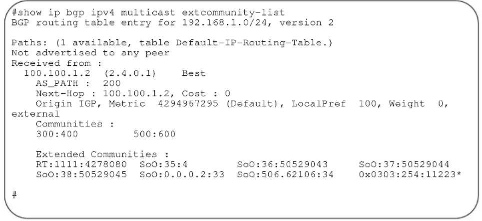
Command History
Version 7.8.1.0 Introduced on S-Series
Version 7.7.1.0 Introduced on C-Series
Version 7.6.1.0 Introduced on E-Series
show ip bgp paths extcommunity

Use this feature to display all BGP paths having extended community attributes.
Syntax
show ip bgp paths extcommunity
Command Modes
EXEC
EXEC Privilege
Example
Figure 12-35. Command Example: show ip bgp paths community (Partial)
| #show ip bgp paths extcommunityTotal 1 Extended Communities | |||
| Address | Hash | Refcount | Extended Community |
| 0x41d57024# | 12272 | 1 | RT:7:200 SoO:5:300 SoO:0.0.0.3:1285 |
Table 12-20. Command Example fields: show ip bgp paths community
| Field Description | |
| Address Displays the internal address where the path attribute is stored. | |
| Hash Displays the hash bucket where the path attribute is stored. | |
| Recount Displays the number of BGP routes using these extended communities. | |
| Community Displays the extended community attributes in this BGP path. | |
Command History
Version 7.8.1.0 Introduced on S-Series
Version 7.7.1.0 Introduced on C-Series
Version 7.6.1.0 Introduced on E-Series
show ip extcommunity-list

Display the IP extended community list.
Syntax
show ip extcommunity-list [word]
Parameters
word
Enter the name of the extended community list you want to view.
Defaults
Defaults.
Command Modes
EXEC
EXEC Privilege
Example
Figure 12-36. Command Example: show ip extcommunity-list
#show ip extcommunity-list test
ip extcommunity-list test
deny RT:1234:12
permit regexp 123
deny regexp 234
deny regexp 123
#
Command History
Version 7.8.1.0 Introduced on S-Series
Version 7.7.1.0 Introduced on C-Series
Version 7.6.1.0 Introduced on E-Series
show running-config extcommunity-list

Use this feature to display the current configuration of the extended community lists.
Syntax
show running-config extcommunity-list [word]
Parameters
word
Enter the name of the extended community list you want to view.
Defaults
No default values or behavior
Command Modes
EXEC Privilege
Example
Figure 12-37. Command Example: show running-config extcommunity-list
#show running-config extcommunity-list test
ip extcommunity-list test
    permit rt 65033:200
    deny soo 101.11.11.2:23
    permit rt as4 110212:340
    deny regex ^(65001_)$
#
Command History
Version 7.8.1.0 Introduced on S-Series
Version 7.7.1.0 Introduced on C-Series
Version 7.6.1.0 Introduced on E-Series
Content Addressable Memory (CAM) for ExaScale
Overview
This chapter discusses CAM commands for the E-Series ExaScale × platform. Refer to Chapter 14, Content Addressable Memory (CAM) for information on the commands for the E-Series TeraScale platform

Warning: If you are using these features for the first time, contact the Dell Force10 Technical Assistance Center (TAC) for guidance. For information on contacting Dell Force10 TAC, visit the Dell Force10 website at www.force10networks.com/support
Commands
This chapter includes the following commands:
• cam-profile template [10M-CAM]
- enable
- flow
- layer-2
- layer-3
- microcode
• show cam-profile
- test cam-profile
Important Points to Remember
- The Default CAM-profile is supported on E-Series ExaScale with FTOS version 8.1.1.0 and later.
- The recommended, pre-defined CAM-profile templates are supported on E-Series ExaScale with FTOS version 8.2.1.0 and later.
- The CAM-profile template is applied to entire system. You must save the running-configuration to enable the change. Saving the running-configuration also ensures that the CAM-profile selected remains in the case of a reboot.
- All components in the chassis must have the same CAM-profile and microcode. The profile and microcode loaded on the primary RPM determines the profile that is required on all other chassis components.
- If a newly installed line card has a profile different from the primary RPM, the card reboots so that it can load the proper profile.
- If the standby RPM has a profile different from the primary RPM, the RPM reboots so that it can load the proper profile.
- Enabling a CAM-profile immediately replaces the existing CAM-profile. You will be prompted to save the running-configuration and reload the system to implement the new CAM-profile.
The CAM-profile commands are:
cam-profile template [10M-CAM]
![DELL Force10 S50-01-GE-48T-V - cam-profile template [10M-CAM] - 1](/content/2026/05/838261/images/c2683152ea9aa96b5d26d6e40418eb04a955bfa70ab2fcbfedcbef734b84995f.jpg)
Select a pre-defined CAM-profile template or create a new CAM-profile template.
Syntax cam-profile template {10M-CAM}
| Parameters | template | Choose one of the following CAM profiles:10M L2 to support IPv4 Layer 2 switching on line cards with 10M CAM.10M L2 IPv6 Switching to support IPv6 Layer 2 switching on line cards with 10M CAM.40M L2 IPv6-IPv4 to support IPv4 and IPv6 Layer 2 routing on line cards with 40M CAM.40M L2 IPv4Only to support IPv4 Layer 2 routing on line cards with 40M CAM.VRF to support Virtual Routing and Forwarding (VRF).MAX-IPv4-FIB to allocate the maximum space supported for IPv4 FIB support.Enter a 16 character string used as a template name to create a new template. |
| Defaults | Default | |
| Command Modes | CONFIGURATION | |
| Command History | Version 8.2.1.0 Introduced on E-Series ExaScale | |
Usage Information
CAM profile changes take effect after the next chassis reboot.
CAM-profile template region allocations are not automatically configured when you select a template. Use the allocations shown in the Content Addressable Memory for ExaScale chapter in the FTOS Configuration Guide for detailed values supported in each CAM/SRAM region.
enable

Enable CAM-profile template.
Syntax
enable
Defaults
cam-profile default microcode default
Command Modes
CONFIGURATION-CAM-profile-template
Command History
Version 8.2.1.0 Introduced on E-Series ExaScale
Usage Information
You must save the running configuration using the command copy running-config startup-config after changing the CAM-profile. CAM-profile template changes take effect after the next chassis reboot.
flow

Configure the Flow region for a CAM-profile template
Syntax
flow [ipv4 | ipv6] multicast-fib {value} pbr {value} qos {value} system-flow {value}
Defaults
None
Command Modes
CONFIGURATION-CAM-profile-template
Command History
Version 8.2.1.0 Introduced on E-Series ExaScale
Usage Information
You do not need to enter every parameter for a region. You can enter only the ones you need.
User configured CAM-profiles are automatically validated.
Refer to Chapter 11, Content Addressable Memory for ExaScale in the FTOS Configuration Guide for detailed values supported in each CAM/SRAM region.
layer-2
| E× | Configure the Layer 2 region for a CAM-profile template |
| Syntax | layer-2 eg-acl {value} fib {value} frrp {value} ing-acl {value} learn {value} l2pt {value} qos {value} system-flow {value} |
| Defaults | None |
| Command Modes | CONFIGURATION-CAM-profile-template |
| Command History | Version 8.2.1.0 Introduced on E-Series ExaScale |
| Usage Information | You do not need to enter every parameter for a region. You can enter only the ones you need.User configured CAM-profiles are automatically validated.Refer to Chapter 11, Content Addressable Memory for ExaScale in the FTOS Configuration Guide for detailed values supported in each CAM/SRAM region. |
| layer-3 | |
| E× | Configure the Layer 3 region for a CAM-profile template |
| Syntax | layer-3 [ipv4 | ipv6] eg-acl {value} fib {value} ing-acl {value} |
| Defaults | None |
| Command Modes | CONFIGURATION-CAM-profile-template |
| Command History | Version 8.2.1.0 Introduced on E-Series ExaScale |
| Usage Information | You do not need to enter every parameter for a region. You can enter only the ones you need.User configured CAM-profiles are automatically validated.Refer to Chapter 11, Content Addressable Memory for ExaScale in the FTOS Configuration Guidefor detailed values supported in each CAM/SRAM region. |
microcode

Assign the microcode to the created CAM-profile template
Syntax
microcode {default | ipv6-switched | lag-hash-align | vrf}
Parameters
| default | Distributes CAM space for a typical deployment.• Applies to the Default CAM-profile and the recommended CAM-profile templates.• Recommended for any user-defined CAM-profiles. |
| vrf Distributes space to best manage IPv4 and IPv6 VRF packet forwarding• Applies to the VRF CAm-profile tEmplate only. | |
| lag-hash-align | |
| ipv6-switched | |
Defaults
None
Command Modes
CONFIGURATION-CAM-profile-template
Command History
Version 8.2.1.0 Introduced on E-Series ExaScale
Usage Information
You must assign a microcode to a CAM-profile template.
IPv6 is not supported with VRF microcode on ExaScale.
show cam-profile

Display the details of the CAM-profiles on the chassis and all line cards.
Syntax
show cam-profile [profile microcode microcode | summary]
| Parameters | profile | (OPTIONAL) Choose a single CAM profile to display: |
| summary | (OPTIONAL) Enter this keyword to view a summary listing of the CAM-profile and on the chassis and all line cards. | |
| Defaults | None | |
| hand Modes | EXEC Privilege | |
| Command History | Version 8.2.1.0 Introduced on E-Series ExaScale | |
Defaults
Command Modes
Example
Figure 13-1. Command Output: show cam-profile summary
| Force10#show cam-profile summary | |
| -- Chassis CAM Profile -- | |
| CamSize : 40-Meg | |
| : Current Settings | |
| Profile Name : default | |
| Microcode Name : Default | |
| -- Line card 2 - per Port Pipe -- | |
| CamSize : 40-Meg | |
| : Current Settings | |
| Profile Name : default | |
| Microcode Name : Default | |
| Force10 | |
Example 2
Figure 13-2. Command Output: show cam-profile
Force10#show cam-profile
-- Chassis CAM Profile --
CamSize : 40-Meg
: Current Settings
Profile Name : default
Microcode Name : Default
L2FIB : 15K entries
Learn : 1K entries
L2ACL : 5K entries
System Flow : 102 entries
Qos : 500 entries
Frrp : 102 entries
L2pt : 266 entries
IPv4FIB : 512K entries
IPv4ACL : 16K entries
IPv4Flow : 24K entries
Mcast Fib/Acl : 9K entries
Pbr : 1K entries
Qos : 10K entries
System Flow : 4K entries
EgL2ACL : 2K entries
EgIPv4ACL : 4K entries
Mpls : 60K entries
IPv6FIB : 12K entries
IPv6ACL : 6K entries
IPv6Flow : 6K entries
Mcast Fib/Acl : 3K entries
Pbr : 0K entries
Qos : 1K entries
System Flow : 2K entries
EgIPv6ACL : 1K entries
GenEgACL : 0.5K entries
IPv4FHOP : 4K entries
IPv6FHOP : 4K entries
IPv4/IPv6NHOP : 12K entries
MPLS LSP Count : 0K entries
EoMPLS Encap : 0K entries
EoMPLS Decap : 0K entries

-- Line card 2 - per Port Pipe --
CamSize : 40-Meg
: Current Settings
Profile Name : default
Microcode Name : Default
L2FIB : 15K entries
Learn : 1K entries
L2ACL : 5K entries
System Flow : 102 entries
Qos : 500 entries
Frrp : 102 entries
L2pt : 266 entries
IPv4FIB : 512k entries
IPv4ACL : 16k entries
IPv4Flow : 24k entries
Mcast Fib/Acl : 9k entries
Pbr : 1K entries
Qos : 10K entries
System Flow : 4K entries

----output truncated----
Force10#
test cam-profile

Validate a user-defined CAM-profile template.
Syntax test cam-profile template
| Parameters | template | Enter the name of the CAM-profile template to validate. |
| Defaults | None | |
| mand Modes | CONFIGURATION-CAM-profile-template | |
| Command History | Version 8.2.1.0 Introduced on E-Series ExaScale | |
Example
| Force10#test cam-profile test |
| cam-profile 'test' can be applied to the system. |
| Force10#test cam-profile Customer002 |
| % Error: 'test cam-profile Customer002 failed. Please check all profile parameters. |
| Force10 |
Content Addressable Memory (CAM)
Overview
Content Addressable Memory (CAM) commands are supported C-Series, E-Series TeraScale and S-Series, as indicated by the symbols under each command heading: C E T S
This chapter includes information relating to the E-Series TeraScale platform. Refer to Chapter 13, Content Addressable Memory (CAM) for ExaScale for information on the commands for the E-Series ExaScale platform.

Note: Not all CAM commands are supported on all platforms. Be sure to note the platform symbol when looking for a command.

Warning: If you are using these features for the first time, contact the Dell Force10 Technical Assistance Center (TAC) for guidance. For information on contacting Dell Force10 TAC, visit the Dell Force10 website at www.force10networks.com/support
This chapter includes the following sections:
• CAM Profile Commands
• CAM IPv4flow Commands
• CAM Layer 2 ACL Commands
CAM Profile Commands
The CAM profiling feature enables you to partition the CAM to best suit your application. For example:
- Configure more Layer 2 FIB entries when the system is deployed as a switch.
- Configure more Layer 3 FIB entries when the system is deployed as a router.
- Configure more ACLs (when IPv6 is not employed).
- Hash MPLS packets based on source and destination IP addresses for LAGs.
- Hash based on bidirectional flow for LAGs.
- Optimize the VLAN ACL Group feature, which permits group VLANs for IP egress ACLs.
Important Points to Remember
- CAM Profiles are available on FTOS versions 6.3.1.1 and later for the E-Series TeraScale. Refer to Chapter 13, Content Addressable Memory (CAM) for ExaScale for information on the commands for the E-Series ExaScale platform.
- FTOS versions 7.8.1.0 and later support CAM allocations on the C-Series and S-Series.
- All line cards within a single system must have the same CAM profile (including CAM sub-region configurations); this profile must match the system CAM profile (the profile on the primary RPM).
- FTOS automatically reconfigures the CAM profile on line cards and the secondary RPM to match the system CAM profile by saving the correct profile on the card and then rebooting it.
- The CAM configuration is applied to entire system when you use CONFIGURATION mode commands. You must save the running-configuration to affect the change.
- When budgeting your CAM allocations for ACLs and QoS configurations, remember that ACL and QoS rules might consume more than one CAM entry depending on complexity. For example, TCP and UDP rules with port range options might require more than one CAM entry.
- After you install a secondary RPM, copy the running-configuration to the startup-configuration so that the new RPM has the correct CAM profile.
- You MUST save your changes and reboot the system for CAM profiling or allocations to take effect.
The CAM Profiling commands are:
- cam-acl (Configuration)
• cam-acl (EXEC Privilege) - cam-optimization
- cam-profile (Config)
• show cam-acl
• show cam-profile
• show cam-usage - test cam-usage
cam-acl (Configuration)

Allocate CAM for IPv4 and IPv6 ACLs
Syntax
cam-acl {default | l2acl number ipv4acl number ipv6acl number, ipv4qos number l2qos number, l2pt number ipmacacl number ecfmacl number [vman-qos | vman-dual-qos number}
Parameters
| default | Use the default CAM profile settings, and set the CAM as follows. • L3 ACL (ipv4acl): 6 • L2 ACL(l2acl): 5 • IPv6 L3 ACL (ipv6acl): 0 • L3 QoS (ipv4qos): 1 • L2 QoS (l2qos): 1 |
| l2acl number ipv4acl number ipv6acl number, ipv4qos number l2qos number, l2pt number ipmacacl number ecfmacl number [vman-qos | vman-dual-qos number | Allocate space to each CAM region. Enter the CAM profile name followed by the amount to be allotted. The total space allocated must equal 13. The ipv6acl range must be a factor of 2. |
Command Modes
CONFIGURATION
Command History
Version 8.3.1.0
Added ecfmacl, vman-qos, and vman-dual-qos keywords.
Version 8.2.1.0 Introduced on the S-Series
Version 7.8.1.0 Introduced on the C-Series
Usage Information
You must save the new CAM settings to the startup-config (write-mem or copy run start) then reload the system for the new settings to take effect.
The total amount of space allowed is 16 FP Blocks. System flow requires 3 blocks and these cannot be reallocated.
When configuring space for IPv6 ACLs, the total number of Blocks must equal 13.
Ranges for the CAM profiles are 1-10, except for the ipv6acl profile which is 0-10. The ipv6acl allocation must be a factor of 2 (2, 4, 6, 8, 10).
cam-acl (EXEC Privilege)

Adjust line card CAM setting to match chassis settings.
This command is deprecated as of FTOS 8.3.1.0
Syntax
cam-acl {chassis |linecard}
Command Modes
EXEC Privilege
Command History
Version 8.3.1.0 COMMAND DEPRECATED
Version 7.8.1.0 Introduced on the C-Series
cam-optimization

Optimize CAM utilization for QoS Entries by minimizing require policy-map CAM space.
Syntax
cam-optimization [qos]
Parameters
qos
Optimize CAM usage for Quality of Service (QoS)
Command Modes
CONFIGURATION
Defaults
Disabled
Command History
Version 8.2.1.0 Introduced on the s-Series
Version 7.8.1.0 Introduced on the C-Series and S-Series
Usage Information
When this command is enabled, if a Policy Map containing classification rules (ACL and/or dscp/ip-precedence rules) is applied to more than one physical interface on the same port pipe, only a single copy of the policy will be written (only 1 FP entry will be used).
Note that an ACL itself may still require more that a single FP entry, regardless of the number of interfaces. Refer to IP Access Control Lists, Prefix Lists, and Route-map in the FTOS Configuration Guide for complete discussion.
cam-profile (Config)

Set the default CAM profile and the required microcode.
Syntax
cam-profile profile microcode microcode
Parameters
| profile | Choose one of the following CAM profiles:Enter the keyworddefaultto specify the default CAM profile.Enter the keywordeg-defaultto specify the default CAM profile for EG (dual-CAM) line cards.Enter the keywordipv4-320kto specify the CAM profile that provides 320K entries for the IPv4 Forwarding Information Base (FIB).Enter the keyword ipv4-egacl-16k to specify the CAM profile that provides 16K entries for egress ACLs.Enter the keyword ipv6-extacl to specify the CAM profile that provides IPv6 functionality.Enter the keyword l2-ipv4-inacl to specify the CAM profile that provides 32K entries for ingress ACLs.Enter the keyword unified-default to specify the CAM profile that maintains the CAM allocations for the IPv6 and IPv4 FIB while allocating more CAM space for the Ingress and Egress Layer 2 ACL, and IPv4 ACL regions.Enter the keyword ipv4-vrf to specify the CAM profile that maintains the CAM allocations for the IPv4 FIB while allocating CAM space for VRF.Enter the keyword ipv4-v6-vrf to specify the CAM profile that maintains the CAM allocations for the IPv4 and IPv6FIB while allocating CAM space for VRF.Enter the keyword ipv4-64k-ipv6 to specify the CAM profile that provides an alternate to ipv6-extacl that redistributes CAM space from the IPv4FIB to IPv4Flow and IPv6FIB. |
| microcode microcode | Choose a microcode based on the CAM profile you chose. Not all microcodes are available to be paired with a CAM profile.Enter the keyworddefaultto select the microcode that distributes CAM space for a typical deployment.Enter the keywordlag-hash-align to select the microcode for applications that require the same hashing for bi-directional traffic.Enter the keyword lag-hash-mpls to select the microcode for hashing based on MPLS labels (up to five labels deep).Enter the keyword ipv6-extacl to select the microcode for IPv6.Enter the keyword acl-group to select the microcode for applications that need 16k egress IPv4 ACLs.Enter the keyword ipv4-vrf to select the microcode for IPv4 VRF applications.Enter the keyword ipv4-v6-vrf to select the microcode for IPv4 and IPv6 VRF applications.E-Series TeraScale only: Select l2-switched-pbr microcode if you apply a PBR redirect list to a VLAN interface and want to prevent Layer 2 traffic from being redirected and dropped. l2-switched-pbr (IPv4-LDA) microcode allows only Layer 3 traffic to be redirected while Layer 2 traffic is switched within the VLAN. |
Defaults
cam-profile default microcode default
Command Modes
CONFIGURATION
| Command History | Version 8.4.1.0 Added support for l2-switched-pbr microcode. |
| Version 8.2.1.0 Added support for the ipv4-64k-ipv6 profile. | |
| Version 7.9.1.0 Added support for VRF protocols. | |
| Version 7.5.1.0 Added the l2-ipv4-inacl CAM profile | |
| Version 7.4.2.0 Added the unified-default CAM profile and lag-hash-align microcode | |
| Version 7.4.1.0 Added the lag-hash-mpls microcode | |
| Version 6.5.1.0 Added the eg-default and ipv4-320k CAM profiles | |
| Version 6.3.1.0 Introduced on E-Series |
Usage Information You must save the running configuration using the command copy running-config startup-config after changing the CAM profile from CONFIGURATION mode. CAM profile changes take effect after the next chassis reboot.

Note: Do not use the ipv4-egacl-16 CAM profile for Layer 2 egress ACLs.

Note: Do not make any changes to the CAM profile after you change the profile to ipv4-320K and save the configuration until after you reload the chassis; any changes lead to unexpected behavior. After you reload the chassis, you may make changes to the IPv4 Flow partition.
show cam-acl

Display the details of the CAM profiles on the chassis and all line cards.
Syntax
show cam-acl
Defaults
None
Command Modes
EXEC Privilege
Command History
Version 7.8.1.0 Introduced on C-Series
Usage Information
The display reflects the settings implemented with the cam-acl command.
Example
Figure 14-1. Command Output: show cam-acl (default)
Force10#show cam-acl
-- Chassis Cam ACL --
Current Settings(in block sizes)
L2Acl : 5
Ipv4Acl : 6
Ipv6Acl : 0
Ipv4Qos : 1
L2Qos : 1
-- Line card 4 --
Current Settings(in block sizes)
L2Acl : 5
Ipv4Acl : 6
Ipv6Acl : 0
Ipv4Qos : 1
L2Qos : 1
Force10#
Figure 14-2. Command Output: show cam-acl (non-default)
Force10#show cam-acl
-- Chassis Cam ACL --
Current Settings(in block sizes)
L2Acl : 2
Ipv4Acl : 2
Ipv6Acl : 4
Ipv4Qos : 2
L2Qos : 3
-- Line card 4 --
Current Settings(in block sizes)
L2Acl : 2
Ipv4Acl : 2
Ipv6Acl : 4
Ipv4Qos : 2
L2Qos : 3
Force10#
show cam-profile
E Display the details of the CAM profiles on the chassis and all line cards.
Syntax show cam-profile [profile microcode microcode | summary]
| Parameters | profile | (OPTIONAL) Choose a single CAM profile to display:Enter the keyworddefaultto specify the default CAM profile.Enter the keywordeg-defaultto specify the default CAM profile for EG (dual-CAM) line cards.Enter the keywordipv4-320kto specify the CAM profile that provides 320K entries for the IPv4 Forwarding Information Base (FIB).Enter the keywordipv4-egacl-16kto specify the CAM profile that provides 16K entries for egress ACLs.Enter the keyword ipv6-extaclto specify the CAM profile that provides IPv6 functionality.Enter the keywordl2-ipv4-inaclto specify the CAM profile that provides 32K entries for ingress ACLs.Enter the keywordunified-defaultto specify the CAM profile that maintains the CAM allocations for the IPv6 and IPv4 FIB while allocating more CAM space for the Ingress and Egress Layer 2 ACL, and IPv4 ACL regions.Enter the keywordipv4-vrfto specify the CAM profile that maintains the CAM allocations for the IPv4 FIB while allocating CAM space for VRF.Enter the keywordipv4-v6-vrfto specify the CAM profile that maintains the CAM allocations for the IPv4 and IPv6FIB while allocating CAM space for VRF. |
| microcodemicrocode | Choose the microcode to display. Not all microcodes are available to be paired with a CAM profile.Enter the keyworddefaultto select the microcode that distributes CAM space for a typical deployment.Enter the keywordlag-hash-alignto select the microcode for applications that require the same hashing for bi-directional traffic.Enter the keywordlag-hash-mplsto select the microcode for hashing based on MPLS labels (up to five labels deep).Enter the keywordipv6-extaclto select the microcode for IPv6.Enter the keywordacl-groupto select the microcode for applications that need 16k egress IPv4 ACLs.Enter the keywordipv4-vrfto select the microcode for IPv4 VRF applications.Enter the keywordipv4-v6-vrfto select the microcode forIPv4 and IPv6 VRF applications.Enter the keywordipv4-64k-ipv6to specify the CAM profile that provides an alternate to ipv6-extacl that redistributes CAM space from the IPv4FIB to IPv4Flow and IPv6FIB. | |
| summary | (OPTIONAL) Enter this keyword to view a summary listing of the CAM profile and microcode on the chassis and all line cards. |
| Defaults | None |
| Command Modes | EXEC Privilege |
Command History
| Version 8.2.1.0 Added support for ipv4-64k-ipv6 profile |
| Version 7.9.1.0 Added support for VRF protocols. |
| Version 6.3.1.0 Introduced on E-Series |
Usage Information If the CAM profile has been changed, this command displays the current CAM profile setting in one column and in the other column displays the CAM profile and the microcode that will be configured for the chassis and all online line cards after the next reboot.
Example 1 Figure 14-3. Command Output: show cam-profile summary
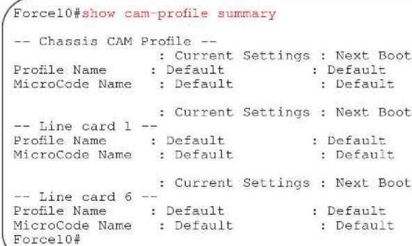
Example 2 Figure 14-4. Command Output: show cam-profile
| CamSize | : 18-Meg | |
| : Current Settings : Next Boot | ||
| Profile Name | : DEFAULT | : DEFAULT |
| L2FIB | : 32K entries | : 32K entries |
| L2ACL | : 1K entries | : 1K entries |
| IPv4FIB | : 256K entries | : 256K entries |
| IPv4ACL | : 12K entries | : 12K entries |
| IPv4Flow | : 24K entries | : 24K entries |
| EgL2ACL | : 1K entries | : 1K entries |
| EgIPv4ACL | : 1K entries | : 1K entries |
| Reserved | : 8K entries | : 8K entries |
| IPv6FIB | : 0 entries | : 0 entries |
| IPv6ACL | : 0 entries | : 0 entries |
| IPv6Flow | : 0 entries | : 0 entries |
| EgIPv6ACL | : 0 entries | : 0 entries |
| MicroCode Name | : Default | : Default |
| -- Line card 0 -- | ||
| CamSize | : 18-Meg | |
| : Current Settings : Next Boot | ||
| Profile Name | : DEFAULT | : DEFAULT |
| L2FIB | : 32K entries | : 32K entries |
| L2ACL | : 1K entries | : 1K entries |
| IPv4FIB | : 256K entries | : 256K entries |
| IPv4ACL | : 1.2K entries | : 1.2K entries |
| IPv4Flow | : 24K entries | : 24K entries |
| EgL2ACL | : 1K entries | : 1K entries |
| EgIPv4ACL | : 1K entries | : 1K entries |
| Reserved | : 8K entries | : 8K entries |
| IPv6FIB | : 0 entries | : 0 entries |
| IPv6ACL | : 0 elements | : 0 entries |
| IPv6Flow | : 0 entries | : 0 entries |
| EgIPv6ACL | : 0 entries | : 0 entries |
| MicroCode Name | Default | Default |
show cam-usage
E Display Layer 2, Layer 3, ACL, or all CAM usage statistics.
Syntax show cam-usage [acl | router | switch]
Parameters
| acl | (OPTIONAL) Enter this keyword to display Layer 2 and Layer 3 ACL CAM usage. |
| router | (OPTIONAL) Enter this keyword to display Layer 3 CAM usage. |
| switch | (OPTIONAL) Enter this keyword to display Layer 2 CAM usage. |
Defaults
None
Command Modes
EXEC Privilege
Command History
Version 6.5.1.0 Introduced on E-Series
Example
Figure 14-5. Command Example: show cam-usage
| Force10#show cam -usage | |||||
| Linecard | Portpipe | CAM Partition | Total CAM | Used CAM | Available CAM |
| 1 | 0 | IN-L2 ACL | 1008 | 320 | 688 |
| IN-L2 FIB | 32768 | 1132 | 31636 | ||
| IN-L3 ACL | 12288 | 2 | 12286 | ||
| IN-L3 FIB | 262141 | 14 | 262127 | ||
| IN-L3-SysFlow | 2878 | 45 | 2833 | ||
| IN-L3-TrcList | 1024 | 0 | 1024 | ||
| IN-L3-McastFib | 9215 | 0 | 9215 | ||
| IN-L3-Qos | 8192 | 0 | 8192 | ||
| IN-L3-PBR | 1024 | 0 | 1024 | ||
| IN-V6 ACL | 0 | 0 | 0 | ||
| IN-V6 FIB | 0 | 0 | 0 | ||
| IN-V6-SysFlow | 0 | 0 | 0 | ||
| IN-V6-McastFib | 0 | 0 | 0 | ||
| OUT-L2 ACL | 1024 | 0 | 1024 | ||
| OUT-L3 ACL | 1024 | 0 | 1024 | ||
| OUT-V6 ACL | 0 | 0 | 0 | ||
| 1 | 1 | IN-L2 ACL | 320 | 0 | 320 |
| IN-L2 FIB | 32768 | 1136 | 31632 | ||
| IN-L3 ACL | 12288 | 2 | 12286 | ||
| IN-L3 FIB | 262141 | 14 | 262127 | ||
| IN-L3-SysFlow | 2878 | 44 | 2834 | ||
Example
Figure 14-6. Command Example: show cam-usage acl
| Force10#show cam-usage acl | |||||
| Linecard | Portpipe | CAM Partition | Total CAM | Used CAM | Available CAM |
| 11 | 0 | IN-L2 ACL | 1008 | 0 | 1008 |
| IN-L3 ACL | 12288 | 2 | 12286 | ||
| OUT-L2 ACL | 1024 | 2 | 1022 | ||
| OUT-L3 ACL | 1024 | 0 | 1024 | ||
| Force10# | |||||
Example
Figure 14-7. Command Example: show cam-usage router
| Linecard | Portpipe | CAM Partition | Total CAM | Used CAM | Available CAM |
| 11 | 0 | IN-L3 ACL | 8192 | 3 | 8189 |
| IN-L3 FIB | 196607 | 1 | 196606 | ||
| IN-L3-SysFlow | 2878 | 0 | 2878 | ||
| IN-L3-TrcList | 1024 | 0 | 1024 | ||
| IN-L3-McastFib | 9215 | 0 | 9215 | ||
| IN-L3-Qos | 8192 | 0 | 8192 | ||
| IN-L3-PBR | 1024 | 0 | 1024 | ||
| OUT-L3 ACL | 16384 | 0 | 16384 | ||
| 11 | 1 | IN-L3 ACL | 8192 | 3 | 8189 |
| IN-L3 FIB | 196607 | 1 | 196606 | ||
| IN-L3-SysFlow | 2878 | 0 | 2878 | ||
| IN-L3-TrcList | 1024 | 0 | 1024 | ||
| IN-L3-McastFib | 9 215 | 0 | 9215 | ||
| IN-L3-Qos | 8192 | 0 | 8192 | ||
| IN-L3-PBR | 1024 | 0 | 1024 | ||
| OUT-L3 ACL | 16384 | 0 | 16384 |
Example
Figure 14-8. Command Example: show cam-usage switch
| Force10#show cam-usage switch | |||||
| Linecard | Portpipe | CAM Partition | Total CAM | Used CAM | Available CAM |
| 11 | 0 | IN-L2 ACL | 7152 | 0 | 7152 |
| IN-L2 FIB | 32768 | 1081 | 31687 | ||
| OUT-L2 ACL | 0 | 0 | 0 | ||
| 11 | 1 | IN-L2 ACL | 7152 | 0 | 7152 |
| IN-L2 FIB | 32768 | 1081 | 31687 | ||
| OUT-L2 ACL | 0 | 0 | 0 | ||
| Force10# | |||||
test cam-usage

Verify that enough CAM space is available for the IPv6 ACLs you have created.
Syntax
test cam-usage service-policy input input policy name linecard {number | all}
Parameters
| policy-map name | Enter the name of the policy-map to verify. |
| number | Enter all to get information for all the linecards/stack-units, or enter the linecard/ stack-unit number to get information for a specific card. Range: 0-6 for E-Series, 0-7 for C-Series, 0-7 for S-Series |
Defaults
None
Command Modes
EXEC Privilege
Command History
Version 7.8.1.0 Introduced
Usage Information
This command applies to both IPv4 and IPv6 CAM Profiles, but is best used when verifying QoS optimization for IPv6 ACLs.
QoS Optimization for IPv6 ACLs does not impact the CAM usage for applying a policy on a single (or the first of several) interfaces. It is most useful when a policy is applied across multiple interfaces; it can reduce the impact to CAM usage across subsequent interfaces.
Example The following examples show some sample output when using the test cam-usage command.
Figure 14-9. Command Example: test cam-usage (C-Series)
| Force10#test cam-usage service-policy input LauraMapTest linecard all | |||||
| Linecard | Portpipe | CAM Partition | Available CAM | Estimated CAM per Port | Status |
| 2 | 1 | IPv4Flow | 232 | 0 | Allowed |
| 2 | 1 | IPv6Flow | 0 | 0 | Allowed |
| 4 | 0 | IPv4Flow | 232 | 0 | Allowed |
| 4 | 0 | IPv6Flow | 0 | 0 | Allowed |
| Force10# | |||||
| Force10#test cam-usage service-policy input LauraMapTest linecard 4 port-set 0 | |||||
| Linecard | Portpipe | CAM Partition | Available CAM | Estimated CAM per Port | Status |
| 4 | 0 | IPv4Flow | 232 | 0 | Allowed |
| 4 | 0 | IPv6Flow | 0 | 0 | Allowed |
| Force10# | |||||
| Force100#test cam-usage service-policy input LauraMapTest linecard 2 port-set 1 | |||||
| Linecard | Portpipe | CAM Partition | Available CAM | Estimated CAM per Port | Status |
| 2 | 1 | IPv4Flow | 232 | 0 | Allowed |
| 2 | 1 | IPv6Flow | 0 | 0 | Allowed |
| Force10# | |||||
Table 14-1. Output Explanations: test cam-usage (C-Series)
| Term Explanation | |
| Linecard | Lists the line card or linecards that are checked. Entering all shows the status for linecards in the chassis |
| Portpipe Lists the portpipe (port-set) or | port pipes (port-sets) that are checked. Entering all shows the status for linecards and port-pipes in the chassis. |
| CAM Partition Shows the CAM profile | of the CAM |
| Available CAM Identifies the amount of CAM space remaining for that profile | |
| Estimated CAM per Port Estimates the amount of CAM space the listed policy will require. | |
| Status Indicates whether or not the policy will be allowed in the CAM | |
Figure 14-10. Command Example: test cam-usage (S-Series)

Table 14-2. Output Explanations: test cam-usage (S-Series)
| Term Explanation | |
| Stack-Unit | Lists the stack unit or units that are checked. Entering all shows the status for all stacks. |
| Portpipe Lists the portpipe (port-set) or | port pipes (port-sets) that are checked. Entering all shows the status for linecards and port-pipes in the chassis. |
| CAM Partition Shows the CAM profile | of the CAM |
| Available CAM Identifies the amount of CAM space remaining for that profile | |
| Estimated CAM per Port Estimates the amount of CAM space the listed policy will require. | |
| Status Indicates whether or not the policy will be allowed in the CAM | |
CAM IPv4flow Commands
IPv4Flow sub-partitions are supported on E-Series TeraScale platform
The 18-megabit user configurable CAM is divided into multiple regions such as Layer 2 FIB, Layer 3 FIB, IPv4Flow, IPv4 Ingress ACL, etc. The IPv4Flow region is further sub-divided into 5 regions: System Flow, QoS, PBR, Trace-lists, Multicast FIB & ACL.
You can change the amount of CAM space allocated to each sub-region. You can configure the IPv4Flow region in both EtherScale and TeraScale. In EtherScale, these commands allocate CAM space for IPv4Flow sub-regions and the IPv4 ACL region.
Like CAM profiles, you can configure the IPv4Flow region from EXEC Privilege and CONFIGURATION mode.
The CAM IPv4flow commands are:
• cam ipv4flow (EXEC Privilege)
• cam-ipv4flow (CONFIGURATION)
• show cam-ipv4flow
cam ipv4flow (EXEC Privilege)

Configure the amount of CAM space in IPv4flow sub-regions.
This command is deprecated as of FTOS 8.3.1.0
Syntax
cam ipv4flow {chassis all | linecard number} {default | acl value multicast-fib value pbr value qos value system-flow value trace-list value}
Command Modes
EXEC Privilege
Command History
Version 8.3.1.0 COMMAND DEPRECATED
Version 6.3.1.0 Introduced on E-Series
cam-ipv4flow (CONFIGURATION)

Configure the amount of CAM space in IPv4flow sub-regions.
Syntax
cam-ipv4flow {default | multicast-fib value pbr value qos value system-flow value trace-list value}
Parameters
| default | Enter the keyworddefaultto reset the IPV4Flow CAM region to its default setting. |
| multicast-fib value | Enter the keywordmulticast-fibfollowed by the number of entries for the multicast FIB sub-region in 1K increments.Range: 1 to 32 KBDefault: 9 KB |
| pbr value | Enter the keywordpbrfollowed by the number of entries for the PBR sub-region in 1K increments.Range: 1 to 32 KBDefault: 1 KB |
| qos value | Enter the keywordqosfollowed by the number of entries for the QoS sub-region in 1K increments.Range: 1 to 32 KBDefault: 8 KB |
| system-flow value | Enter the keywordsystem-flowfollowed by the number of entries for the system-flow sub-region in 1K increments.Range: 4 to 32 KBDefault: 5 KB |
| trace-list value | Enter the keywordtrace-listfollowed by the number of entries for the trace-list sub-region in 1K increments.Range: 1 to 32 KBDefault: 1 KB |
Defaults
See Parameters
Command Modes
CONFIGURATION
Command History
Version 6.3.1.0 Introduced on E-Series
Usage Information
CAM profile changes take effect after the next chassis reboot.
Related Commands
copy Save the running configuration.
show cam-ipv4flow Display the CAM IPv4flow entries.
show cam-ipv4flow

Display details about the IPv4Flow sub-regions.
Syntax
show cam-ipv4flow
Command Modes
EXEC Privilege
Command History
Version 6.3.1.0 Introduced on E-Series
Example
Figure 14-11. Command Example: show cam-ipv4flow
| Force10#show cam-ipv4flow | |||
| -- Chassis Cam IPv4Flow -- | |||
| Current Settings | Next Boot | ||
| Acl : | 8K | 5K | |
| Multicast Fib/Acl : | 9K | 12K | |
| Pbr : | 1K | 1K | |
| Qos : | 8K | 8K | |
| System Flow : | 5K | 5K | |
| Trace Lists : | 1K | 1K | |
| -- Line card 2 -- | |||
| Current Settings | Next Boot | ||
| Acl : | 5K | 0K | |
| Multicast Fib/Acl : | 9K | 12K | |
| Pbr : | 1K | 1K | |
| Qos : | 8K | 8K | |
| System Flow : | 5K | 5K | |
| Trace Lists : | 1K | 1K | |
| -- Line card 8 -- | |||
| Current Settings | Next Boot | ||
| Acl : | 5K | 0K | |
| Multicast Fib/Acl : | 9K | 12K | |
| Pbr : | 1K | 1K | |
| Qos : | 8K | 8K | |
| System Flow : | 5K | 5K | |
| Trace Lists : | 1K | 1K | |
| -- Line card 13 -- | |||
| Current Settings | Next Boot | ||
| Acl : | 5K | 0K | |
| Multicast Fib/Acl : | 9K | 12K | |
| Pbr : | 1K | 1K | |
| Qos : | 8K | 8K | |
| System Flow : | 5K | 5K | |
| Trace Lists : | 1K | 1K | |
Usage Information
If the IPv4Flow sub-region has been changed, this command displays the current IPv4Flow configuration in one column and in the other column displays the IPv4Flow configuration that will be loaded after the next reboot.
Related Commands
cam-ipv4flow (CONFIGURATION)
Configure the amount of CAM space in IPv4flow sub-regions.
CAM Layer 2 ACL Commands
IPv4Flow sub-partitions are supported on the E-Series TeraScale platform
The CAM Layer 2 ACL commands are:
• cam l2acl (EXEC Privilege)
• cam-12acl (CONFIGURATION)
• show cam-12acl
The 18-megabit user configurable CAM is divided into multiple regions such as Layer 2 FIB, Layer 3 FIB, IPv4Flow, IPv4 Ingress ACL, etc. The Layer 2 ACL region is further sub-divided into 6 regions: Sysflow, L2ACL, PVST, QoS, L2PT, FRRP.
You can change the amount of CAM space, in percentage, allocated to each sub-region. The amount of space that you can distribute to the sub-partitions is equal to the amount of CAM space that the selected CAM profile allocates to the Layer 2 ACL partition. FTOS requires that you specify the amount of CAM space for all sub-partitions and that the sum of all sub-partitions is 100%.
Like CAM profiles, you can configure the Layer 2 ACL partition from EXEC Privilege mode or CONFIGURATION mode.
cam l2acl (EXEC Privilege)

Re-allocate the amount of space, in percentage, for each Layer 2 ACL CAM sub-partition.
This command is deprecated as of FTOS 8.3.1.0
Syntax
cam l2acl {chassis all | linecard number} {default | system-flow percentage l2acl percentage pvst percentage qos percentage l2pt percentage frrp percentage}
Command Modes
EXEC Privilege
Command History
Version 8.3.1.0 COMMAND DEPRECATED
Version 7.7.1.0 Introduced on E-Series
cam-l2acl (CONFIGURATION)

Re-allocate the amount of space, in percentage, for each Layer 2 ACL CAM sub-partition.
Syntax
cam-l2acl {default | system-flow percentage l2acl percentage pvst percentage qos percentage l2pt percentage frrp percentage}
Parameters
| default | Enter this keyword to reset the Layer 2 ACL CAM sub-partition space allocations to the default values (Sysflow: 6, L2ACL: 14, PVST: 50, QoS: 12, L2PT: 13, FRRP: 5). |
| system-flow percentage | Allocate a percentage of the Layer 2 ACL CAM space for system flow entries. Enter the keyword system-flow, and specify the percentage. Range: 5 to 100 |
| l2acl percentage | Allocate a percentage of the Layer 2 ACL CAM space for Layer 2 ACL entries. Enter the keyword l2acl, and specify the percentage. Range: 5 to 95 |
| pvst percentage | Allocate a percentage of the Layer 2 ACL CAM space for PVST+ entries. Enter the keyword pvst and specify the percentage. Range: 5 to 95 |
| qos percentage | Allocate a percentage of the Layer 2 ACL CAM space for QoS entries. Enter the keyword qos, and specify the percentage. Range: 5 to 95 |
| l2pt percentage | Allocate a percentage of the Layer 2 ACL CAM space for L2PT entries. Enter the keyword l2pt, and specify the percentage. Range: 5 to 95 |
| frrp percentage | Allocate a percentage of the Layer 2 ACL CAM space for FRRP entries. Enter the keyword frrp, and specify a percentage. Range: 5 to 95 |
Command Modes
CONFIGURATION
Command History
Version 7.7.1.0 Introduced on E-Series
Usage Information
The PVST sub-partition requires a minimum number of entries when employing PVST+. See the CAM chapter of the FTOS Configuration Guide for the E-Series.
Related Commands
| show cam-l2acl | Display the percentage of the Layer 2 ACL CAM partition that is allocated to each Layer 2 ACL CAM sub-partition. |
show cam-l2acl

Display the percentage of the Layer 2 ACL CAM partition that is allocated to each Layer 2 ACL CAM sub-partition. If configuration has changed, the command displays the current configuration and the configuration that FTOS will write to the CAM after the next chassis reboot.
Syntax
show cam-l2acl
Command Modes
EXEC Privilege
Command History
Version 7.7.1.0 Introduced on E-Series
Example
Figure 14-12. Command Example: show cam-l2acl
Force10#show cam-12acl
-- Chassis Cam L2-ACL --
Current Settings(in percent)
Sysflow : 6
L2Acl : 14
Pvst : 50
Qos : 12
L2pt : 13
Frrp : 5
-- Line card 1 --
Current Settings(in percent)
Sysflow : 6
L2Acl : 14
Pvst : 50
Qos : 12
L2pt : 13
Frrp : 5
-- Line card 5 --
Current Settings(in percent)
Sysflow : 6
L2Acl : 14
--More--
Related Commands
cam-l2acl Re-allocate the amount of space, in percentage, for each Layer 2 ACL CAM (CONFIGURATION) sub-partition.
Configuration Rollback
Overview
The Configuration Rollback feature is enabled on the C-Series and E-Series . Configuration Rollback enables you to archive your running configurations for future use. This feature also enables you to replace your running configuration with an archived running configuration without rebooting the chassis. Once you load an archived configuration, you have the option to confirm the replacement or revert (roll back) to your previous configuration. This rollback feature enables you to view and test a configuration before completing the configuration change.

Note: Archive files are stored on the internal flash in a hidden directory named CFGARCH. You may have to reboot the chassis when rolling back to a feature that explicitly requires it, like CAM profiles.
Commands
The Configuration Rollback commands are:
- archive
- archive backup
- archive config
- archive delete
- configure confirm
- configure replace
- configure terminal
- configuration mode exclusive
- debug rollback
• maximum number
• show archive
• show config
• show configuration lock
• show run diff - time-period
archive

Enter the CONFIGURATION ARCHIVE mode.
Syntax
archive
To exit the CONFIGURATION ARCHIVE mode, use the exit command at the CONFIGURATION ARCHIVE mode prompt (conf-archive).
Defaults
No default values or behavior
Command Modes
CONFIGURATION ARCHIVE (conf-archive)
Command History
Version 7.6.1.0 Introduced on C-Series and E-Series.
Example
Force10#conf
Force10 (conf) #archive
Force10 (conf-archive) #
Force10#
archive backup

Copy an archive file to another location.
Syntax
archive backup {flash://CFGARCH_DIR/filename} {flash://filepath | ftp://userid:password@hostip/filepath}
Parameters
| flash://CFGARCH_DIR/filename | Enter the path directory flash://CFGARCH_DIR/followed by the name of the file. |
| flash://filepath | Enter the path flash:// followed by the file path of the local file system to copy your file to the local location. |
| ftp://userid:password@hostip/filepath | Enter the path ftp:// followed by the FTP remote file system to copy your file to the remote location. |
Defaults
No default values or behavior
Command Modes
EXEC Privilege
Command History
Version 7.6.1.0 Introduced on C-Series and E-Series
Related Commands
show archive Display the archive
archive config

Archive a running configuration.
Syntax
archive config [comment comment]
| Parameters | comment comment | Describe the configuration that you are archiving using up to 30 characters. |
| Defaults | No default values or behavior | |
| mand Modes | EXEC Privilege | |
| Command History | Version 7.7.1.0 Comment option added | |
| Version 7.6.1.0 Introduced on C-Series and E-Series | ||
| Usage Information | Archive files are stored on flash in a hidden directory named CFGARCH. This directory name is a acronym for Configure Archive. A maximum of 15 archive files can be stored in this directory. | |
Defaults
Command History
Usage Information
Example
Figure 15-1. archive config Command Example
| R4_C300#archive config comment 30 characters |
| 3d2h5m: %RPM0-P:CP %CFGARCHIVE-5-RUNNING_CFG Archived: Archived running-config as archive_0 |
| configuration archived as archive_0 |
| R4_C300# |
archive delete

Delete an archived configuration.
Syntax
archive delete {number|all}
Parameters
| number | Specify the which archived configuration you want to delete. |
| all | Enter this keyword to delete all archived configurations. |
Defaults
None
Command Modes
CONFIG ARCHIVE
Command History
Version 7.7.1.0 Introduced on C-Series and E-Series
Example
Figure 15-2. archive delete Command Example
| Force10#archive delete allPlease confirm if you want to proceed [yes/no]:yes all archives have been removed. |
| Force10# |
configure confirm

Confirm the replacement of the running configuration when time option is used with the configure replace command.
Syntax
configure confirm
Defaults
No default values or behavior
Command Modes EXEC Privilege
Command History
Version 7.6.1.0 Introduced on C-Series and E-Series
Related Commands
show archive Display the archive
configure replace

Replace the running configuration with a specified file.
Syntax
configure replace {flash://filepath | startup-config [force | time seconds]}
Parameters
| flash://filepath | Enter the path flash:// followed by the file path of the local file system to copy your file to the local location. |
| startup-config force | Enter the keyword startup-config to replace with the startup configuration and force the replacement without confirmation. |
| force | Enter the keyword force to replace the startup configuration without confirmation. |
| time seconds | Enter the keyword time to replace with the startup configuration and designate the time with which you have to confirm the replacement of the running configuration.Range: 60 to 1800 seconds |
Defaults
No default values or behavior
Command Modes
EXEC Privilege
Command History
Version 7.6.1.0 Introduced on C-Series and E-Series
configure terminal

Enter the exclusive configuration mode when the confutation mode is set to manual.
Syntax
configure terminal [lock]
To undo the lock, use the exit command.
Parameters
lock (OPTIONAL) Enter the keyword lock to lock the confirmation in an exclusive mode.
Defaults
Unlocked
Command Modes
EXEC Privilege
Usage Information
Archiving/replacing a configuration automatically locks CONFIGURATION mode. Use this command when you want exclusive control of CONFIGURATION mode when making configuration changes.
Command History
Version 7.6.1.0 Introduced on C-Series and E-Series
Related Commands
configuration mode exclusive Enable exclusive configuration.
configuration mode exclusive

Enable exclusive configuration mode.
Syntax
configuration mode exclusive {auto | manual}
To negate the configuration, use the no configuration mode exclusive {auto | manual} command.
Parameters
auto Enter auto to set the exclusive mode to auto.
manual
Enter manual to set the exclusive mode to manual (the default).
Defaults
CONFIGURATION mode does not lock by default.
Command Modes
EXEC Privilege
Command History
Version 7.6.1.0 Introduced on C-Series and E-Series
Usage Information
If you choose the manual option, you must enter set the lock each time before entering CONFIGURATION mode.
If you choose the auto option, you can exit to EXEC Privilege mode and re-enter CONFIGURATION mode without setting the lock again.
If another user attempts to enter the CONFIGURATION mode while a lock is in place, the following message is generated:
% Error: User "" on line console0 is in exclusive configuration mode
If a user is already in CONFIGURATION mode when a lock is executed, the following message is generated:
% Error: Can't lock configuration mode exclusively since the following users are currently configuring the system:
User "admin" on line vty1 (10.1.1.1)

Note: The CONFIGURATION mode lock corresponds to a VTY session, not to a user. If you set a lock and then exit the CONFIGURATION mode and another user enters CONFIGURATION mode, you will be denied access when you attempt to re-enter CONFIGURATION mode.
Example
Force10(conf)#configuration mode exclusive auto Force10(conf)#exit 3d23h35m: %RPM0-P:CP %SYS-5-CONFIG_I: Configured from console by console Force10#config! Locks configuration mode exclusively. Force10(conf)#

Note: When your session times out and you return to EXEC mode, the lock is no longer set.
Related Commands
configure terminal When configuration is set to manual, use this command to set the exclusive mode.
debug rollback

Enable debugging for the configuration replace and rollback feature.
Syntax
debug rollback
Disable debugging using the command undebug all.
Defaults
Debugging is disabled for all features by default.
Command Modes
EXEC Privilege
Command History
Version 7.6.1.0 Introduced on C-Series and E-Series
Related Commands
undebug all Disable all debug operations on the system.
maximum number

Set the maximum number of archives.
Syntax
maximum {number}
To return to the default, use the no maximum {number} command.
Parameters
number
Enter the maximum number of files to archive.
Range: 2 to 15
Default: 10
Defaults
No default values or behavior
Command Modes
CONFIGURATION (conf-archive)
Command History
Version 7.6.1.0 Introduced on C-Series and E-Series
Related Commands
show archive Display the archive
show archive

Display the content of the archive.
Syntax
show archive
Defaults
No default values or behavior
Command Modes
EXEC Privilege
Command History
Version 7.6.1.0 Introduced on C-Series and E-Series
Example
Figure 15-3. show archive Command Output
| # | Archive | Date | Time | Size | Comment |
| 0 | - | ||||
| 1 | - | ||||
| 2 | - | ||||
| 3 | - | ||||
| 4 | - | ||||
| 5 | - | ||||
| 6 | - | Deleted | |||
| 7 | *archive_7 | 12/13/2007 | 20:51:24 | 5640 | Archived |
| 8 | archive_8 | 12/13/2007 | 20:51:44 | 5645 | Archived |
| 9 | archive_9 | 12/16/2007 | 21:43:44 | 5677 | Most recently archived |
| 10 | - | ||||
| 11 | - | Deleted | |||
| 12 | - | Deleted | |||
| 13 | - | Deleted | |||
| 14 | - | ||||
| Force10# | |||||
Usage Information
The most recent archived configuration is marked with an asterisk in the output of this command.
show config

Display the contents of the archive configuration.
Syntax
show config
Defaults
No default values or behavior
Command Modes
CONFIGURATION (conf-archive)
Command History
Version 7.6.1.0 Introduced on C-Series and E-Series
Example
Force10# (conf-archive) # show config
!
archive
maximum 3
Force10# (conf-archive) #
show configuration lock

Show the configuration lock status.
Syntax
show configuration lock
Defaults
None
Command Modes
EXEC Privilege
Command History
Version 7.7.1.0 Introduced on C-Series and E-Series
Example
Figure 15-4. show configuration lock Command Output
Force10# show configuration lock
Configure exclusively locked by the following line:
Line : vty 0
Line number : 2
User : admin
Type : AUTO
State : LOCKED
Ip address : 10.11.9.97
Usage Information
The type may be auto, manual, or rollback. When set to auto, FTOS automatically denies access to CONFIGURATION mode to all other users every time the user on the listed VTY line enters CONFIGURATION mode. When set to manual, the user on the listed VTY line must explicitly set the lock each time before entering CONFIGURATION mode. Rollback indicates that FTOS is in a rollback process. The line number shown in the output can be used to send the messages to that session or release a lock on a VTY line.
Related Commands
clear line Reset a terminal line.
configuration mode exclusive Enable exclusive configuration mode.
send Send messages to one or all terminal line users.
show run diff

Display the difference between an archived file and a file.
Syntax
show run diff {flash: | startup-config}
Parameters
| flash: | Enter the archive configuration file using the path [flash://]filename |
| startup-config | Enter the keywords startup-config to compare the contents of the startup configuration. |
Defaults
No default values or behavior
Command Modes
EXEC Privilege
Command History
Version 7.6.1.0 Introduced on C-Series and E-Series
Example
Figure 15-5. show run diff archive Command Example
Force10#show run diff archive_7
running-config
----
< policy-map-input test

running-config
----
< archive

< maximum 3

flash:/CFGARCH_DIR/archive_7
----
> archive

Force10#
time-period

Set a time period to automatically save an archive file.
Syntax
time-period {minutes}
To stop the auto-save, use the no time-period {minutes} command.
Parameters
| minutes | Enter the time, in minutes to automatically save an archive file. Range: 5 to 1440 minutes |
Defaults
Disabled, that is no automatically saving is configured
Command Modes
CONFIGURATION (conf-archive)
Command History
Version 7.6.1.0 Introduced on C-Series and E-Series
Dynamic Host Configuration Protocol (DHCP)
Overview
Dynamic Host Configuration Protocol (DHCP) is an application layer protocol that dynamically assigns IP addresses and other configuration parameters to network end-stations (hosts) based on configuration policies determined by network administrators.
- Commands to Configure the System to be a DHCP Server
- Commands to Configure Secure DHCP
Commands to Configure the System to be a DHCP Server
- clear ip dhcp
- client-identifier
- debug ip dhcp server
- default-router
- disable
- dns-server
- domain-name
- excluded-address
- hardware-address
- host
- ip dhcp bootp
- ip dhcp relay information
- disable
- lease
- netbios-name-server
- netbios-node-type
- network
- pool
• show ip dhcp binding
• show ip dhcp configuration
• show ip dhcp conflict
• show ip dhcp database
• show ip dhcp server
clear ip dhcp

Reset DHCP counters.
Syntax
clear ip dhcp [binding {address} | conflict | server statistics]
| Parameters | binding | Enter this keyword to delete all entries in the binding table. |
| address | Enter the IP address to clear the binding entry for a single IP address. | |
| conflicts | Enter this keyword to delete all of the log entries created for IP address conflicts. | |
| server statistics | Enter this keyword to clear all the server counter information. | |
| Command Mode | EXEC Privilege | |
| Default | None | |
| Command History | Version 8.2.1.0 Introduced on C-Series and S-Series. | |
| Usage Information | Enteringafterclear ip dhcp binding, clears all the IPs from the binding table. | |
client-identifier

Identify the Microsoft clients using a special identifier rather than the hardware address.
Syntax
client-identifier unique-identifier
| Parameters | unique-identifier | Enter the client identifier for a Microsoft. |
| Command Mode | DHCP | |
| Default | None | |
| Command History | Version 8.2.1.0 Introduced on C-Series and S-Series. | |
| Usage Information | Microsoft clients require a client identifier instead of a hardware addresses. The client identifier is formed by concatenating the media type and the MAC address of the client. Refer to the “Address Resolution Protocol Parameters” section of RFC 1700—Assigned Numbers, for a list of media type codes. | |
debug ip dhcp server

Display FTOS debugging messages for DHCP.
Syntax
debug ip dhcp server [events | packets]
| Parameters | events | Enter this keyword to display DHCP state changes. |
| packet | Enter this keyword to display packet transmission/reception. | |
| Command Mode | EXEC Privilege | |
| Default | None | |
| Command History | Version 8.2.1.0 Introduced on C-Series and S-Series. | |
default-router
| C S | Assign a default gateway to clients based on address pool. | |
| Syntax | default-router address [address2...address8] | |
| Parameters | address | Enter the a list of routers that may be the default gateway for clients on the subnet. You may specify up to 8. List them in order of preference. |
| Command Mode | DHCP | |
| Default | None | |
| Command History | Version 8.2.1.0 Introduced on C-Series and S-Series. | |
disable
| C S | Disable DHCP Server. |
| DHCP Server is disabled by default. Enable the system to be a DHCP server using the no form of the disable command. | |
| Syntax | disable |
| Command Mode | CONFIGURATION |
| Default | Disabled |
| Command History | Version 8.2.1.0 Introduced on C-Series and S-Series. |
dns-server
| C S | Assign a DNS server to clients based on address pool. |
| Syntax | dns-server address [address2...address8] |
| Parameters | address | Enter the a list of DNS servers that may service clients on the subnet. You may list up to 8 servers, in order of preference. |
| Command Mode | DHCP | |
| Default | None | |
| Command History | Version 8.2.1.0 Introduced on C-Series and S-Series. | |
domain-name
| C S | Assign a domain to clients based on address pool. | |
| Syntax | domain-name name | |
| Parameters | name Give a name to the group of addresses in a pool. | |
| Command Mode | DHCP | |
| Default | None | |
| Command History | Version 8.2.1.0 Introduced on C-Series and S-Series. | |
excluded-address
| C S | Prevent the server from leasing an address or range of addresses in the pool. | |
| Syntax | excluded-address [address | low-address high-address] | |
| Parameters | address | Enter a single address to be excluded from the pool. |
| low-address | Enter the lowest address in a range of addresses to be excluded from the pool. | |
| high-address | Enter the highest address in a range of addresses to be excluded from the pool. | |
| Command Mode | DHCP | |
| Default | None | |
| Command History | Version 8.2.1.0 Introduced on C-Series and S-Series. | |
hardware-address
| C S | For manual configurations, specify the client hardware address. |
| Syntax | hardware-address address |
| Parameters | address | Enter the hardware address of the client. |
| Command Mode | DHCP | |
| Default | None | |
| Command History | Version 8.2.1.0 Introduced on C-Series and S-Series. | |
host
C S For manual (rather than automatic) configurations, assign a host to a single-address pool.
Syntax host address
| Parameters | address/mask | Enter the host IP address and subnet mask. |
| mand Mode | DHCP | |
| Default | None | |
| Command History | Version 8.2.1.0 Introduced on C-Series and S-Series. | |
ip dhcp bootp
C S Allow the DHCP server to respond to BOOTP messages, or direct the server to ignore them.
Syntax ip dhcp bootp [automatic | ignore]
| Parameters | automatic | Enter this keyword to instruct the server to respond to BOOTP messages. |
| ignore | Enter this keyword to instruct the server to ignore all BOOTP messages. | |
| mand Mode | DHCP | |
| Default | automatic | |
| Command History | Version 8.2.1.0 Introduced on C-Series and S-Series. | |
ip dhcp relay information
C S
Syntax ip dhcp relay information [check | option | policy]
| Parameters | check | |
| option | ||
| policy | ||
| Command Mode | ||
| Default | ||
| Command History | Version 8.2.1.0 Introduced on C-Series and S-Series. | |
| lease | ||
| C S | Specify a lease time for the addresses in a pool. | |
| Syntax | lease {days [hours] [minutes] | infinite} | |
| Parameters | days | Enter the number of days of the lease. Range: 0-31 |
| hours | Enter the number of hours of the lease. Range: 0-23 | |
| minutes | Enter the number of minutes of the lease. Range: 0-59 | |
| infinite | Specify that the lease never expires. | |
| Command Mode | DHCP | |
| Default | 24 hours | |
| Command History | Version 8.2.1.0 Introduced on C-Series and S-Series. | |
netbios-name-server

Specify the NetBIOS Windows Internet Naming Service (WINS) name servers, in order of preference, that are available to Microsoft Dynamic Host Configuration Protocol (DHCP) clients.
Syntax
netbios-name-server address [address2...address8]
| Parameters | address | Enter the address of the NETBIOS name server. You may enter up to 8, in order of preference. |
| Command Mode | DHCP | |
| Default | None | |
| Command History | Version 8.2.1.0 Introduced on C-Series and S-Series. | |
netbios-node-type

Specify the NetBIOS node type for a Microsoft DHCP client. Dell Force10 recommends specifying clients as hybrid.
Syntax
netbios-node-type type
| Parameters | type | Enter the NETBIOS node type. Broadcast: Enter the keyword b-node. Hybrid: Enter the keyword h-node. Mixed: Enter the keyword m-node. Peer-to-peer: Enter the keyword p-node. |
| Command Mode | DHCP | |
| Default | Hybrid | |
| Command History | Version 8.2.1.0 Introduced on C-Series and S-Series. | |
network

Specify the range of addresses in an address pool.
Syntax
network network /prefix-length
| Parameters | network/ prefix-length | Specify a range of addresses. Prefix-length Range: 17-31 |
| Command Mode | DHCP | |
| Default | None | |
| Command History | Version 8.2.1.0 Introduced on C-Series and S-Series. | |
pool

Create an address pool
Syntax
pool name
| Parameters | name | Enter the address pool's identifying name |
| Command Mode | DHCP | |
| Default | None | |
| Command History | Version 8.2.1.0 Introduced on C-Series and S-Series. | |
show ip dhcp binding

Display the DHCP binding table.
Syntax
show ip dhcp binding
Command Mode
EXEC Privilege
Default
None
Command
History
Version 8.2.1.0 Introduced on C-Series and S-Series.
show ip dhcp configuration

Display the DHCP configuration.
Syntax
show ip dhcp configuration [global | pool name]
Parameters
pool name
Display the configuration for a DHCP pool.
global
Display the DHCP configuration for the entire system.
Command Mode
EXEC Privilege
Default
None
Command
History
Version 8.2.1.0 Introduced on C-Series and S-Series.
show ip dhcp conflict

Display the address conflict log.
Syntax
show ip dhcp conflict address
Parameters
address
Display a particular conflict log entry.
Command Mode
EXEC Privilege
Default
None
Command
History
Version 8.2.1.0 Introduced on C-Series and S-Series.
show ip dhcp database

Display the DHCP database.
Syntax
show ip dhcp database
Command Mode EXEC Privilege
Default None
Command History
Version 8.2.1.0 Introduced on C-Series and S-Series.
show ip dhcp server

Display the DHCP server statistics.
Syntax
show ip dhcp server statistics
Command Mode
EXEC Privilege
Default
None
Command History
Version 8.2.1.0 Introduced on C-Series and S-Series.
Commands to Configure Secure DHCP
DHCP as defined by RFC 2131 provides no authentication or security mechanisms. Secure DHCP is a suite of features that protects networks that use dynamic address allocation from spoofing and attacks.
- arp inspection
- arp inspection-trust
- clear ip dhcp snooping
- ip dhcp snooping
- ip dhcp snooping database
- ip dhcp snooping binding
- ip dhcp snooping database renew
- ip dhcp snooping trust
- ip dhcp source-address-validation
- ip dhcp snooping vlan
- ip dhcp relay
- ip dhcp snooping verify mac-address
• show ip dhcp snooping
arp inspection

Enable Dynamic Arp Inspection (DAI) on a VLAN.
Syntax
arp inspection
Command Modes
INTERFACE VLAN
| Default | Disabled | |
| Command History | Version 8.3.1.0 Introduced on E-Series. | |
| Version 8.2.1.0 Introduced on C-Series and S-Series | ||
| Related Commands | arp inspection-trust | Specify a port as trusted so that ARP frames are not validated against the binding table. |
arp inspection-trust

Specify a port as trusted so that ARP frames are not validated against the binding table.

arp inspection-trust

INTERFACE
INTERFACE PORT-CHANNEL

Disabled
Version 8.3.1.0 Introduced on E-Series.
Version 8.2.1.0 Introduced on C-Series and S-Series

arp inspection Enable Dynamic ARP Inspection on a VLAN.
clear ip dhcp snooping

Clear the DHCP binding table.

clear ip dhcp snooping binding

EXEC Privilege

None
Version 8.3.1.0 Introduced on E-Series.
Version 7.8.1.0 Introduced on C-Series and S-Series

show ip dhcp snooping Display the contents of the DHCP binding table.
ip dhcp snooping

Enable DHCP Snooping globally.

[no] ip dhcp snooping
Command Modes CONFIGURATION
| Default | Disabled |
| Command History | Version 8.3.1.0 Introduced on E-Series. |
| Version 8.2.1.0 Introduced on C-Series and S-Series for Layer 2 interfaces. | |
| Version 7.8.1.0 Introduced on C-Series and S-Series on Layer 3 interfaces. | |
| Usage Information | When enabled, no learning takes place until snooping is enabled on a VLAN. Upon disabling DHCP Snooping the binding table is deleted, and Option 82, IP Source Guard, and Dynamic ARP Inspection are disabled. |
| Introduced in FTOS version 7.8.1.0, DHCP Snooping was available for Layer 3 only and dependent on DHCP Relay Agent (ip helper-address). FTOS version 8.2.1.0 extends DHCP Snooping to Layer 2, and you do not have to enable relay agent to snoop on Layer 2 interfaces. | |
| Related Commands | ip dhcp snooping vlan Enable DHCP Snooping on one or more VLANs. |
ip dhcp snooping database

Delay writing the binding table for a specified time.
Syntax
ip dhcp snooping database write-delay minutes
| Parameters | minutes | Range: 5-21600 |
| Command Modes | CONFIGURATION | |
| Default | None | |
| Command History | Version 8.3.1.0 Introduced on E-Series. | |
| Version 7.8.1.0 Introduced on C-Series and S-Series | ||
ip dhcp snooping binding

Create a static entry in the DHCP binding table.
Syntax
[no] ip dhcp snooping binding mac address vlan-id vlan-id ip ip-address interface type slot/port lease number
| Parameters | mac address | Enter the keyword mac followed by the MAC address of the host to which the server is leasing the IP address. |
| vlan-id vlan-id | Enter the keyword vlan-id followed by the VLAN to which the host belongs. Range: 2-4094 | |
| ip ip-address | Enter the keyword ip followed by the IP address that the server is leasing. | |
| interface type | Enter the keywordinterfacefollowed by the type of interface to which the host is connected.For an 10/100 Ethernet interface, enter the keywordfastethernet.For a Gigabit Ethernet interface, enter the keywordgigabitethernet.For a SONET interface, enter the keywordsonet.For a Ten Gigabit Ethernet interface, enter the keywordtengigabitethernet. | |
| slot/port | Enter the slot and port number of the interface. | |
| lease time | Enter the keywordleasefollowed by the amount of time the IP address will be leased.Range: 1-4294967295 | |
| Command Modes | EXEC | |
| EXEC Privilege | ||
| Default | None | |
| Command History | Version 8.3.1.0 Introduced on E-Series. | |
| Version 7.8.1.0 Introduced on C-Series and S-Series | ||
| Related Commands | show ip dhcp snooping Display the contents of the DHCP binding table. | |
ip dhcp snooping database renew

Renew the binding table.
Syntax
ip dhcp snooping database renew
Command Modes
EXEC
EXEC Privilege
Default
None
Command History
Version 8.3.1.0 Introduced on E-Series.
Version 7.8.1.0 Introduced on C-Series and S-Series
ip dhcp snooping trust

Configure an interface as trusted.
Syntax
[no] ip dhcp snooping trust
Command Modes
INTERFACE
Default
Untrusted
Command History
Version 8.3.1.0 Introduced on E-Series.
Version 7.8.1.0 Introduced on C-Series and S-Series
ip dhcp source-address-validation

Enable IP Source Guard.
Syntax
[no] ip dhcp source-address-validation [ipmac]
Parameters
| Parameters | ipmac | Enable IP+MAC Source Address Validation (Not available on E-Series). |
| Command Modes | INTERFACE | |
| Default | Disabled | |
| Command History | Version 8.3.1.0 Introduced on E-Series. | |
| Version 8.2.1.0 | Added keyword ipmac. | |
| Version 7.8.1.0 Introduced on C-Series and S-Series | ||
Usage Information
You must allocate at least one FP block to ipmacacl before you can enable IP+MAC Source Address Validation.
1 Use the command cam-acl 12acl from CONFIGURATION mode
2 Save the running-config to the startup-config
3 Reload the system.
ip dhcp snooping vlan

Enable DHCP Snooping on one or more VLANs.
Syntax
[no] ip dhcp snooping vlan name
Parameters
| Parameters | name | Enter the name of a VLAN on which to enable DHCP Snooping. |
| Command Modes | CONFIGURATION | |
| Default | Disabled | |
| Command History | Version 8.3.1.0 Introduced on E-Series. | |
| Version 7.8.1.0 Introduced on C-Series and S-Series | ||
| Usage Information | When enabled the system begins creating entries in the binding table for the specified VLAN(s). Note that learning only happens if there is a trusted port in the VLAN. | |
| Related Commands | ip dhcp snooping trust | Configure an interface as trusted. |
ip dhcp relay

Enable Option 82.
Syntax
ip dhcp relay information-option [trust-downstream]
| Parameters | trust-downstream | Configure the system to trust Option 82 when it is received from the previous-hop router. |
| Command Modes | CONFIGURATION | |
| Default | Disabled | |
| Command History | Version 8.3.1.0 Introduced on E-Series. | |
| Version 7.8.1.0 Introduced on C-Series and S-Series | ||
show ip dhcp snooping

Display the contents of the DHCP binding table or display the interfaces configured with IP Source Guard.
Syntax
show ip dhcp snooping [binding | source-address-validation]
| Parameters | binding | Display the binding table. |
| source-address-validation | Display the interfaces configured with IP Source Guard. | |
| Command Modes | EXEC | |
| EXEC Privilege | ||
| Default | None | |
| Command History | Version 8.3.1.0 Introduced on E-Series. | |
| Version 7.8.1.0 Introduced on C-Series and S-Series | ||
| Related Commands | clear ip dhcp snooping Clear the contents of the DHCP binding table. | |
ip dhcp snooping verify mac-address

Validate a DHCP packet's source hardware address against the client hardware address field (CHADDR) in the payload.
Syntax
[no] ip dhcp snooping verify mac-address
Command Modes
CONFIGURATION
Default
Disabled
Command History
Version 8.3.1.0 Introduced on E-Series.
Version 8.2.1.0 Introduced on C-Series and S-Series
Equal Cost Multi-Path
Overview
The characters that appear below command headings indicate support for the associated Dell Force10 platform, as follows:
• C-Series: ©
• E-Series: E
• S-Series: 5
Commands
The ECMP commands are:
- hash-algorithm
- hash-algorithm ecmp
- hash-algorithm seed
- ip ecmp-deterministic
- ipv6 ecmp-deterministic
hash-algorithm
E
Change the hash algorithm used to distribute traffic flows across a Port Channel. The ECMP, LAG, and line card options are supported only on the E-Series TeraScale and ExaScale chassis.
Syntax
hash-algorithm {algorithm-number} {ecmp {checksum| crc | xor} [number] lag {checksum| crc | xor} [number] nh-ecmp {checksum| crc | xor} [number] linecard number ip-sa-mask value ip-da-mask value}
To return to the default hash algorithm, use the no hash-algorithm command.
To return to the default the Equal-cost Multipath Routing (ECMP) hash algorithm, use the no hash-algorithm ecmp algorithm-value command.
To remove the hash algorithm on a particular line card, use the no hash-algorithm linecard number command.
Parameters
| algorithm-number | Enter the algorithm number. Range: 0 to 47 Note: For EtherScale, range 0 to 15 is valid; 16 to 47 will be considered as 15. |
| ecmp hash algorithm value | TeraScale and ExaScale Only: Enter the keyword ecmp followed by the ECMP hash algorithm value. Range: 0 to 47 |
| lag hash algorithm value | TeraScale and ExaScale Only: Enter the keyword lag followed by the LAG hash algorithm value. Range: 0 to 47 |
| nh-ecmp hash algorithm value | (OPTIONAL) Enter the keyword nh-ecmp followed by the ECMP hash algorithm value. |
| linecard number | (OPTIONAL) TeraScale and ExaScale Only: Enter the keyword linecard followed by the line card slot number. Range: 0 to 13 on an E1200/E1200i, 0 to 6 on an E600/E600i, and 0 to 5 on an E300 |
| ip-sa-mask value | (OPTIONAL) Enter the keyword ip-sa-mask followed by the ECMP/LAG hash mask value. Range: 0 to FF Default: FF |
| ip-da-mask value | (OPTIONAL) Enter the keyword ip-da-mask followed by the ECMP/LAG hash mask value. Range: 0 to FF Default: FF |
Defaults
0 for hash-algorithm value on TeraScale and ExaScale
IPSA and IPDA mask value is FF for line card
Command Modes
CONFIGURATION
| Command History | Version 8.1.1.0 Introduced on E-Series ExaScale |
| Version 7.8.1.0 Added nh-ecmp option | |
| Version 7.7.1.1 Added nh-ecmp option | |
| Version 6.5.1.0 Added support for the line card option on TeraScale only | |
| Version 6.3.1.0 Added the support for ECMP and LAG on TeraScale only |
Usage Information
Set the he default hash-algorithm method on ExaScale systems to ensure CRC is not used for LAG. For example, hash-algorithm ecmp xor lag checksum nh-ecmp checksum
To achieve the functionality of hash-align on the ExaScale platform, do not use CRC as a hash-algorithm method
The hash value calculated with the hash-algorithm command is unique to the entire chassis. The hash algorithm command with the line card option changes the hash for a particular line card by applying the mask specified in the IPSA and IPDA fields.
The line card option is applicable with the lag-hash-align microcode only (refer to cam-profile (Config)). Any other microcode returns an error message as follows:
Force10(conf)#hash-algorithm linecard 5 ip-sa-mask ff ip-da-mask ff
% Error: This command is not supported in the current microcode configuration.
In addition, the linecard number ip-sa-mask value ip-da-mask value option has the following behavior to maintain bi-directionality:
- When hashing is done on both IPSA and IPDA, the ip-sa-mask and ip-da-mask values must be equal. (Single Linecard)
- When hashing is done only on IPSA or IPDA, FTOS maintains bi-directionality with masks set to XX 00 for line card 1 and 00 XX for line card 2 (ip-sa-mask and ip-da-mask). The mask value must be the same for both line cards when using multiple line cards as ingress (where XX is any value from 00 to FF for both line cards). For example, assume traffic is flowing between linecard 1 and linecard 2:
hash-algorithm linecard 1 ip-sa-mask aa ip-da-mask 00
hash-algorithm linecard 2 ip-sa-mask 00 ip-da-mask aa
The different hash algorithms are based on the number of Port Channel members and packet values. The default hash algorithm (number 0) yields the most balanced results in various test scenarios, but if the default algorithm does not provide a satisfactory distribution of traffic, then use the hash-algorithm command to designate another algorithm.
When a Port Channel member leaves or is added to the Port Channel, the hash algorithm is recalculated to balance traffic across the members.
On TeraScale if the keyword ECMP or LAG is not entered, FTOS assumes it to be common for both. If the keyword ECMP or LAG is entered separately, both should fall in the range of 0 to 23 or 24 to 47 since compression enable/disable is common for both.
TeraScale and ExaScale support the range 0-47. The default for ExaScale is 24.
For EtherScale, only the range 0 to 15 is valid; 16 to 47 is considered as 15.
| 0-11 | Compression Enabled |
| rotate [0 - 11] | |
| 12 - 23 | Compression Enabled |
| shift [0 - 11] | |
| 24 - 35 | Compression Disabled |
| rotate [0 - 11] | |
| 36 - 47 | Compression Disabled |
| shift [0 - 11] |
Related Commands
load-balance (E-Series) Change the traffic balancing method.
hash-algorithm ecmp

Change the hash algorithm used to distribute traffic flows across an ECMP (equal-cost multipath routing) group.
Syntax
hash-algorithm ecmp {crc-upper} | {dest-ip} | {lsb}
To return to the default hash algorithm, use the no hash-algorithm ecmp command.
Parameters
| crc-upper | Uses the upper 32 bits of the key for the hash computationDefault: crc-lower |
| dest-ip | Uses the destination IP for ECMP hashingDefault: enabled |
| lsb | Returns the LSB of the key as the hashDefault: crc-lower |
Defaults
crc-lower, dest-ip enabled
Command Modes
CONFIGURATION
Command History
Version 7.6.1.0 Introduced on S-Series
Version 7.5.1.0 Introduced on C-Series
Usage Information
The hash value calculated with the hash-algorithm command is unique to the entire chassis. The default ECMP hash configuration is crc-lower. This takes the lower 32 bits of the hash key to compute the egress port and is the “fall-back” configuration if the user hasn’t configured anything else.
The different hash algorithms are based on the number of ECMP group members and packet values. The default hash algorithm yields the most balanced results in various test scenarios, but if the default algorithm does not provide satisfactory distribution of traffic, then use this command to designate another algorithm.
When a member leaves or is added to the ECMP group, the hash algorithm is recalculated to balance traffic across the members.
Related Commands
load-balance (C-Series and
S-Series)
hash-algorithm seed

Select the seed value for the ECMP, LAG, and NH hashing algorithm.
Syntax
hash-algorithm seed value [linecard slot] [port-set number]
Parameters
| seed value | Enter the keyword followed by the seed value. Range: 0 - 4095 |
| linecard slot | Enter the keyword followed by the line card slot number. |
| port-set number | Enter the keyword followed by the line card port-pipe number. |
Defaults
None
Command Modes
CONFIGURATION
Command History
Version 8.3.1.0 Introduced on E-Series.
Usage Information
Deterministic ECMP sorts ECMPs in order even though RTM provides them in a random order. However, the hash algorithm uses as a seed the lower 12 bits of the chassis MAC, which yields a different hash result for every chassis. This means that for a given flow, even though the prefixes are sorted, two unrelated chassis will select different hops.
FTOS provides a CLI-based solution for modifying the hash seed to ensure that on each configured system, the ECMP selection is same. When configured, the same seed is set for ECMP, LAG, and NH, and is used for incoming traffic only.

Note: While the seed is stored separately on each port-pipe, the same seed is used across all CAMs.
Note: You cannot separate LAG and ECMP, but you can use different algorithms across chassis with the same seed. If LAG member ports span multiple port-pipes and line cards, set the seed to the same value on each port-pipe to achieve deterministic behavior.
Note: If the hash algorithm configuration is removed. Hash seed will not go to original factory default setting.
ip ecmp-deterministic

Deterministic ECMP Next Hop arranges all ECMPs in order before writing them into the CAM. For example, suppose the RTM learns 8 ECMPs in the order that the protocols and interfaces came up. In this case, the FIB and CAM sort them so that the ECMPs are always arranged. This implementation ensures that every chassis having the same prefixes orders the ECMPs the same.
With 8 or less ECMPs, the ordering is lexicographic and deterministic. With more than 8 ECMPs, ordering is deterministic, but it is not in lexicographic order.
Syntax
ip ecmp-deterministic
Defaults
Disabled
Command Modes
CONFIGURATION
Command History
Version 8.3.1.0 Introduced on E-Series.
Usage Information
After enabling IPv6 Deterministic ECMP, traffic loss occurs for a few milliseconds while FTOS sorts the CAM entries.
ipv6 ecmp-deterministic

Deterministic ECMP Next Hop arranges all ECMPs in order before writing them into the CAM. For example, suppose the RTM learns 8 ECMPs in the order that the protocols and interfaces came up. In this case, the FIB and CAM sort them so that the ECMPs are always arranged. This implementation ensures that every chassis having the same prefixes orders the ECMPs the same.
| With 8 or less ECMPs, the ordering is lexicographic and deterministic. With more than 8 ECMPs, ordering is deterministic, but it is not in lexicographic order. | |
| Syntax | ipv6 ecmp-deterministic |
| Defaults | Disabled |
| Command Modes | CONFIGURATION |
| Command History | Version 8.3.1.0 Introduced on E-Series. |
| Usage Information | After enabling IPv6 Deterministic ECMP, traffic loss occurs for a few milliseconds while FTOS sorts the CAM entries. |
Far-End Failure Detection (FEFD)
Overview
FTOS supports Far-End Failure Detection (FEFD) on the Ethernet interfaces of the E-Series, as indicated by the character that appears below each command heading. This feature detects and reports far-end link failures.
• FEFD is not supported on the Management interface.
- During an RPM failover, FEFD is operationally disabled for approximately 8-10 seconds.
- By default, FEFD is disabled.
Commands
The FEFD commands are:
- debug fefd
• fefd - fefd mode
- fefd-global
- fefd disable
- fefd interval
- fefd-global interval
- fefd reset
• show fefd
debug fefd
E
Enable debugging of FEFD.
Syntax
debug fefd {events | packets} [interface]
To disable debugging of FEFD, use the no debug fefd {events | packets} [interface] command.
Parameters
events
Enter the keyword events to enable debugging of FEFD state changes.
| packets | Enter the keyword packets to enable debugging of FEFD to view information on packets sent and received. | |
| interface | (OPTIONAL) Enter the following keywords and slot/port or number information:For a 1-Gigabit Ethernet interface, enter the keywordGigabitEthernet followed by the slot/port information.For a SONET interface, enter the keywordsonetfollowed by the slot/port information.For a 10-Gigabit Ethernet interface, enter the keywordTenGigabitEthernet followed by the slot/port information. | |
| Command Modes | EXEC Privilege | |
| fefd | ||
| E | Enable Far-End Failure Detection on an interface. | |
| Syntax | fefd | |
| To disable FEFD on an interface, enter no fefd. | ||
| Defaults | Disabled. | |
| Command Modes | INTERFACE | |
| Usage Information | When you enter no fefd for an interface and fefd-global, FEFD is enabled on the interface because the no fefd command is not retained in the configuration file. To keep the interface FEFD disabled when the global configuration changes, use the fefd disable command. | |
| fefd mode | ||
| E | Change the FEFD mode on an interface. | |
| Syntax | fefd mode {normal | aggressive}] | |
| To return the FEFD mode to the default of normal, enter no fefd mode. | ||
| Parameters | normal | (OPTIONAL) Enter the keyword normal to change the link state to “unknown” when a far-end failure is detected by the software on that interface. When the interface is placed in “unknown” state, the software brings down the line protocol. |
| aggressive | (OPTIONAL) Enter the keyword aggressive to change the link state to “error-disabled” when a far-end failure is detected by the software on that interface. When an interface is placed in “error-disabled” state, you must enter the fefd reset command to reset the interface state. | |
Defaults normal
Command Modes INTERFACE
fefd-global

Enable FEFD globally on the system.
Syntax
fefd-global [mode {normal | aggressive}]
To disable FEFD globally, use the no fefd-global [mode {normal | aggressive}] command syntax.
Parameters
| mode normal | (OPTIONAL) Enter the keywords mode normal to change the link state to “unknown” when a far-end failure is detected by the software on that interface. When the interface is placed in “unknown” state, the software brings down the line protocol.Normal mode is the default. |
| mode aggressive | (OPTIONAL) Enter the keyword mode aggressive to change the link state to “error-disabled” when a far-end failure is detected by the software on that interface. When an interface is placed in “error-disabled” state, you must enter the fefd reset command to reset the interface state. |
Defaults
Disabled.
Command Modes
CONFIGURATION
Usage Information
If you enter only the fefd-global syntax, the mode is normal and the default interval is 15 seconds.
If you disable FEFD globally (no fefd-global), the system does not remove the FEFD interface configuration.
fefd disable

Disable FEFD on an interface only. This command overrides the fefd-global command for the interface.
Syntax
fefd disable
To re-enable FEFD on an interface, enter no fefd disable.
Default
Not configured.
Command Modes
INTERFACE
fefd interval

Set an interval between control packets.
Syntax
fefd interval seconds
To return to the default value, enter no fefd interval.
| Parameters | seconds | Enter a number as the time between FEFD control packets. Range: 3 to 300 seconds Default: 15 seconds |
| Defaults | 15 seconds | |
| Command Modes | INTERFACE | |
| fefd-global interval | ||
| E | Configure an interval between FEFD control packets. | |
| Syntax | fefd-global interval secondsTo return to the default value, enter no fefd-global interval. | |
| Parameters | seconds | Enter a number as the time between FEFD control packets. Range: 3 to 300 seconds Default: 15 seconds |
| Defaults | 15 seconds | |
| Command Modes | CONFIGURATION | |
| fefd reset | ||
| E | Reset all interfaces or a single interface that was in “error-disabled” mode. | |
| Syntax | fefd reset [interface] | |
| Parameters | interface | (OPTIONAL) Enter the following keywords and slot/port or number information:For a 1-Gigabit Ethernet interface, enter the keyword GigabitEthernet followed by the slot/port information.For a SONET interface, enter the keyword sonet followed by the slot/port information.For a 10-Gigabit Ethernet interface, enter the keyword TenGigabitEthernet followed by the slot/port information. |
| Defaults | Not configured. | |
| Command Modes | EXEC Privilege | |
| show fefd | ||
| E | View FEFD status globally or on a specific interface. | |
| Syntax | show fefd [interface] | |
Parameters
interface
(OPTIONAL) Enter the following keywords and slot/port or number information:
- For a 1-Gigabit Ethernet interface, enter the keyword by the slot/port information.
GigabitEthernet followed
- For a SONET interface, enter the keyword information.
sonet followed by the slot/port
- For a 10-Gigabit Ethernet interface, enter the keyword followed by the slot/port information.
TenGigabitEthernet
Command Modes
EXEC
EXEC Privilege
Example
Figure 18-1. Command Example: show fefd
| FORCE10#sh fefdFEFD is globally 'ON', interval is 10 seconds, mode is 'Aggressive'. | |||
| INTERFACE | MODE | INTERVAL (second) | STATE |
| Gi 5/0 | Aggressive | 10 | Admin Shutdown |
| Gi 5/1 | Aggressive | 10 | Admin Shutdown |
| Gi 5/2 | Aggressive | 10 | Admin Shutdown |
| Gi 5/3 | Aggressive | 10 | Admin Shutdown |
| Gi 5/4 | Aggressive | 10 | Admin Shutdown |
| Gi 5/5 | Aggressive | 10 | Admin Shutdown |
| Gi 5/6 | Aggressive | 10 | Admin Shutdown |
| Gi 5/7 | Aggressive | 10 | Admin Shutdown |
| Gi 5/8 | Aggressive | 10 | Admin Shutdown |
| Gi 5/9 | Aggressive | 10 | Admin Shutdown |
| Gi 5/10 | NA | NA | Locally disabled |
| Gi 5/11 | Aggressive | 10 | Err-disabled |
| Force10# | |||
Table 18-1. Description of show fefd display
| Field Description | |
| Interface Displays the interfaces type and number. | |
| Mode Displays the mode (aggressive or normal) or NA if the interface contains fefd disable in its configuration. | |
| Interval Displays the interval between FEFD packets. | |
| State Displays the state of the interface and can be one of the following:bi-directional (interface is up and connected and seeing neighbor's echo)err-disabled (only found when the FEFD mode is aggressive and when the interface has not seen its neighbor's echo for 3 times the message interval. To reset an interface in this state, use the fefd reset command.)unknown (only found when FEFD mode is normallocally disabled (interface contains the fefd disable command in its configuration)Admin Shutdown (interface is disabled with the shutdown command) | |
Force10 Resilient Ring Protocol (FRRP)
Overview
Force10 Resilient Ring Protocol (FRRP) is supported on platforms C E S
FRRP is a proprietary protocol for that offers fast convergence in a Layer 2 network without having to run the Spanning Tree Protocol. The Resilient Ring Protocol is an efficient protocol that transmits a high-speed token across a ring to verify the link status. All the intelligence is contained in the master node with practically no intelligence required of the transit mode.
Commands
The FRRP commands are:
- clear frrp
- debug frrp
- description
- disable
- interface
- member-vlan
• mode - protocol frrp
• show frrp - timer
Important Points to Remember
- FRRP is media- and speed-independent.
- FRRP is a Dell Force10 proprietary protocol that does not interoperate with any other vendor.
- Spanning Tree must be disabled on both primary and secondary interfaces before Resilient Ring protocol is enabled.
- A VLAN configured as control VLAN for a ring cannot be configured as control or member VLAN for any other ring.
- Member VLANs across multiple rings are not supported in Master nodes.
- If multiple rings share one or more member VLANs, they cannot share any links between them.
• Each ring can have only one Master node; all others are Transit nodes.
clear frrp

Clear the FRRP statistics counters.
Syntax
clear frrp [ring-id]
Parameters
ring-id
(Optional) Enter the ring identification number.
Range: 1 to 255
Defaults
No default values or behavior
Command Modes
EXEC
Command History
Version 8.2.1.0 Introduced for the C-Series
Version 7.5.1.0 Introduced
Example
Figure 19-1. clear frrp Command Examples
Force10#clear frrp ← clears the frrp counters for all the available rings
Clear frrp statistics counter on all ring [confirm] yes ← confirmation required
Force10#clear frrp 4 ← clears the frrp counters on the specified ring
Clear frrp statistics counter for ring 4 [confirm] yes ← confirmation required
Force10#
Usage Information
Executing this command, without the optional ring-id, will clear statistics counters on all the available rings. FTOS requires a command line confirmation before the command is executed. This commands clears the following counters:
- hello Rx and Tx counters
• Topology change Rx and Tx counters
• The number of state change counters
Related Commands
show frrp Display the Resilient Ring Protocol configuration
debug frrp

Enable FRRP debugging.
Syntax
debug frrp {event | packet | detail} [ring-id] [count number]
To disable debugging, use the no debug frrp {event | packet | detail} {ring-id} [count number] command.
| Parameters | event | Enter the keyword event to display debug information related to ring protocol transitions. |
| packet | Enter the keyword packet to display brief debug information related to control packets. | |
| detail | Enter the keyword detail to display detailed debug information related to the entire ring protocol packets. | |
| ring-id | (Optional) Enter the ring identification number.Range: 1 to 255 | |
| count number | Enter the keyword count followed by the number of debug outputs.Range: 1 to 65534 |
Defaults Disabled
Command Modes CONFIGURATION (conf-frrp)
| Command History | Version 8.2.1.0 Introduced for the C-Series |
| Version 7.4.1.0 Introduced |
Usage Information Since the Resilient Ring Protocol can potentially transmit 20 packets per interface, debug information must be restricted.
description

Enter an identifying description of the ring.
Syntax description Word
To remove the ring description, use the no description [Word] command.
| Parameters | Word | Enter a description of the ring.Maximum: 255 characters |
Defaults No default values or behavior
Command Modes CONFIGURATION (conf-frrp)
| Command History | Version 8.2.1.0 Introduced for the C-Series |
| Version 7.4.1.0 Introduced |
disable

Disable the Resilient Ring Protocol.
Syntax disable
To enable the Resilient Ring Protocol, use the no disable command.
Defaults Disabled
Command Modes
CONFIGURATION (conf-frrp)
Command History
Version 8.2.1.0 Introduced for the C-Series
Version 7.4.1.0 Introduced
interface

Configure the primary, secondary, and control-vlan interfaces.
Syntax
interface {primary interface secondary interface control-vlan vlan-id}
To return to the default, use the no interface {primary interface secondary interface control-vlan vlan-id} command.
Parameters
primary interface
Enter the keyword primary to configure the primary interface followed by one of the following interfaces and slot/port information:
- For a Fast Ethernet interface, enter the keyword FastEthernet followed by the slot/port information.
- For a 1-Gigabit Ethernet interface, enter the keyword followed by the slot/port information. GigabitEthernet
- For a Port Channel interface, enter the keyword port-channel followed by a number:
C-Series and S-Series Range: 1-128
E-Series Range: 1 to 32 for EtherScale, 1 to 255 for TeraScale and 1 to 512 for ExaScale.
- For a SONET interface, enter the keyword sonet followed by the slot/port information.
- For a 10-Gigabit Ethernet interface, enter the keyword TenGigabitEthernet followed by the slot/port information.
secondary interface
Enter the keyword secondary to configure the secondary interface followed by one of the following interfaces and slot/port information:
- For a Fast Ethernet interface, enter the keyword FastEthernet followed by the slot/port information.
- For a 1-Gigabit Ethernet interface, enter the keyword followed by the slot/port information. GigabitEthernet
- For a Port Channel interface, enter the keyword number: port-channel followed by a
C-Series and S-Series Range: 1-128
E-Series Range: 1 to 32 for EtherScale, 1 to 255 for TeraScale and 1 to 512 for ExaScale.
- For a SONET interface, enter the keyword sonet followed by the slot/port information.
- For a 10-Gigabit Ethernet interface, enter the keyword TenGigabitEthernet followed by the slot/port information.
control-vlan vlan-id
Enter the keyword control-vlan followed by the VLAN ID.
Range: 1 to 4094
Defaults
No default values or behavior
Command Modes
CONFIGURATION (conf-frrp)
Command History
Version 8.2.1.0 Introduced for the C-Series
Version 7.4.1.0 Introduced
Usage Information
This command causes the Ring Manager to take ownership of these two ports after the configuration is validated by the IFM. Ownership is relinquished for a port only when the interface does not play a part in any control VLAN, that is, the interface does not belong to any ring.
Related Commands
show frrp Display the Resilient Ring Protocol configuration information
member-vlan

Specify the member VLAN identification numbers.
Syntax
member-vlan {vlan-range}
To return to the default, use the no member-vlan [vlan-range] command.
Parameters
vlan-range
Enter the member VLANs using comma separated VLAN IDs, a range of VLAN IDs, a single VLAN ID, or a combination. For example:
Comma separated: 3, 4, 6
Range: 5-10
Combination: 3, 4, 5-10, 8
Defaults
No default values or behavior
Command Modes
CONFIGURATION (conf-frrp)
Command History
Version 8.2.1.0 Introduced for the C-Series
Version 7.4.1.0 Introduced
mode

Set the Master or Transit mode of the ring.
Syntax
mode {master | transit}
To reset the mode, use the no mode {master | transit} command.
Parameters
master
Enter the keyword master to set the Ring node to Master mode.
transit
Enter the keyword transit to set the Ring node to Transit mode.
Defaults
Mode None
Command Modes
CONFIGURATION (conf-frrp)
Command History
Version 8.2.1.0 Introduced for the C-Series
Version 7.4.1.0 Introduced
protocol frrp
| Syntax | protocol frrp {ring-id} | |
| To exit the ring protocol, use the no protocol frrp {ring-id} command. | ||
| Parameters | ring-id | Enter the ring identification number.Range: 1 to 255 |
| Defaults | No default values or behavior | |
| Command Modes | CONFIGURATION | |
| Command History | Version 8.2.1.0 Introduced for the C-Series | |
| Version 7.4.1.0 Introduced | ||
| Usage Information | This command places you into the Resilient Ring Protocol. After executing this command, the command line prompt changes to conf-frrp. | |
show frrp
| Syntax | Display the Resilient Ring Protocol configuration. | |
| show frrp [ring-id [summary]] | [summary] | ||
| Parameters | ring-id | Enter the ring identification number.Range: 1 to 255 |
| summary | (OPTIONAL) Enter the keyword summary to view just a summarized version of the Ring configuration. | |
| Defaults | No default values or behavior | |
| Command Modes | EXEC | |
| Command History | Version 8.2.1.0 Introduced for the C-Series | |
| Version 7.4.1.0 Introduced | ||
Example 1
Figure 19-2. show frrp summary Command Example
| Force10#show frrp summary | ||||
| Ring-ID | State | Mode | Ctrl_Vlan | Member_Vlans |
| 2 | UP | Master | 2 | 11-20, 25,27-30 |
| 31 | UP | Transit | 31 | 40-41 |
| 50 | Down | Transit | 50 | 32 |
| Force10# | ||||
Example 2
Figure 19-3. show frrp ring-id Command Example
Force10#show frrp 1
Ring protocol 1 is in Master mode
Ring Protocol Interface:
Primary : GigabitEthernet 0/16 State: Forwarding
Secondary: Port-channel 100 State: Blocking
Control Vlan: 1
Ring protocol Timers: Hello-Interval 50 msec Dead-Interval 150 msec
Ring Master's MAC Address is 00:01:e8:13:a3:19
Topology Change Statistics: Tx:110 Rx:45
Hello Statistics: Tx:13028 Rx:12348
Number of state Changes: 34
Member Vlans: 1000-1009
Force10#
Example 3
Figure 19-4. show frrp ring-id summary Command Example
| Force10#show frrp 2 summary | ||||
| Ring-ID | State | Mode | Ctrl_Vlan | Member_Vlans |
| 2 | Up | Master | 2 | 11-20, 25, 27-30 |
| Force10# | ||||
Related Commands
protocol frrp Enter the Resilient Ring Protocol and designate a ring identification
timer
ce
Set the hello or dead interval for the Ring control packets.
Syntax
timer {hello-interval milliseconds} | {dead-interval milliseconds}
To remove the timer, use the no timer {hello-interval [milliseconds]} | {dead-interval milliseconds} command.
Parameters
| hello-interval milliseconds | Enter the keyword hello-interval followed by the time, in milliseconds,to set the hello interval of the control packets. The milliseconds must beenter in increments of 50 milliseconds, for example 50, 100, 150 and so on.If an invalid value is enter, an error message is generated.Range: 50 to 2000msDefault: 500 ms |
| dead-interval milliseconds | Enter the keyword dead-interval followed by the time, in milliseconds,to set the dead interval of the control packets.Range: 50 to 6000msDefault: 1500msNote: The configured dead interval should be at least three times thehello interval |
Defaults
Default as shown
Command Modes
CONFIGURATION (conf-frrp)
Command History
Version 8.2.1.0 Introduced for the C-Series
Version 7.4.1.0 Introduced
Usage The hello interval is the interval at which ring frames are generated from the primary interface of the master node. The dead interval is the time that elapses before a timeout occurs.
Force10 Service Agent
Overview
The Force10 Service Agent (FTSA), commonly called a call-home service, collects information from the chassis manager, constructs email messages, and sends the messages to the recipients that you configure.
For details on the use of FTSA commands and the structure of FTSA messages, see the Service Agent (FTSA) chapter in the FTOS Configuration Guide.
All commands in this chapter are supported on C-Series and the E-Series using TeraScale cards. All commands except for three — encrypt, keyadd, and show keys — are supported on E-Series using EtherScale cards. Platform support is indicated by the characters that appear below each command heading — C for C-Series, E for E-Series.
Commands
The FTSA commands are:
- action-list
- admin-email
- call-home
- case-number
- schedule
- seq cli-action
- seq cli-debug
- seq cli-show
- contact-address
- contact-email
- contact-name
- contact-notes
- contact-phone
- dampen
- debug call-home
- default-action
- default-test
- description
- domain-name
-
enable
-
enable-all
- encrypt
- frequency
• keyadd - log-messages
- log-only
- match
- message-format
- policy
- policy-action-list
- policy-test-list
- pr-number
- recipient
- run-cpu
- sample-rate
- server
• show configuration
• show debugging
• show keys - smtp server-address
• test-condition (comparing samples)
• test-condition (comparison to a value)
• test-condition message-text (deprecated) - test-limit
- test-list
action-list

Specify an action list for the associated policy and enter the conf-call-home-actionlist-name mode.
Syntax [no] action-list word
| Parameters | word | Enter the keywordaction-listfollowed by the name of a configured policy action list. |
| Defaults | none | |
| Command Modes | config-callhome-policy-name | |
| Command History | Version 7.7.1.0 Introduced on C-Series and E-Series | |
| Usage Information | You access this command by first using thepolicy-action-listcommand to define a policy-action list name and executing thepolicycommand. Associate this action list to a selected test list through thepolicycommand. When any event occurs that is monitored by the associated test list, the policy invokes the action list that you select here. | |
| Related Commands | default-actionSelect the information collection action that matches the selected test group. | |
| policyCreate a policy with a name and enter config-callhome-policy-name mode. | ||
| policy-action-list | Name a policy action list and enter the config-callhome-actionlist mode to execute thedefault-actioncommand. | |
| test-listEnter the name of a configured policy test list. | ||
admin-email

Enter the Administrator email address, the address from which FTSA emails are addressed.
Syntax admin-email email_address
To remove the Administrator's email address, use the no admin-email command.
| Parameters | email address | You have two choices:Enter the administrator's full email address, for example, admin@domain_name.com.Enter just the username component, for example, admin. |
| Defaults | No default behavior or values | |
| Command Modes | CONFIGURATION (conf-callhome) | |
| Command History | Version 7.6.1.0 Introduced for C-Series | |
| Version 6.3.1.0 Introduced for E-Series | ||
| Usage Information | The domain name part of the email address can be specified here or by using the command domain-name. In either case, if you specify a domain name by using the domain-name command, that name will be used for the email address instead of a domain name that you might enter here. | |
Related Commands
call-home Start FTSA and Enter the FTSA mode.
domain-name Specify the domain name to be used for the Administrator's email address.
server Configure a recipient.
smtp server-address Identify the local SMTP (Simple Mail Transfer Protocol) server from which FTSA email messages will be forwarded.
call-home

This command has two functions:
- Start FTSA.
- Enter the CONFIGURATION (conf-callhome) mode.
Syntax call-home
To stop FTSA, use the no call-home command. Stopping FTSA removes all FTSA configuration from the running configuration.
Defaults No default behavior or values
Command Modes CONFIGURATION (conf-callhome)
Command History Version 7.6.1.0 Introduced on C-Series Version 6.3.1.0 Introduced for E-Series
Example Figure 20-1. call-home Command Example
Force10 (conf) # call-home Apr 28 15:32:21: % RPM1-P:CP % CALL-HOME-3-CALLHOME: Call-home service started Force10 (conf-callhome)#
Usage Information If executing the call-home command starts FTSA (this only happens if FTSA is not already started), FTOS returns a verification message, and FTSA generates an email message to the default recipient, ftsa@force10networks.com.
If FTSA is already started, executing the call-home command simply puts the user in CONFIGURATION (conf-callhome) mode.
If FTSA is running and the no call-home command is executed, FTSA sends an alert email message to all designated recipients, then stops. The user is returned to CONFIGURATION mode, and FTOS removes the current FTSA configuration from the running configuration.
Related Commands call-home Start FTSA and Enter the FTSA mode.
smtp server-address Identify the local SMTP server from which FTSA email messages will be forwarded.
admin-email Enter the Administrator's email address.
case-number

Specify a case number for the associated policy.
Syntax
[no] case-number word
| Parameters | word | Enter the keyword case-number followed by a case number in the format C-xxxxx or c-xxxxx, where x = 0 to 9. Range: 1 to 20 characters. |
| Defaults | none | |
| Command Modes | config-callhome-policy-name | |
| Command History | Version 7.7.1.0 Introduced on C-Series and E-Series | |
| Usage Information | This is an optional command that you access by entering the policy command. You would only use this command if there is a TAC case associated with this policy. The specified case number would be returned to the host, if the action list is triggered. | |
| Whatever you enter is saved in the call-home configuration. | ||
| Related Commands | action-list Specify a policy action list for the associated policy. | |
| policy Create a policy with a name and enter config-callhome-policy-name mode. | ||
| pr-number Enter a PR (problem report) number associated with the selected policy. | ||
| test-list Enter the name of a configured policy test list. | ||
| schedule | ||
| C E | Executes an action list at the configured time. | |
| Syntax | schedule hr:min:sec [once | daily] | |
| Parameters | hr:min:sec | Chassis time specified in hour:minute:second format. |
| once | Executes the action list only once at the configured time. | |
| daily | Executes the action list multiple times at the configured time. | |
| Defaults | None | |
| Command Modes | CALL-HOME ACTION-LIST | |
| Command History | Version 8.2.1.0 Introduced on C-Series and E-Series. | |
| Related Commands | action-list Specify an action list for the associated policy and enter the conf-call-home-actionlist-name mode. | |
seq cli-action

Configure an action to execute an FTOS command for one-time operation, triggered as part of the selected action list.
Syntax
seq number cli-action command
| Parameters | seq number | Use the keyword seq followed by a number that FTOS uses to execute the list of actions in numerical order. |
| command | Enter a mode command. | |
| Defaults | None | |
| Command Modes | CALL-HOME ACTION-LIST | |
| Command History | Version 8.2.1.0 | Keyword cli-command changed to cli-action. All options removed. Added keywork seq. |
| Version 7.8.1.0 Introduced on C-Series and E-Series | ||
| Related Commands | action-list Specify an action list for the associated policy and enter the conf-call-home-actionlist-name mode. | |
seq cli-debug

Configure an action to collect debug information using the designated debug command for the designated time interval.
Syntax
seq number cli-debug command time seconds
| Parameters | seq number | Use the keyword seq followed by a number that FTOS uses to execute the list of actions in numerical order. |
| cli-debug debug-command | Enter a debug command, but without the initial debug keyword. If the debug command has spaces, wrap the command in quotes.Range: 1-100(max 100 chars including quotes) | |
| time seconds | Enter the keyword time, followed by the duration, in seconds, that the debug operation should operate.Range: 1-600 (number of seconds that the operation should operate) | |
| Defaults | None | |
| Command Modes | CALL-HOME ACTION-LIST | |
| Command History | Version 8.2.1.0 Added keyword seq. | |
| Version 7.8.1.0 Introduced on C-Series and E-Series | ||
| Usage | When you enter a debug command, do not repeat the initial debug keyword. For example, if the command is debug cpu-traffic-stats, enter cli-debug cpu-traffic-stats. | |
Related Commands
If the debug command has spaces, such as debug ip bgp events, put the words following debug in double quotes.
action-list Specify an action list for the associated policy and enter the conf-call-home-actionlist-name mode.
seq cli-show

Configure an action to collect the output of the designated show command a designated number of times at a designated time interval.
Syntax
seq number cli-show command repeat number delay seconds
Parameters
| seq number | Use the keyword seq followed by a number that FTOS uses to execute the list of actions in numerical order. |
| cli-show show-command | Enter the keyword cli-show, followed by a show command. Range: 1-100(max 100 chars including quotes) |
| repeat number | Enter the keyword repeat, followed by the number of times that the output of the designated show command should be collected. Range: 1–10 (number of times to collect output) |
| delay seconds | Enter the keyword delay, followed by the interval, in number of seconds, to wait in collecting instances of the output of the designated show command. Range: 1–120 (number of seconds to wait between collections) |
Defaults
None
Command Modes
CALL-HOME ACTION-LIST
Command History
Version 8.2.1.0 Added keyword seq.
Version 7.8.1.0 Introduced on C-Series and E-Series
Usage
If the command has spaces. such as show processes cpu time, put the words following show in double quotes, as shown in the following example.
Related Commands
action-list Specify an action list for the associated policy and enter the conf-call-home-actionlist-name mode.
contact-address
| C E | Enter your customer address (up to 100 characters) to be included in type 5 FTSA messages. |
| Syntax | contact-address string |
| Defaults | none |
| Command Modes | CALL-HOME |
| Command History | Version 7.7.1.0 Introduced on C-Series and E-Series |
| Related Commands | call-home Start FTSA and enter CONFIGURATION (conf-callhome) mode. |
contact-email
| C E | Enter a customer email address (up to 60 characters) to be included in type 5 FTSA messages. |
| Syntax | contact-email address |
| Defaults | none |
| Command Modes | CALL-HOME |
| Command History | Version 7.7.1.0 Introduced on C-Series and E-Series |
| Related Commands | call-home Start FTSA and enter CONFIGURATION (conf-callhome) mode. |
contact-name
| C E | Enter a customer contact name (up to 25 characters) to be included in type 5 FTSA messages. |
| Syntax | contact-name name |
| Defaults | none |
| Command Modes | CALL-HOME |
| Command History | Version 7.7.1.0 Introduced on C-Series and E-Series |
| Related Commands | call-home Start FTSA and enter CONFIGURATION (conf-callhome) mode. |
contact-notes

Enter comments (up to 100 characters) to be included in the configuration database and in type 5 FTSA messages.
Syntax
contact-notes string
Defaults
none
Command Modes
CALL-HOME
Command
History
Version 7.7.1.0 Introduced on C-Series and E-Series
Related Commands
call-home Start FTSA and enter CONFIGURATION (conf-callhome) mode.
contact-phone

Enter a customer phone number (up to 50 characters) to be included in type-5 FTSA messages.
Syntax
contact-phone number
Defaults
none
Command Modes
CALL-HOME
Command History
Version 7.7.1.0 Introduced on C-Series and E-Series
Related Commands
call-home Start FTSA and enter CONFIGURATION (conf-callhome) mode.
dampen

Set a delay before sampling for a test condition again after it has been matched.
Syntax
dampen number
Parameters
| number | Enter the number of minutes for FTSA to wait before sampling a test condition again after it has been matched. Range: 1–1440 |
Defaults
5 minutes
Command Modes
CALL-HOME POLICY
Command History
Version 7.8.1.0 Introduced on C-Series and E-Series
Related Commands
policy Create a policy with a name and enter config-callhome-policy-name mode.
debug call-home

Monitor FTSA email messages through the CLI.
Syntax
debug call-home
To turn message monitoring off, use the no debug call-home command.
Defaults
no debug call-home
Command Modes
EXEC
EXEC Privilege
Command History
Version 7.6.1.0 Introduced on C-Series
Version 6.3.1.0 Introduced for E-Series
Related Commands
show debugging Display the status of FTSA (call-home) debugging.
default-action

Select the information collection action that matches the equivalent test group.
Syntax
default-action {hardware | software | exception}
Parameters
| hardware | Enter the keyword hardware to collect hardware information. See the FTOS Configuration Guide for the list of actions executed by this keyword. |
| software | Enter the keyword software to collect software information. See the FTOS Configuration Guide for the list of actions executed by this keyword. |
| exception | Enter the keyword exception to collect exception information. See the FTOS Configuration Guide for the list of actions executed by this keyword. |
Defaults
No default behavior or values
Command Mode
CALL-HOME ACTION-LIST
Command History
Version 7.7.1.0 Introduced on C-Series and E-Series
Usage Information
Starting with FTOS 7.8.1.0, after you use the policy-test-list and default-list commands to put you in the config-callhome-actionlist mode, you can use the default-action command to select any test group.
The FTSA message (or log entry) contains the information collected by the selected action.
Related Commands
policy-action-list This command names the policy action list and enters the config-callhome-actionlist-name mode.
default-test

Invoke one of three preset system-monitoring test groups.
Syntax
default-test {hardware | software | exception}
| Parameters | hardware | Enter the keyword hardware to monitor hardware conditions. See the FTOS Configuration Guide for the list of conditions monitored by this keyword. |
| software | Enter the keyword software to monitor software conditions. See the FTOS Configuration Guide for the list of conditions monitored by this keyword. | |
| exception | Enter the keyword exception to monitor the exceptions events. See the FTOS Configuration Guide for the list of conditions monitored by this keyword. | |
| Defaults | None | |
| Command Mode | CALL-HOME TEST-LIST | |
| Command History | Version 7.7.1.0 Introduced on C-Series and E-Series | |
| Usage Information | Executing the policy-test-list command puts you in the config-callhome-testlist mode, where you use this command to invoke one of three possible test groups. FTOS monitors the system for any event in the selected test group. If such an event occurs, FTOS invokes the action you define using the default-action command. | |
| Related Commands | default-action Select the information collection action that matches the selected test group. | |
| policy-test-list | Name a new or existing test list and enter the config-callhome-testlist-name mode. | |
description

Enter a description for the Call Home mode.
Syntax
description {description}
To remove the description, use the no description {description} command.
Parameters
| description | Enter a description to identify the Call Home mode(80 characters maximum). |
Defaults
None
Command Modes
CONFIGURATION-CALLHOME
Command
History
pre-7.7.1.0 Introduced
Related
Commands
call-home Enter the Call Home mode on the switch.
domain-name
| Syntax | Specify the domain name for the Administrator's email address. | |
| domain-name domain_name | ||
| To remove the domain name, use the no domain-name command. | ||
| Parameters | domain name | Enter the keyword domain-name followed by the complete domain name of the Administrator's email address, for example, domain_name.com. |
| Defaults | The domain name specified in the admin-email command | |
| Command Modes | CONFIGURATION (conf-callhome) | |
| Command History | Version 7.6.1.0 Introduced on C-Series | |
| Version 6.3.1.0 Introduced for E-Series | ||
| Usage Information | If you use this command to specify a domain name, that domain name is used instead of any domain name that you might have specified using the admin-email command. | |
| Related Commands | admin-email Enter the Administrator's email address. | |
| call-home Start FTSA and Enter the FTSA mode. | ||
enable
| C E | Enable the sending of FTSA email messages to the selected recipient. |
| Syntax | enable |
| To disable (end) the sending of FTSA email messages to the selected recipient, use the no enable command. | |
| Defaults | no enable |
| Command Modes | conf-callhome |
| Command History | Version 7.6.1.0 Introduced on C-Series |
| Version 6.3.1.0 Introduced for E-Series |
Usage Information
If you leave the selected recipient in the default condition of disabled (no FTSA email messages to the selected recipient), you can either come back to this command later, or you can use the enable-all command. If you use the enable-all command, you can then disable email messages to the recipient with the no enable command at the server-specific prompt.
FTSA sends an email notification to the selected recipient whenever the enable status changes.

Note: Execute the enable command only after the SMTP and admin-email commands are executed.
Related Commands
admin-email Specify the Administrator's email address.
call-home Start FTSA and Enter the FTSA mode.
smtp server-address Configure the SMTP server detail.
enable-all

Enable (start) the sending of FTSA email messages to all designated recipients.
Syntax
enable-all
To disable (end) the sending of FTSA email messages to all designated recipients, use the no enable command.
Defaults
no enable-all
Command Modes
CONFIGURATION (conf-callhome)
Command History
Version 7.6.1.0 Introduced on C-Series
Version 6.3.1.0 Introduced for E-Series
Usage Information
FTSA sends an email notification to all designated recipients whenever the enable-all status changes.

Note: Execute the enable-all command only after the SMTP and admin-email commands are executed.
Related Commands
admin-email Specify the Administrator's email address.
call-home Start FTSA and Enter the FTSA mode.
smtp server-address Identify the SMTP server.
server Configure each recipient.
encrypt

Specify email encryption for this server.
Syntax
encrypt
To remove email encryption for this server, use the no encrypt command.
Defaults
no encrypt
Command Modes
CONFIGURATION Server (conf-callhome-server_name)
Command History
Version 7.6.1.0 Introduced on C-Series
Version 6.3.1.0 Introduced for E-Series
| Usage Information | Encryption is supported through PGP (Pretty Good Privacy). Encryption cannot be enabled without a public key for the server. On E-Series chassis, this command is only supported for TeraScale cards. | |
| Note: Execute the encrypt command only after the keyadd command is executed. | ||
| Related Commands | call-home Start FTSA and Enter the FTSA mode. | |
| keyadd Add a public key to the server. | ||
| server Configure each recipient. | ||
| frequencyC E | Select the interval (frequency) with which email FTSA messages are sent to all designated recipients. | |
| Syntax | frequency minutes | |
| To return to the default frequency, use the no frequency command. | ||
| Parameters | minutes Enter the time interval, in minutes, that you want between FTSA status emails.Range: 2 to 10080 minutesDefault: 1440 minutes (24 hours) | |
| Defaults | 1440 minutes (24 hours) | |
| Command Modes | CONFIGURATION (conf-callhome) | |
| Command History | Version 7.6.1.0 Introduced on C-Series | |
| Version 6.3.1.0 Introduced for E-Series | ||
| Usage Information | The frequency is immediately set once the frequency command is executed. For example, if you set the frequency to 120 minutes, the 120 minutes begins as soon as the command is executed. In this example, email messages will be sent to all designated recipients exactly two hours after executing the command. | |
| Related Commands | call-home Start FTSA and Enter the FTSA mode. | |
| keyaddC E | Add the public encryption key (PGP5-compatible) for a specific recipient if you want to encrypt messages sent to that recipient. | |
| Syntax | keyadd public_key | |
| To remove the public key, use the no keyadd public_key command. | ||
| Parameters | public_key Enter the local source and filename of the public key (must be PGP5 compatible) created for the selected recipient, such as keyadd flash://mykey | |
| Defaults | No default behavior or values | |
| Command Modes | CONFIGURATION Server (conf-callhome-server_name) | |
| Command History | Version 7.6.1.0 Introduced on C-Series | |
| Version 6.3.1.0 Introduced for E-Series | ||
| Usage Information | The Dell Force10 server associated with the default Dell Force10 Support recipient has a public key that is shipped as part of FTOS, so you do not need to enter the key's filename for that server. However, if the Dell Force10 public key is changed, a notification will be made to download the new key from the Dell Force10 website and to replace the old key with that new key. Also, if you set up other recipients, use this command to enter their key filenames.On E-Series chassis, this command is only supported for TeraScale cards. | |
| Related Commands | Note: Execute the encrypt command after the keyadd command to ensure email encryption. | |
| call-home Start FTSA and Enter the FTSA mode. | ||
| encrypt Enable email encryption. | ||
| server Configure recipients. | ||
| show keys Display the email encryption (PGP) keys. | ||
log-messages

This command collects information from the chassis.
Syntax
[no] log-messages [delay 60–1440] [severity 0–7] [filter word]
| Parameters | delay 60–1440 | (OPTIONAL) Enter the keyworddelayfollowed by the number of minutes to delay from the time of invoking the command after which FTSA will accumulate system log messages into a message. |
| severity 0–7 | (OPTIONAL) Enter the keywordseverityfollowed by the error severity level entered in the system log that should be collected into the FTSA message. | |
| filter word | (OPTIONAL) Enter the keywordfilterfollowed by a character string that FTSA should use to search the system log. A search string containing spaces must be in quotes.If the search yields a positive result, FTSA will send a log message with the string included. |
Defaults
delay = 1440 minutes; severity = 7; filter = no
| Command Modes | conf-callhome |
| Command History | Version 7.7.1.0 Introduced on C-Series and E-Series |
Command History
Usage Information Each of the three command parameters are optional and can be entered in any order, individually or in combination.
Related Commands
The default severity level of 7 is the recommended severity level. Lower values will result in partial log data sent to the server because messages with higher values are filtered out.
| call-home Start FTSA and Enter the FTSA mode. | |
| log-only Select the information collection action that matches the selected test group. | |
| logging buffered | Enable logging and specify which messages are logged to an internal buffer. By default, all messages are logged to the internal buffer. |
| show logging | Display the logging settings and system messages logged to the internal buffer of the switch. |
log-only C E
Execute this command if you want FTSA data to be collected in a local log rather than to be sent to configured FTSA recipients.
Syntax
[no] log-only
Defaults
"no log-only"
Command Modes
conf-callhome-actionlist-name
Command History
Version 7.7.1.0 Introduced on C-Series and E-Series
Usage Information
If you execute this command, data gathered by the action list invoked by the default-action command will be saved in a local file. The file will have the same name as the action list and with a time stamp appended to the file name.
When saved in flash, the file name format is:
flash:/
For example: flash:/hardwareAction-02_16_34 423.ftsa
Because the time stamp makes each file unique, files will not be overwritten if the action list executes more than once. If this log-only command is not executed, or if no log-only option is executed, then the collected data will be sent in an FTSA email.
When sent as an mail attachment, the file name format is:
For example: hardwareAction-02_16_34 423.txt
If the collected data is split due to a size limit, a sequential version number will be added to it.
For example: hardwareAction-02_16_34 423_0.txt
Related Commands
| call-home Start FTSA and Enter the FTSA mode. |
| default-action Select the information collection action that matches the selected test group. |
match

This command enables you to execute the configured action list based on one of three test list criteria.
Syntax
match {any | all | simultaneous}
Parameters
| all | Entering this keyword will require that all conditions in the test list be matched in order to execute the associated action list. |
| any | Entering this keyword will cause a match for any item in the test list to execute the associated action list. This is the default option. |
| simultaneous | Entering this keyword indicates that the test conditions must be matched in the same sampling period in order to execute the associated action list. |
Default
match any
Command Mode
config-callhome-testlist-name
Command History
Version 7.8.1.0 Introduced on C-Series and E-Series
Related Commands
policy Create a policy with a name and enter config-callhome-policy-name mode. policy-test-list Name a policy test list and enter the config-callhome-actionlist-name mode.
message-format

Set the format of an action-list (type-5) email message.
Syntax
message-format {xml | text}
Parameters
| xml | Enter the keyword xml to have the type-5 mail generated in XML format. |
| text | Enter the keyword text to have the type-5 mail generated in text format. |
Defaults
xml
Command Modes
config-callhome-actionlist-name
Command History
Version 7.8.1.0 Introduced on C-Series and E-Series
Usage Information
A type-5 message emails the output gathered by an action list. The attachment for the Type 5 message contains the output of a single execution of a single action list, as well as the content of the main message.
The example, below, shows generally how a type-5 message would look formatted in XML.
Example
<action_list_message>
    <AgentInfo>
    <messageType>Type - 5</messagetype>
    <time>Oct 18 15:05:34.699 UTC</time>
    <serialnum>E000000001664</serialnum>
    </AgentInfo>

<contact_info>
<contact-name> name </contact-name>
<contact-email> email </contact-email>
<contact-phone> phone </contact-phone>
<contact-address> address </contact-address>
<contact-notes> notes </contact-notes>
    </contact_info>
<F10_info>
<policy_name>xxxxxx</policy_name>
<case_number>xxxxx</case_number>
<pr_number>xxxxx</pr_number>
</F10_info>

<action_list_name> name </action_list_name>
<test_list_match>
<match> keyword : value </match>
<match> cpu-5-min : 98% </match>
<match> etc... </match>
</test_list_match>
<content>
<item>
<item_name>show pcdfo</item_name>
<item_time>Oct 18 15:05:34.699 UTC</item_time>
<item_output>xxx...</item_output>
</item>
<item>
<item_name>debug-cpu-traffic-stats</item_name>
<item_time>Oct 18 15:05:35.288 UTC</item_time>
<item_output>xxx...</item_output>
</item>
etc...
</content>
</action_list_message>
Related Commands
action-list Specify a policy action list for the associated policy and enter the conf-call-home-actionlist-name mode.
policy

Create a policy with a name and enter config-callhome-policy-name mode. In that mode, you can create a case number identifier to be matched with a test list and action.
Syntax
[no] policy word
Parameters
word
Enter a name (up to 20 characters) for the new policy.
Defaults
No default behavior or values
Command Modes
conf-callhome
Command History
Version 7.8.1.0 Concurrent policies changed from three to five
Version 7.7.1.0 Introduced on C-Series and E-Series
Usage Information
You can create up to five concurrent policies with this command. A policy is the association of a test list with an action list, and optionally a case number. Choose the test list (the type of monitoring to perform) with the policy-test-list command. Choose the associated action to perform with the policy-action-list command.
Related Commands
| call-home Start FTSA and Enter the FTSA mode. | |
| case-number Specify a case number for the associated policy | |
| default-test Invoke one of three system-monitoring test groups. | |
| policy-action-list | Name a policy action list and enter the config-callhome-actionlist-name mode. |
| policy-test-list Name a policy test list and enter the config-callhome-testlist-name mode. | |
| pr-number | Create an entry for a PR number in policy mode. The PR number is the issue identifier (bug ID) maintained by Dell Force10, and is associated with the test list. |
| test-list | Enter the name of a configured policy test list to be associated with the selected policy. |
policy-action-list

Name a policy action list and enter the config-callhome-actionlist-name mode to enter commands that will execute actions based on test results.
Syntax
policy-action-list word
Parameters
word Enter the name (up to 20 characters) of the new policy test list.
Defaults
No default behavior or values
Command Modes
conf-callhome
Command History
Version 7.7.1.0 Introduced on C-Series and E-Series
Usage Information
Capturing events with FTSA requires two parallel configurations. You choose the type of testing (monitoring) to perform with the policy-test-list command. You choose the action to perform when an event occurs by using this command and then action selection commands, such as default-action.
policy-test-list

Name a policy test list and enter the config-callhome-testlist-name mode.
Syntax
policy-test-list word
Parameters
word Enter the name (up to 20 characters) of the new policy test list.
Defaults
No default behavior or values
Command Mode
conf-callhome
Command History
Version 7.7.1.0 Introduced on C-Series and E-Series
Usage Information
After you name the test list with this command, use the command such as default-test to choose the type of monitoring to perform.
pr-number

Enter a PR (problem report) number associated with the selected policy. The number is the issue identifier (bug ID) maintained by Dell Force10.
Syntax
pr-number number
Parameters
number
Enter a 5-digit PR number, as supplied by Dell Force10.
Defaults
none
Command Mode
config-callhome-policy-name
Command History
Version 7.8.1.0 Introduced on C-Series and E-Series
Related Commands
case-number Specify a case number for the associated policy.
policy Create a policy with a name and enter config-callhome-policy-name mode.
policy-test-list Name a policy test list and enter the config-callhome-actionlist-name mode.
recipient

Enter the email address of the recipient associated with the selected server name.
Syntax
recipient email address
To remove the recipient, use the no recipient email address command.
Parameters
email address
Enter the recipient's full email address. For example, name@domain_name.com.
Defaults
ftsa@force10networks.com (associated with the Dell Force10 server only)
Command Mode
CONFIGURATION Server (conf-callhome-server_name)
Command History
Version 7.6.1.0 Introduced on C-Series
Version 6.3.1.0 Introduced for E-Series
Usage Information
After using the server command to create a server name, you are placed at that server-specific prompt, where you can use this command to enter the email address of the recipient that you want to associate with that server name.
Related Commands
call-home Start FTSA and Enter the FTSA mode.
run-cpu

Set whether the action list associated with the selected test list should be executed, as a function of CPU utilization.
Syntax
run-cpu {cpu | rpm-any} {less-than | greater-than} percentage
| Parameters | |
| percentage Enter a CPU utilization percentage. Range: 0–100 | |
| cpu Select a CPU: CP, LP, RP1, or RP2 | |
| rpm-any Monitor all RPM CPUs for the run-cpu condition (CP, RP1, and RP2) | |
Default
None
Command Mode CALL-HOME POLICY
| Command History | Version 8.2.1.0 Added variable cpu, and keyword rpm-any. Keyword more-than changed to greater-than. Keyword unconditional removed. |
| Version 7.8.1.0 Introduced on C-Series and E-Series |
Usage
The purpose of this command is to determine whether the action list associated with this test list should be executed, depending on whether the CPU utilization at the time the test list is executed meets the configured parameter:
- If less-than is configured, the user might be worried about executing the action list in high CPU usage conditions. In such a case, for example, the user might configure run-cpu less-than 90. When a match is made to the test list, the CPU 1-minute average is checked and if it is 85% , for example, then the associated action list will be executed. If the current CPU usage is at 90% or greater, the action list will not be executed. In this case, FTSA logs this in the syslog to note that a match was made, what the match was, and that the action list was not executed because CPU was too high.
- If greater-than is configured, it is probably because the user does not care about results that may occur when CPU usage is low. For example, a user might configure run-cpu greater-than 60. If a match is found for the test list and the 1-minute CPU average is 40% , then the action list is not executed; if it is 61% or greater, then it is executed.
Related Commands
policy Create a policy with a name and enter config-callhome-policy-name mode.
sample-rate

Set the sampling interval for how often to execute the configured test condition.
Syntax
sample-rate number
| Parameters | number | Set the sampling interval for how often to execute the configured test condition. Range: 1–1440 (minutes) |
Default
1 (one minute)
Command Mode conf-callhome-policy
| Command History | Version 7.8.1.0 Introduced on C-Series and E-Series | |
| Related Commands | policy Create a policy with a name and enter config-callhome-policy-name mode. | |
| policy-test-list Name a policy test list and enter the config-callhome-actionlist-name mode. | ||
| test-condition (comparing samples) | Collect multiple samples of a statistic and compare them using the specified comparator and hurdle value. | |
| test-condition (comparison to a value) | Collect a sample of a designated statistic and then compare it to the designated number. | |
| test-condition message-text (deprecated) | Search for a stated value in the output of the designatedshowcommand or message type. | |
| test-limit Set the number of times that the test list should be executed. | ||
server

Use this command to create a server name to be associated with a particular recipient.
Syntax server name
To remove a server and the associated recipient, use the no server name command.
Parameters
name
Enter the name of the server in alphanumeric format, up to 25 characters long.
Defaults Force10
Command Mode CONFIGURATION Server (conf-callhome)
Command History
Version 7.6.1.0 Introduced on C-Series
Version 6.3.1.0 Introduced for E-Series
Example
Figure 20-2. server (FTSA) Command Example
Force10 (conf-callhome) # Forcel0 (conf-callhome) #server freedom_bird Forcel0 (conf-callhome-freedom_bird) #?
Usage
The Dell Force10 server name is configured for FTSA messages to be sent by default to Dell Force10 Support at ftsa@force10networks.com. If you want to change that address, enter the command server Force10. You will be placed at that server-specific prompt (conf-callhome-Force10), where you would then use the recipient command to enter a new address.
In addition to modifying the Dell Force10 server recipient, you can identify up to four more server names and associated recipients.
If you want to use encryption for a particular recipient's email messages, the server name must match the user ID that is in the encryption file that the recipient will use to decrypt the messages. Use the keyadd command to designate the encryption file.
| Related Commands | call-home Start FTSA and Enter the FTSA mode. |
| enable Enable FTSA (call home) email for the selected recipient. | |
| recipient Enter the recipient's email address. | |
| enable Enable FTSA (call home) email for the selected recipient. |
show configuration

Display the FTSA (call-home) configuration.
Syntax
show configuration
Defaults
No default behavior or values
Command Mode
CONFIGURATION (conf-callhome)
Command History
Version 7.6.1.0 Introduced on C-Series
Version 6.3.1.0 Introduced for E-Series
Example
Force10(conf-callhome)#show configuration
!
call-home
    admin-email traza
    domain-name force10networks.com
    smtp server-address 10.0.2.6
    no enable-all
    server Force10
    recipient ftsa@force10networks.com
    keyadd Force10DefaultPublicKey
    no encrypt
    enable
Force10(conf-callhome)#
show debugging

Display the status of FTSA (call-home) debugging.
Syntax
show debugging
Defaults
No default behavior or values
Command Mode
CONFIGURATION (conf-callhome)
Command History
Version 7.6.1.0 Introduced on C-Series
Version 6.3.1.0 Introduced for E-Series
Example
Figure 20-3. show debugging (FTSA) Command Example
| Force10(conf-callhome)#show debugging |
| CALLHOME:Callhome service debugging is on |
| Force10(conf-callhome)# |
Related Commands
debug call-home
Monitor FTSA email messages through the CLI.
show keys

Display the email encryption (PGP) keys. On E-Series chassis, this command is only supported for TeraScale cards.
Syntax
show keys
Defaults
No default behavior or values
Command Mode
CONFIGURATION (conf-callhome)
Command History
Version 8.4.1.0 Added support to resolve domain names to IPv6 addresses.
Version 7.6.1.0 Introduced on C-Series
Version 6.3.1.0 Introduced for E-Series
Example
Figure 20-4. show keys Command Example
| Force10 (conf-callhome) #show keys | |||||
| Type | Bits | KeyID | Created | Expires | Algorithm Use |
| sec+uid | 768 | 0x64CE09D9 | 2005-06-27 | ---- | RSA Sign & Encrypt |
| E000000003209 | |||||
| pub | 1024 | 0xA8E48C2F | 2004-12-08 | ---- | DSS Sign & Encrypt |
| sub | 1024 | 0xD832BB91 | 2004-12-08 | ---- | Dife-Hellman |
| uid | Force10 | ||||
| 2 matching keys foundForce10 (conf-callhome) # | |||||
Related Commands
call-home Start FTSA and Enter the FTSA mode.
encrypt Enable email encryption.
keyadd Add the server public key for encryption.
smtp server-address

Identify the local SMTP (Simple Mail Transfer Protocol) server from which FTSA email messages will be forwarded.
Syntax
smtp server-address server-address [smtp-port port number]
To remove the SMTP address, use the no smtp server-address command. This action will disable email messaging until you enter a new SMTP server address.
Parameters
| server-address server address | Enter the keyword server-address followed by the SMTP server address, such as smtp.yourco.com. The domain name you specify can be resolved into an IPv4 or IPv6 address. |
| smtp-port port number | Optionally, enter the keyword smtp-port followed by the SMTP port number.Range: 0 to 65535Default: 25 |
Defaults
SMTP port = 25
Command Mode
CONFIGURATION (conf-callhome)
Command History
Version 7.6.1.0 Introduced on C-Series
Version 6.3.1.0 Introduced for E-Series
Usage Information
The switch only plays the part of an SMTP client to send email messages to the SMTP server designated here. This SMTP server is required in order to receive the email messages and forward them to local and remote designated recipients. The default port number on an SMTP server is 25. If a host name is given (instead of an IP address), DNS should be enabled to resolve the host name.
Related Commands
admin-email Specify the Administrator's email address.
enable Enable FTSA email messages for the selected recipient.
enable-all Enable FTSA email messages for all designated recipients.
test-condition (comparing samples)

Configure an action to collect and compare multiple samples of a statistic.
Syntax
test-condition statistic operator sample {cpu | rpm-any} number
Parameters
| test-condition statistic | Enter the keyword test-condition, followed by one of the following statistic request types:cpu-1-min: Average CPU utilization for 1 minutecpu-5-min: Average CPU utilization for 5 minutesinterface-bit-rate {input | output} slot#: Instantaneous bit rate on a given line cardinterface-crc interface:Number of CRC errors on a given interfaceinterface-rate {input | output} interface: Packet rate on a given interfaceinterface-throttles interface:Number of throttles on an interfacememory-free: Free system memorymemory-free-percent: Free system memory free in percentagememory-used: System memory usedmemory-used-percent: System memory used in percentagewred-drops interface:Number of WRED drops on an interface (E-Series only) |
| operator | Enter one of the following Boolean comparison operators: decrease, equal-to, greater-than, increase, less-than, not-equal-to, no-change. |
| sample number | Enter the keyword sample, followed by an integer representing the number of the sample collected. For example, 5 is the fifth sample collected, so the first and fifth samples would be compared, using the designated operator.Range: 2–100Default: 2 |
| cpu | rpm-any | Enter the processor that will be tested: cp, lp, rp1, rp2, or test all RPM CPUs with the keyword rpm-any. |
Defaults
None
Command Mode
CALL-HOME TEST-LIST
Command History
Version 8.2.1.0
Removed message-text keyword. Added operators.
Version 7.8.1.0 Introduced on C-Series and E-Series
Usage Information
FTSA avoids false triggers when a counter rolls over by ignoring the first sample taken after a rollover.
Also, FTSA does not allow you to configure a test that makes no sense because of a comparator that is out of range. For example, by entering cpu-5-min increase number 150, you would be looking for a difference between two CPU percentage utilization samples of at least 150. 150 is not possible, because percentage utilization can only go up to 100, so FTSA displays the acceptable range, as shown below, and will issue an error message if you try to enter a value that is out of range.
Examples
Force10(conf-call-home-testlist-test)#test-condition cpu-1-min increase number ?
<0-100> Enter the boolean comparison value
Force10(conf-call-home-testlist-test)#test-condition cpu-1-min increase number
80 sample 5
Force10(conf-callhome-testlist-test)#test-condition cpu-5-min decrease ?
<0-100> Enter the boolean comparison value
Force10(conf-callhome-testlist-test)#test-condition cpu-5-min decrease 10
In this next example, the configuration is to subtract the bit rate that was found in the second sample from the bit rate found in the first sample. If the difference is at least 10Mb, then any associated action list will be invoked.
Force10(conf-callhome-testlist-test)#test-condition interface-bit-rate ?
input Input interface
output Output interface
Force10(conf-callhome-testlist-test)#test-condition interface-bit-rate input ?
<0-3> Slot number
Force10(conf-callhome-testlist-test)#test-condition interface-bit-rate input 1 decrease ?
<0-10000> Enter the boolean comparison value in mbits/sec
Force10(conf-callhome-testlist-test)#test-condition interface-bit-rate input 1 decrease 10 ?
sample The time interval to check the condition
<cr>
Force10(conf-callhome-testlist-test)#test-condition interface-bit-rate input 1 decrease 10 sample ?
<2-100> Enter the sample value (default = 2)
Force10(conf-callhome-testlist-test)#test-condition interface-bit-rate input 1 decrease 10 sample 2
Here are other examples of test-condition configuration statements.
Force10 (conf-call-home-testlist-test)#test-condition interface-crc 1 decrease number 90 sample 5
Force10 (conf-call-home-testlist-test)#test-condition memory-free-percent no-change sample 4
Related Commands
| dampen Set a delay before sampling for a test condition again after it has been matched. | |
| test-limit Set the number of times that the test list that should be executed. | |
| test-condition(comparing samples) | Collect multiple samples of a statistic and compare them using the specified comparator and hurdle value. |
| test-condition(comparison to a value) | Collect a sample of a designated statistic and then compare it to the designated number. |
test-condition (comparison to a value)

Configure an action to collect a sample of a designated statistic and then use the designated Boolean comparator to compare it to the designated value. When this configuration is associated with an action list, a result outside of the acceptable limit will trigger the action list.
Syntax
test-condition statistic operator number { cpu | rpm-any } value
Parameters
| test-condition statistic | Enter the keyword test-condition, followed by one of the following statistic request types:cpu-1-min: Average CPU utilization for 1 minutecpu-5-min: Average CPU utilization for 5 minutesinterface-bit-rate {input | output} slot#: Instantaneous bit rate on a given line cardinterface-crc interface: Number of CRC errors on a given interfaceinterface-rate interface: Packet rate on a given interfaceinterface-throttles interface: Number of throttles on an interfacememory-free: Free system memorymemory-free-percent: Free system memory free in percentagememory-used: System memory usedmemory-used-percent: System memory used in percentagewred-drops interface: Number of WRED drops on an interface (E-Series only) |
| operator | Enter one of the following Boolean comparison operators: decrease, equal-to, greater-than, increase, less-than, not-equal-to, no-change. |
| number value | Enter the keyword number, followed by an integer to be the comparison value to the designated statistic, in the range pertinent to the statistic. |
| cpu | rpm-any | Enter the processor that will be tested: cp, lp, rp1, rp2, or test all RPM CPUs with the keyword rpm-any. |
Defaults
None
Command Mode
CALL-HOME TEST-LIST
Command History
Version 8.2.1.0
Removed message-text keyword. Added operators.
Version 7.8.1.0 Introduced on C-Series and E-Series
Usage Information
FTOS does not allow you to configure a test that makes no sense, such as cpu-5-min greater-than number 150. CPU percentage utilization can only go up to 100, so 150 is not possible. FTOS displays the acceptable range, as shown below
Examples
Force10(conf-callhome-testlist-test)#test-condition cpu-5-min greater-than ? number The boolean comparison value Force10(conf-callhome-testlist-test)#test-condition cpu-5-min greater-than number ? <0-100> Enter the boolean comparison value Force10(conf-callhome-testlist-test)#test-condition cpu-5-min greater-than number 10
This example shows a couple other keyword configuration examples.
Force10(conf-call-home-testlist-test)# test-condition interface-rate input 1 less-than number 98 Force10(conf-call-home-testlist-test)# test-condition memory-used not-equal-to number 1000
Related Commands
dampen Set a delay before sampling for a test condition again after it has been matched.
test-limit Set the number of times that the test list that should be executed.
| test-condition(comparing samples) | Collect multiple samples of a statistic and compare them using the specified comparator and hurdle value. |
| test-conditionmessage-text(deprecated) | Search for a stated value in the output of the designatedshowcommand or message type. |
test-condition message-text (deprecated)

Configure a search for a stated value in the output of the designated show command or message type — syslog or other error messages, sent to the console, trap, or message logged locally. This applies only to messages logged by FTOS.
Syntax
test-condition message-text command string equal-to string string
Parameters
| test-conditionmessage-textcommand string | Enter the keywords test-condition message-text command, and then for string, enter a show command in quotes.Range: 1–64 characters |
| equal-to string string | Enter the keywords equal-to string, and then for string, enter the text to search for in the show command designated above.Range: 1–64 characters |
Defaults
none
Command Modes
conf-callhome-testlist-test
Command History
Version 8.2.1.0 Deprecated.
Version 7.8.1.0 Introduced on C-Series and E-Series
Usage Information
In the following example:
- The search string can be used for both “display xml” and normal “show command” output.
- The search string is
down .
Note that the search target, in this example, is enclosed within double quotes. If either string contains spaces, it must be enclosed in quotes or it will be truncated at the first whitespace.
The search string is compared against an entire text message, so a short string, such as the number zero, is likely to produce many unintended matches. Therefore, the search string should be as long as possible to guarantee as close a match as possible to the data that you want to match. However, the maximum length of a string is 64 characters.
Example
Force10(conf-callhome-testlist-test)#test-condition message-text ?
command Enter the show command
Force10(conf-callhome-testlist-test)#test-condition message-text command ?
WORD Enter the show command
Force10(conf-callhome-testlist-test)#test-condition message-text command "show interfaces gi 1/0 | display xml" ?
equal-to Keyword boolean value equal to
Force10(conf-callhome-testlist-test)#test-condition message-text command "show interfaces gi 1/0 | display xml" equal-to ?
string Enter the search string pattern
Force10(conf-callhome-testlist-test)#test-condition message-text command "show interfaces gi 1/0 | display xml" equal-to string ?
LINE Regular expression
Force10(conf-callhome-testlist-test)#test-condition message-text command "show interfaces gi 1/0 | display xml" equal-to string <ifAdminStatus>down</ifAdminStatus>
Related Commands
dampen Set a delay before sampling for a test condition again after it has been matched.
test-condition (comparing samples) Configure an action to collect and compare multiple samples of a statistic.
test-condition (comparison to a value) Collect a statistic and compare it to a stated value.
test-limit Set the number of times that the test list that should be executed.
test-limit

Set the number of times that the test list should be executed.
Syntax
test -limit number
| Parameters | number | Set the number of times the test list matches that should be attempted. Range: 0–256 |
| Default | none. If thetest-limitnumber is removed or not configured, there is no limit for how many times to test for the condition. | |
| mand Mode | conf-callhome-policy | |
| Command History | Version 7.8.1.0 Introduced on C-Series and E-Series | |
| Related Commands | dampenSet a delay before sampling for a test condition again after it has been matched. | |
| test-condition (comparing samples) | Configure an action to collect and compare multiple samples of a statistic. | |
| policyCreate a policy with a name and enter config-callhome-policy-name mode. | ||
| policy-test-listName a policy test list and enter the config-callhome-actionlist-name mode. | ||
| sample-rateSet the sampling interval for how often to execute the configured test condition. | ||
test-list

Enter the name of a configured test list to be associated with the selected policy.
Syntax
test-list word
Parameters
word Enter the keyword test-list followed by the name of a configured test list.
Defaults
No default behavior or values
Command Mode
config-callhome-policy-name
Command
History
Version 7.7.1.0 Introduced on C-Series and E-Series
Usage Information
Executing the policy-test-list command puts you in the config-callhome-testlist mode, where you use this command to invoke one of three possible test groups. FTOS monitors the system for any event in the selected test group. If such an event occurs, FTOS invokes the action you defined using the default-action command and then associate in this policy with the action-list command.
Table 20-1. FTSA Test Sets
| Hardware test set Software | test set Exception test set | |
| SFM status transition from active to other state | SWP Timeout CPU usage more than 85% | |
| Line card transition from active to other state | IPC Timeout System crash | |
| Port-pipe error or transition to down IRC Timeout Task crash | ||
| RPM status transition from active to other state | CPU usage more than 85% Dump, | reload due to error, RPM failover due to error |
| PEM transition from up to other state Memory usage more than 85% | ||
| AC power supply transition from up to other state | ||
| Fan tray down or individual fan down | ||
| Overtemp of any item listed in show environment | ||
| Over/under-voltage of any item listed in show environment | ||
Related Commands
action-list Specify a policy action list for the associated policy and enter the conf-call-home-actionlist-name mode.
case-number Specify a case number for the associated policy.
dampen Set a delay before sampling for a test condition again after it has been matched.
policy Create a policy name and enter config-callhome-policy-name mode.
policy-test-list Name a policy test list and enter the config-callhome-testlist-name mode.
GARP VLAN Registration (GVRP)
Overview
GARP VLAN Registration (GVRP) is supported on platforms ☐, ☐, and ☐
Commands
The GVRP commands are:
• bpdu-destination-mac-address
- clear gvrp statistics
- debug gvrp
- disable
- carp timers
- gvrp enable
- gvrp registration
- protocol gvrp
• show config
• show garp timers
• show gvrp
• show gvrp statistics on page 27
The GARP (Generic Attribute Registration Protocol) mechanism allows the configuration of a GARP participant to propagate through a network quickly. A GARP participant registers or de-registers its attributes with other participants by making or withdrawing declarations of attributes. At the same time, based on received declarations or withdrawals, GARP handles attributes of other participants.
GVRP enables a device to propagate local VLAN registration information to other participant devices and dynamically update the VLAN registration information from other devices. The registration information updates local databases regarding active VLAN members and through which port the VLANs can be reached.
GVRP ensures that all participants on a bridged LAN maintain the same VLAN registration information. The VLAN registration information propagated by GVRP include both manually configured local static entries and dynamic entries from other devices.
GVRP participants have the following components:
• The GVRP application
• GARP Information Propagation (GIP)
• GARP Information Declaration (GID)
Important Points to Remember
• GVRP is supported on Layer 2 ports only.
- All VLAN ports added by GVRP are tagged.
- GVRP is supported on untagged ports belonging to a default VLAN, and tagged ports.
- GVRP cannot be enabled on untagged ports belonging to a non-default VLAN unless native VLAN is turned on.
• GVRP requires end stations with dynamic access NICs.
- Based on updates from GVRP-enabled devices, GVRP allows the system to dynamically create a port-based VLAN (unspecified) with a specific VLAN ID and a specific port.
- On a port-by-port basis, GVRP allows the system to learn about GVRP updates to an existing port-based VLAN with that VLAN ID and IEEE 802.1Q tagging.
- GVRP allows the system to send dynamic GVRP updates about your existing port-based VLAN.
- GVRP updates are not sent to any blocked Spanning Tree Protocol (STP) ports. GVRP operates only on ports that are in the forwarding state.
- GVRP operates only on ports that are in the STP forwarding state. If GVRP is enabled, a port that changes to the STP forwarding state automatically begins to participate in GVRP. A port that changes to an STP state other than forwarding no longer participates in GVRP.
- VLANs created dynamically with GVRP exist only as long as a GVRP-enabled device is sending updates. If the devices no longer send updates, or GVRP is disabled, or the system is rebooted, all dynamic VLANs are removed.
- GVRP manages the active topology, not non-topological data such as VLAN protocols. If a local bridge needs to classify and analyze packets by VLAN protocols, you must manually configure protocol-based VLANs, and simply rely on GVRP for VLAN updates. But if the local bridge needs to know only how to reach a given VLAN, then GVRP provides all necessary information.
- The VLAN topologies that GVRP learns are treated differently from VLANs that are statically configured. The GVRP dynamic updates are not saved in NVRAM, while static updates are saved in NVRAM. When GVRP is disabled, the system deletes all VLAN interfaces that were learned through GVRP and leaves unchanged all VLANs that were manually configured.
bpdu-destination-mac-address
C S
Use the Provider Bridge Group address in Spanning Tree or GVRP PDUs.
Syntax
bpdu-destination-mac-address [stp | gvrp] provider-bridge-group
Parameters
| stp | Force STP, RSTP, and MSTP to use the Provider Bridge Group address as the destination MAC address in its BPDUs. |
| gvrp | Forces GVRP to use the Provider Bridge GVRP Address as the destination MAC address in its PDUs. |
Defaults
The destination MAC address for BPDUs is the Bridge Group Address.
Command Modes
CONFIGURATION
Command History
Version 8.2.1.0 Introduced on C-Series and S-Series.
clear gvrp statistics

Clear GVRP statistics on an interface.
Syntax
clear gvrp statistics interface interface
| Parameters | interface interface | Enter the following keywords and slot/port or number information:For a Fast Ethernet interface, enter the keywordFastEthernetfollowed by the slot/port information.For a 1-Gigabit Ethernet interface, enter the keywordGigabitEthernetfollowed by the slot/port information.For a Port Channel interface, enter the keywordport-channelfollowed by a number:C-Series and S-Series Range: 1-128E-Series Range: 1 to 32 for EtherScale, 1 to 255 for TeraScale and 1 to 512 for ExaScale.For a 10-Gigabit Ethernet interface, enter the keywordTenGigabitEthernetfollowed by the slot/port information. |
Defaults
No default values or behavior
| Command Modes | EXEC |
| Command History | Version 7.6.1.0 Introduced on C, E, and S-Series |
| Related Commands | show gvrp statistics Display the GVRP statistics |
debug gvrp

Enable debugging on GVRP.
Syntax
debug gvrp {config | events | pdu}
To disable debugging, use the no debug gvrp {config | events | pdu} command.
| Parameters | config | Enter the keyword config to enable debugging on the GVRP configuration. |
| event | Enter the keyword event to enable debugging on the JOIN/LEAVE events. | |
| pdu | Enter the keyword pdu followed one of the following Interface keywords and slot/port or number information:For a Fast Ethernet interface, enter the keyword fastEthernet followed by the slot/port information.For a 1-Gigabit Ethernet interface, enter the keyword GigabitEthernet followed by the slot/port information.For a Port Channel interface, enter the keyword port-channel followed by a number:C-Series and S-Series Range: 1-128E-Series Range: 1 to 32 for EtherScale, 1 to 255 for TeraScale and 1 to 512 for ExaScale.For a 10-Gigabit Ethernet interface, enter the keyword TenGigabitEthernet followed by the slot/port information. | |
| Defaults | Disabled | |
| Command Modes | EXEC Privilege | |
| Command History | Version 7.6.1.0 Introduced on C, E, and S-Series | |
| disable | ||
| C E S | Globally disable GVRP. | |
| Syntax | disable | |
| To re-enable GVRP, use the no disable command. | ||
| Defaults | Enabled | |
| Command Modes | CONFIGURATION-GVRP | |
| Command History | Version 7.6.1.0 Introduced on C, E, and S-Series | |
| Related Commands | gvrp enable Enable GVRP on physical interfaces and LAGs. | |
| protocol gvrp Access GVRP protocol | ||
garp timers

Set the intervals (in milliseconds) for sending GARP messages.
Syntax
garp timers {join | leave | leave-all}
To return to the previous setting, use the no garp timers {join | leave | leave-all} command.
Parameters
| join | Enter the keyword join followed by the number of milliseconds to configure the join time. Range: 100-2147483647 milliseconds Default: 200 milliseconds Note: Designate the milliseconds in multiples of 100 |
| leave | Enter the keyword leave followed by the number of milliseconds to configure the leave time. Range: 100-2147483647 milliseconds Default: 600 milliseconds Note: Designate the milliseconds in multiples of 100 |
| leave-all | Enter the keyword leave-all followed by the number of milliseconds to configure the leave-all time. Range: 100-2147483647 milliseconds Default: 1000 milliseconds Note: Designate the milliseconds in multiples of 100 |
Defaults
Default as above
| Command Modes | CONFIGURATION-GVRP |
| Command History | Version 7.6.1.0 Introduced on C, E, and S-Series |
| Usage Information | Join Timer—Join messages announce the willingness to register some attributes with other participants. Each GARP application entity sends a Join message twice, for reliability, and uses a join timer to set the sending interval.Leave Timer—Leave announces the willingness to de-register with other participants. Together with the Join, Leave messages help GARP participants complete attribute reregistration and de-registration. Leave Timer starts upon receipt of aleavemessage sent for de-registering some attribute information. If ajinnmessage is notreceived before theleavetime expires, the GARP application entity removes the attribute information as requested.Leave All Timer—The Leave All Timer starts when a GARP application entity starts. When this timer expires, the entity sends aleave-allmessage so that other entities can re-register their attribute information. Then, theleave-alltime begins again. |
| Related Commands | show garptimersDisplay the current GARP times |
gvrp enable

Enable GVRP on physical interfaces and LAGs.
Syntax gvrp enable
To disable GVRP on the interface, use the no gvrp enable command.
Defaults Disabled
Command Modes CONFIGURATION-INTERFACE
Command History
Version 7.6.1.0 Introduced on C, E, and S-Series
Related Commands
disable Globally disable GVRP.
gvrp registration

Configure the GVRP register type.
Syntax gvrp registration {fixed | normal | forbidden}
To return to the default, use the gvrp register normal command.
Parameters
| fixed | Enter the keyword fixed followed by the VLAN range in a comma separated VLAN ID set. |
| normal | Enter the keyword normal followed by the VLAN range in a comma separated VLAN ID set.This is the default |
| forbidden | Enter the keyword forbidden followed by the VLAN range in a comma separated VLAN ID set. |
Defaults Command Modes
| Default registration is normal |
| CONFIGURATION-INTERFACE |
Command History
| Version 7.6.1.0 Introduced on C, E, and S-Series |
Usage Information
| The fixed registration prevents an interface, configured via the command line to belong to a VLAN (static configuration), from being un-configured when it receives a Leave message. Therefore, the registration mode on that interface is fixed. |
| The normal registration is the default registration. The port's membership in the VLANs depends on GVRP. The interface becomes a member of VLANs after learning about the VLAN through GVRP. If the VLAN is removed from the port that sends GVRP advertisements to this device, then the port will stop being a member of the VLAN. |
| The forbidden is used when you do not want the interface to advertise or learn about VLANs through GVRP. |
Related Commands
| show gvrp | Display the GVRP configuration including the registration |
protocol gvrp

Access GVRP protocol — (config-gvrp)#.
Syntax
protocol gvrp
Defaults
Disabled
Command Modes
CONFIGURATION
Command History
Version 7.6.1.0 Introduced on C, E, and S-Series
Related Commands
disable Globally disable GVRP.
show config

Display the global GVRP configuration.
Syntax
show config
Command Modes CONFIGURATION-GVRP
Command History
Version 7.6.1.0 Introduced on C, E, and S-Series
Related Commands
gvrp enable Enable GVRP on physical interfaces and LAGs.
protocol gvrp Access GVRP protocol.
show garp timers

Display the GARP timer settings for sending GARP messages.
Syntax
show garp timers
Defaults
No default values or behavior
Command Modes
EXEC
EXEC Privilege
Command History
Version 7.6.1.0 Introduced on C, E, and S-Series
Example
Figure 21-1. show carp timers Command Example
| Force10#show garp timers | |
| GARP Timers | Value (milliseconds) |
| Join Timer | 200 |
| Leave Timer | 600 |
| LeaveAll Timer | 10000 |
| Force10# | |
Related Commands
garp timers Set the intervals (in milliseconds) for sending GARP messages.
show gvrp

Display the GVRP configuration.
Syntax
show gvrp [brief | interface]
Parameters
| brief | (OPTIONAL) Enter the keywordbriefto display a brief summary of the GVRP configuration. |
| interface | (OPTIONAL) Enter the following keywords and slot/port or number information:For a Fast Ethernet interface, enter the keywordFastEthernetfollowed by the slot/port information.For a 1-Gigabit Ethernet interface, enter the keywordGigabitEthernetfollowed by the slot/port information.For a Port Channel interface, enter the keywordport-channelfollowed by a number:C-Seriesand S-SeriesRange: 1-128E-SeriesRange: 1 to 32 for EtherScale, 1 to 255 for TeraScale and 1 to 512 for ExaScale.For a 10-Gigabit Ethernet interface, enter the keywordTenGigabitEthernetfollowed by the slot/port information. |
Defaults Command Modes
No default values or behavior
EXEC
EXEC Privilege
Command History
Version7.6.1.0 Introduced on C, E, and S-Series
Example
Figure 21-2. show gvrp brief Command Example
| R3#show gvrp briefGVRP Feature is currently enabled. | ||
| Port | GVRP Status | Edge-Port |
| Gi 3/0 | Disabled | No |
| Gi 3/1 | Disabled | No |
| Gi 3/2 | Enabled | No |
| Gi 3/3 | Disabled | No |
| Gi 3/4 | Disabled | No |
| Gi 3/5 | Disabled | No |
| Gi 3/6 | Disabled | No |
| Gi 3/7 | Disabled | No |
| Gi 3/8 | Disabled | No |
| R3#show gvrp brief | ||
Usage Information
If no ports are GVRP participants, the message output changes from:
GVRP Participants running on
to
GVRP Participants running on no ports
Related Commands
show gvrp statistics Display the GVRP statistics
show gvrp statistics

Display the GVRP configuration statistics.
Syntax
show gvrp statistics {interface interface | summary}
Parameters
| interface interface | Enter the keywordinterfacefollowed by one of the interface keywords and slot/port or number information:For a Fast Ethernet interface, enter the keywordFastEthernetfollowed by the slot/port information.For a 1-Gigabit Ethernet interface, enter the keywordGigabitEthernet followed by the slot/port information.For a Port Channel interface, enter the keywordport-channelfollowed by a number:C-Series and S-Series Range: 1-128E-SeriesRange: 1 to 32 for EtherScale, 1 to 255 for TeraScale and 1 to 512 for ExaScale.For a 10-Gigabit Ethernet interface, enter the keywordTenGigabitEthernetfollowed by the slot/port information. |
summary
Enter the keyword summary to display just a summary of the GVRP statistics.
Defaults
No default values or behavior
Command Modes
EXEC
EXEC Privilege
Command History
Version 7.6.1.0 Introduced on C, E, and S-Series
Example
Figure 21-3. show gvrp statistics Command Example
Force10#show gvrp statistics int gi 1/0
Join Empty Received: 0
Join In Received: 0
Empty Received: 0
LeaveIn Received: 0
Leave Empty Received: 0
Leave All Received: 40
Join Empty Transmitted: 156
Join In Transmitted: 0
Empty Transmitted: 0
Leave In Transmitted: 0
Leave Empty Transmitted: 0
Leave All Transmitted: 41
Invalid Messages/Attributes skipped: 0
Failed Registrations: 0
Force10#
Usage Information
Invalid messages/attributes skipped can occur in the following cases:
- The incoming GVRP PDU has an incorrect length.
- “End of PDU” was reached before the complete attribute could be parsed.
- The Attribute Type of the attribute that was being parsed was not the GVRP VID Attribute Type (0x01).
- The attribute that was being parsed had an invalid attribute length.
- The attribute that was being parsed had an invalid GARP event.
- The attribute that was being parsed had an invalid VLAN ID. The valid range is 1 - 4095.
A failed registration can occur for the following reasons:
- Join requests were received on a port that was blocked from learning dynamic VLANs (GVRP Blocking state).
- An entry for a new GVRP VLAN could not be created in the GVRP database.
Related Commands
show gvrp Display the GVRP configuration
High Availability (HA)
Overview
High Availability (HA) in FTOS is configuration synchronization to minimize recovery time in the event of a Route Processor Module (RPM) failure. The feature is available on the C-Series and E-Series where noted by these symbols under command headings: C E
FTOS on the E-Series supports RPM 1 + 1 redundancy. The Primary RPM performs all routing and control operations, while the Secondary RPM is online and monitoring the Primary RPM.
In general, a protocol is defined as “hitless” in the context of an RPM failure/failover, and not failures of a line card, SFM, or power module. A protocol is defined as hitless if an RPM failover has no impact on the protocol.
Some protocols must be specifically enabled for HA, and some protocols are only hitless if related protocols are also enabled as hitless (see the redundancy protocol command).
High Availability is supported on E-Series ExaScale with FTOS 8.1.1.0. and later.
Commands
The HA commands available in FTOS are:
- patch flash://RUNTIME_PATCH_DIR
- process restartable
• redundancy auto-failover-limit
• redundancy disable-auto-reboot
• redundancy force-failover
• redundancy primary - redundancy protocol
• redundancy reset-counter
• redundancy sfm standby
• redundancy synchronize
• show patch
• show processes restartable
• show redundancy
patch flash://RUNTIME\_PATCH\_DIR

Insert an In-Service Modular Hot-Fix patch.
Syntax
patch flash://RUNTIME_PATCH_DIR/patch-filename
To remove the patch, enter no patch flash://RUNTIME_PATCH_DIR/patch-filename
Defaults
None
Command Modes
CONFIGURATION
Command History
Version 8.2.1.0 Introduced
Usage Information
The patch filename includes the FTOS version, the platform, the cpu, and the process it affects (FTOS-platform-cpu-process-patchversion.rtp). For example, a patch labeled
7.8.1.0-EH-rp2-l2mgr-1.rtp identifies that this patch applies to FTOS version 7.8.1.0 - E-Series platform, for RP2, addressing the layer 2 management process, and this is the first version of this patch.
There is no need to reload or reboot the system when the patch is inserted. The In-Service Modular patch replaces the existing process code. Once installation is complete, the system executes the patch code as though it was always there.
Related Commands
show patch
Display the system patches loaded with the In-Service Modular Hot Fix Command.
process restartable

Enable a process to be restarted. Restartability is subject to a maximum restart limit—the limit is defined as a configured amount of restarts within a configured amount of time. On the software exception that exceeds the limit, the system reloads (for systems with a single RPM) or fails over (for systems with dual RPMs).
Syntax
process restartable [process] [count number] [period minutes]
Parameters
| process | Configure a process to be restartable. |
| count number | Enter the number of times a process can restart within the configured period.Range: 1-3Default: 3 |
| period minutes | Enter the amount of time within which the process can restart count times.Range: 1-60 minutesDefault: 60 minutes |
Defaults
By default, a process can be restarted a maximum of 3 times within 1 hour. On the exception that exceeds this limit, the system reloads or fails over.
Command Modes
CONFIGURATION
Command History
Version 8.4.1.0 Introduced on E-Series.
Related Commands
show processes restartable
redundancy auto-failover-limit

Specify an auto-failover limit for RPMs. When an non-recoverable fatal error is detected, an automatic RPM failover occurs. This command does not affect user-initiated (manual) failovers.
Syntax
redundancy auto-failover-limit [count number [period minutes] | period minutes]]
To disable the auto-failover limit control, enter no redundancy auto-failover-limit.
Parameters
| count number | Enter the number of times the RPMs can automatically failover within the period defined in the period parameter. Range: 2 to 10 Default: 3 |
| period minutes | Enter a duration in which to allow a number of automatic failovers (limited to the number defined in the count parameter). Range: 5 to 9000 minutes Default: 60 minutes |
Defaults
Count: 3 Period: 60 minutes
Command Modes
CONFIGURATION
Command History
Version 8.1.1.0 Introduced on E-Series ExaScale
Version 7.5.1.0 Introduced on C-Series
Version 7.6.1.0 Introduced on E-Series
Usage Information
If auto failover is disabled, enter the redundancy auto-failover-limit (without any parameters) to set auto failover to the default parameters (Count 3, Period 60 minutes). Use the show redundancy command to view the redundancy status.
When you change one or both of the optional parameters, FTOS checks that the interval between auto failovers is more than five (5) minutes. If the interval is less, FTOS returns a configuration error message.
redundancy disable-auto-reboot

Prevent the system from auto-rebooting the failed module.
Syntax
redundancy disable-auto-reboot [rpm| card number | all]
To return to the default, enter no redundancy disable-auto-reboot rpm.
Parameters
rpm
Enter the keyword rpm to disable auto-reboot of the failed RPM.
Defaults
Disabled (that is, the failed module is automatically rebooted).
Command Modes
CONFIGURATION
| Command History | Version 8.3.1.0 Added the all option |
| Version 8.1.1.0 Introduced on E-Series ExaScale | |
| Version 7.6.1.0 Introduced on E-Series |
Usage Information Enabling this command will keep the failed RPM in the failed state. If there are two RPMs in the system, enabling this command prevents the failed RPM from becoming a working Standby RPM. If there is only one RPM in the system, the failed RPM will not recover—this will effect the system.
redundancy force-failover

Force the secondary RPM to become primary RPM or force an SFM (on an E-Series chassis only) to become the standby SFM. This command can also be used to upgrade the software on one RPM from the other when the other has been loaded with the upgraded software.
Syntax redundancy force-failover {rpm | sfm [slot-number]}
| Parameters | rpm | Enter the keyword rpm to force the secondary RPM to become the primary RPM. |
| sfm slot-number | EtherScale Only—Enter the keyword sfm followed by the SFM slot number. Range: 0 to 8. |
Defaults Not configured.
Command Modes EXEC Privilege
| Command History | Version 8.1.1.0 Introduced on E-Series ExaScale |
| Version 7.5.1.0 Introduced on C-Series | |
| Version 7.6.1.0 Introduced on E-Series |
Usage Information This command can be used to provide a hitless or warm upgrade. A hitless upgrade means that a software upgrade does not require a reboot of the line cards. A warm upgrade means that a software upgrade requires a reset of the line cards and SFMs. A warm upgrade is possible for major releases and lower, while a hitless upgrade can only support patch releases.
You load the software upgrade on one RPM and then issue this command with the rpm keyword to move the software to the other RPM. The system senses the condition and provides a series of prompts appropriate to that context, as shown in the following example:

Note: On C-Series, this command could affect traffic (even during hot-failover) since the switch fabric present on the RPM is taken down during the failover.
Example
Figure 22-1. redundancy force-failover rpm Command Example
Force10#redundancy force-failover rpm Peer RPM's SW version is different but HA compatible. Failover can be done by warm or hitless upgrade. All linecards will be reset during warm upgrade.
Specify hitless upgrade or warm upgrade [confirm hitless/warm]:hitless Proceed with warm upgrade [confirm yes/no]:
Example
Figure 22-2. redundancy force-failover sfm (EtherScale only) Command Example
Force10#redundancy force-failover sfm 0 &TSM-6-SFM_FAILOVER: Standby switch to SFM 8 Standby switch to SFM 0 Force10#
redundancy primary

Set an RPM as the primary RPM.
Syntax
redundancy primary [rpm0 | rpm1]
To delete a configuration, enter no redundancy primary.
Parameters
| rpm0 | Enter the keyword rpm0 to set the RPM in slot R0 as the primary RPM. |
| rpm1 | Enter the keyword rpm1 to set the RPM in slot R1 as the primary RPM. |
Defaults
The RPM in slot R0 is the Primary RPM.
Command Modes CONFIGURATION
Command History
| Version 8.1.1.0 Introduced on E-Series ExaScale |
| Version 7.5.1.0 Introduced on C-Series |
| Version 7.6.1.0 Introduced on E-Series |
redundancy protocol

Enable hitless protocols.
Syntax
redundancy protocol {lacp | xstp}
To disable a hitless protocol, enter no redundancy protocol {lacp | xstp}.
Parameters
| lacp Enter the keyword lacp to make LACP hitless. | |
| xstp | Enter the keyword xstp to invoke hitless STP (all STP modes—MSTP, PVST+, RSTP, STP).Note: On the C-Series, hitless STP is available only for MSTP, PVST+, and RSPT. |
Defaults
Disabled
Command Modes
CONFIGURATION
Command History
| Version 8.2.1.0 Introduced on C-Series |
| Version 8.1.1.0 Introduced on E-Series ExaScale |
| Version 7.6.1.0 Introduced on E-Series |
Related Commands
show lacp Display the lacp configuration
show redundancy Display the current redundancy configuration.
redundancy reset-counter

Reset failover counter and timestamp information displayed in the show redundancy command output.
Syntax
redundancy reset-counter
Defaults
Not configured
Command Modes
EXEC Privilege
Command History
Version 8.1.1.0 Introduced on E-Series ExaScale
Version 7.6.1.0 Introduced on E-Series
redundancy sfm standby

Place the SFM in an offline state.
Syntax
redundancy sfm standby
Place the SFM in an online state using the command no redundancy sfm standby command.
Defaults
The SFM is online by default.
Command Modes
CONFIGURATION
Command History
Version 7.5.1.0 Introduced on C-Series
Command History
Version 7.5.1.0 Introduced on C-Series Only
Usage Information
When a secondary RPM with logical SFM is inserted or removed, the system must add or remove the backplane links to the switch fabric trunk. To avoid traffic disruption, use this command when the secondary RPM is inserted. When this command is executed, the logical SFM on the standby RPM is immediately taken offline and the SFM state is set as “standby”.

Note: This command could affect traffic when taking the secondary SFM offline.
Example
Figure 22-3. redundancy sfm standby Command Example
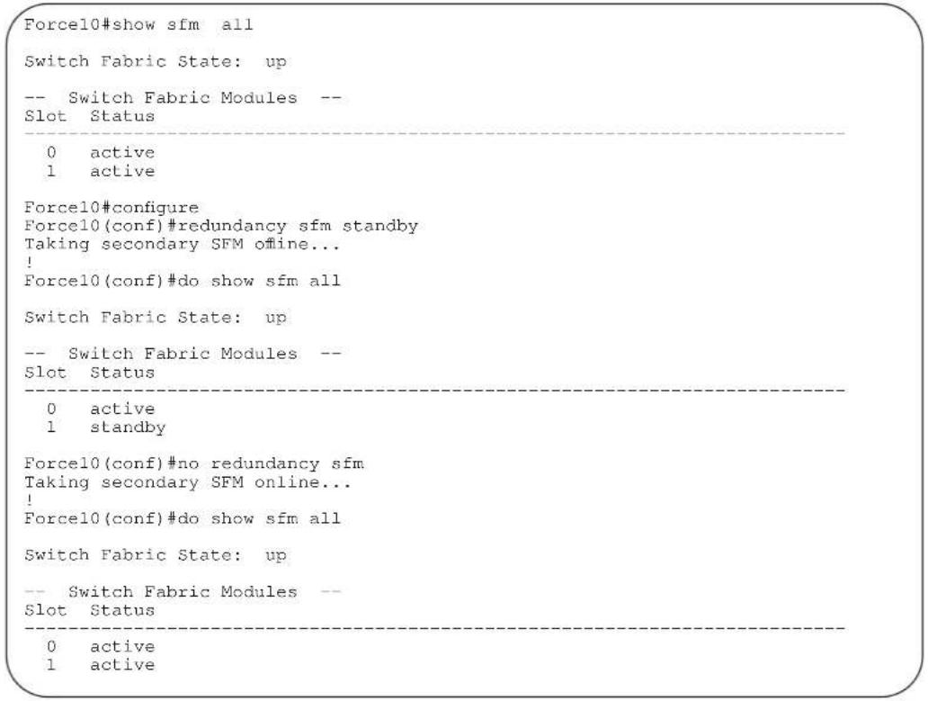
Related Commands
show sfm Display the SFM status
show switch links Display the switch fabric backplane or internal status.
redundancy synchronize

Manually synchronize data once between the Primary RPM and the Secondary RPM.
Syntax
redundancy synchronize [full | persistent-data | system-data]
Parameters
full Enter the keyword full to synchronize all data.
| persistent-data | Enter the keywords persistent-data to synchronize the startup configuration between RPMs. |
| system-data | Enter the keywords system-data to synchronize persistent-data and the running configuration file, event log, SFM and line card states. |
Defaults
Not configured.
Command Modes
EXEC Privilege
Command History
Version 8.1.1.0 Introduced on E-Series ExaScale
Version 7.5.1.0 Introduced on C-Series
Version 7.6.1.0 Introduced on E-Series
show patch

Display the system patches loaded with the In-Service Modular Hot Fix Command.
Syntax
show patch
Command Modes
EXEC
Command
History
Version 8.2.1.0 Introduced on E-Series
Related
Commands
patch flash://
RUNTIME_PATCH_DIR
Insert an In-Service Modular Hot-Fix patch.
show processes restartable

Display the processes and tasks configured for restartability.
Syntax
show processes restartable [history]
Parameters
history
Display the last time the restartable processes crashed.
Command Modes
EXEC Privilege
Command
History
Version 8.4.1.0 Introduced on E-Series
Example
Forcel0#sho processes restartable
| Process name restarted | State | How many times restarted | Timestamp last |
| radius | enabled | 0 | [-] |
| tacplus | enabled | 0 | [-] |
Force10#show processes restartable history
Process name
Timestamp last crashed
radius
[5/23/2001 10:11:47]
Related
Commands
process restartable
show redundancy

Display the current redundancy configuration.
Syntax
show redundancy
Command Modes
EXEC
EXEC Privilege
Command History
Version 8.1.1.0 Introduced on E-Series ExaScale
Version 7.5.1.0 Introduced on C-Series
Version 7.6.1.0 Introduced on E-Series
Example
Figure 22-4. show redundancy Command Example
| Forcel0#show redundancy | |
| -- RPM Status -- | |
| RPM Slot ID: 1 RPM Redundancy Role: Primary RPM State: Active RPM SW Version: 7.5.1.0 Link to Peer: Up | |
| -- PEER RPM Status -- | |
| RPM State: Standby RPM SW Version: 7.5.1.0 | |
| -- RPM Redundancy Configuration -- | |
| Primary RPM: rpm0 Auto Data Sync: Full Failover Type: Hot Failover Auto reboot RPM: Enabled Auto failover limit: 3 times in 60 minutes | |
| -- RPM Failover Record -- | |
| Failover Count: 1 Last failover timestamp: Jul 13 2007 21:25:32 Last failover Reason: User request | |
| -- Last Data Block Sync Record: -- | |
| Line Card Config: succeeded Jul 13 2007 21:28:53 Start-up Config: succeeded Jul 13 2007 21:28:53 SFM Config State: succeeded Jul 13 2007 21:28:53 Runtime Event Log: succeeded Jul 13 2007 21:28:53 Running Config: succeeded Jul 13 2007 21:28:53 Force10# |
Table 22-1. show redundancy Command Example Fields
| Field Description | |
| RPM Status Displays the following information:Slot number of the RPMWhether the RPM is Primary or StandbyThe state of the RPM: Active, Standby, Booting, or OfflineWhether the link to the second RPM is up or down. | |
| PEER RPM Status Displays the state of the second RPM, if present | |
| RPM RedundancyConfiguration | Displays the following information:which RPM is the preferred Primary on next boot (redundancy primary command)the data sync method configured (redundancy synchronize command).the failover type (you cannot change this; it is software dependent)Hot Failover means the running configuration and routing table are applied on secondary RPM. Fast Failover means the running configuration is not applied on the secondary RPM till failover occurs, and the routing table on line cards is cleared during failover.the status of auto booting the RPM (redundancy disable-auto-reboot command)the parameter for auto failover limit control (redundancy auto-failover-limit command) |
| RPM Failover Record Displays | the following information:RPM failover counter (to reset the counter, use the redundancy reset-counter command)the time and date of the last RPM failoverthe reason for the last RPM failover. |
| Last Data Sync Record Displays | the data sync information and the timestamp for the data sync:Start-up Config is the contents of the startup-config file.Line Card Config is the line card types configured and interfaces on those line cards.Runtime Event Log is the contents of the Event log.Running Config is the current running-config.This field only appears when you enter the command from the Primary RPM. |
Internet Group Management Protocol (IGMP)
Overview
The platforms on which a command is supported is indicated by the character — E for the E-Series, C for the C-Series, and S for the S-Series — that appears below each command heading.
This chapter contains the following sections:
- IGMP Commands
- IGMP Snooping Commands
IGMP Commands
FTOS supports IGMPv1/v2/v3 and is compliant with RFC-3376.
Important Points to Remember
- FTOS supports PIM-SM and PIM-SSM include and exclude modes.
- IGMPv2 is the default version of IGMP on interfaces. IGMPv3 can be configured on interfaces, and is backward compatible with IGMPv2.
- The maximum number of interfaces supported is 512 on the E-Series. On the C-Series and S-Series 31 interfaces are supported.
• Maximum number of groups supported – no hard limit - IGMPv3 router interoperability with IGMPv2 and IGMPv1 routers on the same subnet is not supported.
- An administrative command (ip igmp version) is added to manually set the IGMP version.
- All commands, previously used for IGMPv2, are compatible with IGMPv3.
The commands include:
- clear ip igmp groups
- debug ip igmp
- ip igmp access-group
- ip igmp group-join-limit
- ip igmp immediate-leave
- ip igmp last-member-query-interval
- ip igmp querier-timeout
- ip igmp query-interval
-
ip igmp query-max-resp-time
-
ip igmp ssm-map
- ip igmp static-group
- ip igmp version
• show ip igmp groups
• show ip igmp interface
• show ip igmp ssm-map
clear ip igmp groups

Clear entries from the group cache table.
Syntax
clear ip igmp groups [group-address | interface]
| Parameters | group-address | (OPTIONAL) Enter the IP multicast group address in dotted decimal format. |
| interface | (OPTIONAL) Enter the following keywords and slot/port or number information:For an 100/1000 Base-T Ethernet interface, enter the keyword gigabitethernet followed by the slot/port information.For a 1-Gigabit Ethernet interface, enter the keyword gigabitethernet followed by the slot/port information.For a SONET interface, enter the keyword sonet followed by the slot/port information.For a 10-Gigabit Ethernet interface, enter the keyword tengigabitethernet followed by the slot/port information. |
Command Modes
EXEC Privilege
Command History
| Version 7.6.1.0 Introduced on S-Series |
| Version 7.5.1.0 Introduced on C-Series |
| E-Series legacy command |
Usage Information
IGMP commands accept only non-VLAN interfaces—specifying VLAN will not yield a results.
debug ip igmp

Enable debugging of IGMP packets.
Syntax
debug ip igmp [group address | interface]
To disable IGMP debugging, enter no debug ip igmp [group address | interface]. To disable all debugging, enter undebug all.
| Parameters | group-address | (OPTIONAL) Enter the IP multicast group address in dotted decimal format. |
| interface | (OPTIONAL) Enter the following keywords and slot/port or number information:Enter one of the following keywords and slot/port or number information:For a 1-Gigabit Ethernet interface, enter the keyword GigabitEthernet followed by the slot/port information.For a Port Channel interface, enter the keyword port-channel followed by : number:C-Series and S-Series Range: 1-128E-Series Range: 1 to 32 for EtherScale, 1 to 255 for TeraScaleFor SONET interfaces, enter the keyword sonet followed by the slot/port information. This keyword is only available on E-Series and C-Series.For a 10-Gigabit Ethernet interface, enter the keywordTenGigabitEthernet followed by the slot/port information. |
| Defaults | Disabled |
| Command Modes | EXEC Privilege |
| Command History | Version 7.6.1.0 Introduced on S-Series |
| Version 7.5.1.0 Introduced on C-Series | |
| E-Series legacy command |
Usage IGMP commands accept only non-VLAN interfaces—specifying a VLAN will not yield results. This command displays packets for IGMP and IGMP Snooping.
ip igmp access-group

Use this feature to specify access control for packets.
Syntax
ip igmp access-group access-list
To remove the feature, use the no ip igmp access-group access-list command.
| Parameters | access-list | Enter the name of the extended ACL (16 characters maximum). |
| Defaults | Not configured | |
| mand Modes | INTERFACE (conf-if-interface-slot/port) | |
| Command History | Version 7.8.1.0 Introduced on C-Series and S-Series | |
| Version 7.6.1.0 Introduced on E-Series | ||
Usage The access list accepted is an extended ACL. This feature is used to block IGMP reports from hosts, on a per-interface basis; based on the group address and source address specified in the access list.
ip igmp group-join-limit

Use this feature to limit the number of IGMP groups that can be joined in a second.
Syntax
ip igmp group-join-limit number
| Parameters | number | Enter the number of IGMP groups permitted to join in a second. Range: 1 to 10000 |
| Defaults | No default values or behavior | |
| Command Modes | CONFIGURATION (conf-if-interface-slot/port) | |
| Command History | Version 7.8.1.0 Introduced on C-Series and S-Series | |
| Version 7.6.1.0 Introduced on E-Series | ||
ip igmp immediate-leave

Enable IGMP immediate leave.
Syntax
ip igmp immediate-leave [group-list prefix-list-name]
To disable ip igmp immediate leave, use the no ip igmp immediate-leave command.
| Parameters | group-list prefix-list-name | Enter the keyword group-list followed by a string up to 16 characters long of the prefix-list-name. |
| Defaults | Not configured | |
| Command Modes | INTERFACE | |
| Command History | Version 7.8.1.0 Introduced on S-Series | |
| Version 7.7.1.0 Introduced on C-Series | ||
| E-Series legacy command | ||
| Usage Information | Querier normally sends a certain number of group specific queries when a leave message is received, for a group, prior to deleting a group from the membership database. There may be situations in which immediate deletion of a group from the membership database is required. This command provides a way to achieve the immediate deletion. In addition, this command provides a way to enable immediate-leave processing for specified groups. | |
ip igmp last-member-query-interval

Change the last member query interval, which is the Max Response Time inserted into Group-Specific Queries sent in response to Leave Group messages. This interval is also the interval between Group-Specific Query messages.
Syntax ip igmp last-member-query-interval milliseconds
To return to the default value, enter no ip igmp last-member-query-interval.
| Parameters | milliseconds | Enter the number of milliseconds as the interval.Default: 1000 millisecondsRange: 100 to 65535 |
| Defaults | 1000 milliseconds | |
| Hand Modes | INTERFACE | |
| Command History | Version 7.8.1.0 Introduced on S-Series | |
| Version 7.7.1.0 Introduced on C-Series | ||
| E-Series legacy command | ||
ip igmp querier-timeout

Change the interval that must pass before a multicast router decides that there is no longer another multicast router that should be the querier.
Syntax ip igmp querier-timeout seconds
To return to the default value, enter no ip igmp querier-timeout.
| Parameters | seconds | Enter the number of seconds the router must wait to become the new querier.Default: 125 secondsRange: 60 to 300 |
| Defaults | 125 seconds | |
| mand Modes | INTERFACE | |
| Command History | Version 7.8.1.0 Introduced on S-Series | |
| Version 7.7.1.0 Introduced on C-Series | ||
| Version 7.6.1.0 Introduced on S-Series in Interface VLAN mode only to enable that system to act as an IGMP Proxy Querier. | ||
| Version 7.5.1.0 Introduced on C-Series in Interface VLAN mode only to enable that system to act as an IGMP Proxy Querier. | ||
| E-Series legacy command | ||
ip igmp query-interval

Change the transmission frequency of IGMP general queries sent by the Querier.
Syntax
ip igmp query-interval seconds
To return to the default values, enter no ip igmp query-interval.
Parameters
| seconds | Enter the number of seconds between queries sent out.Default: 60 secondsRange: 1 to 18000 |
| 60 seconds | |
| INTERFACE | |
| Version 7.8.1.0 Introduced on S-Series | |
| Version 7.7.1.0 Introduced on C-Series | |
| Version 7.6.1.0 Introduced on S-Series in Interface VLAN mode only to enable that system to act as an IGMP Proxy Querier. | |
| Version 7.5.1.0 Introduced on C-Series in Interface VLAN mode only to enable that system to act as an IGMP Proxy Querier. | |
| E-Series legacy command | |
ip igmp query-max-resp-time

Set the maximum query response time advertised in general queries.
Syntax
ip igmp query-max-resp-time seconds
To return to the default values, enter no ip igmp query-max-resp-time.
Parameters
| seconds | Enter the number of seconds for the maximum response time.Default: 10 secondsRange: 1 to 25 |
| 10 seconds | |
| INTERFACE | |
| Version 7.8.1.0 Introduced on S-Series | |
| Version 7.7.1.0 Introduced on C-Series | |
| Version 7.6.1.0 Introduced on S-Series in Interface VLAN mode only to enable that system to act as an IGMP Proxy Querier. | |
| Version 7.5.1.0 Introduced on C-Series in Interface VLAN mode only to enable that system to act as an IGMP Proxy Querier. | |
| E-Series legacy command | |
Command Modes
Command History
ip igmp ssm-map

Use a statically configured list to translate (*,G) memberships to (S,G) memberships.
Syntax
ip igmp ssm-map std-access-list source-address
Undo this configuration, that is, remove SSM map (S,G) states and replace them with (*,G) states using the command ip igmp ssm-map std-access-list source-address command.
Parameters
| std-access-list | Specify the standard IP access list that contains the mapping rules for multicast groups. |
| source-address | Specify the multicast source address to which the groups are mapped. |
Command Modes
CONFIGURATION
Command History
Version 7.8.1.0 Introduced on C-Series and S-Series
Version 7.7.1.0 Introduced on E-Series
Usage Information
Mapping applies to both v1 and v2 IGMP joins; any updates to the ACL are reflected in the IGMP groups. You may not use extended access lists with this command. When a static SSM map is configured and the router cannot find any matching access lists, the router continues to accept (^*,G) groups.
Related Commands
ip access-list standard Create a standard access list to filter based on IP address.
ip igmp static-group

Configure an IGMP static group.
Syntax
ip igmp static-group {group address [exclude [source address]] | [include {source address}]}
To delete a static address, use the no ip igmp static-group {group address [exclude [source address]] | [include {source address}]} command.
Parameters
| group address | Enter the group address in dotted decimal format (A.B.C.D) |
| exclude source address | (OPTIONAL) Enter the keyword exclude followed by the source address, in dotted decimal format (A.B.C.D), for which a static entry needs to be added. |
| include source address | (OPTIONAL) Enter the keyword include followed by the source address, in dotted decimal format (A.B.C.D), for which a static entry needs to be added.Note: A group in include mode must have at least one source address defined. |
Defaults
No default values or behavior
Command Modes
INTERFACE
Command History
Version 7.8.1.0 Introduced on S-Series
Version 7.7.1.0 Introduced on C-Series
| Version 7.5.1.0 Expanded to support the exclude and include options | |
| E-Series legacy command | |
| Usage Information | A group in the include mode should have at least one source address defined. In exclude mode if no source address is specified, FTOS implicitly assumes all sources are included. If neither include or exclude is specified, FTOS implicitly assumes a IGMPv2 static join. |
| Command LimitationsOnly one mode (include or exclude) is permitted per multicast group per interface. To configure another mode, all sources belonging to the original mode must be unconfigured.If a static configuration is present and a packet for the same group arrives on an interface, the dynamic entry will completely overwrite all the static configuration for the group. | |
| Related Commands | show ip igmp groups Display IGMP group information |
ip igmp version

Manually set the version of the router to IGMPv2 or IGMPv3.
Syntax
ip igmp version {2 | 3}
Parameters
2 Enter the number 2 to set the IGMP version number to IGMPv2.
3 Enter the number 3 to set the IGMP version number to IGMPv3.
Defaults
2 (that is IGMPv2)
Command Modes
INTERFACE
Command History
Version 7.8.1.0 Introduced on S-Series
Version 7.7.1.0 Introduced on C-Series
Version 7.5.1.0 Introduced for E-Series
show ip igmp groups

View the IGMP groups.
Syntax
show ip igmp groups [group-address [detail] | detail | interface [group-address [detail]]]
Parameters
| group-address | (OPTIONAL) Enter the group address in dotted decimal format to view information on that group only. |
| interface | (OPTIONAL) Enter the interface type and slot/port information:For a 100/1000 Ethernet interface, enter the keyword gigabitethernet followed by the slot/port information.For a 1-Gigabit Ethernet interface, enter the keyword gigabitethernet followed by the slot/port information.For a Port Channel interface, enter the keyword port-channel followed by a number:C-Series and S-Series Range: 1-128E-Series Range: 1 to 32 for EtherScale, 1 to 255 for TeraScale and 1 to 512 for ExaScale.For a Loopback interface, enter the keyword loopback followed by a number from 0 to 16383.For a SONET interface, enter the keyword sonet followed by the slot/port information.For a 10-Gigabit Ethernet interface, enter the keyword tengigabitethernet followed by the slot/port information.For a VLAN interface enter the keyword vlan followed by a number from 1 to 4094. |
| detail | (OPTIONAL) Enter the keyword detail to display the IGMPv3 source information. |
Command Modes
EXEC
EXEC Privilege
Command History
| Version 7.6.1.0 Introduced on S-Series and on C-Series | |
| Version 7.5.1.0 | Expanded to support the detail option. |
| E-Series legacy command | |
Usage Information
This command displays the IGMP database including configured entries for either all groups on all interfaces, or all groups on specific interfaces, or specific groups on specific interfaces.
Example
Figure 23-1. show ip igmp groups Command Example
| Force10#show ip igmp groups | ||||
| IGMP Connected Group Membership | ||||
| Group Address | Interface | Uptime | Expires | Last Reporter |
| 224.0.1.40 | GigabitEthernet 13/6 | 09:45:23 | 00:02:08 | 10.87.7.5 |
| Force10# | ||||
Table 23-1. show ip igmp groups Command Example Fields
| Field Description | |
| Group Address Lists the multicast address for the IGMP group. | |
| Interface Lists the interface type, slot and port number. | |
| Uptime Displays the amount of time the group has been operational. | |
| Expires Displays the amount of time until the entry expires. | |
| Last Reporter Displays the IP address of the last host to be a member of the IGMP group. | |
show ip igmp interface

View information on the interfaces participating in IGMP.
Syntax
show ip igmp interface [interface]
Parameters
| interface | (OPTIONAL) Enter the interface type and slot/port information:For a 100/1000 Ethernet interface, enter the keyword gigabitethernet followed by the slot/port information.For a 1-Gigabit Ethernet interface, enter the keyword gigabitethernet followed by the slot/port information.For a Port Channel interface, enter the keyword port-channel followed by a number:C-Series and S-Series Range: 1-128E-Series Range: 1 to 32 for EtherScale, 1 to 255 for TeraScale and 1 to 512 for ExaScale.For a Loopback interface, enter the keyword loopback followed by a number from 0 to 16383.For a SONET interface, enter the keyword sonet followed by the slot/port information.For a 10-Gigabit Ethernet interface, enter the keyword tengigabitethernet followed by the slot/port information.For a VLAN interface enter the keyword vlan followed by a number from 1 to 4094. |
Command Modes
EXEC
EXEC Privilege
Command History
| Version 7.6.1.0 Introduced on S-Series |
| Version 7.5.1.0 Introduced on C-Series |
| E-Series legacy command |
Usage Information
IGMP commands accept only non-VLAN interfaces—specifying VLAN will not yield a results.
Example
Figure 23-2. show ip igmp interface Command Example
| Forcel0#show ip igmp interface |
| GigabitEthernet 0/0 is down, line protocol is down |
| Internet protocol processing disabled |
| GigabitEthernet 0/5 is down, line protocol is down |
| Internet protocol processing disabled |
| GigabitEthernet 0/6 is down, line protocol is down |
| Internet protocol processing disabled |
| GigabitEthernet 0/7 is up, line protocol is down |
| Internet protocol processing disabled |
| GigabitEthernet 7/9 is up, line protocol is up |
| Internet address is 10.87.5.250/24 |
| IGMP is enabled on interface |
| IGMP query interval is 60 seconds |
| IGMP querier timeout is 120 seconds |
| IGMP max query response time is 10 seconds |
| IGMP last member query response interval is 1000 ms |
| IGMP activity: 0 joins, 0 leaves |
| IGMP querying router is 10.87.5.250 (this system) |
| IGMP version is 2 |
show ip igmp ssm-map

Display is a list of groups that are currently in the IGMP group table and contain SSM mapped sources.
Syntax
show ip igmp ssm-map [group]
| Parameters | group | (OPTIONAL) Enter the multicast group address in the form A.B.C.D to display the list of sources to which this group is mapped. |
| Command Modes | EXEC | |
| EXEC Privilege | ||
| Command History | Version 7.8.1.0 Introduced on C-Series and S-Series | |
| Version 7.7.1.0 Introduced on E-Series | ||
| Related Commands | ip igmp | Use a statically configured list to translate (*,G) memberships to (S,G) memberships. |
| ssm-map | ||
IGMP Snooping Commands
FTOS supports IGMP Snooping version 2 and 3 on all Dell Force10 systems:
- ip igmp snooping enable
- ip igmp snooping fast-leave
- ip igmp snooping flood
- ip igmp snooping last-member-query-interval
- ip igmp snooping mrouter
- ip igmp snooping querier
• show ip igmp snooping mrouter
Important Points to Remember for IGMP Snooping
- FTOS supports version 1, version 2, and version 3 hosts.
- FTOS IGMP snooping implementation is based on IP multicast address (not based on Layer 2 multicast mac-address) and the IGMP snooping entries are in Layer 3 flow table not in Layer 2 FIB.
- FTOS IGMP snooping implementation is based on draft-ietf-magma-snoop-10.
- FTOS supports IGMP snooping on JUMBO enabled cards.
- IGMP snooping is not enabled by default on the switch.
- A maximum of 1800 groups and 600 VLAN are supported.
- IGMP snooping is not supported on default VLAN interface.
- IGMP snooping is not supported over VLAN-Stack-enabled VLAN interfaces (you must disable IGMP snooping on a VLAN interface before configuring VLAN-Stack-related commands).
- IGMP snooping does not react to Layer 2 topology changes triggered by STP.
- IGMP snooping reacts to Layer 2 topology changes triggered by MSTP by sending a general query on the interface that comes in FWD state.
Important Points to Remember for IGMP Querier
• The IGMP snooping Querier supports version 2.
- You must configure an IP address to the VLAN interface for IGMP snooping Querier to begin. The IGMP snooping Querier disables itself when a VLAN IP address is cleared, and then it restarts itself when an IP address is re-assigned to the VLAN interface.
- When enabled, IGMP snooping Querier will not start if there is a statically configured multicast router interface in the VLAN.
- When enabled, IGMP snooping Querier starts after one query interval in case no IGMP general query (with IP SA lower than its VLAN IP address) is received on any of its VLAN members.
- When enabled, IGMP snooping Querier periodically sends general queries with an IP source address of the VLAN interface. If it receives a general query on any of its VLAN member, it will check the IP source address of the incoming frame.
If the IP SA in the incoming IGMP general query frame is lower than the IP address of the VLAN interface, then the switch disables its IGMP snooping Querier functionality.
If the IP SA of the incoming IGMP general query is higher than the VLAN IP address, the switch will continue to work as an IGMP snooping Querier.
ip igmp snooping enable

Enable IGMP snooping on all or a single VLAN. This is the master on/off switch to enable IGMP snooping.
Syntax
ip igmp snooping enable
To disable IGMP snooping, enter no ip igmp snooping enable command.
Defaults
Disabled
Command Modes
CONFIGURATION
INTERFACE VLAN
Command History
Version 7.6.1.0 Introduced on S-Series
Version 7.5.1.0 Introduced on C-Series
E-Series legacy command
Usage Information
You must enter this command to enable IGMP snooping. When enabled from CONFIGURATION mode, IGMP snooping is enabled on all VLAN interfaces (except default VLAN).

Note: You must execute the no shutdown command on the VLAN interface for IGMP Snooping to function.
Related Commands
no shutdown Activate an interface
ip igmp snooping fast-leave

Enable IGMP snooping fast leave for this VLAN.
Syntax ip igmp snooping fast-leave
To disable IGMP snooping fast leave, use the no igmp snooping fast-leave command.
Defaults Not configured
Command Modes INTERFACE VLAN—(conf-if-vl-n)
Command History
Version 7.6.1.0 Introduced on S-Series
Version 7.5.1.0 Introduced on C-Series
E-Series legacy command
Usage Information Queriers normally send a certain number of queries when a leave message is received prior to deleting a group from the membership database. There may be situations in which fast deletion of a group is required. When IGMP fast leave processing is enabled, the switch will remove an interface from the multicast group as soon as it detects an IGMP version 2 leave message on the interface.
ip igmp snooping flood

This command controls the flooding behavior of unregistered multicast data packets. On the E-Series, when flooding is enabled (the default), unregistered multicast data traffic is flooded to all ports in a VLAN. When flooding is disabled, unregistered multicast data traffic is forwarded to only multicast router ports, both static and dynamic, in a VLAN. If there is no multicast router port in a VLAN, then unregistered multicast data traffic is dropped. On the
C-Series and S-Series, unregistered multicast data traffic is dropped when flooding is disabled; they do not forward the packets to multicast router ports. On the C-Series and S-Series, Layer 3 multicast must be disabled (no ip multicast-routing) in order to disable Layer 2 multicast flooding.
Syntax ip igmp snooping flood
Defaults Enabled
Command Modes CONFIGURATION
Command History
Version 8.2.1.0 Introduced on the C-Series and S-Series.
Version 7.7.1.1 Introduced on E-Series.
ip igmp snooping last-member-query-interval

The last member query interval is the “maximum response time” inserted into Group-Specific queries sent in response to Group-Leave messages. This interval is also the interval between successive Group-Specific Query messages. Use this command to change the last member query interval.
Syntax
ip igmp snooping last-member-query-interval milliseconds
To return to the default value, enter no ip igmp snooping last-member-query-interval.
| Parameters | milliseconds | Enter the interval in milliseconds.Default: 1000 millisecondsRange: 100 to 65535 |
| Defaults | 1000 milliseconds | |
| Command Modes | INTERFACE VLAN | |
| Command History | Version 7.6.1.0 Introduced on S-Series | |
| Version 7.5.1.0 Introduced on C-Series | ||
| E-Series legacy command | ||
ip igmp snooping mrouter

Statically configure a VLAN member port as a multicast router interface.
Syntax
ip igmp snooping mrouter interface interface
To delete a specific multicast router interface, use the no igmp snooping mrouter interface interface command.
| Parameters | interfaceinterface | Enter the following keywords and slot/port or number information:For an 100/1000 Ethernet interface, enter the keyword followed by the slot/port information.FigabitEthernetGigabitEthernetfor a 1-Gigabit Ethernet interface, enter the keyword followed by the slot/port information.For a 10-Gigabit Ethernet interface, enter the keyword followed by the slot/port information.For a Port Channel interface, enter the keyword port-channel followed by a number:C-Series and S-Series Range: 1-128E-Series Range: 1 to 32 for EtherScale, 1 to 255 for TeraScale and 1 to 512 for ExaScale. |
| Defaults | Not configured | |
| Command Modes | INTERFACE VLAN—(conf-if-vl-n) | |
| Command History | Version 7.6.1.0 Introduced on S-Series | |
| Version 7.5.1.0 Introduced on C-Series | ||
| E-Series legacy command | ||
Usage Information
FTOS provides the capability of statically configuring interface to which a multicast router is attached. To configure a static connection to the multicast router, enter the ip igmp snooping mrouter interface command in the VLAN context. The interface to the router must be a part of the VLAN where you are entering the command.
ip igmp snooping querier

Enable IGMP querier processing for the VLAN interface.
Syntax
ip igmp snooping querier
To disable IGMP querier processing for the VLAN interface, enter no ip igmp snooping querier command.
Defaults
Not configured
Command Modes
INTERFACE VLAN—(conf-if-vl-n)
Command History
Version 7.6.1.0 Introduced on S-Series
Version 7.5.1.0 Introduced on C-Series
E-Series legacy command
Usage Information
This command enables the IGMP switch to send General Queries periodically. This is useful when there is no multicast router present in the VLAN because the multicast traffic does not need to be routed. An IP address must be assigned to the VLAN interface for the switch to act as a querier for this VLAN.
show ip igmp snooping mrouter

Display multicast router interfaces.
Syntax
show ip igmp snooping mrouter [vlan number]
Parameters
vlan number
Enter the keyword vlan followed by the vlan number.
Range: 1-4094
Command Modes
EXEC
EXEC Privilege
Command History
Version 7.6.1.0 Introduced on S-Series
Version 7.5.1.0 Introduced on C-Series
E-Series legacy command
Example
Figure 23-3. show ip igmp snooping mrouter Command Example
Force10#show ip igmp snooping mrouter
Interface Router Ports
Vlan 2 Gi 13/3, Po 1
Force10#
Related Commands
show ip igmp groups Use this IGMP command to view groups
Interfaces
Overview
This chapter defines interface commands and is divided into the following sections:
- Basic Interface Commands
• Port Channel Commands
• Time Domain Reflectometer (TDR) - UDP Broadcast
The symbols C E S under command headings indicate which Dell Force10 platforms — C-Series, E-Series, or S-Series, respectively — support the command.
Although all interfaces are supported on E-Series ExaScale, some interface functionality is supported on E-Series ExaScale ex with FTOS 8.2.1.0. and later. When this is the case that is noted in the command history.
Basic Interface Commands
The following commands are for physical, Loopback, and Null interfaces:
- clear counters
- clear dampening
- cx4-cable-length
- dampening
- description
- disable-on-sfm-failure
- duplex (Management)
- duplex (10/100 Interfaces)
- flowcontrol
- interface
- interface loopback
• interface ManagementEthernet - interface null
- interface range
• interface range macro (define)
• interface range macro name - interface vlan
-
ipg (Gigabit Ethernet interfaces)
-
ipg (10 Gigabit Ethernet interfaces)
- keepalive
- lfs enable (EtherScale)
- link debounce-timer
- monitor
• mtu - negotiation auto
- portmode hybrid
- rate-interval
• show config
• show config (from INTERFACE RANGE mode)
• show interfaces
• show interfaces configured
• show interfaces dampening
• show interfaces description
• show interfaces linecard
• show interfaces phy
• show interfaces stack-unit
• show interfaces status
• show interfaces switchport
• show interfaces transceiver
• show range - shutdown
• speed (for 10/100/1000 interfaces)
• speed (Management interface) - switchport
- wanport
clear counters

Clear the counters used in the show interfaces commands for all VRRP groups, VLANs, and physical interfaces, or selected ones.
Syntax
clear counters [interface] [vrrp [{ipv6] vrid | vrf instance}] | learning-limit]
Parameters
| interface | (OPTIONAL) Enter any of the following keywords and slot/port or number to clear counters from a specified interface:For a 1-Gigabit Ethernet interface, enter the keywordGigabitEthernet followed by the slot/port information.For a Loopback interface, enter the keywordloopbackfollowed by a number from 0 to 16383.For a Port Channel interface, enter the keywordport-channelfollowed by a number:C-Series and S-Series Range: 1-128E-Series Range: 1 to 32 for EtherScale, 1 to 255 for TeraScale and 1 to 512 for ExaScale.For the management interface on the RPM, enter the keywordManagementEthernetfollowed by slot/port information. The slot range is 0-1, and the port range is 0.For a SONET interface, enter the keywordsonetfollowed by the slot/port information.For a 10-Gigabit Ethernet interface, enter the keywordTenGigabitEthernet followed by the slot/port information.For a VLAN, enter the keywordvlanfollowed by a number from 1 to 4094. |
| vrrp[[ipv6] vrid] | (OPTIONAL) Enter the keywordvrrpto clear the counters of all VRRP groups. To clear the counters of VRRP groups on all IPv6 interfaces, enter ipv6. To clear the counters of a specified group, enter avridnumber from 1 to 255. |
| vrrp[vrf instance] | (OPTIONAL) E-Series only: Enter the keywordvrrpto clear counters for all VRRP groups. To clear the counters of VRRP groups in a specified VRF instance, enter the name of the instance (32 characters maximum). IPv6 VRRP groups are not supported. |
| learning-limit | (OPTIONAL) Enter the keywordlearning-limitto clear unknown source address (SA) drop counters when MAC learning limit is configured on the interface.Note: This option is not supported on the S-Series, as the MAC learning limit is not supported |
Defaults
Without an interface specified, the command clears all interface counters.
Command Modes
EXEC Privilege
Command History
| Version 8.4.1.0 On the E-Series, support was added for VRRP groups in a VRF instance. |
| Version 8.2.1.0 Support for 4093 VLANs on E-Series ExaScale. Prior to release supported 2094. |
| Version 8.1.1.0 Introduced on E-Series ExaScale |
| Version 7.6.1.0 Introduced on S-Series |
| Version 7.5.1.0 Introduced on C-Series |
| Version 6.5.1.0 Updated definition of the learning-limit option for clarity. |
Example
Figure 24-1. clear counters Command Example
| Force10#clear counters |
| Clear counters on all interfaces [confirm] |
Related Commands
| mac learning-limit Allow aging of MACs even though a learning-limit is configured or disallow station move on learnt MACs. |
| show interfaces Displays information on the interfaces. |
clear dampening
C E S
Clear the dampening counters on all the interfaces or just the specified interface.
Syntax
clear dampening [interface]
Parameters
interface
(Optional) Enter one of the following keywords and slot/port or number information:
- For a 1-Gigabit Ethernet interface, enter the keyword GigabitEthernet followed by the slot/port information.
- For a Port Channel interface, enter the keyword followed by a number: port-channel
C-Series and S-Series Range: 1-128
E-Series Range: 1 to 32 for EtherScale, 1 to 255 for TeraScale and 1 to 512 for ExaScale.
- For a SONET interface, enter the keyword sonet followed by the slot/port information.
- For a 10-Gigabit Ethernet interface, enter the keyword TenGigabitEthernet followed by the slot/port information.
Defaults
Without a specific interface specified, the command clears all interface dampening counters
Command Modes
EXEC Privilege
Command History
Version 8.1.1.0 Introduced on E-Series ExaScale
Version 7.6.1.0 Introduced on S-Series
Version 7.5.1.0 Introduced on C-Series
Version 7.4.1.0 Introduced on E-Series
Example
Force10#clear dampening gigabitethernet 1/2 Clear dampening counters on Gi 1/2 [confirm] y Force10#
Related Commands
show interfaces dampening
Display interface dampening information.
dampening Configure dampening on an interface.
cx4-cable-length
S
Configure the length of the cable to be connected to the selected CX4 port.
Syntax
[no] cx4-cable-length {long | medium | short}
Parameters
long | medium | short
Enter the keyword that matches the cable length to be used at the selected port:
short = For 1-meter and 3-meter cable lengths
medium = For 5-meter cable length
long = For 10-meter and 15-meter cable lengths
Defaults medium
Mode Interface
Command History
Version 7.7.1.0 Introduced on S-Series
Usage Information
This command only works on ports that the system recognizes as CX4 ports. The figure below shows an attempt to configure an XFP port in an S25P with the command after inserting a CX4 converter into the port:

Note: When using a long CX4 cable between the C-Series and the S-Series, configure the cable using the cx4-cable-length short command only to avoid any errors.
Note: 15M CX4 active cable is not supported on C-Series and S-series. It is only supported for S2410 with active end on the device.
Example
Figure 24-2. Example of Unsuccessful CX4 Cable Length Configuration
Force10#show interfaces tengigabitethernet 0/26 | grep "XFP type"
Pluggable media present, XFP type is 10GBASE-CX4
Force10(conf-if-te-0/26)#cx4-cable-length short
% Error: Unsupported command.
Force10(conf-if-te-0/26)#cx4-cable-length medium
% Error: Unsupported command.
Force10(conf-if-te-0/26)#cx4-cable-length long
% Error: Unsupported command.
Force10(conf-if-te-0/26)#
The figure below shows a successful CX4 cable length configuration.
Example
Figure 24-3. Example of CX4 Cable Length Configuration
Force10#config
Force10(config)#interface tengigabitethernet 0/52
Force10(conf-if-0/52)#cx4-cable-length long
Force10(conf-if-0/52)#show config
!
interface TenGigabitEthernet 0/51
no ip address
cx4-cable-length long
shutdown
Force10(conf-if-0/52)#exit
Force10(config)#
For details on using XFP ports with CX4 cables, see your S-Series hardware guide.
Related Commands
show config Display the configuration of the selected interface.
dampening

Configure dampening on an interface.
Syntax
dampening [[[half-life] [reuse-threshold]] [suppress-threshold]] [max-suppress-time]]
To disable dampening, use the no dampening [[[half-life] [reuse-threshold]] [suppress-threshold]] [max-suppress-time]] command syntax.
Parameters
| half-life | Enter the number of seconds after which the penalty is decreased. The penalty is decreased by half after the half-life period expires. Range: 1 to 30 seconds Default: 5 seconds |
| reuse-threshold | Enter a number as the reuse threshold, the penalty value below which the interface state is changed to “up”. Range: 1 to 20000 Default: 750 |
| suppress-threshold | Enter a number as the suppress threshold, the penalty value above which the interface state is changed to “error disabled”. Range: 1 to 20000 Default: 2500 |
| max-suppress-time | Enter the maximum number for which a route can be suppressed. The default is four times the half-life value. Range: 1 to 86400 Default: 20 seconds |
Defaults
Disabled
Command Modes
INTERFACE (conf-if-)
Command History
Version 8.1.1.0 Introduced on E-Series ExaScale
Version 7.6.1.0 Introduced on S-Series
Version 7.5.1.0 Introduced on C-Series
Version 7.4.1.0 Introduced on E-Series
Example
Force10(conf-if-gi-3/2)#dampening 20 800 4500 120 Force10(conf-if-gi-3/2)#
Usage Information
With each flap, FTOS penalizes the interface by assigning a penalty (1024) that decays exponentially depending on the configured half-life. Once the accumulated penalty exceeds the suppress threshold value, the interface is moved to the error-disabled state. This interface state is deemed as “down” by all static/dynamic Layer 2 and Layer 3 protocols. The penalty is exponentially decayed based on the half-life timer. Once the penalty decays below the reuse threshold, the interface is enabled. The configured parameters should follow:
• suppress-threshold should be greater than reuse-threshold
- max-suppress-time should be at least 4 times half-life

Note: Dampening cannot be applied on an interface that is monitoring traffic for other interfaces.
Related Commands
clear dampening Clear the dampening counters on all the interfaces or just the specified interface.
show interfaces dampening Display interface dampening information.
description
| Syntax | description desc_textTo delete a description, enter no description. | |
| Parameters | desc_text | Enter a text string up to 240 characters long. |
| Defaults | No description is defined. | |
| Command Modes | INTERFACE | |
| Command History | Version 8.1.1.0 Introduced on E-Series ExaScale | |
| Version 7.6.1.0 Introduced on S-Series | ||
| Version 7.5.1.0 Introduced on C-Series | ||
| Version 7.4.1.0 Modified for E-Series: Revised from 78 to 240 characters. | ||
| Usage Information | Spaces between characters are not preserved after entering this command unless you enclose the entire description in quotation marks ("desc_text").Entering a text string after the description command overwrites any previous text string configured as the description.The shutdown and description commands are the only commands that you can configure on an interface that is a member of a port-channel.Use the show interfaces description command to display descriptions configured for each interface. | |
| Related Commands | show interfaces description | Display description field of interfaces. |
disable-on-sfm-failure
| E | Disable select ports on E300 systems when a single SFM is available. |
| Syntax | disable-on-sfm-failureTo delete a description, enter no disable-on-sfm-failure. |
| Defaults | Port is not disabled |
| Command Modes | INTERFACE |
| Command History | Version 7.7.1.0 Introduced on E300 systems only |
| Usage Information | When an E300 system boots up and a single SFM is active this configuration, any ports configured with this feature will be shut down. If an SFM fails (or is removed) in an E300 system with two SFM, ports configured with this feature will be shut down. All other ports are treated normally.When a second SFM is installed or replaced, all ports are booted up and treated as normally. This feature does not take affect until a single SFM is active in the E300 system. |
duplex (Management)
| Syntax | duplex {half | full} | |
| To return to the default setting, enter no duplex. | ||
| Parameters | half Enter the keyword half to set the Management interface to transmit only in one direction. | |
| full Enter the keyword full to set the Management interface to transmit in both directions. | ||
| Defaults | Not configured | |
| Command Modes | INTERFACE | |
| Command History | Version 8.1.1.0 Introduced on E-Series ExaScale | |
| Version 7.5.1.0 Introduced on C-Series | ||
| Version 6.4.1.0 Documentation modified—added Management to distinguish from duplex (10/100 Interfaces) | ||
| Usage Information | This command applies only to the Management interface on the RPMs. | |
| Related Commands | interface ManagementEthernet | Configure the Management port on the system (either the Primary or Standby RPM). |
| duplex (Management) | Set the mode of the Management interface. | |
| management route Configure a static route that points to the Management interface or a forwarding router. | ||
| speed (Management interface) | Set the speed on the Management interface. | |
duplex (10/100 Interfaces)
| C E S | Configure duplex mode on any physical interfaces where the speed is set to 10/100.Syntax duplex {half | full}To return to the default setting, enter no duplex. | |
| Parameters | half | Enter the keyword half to set the physical interface to transmit only in one direction. |
| full | Enter the keyword full to set the physical interface to transmit in both directions. | |
| Defaults | Not configured | |
| Command Modes | INTERFACE | |
| Command History | Version 8.1.1.0 Introduced on E-Series ExaScale | |
| Version 7.6.1.0 Introduced on S-Series | ||
| Version 7.5.1.0 Introduced on C-Series | ||
| Version 6.4.1.0 Introduced | ||
Usage Information
This command applies to any physical interface with speed set to 10/100.

Note: Starting with FTOS 7.8.1.0, when a copper SFP2 module with catalog number GP-SFP2-1T is used in the S25P model of the S-Series, its speed can be manually set with the speed command. When the speed is set to 10 or 100 Mbps, the duplex command can also be executed.
Related Commands
speed (for 10/100/1000 interfaces) Set the speed on the Base-T Ethernet interface.
negotiation auto Enable or disable auto-negotiation on an interface.
flowcontrol

Control how the system responds to and generates 802.3x pause frames on 1Gig and 10Gig line cards.
Syntax
flowcontrol rx {off | on} tx {off | on} threshold {<1-2047><1-2013><1-2013>}
The threshold keyword is supported on C-Series and S-Series only.
Parameters
| rx on | Enter the keywords rx on to process the received flow control frames on this port. This is the default value for the receive side. |
| rx off | Enter the keywords rx off to ignore the received flow control frames on this port. |
| tx on | Enter the keywords tx on to send control frames from this port to the connected device when a higher rate of traffic is received. This is the default value on the send side. |
| tx off | Enter the keywords tx off so that flow control frames are not sent from this port to the connected device when a higher rate of traffic is received. |
| threshold(C-Series and S-Series only) | When tx on is configured, you can set the threshold values for:Number of flow-control packet pointers: 1-2047 (default = 75)Flow-control buffer threshold in KB: 1-2013 (default = 49KB)Flow-control discard threshold in KB: 1-2013 (default= 75KB) |
Defaults
C-Series: rx off tx off
E-Series: rx on tx on
S-Series: rx off tx off
Command Modes
INTERFACE
Command History
Version 8.1.1.0 Introduced on E-Series ExaScale
Version 6.5.1.9 and 7.4.1.0 Introduced on E-Series
Version 7.8.1.0 Introduced on C-Series and S-Series with thresholds
Usage Information
The globally assigned 48-bit Multicast address 01-80-C2-00-00-01 is used to send and receive pause frames. To allow full duplex flow control, stations implementing the pause operation instruct the MAC to enable reception of frames with a destination address equal to this multicast address.
The pause:
- Starts when either the packet pointer or the buffer threshold is met (whichever is met first). When the discard threshold is met, packets are dropped.
- Ends when both the packet pointer and the buffer threshold fall below 50% of the threshold settings.
The discard threshold defines when the interface starts dropping the packet on the interface. This may be necessary when a connected device does not honor the flow control frame sent by the S-Series. The discard threshold should be larger than the buffer threshold so that the buffer holds at least hold at least 3 packets.
On 4-port 10G line cards: Changes in the flow-control values are not reflected automatically in the show interface output for 10G interfaces. This issue results from the fact that 10G interfaces do not support auto-negotiation per-se. On 1G interfaces, changing the flow control values causes an automatic interface flap, after which PAUSE values are exchanged as part of the auto-negotiation process. As a workaround, apply the new settings, execute shut followed by no shut on the interface, and then check the running-config of the port.
Important Points to Remember
- Do not enable tx pause when buffer carving is enabled. Consult Dell Force10 TAC for information and assistance.
- Asymmetric flow control (rx on tx off or rx off tx on) setting for the interface port less than 100 Mb/s speed is not permitted. The following error is returned:
Can't configure Asymmetric flowcontrol when speed <1G, config ignored
- The only configuration applicable to half duplex ports is rx off tx off. The following error is returned:
Can't configure flowcontrol when half duplex is configure, config ignored
- Half duplex cannot be configured when the flow control configuration is on (default is rx on tx on). The following error is returned:
Can't configure half duplex when flowcontrol is on, config ignored
Note: The flow control must be off (rx off tx off) before configuring the half duplex.
- Speeds less than 1 Gig cannot be configured when the asymmetric flow control configuration is on. The following error is returned:
Can't configure speed <1G when Asymmetric flowcontrol is on, config ignored
• FTOS only supports rx on tx on and rx off tx off for speeds less than 1 Gig (Symmetric).
- On the C-Series and S-Series systems, the flow-control sender and receiver must be on the same port-pipe. Flow control is not supported across different port-pipes on the C-Series or S-Series system.
Example
Figure 24-4. show running config (partial)
Force10(conf-if-gi-0/1)#show config
!
interface GigabitEthernet 0/1
no ip address
switchport
no negotiation auto
flowcontrol rx off tx on
no shutdown
...
The table below displays how FTOS negotiates the flow control values between two Dell Force10 chassis connected back-to-back using 1G copper ports.
Table 24-1. Negotiated Flow Control Values
| Configured Negotiated | |||||||
| LocRxConf Loc | TxConf Remo | eRxConf RemoteTx | Conf LocNegRx | LocNegTx Rem | NegRx RemNegTx | ||
| off off off | off | off | off | off | off | off | |
| off | on | off | off | off | off | ||
| on | off | off | off | off | off | ||
| on | on | off | off | off | off | ||
| off on off | off | off | off | off | off | off | |
| off | on | off | off | off | off | ||
| on | off | off | on | on | off | ||
| on | on | off | off | off | off | ||
| on off off | off | off | off | off | off | off | |
| off | on | on | off | off | on | ||
| on | off | on | on | on | on | ||
| on | on | on | on | on | on | ||
| on | on off | off | off | off | off | off | off |
| off | on | off | off | off | off | ||
| on | off | on | on | on | on | ||
| on | on | on | on | on | on | ||
| Related Commands | show running-config | Display the flow configuration parameters (non-default values only). |
| show interfaces | Display the negotiated flow control parameters. |
interface
C E S
Configure a physical interface on the switch.
Syntax
interface interface
| Parameters | interface | Enter one of the following keywords and slot/port or number information:For 100/1000 Ethernet interface, enter the keyword GigabitEthernet followed by the slot/port information.For a 1-Gigabit Ethernet interface, enter the keyword GigabitEthernet followed by the slot/port information.For SONET interfaces, enter the keyword sonet followed by the slot/port information.For a 10-Gigabit Ethernet interface, enter the keyword TenGigabitEthernet followed by the slot/port information. |
Defaults
Not configured.
Command Modes
CONFIGURATION
Command History
| Version 8.1.1.0 Introduced on E-Series ExaScale |
Version 7.6.1.0 Introduced on S-Series
Version 7.5.1.0 Introduced on C-Series
Version 6.4.1.0 Introduced
Example
Figure 24-5. interface Command Example
| Force10 (conf) #interface gig 0/0 |
| Force10 (conf-if-gi-0/0) #exit# |
Usage Information
You cannot delete a physical interface.
By default, physical interfaces are disabled (shutdown) and are in Layer 3 mode. To place an interface in mode, ensure that the interface's configuration does not contain an IP address and enter the switchport command.
Related Commands
| interface loopback Configure a Loopback interface. |
interface null Configure a Null interface.
interface port-channel Configure a port channel.
interface sonet Configure a SONET interface.
interface vlan Configure a VLAN.
show interfaces Display interface configuration.
interface loopback

Configure a Loopback interface.
Syntax
interface loopback number
To remove a loopback interface, use the no interface loopback number command.
| Parameters | number | Enter a number as the interface number. Range: 0 to 16383. |
| Defaults | Not configured. | |
| mand Modes | CONFIGURATION | |
| Command History | Version 8.1.1.0 Introduced on E-Series ExaScale | |
| Version 7.6.1.0 Introduced on S-Series | ||
| Version 7.5.1.0 Introduced on C-Series | ||
| Version 6.4.1.0 Introduced | ||
| Example | Figure 24-6. interface loopback Command Example | |
| Force10 (conf) #interface loopback 1655 Force10 (conf-if-lo-1655) # | ||
| Related Commands | interface Configure a physical interface. | |
| interface null Configure a Null interface. | ||
| interface port-channel Configure a port channel. | ||
| interface vlan Configure a VLAN. | ||
interface ManagementEthernet

Configure the Management port on the system (either the Primary or Standby RPM).
Syntax
interface ManagementEthernet slot/port
| Parameters | slot/port | Enter the keyword ManagementEthernet followed by slot number (0-1) and port number zero (0). |
| Defaults | Not configured. | |
| Command Modes | CONFIGURATION | |
| Command History | Version 8.1.1.0 Introduced on E-Series ExaScale | |
| Version 7.5.1.0 Introduced for C-Series | ||
| Version 6.4.1.0 Introduced for E-Series | ||
| Example | Figure 24-7. interface ManagementEthernet Command Example | |
| Force10 (conf)#interface managementethernet 0/0Force10 (conf-if-ma-0/0)# | ||
| Usage Information | You cannot delete a Management port. | |
| The Management port is enabled by default (no shutdown). Use the ip address command to assign an IP address to the Management port. | ||
| Related Commands | If two RPMs are installed in your system, use the show redundancy command to display which RPM is the Primary RPM. | |
| management route Configure a static route that points to the Management interface or a forwarding router. | ||
| duplex (Management) Clear FIB entries on a specified line card. | ||
| speed (Management interface) Clear FIB entries on a specified line card. | ||
| interface null | ||
| C E S | Configure a Null interface on the switch. | |
| Syntax | interface null number | |
| Parameters | number Enter zero (0) as the Null interface number. | |
| Defaults | Not configured; number = 0 | |
| Command Modes | CONFIGURATION | |
| Command History | Version 8.1.1.0 Introduced on E-Series ExaScale | |
| Version 7.6.1.0 Introduced on S-Series | ||
| Version 7.5.1.0 Introduced on C-Series | ||
| Version 6.4.1.0 Introduced | ||
| Example | Figure 24-8. interface null Command Example | |
| Force10 (conf)#interface null 0Force10 (conf-if-nu-0)# | ||
| Usage Information | You cannot delete the Null interface. The only configuration command possible in a Null interface is ip unreachable. | |
| Related Commands | interface Configure a physical interface. | |
| interface loopback Configure a Loopback interface. | ||
| interface port-channel Configure a port channel. | ||
| interface vlan Configure a VLAN. | ||
| ip unreachable Enable generation of ICMP unreachable messages. | ||
interface range

This command permits configuration of a range of interfaces to which subsequent commands are applied (bulk configuration). Using the interface range command, identical commands can be entered for a range of interface.
Syntax interface range interface, interface, ...
| Parameters | interface, interface, ... | Enter the keywordinterface rangeand one of the interfaces — slot/port, port-channel or VLAN number. Select the range of interfaces for bulk configuration. You can enter up to six comma separated ranges—spaces arenotrequired between the commas. Comma-separated ranges can include VLANs, port-channels and physical interfaces.Slot/Port information must contain a space before and after the dash. For example,interface range gigabitethernet 0/1 - 5is valid;interface range gigabitethernet 0/1-5is not valid.For a 1-Gigabit Ethernet interface, enter the keywordGigabitEthernet followed by the slot/port information.For a Port Channel interface, enter the keywordport-channelfollowed by a number:C-Series and S-Series Range: 1-128E-Series Range: 1 to 32 for EtherScale, 1 to 255 for TeraScale and 1 to 512 for ExaScale.For a SONET interface, enter the keywordsonetfollowed by the slot/port information.For a 10-Gigabit Ethernet interface, enter the keywordTenGigabitEthernet followed by the slot/port information.For a VLAN, enter the keywordvlanfollowed by a number from 1 to 4094. |
Defaults This command has no default behavior or values.
Command Modes CONFIGURATION
| Command History | Version 8.2.1.0 Support for 4093 VLANs on E-Series ExaScale. Prior releases supported 2094. |
| Version 8.1.1.0 Introduced on E-Series ExaScale | |
| Version 7.6.1.0 Introduced on S-Series | |
| Version 7.5.1.0 Introduced on C-Series | |
| pre-Version 6.1.1.0 Introduced for E-Series |
Usage Information When creating an interface range, interfaces appear in the order they are entered; they are not sorted. The command verifies that interfaces are present (physical) or configured (logical). Important things to remember:
- Bulk configuration is created if at least one interface is valid.
- Non-existing interfaces are excluded from the bulk configuration with a warning message.
- The interface range prompt includes interface types with slot/port information for valid interfaces. The prompt allows for a maximum of 32 characters. If the bulk configuration exceeds 32 characters, it is represented by an ellipsis (...).
- When the interface range prompt has multiple port ranges, the smaller port range is excluded from the prompt.
- If overlapping port ranges are specified, the port range is extended to the smallest start port and the biggest end port.
Example
Figure 24-9. Bulk Configuration Warning Message
Forcel0(conf)#interface range so 2/0 - 1 , te 10/0 , gi 3/0 , fa 0/0 % Warning: Non-existing ports (not configured) are ignored by interface-range
Example
Figure 24-10. Interface Range prompt with Multiple Ports
Force10(conf)#interface range gi 2/0 - 23, gi 2/1 - 10
Force10(conf-if-range-gi-2/0-23#
Example
Figure 24-11. Interface Range prompt Overlapping Port Ranges
Force10(conf)#interface range gi 2/1 - 11, gi 2/1 - 23
Force10(conf-if-range-gi-2/1-23#
Only VLAN and port-channel interfaces created using the interface vlan and interface port-channel commands can be used in the interface range command.
Use the show running-config command to display the VLAN and port-channel interfaces. VLAN or port-channel interfaces that are not displayed in the show running-config command can not be used with the bulk configuration feature of the interface range command. You cannot create virtual interfaces (VLAN, Port-channel) using the interface range command.

Note: If a range has VLAN, physical, port-channel, and SONET interfaces, only commands related to physical interfaces can be bulk configured. To configure commands specific to VLAN, port-channel or SONET, only those respective interfaces should be configured in a particular range.
The following figure is an example of a single range bulk configuration.
Example
Figure 24-12. Single Range Bulk Configuration
Force10(config)# interface range gigabitethernet 5/1 - 23
Force10(config-if-range)# no shutdown
Force10(config-if-range)#
The following figure shows how to use commas to add different interface types to the range enabling all Gigabit Ethernet interfaces in the range 5/1 to 5/23 and both Ten Gigabit Ethernet interfaces 1/1 and 1/2.
Example
Figure 24-13. Multiple Range Bulk Configuration Gigabit Ethernet and Ten Gigabit Ethernet
Force10(config-if)# interface range gigabitethernet 5/1 - 23, tengigabitethernet 1/1 - 2
Force10(config-if-range)# no shutdown
Force10(config-if-range)#
The following figure shows how to use commas to add SONET, VLAN, and port-channel interfaces to the range.
Example Figure 24-14. Multiple Range Bulk Configuration with SONET, VLAN, and port channel
Force10(config-if)# interface range gigabitethernet 5/1 - 23, tengigabitethernet 1/1 - 2, Vlan 2 - 100, Port 1 - 25
Force10(config-if-range)# no shutdown
Force10(config-if-range)#
Related Commands
interface port-channel Configure a port channel group.
interface vlan Configure a VLAN interface.
show config (from INTERFACE RANGE mode) Show the bulk configuration interfaces.
show range Show the bulk configuration ranges.
interface range macro (define) Define a macro for an interface-range.
interface range macro (define)

Defines a macro for an interface range and then saves the macro in the running configuration.
Syntax define interface range macro name interface, interface, ...
Parameters
| name | Enter up to 16 characters for the macro name. |
| interface, interface,... | Enter theinterfacekeyword (see below) and one of the interfaces slot/port, port-channel or VLAN numbers. Select the range of interfaces for bulk configuration. You can enter up to six comma separated ranges—spaces are notrequired between the commas. Comma-separated ranges can include VLANs, port-channels and physical interfaces.Slot/Port information must contain a space before and after the dash. For example,interface range gigabitethernet 0/1 - 5is valid;interface range gigabitethernet 0/1-5is not valid.For a 1-Gigabit Ethernet interface, enter the keywordGigabitEthernetfollowed by the slot/port information.For a Port Channel interface, enter the keywordport-channelfollowed by a number:C-Series and S-Series Range: 1-128E-Series Range: 1 to 32 for EtherScale, 1 to 255 for TeraScale and 1 to 512 for ExaScale.For a SONET interface, enter the keywordsonetfollowed by the slot/port information.For a 10-Gigabit Ethernet interface, enter the keywordTenGigabitEthernetfollowed by the slot/port information.For a VLAN, enter the keywordvlanfollowed by a number from 1 to 4094. |
Defaults This command has no default behavior or value
Command Modes CONFIGURATION
| Command History | Version 8.2.1.0 Support for 4093 VLANs on E-Series ExaScale. Prior releases supported 2094. |
| Version 8.1.1.0 Introduced on E-Series ExaScale | |
| Version 7.6.1.0 Introduced on S-Series | |
| Version 7.5.1.0 Introduced on C-Series | |
| Version 6.2.1.1 Introduced | |
| Example | Figure 24-15. define interface-range macro Command Example |
| Force10(config)# define interface-range test tengigabitethernet 0/0 - 3 , gigabitethernet 5/0 - 47 , gigabitethernet 13/0 - 89 | |
| Force10# show running-config | grep define define interface-range test tengigabitethernet 0/0 - 3 , gigabitethernet 5/0 - 47 , gigabitethernet 13/0 - 89 | |
| Force10(config)#interface range macro test Force10(config-if-range-te-0/0-3,gi-5/0-47,gi-13/0-89)# | |
| Usage information | The above figure is an example of how to define an interface range macro named test. Execute the show running-config command to display the macro definition. |
| Related Commands | interface range Configure a range of command (bulk configuration) |
| interface range macro name Run an interface range macro. |
interface range macro name

Run the interface-range macro to automatically configure the pre-defined range of interfaces.
Syntax
interface range macro name
| Parameters | name | Enter the name of an existing macro. |
| Defaults | This command has no default behavior or value | |
| Command Modes | CONFIGURATION | |
| Command History | Version 8.1.1.0 Introduced on E-Series ExaScale | |
| Version 7.6.1.0 Introduced on S-Series | ||
| Version 7.5.1.0 Introduced on C-Series | ||
| Version 6.2.1.1 Introduced | ||
Usage Information
The following figure runs the macro named test that was defined earlier.
Example
Figure 24-16. interface-range macro Command Example
| Force10 (config) #interface range macro test |
| Force10 (config-if-range-te-0/0-3,gi-5/0-47,gi-13/0-89)# |
| Force10 |
Related Commands
interface range Configure a range of command (bulk configuration)
interface range macro (define) Define a macro for an interface range (bulk configuration)
interface vlan

Configure a VLAN. You can configure up to 4094 VLANs.
Syntax
interface vlan vlan-id
To delete a VLAN, use the no interface vlan vlan-id command.
Parameters
vlan-id
Enter a number as the VLAN Identifier.
Range: 1 to 4094.
Defaults
Not configured, except for the Default VLAN, which is configured as VLAN 1.
Command Modes
CONFIGURATION
Command History
Version 8.2.1.0 Support for 4093 VLANs on E-Series ExaScale. Prior releases supported 2094.
Version 8.1.1.0 Introduced on E-Series ExaScale
Version 7.6.1.0 Introduced on S-Series
Version 7.5.1.0 Introduced on C-Series
pre-Version 6.2.1.0 Introduced for E-Series
Example
Figure 24-17. interface vlan Command Example
| Force10 (conf) #int vlan 3 |
| Force10 (conf-if-vl-3) # |
Usage Information
For more information on VLANs and the commands to configure them, refer to Virtual LAN (VLAN) Commands.
FTP, TFTP, and SNMP operations are not supported on a VLAN. MAC ACLs are not supported in VLANs. IP ACLs are supported. See Chapter 9, Access Control Lists (ACL).
Related Commands
interface Configure a physical interface.
interface loopback Configure a loopback interface.
interface null Configure a null interface.
interface port-channel Configure a port channel group.
show vlan Display the current VLAN configuration on the switch.
shutdown Disable/Enable the VLAN.
tagged Add a Layer 2 interface to a VLAN as a tagged interface.
untagged Add a Layer 2 interface to a VLAN as an untagged interface.
ipg (Gigabit Ethernet interfaces)
| E | Set the Inter-packet gap (IPG) to 8 bytes for traffic on a Gigabit Ethernet interface. |
| Syntax | ipg 8To return to the default setting, enter no ipg. |
| Parameters | 8 Enter the keyword 8 to set the IPG to 8 bytes. |
| Defaults | 12 bytes |
| Command Modes | INTERFACE |
| Command History | Version 8.2.1.0 Support for 4093 VLANs on E-Series ExaScale. Prior releases supported 2094. |
| Version 8.1.1.0 Introduced on E-Series ExaScale | |
| pre-Version 6.1.1.0 Introduced for E-Series | |
| Usage Information | For 1-Gigabit Ethernet interfaces only. |
| Note: This command is an EtherScale only command. |
ipg (10 Gigabit Ethernet interfaces)
| E | Set the Inter-packet Gap for traffic on 10 Gigabit Ethernet interface. | |
| Syntax | ipg {ieee-802.3ae | shrink}To return to the default of averaging the IPG, enter no ipg {shrink | ieee-802.3ae} | |
| Parameters | ieee-802.3ae | Enter the keyword ieee-802.3ae to set the IPG to 12 (12-15) bytes (packet size dependent) |
| shrink | Enter the keyword shrink to set the IPG to 8 (8-11) bytes (packet size dependent). | |
| Defaults | averaging the IPG | |
| Command Modes | INTERFACE | |
| Command History | pre-Version 6.1.1.0 | Introduced for E-Series (EtherScale-only) |
| Usage Information | For 10 Gigabit Ethernet interfaces only. | |
| IPG equals 96 bits times from end of the previous packet to start of the pre-amble of the next packet. | ||
keepalive

On SONET interfaces, send keepalive packets periodically to keep an interface alive when it is not transmitting data.
Syntax
keepalive [seconds]
To stop sending SONET keepalive packets, enter no keepalive.
Parameters
| seconds | (OPTIONAL) For SONET interfaces with PPP encapsulation enabled, enter the number of seconds between keepalive packets. Range: 0 to 23767 Default: 10 seconds |
Defaults
Enabled
Command Modes
INTERFACE
Command History
Version 8.1.1.2 Introduced on E-Series ExaScale
Version 7.6.1.0 Introduced on S-Series
Version 7.5.1.0 Introduced on C-Series
pre-Version 6.2.1.0 Introduced for E-Series
Usage Information
When you configure keepalive, the system sends a self-addressed packet out of the configured interface to verify that the far end of a WAN link is up. When you configure no keepalive, the system does not send keepalive packets and so the local end of a WAN link remains up even if the remote end is down.
Ifs enable (EtherScale)

Enable Link Fault Signaling (LFS) on EtherScale 10 Gigabit Ethernet interfaces only.
Syntax
Ifs enable
To disable LFS, enter no lfs enable.
Defaults
Enabled.
Command Modes
INTERFACE (10 Gigabit Ethernet interfaces only)
Command History
pre-Version 6.1.1.0 Introduced for E-Series
Usage Information
If there is a failure on the link, FTOS brings down the interface. The interface will stay down until the link failure signal stops.

Note: On TeraScale line cards, LFS is always enabled by default.
link debounce-timer
| E | Assign the debounce time for link change notification on this interface. | |
| Syntax | link debounce [milliseconds] | |
| Parameters | milliseconds | Enter the time to delay link status change notification on this interface.Range: 100-5000 msDefault for copper is 3100 msDefault for fiber is 100 ms |
| Command Modes | INTERFACE | |
| Command History | Version 8.2.1.0 Introduced on E-Series ExaScale | |
| Version 7.6.1.0 Introduced on E-Series | ||
| Usage Information | Changes do not affect any ongoing debounces. The timer changes take affect from the next debounce onward. | |
| monitor | ||
| C E S | Monitor counters on a single interface or all interfaces on a line card. The screen is refreshed every 5 seconds and the CLI prompt disappears. | |
| Syntax | monitor interface [interface]To disable monitoring and return to the CLI prompt, press the q key. | |
| Parameters | interface | (OPTIONAL) Enter the following keywords and slot/port or number information:For an 100/1000 Ethernet interface, enter the keywordGigabitEthernetfollowed by the slot/port information.For a 1-Gigabit Ethernet interface, enter the keywordGigabitEthernetfollowed by the slot/port information.For the management port, enter the keywordmanagementethernet followed by the slot (0-1) and the port (0).For a SONET interface, enter the keywordsonet followed by the slot/port.For a 10-Gigabit Ethernet interface, enter the keywordTenGigabitEthernetfollowed by the slot/port information. |
| Command Modes | EXEC | |
| EXEC Privilege | ||
| Command History | Version 8.1.1.0 Introduced on E-Series ExaScale | |
| Version 7.6.1.0 Introduced on S-Series | ||
| Version 7.5.1.0 Introduced on C-Series | ||
| pre-Version 6.2.1.0 Introduced for E-Series | ||
| Usage Information | The delta column displays changes since the last screen refresh. | |
Example
Figure 24-18. monitor Command Example of a Single Interface
| systest-3 Monitor time: 00:00:06 Refresh Intvl.: 2s Time: 03:26:26 | |||
| Interface: Gi 0/3, Enabled, Link is Up, Linespeed is 1000 Mbit | |||
| Traffic statistics: | Current | Rate | Delta |
| Input bytes: | 9069828 | 43 Bps | 86 |
| Output bytes: | 606915800 | 43 Bps | 86 |
| Input packets: | 54001 | 0 pps | 1 |
| Output packets: | 9401589 | 0 pps | 1 |
| 64B packets: | 67 | 0 pps | 0 |
| Over 64B packets: | 49166 | 0 pps | 1 |
| Over 127B packets: | 350 | 0 pps | 0 |
| Over 255B packets: | 1351 | 0 pps | 0 |
| Over 511B packets: | 286 | 0 pps | 0 |
| Over 1023B packets: | 2781 | 0 pps | 0 |
| Error statistics: | |||
| Input underruns: | 0 | 0 pps | 0 |
| Input giants: | 0 | 0 pps | 0 |
| Input throttles: | 0 | 0 pps | 0 |
| Input CRC: | 0 | 0 pps | 0 |
| Input IP checksum: | 0 | 0 pps | 0 |
| Input overrun: | 0 | 0 pps | 0 |
| Output underruns: | 0 | 0 pps | 0 |
| Output throttles: | 0 | 0 pps | 0 |
| m - Change mode | c - Clear screen | ||
| l - Page up | a - Page down | ||
| T - Increase refresh interval | t - Decrease refresh interval | ||
| q - Quit | |||
Figure 24-19. monitor Command Example of All Interfaces on a Line Card
| systest-3 | Monitor time: 00:01:31 | Refresh Intvl.: 2s | Time: 03:54:14 | ||
| Interface [delta] | Link | In Packets | [delta] | Out Packets | |
| Gi 0/0 | Down | 0 | 0 | 0 | 0 |
| Gi 0/1 | Down | 0 | 0 | 0 | 0 |
| Gi 0/2 | Up | 61512 | 52 | 66160 | 42 |
| Gi 0/3 | Up | 63086 | 20 | 9405888 | 24 |
| Gi 0/4 | Up | 14697471418 | 2661481 | 13392989657 | |
| 2661385 | |||||
| Gi 0/5 | Up | 3759 | 3 | 161959604 | 832816 |
| Gi 0/6 | Up | 4070 | 3 | 8680346 | 5 |
| Gi 0/7 | Up | 61934 | 34 | 138734357 | 72 |
| Gi 0/8 | Up | 61427 | 1 | 59960 | 1 |
| Gi 0/9 | Up | 62039 | 53 | 104239232 | 3 |
| Gi 0/10 | Up | 17740044091 | 372 | 7373849244 | 79 |
| Gi 0/11 | Up | 18182889225 | 44 | 7184747584 | 138 |
| Gi 0/12 | Up | 18182682056 | 0 | 3682 | 1 |
| Gi 0/13 | Up | 18182681434 | 43 | 6592378911 | 144 |
| Gi 0/14 | Up | 61349 | 55 | 86281941 | 15 |
| Gi 0/15 | Up | 59808 | 58 | 62060 | 27 |
| Gi 0/16 | Up | 59889 | 1 | 61616 | 1 |
| Gi 0/17 | Up | 0 | 0 | 14950126 | 81293 |
| Gi 0/18 | Up | 0 | 0 | 0 | 0 |
| Gi 0/19 | Down | 0 | 0 | 0 | 0 |
| Gi 0/20 | Up | 62734 | 54 | 62766 | 18 |
| Gi 0/21 | Up | 60198 | 9 | 200899 | 9 |
| Gi 0/22 | Up | 17304741100 | 3157554 | 10102508511 | |
| 1114221 | |||||
| Gi 0/23 523329 | |||||
Table 24-2. monitor Command Menu Options
| Key | Description |
| systest-3 Displays the host name assigned to the system. | |
| monitor time Displays the amount of time since themonitorcommand was entered. | |
| time Displays the amount of time the chassis is up (since last reboot). | |
| m Change the view from a single interface to all interfaces on the line card or visa-versa. | |
| c Refresh the view. | |
| b Change the counters displayed from Packets on the interface to Bytes. | |
| r Change the [delta] column from change in the number of packets/bytes in the last interval to rate per second. | |
| l Change the view to next interface on the line card, or if in the line card mode, the next line card in the chassis. | |
| a Change the view to the previous interface on the line card, or if the line card mode, the previous line card in the chassis. | |
| T Increase the screen refresh rate. | |
| t Decrease the screen refresh rate. | |
| q Return to the CLI prompt. | |
mtu

Set the maximum Link MTU (frame size) for an Ethernet interface.
Syntax
mtu value
To return to the default MTU value, enter no mtu.
Parameters
value
Enter a maximum frame size in bytes.
Range: 594 to 9252
Default: 1554
Defaults
1554
Command Modes
INTERFACE
Command History
Version 8.1.1.0 Introduced on E-Series ExaScale
Version 7.5.1.0 Introduced on C-Series
pre-Version 6.2.1.0 Introduced for E-Series
Usage Information
If the packet includes a Layer 2 header, the difference between the link MTU and IP MTU (ip mtu command) must be enough bytes to include the Layer 2 header:
- On C-Series, the IP MTU will get adjusted automatically when the Layer 2 MTU is configured with the mtu command.
- On the E-Series, you must compensate for a Layer 2 header when configuring IP MTU and link MTU on an Ethernet interface. Use the ip mtu command.
When you enter the no mtu command, FTOS reduces the IP MTU value to 1536 bytes. On the E-Series, to return the IP MTU value to the default, enter no ip mtu.
Link MTU and IP MTU considerations for port channels and VLANs are as follows.
port channels:
- All members must have the same link MTU value and the same IP MTU value.
- The port channel link MTU and IP MTU must be less than or equal to the link MTU and IP MTU values configured on the channel members.
Example: if the members have a link MTU of 2100 and an IP MTU 2000, the port channel's MTU values cannot be higher than 2100 for link MTU or 2000 bytes for IP MTU.
VLANs:
- All members of a VLAN must have same IP MTU value.
- Members can have different Link MTU values. Tagged members must have a link MTU 4 bytes higher than untagged members to account for the packet tag.
- The VLAN link MTU and IP MTU must be less than or equal to the link MTU and IP MTU values configured on the VLAN members.
Example
The VLAN contains tagged members with Link MTU of 1522 and IP MTU of 1500 and untagged members with Link MTU of 1518 and IP MTU of 1500. The VLAN's Link MTU cannot be higher than 1518 bytes and its IP MTU cannot be higher than 1500 bytes.
Table 24-3. Difference between Link MTU and IP MTU
| Layer 2 Overhead Link MTU and IP MTU Delta | |
| Ethernet (untagged) 18 bytes | |
| VLAN Tag 22 bytes | |
| Untagged Packet with VLAN-Stack Header 22 bytes | |
| Tagged Packet with VLAN-Stack Header 26 bytes |
negotiation auto

Enable auto-negotiation on an interface.
Syntax
negotiation auto
To disable auto-negotiation, enter no negotiation auto.
Defaults
Enabled.
Command Modes
INTERFACE
Command History
Version 8.1.1.0 Introduced on E-Series ExaScale
Version 7.6.1.0 Introduced on S-Series
Version 7.5.1.0 Introduced on C-Series
pre-Version 6.2.1.0 Introduced for E-Series
Usage Information
This command is supported on C-Series, S-Series, and E-Series (TeraScale and ExaScale) 10/100/1000 Base-T Ethernet interfaces.
The no negotiation auto command is only available if you first manually set the speed of a port to 10Mbits or 100Mbits.
The negotiation auto command provides a mode option for configuring an individual port to forced-master/forced slave once auto-negotiation is enabled

Note: The mode option is not available on non-10/100/1000 Base-T Ethernet line cards.
Figure 24-20. negotiation auto Master/Slave Example
Force10(conf)# int gi 0/0
Force10(conf-if)#neg auto
Force10(conf-if-autoneg)# ?
end Exit from configuration mode
exit Exit from autoneg configuration mode
mode Specify autoneg mode
no Negate a command or set its defaults
show Show autoneg configuration information
Force10(conf-if-autoneg)#mode ?
forced-master Force port to master mode
forced-slave Force port to slave mode
Force10(conf-if-autoneg)#
If the mode option is not used, the default setting is slave. If you do not configure forced-master or forced slave on a port, the port negotiates to either a master or a slave state. Port status is one of the following:
- Forced-master
- Force-slave
- Master
- Slave
- Auto-neg Error—typically indicates that both ends of the node are configured with forced-master or forced-slave.

Caution: Ensure that one end of your node is configured as forced-master and one is configured as forced-slave. If both are configured the same (that is forced-master or forced-slave), the show interfaces command will flap between an auto-neg-error and forced-master/slave states.
You can display master/slave settings with the show interfaces command.
Figure 24-21. Display Auto-negotiation Master/Slave Setting (partial)
Force10#show interfaces configured
GigabitEthernet 13/18 is up, line protocol is up
Hardware is Force10Eth, address is 00:01:e8:05:f7:fc
Current address is 00:01:e8:05:f7:fc
Interface index is 474791997
Internet address is 1.1.1.1/24
MTU 1554 bytes, IP MTU 1500 bytes
LineSpeed 1000 Mbit, Mode full duplex, Master
ARP type: ARPA, ARP Timeout 04:00:00
Last clearing of "show interfaces" counters 00:12:42
Queueing strategy: fifo
Input Statistics:
...
Both sides of the link must have auto-negotiation enabled or disabled for the link to come up.
The following table details the possible speed and auto-negotiation combinations for a line between two 10/100/1000 Base-T Ethernet interfaces.
Table 24-4. Auto-negotiation and Link Speed Combinations
| Port 0 Port 1 | Link Status between Port 1 and Port 2 | |
| auto-negotiation enabled* speed 1000 or auto | auto-negotiation enabled* speed 1000 or auto | Up at 1000 Mb/s |
| auto-negotiation enabled speed 100 | auto-negotiation enabled speed 100 | Up at 100 Mb/s |
| auto-negotiation disabled speed 100 | auto-negotiation disabled speed 100 | Up at 100 Mb/s |
| auto-negotiation disabled speed 100 | auto-negotiation enabled speed 100 | Down |
| auto-negotiation enabled* speed 1000 or auto | auto-negotiation disabled speed 100 | Down |
* You cannot disable auto-negotiation when the speed is set to 1000 or auto.
Related Commands
speed (for 10/100/1000 interfaces) Set the link speed to 10, 100, 1000 or auto-negotiate the speed.
portmode hybrid

Set a physical port or port-channel to accept both tagged and untagged frames. A port configured this way is identified as a hybrid port in report displays.
Syntax portmode hybrid
To return a port to accept either tagged or untagged frames (non-hybrid), use the no portmode hybrid command.
Defaults non-hybrid
Command Modes INTERFACE (conf-if-interface-slot/port)
Command History
Version 8.1.1.0 Introduced on E-Series ExaScale
Version 7.6.1.0 Introduced on E-Series and S-Series
Version 7.5.1.0 Introduced on C-Series only
Example Figure 24-22. portmode hybrid configuration example
Force10(conf)#interface gi 7/0 Force10(conf-if-gi-7/0)#portmode hybrid Force10(conf-if-gi-7/0)#interface vlan 10 Force10(conf-if-vl-10)#untagged gi 7/0 Force10(conf-if-vl-10)#interface vlan 20 Force10(conf-if-vl-20)#tagged gi 7/0 Force10(conf-if-vl-20)#
Usage Information
The figure above sets a port as hybrid, makes the port a tagged member of VLAN 20, and an untagged member of VLAN 10, which becomes the native VLAN of the port. The port will now accept:
- untagged frames and classify them as VLAN 10 frames
• VLAN 20 tagged frames
The next figure is an example show output with “Hybrid” as the newly added value for 802.1QTagged. The options for this field are:
- True—port is tagged
- False—port is untagged
- Hybrid—port accepts both tagged and untagged frames
Example
Figure 24-23. Display the Tagged Hybrid Interface
Force10(conf-if-vl-20)#do show interfaces switchport
Name: GigabitEthernet 7/0
802.1QTagged: Hybrid
Vlan membership:
Vlan 10, Vlan 20
Native VlanId: 10
Force10(conf-if-vl-20)#
The figure below is an example unconfiguration of the hybrid port using the no portmode hybrid command.

Note: You must remove all other configurations on the port before you can remove the hybrid configuration from the port.
Example
Figure 24-24. Unconfigure the hybrid port
Force10(conf-if-vl-20)#interface vlan 10
Force10(conf-if-vl-10)#no untagged gi 7/0
Force10(conf-if-vl-10)#interface vlan 20
Force10(conf-if-vl-20)#no tagged gi 7/0
Force10(conf-if-vl-20)#interface gi 7/0
Force10(conf-if-gi-7/0)#no portmode hybrid
Force10(conf-if-vl-20)#
Related Commands
show interfaces switchport Display the configuration of switchport (Layer 2) interfaces on the switch.
switchport Place the interface in a Layer 2 mode.
vlan-stack trunk Specify an interface as a trunk port to the Stackable VLAN network.
rate-interval
Configure the traffic sampling interval on the selected interface.
Syntax
rate-interval seconds
Parameters
| seconds | Enter the number of seconds for which to collect traffic data. Range: 30 to 299 seconds Note: Since polling occurs every 15 seconds, the number of seconds designated here will round to the multiple of 15 seconds lower than the entered value. For example, if 44 seconds is designated it will round to 30; 45 to 59 seconds will round to 45, and so forth. |
Defaults 299 seconds
| Command Modes | INTERFACE |
| Command History | Version 8.1.1.0 Introduced on E-Series ExaScale |
| Version 7.6.1.0 Introduced on S-Series | |
| Version 7.5.1.0 Introduced on C-Series | |
| Version 6.1.1.0 Introduced | |
| Usage Information | The configured rate interval is displayed, along with the collected traffic data, in the output ofshow interfaces commands. |
| Related Commands | show interfaces Display information on physical and virtual interfaces. |
show config

Display the interface configuration.
Syntax
show config
| Command Modes | INTERFACE |
| Command History | Version 8.1.1.0 Introduced on E-Series ExaScale |
| Version 7.6.1.0 Introduced on S-Series | |
| Version 7.5.1.0 Introduced on C-Series | |
| pre-Version 6.2.1.0 Introduced for E-Series |
Example
Figure 24-25. show config Command Example for the INTERFACE Mode
Force10(conf-if)#show conf
!
interface GigabitEthernet 1/7
no ip address
switchport
no shutdown
Force10(conf-if)#
show config (from INTERFACE RANGE mode)

Display the bulk configured interfaces (interface range).
Syntax
show config
| Command Modes | CONFIGURATION INTERFACE (conf-if-range) |
| Command History | Version 8.1.1.0 Introduced on E-Series ExaScale |
| Version 7.6.1.0 Introduced on S-Series |
Version 7.5.1.0 Introduced on C-Series
Version 6.1.1.0 Introduced on E-Series
Example
Figure 24-26. show config (Bulk Configuration) Command Example
Force10(conf)#interface range gigabitethernet 1/1 - 2
Force10(conf-if-range-gi-1/1-2)#show config
!
interface GigabitEthernet 1/1
no ip address
switchport
no shutdown
!
interface GigabitEthernet 1/2
no ip address
switchport
no shutdown
Force10(conf-if-range-gi-1/1-2)#
show interfaces

Display information on a specific physical interface or virtual interface.
Syntax
show interfaces interface
Parameters
interface
Enter one of the following keywords and slot/port or number information:
- For a Fast Ethernet interface, enter the keyword information FastEthernet followed by the slot/port
- For a 1-Gigabit Ethernet interface, enter the keyword slot/port information. GigabitEthernet followed by the
- For a Loopback interface, enter the keyword loopback followed by a number from 0 to 16383.
- For the management interface on an RPM, enter the keyword ManagementEthernet followed by the slot/port information. The slot range is 0-1 and the port range is 0.
- For a Null interface, enter the keywords null 0.
- For a Port Channel interface, enter the keyword port-channel followed by a number: C-Series and S-Series Range: 1-128
E-Series Range: 1 to 32 for EtherScale, 1 to 255 for TeraScale and 1 to 512 for ExaScale. - For a SONET interface, enter the keyword sonet followed by the slot/port.
- For a 10-Gigabit Ethernet interface, enter the keyword the slot/port information. TenGigabitEthernet followed by
- For a VLAN interface, enter the keyword vlan followed by a number from 1 to 4094.
Command Modes
EXEC
EXEC Privilege
Command History
Version 8.2.1.2 Include SFP and SFP+ optics power detail in E-Series and C-Series output.
Version 8.2.1.0 Support for 4093 VLANs on E-Series ExaScale. Prior releases supported 2094.
Version 8.1.1.0 Introduced on E-Series ExaScale
Version 7.8.1.0 Output expanded to include SFP+ media in C-Series
Version 7.6.1.0 Introduced on S-Series
Version 7.5.1.0 Introduced on C-Series
Version 6.4.1.0 Changed organization of display output
Version 6.3.1.0 Added Pluggable Media Type field in E-Series TeraScale output
Usage
Use this show interfaces command for details on a specific interface. Use the show interfaces linecard command for details on all interfaces on the designated line card.
Note that, in an E-Series EtherScale chassis, the show interfaces command output does not include details about installed SFP or XFP transceivers.
Example
Figure 24-27. show interfaces Command Example for 10G Port (EtherScale in E-Series)
Force10#show interfaces tengigabitethernet 2/0
TenGigabitEthernet 2/0 is up, line protocol is up
Hardware is Force10Eth, address is 00:01:e8:05:f7:3a
Interface index is 100990998
Internet address is 213.121.22.45/28
MTU 1554 bytes, IP MTU 1500 bytes
LineSpeed 10000 Mbit
ARP type: ARPA, ARP Timeout 04:00:00
Last clearing of "show interfaces" counters 02:31:45
Queueing strategy: fifo
Input Statistics:
    0 packets, 0 bytes
    Input 0 IP Packets, 0 Vlans 0 MPLS
    0 64-byte pkts, 0 over 64-byte pkts, 0 over 127-byte pkts
    0 over 255-byte pkts, 0 over 511-byte pkts, 0 over 1023-byte pkts
    0 symbol errors, 0 runts, 0 giants, 0 throttles
    0 CRC, 0 IP Checksum, 0 overrun, 0 discarded
Output Statistics:
    1 packets, 64 bytes, 0 underruns
    0 Multicasts, 2 Broadcasts, 0 Unicasts
    0 IP Packets, 0 Vlans, 0 MPLS
    0 throttles, 0 discarded
Rate info (interval 299 seconds):
    Input 00.00 Mbits/sec,    0 packets/sec, 0.00% of line-rate
    Output 00.00 Mbits/sec,    0 packets/sec, 0.00% of line-rate
Time since last interface status change: 00:00:27
Table 24-5. Lines in show interfaces Command Example (EtherScale)
| Line Description | |
| TenGigabitEthernet 2/0... Displays the interface's type, slot/port, and administrative and line protocol status. | |
| Hardware is... Displays the interface's hardware information and its assigned MAC address. | |
| Interface index... Displays the interface index number used by SNMP to identify the interface. | |
| Internet address... States whether an IP address is assigned to the interface. If one is, that address is displayed. | |
| MTU 1554... Displays link and IP MTU information.If the chassis is in Jumbo mode, this number can range from 576 to 9252. | |
| LineSpeed Displays the interface's line speed. | |
| ARP type:... Displays the ARP type and the ARP timeout value for the interface. | |
| Last clearing... | Displays the time when the show interfaces counters where cleared. |
| Queuing strategy... | States the packet queuing strategy. FIFO means first in first out. |
| Input Statistics: Displays all the | input statistics including:Number of packets and bytes into the interfaceNumber of packets with IP headers, VLAN tagged headers and MPLS headersNote:The sum of the number of packets may not be as expected since a VLAN tagged IP packet counts as both a VLAN packet and an IP packet.Packet size and the number of those packets inbound to the interfaceNumber of symbol errors, runts, giants, and throttles packets:symbol errors = number packets containing bad data. That is, the port MAC detected a physical coding error in the packet.runts = number of packets that are less than 64Bgiants = packets that are greater than the MTU sizethrottles = packets containing PAUSE framesNote:Symbol errors is supported on E-Series EtherScale only.Number of CRC, IP Checksum, overrun, and discarded packets:CRC = packets with CRC/FCS errorsIP Checksum = packets with IP Checksum errorsoverrun = number of packets discarded due to FIFO overrun conditions discarded = the sum of input symbol errors, runts, giants, CRC, IP Checksum, and overrun packets discarded without any processing |
| Output Statistics: Displays output statistics sent out of the interface including:Number of packets, bytes and underruns out of the interfacepackets = total number of packetsbytes = total number of bytesunderruns = number of packets with FIFO underrun conditionsNumber of Multicast, Broadcast and Unicast packets:Multicasts = number of MAC multicast packetsBroadcasts = number of MAC broadcast packetsUnicasts = number of MAC unicast packetsNumber of IP, VLAN and MPLs packets:IP Packets = number of IP packetsVlans = number of VLAN tagged packetsMPLS = number of MPLS packets (found on a LSR interface)Number of throttles and discards packets:throttles = packets containing PAUSE framesdiscarded = number of packets discarded without any processing | |
| Rate information... Estimate of | the input and output traffic rate over a designated interval (30 to 299 seconds).Traffic rate is displayed in bits, packets per second, and percent of line rate. |
| Time since... Elapsed time since | the last interface status change (hh:mm:ss format). |
Example
Figure 24-28. show interfaces Command Example for 10G (TeraScale)
| Force10#show interfaces tengigabitethernet 0/0 TenGigabitEthernet 3/0 is up, line protocol is up Hardware is Force10Eth, address is 00:01:e8:41:77:c5 Current address is 00:01:e8:41:77:c5 Pluggable media present, XFP type is 10GBASE-SR Medium is MultiRate, Wavelength is 850.00nm XFP receive power reading is -2.4834 Interface index is 134545468 Port will not be disabled on partial SFM failure MTU 9252 bytes, IP MTU 9234 bytes LineSpeed 10000 Mbit Flowcontrol rx on tx on ARP type: ARPA, ARP Timeout 04:00:00 Last clearing of "show interface" counters 00:15:14 Queueing strategy: fifo Input Statistics: 4410013700 packets, 282240876800 bytes 0 Vlans 4410013700 64-byte pkts, 0 over 64-byte pkts, 0 over 127-byte pkts 0 over 255-byte pkts, 0 over 511-byte pkts, 0 over 1023-byte pkts 0 Multicasts, 0 Broadcasts 0 runts, 0 giants, 0 throttles 0 CRC, 0 overrun, 0 discarded Output Statistics: 857732 packets, 54894848 bytes, 0 underruns 857732 64-byte pkts, 0 over 64-byte pkts, 0 over 127-byte pkts 0 over 255-byte pkts, 0 over 511-byte pkts, 0 over 1023-byte pkts 24 Multicasts, 0 Broadcasts, 857708 Unicasts 0 Vlans,0 throttles, 0 discarded, 0 collisions, 4409143619 wredDrops Rate info (interval 30 seconds): Input 00.00 Mbits/sec, 0 packets/sec, 0.00% of line-rate Output 00.00 Mbits/sec, 0 packets/sec, 0.00% of line-rate Time since last interface status change: 00:12:14 Force10# |
Table 24-6. Fields in show interfaces Command Example (TeraScale)
| Line Description | |
| TenGigabitEthernet 0/0... Interface type, slot/port and administrative and line protocol status. | |
| Hardware is... Interface hardware information, assigned MAC address, and current address. | |
| Pluggable media present... Present pluggable media wavelength, type, and rate. The error scenarios are: ·Wavelength, Non-qualified — Dell Force10 ID is not present, but wavelength information is available from XFP or SFP serial data ·Wavelength, F10 unknown—Dell Force10 ID is present, but not able to determine the optics type ·Unknown, Non-qualified— if wavelength is reading error, and F10 ID is not present Dell Force10 allows unsupported SFP and XFP transceivers to be used, but FTOS might not be able to retrieve some data about them. In that case, typically when the output of this field is “Pluggable media present, Media type is unknown”, the Medium and the XFP/SFP receive power reading data might not be present in the output. | |
| Interface index... Displays the interface index number used by SNMP to identify the interface. | |
| Internet address... States whether an IP address is assigned to the interface. If one is, that address is displayed. | |
| MTU 1554... Displays link and IP MTU information. | |
| LineSpeed Displays the interface’s line speed, duplex mode, and Slave | |
| ARP type:... Displays the ARP type and the ARP timeout value for the interface. | |
| Last clearing... | Displays the time when the show interfaces counters where cleared. |
Table 24-6. Fields in show interfaces Command Example (TeraScale)
| Line Description | |
| Queuing strategy... States the packet queuing strategy. FIFO means first in first out. | |
| Input Statistics: Displays all the input statistics including:Number of packets and bytes into the interfaceNumber of packets with VLAN tagged headersPacket size and the number of those packets inbound to the interfaceNumber of Multicast and Broadcast packets:Multicasts = number of MAC multicast packetsBroadcasts = number of MAC broadcast packetsNumber of runts, giants, and throttles packets:runts = number of packets that are less than 64Bgiants = packets that are greater than the MTU sizethrottles = packets containing PAUSE framesNumber of CRC, overrun, and discarded packets:CRC = packets with CRC/FCS errorsoverrun = number of packets discarded due to FIFO overrun conditionsdiscarded = the sum of runts, giants, CRC, and overrun packets discarded without any processing | |
| Output Statistics: Displays output statistics sent out the interface including:Number of packets, bytes and underruns out of the interfacePacket size and the number of those packets outbound to the interfaceNumber of Multicast, Broadcast and Unicast packets:Multicasts = number of MAC multicast packetsBroadcasts = number of MAC broadcast packetsUnicasts = number of MAC unicast packetsNumber of VLANs, throttles, discards, and collisions:Vlans = number of VLAN tagged packetsthrottles = packets containing PAUSE framesdiscarded = number of packets discarded without any processingcollisions = number of packet collisionswred=count both packets discarded in the MAC and in thehardware-based queues | |
| Rate information... Estimate of the input and output traffic rate over a designated interval (30 to 299 seconds)Traffic rate is displayed in bits, packets per second, and percent of line rate. | |
| Time since... Elapsed time since the last interface status change (hh:mm:ss format). | |
Example
Figure 24-29. show interfaces Command Example for 1G SFP Interface
Force10#show interfaces gigabitethernet 2/0
GigabitEthernet 2/0 is up, line protocol is down
Hardware is Force10Eth, address is 00:01:e8:41:77:95
Current address is 00:01:e8:41:77:95
Pluggable media present, SFP type is 1000BASE-SX
Wavelength is 850nm
Interface index is 100974648
Port will not be disabled on partial SFM failure
Internet address is not set
MTU 1554 bytes, IP MTU 1500 bytes
LineSpeed 1000 Mbit
Flowcontrol rx on tx on
ARP type: ARPA, ARP Timeout 04:00:00
Last clearing of "show interface" counters lw0d5h
Queueing strategy: fifo
Input Statistics:
    0 packets, 0 bytes
    0 Vlans
    0 64-byte pkts, 0 over 64-byte pkts, 0 over 127-byte pkts
    0 over 255-byte pkts, 0 over 511-byte pkts, 0 over 1023-byte pkts
    0 Multicasts, 0 Broadcasts
    0 runts, 0 giants, 0 throttles
    0 CRC, 0 overrun, 0 discarded
Output Statistics:
    0 packets, 0 bytes, 0 underruns
    0 64-byte pkts, 0 over 64-byte pkts, 0 over 127-byte pkts
    0 over 255-byte pkts, 0 over 511-byte pkts, 0 over 1023-byte pkts
    0 Multicasts, 0 Broadcasts, 0 Unicasts
    0 Vlans, 0 throttles, 0 discarded, 0 collisions, 0 wreddrops
Rate info (interval 299 seconds):
    Input 00.00 Mbits/sec,    0 packets/sec, 0.00% of line-rate
    Output 00.00 Mbits/sec,    0 packets/sec, 0.00% of line-rate
Time since last interface status change: lw0d5h
Force10#
Example
Figure 24-30. show interfaces Command Example for 10G SFP+ Interface in C-Series
Force10#show interfaces tengigabitethernet 0/44
TenGigabitEthernet 0/44 is down, line protocol is down
Hardware is Force10Eth, address is 00:01:e8:32:44:26
Current address is 00:01:e8:32:44:26
Pluggable media present, SFP+ type is 10GBASE-CU5M
Medium is MultiRate
Interface index is 45417732
Force10#
Figure 24-31. show interfaces ManagementEthernet Command Example
Force10#show interfaces managementethernet 0/0
ManagementEthernet 0/0 is up, line protocol is up
Hardware is Force10Eth, address is 00:01:e8:0b:a9:4c
Current address is 00:01:e8:0b:a9:4c
Pluggable media not present
Interface index is 503595208
Internet address is 10.11.201.5/16
Link local IPv6 address: fe80::201:e8ff:fe0b:a94c/64
Global IPv6 address: 2222::5/64
Virtual-IP is not set
Virtual-IP IPv6 address is not set
MTU 1554 bytes, IP MTU 1500 bytes
LineSpeed 10 Mbit, Mode half duplex
ARP type: ARPA, ARP Timeout 04:00:00
Last clearing of "show interface" counters 04:01:08
Queueing strategy: fifo
Input 943 packets, 78347 bytes, 190 multicast
Received 0 errors, 0 discarded
Output 459 packets, 102388 bytes, 15 multicast
Output 0 errors, 0 invalid protocol
Time since last interface status change: 00:03:09
Usage Information
On the C-Series and S-Series, the interface counter “over 1023-byte pkts” does not increment for packets in the range 9216 > x < 1023.
The Management port is enabled by default (no shutdown). If necessary, use the ip address command to assign an IP address to the Management port. If two RPMs are installed in your system, use the show redundancy command to display which RPM is the Primary RPM.
Related Commands
| show interfaces configured Display any interface with a non-default configuration. | |
| show interfaces linecard Display information on all interfaces on a specific line card. | |
| show interfaces phy | |
| show interfaces rate | Display information of either rate limiting or rate policing on the interface. |
| show interfaces switchport Display Layer 2 information about the interfaces. | |
| show inventory (C-Series and E-Series) | Display the chassis type, components (including media), FTOS version including hardware identification numbers and configured protocols. |
| show inventory (S-Series) Display the S-Series switch type, components (including media), FTOS version including hardware identification numbers and configured protocols. | |
| show ip interface Display Layer 3 information about the interfaces. | |
| show linecard Display the line card(s) status. | |
| show range Display all interfaces configured using the interface range command. | |
show interfaces configured

Display any interface with a non-default configuration.
Syntax
show interfaces configured
Command Modes
EXEC
EXEC Privilege
Command History
Version 8.1.1.0 Introduced on E-Series ExaScale
Version 7.6.1.0 Introduced on S-Series
Version 7.5.1.0 Introduced on C-Series
Version 6.4.1.0 Changed organization of display output
Example
Figure 24-32. show interfaces configured Command Output
Force10#show interfaces configured
GigabitEthernet 13/18 is up, line protocol is up
Hardware is Force10Eth, address is 00:01:e8:05:f7:fc
Current address is 00:01:e8:05:f7:fc
Interface index is 474791997
Internet address is 1.1.1.1/24
MTU 1554 bytes, IP MTU 1500 bytes
LineSpeed 1000 Mbit, Mode full duplex, Master
ARP type: ARPA, ARP Timeout 04:00:00
Last clearing of "show interfaces" counters 00:12:42
Queueing strategy: fifo
Input Statistics:
10 packets, 10000 bytes
0 Vlans
0 64-byte pkts, 0 over 64-byte pkts, 0 over 127-byte pkts
0 over 255-byte pkts, 10 over 511-byte pkts, 0 over 1023-byte pkts
0 Multicasts, 0 Broadcasts
0 runts, 0 giants, 0 throttles
0 CRC, 0 overrun, 0 discarded
Output Statistics:
1 packets, 64 bytes, 0 underruns
1 64-byte pkts, 0 over 64-byte pkts, 0 over 127-byte pkts
0 over 255-byte pkts, 0 over 511-byte pkts, 0 over 1023-byte pkts
0 Multicasts, 1 Broadcasts, 0 Unicasts
0 Vlans, 0 throttles, 0 discarded, 0 collisions
Rate info (interval 299 seconds):
Input 00.00 Mbits/sec,    0 packets/sec, 0.00% of line-rate
Output 00.00 Mbits/sec,    0 packets/sec, 0.00% of line-rate
Time since last interface status change: 00:04:59
Force10#
Related Commands
show interfaces Display information on a specific physical interface or virtual interface.
show interfaces dampening

Display interface dampening information.
Syntax
show interfaces dampening [[interface] [summary] [detail]]
| Parameters | interface | (Optional) Enter one of the following keywords and slot/port or number information:For a 1-Gigabit Ethernet interface, enter the keywordGigabitEthernetfollowed by the slot/port information.For a Port Channel interface, enter the keyword port-channel followed by a number:C-Series and S-Series Range: 1-128E-Series Range: 1 to 32 for EtherScale, 1 to 255 for TeraScale and 1 to 512 for ExaScale.For a SONET interface, enter the keyword sonet followed by the slot/port information.For a 10-Gigabit Ethernet interface, enter the keywordTenGigabitEthernetfollowed by the slot/port information. |
| summary | (OPTIONAL) Enter the keyword summary to display the current summary of dampening data, including the number of interfaces configured and the number of interfaces suppressed, if any. | |
| detail | (OPTIONAL) Enter the keyword detail to display detailed interface dampening data. | |
| Defaults | No default values or behavior | |
| Command Modes | EXEC | |
| Command History | Version 8.1.1.0 Introduced on E-Series ExaScale | |
| Version 7.6.1.0 Introduced on S-Series | ||
| Version 7.5.1.0 Introduced on C-Series | ||
| Version 7.4.1.0 Introduced | ||
Example
Figure 24-33. show interfaces dampening Command Example
| Force10#show interfaces dampening | |||||||
| Interface | Supp State | Flaps | Penalty | Half-Life | Reuse | Suppress | Max-Sup |
| Gi 3/2 | Up | 0 | 0 | 20 | 800 | 4500 | 120 |
| Gi 3/10 | Up | 0 | 0 | 5 | 750 | 2500 | 20 |
| Force10# | |||||||
Related Commands
| dampening Configure dampening on an interface |
| show interfaces Display information on a specific physical interface or virtual interface. |
| show interfaces configured Display any interface with a non-default configuration. |
show interfaces debounce
E Display information on interfaces with debounce timer configured.
Syntax show interfaces debounce interface
| Parameters | interface | Enter one of the following keywords and slot/port or number information: | |
| For a 1-Gigabit Ethernet interface, enter the keyword followed by the slot/port information. | GigabitEthernet | ||
| For a 10-Gigabit Ethernet interface, enter the keyword followed by the slot/port information. | TenGigabitEthernet | ||
| Command Modes | EXEC | ||
| EXEC Privilege | |||
| Command History | Version 8.2.1.0 Introduced on E-Series ExaScale | ||
| Version 7.7.1.0 Introduced on E-Series | |||
| Related Commands | show interfaces Display information on a specific physical interface or virtual interface. | ||
show interfaces description
C E S Display the descriptions configured on the interface.
Syntax show interfaces [interface] description
| Parameters | interface | Enter one of the following keywords and slot/port or number information:For a Fast Ethernet interface, enter the keywordFastEthernetfollowed by the slot/port information.For a 1-Gigabit Ethernet interface, enter the keywordGigabitEthernetfollowed by the slot/port information.For Loopback interfaces, enter the keywordloopbackfollowed by a number from 0 to 16383.For the management interface on the RPM, enter the keywordManagementEthernet followed by the slot/port information. The slot range is 0-1 and the port range is 0.For the Null interface, enter the keywordsnull 0.For a Port Channel interface, enter the keywordport-channelfollowed by a number:C-Seriesand S-SeriesRange: 1-128E-SeriesRange: 1 to 32 for EtherScale, 1 to 255 for TeraScale and 1 to 512 for ExaScale.For SONET interfaces, enter the keywordsonetfollowed by the slot/port.For a 10-Gigabit Ethernet interface, enter the keywordTenGigabitEthernetfollowed by the slot/port information.For VLAN interfaces, enter the keywordvlanfollowed by a number from 1 to 4094. |
Command Modes EXEC
EXEC Privilege
Command History
Version 8.2.1.0 Support for 4093 VLANs on E-Series ExaScale. Prior releases supported 2094.
Version 8.1.1.0 Introduced on E-Series ExaScale
Version 7.6.1.0 Introduced on S-Series
Version 7.5.1.0 Introduced on C-Series
pre-Version 6.2.1.1 Introduced on E-Series
Example
Figure 24-34. show interfaces description Command Example
| Force10> | |||||
| Interface | OK? | Status | Protocol | Description | |
| GigabitEthernet | 4/17 | NO | admin down | down | ***connected-to-host*** |
| GigabitEthernet | 4/18 | NO | admin down | down | ***connected-to-Tom*** |
| GigabitEthernet | 4/19 | NO | admin down | down | ***connected-to-marketing*** |
| GigabitEthernet | 4/20 | NO | admin down | down | ***connected-to-Bill*** |
| GigabitEthernet | 4/21 | NO | up | down | ***connected-to-Radius-Server*** |
| GigabitEthernet | 4/22 | NO | admin down | down | ***connected-to-Web-Server*** |
| GigabitEthernet | 4/23 | NO | admin down | down | ***connected-to-PC-client*** |
| TenGigabitEthernet | 6/0 | NO | admin down | down | |
| GigabitEthernet | 8/0 | YES | up | up | |
| GigabitEthernet | 8/1 | YES | up | up | |
| GigabitEthernet | 8/2 | YES | up | up | |
| GigabitEthernet | 8/3 | YES | up | up | |
| GigabitEthernet | 8/4 | YES | up | up | |
| GigabitEthernet | 8/5 | YES | up | up | |
| GigabitEthernet | 8/6 | YES | up | up | |
| GigabitEthernet | 8/7 | YES | up | up | |
| GigabitEthernet | 8/8 | YES | up | up | |
| GigabitEthernet | 8/9 | YES | up | up | |
| GigabitEthernet | 8/10 | YES | up | up | |
| GigabitEthernet | 8/11 | YES | up | up | |
| Force10> | |||||
Table 24-7. show interfaces description Command Example Fields
| Field Description |
| Interface Displays type of interface and associated slot and port number. |
| OK? Indicates if the hardware is functioning properly. |
| Status States whether the interface is enabled (up) or disabled (administratively down). |
| Protocol States whether IP is enabled (up) or disabled (down) on the interface. |
| Description Displays the description (if any) manually configured for the interface. |
Related Commands
show interfaces Display information on a specific physical interface or virtual interface.
show interfaces linecard

Display information on all interfaces on a specific line card.
Syntax
show interfaces linecard slot-number
| Parameters | slot-number | Enter a number for the line card slot.C-Series Range: 0-7 for C300; 0-3 for C150E-Series Range: 0 to 13 on the E1200/1200i, 0 to 6 on the E600/600i, 0 to 5 on the E300 |
| Command Modes | EXEC | |
| EXEC Privilege | ||
| Command History | Version 8.1.1.2 Introduced support on E-Series ExaScale E600i | |
| Version 8.1.1.0 Introduced on E-Series ExaScale | ||
| Version 7.5.1.0 Introduced on C-Series | ||
| pre-Version 6.2.1.1 Introduced on E-Series | ||
| Usage | The following figure shows a line card that has an XFP interface. The type, medium, wavelength, and receive power details are displayed. When a device that is not certified by Dell Force10 is inserted, it might work, but its details might not be readable by FTOS and not displayed here. | |
Example
Figure 24-35. show interfaces linecard Command Example (in C150)
| Force10#show interfaces linecard 0TenGigabitEthernet 0/0 is down, line protocol is downHardware is Force10Eth, address is 00:01:e8:51:b2:d4Current address is 00:01:e8:51:b2:d4Pluggable media present, XFP type is 10GBASE-SRMedium is MultiRate, Wavelength is 850.00nmXFP receive power reading is -2.3538Interface index is 33883138Internet address is not setMTU 1554 bytes, IP MTU 1500 bytesLineSpeed 10000 MbitARP type: ARPA, ARP Timeout 04:00:00Last clearing of "show interface" counters 20:16:29Queueing strategy: fifoInput Statistics:0 packets, 0 bytes0 64-byte pkts, 0 over 64-byte pkts, 0 over 127-byte pkts0 over 255-byte pkts, 0 over 511-byte pkts, 0 over 1023-byte pkts0 Multicasts, 0 Broadcasts0 runts, 0 giants, 0 throttles0 CRC, 0 overrun, 0 discardedOutput Statistics:0 packets, 0 bytes, 0 underruns0 64-byte pkts, 0 over 64-byte pkts, 0 over 127-byte pkts--More-- |
Related Commands
show interfaces Display information on a specific physical interface or virtual interface.
show interfaces phy

Display auto-negotiation and link partner information.
Syntax
show interfaces gigabitethernet slot/port phy
Parameters
| Parameters | gigabitethernet | Enter the keyword gigabitethernet followed by the slot/port information. |
| Command Modes | EXEC | |
| EXEC Privilege | ||
| Command History | Version 8.1.1.0 Introduced on E-Series ExaScale | |
| Version 7.6.1.0 Introduced on C-Series and S-Series | ||
| Version 6.5.4.0 Introduced on E-Series | ||
Example
Figure 24-36. show interfaces gigabitethernet phy Command Example (Partial)
| Force10#show int gigabitethernet 1/0 phy | |
| Mode Control: | |
| SpeedSelection: | 10b |
| AutoNeg: | ON |
| Loopback: | False |
| PowerDown: | False |
| Isolate: | False |
| DuplexMode: | Full |
| Mode Status: | |
| AutoNegComplete: | False |
| RemoteFault: | False |
| LinkStatus: | False |
| JabberDetect: | False |
| AutoNegotiation Advertise: | |
| 100MegFullDplx: | True |
| 100MegHalfDplx: | True |
| 10MegFullDplx: | False |
| 10MegHalfDplx: | True |
| Asym Pause: | False |
| Sym Pause: | False |
| AutoNegotiation Remote Partner's Ability: | |
| 100MegFullDplx: | False |
| 100MegHalfDplx: | False |
| 10MegFullDplx: | False |
| 10MegHalfDplx: | False |
| Asym Pause: | False |
| Sym Pause: | False |
| AutoNegotiation Expansion: | |
| ParallelDetectionFault: | False |
| ... | |
Table 24-8. Lines in show interfaces gigabitethernet Command Example
| Line Description | |
| Mode Control Indicates if auto negotiation is enabled. If so, indicates the selected speed and duplex. | |
| Mode Status Displays auto negotiation fault information. When the interface completes auto negotiation successfully, the autoNegComplete field and the linkstatus field read “True.” | |
| AutoNegotiation Advertise Displays the control words advertised by the local interface during negotiation. Duplex is either half or full. Asym- and Sym Pause is the types of flow control supported by the local interface. | |
Table 24-8. Lines in show interfaces gigabitethernet Command Example
| Line Description | |
| AutoNegotiation Remote Partner's Ability | Displays the control words advertised by the remote interface during negotiation. Duplex is either half or full. Asym- and Sym Pause is the types of flow control supported by the remote interface |
| AutoNegotiation Expansion ParallelDetectionFault is the handshaking scheme in which the link partner continuously transmit an “idle” data packet using the Fast Ethernet MLT-3 waveform. Equipment that does not support auto-negotiation must be configured to exactly match the mode of operation as the link partner or else no link can be established. | |
| 1000Base-T Control 1000Base-T | requires auto-negotiation. The IEEE Ethernet standard does not support setting a speed to 1000 Mbps with the speed command without auto-negotiation. E-Series line cards support both full-duplex and half-duplex 1000BascT. |
| Phy Specific Control Values are: | 0 - Manual MDI1 - Manual MDIX2 - N/A3 - Auto MDI/MDIX |
| Phy Specific Status Displays PHY-specific status information. Cable length represents a rough estimate in meters:0 - < 50 meters1 - 50 - 80 meters2 - 80 - 110 meters3 - 110 - 140 meters4 - 140 meters.Link Status:Up or DownSpeed:Auto1000MB100MB10MB | |
Related Commands
show interfaces Display information on a specific physical interface or virtual interface.
show interfaces stack-unit

Display information on all interfaces on a specific S-Series stack member.
Syntax
show interfaces stack-unit unit-number
Parameters
unit-number
Enter the stack member number (0 to 7).
Command Modes
EXEC
EXEC Privilege
Command History
Version 7.6.1.0 Introduced for S-Series only
Example
Figure 24-37. show interfaces status Command Example
Force10#show interfaces stack-unit 0
GigabitEthernet 0/1 is down, line protocol is down
Hardware is Force10Eth, address is 00:01:e8:4c:f2:82
Current address is 00:01:e8:4c:f2:82
Pluggable media not present
Interface index is 34129154
Internet address is not set
MTU 1554 bytes, IP MTU 1500 bytes
LineSpeed auto, Mode auto
ARP type: ARPA, ARP Timeout 04:00:00
Last clearing of "show interface" counters 3w0d17h
Queueing strategy: fifo
Input Statistics:
0 packets, 0 bytes
5144 64-byte pkts, 0 over 64-byte pkts, 0 over 127-byte pkts
0 over 255-byte pkts, 0 over 511-byte pkts, 0 over 1023-byte pkts
0 Multicasts, 0 Broadcasts
0 runts, 0 giants, 0 throttles
0 CRC, 0 overrun, 0 discarded
Output Statistics:
0 packets, 0 bytes, 0 underruns
0 64-byte pkts, 0 over 64-byte pkts, 0 over 127-byte pkts
0 over 255-byte pkts, 0 over 511-byte pkts, 0 over 1023-byte pkts
0 Multicasts, 0 Broadcasts, 0 Unicasts
0 throttles, 0 discarded, 0 collisions
Rate info (interval 299 seconds):
Input 00.00 Mbits/sec,    0 packets/sec, 0.00% of line-rate
Output 00.00 Mbits/sec,    0 packets/sec, 0.00% of line-rate
Time since last interface status change: 3w0d17h

GigabitEthernet 0/2 is down, line protocol is down
Hardware is Force10Eth, address is 00:01:e8:4c:f2:83
Current address is 00:01:e8:4c:f2:83
!----output truncated ----!
Related Commands
show hardware stack-unit Display data plane and management plane input/output statistics.
show interfaces Display information on a specific physical interface or virtual interface.
show interfaces status

Display a summary of interface information or specify a line card slot and interface to display status information on that specific interface only.
Syntax
show interfaces [interface | linecard slot-number] status
Parameters
| interface | (OPTIONAL) Enter one of the following keywords and slot/port or number information:For a 1-Gigabit Ethernet interface, enter the keyword followed by the slot/port information.For a 10-Gigabit Ethernet interface, enter the keywordTenGigabitEthernetfollowed by the slot/port information. |
| linecard slot-number | (OPTIONAL) Enter the keyword linecard followed by the slot number.C-Series Range: 0 to 7 for C300; 0–3 for C150E-Series Range: 0 to 13 on the E1200, 0 to 6 on the E600, 0 to 5 on the E300 |
Defaults
No default behavior or values
Command Modes
EXEC
EXEC Privilege
Command History
Version 8.1.1.0 Introduced on E-Series ExaScale
Version 7.6.1.0 Introduced on S-Series
Version 7.5.1.0 Introduced on C-Series
Version 7.5.1.0 Introduced on E-Series
Example
Figure 24-38. show interfaces status Command Example
| Force10#show interfaces status | |||||
| Port | Description | Status | Speed | Duplex Vlan | |
| Gi 0/0 | Up | 1000 Mbit | Auto -- | ||
| Gi 0/1 | Down | Auto | Auto 1 | ||
| Gi 0/2 | Down | Auto | Auto 1 | ||
| Gi 0/3 | Down | Auto | Auto -- | ||
| Gi 0/4 | Force10Port | Up | 1000 Mbit | Auto 30-130 | |
| Gi 0/5 | Down | Auto | Auto -- | ||
| Gi 0/6 | Down | Auto | Auto -- | ||
| Gi 0/7 | Up | 1000 Mbit | Auto 1502,1504,1506-1508,1602 | ||
| Gi 0/8 | Down | Auto | Auto -- | ||
| Gi 0/9 | Down | Auto | Auto -- | ||
| Gi 0/10 | Down | Auto | Auto -- | ||
| Gi 0/11 | Down | Auto | Auto -- | ||
| Gi 0/12 | Down | Auto | Auto -- | ||
| Gi 0/13 | Down | Auto | Auto -- | ||
| Gi 0/14 | Down | Auto | Auto -- | ||
| Gi 0/15 | Down | Auto | Auto -- | ||
| Force10# | |||||
Related Commands
show interfaces Display information on a specific physical interface or virtual interface.
show interfaces switchport

Display only virtual and physical interfaces in Layer 2 mode. This command displays the Layer 2 mode interfaces' IEEE 802.1Q tag status and VLAN membership.
Syntax
show interfaces switchport [interface [linecard slot-number] | stack-unit unit-id ]
Parameters
| interface | Enter one of the following keywords and slot/port or number information:For a 1-Gigabit Ethernet interface, enter the keywordGigabitEthernetfollowed by the slot/port information.For a Port Channel interface, enter the keywordport-channelfollowed by a number:C-Seriesand S-SeriesRange: 1-128E-SeriesRange: 1 to 32 for EtherScale, 1 to 255 for TeraScale and 1 to 512 for ExaScale.For SONET interfaces, enter the keywordsonetfollowed by the slot/port information. This keyword is only available on E-Series and C-Series.For a 10-Gigabit Ethernet interface, enter the keywordTenGigabitEthernet followed by the slot/port information.Enter the keywordbackupto view the backup interface for this interface. |
| linecard slot-number | (OPTIONAL) Enter the keywordlinecardfollowed by the slot number. This option is available only on E-Series and C-Series.C-SeriesRange: 0-7 for C300; 0–3 for C150E-SeriesRange: 0 to 13 on the E1200, 0 to 6 on the E600, 0 to 5 on the E300 |
| stack-unit unit-id | (OPTIONAL) Enter the keywordstack-unitfollowed by the stack member number.This option is available only on S-Series.Range: 0 to 1 |
Command Modes
EXEC
EXEC Privilege
Command History
| Version 8.2.1.0 Support for 4093 VLANs on E-Series ExaScale |
| Version 8.1.1.0 Introduced on E-Series ExaScale |
| Version 7.6.1.0 Support added for hybrid port/native VLAN, introduced on S-Series |
| Version 7.5.1.0 Introduced on C-Series |
| E-Series legacy command |
Example
Figure 24-39. show interfaces switchport Command Example
| Force10#show interfaces switchport |
| Name: GigabitEthernet 13/0 |
| 802.1QTagged: Hybrid |
| Vlan membership: |
| Vlan 2, Vlan 20 |
| Native VlanId: 20 |
| Name: GigabitEthernet 13/1 |
| 802.1QTagged: True |
| Vlan membership: |
| Vlan 2 |
| Name: GigabitEthernet 13/2 |
| 802.1QTagged: True |
| Vlan membership: |
| Vlan 2 |
| Name: GigabitEthernet 13/3 |
| 802.1QTagged: True |
| Vlan membership: |
| Vlan 2 |
| --More-- |
Table 24-9. Items in show interfaces switchport Command Example
| Items Description | |
| Name Displays the interface's type, slot and port number. | |
| 802.1QTagged Displays whether if the VLAN tagged (“True”), untagged (“False”), or hybrid (“Hybrid”, which supports both untagged and tagged VLANs by port 13/0. | |
| Vlan membership Lists the VLANs to which the interface is a member. Starting with FTOS 7.6.1, this field can display native VLAN membership by port 13/0. | |
Related Commands
| interface Configure a physical interface on the switch. | |
| show ip interface Displays Layer 3 information about the interfaces. | |
| show interfaces Display information on a specific physical interface or virtual interface. | |
| show interfaces transceiver | Display the physical status and operational status of an installed transceiver.The output also displays the transceiver's serial number. |
show interfaces transceiver

Display the physical status and operational status of an installed transceiver. The output also displays the transceiver's serial number.
Syntax
show interfaces [gigabitethernet | tengigabitethernet] slot/port transceiver
| Parameters | gigabitethernet | For a 10/100/1000 interface, enter the keyword gigabitethernet followed by the slot/port information. |
| tengigabitethernet | For a 10G interface, enter the keyword tengigabitethernet followed by the slot/port information. | |
| Command Modes | EXEC | |
| EXEC Privilege | ||
| Command History | Version 8.1.1.0 Introduced on E-Series ExaScale | |
| Version 7.8.1.0 Output augmented with diagnostic data for pluggable media | ||
| Version 7.7.1.0 Removed three fields in output: Vendor Name, Vendor OUI, Vendor PN | ||
| Version 7.6.1.0 Introduced on C-Series and S-Series | ||
| Version 6.5.4.0 Introduced on E-Series | ||
| Usage | See the figure below for an example screenshot, and see the following table or a description of the output fields. | |
| For related commands, see the Related Commands section, below, and see the Debugging and Diagnostics chapter for your platform at the end of this book. | ||
Example
Figure 24-40. show interfaces gigabitethernet transceiver Command Example
| SFP 0 Serial Base ID fields | |
| SFP 0 Id = 0x03 | |
| SFP 0 Ext Id = 0x04 | |
| SFP 0 Connector = 0x07 | |
| SFP 0 Transceiver Code = 0x00 0x00 0x00 0x01 0x20 0x40 0x0c 0x05 | |
| SFP 0 Encoding = 0x01 | |
| SFP 0 BR Nominal = 0x15 | |
| SFP 0 Length(9um) Km = 0x00 | |
| SFP 0 Length(9um) 100m = 0x00 | |
| SFP 0 Length(50um) 10m = 0x1e | |
| SFP 0 Length(62.5um) 10m = 0x0f | |
| SFP 0 Length(Copper) 10m = 0x00 | |
| SFP 0 Vendor Rev = A | |
| SFP 0 Laser Wavelength = 850 nm | |
| SFP 0 CheckCodeBase = 0x66 | |
| SFP 0 Serial Extended ID fields | |
| SFP 0 Options= 0x00 0x12 | |
| SFP 0 BR max= 0 | |
| SFP 0 BR min= 0 | |
| SFP 0 Vendor SN= P5N1ACE | |
| SFP 0 Datecode = 040528 | |
| SFP 0 CheckCodeExt = 0x5b | |
| SFP 1 Diagnostic Information | |
| SFP 1 Rx Power measurement type = Average | |
| SFP 1 Temp High Alarm threshold = 95.000C | |
| SFP 1 Voltage High Alarm threshold = 3.900V | |
| SFP 1 Bias High Alarm threshold = 17.000mA | |
| SFP 1 TX Power High Alarm threshold = 0.631mW | |
| SFP 1 RX Power High Alarm threshold = 1.259mW | |
| SFP 1 Temp Low Alarm threshold = -25.000C | |
| SFP 1 Voltage Low Alarm threshold = 2.700V | |
| SFP 1 Bias Low Alarm threshold = 1.000mA | |
| SFP 1 TX Power Low Alarm threshold = 0.067mW | |
| SFP 1 RX Power Low Alarm threshold = 0.010mW | |
| SFP 1 Temp High Warning threshold = 90.000C | |
| SFP 1 Voltage High Warning threshold = 3.700V | |
| SFP 1 Bias High Warning threshold = 14.000mA | |
| SFP 1 TX Power High Warning threshold = 0.631mW | |
| SFP 1 RX Power High Warning threshold = 0.794mW | |
| SFP 1 Temp Low Warning threshold = -20.000C | |
| SFP 1 Voltage Low Warning threshold = 2.900V | |
| SFP 1 Bias Low Warning threshold = 2.000mA | |
| SFP 1 TX Power Low Warning threshold = 0.079mW | |
| SFP 1 RX Power Low Warning threshold = 0.016mW | |
| SFP 1 Temperature = 39.930C | |
| SFP 1 Voltage = 3.293V | |
| SFP 1 Tx Bias Current = 6.894mA | |
| SFP 1 Tx Power = 0.328mW | |
| SFP 1 Rx Power = 0.000mW | |
| SFP 1 Data Ready state Bar = False | |
| SFP 1 Rx LOS state = True | |
| SFP 1 Tx Fault state = False | |
| SFP 1 Rate Select state = False | |
| SFP 1 RS state = False | |
| SFP 1 Tx Disable state = False | |
| SFP 1 Temperature High Alarm Flag = False | |
| SFP 1 Voltage High Alarm Flag = False | |
| SFP 1 Tx Bias High Alarm Flag = False | |
| SFP 1 Tx Power High Alarm Flag = False | |
| SFP 1 Rx Power High Alarm Flag = False | |
| SFP 1 Temperature Low Alarm Flag = False | |
| SFP 1 Voltage Low Alarm Flag = False | |
| SFP 1 Tx Bias Low Alarm Flag = False | |
| SFP 1 Tx Power Low Alarm Flag = False | |
| SFP 1 Rx Power Low Alarm Flag = True |
!----output truncated ----!
Table 24-10. Diagnostic Data in show interfaces transceiver
| Line Description | |
| Rx Power measurement type Output depends on the vendor, typically either “Average” or “OMA” (Receiver optical modulation amplitude). | |
| Temp High Alarm threshold Factory-defined setting, typically in Centigrade. Value differs between SFPs and SFP+. | |
| Voltage High Alarm threshold Displays the interface index number used by SNMP to identify the interface. | |
| Bias High Alarm threshold Factory-defined setting. Value can differ between SFP and SFP+. | |
| TX Power High Alarm threshold Factory-defined setting. Value can differ between SFP and SFP+. | |
| RX Power High Alarm threshold Factory-defined setting. Value can differ between SFP and SFP+. | |
| Temp Low Alarm threshold Factory-defined setting. Value can differ between SFP and SFP+. | |
| Voltage Low Alarm threshold Factory-defined setting. Value can differ between SFP and SFP+. | |
| Bias Low Alarm threshold Factory-defined setting. Value can differ between SFP and SFP+. | |
| TX Power Low Alarm threshold Factory-defined setting. Value can differ between SFP and SFP+. | |
| RX Power Low Alarm threshold Factory-defined setting. Value can differ between SFP and SFP+. | |
| Temp High Warning threshold Factory-defined setting. Value can differ between SFP and SFP+. | |
| Voltage High Warning threshold Factory-defined setting. Value can differ between SFP and SFP+. | |
| Bias High Warning threshold Factory-defined setting. Value can differ between SFP and SFP+. | |
| TX Power High Warning threshold Factory-defined setting. Value can differ between SFP and SFP+. | |
| RX Power High Warning threshold Factory-defined setting. Value can differ between SFP and SFP+. | |
| Temp Low Warning threshold Factory-defined setting. Value can differ between SFP and SFP+. | |
| Voltage Low Warning threshold Factory-defined setting. Value can differ between SFP and SFP+. | |
| Bias Low Warning threshold Factory-defined setting. Value can differ between SFP and SFP+. | |
| TX Power Low Warning threshold Factory-defined setting. Value can differ between SFP and SFP+. | |
| Power Low Warning threshold Factory-defined setting. Value can differ between SFP and SFP+. | |
| Temperature Current temperature of the sfps. If this temperature crosses Temp High alarm/warning thresholds, then the temperature high alarm/warning flag is set to true. | |
| Voltage Current voltage of the sfps. If this voltage crosses voltage high alarm/warning thresholds, then the voltage high alarm/warning flag is set to true. | |
| Tx Bias Current Present Tx bias current of the SFP. If this crosses bias high alarm/warning thresholds, then the tx bias high alarm/warning flag is set to true. If it falls below the low alarm/warning thresholds, then the tx bias low alarm/warning flag is set to true. | |
| Line | Description |
| Tx Power Present Tx power of | the SFP. If this crosses Tx power alarm/warning thresholds, then the Tx power high alarm/warning flag is set to true. If it falls below the low alarm/warning thresholds, then the Tx power low alarm/warning flag is set to true. |
| Rx Power Present Rx power of | the SFP. This value is either average Rx power or OMA. This depends upon on the Rx Power measurement type displayed above. If this crosses Rx power alarm/warning thresholds, then the Rx power high alarm/warning flag is set to true. If it falls below the low alarm/warning thresholds, then the Rx power low alarm/warning flag is set to true. |
| Data Ready state Bar This field | indicates that the transceiver has achieved power up and data is ready. This is set to true if data is ready to be sent, false if data is being transmitted. |
| Rx LOS state This is the digital | state of the Rx_LOS output pin. This is set to true if the operating status is down. |
| Tx Fault state This is the digital | state of the Tx Fault output pin. |
| Rate Select state This is the digital | total state of the SFP rate_select input pin. |
| RS state This is the reserved digital | total state of the pin AS(1) per SFF-8079 and RS(1) per SFF-8431. |
| Tx Disable state If the admin status of the port is down then this flag will be set to true. | |
| Temperature High Alarm Flag This can be either true/False and it depends on the Current Temperature value displayed above. | |
| Voltage High Alarm Flag This can be either true or false, depending on the Current voltage value displayed above. | |
| Tx Bias High Alarm Flag This can be either true or false, depending on the present Tx bias current value displayed above. | |
| Tx Power High Alarm Flag This can be either true or false, depending on the Current Tx power value displayed above. | |
| Rx Power High Alarm Flag This can be either true or false, depending on the Current Rx power value displayed above. | |
| Temperature Low Alarm Flag This can be either true or false, depending on the Current Temperature value displayed above. | |
| Voltage Low Alarm Flag This can be either true or false, depending on the Current voltage value displayed above. | |
| Tx Bias Low Alarm Flag This can be either true or false, depending on the Tx bias current value displayed above. | |
| Tx Power Low Alarm Flag This can be either true or false, depending on the Current Tx power value displayed above. | |
| Rx Power Low Alarm Flag This can be either true or false, depending on the Current Rx power value displayed above. | |
| Temperature High Warning Flag This can be either true or false, depending on the Current Temperature value displayed above. | |
| Voltage High Warning Flag This can be either true or false, depending on the Current voltage value displayed above. | |
| Tx Bias High Warning Flag This can be either true or false, depending on the Tx bias current value displayed above. | |
| Line Description | |
| Tx Power High Warning Flag | This can be either true or false, depending on the Current Tx power value displayed above. |
| Rx Power High Warning Flag | This can be either true or false, depending on the Current Tx power value displayed above. |
| Temperature Low Warning Flag | This can be either true or false, depending on the Current Temperature value displayed above. |
| Voltage Low Warning Flag | This can be either true or false, depending on the Current voltage value displayed above. |
| Tx Bias Low Warning Flag | This can be either true or false, depending on the present Tx bias current value displayed above. |
| Tx Power Low Warning Flag | This can be either true or false, depending on the Current Tx power value displayed above. |
| Rx Power Low Warning Flag | This can be either true or false, depending on the Current Rx power value displayed above. |
Related Commands
| interface Configure a physical interface on the switch. | |
| show ip interface Displays Layer 3 information about the interfaces. | |
| show interfaces | Display information on a specific physical interface or virtual interface. |
| show inventory (C-Series and E-Series) | Display the chassis type, components (including media), FTOS version including hardware identification numbers and configured protocols. |
| show inventory (S-Series) | Display the S-Series switch type, components (including media), FTOS version including hardware identification numbers and configured protocols. |
show range

Display all interfaces configured using the interface range command.
Syntax
show range
Command Mode
INTERFACE RANGE (config-if-range)
Command History
| Version 8.2.1.0 | Support for 4093 VLANs on E-Series ExaScale |
| Version 8.1.1.0 | Introduced on E-Series ExaScale |
| Version 7.6.1.0 | Introduced on S-Series |
| Version 7.5.1.0 | Introduced on C-Series |
| Version 6.1.1.0 | Introduced |
Example
Figure 24-41. show range Command Example
Force10(conf-if-range-so-2/0-1, fa-0/0) # show range interface sonet 2/0 - 1 interface fastethernet 0/0 Force10(conf-if-range-so-2/0-1, fa-0/0) #
| Related Commands | interface Configure a physical interface on the switch. | |
| show ip interface Displays Layer 3 information about the interfaces. | ||
| show interfaces Display information on a specific physical interface or virtual interface. | ||
| shutdown | ||
| C E S | Disable an interface. | |
| Syntax | shutdown | |
| To activate an interface, enter no shutdown. | ||
| Defaults | The interface is disabled. | |
| Command Modes | INTERFACE | |
| Command History | Version 8.1.1.0 Introduced on E-Series ExaScale | |
| Version 7.6.1.0 Introduced on S-Series | ||
| Version 7.5.1.0 Introduced on C-Series | ||
| E-Series legacy command | ||
| Usage Information | The shutdown command marks a physical interface as unavailable for traffic. To discover if an interface is disabled, use the show ip interface brief command. Disabled interfaces are listed as down. | |
| Disabling a VLAN or a port channel causes different behavior. When a VLAN is disabled, the Layer 3 functions within that VLAN are disabled. Layer 2 traffic continues to flow. Entering the shutdown command on a port channel disables all traffic on the port channel and the individual interfaces within the port channel. To enable a port channel, you must enter no shutdown on the port channel interface and at least one interface within that port channel. | ||
| The shutdown and description commands are the only commands that you can configure on an interface that is a member of a port channel. | ||
| Related Commands | interface port-channel Create a port channel interface. | |
| interface vlan Create a VLAN. | ||
| show ip interface | Displays the interface routing status. Add the keyword brief to display a table of interfaces and their status. | |
speed (for 10/100/1000 interfaces)

Set the speed for 10/100/1000 Base-T Ethernet interfaces. Both sides of a link must be set to the same speed (10/100/1000) or to auto or the link may not come up
Syntax
speed {10 | 100 | 1000 | auto}
To return to the default setting, use the no speed {10 | 100 | 1000} command.
Parameters
| 10 | Enter the keyword 10 to set the interface’s speed to 10 Mb/s.Note: This i speed is not supported on the LC-EH-GE-50P or the LC-EJ-GE-50P card. If the command is entered for these interfaces, an error message appears. |
| 100 | Enter the keyword 100 to set the interface’s speed to 10/100 Mb/s.Note: When this setting is enabled, only 100Base-FX optics are supported on the LC-EH-GE-50P or the LC-EJ-GE-50P card. |
| 1000 | Enter the keyword 1000 to set the interface’s speed to 1000 Mb/s.(Auto-negotiation is enabled. See negotiation auto for more information)Note: When this setting is enabled, only 100oBase-FX optics are supported on the LC-EH-GE-50P or the LC-EJ-GE-50P card. |
| auto | Enter the keyword auto to set the interface to auto-negotiate its speed.(Auto-negotiation is enabled. See negotiation auto for more information) |
Defaults
auto
Command Modes
INTERFACE
Command History
| Version 8.3.1.0 | Supported on LC-EH-GE-50P or the LC-EJ-GE-50P cards |
| Version 8.1.1.0 Introduced on E-Series ExaScale | |
| Version 7.6.1.0 Introduced on S-Series | |
| Version 7.5.1.0 Introduced on C-Series | |
| E-Series legacy command | |
Usage Information
This command is found on the 10/100/1000 Base-T Ethernet interfaces.
When auto is enabled, the system performs and automatic discovery to determine the optics installed and configure the appropriate speed.
When you configure a speed for the 10/100/1000 interface, you should confirm negotiation auto command setting. Both sides of the link should have auto-negotiation either enabled or disabled. For speed settings of 1000 or auto, the software sets the link to auto-negotiation and you cannot change that setting.

Note: Starting with FTOS 7.8.1.0, when a copper SFP2 module with catalog number GP-SFP2-1T is used in the S25P model of the S-Series, its speed can be manually set with the speed command. When the speed is set to 10 or 100 Mbps, the duplex command can also be executed.
Use the following information to enter specific values to set the autonegotiation speed and duplex settings for switch ports. Entering specific values allows users to limit the speed available on ports to the values that are specified.

Note: The command speed auto 100 in FTOS is an exact equivalent of speed auto 100 in IOS
Table 24-11. Speed Settings and Auto-Negotiation Settings
| 10/100/1000 Ethernet Ports |
| speed {10 | 100 | 1000 | auto} |
| Users can configure the following combinations: |
| speed 10 |
| speed 100 |
| speed 1000 |
| speed auto |
| speed auto 10 |
| speed auto 100 |
| speed auto 1000 |
| speed auto 10 100 |
| speed auto 10 1000 |
| speed auto 100 1000 |
| speed auto 10 100 1000 |
Related Commands
| duplex (10/100 Interfaces) | Configure duplex mode on physical interfaces with the speed set to 10/100. |
| negotiation auto Enable or disable auto-negotiation on an interface. | |
speed (Management interface)

Set the speed for the Management interface.
Syntax
speed {10 | 100 | auto}
To return to the default setting, use the no speed 10 100 command.
Parameters
| 10 | Enter the keyword 10 to set the interface's speed to 10 Mb/s. |
| 100 | Enter the keyword 100 to set the interface's speed to 100 Mb/s. |
| auto | Enter the keyword auto to set the interface to auto-negotiate its speed. |
Defaults
auto
| Command Modes | INTERFACE | |
| Command History | Version 8.1.1.0 Introduced on E-Series ExaScale | |
| Version 7.5.1.0 Introduced on C-Series | ||
| pre-Version 6.2.1.0 Introduced for E-Series | ||
| Usage Information | This command is found on the Management interface only. | |
| Related Commands | interface ManagementEthernet | Configure the Management port on the system (either the Primary or Standby RPM). |
| duplex (Management) Set the mode of the Management interface. | ||
| management route Configure a static route that points to the Management interface or a forwarding router. | ||
| switchport | ||
| Syntax | Place an interface in Layer 2 mode. | |
| switchport [backup interface {gigabit slot/port | tengigabit slot/port | port-channel number}] | ||
| To remove an interface from Layer 2 mode and place it in Layer 3 mode, enter no switchport. If a switchport backup interface is configured, you must first remove the backup configuration. To remove a switchport backup interface, enter no switchport backup interface {gigabit slot/port | tengigabit slot/port | port-channel number}]. | ||
| Parameters | backup interface | Use this option to configure a redundant Layer 2 link without using Spanning Tree. This keyword configures a backup port so that if the primary port fails the backup port changes to the up state. If the primary later comes up, it becomes the backup. |
| gigabit | Enter this keyword if the backup port is a 1G port. | |
| tengigabit | Enter this keyword if the backup port is a 10G port. | |
| port-channel | Enter this keyword if the backup port is a static or dynamic port channel. | |
| slot/port | Specify the line card and port number of the backup port. | |
| Defaults | Disabled (The interface is in Layer 3 mode.) | |
| Command Modes | INTERFACE | |
| Command History | Version 8.4.1.0 | Added support for port-channel interfaces (port-channel number option). |
| Version 8.1.1.0 Introduced on E-Series ExaScale | ||
| Version 7.7.1.0 Added backup interface option. | ||
| Version 7.6.1.0 Introduced on S-Series | ||
| Version 7.5.1.0 Introduced on C-Series | ||
| pre-Version 6.2.1.0 Introduced for E-Series | ||
| Usage Information | If an IP address or VRRP group is assigned to the interface, you cannot use theswitchportcommand on the interface. To use theswitchportcommand on an interface, only theno ip addressandnoshutdownstatements must be listed in theshow configoutput.When you enter theswitchportcommand, the interface is automatically added to the default VLAN.To use theswitchport backup interfacecommand on a port, you must first enter theswitchportcommand. For details, see the Configuring Redundant Links section in the Layer 2 chapter of theFTOS Configuration Guide. | |
| Related Commands | interface port-channelCreate a port channel interface.show interfaceswitchportDisplay information about switchport interfaces. | |
| wanportE | Enable the WAN mode on a TenGigabitEthernet interface. | |
| Syntax | wanportTo disable the WAN Port, enterno wanport. | |
| Defaults | Not configured. | |
| Command Modes | CONFIGURATION | |
| Command History | Version 8.1.1.2Introduced on E-Series ExaScalepre-Version 6.2.1.0Introduced for E-Series | |
| Usage Information | The port must be in a shutdown state to change from LAN mode to WAN mode and vice-versa as shown in the figure below.For E-Series ExaScale systems, you must configure all the ports in a port-pipe to either WANPHY or non-WANPHY. They cannot be mixed on the same port-pipe. | |
| Example | Figure 24-42. wanport Command with shutdown Command Exampleinterface TenGigabitEthernet 13/0no ip addressno shutdownForce10 (conf-if-te-13/0)#Force10 (conf-if-te-13/0)#wanport% Error: Port should be in shutdown mode, config ignored Te 13/0.Force10 (conf-if-te-13/0)#Force10 (conf-if-te-13/0)#shutdownForce10 (conf-if-te-13/0)#Force10 (conf-if-te-13/0)#wanportForce10 (conf-if-te-13/0)# | |
| Related Commands | ais-shutSend LAIS on shutdownalarm-reportEnable reporting of a selected alarmclock source Configure a clock sourcedown-when-loopedSend a message when a loopback condition is detectedflag Set flags to ensure interoperability | |
| framing Set framing type |
| keepalive Enable keepalive |
| loopback Troubleshoot a SONET loopback |
Port Channel Commands
A Link Aggregation Group (LAG) is a group of links that appear to a MAC client as if they were a single link according to IEEE 802.3ad. In FTOS, a LAG is referred to as a Port Channel.
Table 24-12. Port Channel Limits
| Platform | Maximum Port Channel IDs | Maximum Members per Port Channel |
| E-Series ExaScale 255 64 | ||
| E-Series TeraScale 255 16 | ||
| E-Series EtherScale 32 16 | ||
| C-Series 128 8 | ||
| S-Series 128 8 |
Because each port can be assigned to only one Port Channel, and each Port Channel must have at least one port, some of those nominally available Port Channels might have no function because they could have no members if there are not enough ports installed. In the S-Series, those ports could be provided by stack members.
The commands in this section are specific to Port Channel interfaces:
- channel-member
- group
- interface port-channel
- minimum-links
• port-channel failover-group
• show config
• show interfaces port-channel
• show port-channel-flow

Note: The FTOS implementation of LAG or Port Channel requires that you configure a LAG on both switches manually. For information on FTOS Link Aggregation Control Protocol (LACP) for dynamic LAGs, refer to Chapter 30, Link Aggregation Control Protocol (LACP).
For more information on configuring and using Port Channels, refer to the FTOS Configuration Guide.
channel-member

Add an interface to the Port Channel, while in the INTERFACE PORTCHANNEL mode.
Syntax
channel-member interface
To delete an interface from a Port Channel, use the no channel-member interface command.
Parameters
| interface | Enter the following keywords and slot/port or number information:For a 100/1000 Ethernet interface, enter the keyword GigabitEthernet followed by the slot/port information.For a Gigabit Ethernet interface, enter the keyword GigabitEthernet followed by the slot/port information.For a SONET interface, enter the keyword sonet followed by the slot/port information.For a Ten Gigabit Ethernet interface, enter the keyword TenGigabitEthernet followed by the slot/port information. |
Defaults
Not configured.
Command Modes
INTERFACE PORTCHANNEL
Command History
| Version 8.1.1.0 Introduced on E-Series ExaScale |
| Version 7.6.1.0 Introduced on S-Series |
| Version 7.5.1.0 Introduced on C-Series |
| pre-Version 6.2.1.0 Introduced for E-Series |
Usage Information
Use the interface port-channel command to access this command.
You cannot add an interface to a Port Channel if the interface contains an IP address in its configuration. Only the shutdown, description, mtu, and ip mtu commands can be configured on an interface if it is to be added to a Port Channel. The mtu and ip mtu commands are only available when the chassis is in Jumbo mode.
Link MTU and IP MTU considerations for Port Channels are:
- All members must have the same link MTU value and the same IP MTU value.
- The Port Channel link MTU and IP MTU must be less than or equal to the link MTU and IP MTU values configured on the channel members.
Example: If the members have a link MTU of 2100 and an IP MTU 2000, the Port Channel's MTU values cannot be higher than 2100 for link MTU or 2000 bytes for IP MTU.
When an interface is removed from a Port Channel with the no channel-member command syntax, the interface reverts to its configuration prior to joining the Port Channel.
An interface can belong to only one Port Channel.
On the E-Series TeraScale, you can add up to 16 interfaces to a Port Channel; E-Series ExaScale can have up to 64. You can have eight interfaces per Port Channel on the C-Series and S-Series. The interfaces can be located on different line cards but must be the same physical type and speed (for example, all 1-Gigabit Ethernet interfaces). However, you can combine 100/1000 interfaces and GE interfaces in the same Port Channel.
If the Port Channel contains a mix of interfaces with 100 Mb/s speed and 1000 Mb/s speed, the software disables those interfaces whose speed does not match the speed of the first interface configured and enabled in the Port Channel. If that first interface goes down, the Port Channel does not change its designated speed; you must disable and re-enable the Port Channel or change the order of the channel members configuration to change the designated speed. Refer to the FTOS Configuration Guide for more information on Port Channels.
Related Commands
description Assign a descriptive text string to the interface.
interface port-channel Create a Port Channel interface.
shutdown Disable/Enable the port channel.
group

Group two LAGs in a supergroup (“fate-sharing group” or “failover group”).
Syntax
group group_number port-channel number port-channel number
To remove an existing LAG supergroup, use the no group group_number command.
Parameters
| group_number | Enter an integer from 1 to 32 that will uniquely identify this LAG fate-sharing group. |
| port-channel number | Enter the keyword port-channel followed by an existing LAG number.Enter this keyword/variable combination twice, identifying the two LAGs to be paired. |
Defaults
No default values or behavior
Command Modes
PORT-CHANNEL FAILOVER-GROUP (conf-po-failover-grp)
Command History
Version 8.1.1.0 Introduced on E-Series ExaScale
Version 7.6.1.0 Introduced for C-Series, E-Series, and S-Series
Example
Force10(conf)#port-channel failover-group Force10(conf-po-failover-grp)#group 1 port-channel 1 port-channel 2 Force10(conf-po-failover-grp)#
Related Commands
port-channel failover-group Access the PORT-CHANNEL FAILOVER-GROUP mode to configure a LAG failover group.
show interfaces port-channel Display information on configured Port Channel groups.
interface port-channel

Create a Port Channel interface, which is a link aggregation group containing up to 16 physical interfaces on E-Series, eight physical interfaces on C-Series and S-Series.
Syntax
interface port-channel channel-number
To delete a Port Channel, use the no interface port-channel channel-number command.
Parameters
| channel-number | For a Port Channel interface, enter the keyword port-channel followed by a number: |
| C-Series and S-Series Range: 1-128 | |
| E-Series Range: 1 to 32 for EtherScale, 1 to 255 for TeraScale and 1 to 512 for ExaScale. |
Defaults
Not configured.
Command Modes
CONFIGURATION
Command History
Version 8.1.1.0 Introduced on E-Series ExaScale
Version 7.6.1.0 Introduced on S-Series
Version 7.5.1.0 Introduced on C-Series
pre-Version 6.2.1.0 Introduced for E-Series
Example
Figure 24-43. interface port-channel Command Example
Force10(conf)#int port-channel 2 Force10(conf-if-po-2)#
Usage Information
Port Channel interfaces are logical interfaces and can be either in Layer 2 mode (by using the switchport command) or Layer 3 mode (by configuring an IP address). You can add a Port Channel in Layer 2 mode to a VLAN.
The shutdown, description, and name commands are the only commands that you can configure on an interface while it is a member of a Port Channel. To add a physical interface to a Port Channel, the interface can only have the shutdown, description, and name commands configured. The Port Channel's configuration is applied to the interfaces within the Port Channel.
A Port Channel can contain both 100/1000 interfaces and GE interfaces. Based on the first interface configured in the Port Channel and enabled, FTOS determines if the Port Channel uses 100 Mb/s or 1000 Mb/s as the common speed. Refer to channel-member for more information.
If the line card is in a Jumbo mode chassis, then the mtu and ip mtu commands can also be configured. The Link MTU and IP MTU values configured on the channel members must be greater than the Link MTU and IP MTU values configured on the Port Channel interface.

Note: In a Jumbo-enabled system, all members of a Port Channel must be configured with the same link MTU values and the same IP MTU values.
Related Commands
channel-member Add a physical interface to the LAG.
interface Configure a physical interface.
interface loopback Configure a Loopback interface.
interface null Configure a null interface.
interface vlan Configure a VLAN.
shutdown Disable/Enable the port channel.
minimum-links

Configure the minimum number of links in a LAG (Port Channel) that must be in “oper up” status for the LAG to be also in “oper up” status.
Syntax
minimum-links number
| Parameters | number | Enter the number of links in a LAG that must be in “oper up” status. Range: 1 to 16 Default: 1 |
| Defaults | 1 | |
| Command Modes | INTERFACE | |
| Command History | Version 8.1.1.0 Introduced on E-Series ExaScale | |
| Version 7.6.1.0 Introduced on S-Series | ||
| Version 7.5.1.0 Introduced on C-Series | ||
| pre-Version 6.2.1.0 Introduced for E-Series | ||
| Usage Information | If you use this command to configure the minimum number of links in a LAG that must be in “oper up” status, then the LAG must have at least that number of “oper up” links before it can be declared as up. For example, if the required minimum is four, and only three are up, then the LAG will be considered down. | |
port-channel failover-group
| C E S | Access the PORT-CHANNEL FAILOVER-GROUP mode to configure a LAG failover group. |
| Syntax | port-channel failover-groupTo remove all LAG failover groups, use theno port-channel failover-groupcommand. |
| Defaults | No default values or behavior |
| Command Modes | CONFIGURATION |
| Command History | Version 8.1.1.0 Introduced on E-Series ExaScale |
| Version 7.6.1.0 Introduced for C-Series, E-Series, and S-Series | |
| Usage Information | This feature groups two LAGs to work in tandem as a supergroup, so that, for example, if one LAG goes down, the other LAG is taken down automatically, providing an alternate path to reroute traffic, avoiding oversubscription on the other LAG. You can use both static and dynamic (LACP) LAGs to configure failover groups. For details, see the Port Channel chapter in theFTOS Configuration Guide. |
| Related Commands | groupGroup two LAGs in a supergroup (“fate-sharing group”). |
| show interfaces port-channelDisplay information on configured Port Channel groups. |
show config

Display the current configuration of the selected LAG.
Syntax
show config
Command Modes INTERFACE PORTCHANNEL
Example
Figure 24-44. show config Command Sample Output for a Selected LAG
| Force10 (conf-if-po-1) #show config !interface Port-channel 1no ip addressshutdownForce10 (conf-if-po-1) # |
Command History
Version 7.6.1.0 Introduced on S-Series
Version 7.5.1.0 Introduced on C-Series
pre-Version 6.2.1.1 Introduced on E-Series
show interfaces port-channel

Display information on configured Port Channel groups.
Syntax
show interfaces port-channel [channel-number] [brief]
| Parameters | channel-number | For a Port Channel interface, enter the keyword port-channel followed by a number:C-Series and S-Series Range: 1-128E-Series Range: 1 to 32 for EtherScale, 1 to 255 for TeraScale and 1 to 512 for ExaScale. |
| brief | (OPTIONAL) Enter the keyword brief to display only the port channel number, the state of the port channel, and the number of interfaces in the port channel. | |
| mand Modes | EXEC | |
| EXEC Privilege | ||
| Command History | Version 8.1.1.0 Introduced on E-Series ExaScale | |
| Version 7.6.1.0 Introduced for S-Series; Modified to display LAG failover group status | ||
| Version 7.5.1.0 Introduced for C-Series | ||
| E-Series legacy command | ||
Example
Figure 24-45. show interfaces port-channel Command Example (EtherScale)
Force10#show interfaces port-channel 20
Port-channel 20 is up, line protocol is up (Failover-group 1 is down)
Hardware address is 00:01:e8:01:46:fa
Port-channel is part of failover-group 1
Internet address is 1.1.120.1/24
MTU 1554 bytes, IP MTU 1500 bytes
LineSpeed 2000 Mbit
Members in this channel: Gi 0/5 Gi 0/18
ARP type: ARPA, ARP timeout 04:00:00
Last clearing of "show interfaces" counters 00:00:00
Queueing strategy: fifo
44507301 packets input, 3563070343 bytes
Input 44506754 IP Packets, 0 Vlans 0 MPLS
41 64-byte pkts, 44502871 over 64-byte pkts, 249 over 127-byte pkts
407 over 255-byte pkts, 3127 over 511-byte pkts, 606 over 1023-byte pkts
Received 0 input symbol errors, 0 runts, 0 giants, 0 throttles
0 CRC, 0 IP Checksum, 0 overrun, 0 discarded
1218120 packets output, 100745130 bytes, 0 underruns
Output 5428 Multicasts, 4 Broadcasts, 1212688 Unicasts
1216142 IP Packets, 0 Vlans, 0 MPLS
0 throttles, 0 discarded
Rate info (interval 299 sec):
Input 01.50Mbits/sec, 2433 packets/sec
Output 00.02Mbits/sec, 4 packets/sec
Time since last interface status change: 00:22:34

Force10#
Table 24-13. show interfaces port-channel Command Example Fields
| Field Description | |
| Port-Channel 1... Displays the LAG's status. In the example, the status of the LAG's LAG fate-sharing group ("Failover-group") is listed. | |
| Hardware is... Displays the interface's hardware information and its assigned MAC address. | |
| Port-channel is part... Indicates whether the LAG is part of a LAG fate-sharing group ("Failover-group"). | |
| Internet address... States whether an IP address is assigned to the interface. If one is, that address is displayed. | |
| MTU 1554... Displays link and IP MTU. | |
| LineSpeed Displays the interface's line speed. For a port channel interface, it is the line speed of the interfaces in the port channel. | |
| Members in this... Displays the interfaces belonging to this port channel. | |
| ARP type:... Displays the ARP type and the ARP timeout value for the interface. | |
| Last clearing... | Displays the time when the show interfaces counters were cleared. |
| Queueing strategy. States the packet queuing strategy. FIFO means first in first out. | |
| packets input... Displays the number of packets and bytes into the interface. | |
| Input 0 IP packets... | Displays the number of packets with IP headers, VLAN tagged headers and MPLS headers.The number of packets may not add correctly because a VLAN tagged IP packet counts as both a VLAN packet and an IP packet. |
| 0 64-byte... | Displays the size of packets and the number of those packets entering that interface. This information is displayed over two lines. |
| Received 0... Displays the type and number of errors or other specific packets received.This information is displayed over three lines. | |
| Output 0... Displays the type and number of packets sent out the interface. This information is displayed over three lines. | |
| Rate information... Displays the traffic rate information into and out of the interface. Traffic rate is displayed in bits and packets per second. | |
| Time since... Displays the time since the last change in the configuration of this interface. | |
Figure 24-46. show interfaces port-channel brief Command Example
| Force10#sh int por 1 br | |||||
| LAG Mode | Status | Uptime | Ports | ||
| 1 L2 | up | 00:00:08 | Gi 3/0 | (Up) * | |
| Gi 3/1 | (Down) | ||||
| Gi 3/2 | (Up) | ||||
| Force10# | |||||
Table 24-14. show interfaces port-channel brief Command Example Fields
| Field Description | |
| LAG Lists the port channel number. | |
| Mode Lists the mode: | • L3 - for Layer 3• L2 - for Layer 2 |
| Status Displays the status of the port channel. | • down - if the port channel is disabled (shutdown)• up - if the port channel is enabled (no shutdown) |
| Uptime Displays the age of the port channel in hours:minutes:seconds. | |
| Ports Lists the interfaces assigned to this port channel. | |
| (untitled) | Displays the status of the physical interfaces (up or down).In Layer 2 port channels, an * (asterisk) indicates which interface is the primary port of the port channel. The primary port sends out interface PDU.In Layer 3 port channels, the primary port is not indicated. |
Related Commands
show lacp Display the LACP matrix.
show port-channel-flow

Display an egress port in a given port-channel flow.
Syntax
show port-channel-flow outgoing-port-channel number incoming-interface interface {source-ip address destination-ip address} | {protocol number | icmp | tcp | udp} | {source-port number destination-port number} | {source-mac address destination-mac address}
Parameters
| outgoing-port-channel number | Enter the keyword outgoing-port-channel followed by the number of the port channel to display flow information.For a Port Channel interface, enter the keyword port-channel followed by a number:C-Series and S-Series Range: 1-128E-Series Range: 1 to 32 for EtherScale, 1 to 255 for TeraScale and 1 to 512 for ExaScale. |
| incoming-interface interface | Enter the keyword incoming-interface followed by the interface type and slot/port or number information:For a Fast Ethernet interface, enter the keyword FastEthernet followed by the slot/port information.For a 1-Gigabit Ethernet interface, enter the keyword GigabitEthernet followed by the slot/port information.For a SONET interface, enter the keyword sonet followed by the slot/port information.For a 10-Gigabit Ethernet interface, enter the keyword TenGigabitEthernet followed by the slot/port information. |
| source-ip address | Enter the keyword source-ip followed by the IP source address in IP address format. |
| destination-ip address | Enter the keyword destination-ip followed by the IP destination address in IP address format. |
| protocol number | icmp | tcp | udp | On the E-Series only, enter the keyword protocol followed by one of the protocol typekeywords: tcp, udp, icmp or protocol numberNote: The protocol number keyword applies to E-Series only. |
| source-port number | Enter the keyword source-port followed by the source port number.Range: 1-65536Default: None |
| destination-port number | Enter the keyword destination-port followed by the destination port number.Range: 1-65536Default: None |
| source-mac address | Enter the keyword source-mac followed by the MAC source address in the nn:nn:nn:nn:nn:nn format. |
| destination-mac address | Enter the keyword destination-mac followed by the MAC destination address in the nn:nn:nn:nn:nn:nn format. |
Command Modes
EXEC
Usage Information
Since this command calculates based on a Layer 2 hash algorithm, use this command to display flows for switched Layer 2 packets, not for routed packets (use the show ip flow command to display routed packets).
The show port-channel-flow command returns the egress port identification in a given port-channel, if a valid flow is entered. A mismatched flow error occurs if MAC-based hashing is configured for a Layer 2 interface and the user is trying to display a Layer 3 flow.
The output will display three entries:
- Egress port for unfragmented packets.
Example
- In the event of fragmented packets, egress port of the first fragment.
- In the event of fragmented packets, egress port of the subsequent fragments.
show port-channel-flow outgoing-port-channel number incoming-interface interface source-mac address destination-mac address
- Load-balance is configured for MAC
- Load balance is configured for IP 4-tuple/2-tuple for the C-Series and S-Series
- A non-IP payload is going out of Layer 2 LAG interface that is a member of VLAN with an IP address.
Figure 24-47. show port-channel-flow Command for MAC Addresses
Force10#show port-channel-flow outgoing-port-channel 1 incoming-interface gi 3/0 source-mac 00:00:50:00:00:00 destination-mac 00:00:a0:00:00:00
Egress Port for port-channel 1, for the given flow, is Te 13/01
Example
On the E-Series only:
show port-channel-flow outgoing-port-channel number incoming-interface interface source-ip address destination-ip address {protocol number [icmp/tcp/udp]} {source-port number destination-port number}
- Load balance is configured for IP 5-tuple/3-tuple.
- An IP payload is going out of a Layer 2 LAG interface that is a member of a VLAN with an IP address.
Force10#show port-channel-flow outgoing-port-channel 2 incoming-interface gi 3/0 source-ip 2.2.2.0 destination-ip 3.2.3.1 protocol tcp source-port 5 destination-port 6
Egress Port for port-channel 2, for the given flow: Unfragmented packet: Gi 1/6
Fragmented packets (first fragment): Gi 1/12 Fragmented packets (remaining fragments): Gi 1/12
Related Commands
load-balance (E-Series) Balance traffic over E-Series port channel members.
Time Domain Reflectometer (TDR)
TDR is supported on E-Series ExaScale with FTOS 8.2.1.0. and later.
TDR is useful for troubleshooting an interface that is not establishing a link; either it is flapping or not coming up at all. TDR detects open or short conditions of copper cables on 100/1000 Base-T modules.
- tdr-cable-test
• show tdr
Important Points to Remember
- The interface and port must be enabled (configured—see the interface command) before running TDR. An error message is generated if you have not enabled the interface.
- The interface on the far-end device must be shut down before running TDR.
- Since TDR is an intrusive test on an interface that is not establishing a link, do not run TDR on an interface that is passing traffic.
- When testing between two devices, do not run the test on both ends of the cable.
tdr-cable-test

Test the condition of copper cables on 100/1000 Base-T modules.
Syntax tdr-cable-test interface
| Parameters | interface | Enter the keyword GigabitEthernet followed by the slot/port information for the 100/1000 Ethernet interface. |
| Defaults | No default behavior or setting | |
| Command Modes | EXEC | |
| Command History | Version 8.2.1.0 Introduced on E-Series ExaScale | |
| Version 7.7.1.0 Introduced on S-Series | ||
| Version 7.6.1.0 Introduced on C-Series | ||
| Version 6.1.1.0 Introduced on E-Series | ||
| Usage Information | The interface must be enabled to run the test or an error message is generated:Force10#tdr-cable-test gigabitethernet 5/2%Error: Interface is disabled GI 5/2The C-Series and S-Series do not generate log messages is generated when the link flaps down/up during TDR tests. The E-series, does produce these log messages. | |
| Related Commands | show tdr Display the results of the TDR test. | |
show tdr

Display the TDR test results.
Syntax show tdr interface
| Parameters | interface | Enter the keyword GigabitEthernet followed by the slot/port information for the 100/1000 Ethernet interface. |
Defaults No default behavior or settings
Command Modes
EXEC
Command History
Version 8.2.1.0 Introduced on E-Series ExaScale
Version 7.7.1.0 Support added for S-Series
Version 7.6.1.0 Support added for C-Series
Version 6.1.1.0 Introduced
Example
Figure 24-48. show tdr gigabitethernet Command Example
Force10#show tdr gigabitethernet 10/47 Time since last test: 00:00:02 Pair A, Length: OK Status: Terminated Pair B, Length: 92 (+/- 1) meters, Status: Short Pair C, Length: 93 (+/- 1) meters, Status: Open Pair D, Length: 0 (+/- 1) meters, Status: Impedance Mismatch
Table 24-15. TDR Test Status
| Status Definition | |
| OK Status: Terminated | TDR test is complete, no fault is detected on the cable, and the test is terminated |
| Length: 92 (+/- 1) meters, Status: Shorted | A short is detected on the cable. The location, in this example 92 meters, of the short is accurate to plus or minus one meter. |
| Length: 93 (+/- 1) meters, Status: Open | An opening is detected on the cable. The location, in this example 93 meters, of the open is accurate to plus or minus one meter. |
| Status: Impedance Mismatch There is an impedance mismatch in the cables. | |
Usage Information
If the TDR test has not been run, an error messages is generated:
%Error: Please run the TDR test first
Related Commands
tdr-cable-test Run the TDR test.
UDP Broadcast
The User Datagram Protocol (UDP) broadcast feature is a software-based method to forward low throughput (not to exceed 200 pps) IP/UDP broadcast traffic arriving on a physical or VLAN interface.
Important Points to Remember
- This feature is available only on the E-Series platform, as noted by this symbol under each command heading: [E]
- This feature applies only to E-Series Layer 3 physical or VLAN interfaces.
- Routing Information Protocol (RIP) is not supported with the UDP Broadcast feature.
- If this feature is configured on an interface using ip udp-helper udp-port, then the command ip directed-broadcast becomes ineffective on that interface.
- The existing command show interface has been modified to display the configured broadcast address.
The commands for UDP Broadcast are:
- debug ip udp-helper
- ip udp-broadcast-address
- ip udp-helper udp-port
• show ip udp-helper
debug ip udp-helper
E Enable UDP debug and display the debug information on a console.
Syntax debug ip udp-helper
To disable debug information, use the no debug ip udp-helper command.
Defaults Debug disabled
Command Modes EXEC
EXEC Privilege
Example Figure 24-49. Debug Output Example
Force10#debug ip udp-helper
UDP helper debugging is on

01:20:22: Pkt rcvd on Gi 5/0 with IP DA (0xffffff) will be sent on Gi 5/1 Gi 5/2 Vlan 3

01:44:54: Pkt rcvd on Gi 7/0 is handed over for DHCP processing.
Related Commands
ip udp-broadcast-address Configure a UDP IP address for broadcast
ip udp-helper udp-port Enable the UDP broadcast feature on an interface.
show ip udp-helper Display the configured UDP helper(s) on all interfaces.
ip udp-broadcast-address
E Configure an IP UDP address for broadcast.
Syntax ip udp-broadcast-address address
To delete the configuration, use the no ip udp-broadcast-address address command.
Parameters address
Enter an IP broadcast address in dotted decimal format (A.B.C.D).
Defaults Not Configured
Command Modes INTERFACE (config-if)
| Usage Information | When a UDP broadcast packet is flooded out of an interface, and the outgoing interface is configured using this command, the outgoing packet's IP destination address is replaced with the configured broadcast address. | |
| Related Commands | debug ip udp-helper Enable debug and display the debug information on a console. | |
| show ip udp-helper Display the configured UDP helper(s) on all interfaces. | ||
| ip udp-helper udp-port | ||
| E | Enable the UDP broadcast feature on an interface either for all UDP ports or a specified list of UDP ports. | |
| Syntax | ip udp-helper udp-port [udp-port-list] | |
| To disable the UDP broadcast on a port, use the no ip udp-helper udp-port [udp-port-list] command. | ||
| Parameters | udp-port-list (OPTIONAL) Enter up to 16 comma separated UDP port numbers.Note: If this option is not used, all UDP Ports are considered by default. | |
| Defaults | No default behavior or values | |
| Command Modes | INTERFACE (config-if) | |
| Usage Information | If the ip helper-address command and ip udp-helper udp-port command are configured, the behavior is that the UDP broadcast traffic with port numbers 67/68 will be unicast relayed to the DHCP server per the ip helper-address configuration. This will occur regardless if the ip udp-helper udp-port command contains port numbers 67/68 or not. | |
| If only the ip udp-helper udp-port command is configured, all the UDP broadcast traffic is flooded, including ports 67/68 traffic if those ports are part of the udp-port-list. | ||
| Related Commands | ip helper-address Configure the destination broadcast or host address for DHCP server. | |
| debug ip udp-helper Enable debug and display the debug information on a console. | ||
| show ip udp-helper Display the configured UDP helper(s) on all interfaces. | ||
show ip udp-helper
E Display the configured UDP helper(s) on all interfaces.
Syntax show ip udp-helper
Defaults No default configuration or values
Command Modes EXEC
Example
Figure 24-50. show ip udp-helper Command Example
| Force10#show ip udp-helper | |
| Port | UDP port list |
| Gi 10/0 | 656, 658 |
| Gi 10/1 | All |
Related Commands
debug ip udp-helper Enable debug and display the debug information on a console.
ip udp-broadcast-address Configure a UDP IP address for broadcast.
| ip udp-helper udp-port | Enable the UDP broadcast feature on an interface either for all UDP ports or a specified list of UDP ports. |
IPv4 Routing
Overview
The characters that appear below command headings indicate support for the associated Dell Force10 platform, as follows:
• C-Series: ©
• E-Series: E
• S-Series: 5
Commands
IPv4-related commands are described in this chapter. They are:
- arp
- arp learn-enable
- arp retries
- arp timeout
- clear arp-cache
- clear host
- clear ip fib linecard
- clear ip route
- clear tcp statistics
- debug arp
- debug ip dhcp
- debug ip icmp
- debug ip packet
- ip address
- ip directed-broadcast
- ip domain-list
- ip domain-lookup
- ip domain-name
- ip helper-address
- ip host
- ip max-frag-count
- ip mtu
- ip fib download-igp-only
- ip helper-address hop-count disable
- ip name-server
- ip proxy-arp
- ip redirects
- ip route
- ip source-route
- ip unreachables
- ip vlan-flooding
- load-balance (C-Series and S-Series)
- load-balance (E-Series)
- management route
• show arp
• show arp retries
• show hosts
• show ip cam linecard
• show ip cam stack-unit
• show ip fib linecard
• show ip fib stack-unit
• show ip flow
• show ip interface
• show ip management-route
• show ipv6 management-route
• show ip protocols
• show ip route
• show ip route list
• show ip route summary
• show ip traffic
• show protocol-termination-table
• show tcp statistics
arp

Use Address Resolution Protocol (ARP) to associate an IP address with a MAC address in the switch.
Syntax
arp vrf {vrf name} ip-address mac-address interface
To remove an ARP address, use the no arp ip-address command.
Parameters
| vrf name | E-Series Only: Enter the VRF process identifier to tie the static route to the VRF process. |
| ip-address | Enter an IP address in dotted decimal format. |
| mac-address | Enter a MAC address in nnnn.nnnn.nnnn format. | |
| interface | Enter the following keywords and slot/port or number information:For a 1-Gigabit Ethernet interface, enter the keyword GigabitEthernet followed by the slot/port information.For the Management interface, enter the keyword ManagementEthernet followed by the slot/port information. The slot range is 0-1 and the port range is 0.For a Port Channel interface, enter the keyword port-channel followed by a number:C-Series and S-Series Range: 1-128E-Series Range: 1 to 32 for EtherScale, 1 to 255 for TeraScale and 1 to 512 for ExaScale.For a SONET interface, enter the keyword sonet followed by the slot/port information.For a 10-Gigabit Ethernet interface, enter the keyword TenGigabitEthernet followed by the slot/port information. | |
| Defaults | Not configured. | |
| Command Modes | CONFIGURATION | |
| Command History | Version 8.1.1.0 Introduced on E-Series ExaScale | |
| Version 7.6.1.0 Introduced on S-Series | ||
| Version 7.5.1.0 Introduced on C-Series | ||
| pre-Version 6.2.1.1 Introduced on E-Series | ||
| Usage Information | You cannot use Class D or Class E IP addresses or zero IP address (0.0.0.0) when creating a static ARP.Zero MAC addresses (00:00:00:00:00:00) are also invalid. | |
| Related Commands | clear arp-cache Clear dynamic ARP entries from the ARP table. | |
| show arp Display ARP table. | ||
arp learn-enable

Enable ARP learning via Gratuitous ARP.
Syntax
arp learn-enable
Defaults
Disabled
Command Modes
CONFIGURATION
Command History
Version 8.3.1.0 Introduced
Usage Information
In FTOS versions prior to 8.3.1.0, if a gratuitous ARP is received some time after an ARP request is sent, only RP2 installs the ARP information. For example:
1 At time t=0 FTOS sends an ARP request for IP A,B,C,D
2 At time t=1 FTOS receives an ARP request for IP A.B.C.D
3 At time t=2 FTOS installs an ARP entry for A.B.C.D only on RP2.
Beginning with version 8.3.1.0, when a Gratuitous ARP is received, FTOS installs an ARP entry on all 3 CPUs.
arp retries
| C | E | S |
Set the number of ARP retries in case the system does not receive an ARP reply in response to an ARP request.
Syntax
| Parameters |
arp retries number
| number | Enter the number of retries. |
| Range: 5 to 20. | |
| Default: 5 |
Defaults
5
Command Modes
CONFIGURATION
| Command History |
Version 8.3.1.0 Introduced
Retries are 20 seconds apart.
show arp retries Display the configured number of ARP retries.
Set the time interval for an ARP entry to remain in the ARP cache.
Usage Information
Related Commands
arp timeout
CES
Syntax
arp timeout minutes
To return to the default value, enter no arp timeout.
Parameters
| seconds | Enter the number of minutes. |
| Range: 0 to 35790. | |
| Default: 240 minutes. |
Defaults
240 minutes (4 hours)
Version 8.1.1.0 Introduced on E-Series ExaScale
Version 7.6.1.0 Introduced on S-Series
Version 7.5.1.0 Introduced on C-Series
pre-Version 6.2.1.1 Introduced on E-Series
Command Modes
INTERFACE
Command History
clear arp-cache

Clear the dynamic ARP entries from a specific interface or optionally delete (no-refresh) ARP entries from CAM.
Syntax
clear arp-cache [vrf name | interface | ip ip-address] [no-refresh]
Parameters
| vrf name | E-Series Only: Clear only the ARP cache entries tied to the VRF process. |
| interface | (OPTIONAL) Enter the following keywords and slot/port or number information:For a 1-Gigabit Ethernet interface, enter the keyword GigabitEthernet followed by the slot/port information.For the Management interface, enter the keyword ManagementEthernet followed by the slot/port information. The slot range is 0-1 and the port range is 0.For a Port Channel interface, enter the keyword port-channel followed by a number:C-Series and S-Series Range: 1-128E-Series Range: 1 to 32 for EtherScale, 1 to 255 for TeraScale and 1 to 512 for ExaScale.For a SONET interface, enter the keyword sonet followed by the slot/port information.For a 10-Gigabit Ethernet interface, enter the keywordTenGigabitEthernet followed by the slot/port information.For a VLAN, enter the keyword vlan followed by a number from 1 to 4094. |
| ip ip-address | (OPTIONAL) Enter the keyword ip followed by the IP address of the ARP entry you wish to clear. |
| no-refresh | (OPTIONAL) Enter the keyword no-refresh to delete the ARP entry from CAM. Or use this option with interface or ip ip-address to specify which dynamic ARP entries you want to delete.Note: Transit traffic may not be forwarded during the period when deleted ARP entries are resolved again and re-installed in CAM. Use this option with extreme caution. |
Command Modes
EXEC Privilege
Command History
| Version 8.2.1.0 Support 4094 VLANs on E-Series ExaScale (prior limit was 2094) |
| Version 8.1.1.0 Introduced on E-Series ExaScale |
| Version 7.9.1.0 Introduced VRF on the E-Series |
| Version 7.6.1.0 Introduced on S-Series |
| Version 7.5.1.0 Introduced on C-Series |
| pre-Version 6.2.1.1 Introduced on E-Series |
clear host

Remove one or all dynamically learnt host table entries.
Syntax
clear host name
| Parameters | name | Enter the name of the host to delete.Enter * to delete all host table entries. |
| Command Modes | EXEC Privilege | |
| Command History | Version 8.1.1.0 Introduced on E-Series ExaScale | |
| Version 7.6.1.0 Introduced on S-Series | ||
| Version 7.5.1.0 Introduced on C-Series | ||
clear ip fib linecard

Clear all Forwarding Information Base (fib) entries in the specified line card (use this command with caution, see Usage Information below)
Syntax
clear ip fib linecard slot-number | vrf vrf instance
| Parameters | slot-number | Enter the number of the line card slot. |
| C-Series and S-Series Range: 0-7 | ||
| E-Series Range: 0 to 13 on E12001200i, 0 to 6 on E600/E600i; 0 to 5 on E300 | ||
| vrf instance | (Optional) E-Series Only: Clear only the FIB entries on the specified card associated with the VRF instance. |
Command Mode
EXEC
Command History
EXEC Privilege
| Version 8.1.1.2 Introduced support on E-Series ExaScale E600i |
| Version 8.1.1.0 Introduced on E-Series ExaScale |
| Version 7.9.1.0 Introduced VRF on the E-Series |
| Version 7.6.1.0 Introduced on S-Series |
| Version 7.5.1.0 Introduced on C-Series |
| pre-Version 6.2.1.1 Introduced on E-Series |
Usage Information

Caution: Executing this command will cause traffic disruption.
Related Commands
show ip fib linecard
Show FIB entries.
clear ip route

Clear one or all routes in the routing table.
Syntax
clear ip route {* | ip-address mask | vrf vrf instance}
Parameters
| * Enter an asterisk (*) to clear all learned IP routes. | |
| ip-address mask | Enter a specific IP address and mask in dotted decimal format to clear that IP address from the routing table. |
| vrf instance | (Optional) E-Series Only: Clear only the routes tied to the VRF instance. |
Command Modes
EXEC Privilege
Command History
| Version 8.1.1.0 Introduced on E-Series ExaScale |
| Version 7.9.1.0 Introduced VRF |
| Version 7.6.1.0 Introduced on S-Series |
| Version 7.5.1.0 Introduced on C-Series |
| pre-Version 6.2.1.1 Introduced on E-Series |
Related Commands
| ip route Assign an IP route to the switch. |
| show ip route View the routing table. |
| show ip route summary View a summary of the routing table. |
clear tcp statistics

Clear TCP counters.
Syntax
clear tcp statistics [all | cp | rp1 | rp2]
Note: These options are supported only on the E-Series.
Parameters
| all | Enter the keyword all to clear all TCP statistics maintained on all switch processors. |
| cp | (OPTIONAL) Enter the cp to clear only statistics from the Control Processor. |
| rp1 | (OPTIONAL) Enter the keyword rp1 to clear only the statistics from Route Processor 1. |
| rp2 | (OPTIONAL) Enter the keyword rp2 to clear only the statistics from Route Processor 2. |
Command Modes
EXEC Privilege
Command History
| Version 7.6.1.0 Introduced on S-Series |
| Version 7.5.1.0 Introduced on C-Series |
| pre-Version 6.2.1.1 Introduced on E-Series |
debug arp

View information on ARP transactions.
Syntax
debug arp [interface] [count value]
To stop debugging ARP transactions, enter no debug arp.
Parameters
| interface | (OPTIONAL) Enter the following keywords and slot/port or number information:For a 1-Gigabit Ethernet interface, enter the keyword gigabitethernet followed by the slot/port information.For the Management interface, enter the keyword managementethernet followed by the slot/port information. The slot range is 0-1 and the port range is 0.For a Port Channel interface, enter the keyword port-channel followed by a number:C-Series and S-Series Range: 1-128E-Series Range: 1 to 32 for EtherScale, 1 to 255 for TeraScale and 1 to 512 for ExaScale.For a SONET interface, enter the keyword sonet followed by the slot/port information.For a 10-Gigabit Ethernet interface, enter the keyword tengigabitethernet followed by the slot/port information.For a VLAN, enter the keyword vlan followed by a number from 1 to 4094. |
| count value | (OPTIONAL) Enter the keyword count followed by the count value.Range: 1 to 65534 |
Command Modes
EXEC Privilege
Command History
| Version 8.2.1.0 Support 4094 VLANs on E-Series ExaScale (prior limit was 2094) |
| Version 8.1.1.0 Introduced on E-Series ExaScale |
| Version 7.6.1.0 Introduced on S-Series |
| Version 7.5.1.0 Introduced on C-Series |
| Version 6.3.1.0 Added the count option |
Defaults
No default behavior or values
Usage Information
Use the count option to stop packets from flooding the user terminal when debugging is turned on.
debug ip dhcp

Enable debug information for DHCP relay transactions and display the information on the console.
Syntax
debug ip dhcp
To disable debug, use the no debug ip dhcp command.
Defaults
Debug disabled
Command Modes
EXEC Privilege
Command History
Version 8.1.1.0 Introduced on E-Series ExaScale
Version 7.6.1.0 Added support for S-Series
Version 7.5.1.0 Introduced on C-Series
Version 6.4.10 Introduced on E-Series
Example Figure 25-1. debug ip dhcp Command Example
Force10#debug ip dhcp
00:12:21 : %RELAY-I-PACKET: BOOTP REQUEST (Unicast) received at interface 113.3.3.17 BOOTP Request, hops = 0, XID = 0xbf05140f, secs = 0, hwaddr = 00:60:CF:20:7B:8C, giaddr = 0.0.0.0
00:12:21 : %RELAY-I-BOOTREQUEST: Forwarded BOOTREQUEST for 00:60:CF:20:7B:8C to 14.4.4.2
00:12:26 : %RELAY-I-PACKET: BOOTP REQUEST (Unicast) received at interface 113.3.3.17 BOOTP Request, hops = 0, XID = 0xbf05140f, secs = 5, hwaddr = 00:60:CF:20:7B:8C, giaddr = 0.0.0.0
00:12:26 : %RELAY-I-BOOTREQUEST: Forwarded BOOTREQUEST for 00:60:CF:20:7B:8C to 14.4.4.2
00:12:40 : %RELAY-I-PACKET: BOOTP REQUEST (Unicast) received at interface 113.3.3.17 BOOTP Request, hops = 0, XID = 0xda4f9503, secs = 0, hwaddr = 00:60:CF:20:7B:8C, giaddr = 0.0.0.0
00:12:40 : %RELAY-I-BOOTREQUEST: Forwarded BOOTREQUEST for 00:60:CF:20:7B:8C to 14.4.4.2
00:12:42 : %RELAY-I-PACKET: BOOTP REPLY (Unicast) received at interface 14.4.4.1 BOOTP Reply, hops = 0, XID = 0xda4f9503, secs = 0, hwaddr = 00:60:CF:20:7B:8C, giaddr = 113.3.3.17
00:12:42 : %RELAY-I-BOOTREPLY: Forwarded BOOTREPLY for 00:60:CF:20:7B:8C to 113.3.3.254
00:12:42 : %RELAY-I-PACKET: BOOTP REQUEST (Unicast) received at interface 113.3.3.17 BOOTP Request, hops = 0, XID = 0xda4f9503, secs = 0, hwaddr = 00:60:CF:20:7B:8C, giaddr = 0.0.0.0
00:12:42 : %RELAY-I-BOOTREQUEST: Forwarded BOOTREQUEST for 00:60:CF:20:7B:8C to 14.4.4.2
00:12:42 : %RELAY-I-PACKET: BOOTP REPLY (Unicast) received at interface 14.4.4.1 BOOTP Reply, hops = 0, XID = 0xda4f9503,
secs = 0, hwaddr = 00:60:CF:20:7B:8C, giaddr = 113.3.3.17
00:12:42 : %RELAY-I-BOOTREPLY: Forwarded BOOTREPLY for 00:60:CF:20:7B:8C to 113.3.3.254
Force10#
Related Commands
ip helper-address
Specify the destination broadcast or host address for DHCP server request.
ip helper-address hop-count disable Disable hop-count increment for DHCP relay agent.
debug ip icmp

View information on the Internal Control Message Protocol (ICMP).
Syntax debug ip icmp [interface] [count value]
To disable debugging, use the no debug ip icmp command.
| Parameters | interface | (OPTIONAL) Enter the following keywords and slot/port or number information:For a 1-Gigabit Ethernet interface, enter the keyword GigabitEthernet followed by the slot/port information.For the Management interface, enter the keyword ManagementEthernet followed by the slot/port information. The slot range is 0 and the port range is 0-1.For a Port Channel interface, enter the keyword port-channel followed by a number:C-Series and S-Series Range: 1-128E-Series Range: 1 to 32 for EtherScale, 1 to 255 for TeraScale and 1 to 512 for ExaScale.For a SONET interface, enter the keyword sonet followed by the slot/port information.For a 10-Gigabit Ethernet interface, enter the keyword TenGigabitEthernet followed by the slot/port information.For VLAN, enter the keyword vlan followed by a number from 1 to 4094. |
| count value | (OPTIONAL) Enter the keyword count followed by the count value.Range: 1 to 65534Default: Infinity | |
| Command Modes | EXEC Privilege | |
| Command History | Version 8.2.1.0 Support 4094 VLANs on E-Series ExaScale (prior limit was 2094) | |
| Version 8.1.1.0 Introduced on E-Series ExaScale | ||
| Version 7.6.1.0 Introduced on S-Series | ||
| Version 7.5.1.0 Introduced on C-Series | ||
| Version 6.3.1.0 Added the count option | ||
| Example | Figure 25-2. debug ip icmp Command Example (Partial)ICMP: echo request rcvd from src 40.40.40.40ICMP: src 40.40.40.40, dst 40.40.40.40, echo replyICMP: src 40.40.40.40, dst 40.40.40.40, echo replyICMP: echo request sent to dst 40.40.40.40ICMP: echo request rcvd from src 40.40.40.40ICMP: src 40.40.40.40, dst 40.40.40.40, echo replyICMP: src 40.40.40.40, dst 40.40.40.40, echo replyICMP: echo request sent to dst 40. 40.40.40 | |
| Usage Information | Use the count option to stop packets from flooding the user terminal when debugging is turned on. | |
debug ip packet

View a log of IP packets sent and received.
Syntax
debug ip packet [access-group name] [count value] [interface]
To disable debugging, use the no debug ip packet [access-group name] [count value] [interface] command.
Parameters
| access-group name | Enter the keyword access-group followed by the access list name (maximum 16 characters) to limit the debug output based on the defined rules in the ACL. |
| count value | (OPTIONAL) Enter the keyword count followed by the count value.Range: 1 to 65534Default: Infinity |
| interface | (OPTIONAL) Enter the following keywords and slot/port or number information:For a 1-Gigabit Ethernet interface, enter the keyword gigabitethernet followed by the slot/port information.For the management interface on the RPM, enter the keywordmanagementethernet followed by the slot/port information. The slot range is 0-1 and the port range is 0.For a Port Channel interface, enter the keyword port-channel followed by a number:C-Series and S-Series Range: 1-128E-Series Range: 1 to 32 for EtherScale, 1 to 255 for TeraScale and 1 to 512 for ExaScale.For a SONET interface, enter the keyword sonet followed by the slot/port information.For a 10-Gigabit Ethernet interface, enter the keywordtengigabitethernet followed by the slot/port information.For a VLAN, enter the keyword vlan followed by a number from 1 to 4094. |
Command Mode
EXEC Privilege
Command History
| Version 8.2.1.0 Support 4094 VLANs on E-Series ExaScale (prior limit was 2094) |
| Version 8.1.1.0 Introduced on E-Series ExaScale |
| Version 7.6.1.0 Added the access-group option |
| Version 7.6.1.0 Introduced on S-Series |
| Version 7.5.1.0 Introduced on C-Series |
| Version 6.3.1.0 Added the count option |
Example
Figure 25-3. debug ip packet Command Example (Partial)
IP: s=10.1.2.62 (local), d=10.1.2.206 (Ma 0/0), len 54, sending TCP src=23, dst=40869, seq=2112994894, ack=606901739, win=8191 ACK PUSH
IP: s=10.1.2.206 (Ma 0/0), d=10.1.2.62, len 40, rcvd TCP src=0, dst=0, seq=0, ack=0, win=0
IP: s=10.1.2.62 (local), d=10.1.2.206 (Ma 0/0), len 226, sending TCP src=23, dst=40869, seq=2112994896, ack=606901739, win=8192 ACK PUSH
IP: s=10.1.2.216 (Ma 0/0), d=10.1.2.255, len 78, rcvd UDP src=0, dst=0
IP: s=10.1.2.62 (local), d=10.1.2.3 (Ma 0/0), len 1500, sending fragment IP Fragment, Ident = 4741, fragment offset = 0 ICMP type=0, code=0
IP: s=10.1.2.62 (local), d=10.1.2.3 (Ma 0/0), len 1500, sending fragment IP Fragment, Ident = 4741, fragment offset = 1480
IP: s=40.40.40.40 (local), d=224.0.0.5 (Gi 4/11), len 64, sending broad/multicast proto=89
IP: s=40.40.40.40 (local), d=224.0.0.6 (Gi 4/11), len 28, sending broad/multicast proto=2
IP: s=0.0.0.0, d=30.30.30.30, len 100, unroutable ICMP type=8, code=0
IP: s=0.0.0.0, d=30.30.30.30, len 100, unroutable ICMP type=8, code=0
Table 25-1. debug ip packet Command Example Fields
| Field Description | |
| s= Lists the source address of the packet and the name of the interface (in parentheses) that received the packet. | |
| d= Lists the destination address of the packet and the name of the interface (in parentheses) through which the packet is being sent out on the network. | |
| len Displays the packet's length. | |
| sending rcvd fragment sending broad/multicast proto unroutable | The last part of each line lists the status of the packet. |
| TCP src= Displays the source and destination ports, the sequence number, the acknowledgement number, and the window size of the packets in that TCP packets. | |
| UDP src= Displays the source and destination ports for the UDP packets. | |
| ICMP type= Displays the ICMP type and code. | |
| IP Fragment States that it is a fragment and displays the unique number identifying the fragment (Ident) and the offset (in 8-byte units) of this fragment (fragment offset) from the beginning of original datagram. | |
Usage Information
Use the count option to stop packets from flooding the user terminal when debugging is turned on.
The access-group option supports only the equal to (eq) operator in TCP ACL rules. Port operators not equal to (neq), greater than (gt), less than (lt), or range are not supported in access-group option (see Figure 25-4). ARP packets (arp) and Ether-type (ether-type) are also not supported in access-group option. The entire rule is skipped to compose the filter.
The access-group option pertains to:
• IP Protocol Number 0 to 255
- Internet Control Message Protocol* icmp
* but not the ICMP message type (0-255) - Any Internet Protocol ip
• Transmission Control Protocol* tcp
* but not on the rst, syn, or urg bit - User Datagram Protocol udp
In the case of ambiguous access control list rules, the debug ip packet access-control command will be disabled. A message appears identifying the error (see Figure 25-4).
Example
Figure 25-4. debug ip packet access-group Command Errors
Force10#debug ip packet access-group test %Error: port operator GT not supported in access-list debug %Error: port operator LT not supported in access-list debug %Error: port operator RANGE not supported in access-list debug %Error: port operator NEQ not supported in access-list debug
Force10#00:10:45: %RPM0-P:CP %IPMGR-3-DEBUG_IP_PACKET_ACL_AMBIGUOUS_EXP: Ambiguous rules not supported in access-list debug, access-list debugging is turned off Force10#
ip address

Assign a primary and secondary IP address to the interface.
Syntax
ip address ip-address mask [secondary]
To delete an IP address from an interface, use the no ip address [ip-address] command.
Parameters
| ip-address | Enter an IP address in dotted decimal format. |
| mask | Enter the mask of the IP address in slash prefix format (for example, /24). |
| secondary | (OPTIONAL) Enter the keyword secondary to designate the IP address as the secondary address. |
Defaults
Not configured.
Command Modes
INTERFACE
Command History
Version 8.1.1.0 Introduced on E-Series ExaScale
Version 7.6.1.0 Introduced on S-Series
Version 7.5.1.0 Introduced on C-Series
Usage Information
You must be in the INTERFACE mode before you add an IP address to an interface. Assign an IP address to an interface prior to entering the ROUTER OSPF mode.
ip directed-broadcast
C E S
Enables the interface to receive directed broadcast packets.
Syntax
ip directed-broadcast
To disable the interface from receiving directed broadcast packets, enter no ip directed-broadcast.
Defaults
Disabled (that is, the interface does not receive directed broadcast packets)
Command Modes
INTERFACE
Command History
Version 8.1.1.0 Introduced on E-Series ExaScale
Version 7.6.1.0 Introduced on S-Series
Version 7.5.1.0 Introduced on C-Series
ip domain-list
C E S
Configure names to complete unqualified host names.
Syntax
ip domain-list name
To remove the name, use the no ip domain-list name command.
Parameters
name
Enter a domain name to be used to complete unqualified names (that is, incomplete domain names that cannot be resolved).
Defaults
Disabled.
Command Modes
CONFIGURATION
Command History
Version 8.1.1.0 Introduced on E-Series ExaScale
Version 7.6.1.0 Introduced on S-Series
Version 7.5.1.0 Introduced on C-Series
Usage Information
Configure the ip domain-list command up to 6 times to configure a list of possible domain names.
If both the ip domain-name and ip domain-list commands are configured, the software will try to resolve the name using the ip domain-name command. If the name is not resolved, the software goes through the list of names configured with the ip domain-list command to find a match.
Use the following steps to enable dynamic resolution of hosts:
- specify a domain name server with the ip name-server command.
- enable DNS with the ip domain-lookup command.
To view current bindings, use the show hosts command. To view DNS related configuration, use the show running-config resolve command.
Related Commands
ip domain-name Specify a DNS server.
ip domain-lookup
| C E S | Enable dynamic host-name to address resolution (that is, DNS). |
| Syntax | ip domain-lookupTo disable DNS lookup, use theno ip domain-lookup. |
| Defaults | Disabled. |
| Command Mode | CONFIGURATION |
| Command History | Version 8.1.1.0 Introduced on E-Series ExaScale |
| Version 7.6.1.0 Introduced on S-Series | |
| Version 7.5.1.0 Introduced on C-Series | |
| Usage Information | To fully enable DNS, also specify one or more domain name servers with the ip name-server command. |
| FTOS does not support sending DNS queries over a VLAN. DNS queries are sent out all other interfaces, including the Management port. | |
| To view current bindings, use theshow hostscommand. | |
| Related Commands | ip name-server Specify a DNS server. |
| show hosts View current bindings. |
ip domain-name
| Syntax | Configure one domain name for the switch.ip domain-name nameTo remove the domain name, enter no ip domain-name. | |
| Parameters | name | Enter one domain name to be used to complete unqualified names (that is, incomplete domain names that cannot be resolved). |
| Defaults | Not configured. | |
| Command Modes | CONFIGURATION | |
| Command History | Version 8.1.1.0 Introduced on E-Series ExaScale | |
| Version 7.6.1.0 Introduced on S-Series | ||
| Version 7.5.1.0 Introduced on C-Series | ||
| Usage Information | You can only configure one domain name with the ip domain-name command. To configure more than one domain name, configure the ip domain-list command up to 6 times.Use the following steps to enable dynamic resolution of hosts:·specify a domain name server with the ip name-server command. | |
| Related Commands | • enable DNS with the ip domain-lookup command.To view current bindings, use the show hosts command. | |
| ip domain-list Configure additional names. | ||
| ip fib download-igp-onlyE | Configure the E-Series to download only IGP routes (for example, OSPF) on to line cards. When the command is configured or removed, it clears the routing table (similar to clear ip route command) and only IGP routes populate the table. | |
| Syntax | ip fib download-igp-only [small-fib]To return to default setting, use the no ip fib download-igp-only [small-fib] command. | |
| Parameters | small-fib (OPTIONAL) Enter the keyword small-fib to download a smaller FIB table. This option is useful on line cards with a limited FIB size. | |
| Defaults | Disabled | |
| Command Modes | CONFIGURATION | |
| Command History | Version 8.1.1.0 Introduced on E-Series ExaScale | |
| Version 7.6.1.0 Added support for S-Series | ||
| Version 7.5.1.0 Added support for C-Series | ||
| pre-Version 6.2.1.1 Introduced on E-Series | ||
ip helper-address

Specify the address of a DHCP server so that DHCP broadcast messages can be forwarded when the DHCP server is not on the same subnet as the client.
Syntax
ip helper-address ip-address | default-vrf
To remove a DHCP server address, enter no ip helper-address.
Parameters
| ip-address | Enter an IP address in dotted decimal format (A.B.C.D). |
| default-vrf | (Optional) E-Series Only: Enter default-vrf for the DHCP server VRF is using. |
Defaults
Not configured.
Command Modes
INTERFACE
Command History
| Version 8.1.1.0 Introduced on E-Series ExaScale |
| Version 7.9.1.0 Introduced VRF on the E-Series |
| Version 7.6.1.0 Added support for S-Series |
Usage Information
Version 7.5.1.0 Added support for C-Series
pre-Version 6.2.1.1 Introduced on E-Series
You can add multiple DHCP servers by entering the ip helper-address command multiple times. If multiple servers are defined, an incoming request is sent simultaneously to all configured servers and the reply is forwarded to the DHCP client.
FTOS uses standard DHCP ports, that is UDP ports 67 (server) and 68 (client) for DHCP relay services. It listens on port 67 and if it receives a broadcast, the software converts it to unicast, and forwards to it to the DHCP-server with source port=68 and destination port=67.
The server replies with source port=67, destination port=67 and FTOS forwards to the client with source port=67, destination port=68.
ip helper-address hop-count disable

Disable the hop-count increment for the DHCP relay agent.
Syntax
ip helper-address hop-count disable
To reenable the hop-count increment, use the no ip helper-address hop-count disable command.
Defaults
Enabled; the hops field in the DHCP message header is incremented by default
Command Modes
CONFIGURATION
Command History
Version 8.1.1.0 Introduced on E-Series ExaScale
Version 7.6.1.0 Added support for S-Series
Version 7.5.1.0 Added support for C-Series
Version 6.3.1.0 Introduced for E-Series
Usage Information
This command disables the incrementing of the hops field when boot requests are relayed to a DHCP server through FTOS. If the incoming boot request already has a non-zero hops field, the message will be relayed with the same value for hops. However, the message will be discarded if the hops field exceeds 16, to comply with the relay agent behavior specified in RFC 1542.
Related Commands
ip helper-address Specify the destination broadcast or host address for DHCP server requests.
show running-config Display the current configuration and changes from default values.
ip host

Assign a name and IP address to be used by the host-to-IP address mapping table.
Syntax
ip host name ip-address
To remove an IP host, use the no ip host name [ip-address] command.
| Parameters | name | Enter a text string to associate with one IP address. |
| ip-address | Enter an IP address, in dotted decimal format, to be mapped to the name. | |
| Defaults | Not configured. | |
| Command Modes | CONFIGURATION | |
| Command History | Version 8.1.1.0 Introduced on E-Series ExaScale | |
| Version 7.6.1.0 Added support for S-Series | ||
| Version 7.5.1.0 Added support for C-Series | ||
| pre-Version 6.1.1.0 Introduced for E-Series | ||
ip max-frag-count

Set the maximum number of fragments allowed in one packet for packet re-assembly.
Syntax
ip max-frag-count count
To place no limit on the number of fragments allowed, enter no ip max-frag-count.
Parameters
| count | Enter a number for the number of fragments allowed for re-assembly. Range: 2 to 256 |
Defaults
No limit is set on number of fragments allowed.
Command Modes
CONFIGURATION
Command History
| Version 8.1.1.0 Introduced on E-Series ExaScale |
| Version 7.6.1.0 Added support for S-Series |
| Version 7.5.1.0 Added support for C-Series |
| pre-Version 6.1.1.0 Introduced for E-Series |
Usage Information
To avoid Denial of Service (DOS) attacks, keep the number of fragments allowed for re-assembly low.
ip mtu

Set the IP MTU (frame size) of the packet transmitted by the RPM for the line card interface. If the packet must be fragmented, FTOS sets the size of the fragmented packets to the size specified in this command.
Syntax
ip mtu value
To return to the default IP MTU value, enter no ip mtu.
Parameters
| value | Enter the maximum MTU size if the IP packet is fragmented. |
| Default: 1500 bytes | |
| Range: 576 to 9234 |
Defaults
1500 bytes
Command Modes
INTERFACE (Gigabit Ethernet and 10 Gigabit Ethernet interfaces)
Command History
Version 8.1.1.0 Introduced on E-Series ExaScale
pre-Version 6.1.1.0 Introduced for E-Series
Usage Information
When you enter no mtu command, FTOS reduces the ip mtu value to 1536 bytes. To return the IP MTU value to the default, enter no ip mtu.
You must compensate for Layer 2 header when configuring link MTU on an Ethernet interface or FTOS may not fragment packets. If the packet includes a Layer 2 header, the difference between the link MTU and IP MTU (ip mtu command) must be enough bytes to include for the Layer 2 header.
Link MTU and IP MTU considerations for Port Channels and VLANs are as follows.
Port Channels:
All members must have the same link MTU value and the same IP MTU value.
- The Port Channel link MTU and IP MTU must be less than or equal to the link MTU and IP MTU values configured on the channel members.
Example: if the members have a link MTU of 2100 and an IP MTU 2000, the Port Channel's MTU values cannot be higher than 2100 for link MTU or 2000 bytes for IP MTU.
VLANs:
- All members of a VLAN must have same IP MTU value.
- Members can have different Link MTU values. Tagged members must have a link MTU 4 bytes higher than untagged members to account for the packet tag.
- The VLAN link MTU and IP MTU must be less than or equal to the link MTU and IP MTU values configured on the VLAN members.
Example: The VLAN contains tagged members with Link MTU of 1522 and IP MTU of 1500 and untagged members with Link MTU of 1518 and IP MTU of 1500. The VLAN's Link MTU cannot be higher than 1518 bytes and its IP MTU cannot be higher than 1500 bytes.
Table 25-2. Difference between Link MTU and IP MTU
| Layer 2 Overhead Difference between Link MTU and IP MTU | |
| Ethernet (untagged) 18 bytes | |
| VLAN Tag 22 bytes | |
| Untagged Packet with VLAN-Stack Header 22 bytes | |
| Tagged Packet with VLAN-Stack Header 26 bytes | |
Related Commands
mtu Set the link MTU for an Ethernet interface.
ip name-server
| Syntax | Enter up to 6 IPv4 addresses of name servers. The order you enter the addresses determines the order of their use.ip name-server ipv4-address [ipv4-address2...ipv4-address6]To remove a name server, use theno ip name-server ip-address command. | |
| Parameters | ipv4-address | Enter the IPv4 address, in dotted decimal format, of the name server to be used. |
| ipv4-address2.. ipv4-address6 | (OPTIONAL) Enter up five more IPv4 addresses, in dotted decimal format, of name servers to be used.Separate the addresses with a space. | |
| Defaults | No name servers are configured. | |
| Command Modes | CONFIGURATION | |
| Command History | Version 8.1.1.0 Introduced on E-Series ExaScale | |
| Version 7.6.1.0 Added support for S-Series | ||
| Version 7.5.1.0 Added support for C-Series | ||
| pre-Version 6.1.1.0 Introduced for E-Series | ||
| Usage Information | FTOS does not support sending DNS queries over a VLAN. DNS queries are sent out all other interfaces, including the Management port. | |
| You can separately configure both IPv4 and IPv6 domain name servers. | ||
| Related Commands | ipv6 name-server on page 719 | Configure an IPv6 name server. |
ip proxy-arp
| C E S | Enable Proxy ARP on an interface. |
| Syntax | ip proxy-arpTo disable Proxy ARP, enter no ip proxy-arp. |
| Defaults | Enabled. |
| Command Modes | INTERFACE |
| Command History | Version 8.1.1.0 Introduced on E-Series ExaScale |
| Version 7.6.1.0 Added support for S-Series | |
| Version 7.5.1.0 Added support for C-Series | |
| pre-Version 6.1.1.0 Introduced for E-Series | |
| Related Commands | show ip interface Displays the interface routing status and configuration. |
ip redirects

Enable the interface to send ICMP redirect messages.
Syntax
ip redirects
To return to default, enter no ip redirects.
Defaults
Disabled
Command Modes
INTERFACE
Command History
Version 8.1.1.0 Introduced on E-Series ExaScale
pre-Version 6.1.1.0 Introduced for E-Series
Usage Information
This command is available for physical interfaces and port-channel interfaces on the E-Series.

Note: This command is not supported on default VLAN (default vlan-id command).
ip route

Assign a static route to the switch.
Syntax
ip route vrf {vrf instance} destination mask {ip-address | interface [ip-address]} [distance] [permanent] [tag tag-value]
To delete a specific static route, use the no ip route destination mask {address | interface [ip-address]} command.
To delete all routes matching a certain route, use the no ip route destination mask command.
Parameters
| vrf name | (OPTIONAL) E-Series Only: Enter the keyword Vrf followed by the VRF Instances name to tie the static route to the VRF instance. |
| destination | Enter the IP address in dotted decimal format of the destination device. |
| mask | Enter the mask in slash prefix formation (/x) of the destination device's IP address. |
| ip-address | Enter the IP address in dotted decimal format of the forwarding router. |
| interface | Enter the following keywords and slot/port or number information:For a 1-Gigabit Ethernet interface, enter the keywordGigabitEthernetfollowed by the slot/port information.For a loopback interface, enter the keywordloopbackfollowed by a number from zero (0) to 16383.For the null interface, enter the keywordnullfollowed by zero (0).For a Port Channel interface, enter the keywordport-channelfollowed by a number:C-Seriesand S-SeriesRange: 1-128E-SeriesRange: 1 to 32 for EtherScale, 1 to 255 for TeraScale and 1 to 512 for ExaScale.For a SONET interface, enter the keywordsonetfollowed by the sonet followed by the slot/port information.For a 10-Gigabit Ethernet interface, enter the keywordTenGigabitEthernetfollowed by the slot/port information.For a VLAN, enter the keywordvlanfollowed by a number from 1 to 4094. | |
| distance | (OPTIONAL) Enter a number as the distance metric assigned to the route.Range: 1 to 255 | |
| permanent | (OPTIONAL) Enter the keywordpermanentto specify the route is not removed, even if the interface assigned to that route goes down. The route must be up initially to install it in the routing table.If you disable the interface with an IP address associated with the keywordpermanent, the route disappears from the routing table. | |
| tag tag-value | (OPTIONAL) Enter the keywordtagfollowed by a number to assign to the route.Range: 1 to 4294967295 | |
| Defaults | Not configured. | |
| Command Modes | CONFIGURATION | |
| Command History | Version 8.2.1.0 Support 4094 VLANs on E-Series ExaScale (prior limit was 2094) | |
| Version 8.1.1.0 Introduced on E-Series ExaScale | ||
| Version 7.9.1.0 Introduced VRF on the E-Series | ||
| Version 7.6.1.0 Introduced on S-Series | ||
| Version 7.5.1.0 Introduced on C-Series | ||
| pre-Version 6.1.1.0 Introduced for E-Series | ||
| Usage Information | Using the following example of a static route:ip route 33.33.33.0 /24 gigabitethernet 0/0 172.31.5.43 | |
| The software installs a next hop that is not on the directly connected subnet but which recursively resolves to a next hop on the interface's configured subnet. In the example, if gig 0/0 has ip address on subnet 2.2.2.0 and if 172.31.5.43 recursively resolves to 2.2.2.0, FTOS installs the static route.When the interface goes down, FTOS withdraws the route.When the interface comes up, FTOS re-installs the route.When recursive resolution is “broken,” FTOS withdraws the route.When recursive resolution is satisfied, FTOS re-installs the route. | ||
Related Commands
show ip route View the switch routing table.
ip source-route

Enable FTOS to forward IP packets with source route information in the header.
Syntax ip source-route
To drop packets with source route information, enter no ip route-source.
Defaults Enabled.
Command Modes CONFIGURATION
Command History
Version 8.1.1.0 Introduced on E-Series ExaScale
Version 7.6.1.0 Added support for S-Series
Version 7.5.1.0 Added support for C-Series
pre-Version 6.1.1.0 Introduced for E-Series
ip unreachable

Enable the generation of Internet Control Message Protocol (ICMP) unreachable messages.
Syntax ip unreachables
To disable the generation of ICMP messages, enter no ip unreachables.
Defaults Disabled
Command Modes INTERFACE
Command History
Version 8.1.1.0 Introduced on E-Series ExaScale
Version 7.6.1.0 Introduced on S-Series
Version 7.5.1.0 Introduced on C-Series
pre-Version 6.1.1.0 Introduced on E-Series
ip vlan-flooding
E Enable unicast data traffic flooding on VLAN member ports.
Syntax ip vlan-flooding
To disable, use the no ip vlan-flooding command.
Defaults disabled
Command Modes CONFIGURATION
Command History
Version 8.1.1.0 Introduced on E-Series ExaScale
Version 7.4.1.0 Introduced on E-Series
Usage Information
By default this command is disabled. When enabled, all the Layer 3 unicast routed data traffic going through a VLAN member port is flooded across all the member ports of that VLAN. There might be some ARP table entries which are resolved through ARP packets which had Ethernet MAC SA different from MAC information inside the ARP packet. This unicast data traffic flooding occurs only for those packets which use these ARP entries.
load-balance (C-Series and S-Series)

By default for C-Series and S-Series, FTOS uses an IP 4-tuple (IP SA, IP DA, Source Port, and Destination Port) to distribute IP traffic over members of a Port Channel as well as equal-cost paths. To designate another method to balance traffic over Port Channel members, use the load-balance command.
Syntax
load-balance {ip-selection [dest-ip | source-ip]} | {mac [dest-mac | source-dest-mac | source-mac]} | {tcp-udp [enable]}
To return to the default setting (IP 4-tuple), use the no version of the command.
Parameters
| ip-selection {dest-ip | source-ip} | Enter the keywords to distribute IP traffic based on the following criteria:•dest-ip—Uses destination IP address and destination port fields to hash. The hashing mechanism returns a 3-bit index indicating which port the packet should be forwarded to.•source-ip—Uses source IP address and source port fields to hash. The hashing mechanism returns a 3-bit index indicating which port the packet should be forwarded to. |
| mac {dest-mac | source-dest-mac | source-mac} | Enter the keywords to distribute MAC traffic based on the following criteria:•dest-mac—Uses the destination MAC address, VLAN, Ethertype, source module ID and source port ID fields to hash. The hashing mechanism returns a 3-bit index indicating which port the packet should be forwarded to.•source-dest-mac—Uses the destination and source MAC address, VLAN, Ethertype, source module ID and source port ID fields to hash. The hashing mechanism returns a 3-bit index indicating which port the packet should be forwarded to.•source-mac—Uses the source MAC address, VLAN, Ethertype, source module ID and source port ID fields to hash. The hashing mechanism returns a 3-bit index indicating which port the packet should be forwarded to. |
| tcp-udp enable | Enter the keywords to distribute traffic based on the following:•enable—Takes the TCP/UDP source and destination ports into consideration when doing hash computations. (By default, this is enabled) |
Defaults
IP 4-tuple (IP SA, IP DA, Source Port, Destination Port)
Command Modes
CONFIGURATION
Command History
Version 7.6.1.0 Added support for S-Series
Version 7.5.1.0 Introduced on C-Series
| Usage Information | By default, FTOS distributes incoming traffic based on a hash algorithm using the following criteria:IP source addressIP destination addressTCP/UDP source portTCP/UDP destination port |
| Related Commands | hash-algorithm ecmp |
load-balance (E-Series)

By default, for E-Series chassis, FTOS uses an IP 5-tuple to distribute IP traffic over members of a Port Channel as well as equal cost paths. To designate another method to balance traffic over Port Channel members, use the load-balance command.
Syntax
load-balance [ip-selection 3-tuple | ip-selection packet-based] [mac]
To return to the default setting (IP 5-tuple), use one of the following commands:
- no load-balance ip-selection 3-tuple
- no load-balance ip-selection packet-based
- no load-balance mac
Parameters
| ip-selection 3-tuple | Enter the keywords ip-selection 3-tuple to distribute IP traffic based on the following criteria:IP source addressIP destination addressIP Protocol typeNote: For IPV6, only the first 32 bits (LSB) of IP SA and IP DA are used for hash generation. |
| ip-selection packet-based | Enter the keywords ip-selection packet-based to distribute IPV4 traffic based on the IP Identification field in the IPV4 header.This option does not affect IPV6 traffic; that is, IPV6 traffic is not distributed when this command is executed.Note: Hash-based load-balancing on MPLS does not work when packet-based hashing (load-balance ip-selection packet-based) is enabled. |
| mac | Enter the keyword mac to distribute traffic based on the following:MAC source address, andMAC destination address. |
Defaults
IP 5-tuple (IP SA, IP DA, IP Protocol Type, Source Port and Destination Port)
Command Modes
CONFIGURATION
Command History
Version 8.1.1.0 Introduced on E-Series ExaScale
Version 6.1.1.0 Introduced for E-Series
Usage Information
By default, FTOS distributes incoming traffic based on a hash algorithm using the following criteria:
- IP source address
- IP destination address
- IP Protocol type
- TCP/UDP source port
- TCP/UDP destination port

Note: For IPV6, only the first 32 bits (LSB) of IP Source Address and IP Destination Address are used for hash generation.
The table below lists the load balance command options and how the command combinations effect the distribution of traffic.
Table 25-3. Configurations of the load-balance Command
| Configuration Switched IP Traffic | Routed IP Traffic (IPV4 Only) | Switched Non-IP Traffic |
| Default (IP 5-tuple) IP 5-tuple IP 5-tuple MAC based | ||
| ip-selection 3-tuple IP 3-tuple IP 3-tuple MAC based | ||
| mac MAC based IP 5-tuple MAC based | ||
| ip-selection 3-tuple and mac MAC based | IP 3-tuple MAC based | |
| ip-selection packet-based | Packet based: IPV4No distribution: IPV6 | Packet based: IPV4 MAC based |
| ip-selection packet-based and mac MAC based | Packet based: IPV4 MAC based |
Related Commands
ip address Change the algorithm used to distribute traffic on an E-Series chassis.
management route

Configure a static route that points to the Management interface or a forwarding router.
Syntax
management route {ipv4-address | ipv6-address}/mask {forwarding-router-address | managementethernet}
Parameters
| {ipv4-address / ipv6-address}/mask | Enter an IPv4 address (A.B.C.D) or IPv6 address (X:X:X:X::X), followed by the prefix-length for the IP address of the management interface. |
| forwarding-router-address | Enter an IPv4 or IPv6 address of a forwarding router. |
| managementethernet | Enter the keyword managementethernet for the Management interface on the Primary RPM. |
Defaults
Not configured.
Command Modes
CONFIGURATION
Command History
| Version 8.4.1.0 | Added support for IPv6 management routes. |
| Version 8.1.1.0 | Introduced on E-Series ExaScale |
Usage Information
Related Commands
Version 7.5.1.0 Support added for C-Series
pre-Version 6.1.1.0 Introduced for E-Series
When a static route (or a protocol route) overlaps with Management static route, the static route (or a protocol route) is preferred over the Management Static route. Also, Management static routes and the Management Connected prefix are not reflected in the hardware routing tables. Separate routing tables are maintained for IPv4 and IPv6 management routes. This command manages both tables.
| interface ManagementEthernet | Configure the Management port on the system (either the Primary or Standby RPM). |
| duplex (Management) Set the mode of the Management interface. | |
| speed (Management interface) Set the speed for the Management interface. | |
show arp

Syntax
Display the ARP table.
show arp [vrf vrf name] [interface interface | ip ip-address [mask] | macaddress mac-address [mac-address mask]] [cpu {cp | rp1 | rp2}] [static | dynamic] [summary]
Parameters
| vrf name | E-Series Only: Show only the ARP cache entries tied to the VRF process. |
| cpu | (OPTIONAL) Enter the keyword cpu with one of the following keywords to view ARP entries on that CPU:cp- view ARP entries on the control processor rp1- view ARP entries on Routing Processor 1.rp2- view ARP entries on Routing Processor 2. |
| interface interface | (OPTIONAL) Enter the following keywords and slot/port or number information:For a 1-Gigabit Ethernet interface, enter the keyword GigabitEthernet followed by the slot/port information.For the Management interface, enter the keyword managementethernet followed by the slot/port information.For a Port Channel interface, enter the keyword port-channel followed by a number:C-Series and S-Series Range: 1-128E-Series Range: 1 to 32 for EtherScale, 1 to 255 for TeraScale and 1 to 512 for ExaScale.For a SONET interface, enter the keyword sonet followed by the slot/port information.For a 10-Gigabit Ethernet interface, enter the keyword TenGigabitEthernet followed by the slot/port information.For a VLAN, enter the keyword vlan followed by a number from 1 to 4094. |
| ip ip-address mask | (OPTIONAL) Enter the keyword ip followed by an IP address in the dotted decimal format. Enter the optional IP address mask in the slash prefix format (/x). |
| macaddress mac-address mask | (OPTIONAL) Enter the keyword macaddress followed by a MAC address in nn:nn:nn:nn:nn:nn format. Enter the optional MAC address mask in nn:nn:nn:nn:nn format also. |
| static | (OPTIONAL) Enter the keyword static to view entries entered manually. |
Command Modes
Command History
Usage Information
Example
| dynamic | (OPTIONAL) Enter the keyword dynamic to view dynamic entries. |
| summary | (OPTIONAL) Enter the keyword summary to view a summary of ARP entries. |
EXEC Privilege
Version 8.2.1.0 Support 4094 VLANs on E-Series ExaScale (prior limit was 2094)
Version 8.1.1.0 Introduced on E-Series ExaScale
Version 7.9.1.0 Introduced VRF on the E-Series
Version 7.8.1.0 Augmented to display local ARP entries learned from private VLANs (PVLANs)
Version 7.6.1.0 Introduced on S-Series
Version 7.5.1.0 Introduced on C-Series
pre-Version 6.1.1.0 Introduced for E-Series
The following figure shows two VLANs that are associated with a private VLAN (PVLAN) (see Chapter 46, Private VLAN (PVLAN)), a feature added for C-Series and S-Series in FTOS 7.8.1.0.
Figure 25-5. show arp Command Example (Partial)
| Protocol | Address | Age (min) | Hardware Address | Interface | VLAN | CPU |
| Internet | 192.2.1.254 | 1 | 00:00:c0:02:01:02 | Gi 9/13 | - | CP |
| Internet | 192.2.1.253 | 1 | 00:00:c0:02:01:02 | Gi 9/13 | - | CP |
| Internet | 192.2.1.252 | 1 | 00:00:c0:02:01:02 | Gi 9/13 | - | CP |
| Internet | 192.2.1.251 | 1 | 00:00:c0:02:01:02 | Gi 9/13 | - | CP |
| Internet | 192.2.1.250 | 1 | 00:00:c0:02:01:02 | Gi 9/13 | - | CP |
| Internet | 192.2.1.251 | 1 | 00:00:c0:02:01:02 | Gi 9/13 | - | CP |
| Internet | 192.2.1.250 | 1 | 00:00:cO:02:01:02 | Gi 9/13 | - | CP |
| Internet | 192.2.1.249 | 1 | 00:00:cO:02:01:02 | Gi 9/13 | - | CP |
| Internet | 192.2.1.248 | 1 | 00:00:cO:02:01:02 | Gi 9/13 | - | CP |
| Internet | 192.2.1.247 | 1 | 00:00:cO:02:01:02 | Gi 9/13 | - | CP |
| Internet | 192.2.1.246 | 1 | 00:00:cO:02:01:02 | Gi 9/13 | - | CP |
| Internet | 192.2.1.245 | 1 | 00:00:cO:02:01:02 | Gi 9/13 | - | CP |
Figure 25-6. show arp Command Example with Private VLAN data
| Protocol | Address | Age (min) | Hardware Address | Interface | VLAN | CPU | |
| Internet | 5.5.5.1 | - | 00:01:e8:43:96:5e | - | V1 10 | pv 200 | CP |
| Internet | 5.5.5.10 | - | 00:01:e8:44:99:55 | - | V1 10 | CP | |
| Internet | 10.1.2.4 | 1 | 00:01:e8:d5:9e:e2 | Ma 0/0 | CP | ||
| Internet | 10.10.10.4 | 1 | 00:01:e8:d5:9e:e2 | Ma 0/0 | CP | ||
| Internet | 10.16.127.53 | 1 | 00:01:e8:d5:9e:e2 | Ma 0/0 | CP | ||
| Internet | 10.16.134.254 | 20 | 00:01:e8:d5:9e:e2 | Ma 0/0 | CP | ||
| Internet | 133.33.33.4 | 1 | 00:01:e8:d5:9e:e2 | Ma 0/0 | CP | ||
| Line 1 shows community VLAN 200 (in primary VLAN 10) in a PVLAN. | |||||||
| Line 2 shows primary VLAN 10. | |||||||
Figure 25-7. show arp cpu cp Command Example
| Forcel0#sho arp cpu cp | ||||||
| Protocol | Address | Age (min) | Hardware Address | Interface | VLAN | CPU |
| Internet | 10.1.2.206 | 0 | 00:a0:80:00:15:b8 | Ma 0/0 | - | CP |
| Internet | 182.16.1.20 | 0 | 00:30:19:24:2d:70 | Gi 8/0 | - | CP |
| Internet | 100.10.10.10 | 0 | 00:30:19:4f:d3:80 | Gi 8/12 | - | CP |
| Internet | 10.1.2.209 | 12 | 00:a0:80:00:12:6c | Ma 0/0 | - | CP |
| Force10# | ||||||
Table 25-4. show arp Command Example Fields
| Row Heading Description | |
| Protocol Displays the protocol type. | |
| Address Displays the IP address of the ARP entry. | |
| Age(min) Displays the age in minutes of the ARP entry. | |
| Hardware Address Displays the MAC address associated with the ARP entry. | |
| Interface Displays the first two letters of the interfaces type and the slot/port associated with the ARP entry. | |
| VLAN Displays the VLAN ID, if any, associated with the ARP entry. | |
| CPU Lists which CPU the entries are stored on. | |
Figure 25-8. show arp summary Command Example
| Force10# show arp summary | |||
| Total Entries | Static Entries | Dynamic Entries | CPU |
| 83 Force10 | 0 | 83 | CP |
Table 25-5. show arp summary Command Example Fields
| Row Heading Description | |
| Total Entries Lists the total number of ARP entries in the ARP table. | |
| Static Entries Lists the total number of configured or static ARP entries. | |
| Dynamic Entries Lists the total number of learned or dynamic ARP entries. | |
| CPU Lists which CPU the entries are stored on. | |
Related Commands
| ip local-proxy-arp Enable/disable Layer 3 communication in secondary VLANs. | |
| switchport mode | Set the PVLAN mode of the selected port. |
| private-vlan | |
| Syntax | show arp retries |
| Command Modes | EXEC |
| EXEC Privilege | |
| Command History | Version 8.3.1.0 Introduced |
| Related Commands | arp retries Set the number of ARP retries in case the system does not receive an ARP reply in response to an ARP request. |
show hosts

View the host table and DNS configuration.
Syntax
show hosts
Command Modes
EXEC
EXEC Privilege
Command History
Version 8.1.1.0 Introduced on E-Series ExaScale
Version 7.6.1.0 Introduced on S-Series
Version 7.5.1.0 Introduced on C-Series
pre-Version 6.1.1.0 Introduced for E-Series
Example
Figure 25-9. show hosts Command Example
| Force10#show hostsDefault domain is not setName/address lookup uses static mappingsName servers are not set | ||||
| Host | Flags | TTL | Type | Address |
| ks | (perm, OK) | - | IP | 2.2.2.2 |
| 4200-1 | (perm, OK) | - | IP | 192.68.69.2 |
| 1230-3 | (perm, OK) | - | IP | 192.68.99.2 |
| ZZr | (perm, OK) | - | IP | 192.71.18.2 |
| Z10-3 | (perm, OK) | - | IP | 192.71.23.1 |
| Force10# | ||||
Table 25-6. show hosts Command Example Fields
| Field Description | |
| Default domain... Displays the domain name (if configured). | |
| Name/address lookup... States if DNS is enabled on the system.If DNS is enabled, the Name/Address lookup is domain service.If DNS is not enabled, the Name/Address lookup is static mapping. | |
| Name servers are... Lists the name servers, if configured. | |
| Host Displays the host name assigned to the IP address. | |
| Flags Classifies the entry as | one of the following:• perm - the entry was manually configured and will not time out• temp - the entry was learned and will time out after 72 hours of inactivity. Also included in the flag is an indication of the validity of the route:• ok - the entry is valid.• ex - the entry expired.• ?? - the entry is suspect. |
| TTL Displays the amount of | time until the entry ages out of the cache. For dynamically learnt entries only. |
| Type Displays IP as the type | of entry. |
| Address Displays the IP address(es) assigned to the host. | |
Related Commands
traceroute View DNS resolution
ip host Configure a host.
show ip cam linecard

View CAM entries for a port pipe on a line card.
Syntax
show ip cam linecard number port-set pipe-number [ip-address mask [longer-prefixes] | index index-number | summary | vrf vrf instance]
Parameters
| number | Enter the number of the line card. Range: 0 to 13 on a E1200/1200i, 0 to 6 on a E600600i, and 0 to 5 on a E300. |
| pipe-number | Enter the number of the line card's port-pipe. Range: 0 to 1 |
| ip-address mask [longer-prefix] | (OPTIONAL) Enter the IP address and mask of a route to CAM entries for that route only. Enter the keyword longer-prefixes to view routes with a common prefix. |
| index index-number | (OPTIONAL) Enter the keyword index followed by the CAM index number. Range: depends on CAM size |
| summary | (OPTIONAL) Enter the keyword summary to view a table listing route prefixes and the total number of routes that can be entered into the CAM. |
| vrf instance | (OPTIONAL) E-Series Only: Enter the keyword vrf following by the VRF Instance name to show CAM information as it applies to that VRF instance. |
Command Modes
EXEC
EXEC Privilege
Command History
Version 8.1.1.2 E-Series ExaScale E600i supported
Version 8.1.1.0 Introduced on E-Series ExaScale
Version 7.9.1.0 Introduced VRF on the E-Series
Version 7.5.1.0 Introduced on C-Series
pre-Version 6.1.1.0 Introduced for E-Series
Example
Figure 25-10. show ip cam Command Example on E-Series
| Index | Destination | EC | CG | V | C | Next-Hop | VId | Mac-Addr | Port |
| 3276 | 6.6.6.2 | 0 | 0 | 1 | 1 | 0.0.0.0 | 0 | 00:00:00:00:00:00 | 17c1 CP |
| 3277 | 5.5.5.2 | 0 | 0 | 1 | 1 | 0.0.0.0 | 0 | 00:00:00:00:00:00 | 17c1 CP |
| 3278 | 4.4.4.2 | 0 | 0 | 1 | 1 | 0.0.0.0 | 0 | 00:00:00:00:00:00 | 17c1 CP |
| 3279 | 3.3.3.2 | 0 | 0 | 1 | 1 | 0.0.0.0 | 0 | 00:00:00:00:00:00 | 17c1 CP |
| 3280 | 2.2.2.2 | 0 | 0 | 1 | 1 | 0.0.0.0 | 0 | 00:00:00:00:00:00 | 17c1 CP |
| 11144 | 6.6.6.0 | 0 | 0 | 1 | 1 | 0.0.0.0 | 6 | 00:00:00:00:00:00 | 17c5 RP2 |
| 11145 | 5.5.5.0 | 0 | 0 | 1 | 1 | 0.0.0.0 | 5 | 00:00:00:00:00:00 | 17c5 RP2 |
| 11146 | 4.4.4.0 | 0 | 0 | 1 | 1 | 0.0.0.0 | 4 | 00:00:00:00:00:00 | 17c5 RP2 |
| 11147 | 3.3.3.0 | 0 | 0 | 1 | 1 | 0.0.0.0 | 3 | 00:00:00:00:00:00 | 17c5 RP2 |
| 11148 | 2.2.2.0 | 0 | 0 | 1 | 1 | 0.0.0.0 | 2 | 00:00:00:00:00:00 | 17c5 RP2 |
| 65535 | 0.0.0.0 | 0 | 0 | 1 | 1 | 0.0.0.0 | 0 | 00:00:00:00:00:00 | 17c5 RP2 |
| Force10# | |||||||||
Table 25-7. show ip cam Command Example Fields
| Field Description | |
| Index Displays the | CAM index number of the entry. |
| Destination Displays the destination route of the index. | |
| EC Displays the number of equal cost multipaths (ECMP) available for the default route for non-Jumbo line cards.Displays 0,1 when ECMP is more than 8, for Jumbo line cards. | |
| CG Displays 0. | |
| V Displays a 1 if the entry is valid and a 0 if the entry is for a line card with Catalog number beginning with LC-EF. | |
| C Displays the CPU bit.1 indicates that a packet hitting this entry is forwarded to the CP or RP2, depending on Egress port. | |
| Next-Hop Displays the next hop IP address of the entry. | |
| VId Displays the VLAN ID. If the entry is 0, the entry is not part of a VLAN. | |
| Mac Addr Displays the next-hop router's MAC address. | |
| Port | Displays the egress interface. Use the second half of the entry to determine the interface. For example, in the entry 17cl CP, the CP is the pertinent portion.CP = control processorRP2 = route processor 2Gi = Gigabit Ethernet interfaceSo = SONET interfaceTe = 10 Gigabit Ethernet interface |
Example
Figure 25-11. show ip cam summary Command Example
| Force10#show ip cam linecard 4 port-set 0 summary | ||
| Total Number of Routes in the CAM is 13 | ||
| Total Number of Routes which can be entered in CAM is 131072 | ||
| Prefix Len Current Use Initial Sz | ||
| 32 | 7 | 37994 |
| 31 | 0 | 1312 |
| 30 | 0 | 3932 |
| 29 | 0 | 1312 |
| 28 | 0 | 1312 |
| 27 | 0 | 1312 |
| 26 | 0 | 1312 |
| 25 | 0 | 1312 |
| 24 | 6 | 40610 |
| 23 | 0 | 3932 |
| 22 | 0 | 2622 |
| 21 | 0 | 2622 |
| 20 | 0 | 2622 |
| 19 | 0 | 2622 |
| 18 | 0 | 1312 |
| 17 | 0 | 1312 |
| 16 | 0 | 3932 |
| 15 | 0 | 1312 |
| 14 | 0 | 1312 |
| 13 | 0 | 1312 |
| 12 | 0 | 1312 |
| 11 | 0 | 1312 |
| 10 | 0 | 1312 |
| 9 | 0 | 1312 |
| 8 | 0 | 1312 |
| 7 | 0 | 1312 |
| 6 | 0 | 1312 |
| 5 | 0 | 1312 |
| 4 | 0 | 1312 |
| 3 | 0 | 1312 |
| 2 | 0 | 1312 |
| 1 | 0 | 1312 |
| 0 | 0 | 8 |
| Force10# | ||
Table 25-8. show ip cam summary Command Example Fields
| Field Description | |
| Prefix Length Displays the prefix-length or mask for the IP address configured on the linecard 0 port pipe 0. | |
| Current Use Displays the number of routes currently configured for the corresponding prefix or mask on the linecard 0 port pipe 0. | |
| Initial Size Displays the CAM size allocated by FTOS for the corresponding mask. The CAM size is adjusted by FTOS if the number of routes for the mask exceeds the initial allocation. | |
show ip cam stack-unit

Display content-addressable memory (CAM) entries for an S-Series switch.
Syntax
show ip cam stack-unit 0-7 port-set pipe-number [ip-address mask [longer-prefixes] | summary]
Parameters
| 0-7 | Enter the stack-unit ID, from 0 to 7. |
| pipe-number | Enter the number of the Port-Pipe number.S50n, S50V range: 0 to 1; S25N, S25P, S25V range: 0 to 0 |
Command Modes
| ip-address mask[longer-prefix] | (OPTIONAL) Enter the IP address and mask of a route to CAM entries for that route only.Enter the keyword longer-prefixes to view routes with a common prefix. |
| summary | (OPTIONAL) Enter the keyword summary to view a table listing route prefixes and the total number routes which can be entered in to CAM. |
EXEC
EXEC Privilege
Command History
Version 7.7.1.0 Modified: Added support for up to seven stack members.
Version 7.6.1.0 Introduced on S-Series
Example
Figure 25-12. show ip cam stack-unit Command Example
| Force10#show ip cam stack-unit 0 port-set 0 10.10.10.10/32 longer-prefixes | ||||||
| Destination | EC | CG | V C | VId | Mac-Addr | Port |
| 10.10.10.10 | 0 | 0 | 1 | 1 | 0 00:00:00:00:00:00 | 3f01 CP |
| Force10# | ||||||
Table 25-9. show ip cam Command Example Fields
| Field Description | |
| Destination Displays the destination route of the index. | |
| EC Displays the number of equal cost multipaths (ECMP) available for the default route for non-Jumbo line cards.Displays 0,1 when ECMP is more than 8, for Jumbo line cards. | |
| CG Displays 0. | |
| V Displays a 1 if the entry is valid and a 0 otherwise. | |
| C Displays the CPU bit.1 indicates that a packet hitting this entry is forwarded to the control processor, depending on Egress port. | |
| V Id Displays the VLAN ID. If the entry is 0, the entry is not part of a VLAN. | |
| Mac Addr Displays the next-hop router's MAC address. | |
| Port | Displays the egress interface. Use the second half of the entry to determine the interface.For example, in the entry 17cl CP, the CP is the pertinent portion.CP = control processorGi = Gigabit Ethernet interfaceTe = 10 Gigabit Ethernet interface |
show ip fib linecard

View all Forwarding Information Base (FIB) entries.
Syntax
show ip fib linecard slot-number [vrf vrf instance | ip-address/prefix-list | summary]
Parameters
| vrf instance | (OPTIONAL) E-Series Only: Enter the keyword vrf followed by the VRF INstance name to show the FIB cache entries tied to that VRF instance. |
| slot-number | Enter the number of the line card slot.C-Series Range: 0-7E-Series Range: 0 to 13 on a E1200, 0 to 6 on a E600/E600i, 0 to 5 on a E300 |
| ip-address mask | (OPTIONAL) Enter the IP address of the network destination to view only information on that destination.You must enter the IP address is dotted decimal format (A.B.C.D). You must enter the mask in slash prefix format (/X). |
| longer-prefixes | (OPTIONAL) Enter the keyword longer-prefixes to view all routes with a common prefix. |
| summary | (OPTIONAL) Enter the keyword summary to view the total number of prefixes in the FIB. |
Command Mode
EXEC
EXEC Privilege
Command History
| Version 8.1.1.0 Introduced on E-Series ExaScale |
| Version 7.9.1.0 Introduced VRF on the E-Series |
| Version 7.5.1.0 Introduced on C-Series |
| pre-Version 6.1.1.0 Introduced for E-Series |
Example
Figure 25-13. show ip fib linecard Command Example
| Force10>show ip fib linecard 12 | ||||||
| Destination | Gateway | First-Hop | Mac-Addr | Port | VId | Index E |
| 3.0.0.0/8 | via 100.10.10.10, So 2/8 | 100.10.10.10 | 00:01:e8:00:03:ff | So 2/8 | 0 | 60260 |
| 3.0.0.0/8 | via 101.10.10.10, So 2/9 | |||||
| 100.10.10.0/24 | Direct, So 2/8 | 0.0.0.0 | 00:01:e8:00:03:ff | So 2/8 | 0 | 11144 |
| 100.10.10.1/32 | via 127.0.0.1 | 127.0.0.1 | 00:00:00:00:00:00 | CP | 0 | 3276 |
| 100.10.10.10/32 | via 100.10.10.10, So 2/8 | 100.10.10.10 | 00:01:e8:00:03:ff | So 2/8 | 0 | 0 |
| 101.10.10.0/24 | Direct, So 2/9 | 0.0.0.0 | 00:00:00:00:00:00 | RP2 | 0 | 11145 |
| 101.10.10.1/32 | via 127.0.0.1 | 127.0.0.1 | 00:00:00:00:00:00 | CP | 0 | 3277 |
| 101.10.10.10/32 | via 101.10.10.10, So 2/9 | 101.10.10.10 | 00:01:e8:01:62:32 | So 2/9 | 0 | 1 |
| Force10> | ||||||
Table 25-10. show ip fib linecard Command Example Fields
| Field Description | |
| Destination Lists the destination IP address. | |
| Gateway | Displays either the word direct and an interface for a directly connected route or the remote IP address to be used to forward the traffic. |
| First-Hop Displays the first hop IP address. | |
| Mac-Addr Displays the MAC address. | |
| Port Displays the egress-port information. | |
| VId Displays the VLAN ID. If no VLAN is assigned, zero (0) is listed. | |
| Index | Displays the internal interface number. |
| EC | Displays the number of ECMP paths. |
Related Commands
clear ip fib linecard Clear FIB entries on a specified line card.
show ip fib stack-unit

View all Forwarding Information Base (FIB) entries.
Syntax
show ip fib stack-unit 0-7 [ip-address [mask] [longer-prefixes] | summary]
| Parameters | 0-7 | Enter the S-Series stack unit ID, from 0 to 7. |
| ip-address mask | (OPTIONAL) Enter the IP address of the network destination to view only information on that destination.Enter the IP address in dotted decimal format (A.B.C.D). You must enter the mask in slash prefix format (/X). | |
| longer-prefixes | (OPTIONAL) Enter the keyword longer-prefixes to view all routes with a common prefix. | |
| summary | (OPTIONAL) Enter the keyword summary to view the total number of prefixes in the FIB. |
Command Mode
EXEC
EXEC Privilege
Command History
| Version 7.7.1.0 Modified: Added support for up to seven stack members. |
| Version 7.6.1.0 Introduced on S-Series |
Example
Figure 25-14. show ip fib linecard Command Example
| Force10#show ip fib stack-unit 0 | ||||||
| Destination | Gateway | First-Hop | Mac-Addr | Port | VId | EC |
| 10.10.10.10/32 | Direct, Nu 0 | 0.0.0.0 | 00:00:00:00:00:00 | BLK HOLE | 0 | 0 |
| Force10> | ||||||
Table 25-11. show ip fib linecard Command Example Fields
| Field Description | |
| Destination Lists | the destination IP address. |
| Gateway | Displays either the word Direct and an interface for a directly connected route or the remote IP address to be used to forward the traffic. |
| First-Hop Displays | the first hop IP address. |
| Mac-Addr Displays | the MAC address. |
| Port Displays the egress-port information. | |
| VId Displays the VLAN ID. If no VLAN is assigned, zero (0) is listed. | |
| EC Displays the number of ECMP paths. | |
show ip flow

Show how a Layer 3 packet is forwarded when it arrives at a particular interface.
Syntax
show ip flow interface [vrf vrf instance] interface {source-ip address destination-ip address} {protocol number [tcp | udp] | icmp} {src-port number destination-port number}
Parameters
| vrf instance | E-Series Only: Show only the L3 flow as they apply to that VRF process. |
| interface interface | Enter the keywordinterfacefollowed by of the following interface keywords.For a Fast Ethernet interface, enter the keywordFastEthernet followed by the slot/port information.For a 1-Gigabit Ethernet interface, enter the keywordGigabitEthernetfollowed by the slot/port information.For a SONET interface, enter the keywordsonetfollowed by the slot/port information.For a 10-Gigabit Ethernet interface, enter the keywordTenGigabitEthernetfollowed by the slot/port information.(OPTIONAL) Enter an in or out parameter in conjunction with the optional interface: |
| source-ip address | Enter the keywordsource-ipfollowed by the IP source address in IP address format. |
| destination-ip address | Enter the keyworddestination-ipfollowed by the IP destination address in IP address format. |
| protocol number [tcp | udp] | icmp | E-Series only: Enter the keyword protocol followed by one of the protocol typekeywords:tcp, udp, icmp or protocol number |
| src-port number | Enter the keywordsrc-portfollowed by the source port number. |
| destination-port number | Enter the keyworddestination-portfollowed by the destination port number. |
Command Modes
EXEC
Command History
Version 8.1.1.0 Introduced on E-Series ExaScale
Version 7.9.1.0 Introduced VRF on the E-Series
Version 7.6.1.0 Introduced on S-Series
Version 7.6.1.0 Introduced on S-Series
Version 7.5.1.0 Introduced on C-Series
pre-Version 6.1.1.0 Introduced for E-Series
Usage Information
This command provides egress port information for a given IP flow. This is useful in identifying which interface the packet will follow in the case of Port-channel and Equal Cost Multi Paths. Use this command for routed packed only. For switched packets use the show port-channel-flow command
show ip flow does not compute the egress port information when load-balance mac hashing is also configured due to insufficient information (the egress MAC is not available).
S-Series produces the following error message:
%Error: Unable to read IP route table
C-Series produces the message:
%Error: FIB cannot compute the egress port with the current trunk hash setting.
Example Figure 25-15. Command Example show ip flow on E-Series
Force10#show ip flow interface Gi 1/8 189.1.1.1 63.0.0.1 protocol tcp source-port 7898 destination-port
flow: 189.1.1.1 63.0.0.1 protocol 6 7868 8976
Ingress interface: Gi 1/20
Egress interface: Gi 1/14 to 1.7.1.2[CAM hit 103710] unfragmented packet
Gi 1/10 to 1.2.1.2[CAM hit 103710] fragmented packet
show ip interface

View IP-related information on all interfaces.
Syntax show ip interface [interface | brief | linecard slot-number] [configuration]
| Parameter | interface | (OPTIONAL) Enter the following keywords and slot/port or number information:For a 1-Gigabit Ethernet interface, enter the keywordGigabitEthernetfollowed by the slot/port information.For a Loopback interface, enter the keywordLoopbackfollowed by a number from 0 to 16383.For the Management interface, enter the keywordManagementEthernetfollowed by zero (0).For the Null interface, enter the keywordnullfollowed by zero (0).For a Port Channel interface, enter the keywordport-channelfollowed by a number:C-Seriesand S-SeriesRange: 1-128E-SeriesRange: 1 to 32 for EtherScale, 1 to 255 for TeraScale and 1 to 512 for ExaScale.For a SONET interface, enter the keywordsonetfollowed by the slot/port information.For a 10-Gigabit Ethernet interface, enter the keywordTenGigabitEthernetfollowed by the slot/port information.For a VLAN, enter the keywordvlanfollowed by a number from 1 to 4094. |
| brief | (OPTIONAL) Enter the keywordbriefto view a brief summary of the interfaces and whether an IP address is assigned. | |
| linecard slot-number | (OPTIONAL) Enter the keyword linecard followed by the number of the line card slot.C-Series Range: 0-7E-Series Range: 0 to 13 on a E1200/1200i, 0 to 6 on a E600/E600i, and 0 to 5 on a E300Note: This keyword is not available on the S-Series. | |
| configuration | (OPTIONAL) Enter the keyword configuration to display the physical interfaces with non-default configurations only. |
Command Modes
EXEC
EXEC Privilege
Command History
Version 8.1.1.2 Supported on E-Series ExaScale E600i
Version 8.1.1.0 Introduced on E-Series ExaScale
Version 7.6.1.0 Introduced on S-Series
Version 7.5.1.0 Introduced on C-Series
pre-Version 6.1.1.0 Introduced for E-Series
Example
Figure 25-16. show ip interface Command Example
Force10#show ip int te 0/0 TenGigabitEthernet 0/0 is down, line protocol is down Internet address is not set IP MTU is 1500 bytes Inbound access list is not set Proxy ARP is enabled Split Horizon is enabled Poison Reverse is disabled ICMP redirects are not sent ICMP unreachables are not sent
Force10#
Table 25-12. show ip interface Command Example Items
| Lines Description | |
| TenGigabitEthernet 0/0... Displays the interface's type, slot/port and physical and line protocol status. | |
| Internet address... States whether an IP address is assigned to the interface. If one is, that address is displayed. | |
| IP MTU is... Displays IP MTU value. | |
| Inbound access... Displays the name of the any configured incoming access list. If none is configured, the phrase “not set” is displayed. | |
| Proxy ARP... States whether proxy ARP is enabled on the interface. | |
| Split horizon... States whether split horizon for RIP is enabled on the interface. | |
| Poison Reverse... States whether poison for RIP is enabled on the interface | |
| ICMP redirects... States if ICMP redirects are sent. | |
| ICMP unreachable... | States if ICMP unreachable messages are sent. |
Figure 25-17. show ip interface brief Command Example (Partial)
| Force10#show ip int brief | |||
| Interface | IP-Address | OK? Method Status | Protocol |
| GigabitEthernet 1/0 | unassigned | NO Manual administratively down | down |
| GigabitEthernet 1/1 | unassigned | NO Manual administratively down | down |
| GigabitEthernet 1/2 | unassigned | YES Manual up | up |
| GigabitEthernet 1/3 | unassigned | YES Manual up | up |
| GigabitEthernet 1/4 | unassigned | YES Manual up | up |
| GigabitEthernet 1/5 | 10.10.10.1 | YES Manual up | up |
| GigabitEthernet 1/6 | unassigned | NO Manual administratively down | down |
Table 25-13. show ip interface brief Column Headings
| Field Description | |
| Interface Displays type of interface and the associated slot and port number. | |
| IP-Address Displays the IP address for the interface, if configured. | |
| Ok? Indicates if the hardware is functioning properly. | |
| Method | Displays Manual if the configuration is read from the saved configuration. |
| Status | States whether the interface is enabled (up) or disabled (administratively down). |
| Protocol | States whether IP is enabled (up) or disabled (down) on the interface. |
show ip management-route

View the IP addresses assigned to the Management interface.
Syntax
show ip management-route [all | connected | summary | static]
| Parameters | all | (OPTIONAL) Enter the keyword all to view all IP addresses assigned to all Management interfaces on the switch. |
| connected | (OPTIONAL) Enter the keyword connected to view only routes directly connected to the Management interface. | |
| summary | (OPTIONAL) Enter the keyword summary to view a table listing the number of active and non-active routes and their sources. | |
| static | (OPTIONAL) Enter the keyword static to view non-active routes also. | |
| mand Modes | EXEC | |
| EXEC Privilege | ||
| Command History | Version 8.1.1.0 Introduced on E-Series ExaScale | |
| Version 7.5.1.0 Introduced on C-Series | ||
| pre-Version 6.1.1.0 Introduced for E-Series | ||
Example
Figure 25-18. show ip management route Command Example
| Force10#show ip management-route | ||
| Destination | Gateway | State |
| 10.1.2.0/24 | ManagementEthernet 0/0 | Connected |
| 172.16.1.0/24 | 10.1.2.4 | Active |
| Force10# | ||
show ipv6 management-route

Display the IPv6 static routes configured for the management interface.
Syntax
show ipv6 management-route [all | connected | summary | static]
Parameters
| all | Enter the keyword all to view all IP addresses assigned to all Management interfaces on the switch. |
| connected | Enter the keyword connected to view only routes directly connected to the Management interface. |
| summary | Enter the keyword summary to view a table listing the number of active and non-active routes and their sources. |
| static | Enter the keyword static to view non-active routes also. |
Command Modes
EXEC Privilege
Command History
Version 8.4.1.0 Introduced
Example
| Force10#show ipv6 management-route | ||
| IPv6 Destination | Gateway | State |
| 2001:34::0/64 | ManagementEthernet 0/0 | Connected |
| 2001:68::0/64 | 2001:34::16 | Active |
| Force10# | ||
show ip protocols

View information on all routing protocols enabled and active on the switch.
Syntax
show ip protocols
Command Modes
EXEC
EXEC Privilege
Command History
| Version 8.1.1.0 Introduced on E-Series ExaScale |
| Version 7.6.1.0 Regular evaluation optimization enabled/disabled added to display output |
| Version 7.6.1.0 Introduced on S-Series |
| Version 7.5.1.0 Introduced on C-Series |
| pre-Version 6.1.1.0 Introduced for E-Series |
Example
Figure 25-19. show ip protocols Command Example
Forcel0#show ip protocols
Routing Protocol is "bgp 1"
Cluster Id is set to 20.20.20.3
Router Id is set to 20.20.20.3
Fast-external-fallover enabled
Regular expression evaluation optimization enabled
Capable of ROUTE_REFRESH
For Address Family IPv4 Unicast
    BGP table version is 0, main routing table version 0
    Distance: external 20 internal 200 local 200
    Neighbor(s):
    Address : 20.20.20.2
    Filter-list in : foo
    Route-map in : foo
    Weight : 0
    Address : 5::6
    Weight : 0
Force10#
show ip route

View information, including how they were learned, about the IP routes on the switch.
Syntax
show ip route [vrf [vrf name] hostname | ip-address [mask] [longer-prefixes] | list prefix-list | protocol [process-id | routing-tag] | all | connected | static | summary]
Parameter
| vrf name | E-Series Only: Clear only the route entries tied to the VRF process. |
| ip-address | (OPTIONAL) Specify a name of a device or the IP address of the device to view more detailed information about the route. |
| mask | (OPTIONAL) Specify the network mask of the route. Use this parameter with the IP address parameter. |
| longer-prefixes | (OPTIONAL) Enter the keyword longer-prefixes to view all routes with a common prefix. |
| list prefix-list | (OPTIONAL) Enter the keyword list and the name of a configured prefix list.See show ip route list. |
| protocol | (OPTIONAL) Enter the name of a routing protocol (bgp, isis, ospf, rip) or the keywords connected or static.bgp, isis, ospf, rip are E-Series-only options.If you enter bgp, you can include the BGP as-number. (E-Series only)If you enter isis, you can include the ISIS routing-tag. (E-Series only)If you enter ospf, you can include the OSPF process-id. |
| process-id | (OPTIONAL) Specify that only OSPF routes with a certain process ID must be displayed. |
| routing-tag | (OPTIONAL) Specify that only ISIS routes with a certain routing tag must be displayed. |
| connected | (OPTIONAL) Enter the keyword connected to view only the directly connected routes. |
| all | (OPTIONAL) Enter the keyword all to view both active and non-active routes. |
| static | (OPTIONAL) Enter the keyword static to view only routes configured by the ip route command. |
| summary | (OPTIONAL) Enter the keyword summary. See show ip route summary. |
Command Modes
EXEC
EXEC Privilege
Command History
Version 8.1.1.0 Introduced on E-Series ExaScale
Version 7.9.1.0 Introduced VRF on the E-Series
Version 7.6.1.0 Introduced on S-Series
Version 7.5.1.0 Introduced on C-Series
pre-Version 6.1.1.0 Introduced for E-Series
Example
Figure 25-20. show ip route all Command Example
Force10#show ip route all
Codes: C - connected, S - static, R - RIP
B - BGP, IN - internal BGP, EX - external BGP, LO - Locally Originated
O - OSPF, IA - OSPF inter area N1 - OSPF NSSA external type 1
N2 - OSPF NSSA external type 2, E1 - OSPF external type 1
E2 - OSPF external type 2, i - IS-IS, L1 - IS-IS level-1
L2 - IS-IS level-2, IA - IS-IS inter area, * - candidate default
> - non-active route + - summary route
Gateway of last resort is not set
Destination Gateway Dist/Metric Last Change
R 3.0.0.0/8 via 100.10.10.10, So 2/8 120/1 00:07:12
via 101.10.10.10, So 2/9
C 100.10.10.0/24 Direct, So 2/8 0/0 00:08:54
> R 100.10.10.0/24 Direct, So 2/8 120/0 00:08:54
C 101.10.10.0/24 Direct, So 2/9 0/0 00:09:15
> R 101.10.10.0/24 Direct, So 2/9 120/0 00:09:15
Force10#
Example
Figure 25-21. show ip route summary and show ip route static Command Examples
Force10#show ip route summary
Route Source Active Routes Non-active Routes
connected 2 0
static 1 0
Total 3 0
Total 3 active route(s) using 612 bytes
R1_E600i>show ip route static ?
| Pipe through a command
<cr>
R1_E600i>show ip route static
Destination Gateway Dist/Metric Last Change
*S 0.0.0.0/0 via 10.10.91.9, Gi 1/2 1/0 3d2h
Force10>
Table 25-14. show ip route all Command Example Fields
| Field Description | |
| (undefined) Identifies the type of route: | |
| Destination Identifies the route's destination IP address. | |
| Gateway Identifies | whether the route is directly connected and on which interface the route is configured. |
| Dist/Metric Identifies if the route has a specified distance or metric. | |
| Last Change Identifies when the route was last changed or configured. | |
show ip route list

Display IP routes in an IP prefix list.
Syntax
show ip route list prefix-list
Parameters
prefix-list
Enter the name of a configured prefix list.
Command Modes
EXEC
EXEC Privilege
Command History
Version 8.1.1.0 Introduced on E-Series ExaScale
Version 7.6.1.0 Introduced on S-Series
Version 7.5.1.0 Introduced on C-Series
pre-Version 6.1.1.0 Introduced for E-Series
Related Commands
ip prefix-list Enter the CONFIGURATION-IP PREFIX-LIST mode and configure a prefix list.
show ip prefix-list summary Display a summary of the configured prefix lists.
Example
Figure 25-22. show ip route summary Command Example
Force10#show ip route list test
Codes: C - connected, S - static, R - RIP,
B - BGP, IN - internal BGP, EX - external BGP, LO - Locally Originated,
O - OSPF, IA - OSPF inter area, N1 - OSPF NSSA external type 1,
N2 - OSPF NSSA external type 2, E1 - OSPF external type 1,
E2 - OSPF external type 2, i - IS-IS, L1 - IS-IS level-1,
L2 - IS-IS level-2, IA - IS-IS inter area, * - candidate default,
> - non-active route, + - summary route
Gateway of last resort is not set
Destination Gateway Dist/Metric Last Change
R 2.1.0.0/24 via 2.1.4.1, Gi 4/43 120/2 3d0h
R 2.1.1.0/24 via 2.1.4.1, Gi 4/43 120/2 3dlh
R 2.1.2.0/24 via 2.1.4.1, Gi 4/43 120/1 3d0h
R 2.1.3.0/24 via 2.1.4.1, Gi 4/43 120/1 3dlh
C 2.1.4.0/24 Direct, Gi 4/43 0/0 3dlh
show ip route summary

View a table summarizing the IP routes in the switch.
Syntax
show ip route summary
Command Modes
EXEC
EXEC Privilege
Command History
Version 8.1.1.0 Introduced on E-Series ExaScale
Version 7.6.1.0 Introduced on S-Series
Version 7.5.1.0 Introduced on C-Series
pre-Version 6.1.1.0 Introduced for E-Series
Example
Figure 25-23. show ip route summary Command Example
Force10>show ip route summary
Route Source Active Routes Non-active Routes
connected 17 0
static 3 0
ospf 100 1368 2
Intra-area: 762 Inter-area: 1 External-1: 600 External-2: 5
Total 1388 2
Total 1388 active route(s) using 222440 bytes
Total 2 non-active route(s) using 128 bytes
Force10>
Table 25-15. show ip route summary Column Headings
| Column Heading | Description |
| Route Source Identifies how the route is configured in FTOS. | |
| Active Routes Identifies the best route if a route is learned from two protocol sources. | |
| Non-active Routes Identifies the back-up routes when a route is learned by two different protocols. If the best route or active route goes down, the non-active route will become the best route. | |
| ospf 100 If routing protocols (OSPF, RIP) are configured and routes are advertised, then information on those routes is displayed. | |
| Total 1388 active... Displays the number of active and non-active routes and the memory usage of those routes.If there are no routes configured in the FTOS, this line does not appear. | |
Related Commands
show ip route Display information about the routes found in switch.
show ip traffic

View IP, ICMP, UDP, TCP and ARP traffic statistics.
Syntax
show ip traffic [all | cp | rp1 | rp2]
Note: These options are supported only on the E-Series.
Parameters
| all | (OPTIONAL) Enter the keyword all to view statistics from all processors. If you do not enter a keyword, you also view all statistics from all processors. |
| cp | (OPTIONAL) Enter the cp to view only statistics from the Control Processor. |
| rp1 | (OPTIONAL) Enter the keyword rp1 to view only the statistics from Route Processor 1. |
| rp2 | (OPTIONAL) Enter the keyword rp2 to view only the statistics from Route Processor 2. |
Command Modes
EXEC Privilege
Command History
| Version 8.1.1.0 Introduced on E-Series ExaScale |
| Version 7.6.1.0 Introduced on S-Series |
| Version 7.5.1.0 Introduced on C-Series |
| Version 6.5.1.0 F10 Monitoring MIB available for ip traffic statistics |
| pre-Version 6.1.1.0 Introduced for E-Series |
Example
Figure 25-24. show ip traffic Command Example (partial)
Force10#show ip traffic
Control Processor IP Traffic:
IP statistics:
Rcvd: 23857 total, 23829 local destination
0 format errors, 0 checksum errors, 0 bad hop count
0 unknown protocol, 0 not a gateway
0 security failures, 0 bad options
Frags: 0 reassembled, 0 timeouts, 0 too big
0 fragmented, 0 couldn't fragment
Bcast: 28 received, 0 sent; Mcast: 0 received, 0 sent
Sent: 16048 generated, 0 forwarded
21 encapsulation failed, 0 no route
ICMP statistics:
Rcvd: 0 format errors, 0 checksum errors, 0 redirects, 0 unreachable
0 echo, 0 echo reply, 0 mask requests, 0 mask replies, 0 quench
0 parameter, 0 timestamp, 0 info request, 0 other
Sent: 0 redirects, 0 unreachable, 0 echo, 0 echo reply
0 mask requests, 0 mask replies, 0 quench, 0 timestamp
0 info reply, 0 time exceeded, 0 parameter problem
UDP statistics:
Rcvd: 0 total, 0 checksum errors, 0 no port
0 short packets, 0 bad length, 0 no port broadcasts, 0 socket full
Sent: 0 total, 0 forwarded broadcasts
TCP statistics:
Rcvd: 23829 total, 0 checksum errors, 0 no port
Sent: 16048 total
ARP statistics:
Rcvd: 156 requests, 11 replies
Sent: 21 requests, 10 replies (0 proxy)
Routing Processor IP Traffic:
Table 25-16. show ip traffic output definitions
| Keyword Definition | |
| unknown protocol... No receiver for these packets. Counts those packets whose protocol type field is not recognized by FTOS. | |
| not a gateway... Packets can not be routed; host/network is unreachable. | |
| security failures... Counts the number of received unicast/multicast packets that could not be forwarded due to:route not found for unicast/multicast; ingress interfaces do not belong to the destination multicast groupdestination IP address belongs to reserved prefixes; host/network unreachable | |
| bad options... Unrecognized IP option on a received packet. | |
| Frags: IP fragments received. | |
| ... reassembled Number of IP fragments that were reassembled. | |
| ... timeouts Number of times a timer expired on a reassembled queue. | |
| ... too big Number of invalid IP fragments received. | |
| ... couldn't fragment Number of packets that could not be fragmented and forwarded. | |
| ...encapsulation failed | Counts those packets which could not be forwarded due to ARP resolution failure.FTOS sends an arp request prior to forwarding an IP packet. If a reply is not received, FTOS repeats the request three times. These packets are counted in encapsulation failed. |
| Rcvd: | |
| ...short packets | The number of bytes in the packet are too small. |
| ...bad length | The length of the packet was not correct. |
Table 25-16. show ip traffic output definitions
| Keyword Definition | |
| ...no port broadcasts The incoming broadcast/multicast packet did not have any listener. | |
| ...socket full The applications buffer was full and the incoming packet had to be dropped. | |
Usage Information
The F10 Monitoring MIB provides access to the statistics described below.
Table 25-17. F10 Monitoring MIB
| Command Display Object OIDs | ||
| IP statistics: | ||
| Bcast: | ||
| Received | f10BcastPktRecv | 1.3.6.1.4.1.6027.3.3.5.1.1 |
| Sent | f10BcastPktSent | 1.3.6.1.4.1.6027.3.3.5.1.2 |
| Mcast: | ||
| Received | f10McastPktRecv | 1.3.6.1.4.1.6027.3.3.5.1.3 |
| Sent | f10McastPktSent | 1.3.6.1.4.1.6027.3.3.5.1.4 |
| ARP statistics: | ||
| Rcvd: | ||
| Request | f10ArpReqRecv | 1.3.6.1.4.1.6027.3.3.5.2.1 |
| Replies | f10ArpReplyRecv | 1.3.6.1.4.1.6027.3.3.5.2.3 |
| Sent: | ||
| Request | f10ArpReqSent | 1.3.6.1.4.1.6027.3.3.5.2.2 |
| Replies | f10ArpReplySent | 1.3.6.1.4.1.6027.3.3.5.2.4 |
| Proxy | f10ArpProxySent | 1.3.6.1.4.1.6027.3.3.5.2.5 |
show protocol-termination-table
E Display the IP Packet Termination Table (IPPTT).
Syntax show protocol-termination-table linecard number port-set port-pipe-number
Parameters
| linecard number | Enter the keyword linecard followed by slot number of the line card.E-Series Range: 0 to 13 on a E1200/1200i, 0 to 6 on a E600/E600i, and 0 to 5 on a E300 |
| port-set port-pipe-number | Enter the keyword port-set followed by the line card’s Port-Pipe number.Range: 0 to 1 |
Defaults No default behavior or values
Command Modes
EXEC
EXEC Privilege
Command History
Version 8.1.1.2 Introduced support for E-Series ExaScale E600i
Version 8.1.1.0 Introduced on E-Series ExaScale
Version 6.4.1.0 Introduced
Example
Figure 25-25. show protocol-termination-table Command Output
| Force10#show protocol-termination-table linecard 2 port-set 0 | ||||||||
| Index | Protocol | Src-Port | Dst-Port | Queue | DP | Blk-Hole | VlanCPU | EgPort |
| 0 | ICMP | any | any | Q0 | 0 | No | - | CP |
| 1 | UDP | any | 1812 | Q7 | 6 | No | - | CP |
| 2 | UDP | any | 68 | Q7 | 6 | No | - | CP |
| 3 | UDP | any | 67 | Q7 | 6 | No | - | CP |
| 4 | TCP | any | 22 | Q7 | 6 | No | - | CP |
| 5 | TCP | 22 | any | Q7 | 6 | No | - | CP |
| 6 | TCP | 639 | any | Q7 | 6 | No | - | RP2 |
| 7 | TCP | any | 639 | Q7 | 6 | No | - | RP2 |
| 8 | TCP | 646 | any | Q7 | 6 | No | - | RP1 |
| 9 | TCP | any | 646 | Q7 | 6 | No | - | RP1 |
| 10 | UDP | 646 | any | Q7 | 6 | No | - | RP1 |
| 11 | UDP | any | 646 | Q7 | 6 | No | - | RP1 |
| 12 | TCP | 23 | any | Q7 | 6 | No | - | CP |
| 13 | TCP | any | 23 | Q7 | 6 | No | - | CP |
| 14 | UDP | any | 123 | Q7 | 6 | No | - | CP |
| 15 | TCP | any | 21 | Q7 | 6 | No | - | CP |
| 16 | TCP | any | 20 | Q7 | 6 | No | - | CP |
| 17 | UDP | any | 21 | Q7 | 6 | No | - | CP |
| 18 | UDP | any | 20 | Q7 | 6 | No | - | CP |
| 19 | TCP | 21 | any | Q7 | 6 | No | - | CP |
| 20 | TCP | 20 | any | Q7 | 6 | No | - | CP |
| 21 | UDP | 21 | any | Q7 | 6 | No | - | CP |
| 22 | UDP | 20 | any | Q7 | 6 | No | - | CP |
| 23 | UDP | any | 69 | Q7 | 6 | No | - | CP |
| 24 | UDP | 69 | any | Q7 | 6 | No | - | CP |
| 25 | TCP | any | 161 | Q7 | 6 | No | - | CP |
| 26 | TCP | 161 | any | Q7 | 6 | No | - | CP |
| 27 | TCP | 162 | any | Q7 | 6 | No | - | CP |
| 28 | TCP | any | 162 | Q7 | 6 | No | - | CP |
| 29 | UDP | any | 161 | Q7 | 6 | No | - | CP |
| 30 | UDP | 161 | any | Q7 | 6 | No | - | CP |
| 31 | UDP | any | 162 | Q7 | 6 | No | - | CP |
| 32 | UDP | 162 | any | Q7 | 6 | No | - | CP |
| 33 | PIM-SM | any | any | Q6 | 0 | No | - | RP2 |
| 34 | IGMP | any | any | Q7 | 6 | No | - | RP2 |
| 35 | OSPF | any | any | Q7 | 6 | No | - | RP1 |
Usage Information
The IPPTT table is used for looking up forwarding information for IP control traffic destined to the router. For the listed control traffic types, IPPTT contains the information for the following:
- Which CPU to send the traffic (CP, RP1, or RP2)
• What QoS parameters to set
Related Commands
show ip cam stack-unit
Display the CAM table
show tcp statistics

View information on TCP traffic through the switch.
Syntax
show tcp statistics {all | cp | rp1 | rp2}
Parameters
all Enter the keyword all to view all TCP information.
cp
Enter the keyword cp to view only TCP information from the Control Processor.
Command Modes
Command History
Example
| rp1 | Enter the keyword rp1 to view only TCP statistics from Route Processor 1. |
| rp2 | Enter the keyword rp2 to view only TCP statistics from Route Processor 2. |
EXEC Privilege
Version 8.1.1.0 Introduced on E-Series ExaScale
Version 6.4.1.0 Introduced
Figure 25-26. show tcp statistics cp Command Example
Force10#show tcp stat cp
Control Processor TCP:
Rcvd: 10585 Total, 0 no port
    0 checksum error, 0 bad offset, 0 too short
    329 packets (1263 bytes) in sequence
    17 dup packets (6 bytes)
    0 partially dup packets (0 bytes)
    7 out-of-order packets (0 bytes)
    0 packets (0 bytes) with data after window
    0 packets after close
    0 window probe packets, 41 window update packets
    41 dup ack packets, 0 ack packets with unsend data
    10184 ack packets (12439508 bytes)
Sent: 12007 Total, 0 urgent packets
    25 control packets (including 24 retransmitted)
    11603 data packets (12439677 bytes)
    24 data packets (7638 bytes) retransmitted
    355 ack only packets (41 delayed)
    0 window probe packets, 0 window update packets
7 Connections initiated, 8 connections accepted, 15 connections established
14 Connections closed (including 0 dropped, 0 embryonic dropped)
20 Total rxmt timeout, 0 connections dropped in rxmt timeout
0 Keepalive timeout, 0 keepalive probe, 0 Connections dropped in keepalive
Force10#
Table 25-18. show tcp statistics cp Command Example Fields
| Field Description | |
| Rcvd: Displays the number and types of TCP packets received by the switch.· Total = total packets received· no port = number of packets received with no designated port. | |
| 0 checksum error... Displays the number of packets received with the following:· checksum errors· bad offset to data· too short | |
| 329 packets... Displays the number of packets and bytes received in sequence. | |
| 17 dup... Displays the number of duplicate packets and bytes received. | |
| 0 partially... Displays the number of partially duplicated packets and bytes received. | |
| 7 out-of-order... Displays the number of packets and bytes received out of order. | |
| 0 packets with data after window | Displays the number of packets and bytes received that exceed the switch's window size. |
| 0 packets after close Displays the number of packet received after the TCP connection was closed. | |
| 0 window probe packets... Displays the number of window probe and update packets received. | |
| 41 dup ack... | Displays the number of duplicate acknowledgement packets and acknowledgement packets with data received. |
| Field | Description |
| 10184 ack... Displays the number | ber of acknowledgement packets and bytes received. |
| Sent: Displays the total number | of TCP packets sent and the number of urgent packets sent. |
| 25 control packets... Displays | the number of control packets sent and the number retransmitted. |
| 11603 data packets... Displays | the number of data packets sent. |
| 24 data packets retransmitted | Displays the number of data packets resent. |
| 355 ack... Displays the number | of acknowledgement packets sent and the number of packet delayed. |
| 0 window probe... Displays the | number of window probe and update packets sent. |
| 7 Connections initiated... Displays | the number of TCP connections initiated, accepted, and established. |
| 14 Connections closed... Displays | the number of TCP connections closed, dropped. |
| 20 Total rxmt... Displays the number of times the switch tried to resend data and the number of connections dropped during the TCP retransmit timeout period. | |
| 0 Keepalive... Lists the number of keepalive packets in timeout, the number keepalive probes and the number of TCP connections dropped during keepalive. | |
IPv6 Access Control Lists (IPv6 ACLs)
Overview
IPv6 ACLs and IPv6 Route Map commands are supported on platforms: C E S
- IPv6 ACL Commands
• IPv6 Route Map Commands

Note: For IPv4 ACL commands, see Chapter 9, Access Control Lists (ACL).
Important Points to Remember
- E-Series platforms require IPv6-ExtACL CAM profile to support IPv6 ACLs.
- C-Series platforms require manual CAM usage space allotment. Refer to cam-acl later in this document.
- Egress IPv6 ACL and IPv6 ACL on Loopback interface is not supported.
- Reference to an empty ACL will permit any traffic.
- ACLs are not applied to self-originated traffic (e.g. Control Protocol traffic not affected by IPv6 ACL since the routed bit is not set for Control Protocol traffic and for egress ACLs the routed bit must be set).
- The same access list name can be used for both IPv4 and IPv6 ACLs.
- Both IPv4 and IPv6 ACLs can be applied on an interface at the same time.
- IPv6 ACLs can be applied on physical interfaces and a logical interfaces (Port-channel/VLAN).
- Non-contiguous masks are not supported in source or destination addresses in IPv6 ACL entries.
- Since prefix mask is specified in /x format in IPv6 ACLs, inverse mask is not supported.
IPv6 ACL Commands
The following commands configure IPv6 ACLs:
- cam-acl
• clear counters ipv6 access-group - deny
- deny icmp
- deny tcp
- deny udp
- ipv6 access-group
- ipv6 access-list
- permit
- permit icmp
- permit tcp
- permit udp
- remark
- resequence access-list
- resequence prefix-list ipv6
• seq
• show cam-acl
• show config
• show ipv6 accounting access-list
• show running-config acl - test cam-usage
cam-acl

Allocate space for IPv6 ACLs.
Syntax
cam-acl {default | l2acl 1-10 ipv4acl 1-10 ipv6acl 0-10 ipv4qos 1-10 l2qos 1-10}
Parameters
| default | Use the default CAM profile settings, and set the CAM as follows.L3 ACL (ipv4acl): 6L2 ACL(l2acl): 5IPv6 L3 ACL (ipv6acl): 0L3 QoS (ipv4qos): 1L2 QoS (l2qos): 1 |
| l2acl 1-10 ipv4acl 1-10 ipv6acl 0-10 ipv4qos 1-10 l2qos 1-10 | Allocate space to support IPv6 ACLs. You must enter all of the profiles and a range.Enter the CAM profile name followed by the amount to be allotted.The total space allocated must equal 13.The ipv6acl range must be a factor of 2. |
Command Modes CONFIGURATION
| Command History | Version 8.4.2.0 Introduced on the E-Series TeraScale |
| Version 8.2.1.0 Introduced on the S-Series | |
| Version 7.8.1.0 Introduced on the C-Series |
Usage Information You must save the new CAM settings to the startup-config (write-mem or copy run start) then reload the system for the new settings to take effect.
The total amount of space allowed is 16 FP Blocks. System flow requires 3 blocks and these cannot be reallocated.
When configuring space for IPv6 ACLs, the total number of Blocks must equal 13.
Ranges for the CAM profiles are 1-10, except for the ipv6acl profile which is 0-10. The ipv6acl allocation must be a factor of 2 (2, 4, 6, 8, 10).
clear counters ipv6 access-group
C E S Erase all counters maintained for the IPv6 access lists.
Syntax clear counters ipv6 access-group [access-list-name]
| Parameters | access-list-name | (OPTIONAL) Enter the name of a configured access-list, up to 140 characters. |
| Command Modes | EXEC |
| EXEC Privilege |
| Command History | Version 8.4.2.1 Introduced on the S-Series |
| Version 8.2.1.0 Introduced on the E-Series ExaScale | |
| Version 7.8.1.0 Introduced on the C-Series | |
| Version 7.4.1.0 Introduced on the E-Series TeraScaleAdded monitor option |
deny

Configure a filter that drops IPv6 packets that match the filter criteria.
Syntax
deny {ipv6-protocol-number | icmp | ipv6 | tcp | udp}
To remove this filter, you have two choices:
- Use the no seq sequence-number command syntax if you know the filter's sequence number or
• Use the no deny {ipv6-protocol-number | icmp | ipv6 | tcp | udp} command.
Parameters
| ip-protocol-number | Enter an IPv6 protocol number. Range: 0 to 255 |
| icmp | Enter the keyword icmp to deny Internet Control Message Protocol version 6. |
| ipv6 | Enter the keyword ipv6 to deny any Internet Protocol version 6. |
| tcp | Enter the keyword tcp to deny the Transmission Control protocol. |
| udp Enter the keyword udp to deny the User Datagram Protocol. | |
Defaults
Not configured.
Command Modes
ACCESS-LIST
Command History
| Version 8.4.2.1 Introduced on the S-Series |
| Version 8.2.1.0 Introduced support on the E-Series ExaScale |
| Version 7.8.1.0 Introduced support on the C-Series |
| Version 7.4.1.0 Introduced support on the E-Series TeraScale |
Configure a filter to drop all or specific ICMP messages.
Syntax
deny icmp {source address mask | any | host ipv6-address} {destination address | any | host ipv6-address} [message-type] [count [byte]] | [log] [monitor]
To remove this filter, you have two choices:
- Use the no seq sequence-number command syntax if you know the filter's sequence number or
- Use the no deny icmp {source address mask | any | host ipv6-address} {destination address | any | host ipv6-address} command.
Parameters
| source address | Enter the IPv6 address of the network or host from which the packets were sent in the X:X:X:X::X format followed by the prefix length in the /X format. Range: /0 to /128 The :: notation specifies successive hexadecimal fields of zero. |
| mask | Enter a network mask in /prefix format (/X). |
| any | Enter the keyword any to specify that all routes are subject to the filter. |
| host ipv6-address | Enter the keyword host followed by the IPv6 address of the host in the X:X:X:X::X format. The :: notation specifies successive hexadecimal fields of zero |
| destination address | Enter the IPv6 address of the network or host to which the packets are sent in the X:X:X:X::X format followed by the prefix length in the /X format. Range: /0 to /128 The :: notation specifies successive hexadecimal fields of zero. |
| message-type | On the E-Series only, enter an ICMP message type, either with the type (and code, if necessary) numbers or with the name of the message type. Range: 0 to 255 for ICMP type; 0 to 255 for ICMP code |
| count | (OPTIONAL) Enter the keyword count to count packets processed by the filter. |
| byte | (OPTIONAL) Enter the keyword byte to count bytes processed by the filter. |
| log | (OPTIONAL) Enter the keyword log to have the information kept in an ACL log file. |
| monitor | (OPTIONAL) Enter the keyword monitor to monitor traffic on the monitoring interface specified in the flow-based monitoring session along with the filter operation. |
Defaults
Not configured
Command Modes
ACCESS-LIST
Command History
| Version 8.4.2.1 Introduced on the S-Series |
| Version 8.2.1.0 Introduced support on the E-Series ExaScale |
| Version 7.8.1.0 Introduced support on the C-Series |
| Version 7.4.1.0 Introduced support on the E-Series TeraScaleAdded monitor option |
Usage Information
The C-Series cannot count both packets and bytes, so when you enter the count byte options, only bytes are incremented.
The following table lists the keywords displayed in the CLI help and their corresponding ICMP Message Type Name.
Table 26-1. ICMP Message Type Keywords
| Keyword ICMP Message Type | Name |
| dest-unreachable Destination unreachable | |
| echo Echo request (ping) | |
| echo-reply | Echo reply |
| inverse-nd-na Inverse neighbor discovery | very advertisement |
| inverse-nd-ns Inverse neighbor discovery | very solicitation |
| log Log matches against this entry | |
| mobile-advertisement Mobile prefix | advertisement |
| mobile-solicitation Mobile prefix solicitation | |
| mrouter-advertisement Multicast router | advertisement |
| mrouter-solicitation Multicast router | solicitation |
| mrouter-termination Multicast router | termination |
| nd-na | Neighbor advertisement |
| nd-ns | Neighbor solicitation |
| packet-too-big | Packet is too big |
| parameter-problem | Parameter problems |
| redirect | Neighbor redirect |
| router-advertisement | Neighbor discovery router advertisement |
| router-renumbering | All routers renumbering |
| router-solicitation | Neighbor discovery router solicitation |
| time-exceeded | All time exceeded |
Syntax
Configure a filter that drops TCP packets that match the filter criteria.
deny tcp {source address mask | any | host ipv6-address} [operator port [port]] {destination address | any | host ipv6-address} [bit] [operator port [port]] [count [byte]] | [log] [monitor]
To remove this filter, you have two choices:
- Use the no seq sequence-number command syntax if you know the filter's sequence number or
- Use the no deny tcp {source address mask | any | host ipv6-address} {destination address | any | host ipv6-address} command.
Parameters
| source address | Enter the IPv6 address of the network or host from which the packets were sent in the X:X:X:X::X format followed by the prefix length in the /X format. Range: /0 to /128 The :: notation specifies successive hexadecimal fields of zero. |
| mask | Enter a network mask in /prefix format (/X). |
| any | Enter the keyword any to specify that all routes are subject to the filter. |
| host ipv6-address | Enter the keyword host followed by the IPv6 address of the host in the X:X:X:X::X format. The :: notation specifies successive hexadecimal fields of zero |
| operator | (OPTIONAL) Enter one of the following logical operand: •eq = equal to •neq = not equal to •gt = greater than •lt = less than •range = inclusive range of ports (you must specify two ports for the port command parameter. |
| port port | Enter the application layer port number. Enter two port numbers if using the range logical operand. Range: 0 to 65535. The following list includes some common TCP port numbers: •23 = Telnet •20 and 21 = FTP •25 = SMTP •169 = SNMP |
| destination address | Enter the IPv6 address of the network or host to which the packets are sent in the X:X:X:X::X format followed by the prefix length in the /X format. Range: /0 to /128 The :: notation specifies successive hexadecimal fields of zero. |
| bit | Enter a flag or combination of bits: ack: acknowledgement field fin: finish (no more data from the user) psh: push function rst: reset the connection syn: synchronize sequence numbers urg: urgent field |
| count | (OPTIONAL) Enter the keyword count to count packets processed by the filter. | |||||
| byte | (OPTIONAL) Enter the keyword byte to count bytes processed by the filter. | |||||
| log | (OPTIONAL) Enter the keyword log to enter ACL matches in the log. Supported on Jumbo-enabled line cards only. | |||||
| monitor | (OPTIONAL) Enter the keyword monitor to monitor traffic on the monitoring interface specified in the flow-based monitoring session along with the filter operation. | |||||
| Defaults | Not configured. | |||||
| Command Modes | ACCESS-LIST | |||||
| Command History | Version 8.4.2.1 Introduced on the S-Series | |||||
| Version 8.2.1.0 Introduced on the E-Series ExaScale | ||||||
| Version 7.8.1.0 Introduced on the C-Series | ||||||
| Version 7.4.1.0 Introduced on the E-Series TeraScale Added monitor option | ||||||
| Usage Information | The C-Series cannot count both packets and bytes, so when you enter the count byte options, only bytes are incremented. Most ACL rules require one entry in the CAM. However, rules with TCP and UDP port operators (gt, It, range) may require more than one entry. The range of ports is configured in the CAM based on bitmask boundaries; the space required depends on exactly what ports are included in the range. For example, an ACL rule with TCP port range 4000 - 8000 uses 8 entries in the CAM: | |||||
| Rule# | Data | Mask | From | To | #Covered | |
| 1 | 0000111110100000 | 1111111111100000 | 4000 | 4031 | 32 | |
| 2 | 0000111111000000 | 1111111111000000 | 4032 | 4095 | 64 | |
| 3 | 000100000000000 | 111110000000000 | 4096 | 6143 | 2048 | |
| 4 | 000110000000000 | 111111000000000 | 6144 | 7167 | 1024 | |
| 5 | 000111000000000 | 111111100000000 | 7168 | 7679 | 512 | |
| 6 | 000111100000000 | 111111110000000 | 7680 | 7935 | 256 | |
| 7 | 000111110000000 | 111111111100000 | 7936 | 7999 | 64 | |
| 8 | 0001111101000000 | 111111111111111 | 8000 | 8000 | 1 | |
| Total Ports: 4001 | ||||||
| But an ACL rule with TCP port It 1023 takes only one entry in the CAM: | ||||||
| Rule# | Data | Mask | From | To | #Covered | |
| 1 | 000000000000000 | 111111000000000 | 0 | 1023 | 1024 | |
| Total Ports: 1024 | ||||||
| Related Commands | deny Assign a filter to deny IP traffic. | |||||
| deny udp Assign a filter to deny UDP traffic. | ||||||
Syntax
Configure a filter to drop UDP packets meeting the filter criteria.
deny udp {source address mask|any|host ipv6-address} [operator port [port]] {destination address|any|host ipv6-address} [operator port [port]] [count [byte]] | [log] [monitor]
To remove this filter, you have two choices:
- Use the no seq sequence-number command syntax if you know the filter's sequence number or
- Use the no deny udp {source address mask | any | host ipv6-address} {destination address | any | host ipv6-address} command.
Parameters
| source address | Enter the IPv6 address of the network or host from which the packets were sent in the X:X:X:X::X format followed by the prefix length in the /X format. Range: /0 to /128 The :: notation specifies successive hexadecimal fields of zero. |
| mask | Enter a network mask in /prefix format (/x). |
| any | Enter the keyword any to specify that all routes are subject to the filter. |
| host ipv6-address | Enter the keyword host followed by the IPv6 address of the host in the X:X:X:X::X format. The :: notation specifies successive hexadecimal fields of zero |
| operator | (OPTIONAL) Enter one of the following logical operand: • eq = equal to • neq = not equal to • gt = greater than • lt = less than • range = inclusive range of ports |
| port port | (OPTIONAL) Enter the application layer port number. Enter two port numbers if using the range logical operand. Range: 0 to 65535 |
| destination address | Enter the IPv6 address of the network or host to which the packets are sent in the X:X:X:X::X format followed by the prefix length in the /X format. Range: /0 to /128 The :: notation specifies successive hexadecimal fields of zero. |
| count | (OPTIONAL) Enter the keyword count to count packets processed by the filter. |
| byte | (OPTIONAL) Enter the keyword byte to count bytes processed by the filter. |
| log | (OPTIONAL) Enter the keyword log to enter ACL matches in the log. Supported on Jumbo-enabled line cards only. |
| monitor | (OPTIONAL) Enter the keyword monitor to monitor traffic on the monitoring interface specified in the flow-based monitoring session along with the filter operation. |
Defaults
Not configured.
Command Modes
ACCESS-LIST
Command History
Version 8.4.2.1 Introduced on the S-Series
Version 8.2.1.0 Introduced on the E-Series ExaScale
Version 7.8.1.0 Introduced on the C-Series
Version 7.4.1.0 Introduced on the E-Series TeraScale
Added monitor option
Usage Information
The C-Series cannot count both packets and bytes, so when you enter the count byte options, only bytes are incremented.
Most ACL rules require one entry in the CAM. However, rules with TCP and UDP port operators (gt, lt, range) may require more than one entry. The range of ports is configured in the CAM based on bitmask boundaries; the space required depends on exactly what ports are included in the range.
For example, an ACL rule with TCP port range 4000 - 8000 will use 8 entries in the CAM:
| Rule# | Data | Mask | From | To | #Covered |
| 1 | 0000111110100000 | 1111111111100000 | 4000 | 4031 | 32 |
| 2 | 0000111111000000 | 1111111111000000 | 4032 | 4095 | 64 |
| 3 | 0001000000000000 | 1111100000000000 | 4096 | 6143 | 2048 |
| 4 | 0001100000000000 | 1111110000000000 | 6144 | 7167 | 1024 |
| 5 | 0001110000000000 | 1111111000000000 | 7168 | 7679 | 512 |
| 6 | 0001111000000000 | 1111111100000000 | 7680 | 7935 | 256 |
| 7 | 0001111100000000 | 1111111111000000 | 7936 | 7999 | 64 |
| 8 | 0001111101000000 | 1111111111111111 | 8000 | 8000 | 1 |
Total Ports: 4001
But an ACL rule with TCP port It 1023 takes only one entry in the CAM:
| Rule# | Data | Mask | From | To | #Covered |
| 1 | 0000000000000000 | 1111110000000000 | 0 | 1023 | 1024 |
Total Ports: 1024
Related Commands
deny Assign a deny filter for IP traffic.
deny tcp Assign a deny filter for TCP traffic.
ipv6 access-group

Assign an IPv6 access-group to an interface.
Syntax
ipv6 access-group access-list-name {in | out} [implicit-permit] [vlan range]
To delete an IPv6 access-group configuration, use the no ipv6 access-group access-list-name {in} [implicit-permit] [vlan range] command.
Parameters
| access-list-name | Enter the name of a configured access list, up to 140 characters. |
| in | out | Enter either the keyword in or out to apply the IPv6 ACL to incoming traffic (ingress) or outgoing traffic (egress). |
| implicit-permit | (OPTIONAL) Enter the keywordimplicit-permitto change the default action of the IPv6 ACL from implicit-deny to implicit-permit (that is, if the traffic does not match the filters in the IPv6 ACL, the traffic is permitted instead of dropped). | |
| vlan range | (OPTIONAL) Enter the keywordvlanfollowed by the VLAN range in a comma separated format.Range: 1 to 4094 | |
| Defaults | Disabled | |
| Command Modes | INTERFACE | |
| Command History | Version 8.4.2.1 Introduced on the S-Series | |
| Version 7.8.1.0 Introduced on the C-SeriesIncreased name string to accept up to 140 characters. Prior to 7.8.1.0, names are up to 16 characters long. | ||
| Version 7.4.1.0 Introduced on the E-Series TeraScale | ||
| Usage Information | You can assign an IPv6 access group to a physical, LAG, or VLAN interface context. | |
| Example | Figure 26-1. Command Example: ipv6 access-group | |
Force10(conf-if-gi-9/0)#ipv6 access-group AclList1 in implicit-permit vlan 10-20
Force10(conf-if-gi-9/0)#show config
!
interface GigabitEthernet 9/0
no ip address
ipv6 access-group AclList1 in implicit-permit Vlan 10-20
no shutdown
Force10conf-if-gi-9/0)#
ipv6 access-list

Configure an access list based on IPv6 addresses or protocols.
Syntax
ipv6 access-list access-list-name
To delete an access list, use the no ipv6 access-list access-list-name command.
Parameters
access-list-name
Enter the as the access list name as a string, up to 140 characters.
Defaults
All access lists contain an implicit “deny any”; that is, if no match occurs, the packet is dropped.
Command Modes
CONFIGURATION
Command History
Version 8.4.2.1 Introduced on the S-Series
Version 8.2.1.0 Introduced on the E-Series ExaScale
Version 7.8.1.0 Introduced on the C-Series
Increased name string to accept up to 140 characters. Prior to 7.8.1.0, names are up to 16 characters long.
Version 7.4.1.0 Introduced on the E-Series TeraScale
Usage Information
The number of entries allowed per ACL is hardware-dependent. Refer to your line card documentation for detailed specification on entries allowed per ACL.
Related Commands
show config View the current configuration.
permit

Select an IPv6 protocol number, ICMP, IPv6, TCP, or UDP to configure a filter that match the filter criteria.
Syntax
permit {ipv6-protocol-number | icmp | ipv6 | tcp | udp}
To remove this filter, you have two choices:
- Use the no seq sequence-number command syntax if you know the filter's sequence number or
• Use the no permit {ipv6-protocol-number | icmp | ipv6 | tcp | udp} command.
Parameters
| ip-protocol-number | Enter an IPv6 protocol number. Range: 0 to 255 |
| icmp | Enter the keyword icmp to filter Internet Control Message Protocol version 6. |
| ipv6 | Enter the keyword ipv6 to filter any Internet Protocol version 6. |
| tcp | Enter the keyword tcp to filter the Transmission Control protocol. |
| udp | Enter the keyword udp to filter the User Datagram Protocol. |
Defaults
Not configured.
Command Modes
ACCESS-LIST
permit icmp

Configure a filter to allow all or specific ICMP messages.
Syntax
permit icmp {source address mask | any | host ipv6-address} {destination address | any | host ipv6-address} [message-type] [count [byte]] | [log] [monitor]
To remove this filter, you have two choices:
- Use the no seq sequence-number command syntax if you know the filter's sequence number or
- Use the no permit icmp {source address mask | any | host ipv6-address} {destination address | any | host ipv6-address} command.
Parameters
| source address | Enter the IPv6 address of the network or host from which the packets were sent in the X:X:X:X::X format followed by the prefix length in the /X format. Range: /0 to /128 The :: notation specifies successive hexadecimal fields of zero. |
| mask | Enter a network mask in /prefix format (/X). |
| any | Enter the keyword any to specify that all routes are subject to the filter. |
| host ipv6-address | Enter the keyword host followed by the IPv6 address of the host in the X:X:X:X::X format.The :: notation specifies successive hexadecimal fields of zero | |
| destination address | Enter the IPv6 address of the network or host to which the packets are sent in the X:X:X:X::X format followed by the prefix length in the /X format.Range: /0 to /128The :: notation specifies successive hexadecimal fields of zero. | |
| message-type | (OPTIONAL) Enter an ICMP message type, either with the type (and code, if necessary) numbers or with the name of the message type.Range: 0 to 255 for ICMP type; 0 to 255 for ICMP code | |
| count | (OPTIONAL) Enter the keyword count to count packets processed by the filter. | |
| byte | (OPTIONAL) Enter the keyword byte to count bytes processed by the filter. | |
| log | (OPTIONAL) Enter the keyword log to have the information kept in an ACL log file. | |
| monitor | (OPTIONAL) Enter the keyword monitor to monitor traffic on the monitoring interface specified in the flow-based monitoring session along with the filter operation. | |
| Defaults | Not configured | |
| Command Modes | ACCESS-LIST | |
| Command History | Version 8.4.2.1 Introduced on the S-Series | |
| Version 8.2.1.0 Introduced on the E-Series ExaScale | ||
| Version 7.8.1.0 Introduced on the C-Series | ||
| Version 7.4.1.0 Introduced on the E-Series TeraScaleAdded monitor option | ||
| Usage Information | The C-Series cannot count both packets and bytes, so when you enter the count byte options, only bytes are incremented. | |
permit tcp

Syntax
Configure a filter to pass TCP packets that match the filter criteria.
permit tcp { source address mask | any | host ipv6-address} [operator port [port]] { destination address | any | host ipv6-address} [bit] [operator port [port]] [count [byte]] | [log] [monitor]
To remove this filter, you have two choices:
- Use the no seq sequence-number command syntax if you know the filter's sequence number or
- Use the no permit tcp {source address mask | any | host ipv6-address} {destination address | any | host ipv6-address} command.
Parameters
| source address | Enter the IPv6 address of the network or host from which the packets were sent in the X:X:X:X::X format followed by the prefix length in the /X format. Range: /0 to /128 The :: notation specifies successive hexadecimal fields of zero. |
| mask | Enter a network mask in /prefix format (/x). |
| any | Enter the keyword any to specify that all routes are subject to the filter. |
| host ipv6-address | Enter the keyword host followed by the IPv6 address of the host in the X:X:X:X::X format. The :: notation specifies successive hexadecimal fields of zero |
| operator | (OPTIONAL) Enter one of the following logical operand: •eq = equal to •neq = not equal to •gt = greater than •lt = less than •range = inclusive range of ports (you must specify two port for the port parameter.) |
| port port | Enter the application layer port number. Enter two port numbers if using the range logical operand. Range: 0 to 65535. The following list includes some common TCP port numbers: 23 = Telnet 20 and 21 = FTP 25 = SMTP 169 = SNMP |
| destination address | Enter the IPv6 address of the network or host to which the packets are sent in the X:X:X:X::X format followed by the prefix length in the /x format. Range: /0 to /128 The :: notation specifies successive hexadecimal fields of zero. |
| bit | Enter a flag or combination of bits: ack: acknowledgement field fin: finish (no more data from the user) psh: push function rst: reset the connection syn: synchronize sequence numbers urg: urgent field |
| count | (OPTIONAL) Enter the keyword count to count packets processed by the filter. |
| byte | (OPTIONAL) Enter the keyword byte to count bytes processed by the filter. |
| log | (OPTIONAL) Enter the keyword log to enter ACL matches in the log. |
| monitor | (OPTIONAL) Enter the keyword monitor to monitor traffic on the monitoring interface specified in the flow-based monitoring session along with the filter operation. |
Defaults
Not configured.
Command Modes
ACCESS-LIST
Command History
Version 8.4.2.1 Introduced on the S-Series
Version 8.2.1.0 Introduced on the E-Series ExaScale
Version 7.8.1.0 Introduced on the C-Series
Version 7.4.1.0 Introduced on the E-Series TeraScale
Added monitor option
Usage Information
The C-Series cannot count both packets and bytes, so when you enter the count byte options, only bytes are incremented.
Most ACL rules require one entry in the CAM. However, rules with TCP and UDP port operators (gt, lt, range) may require more than one entry. The range of ports is configured in the CAM based on bitmask boundaries; the space required depends on exactly what ports are included in the range.
For example, an ACL rule with TCP port range 4000 - 8000 uses 8 entries in the CAM:
| Rule# | Data | Mask | From | To | #Covered |
| 1 | 0000111110100000 | 1111111111100000 | 4000 | 4031 | 32 |
| 2 | 0000111111000000 | 1111111111000000 | 4032 | 4095 | 64 |
| 3 | 0001000000000000 | 1111100000000000 | 4096 | 6143 | 2048 |
| 4 | 0001100000000000 | 1111110000000000 | 6144 | 7167 | 1024 |
| 5 | 0001110000000000 | 1111111000000000 | 7168 | 7679 | 512 |
| 6 | 0001111000000000 | 1111111100000000 | 7680 | 7935 | 256 |
| 7 | 0001111100000000 | 1111111111000000 | 7936 | 7999 | 64 |
| 8 | 0001111101000000 | 1111111111111111 | 8000 | 8000 | 1 |
Total Ports: 4001
But an ACL rule with TCP port It 1023 takes only one entry in the CAM:
| Rule# | Data | Mask | From | To | #Covered |
| 1 | 0000000000000000 | 1111110000000000 | 0 | 1023 | 1024 |
Total Ports: 1024
Related Commands
permit Assign a permit filter for IPv6 packets.
permit udp Assign a permit filter for UDP packets.
permit udp

Configure a filter to pass UDP packets meeting the filter criteria.
Syntax
permit udp { source address mask | any | host ipv6-address} [operator port [port]] {destination address | any | host ipv6-address} [operator port [port]] [count [byte]] | [log] [monitor]
To remove this filter, you have two choices:
- Use the no seq sequence-number command syntax if you know the filter's sequence number or
- Use the no permit udp {source address mask | any | host ipv6-address} {destination address | any | host ipv6-address} command.
Parameters
| source address | Enter the IPv6 address of the network or host from which the packets were sent in the X:X:X:X::X format followed by the prefix length in the /X format. Range: /0 to /128 The :: notation specifies successive hexadecimal fields of zero. |
| mask | Enter a network mask in /prefix format (/X). |
| any | Enter the keyword any to specify that all routes are subject to the filter. |
| host ipv6-address | Enter the keyword host followed by the IPv6 address of the host in the X:X:X:X::X format. The :: notation specifies successive hexadecimal fields of zero |
| operator | (OPTIONAL) Enter one of the following logical operand: • eq = equal to • neq = not equal to • gt = greater than • lt = less than • range = inclusive range of ports (you must specify two ports for the port parameter.) |
| port port | (OPTIONAL) Enter the application layer port number. Enter two port numbers if using the range logical operand. Range: 0 to 65535 |
| destination address | Enter the IPv6 address of the network or host to which the packets are sent in the X:X:X:X::X format followed by the prefix length in the /X format. Range: /0 to /128 The :: notation specifies successive hexadecimal fields of zero. |
| count | (OPTIONAL) Enter the keyword count to count packets processed by the filter. |
| byte | (OPTIONAL) Enter the keyword byte to count bytes processed by the filter. |
| log | (OPTIONAL) Enter the keyword log to enter ACL matches in the log. |
| monitor | (OPTIONAL) Enter the keyword monitor to monitor traffic on the monitoring interface specified in the flow-based monitoring session along with the filter operation. |
Defaults Command Modes
Not configured.
Command History
ACCESS-LIST
Usage Information
| Version 8.4.2.1 Introduced on the S-Series |
| Version 8.2.1.0 Introduced support on the E-Series ExaScale |
| Version 7.8.1.0 Introduced support on the C-Series |
| Version 7.4.1.0 Introduced support on the E-Series TeraScaleAdded monitor option |
The C-Series cannot count both packets and bytes, so when you enter the count byte options, only bytes are incremented.
Most ACL rules require one entry in the CAM. However, rules with TCP and UDP port operators (gt, lt, range) may require more than one entry. The range of ports is configured in the CAM based on bitmask boundaries; the space required depends on exactly what ports are included in the range.
For example, an ACL rule with TCP port range 4000 - 8000 uses 8 entries in the CAM:
| Rule# | Data | Mask | From | To | #Covered |
| 1 | 0000111110100000 | 1111111111100000 | 4000 | 4031 | 32 |
| 2 | 0000111111000000 | 1111111111000000 | 4032 | 4095 | 64 |
| 3 | 0001000000000000 | 1111100000000000 | 4096 | 6143 | 2048 |
| 4 | 0001100000000000 | 1111110000000000 | 6144 | 7167 | 1024 |
| 5 | 0001110000000000 | 1111111000000000 | 7168 | 7679 | 512 |
| 6 | 0001111000000000 | 1111111100000000 | 7680 | 7935 | 256 |
| 7 | 0001111100000000 | 1111111111000000 | 7936 | 7999 | 64 |
| 8 | 0001111101000000 | 1111111111111111 | 8000 | 8000 | 1 |
| Total Ports: 4001 | |||||
But an ACL rule with TCP port It 1023 takes only one entry in the CAM:
| Rule# | Data | Mask | From | To | #Covered |
| 1 | 0000000000000000 | 1111110000000000 | 0 | 1023 | 1024 |
| Total Ports: 1024 | |||||
Related Commands
permit Assign a permit filter for IP packets.
permit tcp Assign a permit filter for TCP packets.
remark
C E S
Enter a description for an IPv6 ACL entry.
Syntax
remark remark number [description]
To delete the description, use the no remark remark number command (it is not necessary to include the remark description that you are deleting).
Parameters
| remark number | Enter the remark number. Note that the same sequence number can be used for the remark and an ACL rule.Range: 0 to 4294967290 |
| description | Enter a description of up to 80 characters. |
Defaults
Not configured
Command Modes
ACCESS-LIST
Command History
Version 8.4.2.1 Introduced on the S-Series
Version 8.2.1.0 Introduced on the E-Series ExaScale
Version 7.8.1.0 Introduced on the C-Series
Version 7.4.1.0 Introduced on the E-Series TeraScale
Example
Figure 26-2. Command Example: remark
Force10(config-ipv6-acl)#remark 10 Remark for Entry # 10
Force10(config-ipv6-acl)#show config
!
ipv6 access-list Acl1
description IPV6 Access-list
seq 5 permit ipv6 1111::2222/127 host 3333::1111 log count bytes
remark 10 Remark for Entry # 10
seq 10 permit icmp host 3333:: any mobile-advertisement log
seq 15 deny tcp any any rst
seq 20 permit udp any any gt 100 count
!Force10(config-ipv6-acl)#
Usage Information
As shown in the example above, the same sequence number is used for the remark and an ACL rule. The remark will precede the rule in the running-configuration because it is assumed that the remark is for that rule or that group of rules that follow the remark. You can configure up to 4294967290 remarks in a given ACL.
Related Commands
show config Display the current ACL configuration.
resequence access-list

Re-assign sequence numbers to entries of an existing access-list.
Syntax
resequence access-list {ipv4 | ipv6 | mac} {access-list-name StartingSeqNum Step-to-Increment}
| Parameters | ipv4 |ipv6 | mac | Enter the keyword ipv4, ipv6 or mac to identify the access list type to resequence. |
| access-list-name | Enter the name of a configured IP access list, up to 140 characters.Increased name string to accept up to 140 characters. Prior to 7.8.1.0, names are up to 16 characters long. | |
| StartingSeqNum | Enter the starting sequence number to resequence.Range: 0 - 4294967290 | |
| Step-to-Increment | Enter the step to increment the sequence number.Range: 1 - 4294967290 |
Defaults
No default values or behavior
Command Modes
EXEC
EXEC Privilege
Command History
| Version 8.4.2.0 Introduced on the S-Series |
| Version 8.2.1.0 Introduced on the E-Series ExaScale |
| Version 7.8.1.0 Introduced on the C-Series |
| Version 7.4.1.0 Introduced on the E-Series TeraScale |
Usage Information
When all sequence numbers have been exhausted, this feature permits re-assigning new sequence number to entries of an existing access-list.
Related Commands
resequence prefix-list ipv6 Resequence a prefix list
resequence prefix-list ipv6

Re-assign sequence numbers to entries of an existing prefix list.
Syntax
resequence prefix-list ipv6 {prefix-list-name StartingSeqNum Step-to-increment}
| Parameters | prefix-list-name | Enter the name of configured prefix list, up to 140 characters.Increased name string to accept up to 140 characters. Prior to 7.8.1.0, names are up to 16 characters long. |
| StartingSeqNum | Enter the starting sequence number to resequence.Range: 0 – 65535 | |
| Step-to-Increment | Enter the step to increment the sequence number.Range: 1 – 65535 | |
| Defaults | No default values or behavior | |
| Command Modes | EXEC | |
| EXEC Privilege | ||
| Command History | Version 8.4.2.1 Introduced on the S-Series | |
| Version 8.2.1.0 Introduced on the E-Series ExaScale | ||
| Version 7.8.1.0 Introduced on the C-Series | ||
| Version 7.4.1.0 Introduced on the E-Series TeraScale | ||
| Usage Information | When all sequence numbers have been exhausted, this feature permits re-assigning new sequence number to entries of an existing prefix list. | |
| Related Commands | resequence access-list Resequence an access-list | |
Assign a sequence number to a deny or permit filter in an IPv6 access list while creating the filter.
Syntax
seq sequence-number {deny | permit} {ipv6-protocol-number | icmp | ip | tcp | udp} {source address mask | any | host ipv6-address} {destination address | any | host ipv6-address} [operator port [port]] [count [byte]] | [log] [monitor]
To delete a filter, use the no seq sequence-number command.
Parameters
| sequence-number | Enter a number from 0 to 4294967290. |
| deny | Enter the keyworddenyto configure a filter to drop packets meeting this condition. |
| permit | Enter the keywordpermitto configure a filter to forward packets meeting this criteria. |
| ipv6-protocol-number | Enter an IPv6 protocol number.Range: 0 to 255 |
| icmp | Enter the keywordicmpto configure an Internet Control Message Protocol version 6 filter. |
| ipv6 | Enter the keyword ipv6to configure any Internet Protocol version 6 filter. |
| tcp | Enter the keywordtcpto configure a Transmission Control protocol filter. |
| udp | Enter the keywordudpto configure a User Datagram Protocol filter. |
| source address | Enter the IPv6 address of the network or host from which the packets were sent in the X:X:X:X::X format followed by the prefix length in the /X format.Range: /0 to /128The :: notation specifies successive hexadecimal fields of zero. |
| mask | Enter a network mask in /prefix format (/X). |
| any | Enter the keywordanyto specify that all routes are subject to the filter. |
| host ipv6-address | Enter the keywordhostfollowed by the IPv6 address of the host in the X:X:X:X::X format.The :: notation specifies successive hexadecimal fields of zero. |
| operator | (OPTIONAL) Enter one of the following logical operands:eq = equal toneq = not equal togt = greater thanIt = less thanrange = inclusive range of ports (you must specify two ports for the port parameter.) |
| port port | (OPTIONAL) Enter the application layer port number. Enter two port numbers if using therangelogical operand.Range: 0 to 65535The following list includes some common TCP port numbers:23 = Telnet20 and 21 = FTP25 = SMTP169 = SNMP |
| destination address | Enter the IPv6 address of the network or host to which the packets are sent in the X:X:X:X::X format followed by the prefix length in the /X format. Range: /0 to /128 The :: notation specifies successive hexadecimal fields of zero. | |
| message-type | (OPTIONAL) Enter an ICMP message type, either with the type (and code, if necessary) numbers or with the name of the message type. Range: 0 to 255 for ICMP type; 0 to 255 for ICMP code | |
| count | (OPTIONAL) Enter the keyword count to count packets processed by the filter. | |
| byte | (OPTIONAL) Enter the keyword byte to count bytes processed by the filter. | |
| log | (OPTIONAL) Enter the keyword log to enter ACL matches in the log. Supported on Jumbo-enabled line cards only. | |
| monitor | (OPTIONAL) Enter the keyword monitor to monitor traffic on the monitoring interface specified in the flow-based monitoring session along with the filter operation. | |
| Defaults | Not configured. | |
| Command Modes | ACCESS-LIST | |
| Command History | Version 8.4.2.1 Introduced on the E-Series TeraScale and S-Series | |
| Version 8.2.1.0 Introduced on the E-Series ExaScale | ||
| Version 7.8.1.0 Introduced on the C-Series | ||
| Version 7.4.1.0 Added monitor option | ||
| Related Commands | deny Configure a filter to drop packets. | |
| permit Configure a filter to forward packets. | ||
show cam-acl

Show space allocated for IPv6 ACLs.
Syntax
show cam-acl
Command Modes
EXEC
EXEC Privileged
Command History
Version 8.4.2.1 Introduced on the S-Series
Version 8.4.2.0 Introduced on the E-Series TeraScale
Version 7.8.1.0 Introduced on the C-Series
Related Commands
cam-acl Configure CAM profiles to support IPv6 ACLs
Examples
Figure 26-3. Command Example: show cam-acl (default profile)
Force10#show cam-acl
-- Chassis Cam ACL --
Current Settings(in block sizes)
L2Acl : 5
Ipv4Acl : 6
Ipv6Acl : 0
Ipv4Qos : 1
L2Qos : 1
-- Line card 4 --
Current Settings(in block sizes)
L2Acl : 5
Ipv4Acl : 6
Ipv6Acl : 0
Ipv4Qos : 1
L2Qos : 1
Force10#show cam-acl
Figure 26-4. Command Example: show cam-acl (manually set profiles)
Force10#show cam-acl
-- Chassis Cam ACL --
Current Settings(in block sizes)
L2Acl : 2
Ipv4Acl : 2
Ipv6Acl : 4
Ipv4Qos : 2
L2Qos : 3
-- Line card 4 --
Current Settings(in block sizes)
L2Acl : 2
Ipv4Acl : 2
Ipv6Acl : 4
Ipv4Qos : 2
L2Qos : 3
Force10#show cam-acl
show config

View the current IPv6 ACL configuration.
Syntax
show config
Command Modes
ACCESS-LIST
Command History
Version 8.4.2.1 Introduced on the S-Series
Version 8.4.2.0 Introduced on the E-Series TeraScale
Version 8.2.1.0 Introduced on the E-Series ExaScale
Version 7.8.1.0 Introduced on the C-Series
Example
Figure 26-5. Command Example: show config
Force10(conf-ipv6-acl)#show config
!
ipv6 access-list Acl1
    seq 5 permit ipv6 1111::2222/127 host 3333::1111 log count bytes
    seq 10 permit icmp host 3333:: any mobile-advertisement log
    seq 15 deny tcp any any rst
    seq 20 permit udp any any gt 100 count
Force10(conf-ipv6-acl)#
show ipv6 accounting access-list

View the IPv6 access-lists created on the E-Series and the sequence of filters.
Syntax
show ipv6 accounting {access-list access-list-name | cam_count} interface interface
Parameters
| access-list-name | Enter the name of the ACL to be displayed, up to 140 characters. |
| cam_count | List the count of the CAM rules for this ACL. |
| interface interface | Enter the keywordinterfacefollowed by the interface type and slot/port or number information:For a 1-Gigabit Ethernet interface, enter the keywordGigabitEthernet followed by the slot/port information.For a Port Channel interface, enter the keywordport-channelfollowed by a number:C-Series and S-SeriesRange: 1-128E-SeriesRange: 1 to 32 for EtherScale, 1 to 255 for TeraScale and 1 to 512 for ExaScale.For a SONET interface, enter the keywordsonetfollowed by the slot/port information.For a 10-Gigabit Ethernet interface, enter the keywordTenGigabitEthernetfollowed by the slot/port information. |
Command Modes
EXEC
EXEC Privilege
Command History
Version 8.4.2.1 Introduced on the S-Series
Version 8.2.1.0 Introduced on the E-Series ExaScale
Version 7.8.1.0 Introduced on the C-Series
Increased name string to accept up to 140 characters. Prior to 7.8.1.0, names are up to 16 characters long.
Version 7.4.1.0 Introduced on the E-Series TeraScale
Example
Figure 26-6. Command Example: show ipv6 accounting access-lists
Force10#show ipv6 accounting access-list
!
Ingress IPv6 access list AclList1 on GigabitEthernet 9/0
Total cam count 15
    seq 10 permit icmp host 3333:: any mobile-advertisement log
    seq 15 deny tcp any any rst
    seq 20 permit udp any any gt 101 count (0 packets)
!
Force10#
Table 26-2. show ip accounting access-lists Command Example Field
| Field Description | |
| “Ingress IPv6...” Displays the name of the IPv6 ACL, in this example “AclList1”. | |
| “seq 10...” Displays the filter. If the keywords count or byte were configured in the filter, the number of packets or bytes processed by the filter is displayed at the end of the line. | |
show running-config acl

Display the ACL running configuration.
Syntax
show running-config acl
Command Modes
EXEC
EXEC Privilege
Command History
Version 8.4.2.1 Introduced on the S-Series
Version 8.2.1.0 Introduced on the E-Series ExaScale
Version 7.8.1.0 Introduced on the C-Series
Version 7.4.1.0 Introduced support on the E-Series TeraScale
Example
Figure 26-7. Command Example: show running-config acl
Force10#show running-config acl
!
ip access-list extended ext-acl1
!
ip access-list standard std-acl1
!
ipv6 access-list Acl1
description IPV6 Access-list
seq 5 permit ipv6 1111::2222/127 host 3333::1111 log count bytes
remark 10 Remark for Entry # 10
seq 10 permit icmp host 3333:: any mobile-advertisement log
seq 15 deny tcp any any rst
seq 20 permit udp any any gt 100 count
!Force10#
test cam-usage
C E S
Verify that enough ACL CAM space is available for the IPv6 ACLs you have created.
Syntax
test cam-usage service-policy input input policy name linecard {number | all}
Parameters
| policy-map name | Enter the name of the policy-map to verify. |
| number | Enterallto get information for all the line cards, or enter the line cardnumberto get information for a specific card.Range:0-6 for E-Series, 0-7 for C-Series |
Defaults
None
Command Modes
EXEC Privilege
Command History
| Version 8.4.2.1 Introduced on the S-Series |
| Version 8.2.1.0 Introduced on the E-Series ExaScale |
| Version 7.8.1.0 Introduced on C-Series and E-Series TeraScale |
Usage Information
This command applies to both IPv4 and IPv6 CAM Profiles, but is best used when verifying QoS optimization for IPv6 ACLs.
QoS Optimization for IPv6 ACLs does not impact the CAM usage for applying a policy on a single (or the first of several) interfaces. It is most useful when a policy is applied across multiple interfaces; it can reduce the impact to CAM usage across subsequent interfaces.
Example The following example shows the output shown when using the test cam-usage command.
Figure 26-8. Command Example: test cam-usage (C-Series)
| Linecard | Portpipe | CAM Partition | Available CAM | Estimated CAM per Port | Status |
| 2 | 1 | IPv4Flow | 232 | 0 | Allowed |
| 2 | 1 | IPv6Flow | 0 | 0 | Allowed |
| 4 | 0 | IPv4Flow | 232 | 0 | Allowed |
| 4 | 0 | IPv6Flow | 0 | 0 | Allowed |
| Force10# | |||||
| Force10#test cam-usage service-policy input LauraMapTest linecard 4 port-set 0 | |||||
| Linecard | Portpipe | CAM Partition | Available CAM | Estimated CAM per Port | Status |
| 4 | 0 | IPv4Flow | 232 | 0 | Allowed |
| 4 | 0 | IPv6Flow | 0 | 0 | Allowed |
| Force10# | |||||
| Force100#test cam-usage service-policy input LauraMapTest linecard 2 port-set 1 | |||||
| Linecard | Portpipe | CAM Partition | Available CAM | Estimated CAM per Port | Status |
| 2 | 1 | IPv4Flow | 232 | 0 | Allowed |
| 2 | 1 | IPv6Flow | 0 | 0 | Allowed |
| Force10# | |||||
Table 26-3. Output Explanations: test cam-usage
| Term Explanation | |
| Linecard | Lists the line card or line cards that are checked. Entering all shows the status for line cards in the chassis |
| Portpipe Lists the portpipe (port-set) or | port pipes (port-sets) that are checked. Entering all shows the status for line cards and port-pipes in the chassis. |
| CAM Partition Shows the CAM profile | of the CAM |
| Available CAM Identifies the amount of CAM space remaining for that profile | |
| Estimated CAM per Port Estimates the amount of CAM space the listed policy will require. | |
| Status Indicates whether or not the policy will be allowed in the CAM | |
IPv6 Route Map Commands
The following commands allow you to configure route maps and their redistribution criteria.
- match ipv6 address
- match ipv6 next-hop
- match ipv6 route-source
- route-map
- set ipv6 next-hop
• show config
• show route-map
match ipv6 address

Configure a filter to match routes based on IPv6 addresses specified in an access list.
Syntax
match ipv6 address prefix-list-name
To delete a match, use the no match ipv6 address prefix-list-name command.
Parameters
prefix-list-name
Enter the name of IPv6 prefix list, up to 140 characters.
Defaults
Not configured.
Command Modes
ROUTE-MAP
Command History
Version 8.4.2.1 Introduced on the S-Series
Version 8.2.1.0 Introduced support on the E-Series ExaScale
Version 7.8.1.0 Introduced support on the C-Series
Increased name string to accept up to 140 characters. Prior to 7.8.1.0, names are up to 16 characters long.
Version 7.4.1.0 Introduced support on the E-Series TeraScale
Related Commands
match ipv6 next-hop Redistribute routes that match the next-hop IP address.
match ipv6 route-source Redistribute routes that match routes advertised by other routers.
match ipv6 next-hop

Configure a filter which matches based on the next-hop IPv6 addresses specified in the IPv6 prefix list.
Syntax
match ipv6 next-hop prefix-list prefix-list-name
To delete a match, use the no match ipv6 next-hop prefix-list prefix-list-name command.
Parameters
prefix-list prefix-list-name
Enter the keywords prefix-list followed by the name of configured prefix list, up to 140 characters.
| Defaults | Not configured. |
| Command Modes | ROUTE-MAP |
| Command History | Version 8.4.2.1 Introduced on the S-Series |
| Version 8.2.1.0 Introduced support on the E-Series ExaScale | |
| Version 7.8.1.0 Introduced support on the C-SeriesIncreased name string to accept up to 140 characters. Prior to 7.8.1.0, names are up to 16 characters long. | |
| Version 7.4.1.0 Introduced support on the E-Series TeraScale | |
| Related Commands | match ipv6 address Redistribute routes that match an IP address. |
| match ipv6 route-source Redistribute routes that match routes advertised by other routers. |
match ipv6 route-source

Configure a filter which matches based on the routes advertised in the IPv6 prefix lists.
Syntax
match ipv6 route-source prefix-list prefix-list-name
To delete a match, use the no match ipv6 route-source prefix-list prefix-list-name command.
Parameters
prefix-list prefix-list-name
Enter the keywords prefix-list followed by the name of configured prefix list, up to 140 characters.
Defaults
Not configured.
Command Modes
ROUTE-MAP
Command History
Version 8.4.2.1 Introduced on the S-Series
Version 8.2.1.0 Introduced support on the E-Series ExaScale
Version 7.8.1.0 Introduced support on the C-Series
Increased name string to accept up to 140 characters. Prior to 7.8.1.0, names are up to 16 characters long.
Version 7.4.1.0 Introduced support on the E-Series TeraScale
Related Commands
match ipv6 address Redistribute routes that match an IP address.
match ipv6 next-hop Redistribute routes that match the next-hop IP address.
route-map

Designate a IPv6 route map name and enter the ROUTE-MAP mode.
Syntax
route-map map-name
To delete a route map, use the no route-map map-name command.
Parameters
map-name
Enter a text string to name the route map, up to 140 characters.
Defaults
Not configured
Command Modes
ROUTE-MAP
Command
History
Version 8.4.2.1 Introduced on the S-Series
Version 8.2.1.0 Introduced support on the E-Series ExaScale
Version 7.8.1.0 Introduced support on the C-Series
Increased name string to accept up to 140 characters. Prior to 7.8.1.0, names are up to 16 characters long.
Version 7.4.1.0 Introduced support on the E-Series TeraScale
Example
Figure 26-9. Command Example: route-map
Force10 (conf) #route-map Rmap1
Force10(config-route-map)#match ?
ip IP specific information ipv6 IPv6 specific information
Related Commands
show config View the current configuration.
set ipv6 next-hop

Configure a filter that specifies IPv6 address as the next hop.
Syntax
set ipv6 next-hop ipv6-address
To delete the setting, use the no set ipv6 next-hop ipv6-address command.
Parameters
ipv6-address
Enter the IPv6 address in the X:X:X:X::X format.
Note: The :: notation specifies successive hexadecimal fields of zeros
Defaults
Not configured.
Command Modes
ROUTE-MAP
Command History
Version 8.4.2.1 Introduced on the S-Series
Version 8.2.1.0 Introduced support on the E-Series ExaScale
Version 7.8.1.0 Introduced support on the C-Series
Version 7.4.1.0 Introduced support on the E-Series TeraScale
Usage Information
The set ipv6 next-hop command is the only way to set an IPv6 Next-Hop.
show config

View the current route map configuration.
Syntax
show config
Command Modes
ROUTE-MAP
Command History
Version 8.4.2.1 Introduced on the S-Series
Version 8.2.1.0 Introduced support on the E-Series ExaScale
Version 7.8.1.0 Introduced support on the C-Series
Version 7.4.1.0 Introduced support on the E-Series TeraScale
Example
Figure 26-10. Command Example: show config
Force10(config-route-map)#show config
!
route-map Rmap1 permit 10
match ip address v4plist
match ipv6 address plist1
match ipv6 next-hop prefix-list plist2
match ipv6 route-source prefix-list plist3
set next-hop 1.1.1.1
set ipv6 next-hop 3333:2222::
show route-map

View the current route map configurations.
Syntax
show route-map
Command Modes
EXEC
EXEC Privilege
Command History
Version 8.4.2.1 Introduced on the S-Series
Version 8.2.1.0 Introduced support on the E-Series ExaScale
Version 7.8.1.0 Introduced support on the C-Series
Version 7.4.1.0 Introduced support on the E-Series TeraScale
Example
Figure 26-11. Command Example: show route-map
Forcel0#show route-map
!
route-map Rmap1, permit, sequence 10
Match clauses:
    ip address: v4plist
    ipv6 address: plist1
    ipv6 next-hop prefix-lists: plist2
    ipv6 route-source prefix-lists: plist3
Set clauses:
    next-hop 1.1.1.1
    ipv6 next-hop 3333:2222::
Related Commands
route-map Configure a route map.
IPv6 Basics
Overview
IPv6 Basic Commands are supported on platforms: C E S
Note: Basic IPv6 basic commands are supported on all platforms. See Table 23-2 on page 506 in Chapter 23, IPv6 Addressing for information on the FTOS version and platform that supports IPv6 in each software feature.
Commands
The IPv6 commands in the chapter are:
- clear ipv6 fib
- clear ipv6 route
- ipv6 address
- ipv6 host
- ipv6 nd prefix-advertisement
- ipv6 route
- ipv6 unicast-routing
• show ipv6 cam linecard
• show ipv6 cam stack-unit
• show ipv6 fib linecard
• show ipv6 fib stack-unit
• show ipv6 interface
• show ipv6 route - trust ipv6-diffserv
clear ipv6 fib

Clear (refresh) all FIB entries on a linecard.
Syntax
clear ipv6 fib linecard slot
| Parameters | slot | Enter the slot number to clear the FIB for a linecard. |
| Command Mode | EXEC Privilege | |
| Command History | Version 8.2.1.0 Introduced on E-Series ExaScale | |
| Version 7.8.1.0 Introduced on C-Series and S-Series | ||
| Version 7.4.1.0 Introduced on E-Series TeraScale | ||
clear ipv6 route

Clear (refresh) all or a specific route from the IPv6 routing table.
Syntax
clear ipv6 route { * | ipv6-address prefix-length }
| Parameters | * | Enter the * to clear (refresh) all routes from the IPv6 routing table. |
| ipv6-address prefix-length | Enter the IPv6 address in the X:X:X:X::X format followed by the prefix length in the /X format.Range: /0 to /128Note: The :: notation specifies successive hexadecimal fields of zeros | |
| Command Mode | EXEC Privilege | |
| Command History | Version 8.2.1.0 Introduced on E-Series ExaScale | |
| Version 7.8.1.0 Introduced on C-Series and S-Series | ||
| Version 7.4.1.0 Introduced on E-Series TeraScale | ||
ipv6 address

Configure an IPv6 address to an interface.
Syntax
ipv6 address {ipv6-address prefix-length}
To remove the IPv6 address, use the no ipv6 address {ipv6-address prefix-length} command.
Parameters
| ipv6-address prefix-length | Enter the IPv6 address in the X:X:X:X::X format followed by the prefix length in the /X format. Range: /0 to /128 Note: The :: notation specifies successive hexadecimal fields of zeros |
Defaults
No default values or behavior
Command Modes
INTERFACE
Command History
Version 8.4.1.0 Support added on the management Ethernet port.
Version 8.2.1.0 Introduced on E-Series ExaScale
Version 7.8.1.0 Introduced on C-Series and S-Series
Version 7.4.1.0 Introduced on E-Series TeraScale
Example
Figure 27-1. Command Example: ipv6 address
Force10(conf)#interface gigabitethernet 10/0
Force10(conf-if-gi-10/0)#ipv6 address ?
X:X:X:X::X IPv6 address
Force10(conf-if-gi-10/0)#ipv6 address 2002:1:2::3 ?
<0-128> Prefix length in bits
Force10(conf-if-gi-10/0)#ipv6 address 2002:1:2::3 /96 ?
<cr>
Force10(conf-if-gi-10/0)#ipv6 address 2002:1:2::3 /96
Force10(conf-if-gi-10/0)#show config
!
interface GigabitEthernet 10/0
no ip address
ipv6 address 2002:1:2::3 /96
no shutdown
Force10(conf-if-gi-10/0)#
Usage Information
FTOS allows multiple IPv6 addresses to be configured on an interface. When the no ipv6 address command is issued without specifying a particular IPv6 address, all IPv6 addresses on that interface are deleted.
ipv6 name-server

Enter up to 6 IPv6 addresses of name servers. The order you enter the addresses determines the order of their use.
Syntax
ipv6 name-server ipv6-address [ipv6-address2...ipv6-address6]
Parameters
| ipv6-address | Enter the IPv6 address (X:X:X:X::X) of the name server to be used. |
| ipv6-address2... | Enter up five more IP addresses, in dotted decimal format, of name servers to be used. |
| ipv6-address6 | Separate the addresses with a space. |
Defaults
No name servers are configured.
Command Modes
CONFIGURATION
Command History
Version 8.4.2.1 Introduced on the C-Series and S-Series
Version 8.4.1.0 Introduced on E-Series TeraScale
Usage Information
You can separately configure both IPv4 and IPv6 domain name servers.
ipv6 host

Syntax
Parameters
Assign a name and IPv6 address to be used by the host-to-IP address mapping table.
ipv6 host name ip-address
| name | Enter a text string to associate with one IP address. |
| ipv6-address | Enter an IPv6 address (X:X:X:X::X) to be mapped to the name. |
| Not configured. | |
| CONFIGURATION | |
| Version 8.4.2.1 Introduced on the C-Series and S-Series | |
| Version 8.4.1.0 Introduced on E-Series TeraScale | |
ipv6 nd prefix-advertisement

Specify which IPv6 prefixes are include in Neighbor Advertisements. By default, all prefixes configured as addresses on the interface are advertised. This command allows control over the individual parameters per prefix; the default keyword can be used to use the default parameters for all prefixes.
Syntax
ipv6 nd prefix {ipv6-address/prefix-length> | default} [no-advertise] | [no-autoconfig] [no-rtr-address] [off-link] [lifetime {valid| infinite} {preferred| infinite}]
Parameters
| ipv6-prefix | Enter an IPv6 prefix. |
| prefix-length | Enter the prefix followed by the prefix length.Length Range: 0-128 |
| default | Enter this keyword to set default parameters for all prefixes. |
| no-advertise | Enter this keyword to prevent the specified prefix from being advertised. |
| no-autoconfig | Enter this keyword to disable Stateless Address Autoconfiguration. |
| no-rtr-address | Enter this keyword to exclude the full router address from router advertisements (the R bit is not set). |
| off-link | Enter this keyword to advertise the prefix without stating to recipients that the prefix is either on-link or off-link. |
| valid-lifetime | infinite | Enter the amount of time that the prefix is advertised, or enter infinite for an unlimited amount of time.Default: 2592000Range: 0 to 4294967295 |
| preferred-lifetime | infinite | Enter the amount of time that the prefix is preferred, or enter infinite for an unlimited amount of time.Default: 604800Range: 0 to 4294967295; the maximum value means that the preferred lifetime does not expire. |
Command Mode
INTERFACE
Command History
Version 8.3.2.0 Introduced on the E-Series TeraScale, C-Series, and S-Series.
ipv6 route

Syntax
Establish a static IPv6 route.
ipv6 route ipv6-address prefix-length {interface | ipv6-address} [distance] [tag value] [permanent]
To remove the IPv6 route, use the no ipv6 route ipv6-address prefix-length {interface | ipv6-address} [distance] [tag value] [permanent] command.
Parameters
| ipv6-address prefix-length | Enter the IPv6 destination address in the X:X:X:X::X format followed by the prefix length in the /X format. Range: /0 to /128 Note: The :: notation specifies successive hexadecimal fields of zeros |
| interface | Enter one of the following keywords and slot/port or number information of the egress interface on the router:For a 1-Gigabit Ethernet interface, enter the keyword GigabitEthernet followed by the slot/port information.For a loopback interface, enter the keyword loopback followed by a number from zero (0) to 16383.For the null interface, enter the keyword null followed by zero (0).For a 10-Gigabit Ethernet interface, enter the keyword TenGigabitEthernet followed by the slot/port information.Note: If you configure a static IPv6 route using an egress interface and enter the ping command to reach the destination IPv6 address, the ping operation may not work. Configure the IPv6 route using a next-hop IPv6 address in order for the ping command to detect the destination address. |
| ipv6-address | Enter the next-hop address of an IPv6 neighbor router in the X:X:X:X::X format.Note: The :: notation specifies successive hexadecimal fields of zeros |
| distance | (OPTIONAL) Enter a number as the distance metric assigned to the route. Range: 1 to 255 |
| tag value | (OPTIONAL) Enter the keyword tag followed by a tag value number. Range: 1 to 4294967295 |
| permanent | (OPTIONAL) Enter the keyword permanent to specify that the route is not to be removed, even if the interface assigned to that route goes down.Note: If you disable the interface with an IPv6 address associated with the keyword permanent, the route disappears from the routing table. |
Defaults
No default values or behavior
Command Modes
CONFIGURATION
Command History
Version 8.2.1.0 Introduced on E-Series ExaScale
Version 7.8.1.0 Introduced on C-Series and S-Series
Version 7.4.1.0 Introduced on E-Series TeraScale
Example
Figure 27-2. Command Example: ipv6 route
| Force10 (conf) #ipv6 route 44::0 /64 33::1 ? | |
| <1-255> | Distance metric for this route |
| permanent | Permanent route |
| tag | Set tag for this route |
| Force10 (conf) #ipv6 route 55::0 /64 ? | |
| X:X:X:X::X | Forwarding router's address |
| gigabitethernet | Gigabit Ethernet interface |
| loopback | Loopback interface |
| null | Null interface |
| port-channel | Port channel interface |
| sonet | Sonet interface |
| tenGigabitethernet | TenGigabit Ethernet interface |
| vlan | VLAN interface |
| Force10 (conf) #ipv6 route 55::0 /64 gigabitethernet 9/0 ? | |
| <1-255> | Distance metric for this route |
| X:X:X:X::X | Forwarding router's address |
| permanent | Permanent route |
| tag | Set tag for this route |
| Force10 (conf) #ipv6 route 55::0 /64 gigabitethernet 9/0 66::1 ? | |
| <1-255> | Distance metric for this route |
| permanent | Permanent route |
| tag | Set tag for this route |
| Force10# | |
Usage Information
When the interface goes down, FTOS withdraws the route. The route is re-installed, by FTOS, when the interface comes back up. When a recursive resolution is “broken,” FTOS withdraws the route. The route is re-installed, by FTOS, when the recursive resolution is satisfied.
Related Commands
show ipv6 route View the IPv6 configured routes.
ipv6 unicast-routing

Enable IPv6 Unicast routing.
Syntax
ipv6 unicast-routing
To disable unicast routing, use the no ipv6 unicast-routing command.
Defaults
Enabled
Command Modes
CONFIGURATION
Command History
Version 8.4.2.1 Introduced on S-Series
Version 8.2.1.0 Introduced on E-Series ExaScale
Version 7.8.1.0 Introduced on C-Series
Version 7.4.1.0 Introduced on E-Series TeraScale
Usage Information
Since this command is enabled by default, it does not appear in the running configuration. When unicast routing is disabled, the no ipv6 unicast-routing command is included in the running configuration. Whenever unicast routing is disabled or re-enabled, FTOS generates a syslog message indicating the action.
Disabling unicast routing on an E-Series chassis causes the following behavior:
- static and protocol learnt routes are removed from RTM and from the CAM; packet forwarding to these routes is terminated.
- connected routes and resolved neighbors remain in the CAM and new IPv6 neighbors are still discoverable
• additional protocol adjacencies (OSPFv3 and BGP4) are brought down and no new adjacencies are formed - the IPv6 address family configuration (under router bgp) is deleted
- IPv6 Multicast traffic continues to flow unhindered
show ipv6 cam linecard

Displays the IPv6 CAM entries for the specified line card.
Syntax
show ipv6 cam linecard slot-number port-set {0-1} [summary | index | ipv6 address]
| Parameters | |
| slot-number Enter the line card slot ID number.Range: 0 to 13 on the E1200; 0 on 6 for E600, and 0 to 5 on the E300. | |
| port-set Enter the Port Set to | |
| summary (OPTIONAL) Enter the keywordsummaryto display a table listing network prefixes and the total number prefixes which can be entered into the IPv6 CAM. | |
| index (OPTIONAL) Enter the index in the IPv6 CAM | |
| ipv6-address Enter the IPv6 address in the X:X:X:X::X/n format to display networks that have more specific prefixes.Range: /0 to /128Note:The :: notation specifies successive hexadecimal fields of zeros. | |
Defaults
No default values or behavior
| Command Modes | EXEC |
| EXEC Privilege | |
| Command History | Version 8.4.2.1 Introduced on S-Series |
| Version 8.2.1.0 Introduced on E-Series ExaScale | |
| Version 7.8.1.0 Introduced on C-Series | |
| Version 7.4.1.0 Introduced on E-Series TeraScale |
Usage Information The forwarding table displays host route first, then displays route originated by routing protocol including static route. The egress port section displays the egress port of the forwarding entry which is designated as:
C for the Control Processor
1 for the Route Processor 1
2 for the Route Processor 2

Note: If a link-local IPv6 address is statically configured and dynamically learned on a C-Series router, the dynamically -learned IPv6 address is displayed in show ipv6 cam linecard output, but the statically-configured IPv6 address may not be displayed. Use the show ipv6 fib linecard or show ipv6 neighbors commands to display statically-configured addresses of IPv6 neighbors.
Examples Figure 27-3. Command Example: show ipv6 cam linecard fib (C or E-Series)
| Force10#show ipv6 cam linecard 13 fib | ||||||
| Neighbor | Mac-Addr | Port | VId | |||
| [ 31] 2002:44:1:1::11 | 00:00:01:1a:1e:d5 Gi 13/2 | 0 | ||||
| Prefix | Next-Hop | Mac-Addr | Port | VId | EC | |
| [ 3147] 100::/64 | [ 0] 2002:44:1:1::11 | - | Gi 0/0 | 0 1 | ||
| [ 0] 2002:44:1:24::11 | - | Gi 0/0 | 0 1 | |||
| [ 0] 2002:44:1:23::11 | - | Gi 0/0 | 0 1 | |||
| [ 0] 2002:44:1:21::11 | - | Gi 0/0 | 0 1 | |||
| [ 0] 2002:44:1:20::11 | - | Gi 0/0 | 0 1 | |||
| [ 0] 2002:44:1:19::11 | - | Gi 0/0 | 0 1 | |||
| Force10# | ||||||
Figure 27-4. Command Example: show ipv6 cam linecard (C or E-Series)
| Force10#show ipv6 cam linecard 1 port-set 0 | ||||||
| Neighbor | Mac-Addr | Port | VId | |||
| [ 0] | fe80::201:e8ff:fe17:5cae | 00:01:e8:17:5c:ae | BLK | 100 | ||
| [ 1] | fe80::201:e8ff:fe17:5bbe | 00:01:e8:17:5b:be | BLK | 0 | ||
| [ 2] | fe80::201:e8ff:fe17:5bbd | 00:01:e8:17:5b:bd | BLK | 0 | ||
| [ 3] | fe80::201:e8ff:fe17:5cb0 | 00:01:e8:17:5c:b0 | BLK | 0 | ||
| [ 4] | fe80::201:e8ff:fe17:5cae | 00:01:e8:17:5c:ae | BLK | 1000 | ||
| [ 5] | fe80::201:e8ff:fe17:5caf | 00:01:e8:17:5c:af | BLK | 0 | ||
| Prefix | First-Hop | Mac-Addr | Port | VId EC | ||
| [ 80] | 2222::2/128 | [ 2] : | 00:00:00:00:00:00 RP2 | 0 0 | ||
| [ 81] | 3333::2/128 | [ 2] ::1 | 00:00:00:00:00:00 RP2 | 0 0 | ||
| Force10# | ||||||
show ipv6 cam stack-unit

Displays the IPv6 CAM entries for the specified stack-unit.
Syntax
show ipv6 cam stack-unit unit-number port-set {0-1} [summary | index | ipv6 address]
| Parameters | unit-number | Enter the stack unit's ID number. Range: 0 to 7 |
| port-set | Enter the Port Set to | |
| summary | (OPTIONAL) Enter the keywordsummaryto display a table listing network prefixes and the total number prefixes which can be entered into the IPv6 CAM. | |
| index (OPTIONAL) Enter the index in the IPv6 CAM | ||
| ipv6-address | Enter the IPv6 address in the X:X:X:X::X/n format to display networks that have more specific prefixes. Range: /0 to /128 Note:The :: notation specifies successive hexadecimal fields of zeros. | |
| Defaults | No default values or behavior | |
| mand Modes | EXEC | |
| EXEC Privilege | ||
| Command History | Version 8.4.2.1 Introduced on C-Series and S-Series | |
| Version 7.8.1.0 Introduced on E-Series TeraScale | ||
show ipv6 fib linecard

View all Forwarding Information Base entries.
Syntax
show ipv6 fib linecard slot-number {summary | ipv6-address}
| Parameters | slot-number | Enter the number of the line card slot.E-Series Range: 0 to 13 on a E1200, 0 to 6 on a E600/E600i, and 0 to 5 on a E300 |
| summary | (OPTIONAL) Enter the keywordsummaryto view a summary of entries in IPv6 cam. | |
| ipv6-address | Enter the IPv6 address in the X:X:X:X::X/n format to display networks that have more specific prefixes.Range: /0 to /128Note:The :: notation specifies successive hexadecimal fields of zeros. | |
| Command Mode | EXEC | |
| EXEC Privilege | ||
| Command History | Version 8.2.1.0 Introduced on E-Series ExaScale | |
| Version 7.8.1.0 Introduced on C-Series and S-Series | ||
| Version 7.4.1.0 Introduced on E-Series TeraScale | ||
show ipv6 fib stack-unit

View all Forwarding Information Base entries.
Syntax
show ipv6 fib stack-unit unit-number [summary] ipv6-address
| Parameters | slot-number | Enter the number of the stack unit. Range: 0 to 7 |
| summary | (OPTIONAL) Enter the keyword summary to view a summary of entries in IPv6 cam. | |
| ipv6-address | Enter the IPv6 address in the X:X:X:X::X/n format to display networks that have more specific prefixes. Range: /0 to /128 Note: The :: notation specifies successive hexadecimal fields of zeros. | |
| Command Mode | EXEC | |
| EXEC Privilege | ||
| Command History | Version 8.4.2.1 Introduced on S-Series | |
| Version 7.8.1.0 Introduced on C-Series | ||
| Version 7.4.1.0 Introduced on E-Series TeraScale | ||
show ipv6 interface

Display the status of interfaces configured for IPv6.
Syntax
show ipv6 interface interface [brief] [configured] [gigabitethernet slot | slot/port] [linecard slot-number] [loopback interface-number] [managementethernet slot/port] [port-channel number] [tengigabitethernet slot | slot/port] [vlan vlan-id]
Parameters
| interface | (OPTIONAL) Enter the following keywords and slot/port or number information:For a 1-Gigabit Ethernet interface, enter the keywordGigabitEthernet followed by the slot/port information.For a Loopback interface, enter the keywordLoopback followed by a number from 0 to 16383.For the Null interface, enter the keywordnull followed by zero (0).For a 10-Gigabit Ethernet interface, enter the keywordTenGigabitEthernet followed by the slot/port information. |
| brief | (OPTIONAL) View a summary of IPv6 interfaces. |
| configured | (OPTIONAL) View information on all IPv6 configured interfaces |
| gigabitethernet | (OPTIONAL) View information for an IPv6 gigabitethernet interface. |
| linecard slot-number | (OPTIONAL) View information for a specific IPv6 linecard or S-Series stack-unitRange: 0 to 13 on a E1200, 0 to 6 on a E600, and 0 to 5 on a E300.Range: 0-7 for C-SeriesRange 0-7 for S-Series |
| managementethernet slot/port | (OPTIONAL) View information on an IPv6 Management port. Enter the slot number (0-1) and port number zero (0). |
| loopback | (OPTIONAL) View information for IPv6 loopback interfaces. |
| port-channel | (OPTIONAL) View information for IPv6 port channels. |
| tengigabitethernet | (OPTIONAL) View information for an IPv6 tengigabitethernet interface. |
| vlan | (OPTIONAL) View information for IPv6 VLANs. |
Defaults
No default values or behavior
Command Modes
EXEC
EXEC Privilege
Command History
| Version 8.4.2.1 Introduced on S-Series |
| Version 8.2.1.0 Introduced on E-Series ExaScale.Support for themanagementethernet slot/portparameter was added. |
| Version 7.8.1.0 Introduced on C-Series |
| Version 7.4.1.0 Introduced on E-Series TeraScale |
Usage Information
The Management port is enabled by default (no shutdown). If necessary, use the ipv6 address command to assign an IPv6 address to the Management port.
Example
Figure 27-5. Command Example: show ipv6 interface
Force10#show ipv6 interface gigabitethernet 1/1
GigabitEthernet 1/1 is up, line protocol is up
IPV6 is enabled
Link Local address: fe80::201:e8ff:fe04:62c4
Global Unicast address(es):
    2001::1, subnet is 2001::/64
    2002::1, subnet is 2002::/120
    2003::1, subnet is 2003::/120
    2004::1, subnet is 2004::/32
Global Anycast address(es):
Joined Group address(es):
    ff02::1
    ff02::2
    ff02::1:ff00:1
    ff02::1:ff04:62c4
    MTU is 1500
ICMP redirects are not sent
DAD is enabled: number of DAD attempts: 1
ND reachable time is 30 seconds
ND advertised reachable time is 30 seconds
ND advertised retransmit interval is 30 seconds
Figure 27-6. Command Example: show ipv6 interface managementethernet
Force10#show ipv6 interface managementethernet 0/0
ManagementEthernet 0/0 is up, line protocol is up
    IPV6 is enabled
    Link Local address: fe80::201:e8ff:fe0b:a94c
    Global Unicast address(es):
    Actual address is 2222::5, subnet is 2222::/64
    Virtual-IP IPv6 address is not set
    Global Anycast address(es):
    Joined Group address(es):
    ff02::1
    ff02::2
    ff02::1:ff00:5
    ff02::1:ff0b:a94c
    MTU is 1500
    ICMP redirects are not sent
    DAD is enabled, number of DAD attempts: 3
    ND reachable time is 3600000 milliseconds
    ND advertised reachable time is 3600000 milliseconds
    ND advertised retransmit interval is 0 milliseconds
    ND router advertisements are sent every 200 to 600 seconds
    ND router advertisements live for 9000 seconds
Figure 27-7. Command Example: show ipv6 interface brief
Force10#show ipv6 interface brief
GigabitEthernet 0/0    [up/up]
    fe80::201:e8ff:fe3a:143e
    10::1/64
...
ManagementEthernet 0/0    [up/up]
    fe80::201:e8ff:fe5d:b74c
    fdaa:bbbb:cccc:1004::50/64
...
Vlan 3    [up/up]
    fe80::201:e8ff:fe3a:19b7
show ipv6 route

Displays the IPv6 routes.
Syntax
show ipv6 route [ipv6-address prefix-length] [hostname] [all] [bgp as number] [connected] [isis tag] [list prefix-list name] [ospf process-id] [rip] [static] [summary]
Parameter
| ipv6-address prefix-length | (OPTIONAL) Enter the IPv6 address in the X:X:X:X::X format followed by the prefix length in the /X format. Range: /0 to /128.The :: notation specifies successive hexadecimal fields of zeros. |
| hostname | (OPTIONAL) View information for this IPv6 routes with Host Name |
| all | (OPTIONAL) View information for all IPv6 routes |
| bgp | (OPTIONAL) View information for all IPv6 BGP routes |
| connected | (OPTIONAL) View only the directly connected IPv6 routes. |
| isis | (OPTIONAL) View information for all IPv6 IS-IS routes |
| list | (OPTIONAL) View the IPv6 prefix list |
| ospf | (OPTIONAL) View information for all IPv6 OSPF routes |
| rip | (OPTIONAL) View information for all IPv6 RIP routes |
| static | (OPTIONAL) View only routes configured by the ipv6 route command. |
| summary | (OPTIONAL) View a brief list of the configured IPv6 routes. |
Defaults
No default values or behavior
Command Modes
EXEC
EXEC Privilege
Command History
Version 8.2.1.0 Introduced on E-Series ExaScale
Version 7.8.1.0 Introduced on C-Series and S-Series
Version 7.4.1.0 Introduced on E-Series TeraScale
Example
Figure 27-8. Command Example: show ipv6 route
| Destination Dist/Metric, Gateway, Last Change | |
| C 2001::/64 [0/0] Direct, Gi 1/1, 00:28:49 | |
| C 2002::/120 [0/0] Direct, Gi 1/1, 00:28:49 | |
| C 2003::/120 [0/0] Direct, Gi 1/1, 00:28:49 | |
| C 2004::/32 [0/0] Direct, Gi 1/1, 00:28:49 | |
| L fe80::/10 [0/0] Direct, Nu 0, 00:29:09 |
Example
Figure 27-9. Command Example: show ipv6 route summary
| Route Source | Active Routes | Non-active Routes |
| connected | 5 | 0 |
| static | 0 | 0 |
| Total | 5 | 0 |
| Total 5 active route(s) using 952 bytes | ||
Table 27-1. show ipv6 route Command Example Fields
| Field Description | |
| (undefined) Identifies the type of route:• L = Local• C = connected• S = static• R = RIP• B = BGP• IN = internal BGP• EX = external BGP• LO = Locally Originated• O = OSPF• IA = OSPF inter area• N1 = OSPF NSSA external type 1• N2 = OSPF NSSA external type 2• E1 = OSPF external type 1• E2 = OSPF external type 2• i = IS-IS• L1 = IS-IS level-1• L2 = IS-IS level-2• IA = IS-IS inter-area• * = candidate default• > = non-active route• + = summary routes | |
| Destination Identifies the route's destination IPv6 address. | |
| Gateway Identifies | whether the route is directly connected and on which interface the route is configured. |
| Dist/Metric Identifies if the route has a specified distance or metric. | |
| Last Change Identifies when the route was last changed or configured. | |
trust ipv6-diffserv

Allows the dynamic classification of IPv6 DSCP.
Syntax
trust ipv6-diffserv
To remove the definition, use the no trust ipv6-diffserv command.
Defaults
This command has no default behavior or values.
Command Modes
CONFIGURATION-POLICY-MAP-IN
Command History
Version 8.4.2.1 Introduced on C-Series and S-Series
Version 8.2.1.0 Introduced on E-Series ExaScale
Version 7.4.1.0 Introduced on E-Series TeraScale
Usage Information
When trust IPv6 diffserv is configured, matched bytes/packets counters are not incremented in the show qos statistics command.
Trust differv (IPv4) can co-exist with trust ipv6-diffserv in an Input Policy Map. Dynamic classification happens based on the mapping detailed in the following table.
Table 27-2. IPv6 -Diffserv Mapping
| IPv6 Service Class Field Queue ID |
| 111XXXXX 7 |
| 110XXXXX 6 |
| 101XXXXX 5 |
| 100XXXXX 4 |
| 011XXXXX 3 |
| 010XXXXX 2 |
| 001XXXXX 1 |
| 000XXXXX 0 |
IPv6 Border Gateway Protocol (IPv6 BGP)
Overview
IPv6 Border Gateway Protocol (IPv6 BGP) is supported on platforms: E C S4810
This chapter includes the following commands:
- IPv6 BGP Commands
• IPv6 MBGP Commands
IPv6 BGP Commands
Border Gateway Protocol (BGP) is an external gateway protocol that transmits interdomain routing information within and between Autonomous Systems (AS). BGP version 4 (BGPv4) supports classless interdomain routing and the aggregation of routes and AS paths. Basically, two routers (called neighbors or peers) exchange information including full routing tables and periodically send messages to update those routing tables.
The following commands allow you to configure and enable BGP.
- aggregate-address
• bgp always-compare-med
• bgp bestpath as-path ignore
• bgp bestpath med confed
• bgp bestpath med missing-as-best
• bgp client-to-client reflection - bgp cluster-id
• bgp confederation identifier
• bgp confederation peers - bgp dampening
• bgp default local-preference - bgp enforce-first-as
• bgp fast-external-fallover
• bgp four-octet-as-support - bgp graceful-restart
-
bgp log-neighbor-changes
• bgp non-deterministic-med
• bgp recursive-bgp-next-hop -
bgp regex-eval-optz-disable
- bgp router-id
• bgp soft-reconfig-backup
• capture bgp-pdu neighbor (ipv6)
• capture bgp-pdu max-buffer-size - clear ip bgp as-number
- clear ip bgp ipv6-address
- clear ip bgp peer-group
- clear ip bgp ipv6 dampening
• clear ip bgp ipv6 flap-statistics - clear ip bgp ipv6 unicast soft
- debug ip bgp
- debug ip bgp events
- debug ip bgp ipv6 dampening
- debug ip bgp ipv6 unicast soft-reconfiguration
- debug ip bgp keepalives
- debug ip bgp notifications
- debug ip bgp updates
- default-metric
- description
- distance bgp
- maximum-paths
- neighbor activate
- neighbor advertisement-interval
- neighbor allowas-in
- neighbor default-originate
- neighbor description
- neighbor distribute-list
- neighbor ebgp-multihop
- neighbor fall-over
- neighbor filter-list
- neighbor maximum-prefix
- neighbor X:X:X::X password
- neighbor next-hop-self
- neighbor peer-group (assigning peers)
- neighbor peer-group (creating group)
- neighbor peer-group passive
- neighbor remote-as
- neighbor remove-private-as
- neighbor route-map
- neighbor route-reflector-client
- neighbor send-community
- neighbor shutdown
- neighbor soft-reconfiguration inbound
- neighbor subnet
-
neighbor timers
-
neighbor update-source
- neighbor weight
- network
- network backdoor
- redistribute
- redistribute isis
- redistribute ospf
- router bgp
• show capture bgp-pdu neighbor
• show config
• show ip bgp ipv6 unicast
• show ip bgp ipv6 unicast cluster-list
• show ip bgp ipv6 unicast community
• show ip bgp ipv6 unicast community-list
• show ip bgp ipv6 unicast dampened-paths
• show ip bgp ipv6 unicast detail
• show ip bgp ipv6 unicast extcommunity-list
• show ip bgp ipv6 unicast filter-list
• show ip bgp ipv6 unicast flap-statistics
• show ip bgp ipv6 unicast inconsistent-as
• show ip bgp ipv6 unicast neighbors
• show ip bgp ipv6 unicast peer-group
• show ip bgp ipv6 unicast summary
• show ip bgp next-hop
• show ip bgp paths
• show ip bgp paths as-path
• show ip bgp paths community
• show ip bgp paths extcommunity
• show ip bgp regexp - timers bgp
address-family

54810
Enable the IPv4 multicast or the IPv6 address family.
Syntax address-family [ipv4 multicast| ipv6unicast]
| Parameters | ipv4 multicast | Enter BGPv4 multicast mode. |
| ipv6 unicast | Enter BGPv6 mode. |
Defaults Not configured.
Command Modes ROUTER BGP
Command History
Version 8.4.2.1 Introduced on C-Series and S4810.
Version 6.5.1.0 Introduced on E-Series TeraScale
Usage Information
Enter ipv6 unicast to enter the BGP for IPv6 mode (CONF-ROUTER_BGPv6_AF).
aggregate-address

Summarize a range of prefixes to minimize the number of entries in the routing table.
Syntax
aggregate-address ipv6-address prefix-length [advertise-map map-name] [as-set] [attribute-map map-name] [summary-only] [suppress-map map-name]
Parameters
| ipv6-address prefix-length | Enter the IPv6 address in the X:X:X:X::X format followed by the prefix length in the /x format. Range: /0 to /128 The :: notation specifies successive hexadecimal fields of zeros |
| advertise-map map-name | (OPTIONAL) Enter the keywords advertise-map followed by the name of a configured route map to set filters for advertising an aggregate route. |
| as-set | (OPTIONAL) Enter the keyword as-set to generate path attribute information and include it in the aggregate. AS_SET includes AS_PATH and community information from the routes included in the aggregated route. |
| attribute-map map-name | (OPTIONAL) Enter the keywords attribute-map followed by the name of a configured route map to modify attributes of the aggregate, excluding AS_PATH and NEXT_HOP attributes. |
| summary-only | (OPTIONAL) Enter the keyword summary-only to advertise only the aggregate address. Specific routes will not be advertised. |
| suppress-map map-name | (OPTIONAL) Enter the keywords suppress-map followed by the name of a configured route map to identify which more-specific routes in the aggregate are suppressed. |
Defaults
Not configured.
Command Modes
CONFIGURATION-ROUTER-BGPV6-ADDRESS FAMILY
Command History
| Version 8.4.2.1 Introduced on C-Series and S4810. |
| Version 8.2.1.0 Introduced on E-Series ExaScale |
| Version 7.4.1.0 Introduced on E-Series TeraScale |
Usage Information
At least one of the routes included in the aggregate address must be in the BGP routing table for the configured aggregate to become active.
Do not add the as-set parameter to the aggregate, if routes within the aggregate are constantly changing as the aggregate will flap to keep track of the changes in the AS_PATH.
In route maps used in the suppress-map parameter, routes meeting the deny clause are not suppress; in other words, they are allowed. The opposite is true: routes meeting the permit clause are suppressed.
If the route is injected via the network command, that route will still appear in the routing table if the summary-only parameter is configured in the aggregate-address command.
The summary-only parameter suppresses all advertisements. If you want to suppress advertisements to only specific neighbors, use the neighbor distribute-list command.
In the show ip bgp ipv6 unicast command, aggregates contain an 'a' in the first column and routes suppressed by the aggregate contain an 's' in the first column.
bgp always-compare-med

Allows you to enable comparison of the MULTI_EXIT_DISC (MED) attributes in the paths from different external ASs.
Syntax bgp always-compare-med
To disable comparison of MED, enter no bgp always-compare-med.
Defaults Disabled (that is, the software only compares MEDs from neighbors within the same AS).
Command Modes ROUTER BGP
Command History
Version 8.4.2.1 Introduced on C-Series and S4810.
Version 8.2.1.0 Introduced on E-Series ExaScale
Version 7.4.1.0 Introduced on E-Series TeraScale
Usage Information
Any update without a MED attribute is the least preferred route.
If you enable this command, use the capture bgp-pdu max-buffer-size * command to recompute the best path.
bgp bestpath as-path ignore

Ignore the AS PATH in BGP best path calculations.
Syntax bgp bestpath as-path ignore
To return to the default, enter no bgp bestpath as-path ignore.
Defaults Disabled (that is, the software considers the AS_PATH when choosing a route as best).
Command Modes ROUTER BGP
Command History
Version 8.4.2.1 Introduced on C-Series and S4810.
| Version 8.2.1.0 Introduced on E-Series ExaScale | |
| Version 7.4.1.0 Introduced on E-Series TeraScale | |
| Usage Information | If you enable this command, use the capture bgp-pdu max-buffer-size * command to recompute the best path. |
| bgp bestpath med confed | |
| C E S4810 | Enable MULTI_EXIT_DISC (MED) attribute comparison on paths learned from BGP confederations. |
| Syntax | bgp bestpath med confed |
| To disable MED comparison on BGP confederation paths, enter no bgp bestpath med confed. | |
| Defaults | Disabled. |
| Command Modes | ROUTER BGP |
| Command History | Version 8.4.2.1 Introduced on C-Series and S4810. |
| Version 8.2.1.0 Introduced on E-Series ExaScale | |
| Version 7.4.1.0 Introduced on E-Series TeraScale | |
| Usage Information | The software compares the MEDs only if the path contains no external autonomous system numbers. |
| If you enable this command, use the capture bgp-pdu max-buffer-size * command to recompute the best path. | |
bgp bestpath med missing-as-best

During path selection, indicate preference to paths with missing MED (MULTI_EXIT_DISC) over those paths with an advertised MED attribute.
Syntax bgp bestpath med missing-as-best
To return to the default selection, use the no bgp bestpath med missing-as-best command.
Defaults Disabled
Command Modes ROUTER BGP
Command History
Version 8.4.2.1 Introduced on C-Series and S4810.
Version 8.2.1.0 Introduced on E-Series ExaScale
Version 7.4.1.0 Introduced on E-Series TeraScale
Usage Information
The MED is a 4-byte unsigned integer value and the default behavior is to assume a missing MED as 4294967295. This command causes a missing MED to be treated as 0. During the path selection, paths with a lower MED are preferred over those with a higher MED.
bgp client-to-client reflection

Allows you to enable route reflection between clients in a cluster.
Syntax bgp client-to-client reflection
To disable client-to-client reflection, enter no bgp client-to-client reflection.
Defaults Enabled when a route reflector is configured.
Command Modes ROUTER BGP
Command History
Version 8.4.2.1 Introduced on C-Series and S4810.
Version 8.2.1.0 Introduced on E-Series ExaScale
Version 7.4.1.0 Introduced on E-Series TeraScale
Usage Information
Route reflection to clients is not necessary if all client routers are fully meshed.
Related Commands
bgp cluster-id Assign ID to a BGP cluster with two or more route reflectors.
neighbor route-reflector-client Configure a route reflector and clients.
bgp cluster-id

Assign a cluster ID to a BGP cluster with more than one route reflector.
Syntax bgp cluster-id {ip-address | number}
To delete a cluster ID, use the no bgp cluster-id {ip-address | number} command.
Parameters
| ip-address | Enter an IP address as the route reflector cluster ID. |
| number | Enter a route reflector cluster ID as a number from 1 to 4294967295. |
Defaults Not configured.
Command Modes ROUTER BGP
Command History
Version 8.4.2.1 Introduced on C-Series and S4810.
Version 8.2.1.0 Introduced on E-Series ExaScale
Version 7.4.1.0 Introduced on E-Series TeraScale
Usage Information
When a BGP cluster contains only one route reflector, the cluster ID is the route reflector's router ID. For redundancy, a BGP cluster may contain two or more route reflectors and you assign a cluster ID with the bgp cluster-id command. Without a cluster ID, the route reflector cannot recognize route updates from the other route reflectors within the cluster.
The default format for displaying the cluster-id is dotted decimal, but if you enter the cluster-id as an integer, it will be displayed as an integer.
| Related Commands | bgp client-to-client reflection Enable route reflection between route reflector and clients. | |
| neighbor route-reflector-client Configure a route reflector and clients. | ||
| show ip bgp ipv6 unicast cluster-list | View paths with a cluster ID. | |
bgp confederation identifier

Configure an identifier for a BGP confederation.
Syntax
bgp confederation identifier as-number
To delete a BGP confederation identifier, use the no bgp confederation identifier as-number command.
Parameters
as-number
Enter the AS number.
Range: 1 to 65535
Defaults
Not configured.
Command Modes
ROUTER BGP
Command History
Version 8.4.2.1 Introduced on C-Series and S4810.
Version 8.2.1.0 Introduced on E-Series ExaScale
Version 7.4.1.0 Introduced on E-Series TeraScale
Usage Information
The autonomous systems configured in this command are visible to the EBGP neighbors. Each autonomous system is fully meshed and contains a few connections to other autonomous systems. The next hop, MED, and local preference information is preserved throughout the confederation.
FTOS accepts confederation EBGP peers without a LOCAL_PREF attribute. The software sends AS_CONFED_SET and accepts AS_CONFED_SET and AS_CONF_SEQ.
bgp confederation peers

Specify the Autonomous Systems (ASs) that belong to the BGP confederation.
Syntax
bgp confederation peers as-number [...as-number]
To enter no bgp confederation peer.
Parameters
as-number
Enter the AS number.
Range: 1 to 65535
...as-number
(OPTIONAL) Enter up to 16 confederation numbers.
Range: 1 to 65535.
Defaults
Not configured.
Command Modes ROUTER BGP
| Command History | Version 8.4.2.1 Introduced on C-Series and S4810. |
| Version 8.2.1.0 Introduced on E-Series ExaScale | |
| Version 7.4.1.0 Introduced on E-Series TeraScale | |
| Usage Information | The Autonomous Systems configured in this command are visible to the EBGP neighbors. Each Autonomous System is fully meshed and contains a few connections to other Autonomous Systems. |
| After specifying autonomous systems numbers for the BGP confederation, recycle the peers to update their configuration. | |
| Related Commands | bgp confederation identifier Configure a confederation ID. |
bgp dampening

Enable BGP route dampening and configure the dampening parameters.
Syntax
bgp dampening [half-life reuse suppress max-suppress-time] [route-map map-name]
To disable route dampening, use the no bgp dampening [half-life reuse suppress max-suppress-time] [route-map map-name] command.
Parameters
| half-life | (OPTIONAL) Enter the number of minutes after which the Penalty is decreased. After the router assigns a Penalty of 1024 to a route, the Penalty is decreased by half after the half-life period expires. Range: 1 to 45. Default: 15 minutes |
| reuse | (OPTIONAL) Enter a number as the reuse value, which is compared to the flapping route's Penalty value. If the Penalty value is less than the reuse value, the flapping route is once again advertised (or no longer suppressed). Range: 1 to 20000. Default: 750 |
| suppress | (OPTIONAL) Enter a number as the suppress value, which is compared to the flapping route's Penalty value. If the Penalty value is greater than the suppress value, the flapping route is no longer advertised (that is, it is suppressed). Range: 1 to 20000. Default: 2000 |
| max-suppress-time | (OPTIONAL) Enter the maximum number of minutes a route can be suppressed. The default is four times the half-life value. Range: 1 to 255. Default: 60 minutes. |
| route-map map-name | (OPTIONAL) Enter the keyword route-map followed by the name of a configured route map. Only match commands in the configured route map are supported. |
Defaults Disabled.
| Command Modes | ROUTER BGPV6-ADDRESS FAMILY | |
| Command History | Version 8.4.2.1 Introduced on C-Series and S4810. | |
| Version 8.2.1.0 Introduced on E-Series ExaScale | ||
| Version 7.4.1.0 Introduced on E-Series TeraScale | ||
| Usage Information | If you enter bgp dampening, the default values for half-life, reuse, suppress, and max-suppress-time are applied. The parameters are position-dependent, therefore, if you configure one parameter, you must configure the parameters in the order they appear in the command. | |
| Related Commands | show ip bgp ipv6 unicast dampened-paths | View the BGP paths |
bgp default local-preference

Change the default local preference value for routes exchanged between internal BGP peers.
Syntax bgp default local-preference value
To return to the default value, enter no bgp default local-preference.
| Parameters | value | Enter a number to assign to routes as the degree of preference for those routes. When routes are compared, the higher the degree of preference or local preference value, the more the route is preferred.Range: 0 to 4294967295Default: 100 |
| Defaults | 100 | |
| mand Modes | ROUTER BGP | |
| Command History | Version 8.4.2.1 Introduced on C-Series and S4810. | |
| Version 8.2.1.0 Introduced on E-Series ExaScale | ||
| Version 7.4.1.0 Introduced on E-Series TeraScale | ||
| Usage Information | The bgp default local-preference command setting is applied by all routers within the AS. | |
bgp enforce-first-as

Disable (or enable) enforce-first-as check for updates received from EBGP peers.
Syntax bgp enforce-first-as
To turn off the default, use the no bgp enforce-first-as command.
Defaults Enabled
Command Modes ROUTER BGP
Usage Information This is enabled by default, that is for all updates received from EBGP peers, BGP ensures that the first AS of the first AS segment is always the AS of the peer. If not, the update is dropped and a counter is incremented. Use the show ip bgp ipv6 unicast neighbors command to view the “failed enforce-first-as check counter.
If enforce-first-as is disabled, it can be viewed via the show ip protocols command.
| Related Commands | show ip bgp ipv6 unicast neighbors | Display IPv6 routing information exchanged by BGP neighbors. |
| show ip protocols View Information on routing protocols. | ||
| Command History | Version 8.4.2.1 Introduced on C-Series and S4810. | |
| Version 8.2.1.0 Introduced on E-Series ExaScale | ||
| Version 7.4.1.0 Introduced on E-Series TeraScale | ||
bgp fast-external-fallover

Enable the fast external fallover feature, which immediately resets the BGP session if a link to a directly connected external peer fails.
Syntax bgp fast-external-fallover
To disable fast external fallover, enter no bgp fast-external-fallover.
Defaults Enabled
Command Modes ROUTER BGP

Version 8.4.2.1 Introduced on C-Series and S4810.
Version 8.2.1.0 Introduced on E-Series ExaScale
Version 7.4.1.0 Introduced on E-Series TeraScale

The bgp fast-external-fallover command appears in the show config command output.
bgp four-octet-as-support
Enable 4-byte support for the BGP process
Syntax bgp four-octet-as-support
To disable fast external fallover, enter no bgp four-octet-as-support.
Defaults Disabled (supports 2-Byte format)
Command Modes ROUTER BGP
| Usage Information | Routers supporting 4-Byte ASNs advertise that function in the OPEN message. The behavior of a 4-Byte router will be slightly different depending on whether it is speaking to a 2-Byte router or a 4-Byte router.When creating Confederations, all the routers in the Confederation must be 4 or 2 byte identified routers. You cannot mix them.Where the 2-Byte format is 1-65535, the 4-Byte format is 1-4294967295. Both formats are accepted, and the advertisements will reflect the entered format.For more information about using the 2 or 4-Byte format, refer to the FTOS Configuration Guide. |
| Command History | Version 8.4.2.1 Introduced on C-Series and S4810. |
| Version 8.2.1.0 Introduced on E-Series ExaScale | |
| Version 7.4.1.0 Introduced on E-Series TeraScale |
bgp graceful-restart
C E S4810
Enable graceful restart on a BGP neighbor, a BGP node, or designate a local router to support graceful restart as a receiver only.
Syntax bgp graceful-restart [restart-time seconds] [stale-path-time seconds] [role receiver-only]
To return to the default, enter the no bgp graceful-restart command.
| Parameters | neighbor ip-address | peer-group-name | Enter the keyword neighbor followed by one of the options listed below:ip-address of the neighbor in IP address format of the neighborpeer-group-name of the neighbor peer group. |
| restart-time seconds | Enter the keyword restart-time followed by the maximum number of seconds needed to restart and bring up all peers.Range: 1 to 3600 secondsDefault: 120 seconds | |
| stale-path-time seconds | Enter the keyword stale-path-time followed by the maximum number of seconds to wait before restarting a peer's stale paths.Default: 360 seconds. | |
| role receiver-only | Enter the keyword role receiver-only to designate the local router to support graceful restart as a receiver only. | |
| Defaults | As above | |
| mand Modes | ROUTER BGP | |
| Command History | Version 8.4.2.1 Introduced on C-Series and S4810. | |
| Version 8.2.1.0 Introduced on E-Series ExaScale | ||
| Version 7.4.1.0 Introduced on E-Series TeraScale | ||
| Usage Information | This feature is advertised to BGP neighbors through a capability advertisement. In receiver only mode, BGP saves the advertised routes of peers that support this capability when they restart. | |
bgp log-neighbor-changes

Enable logging of BGP neighbor resets.
Syntax bgp log-neighbor-changes
To disable logging, enter no bgp log-neighbor-changes.
Defaults Enabled
Command Modes ROUTER BGP
Command History
Version 8.4.2.1 Introduced on C-Series and S4810.
Version 8.2.1.0 Introduced on E-Series ExaScale
Version 7.4.1.0 Introduced on E-Series TeraScale
Usage Information
The bgp log-neighbor-changes command appears in the show config command output.
Related Commands
show config View the current configuration
bgp non-deterministic-med

Compare MEDs of paths from different Autonomous Systems.
Syntax bgp non-deterministic-med
To return to the default, enter no bgp non-deterministic-med.
Defaults Disabled (that is, paths/routes for the same destination but from different ASs will not have their MEDs compared).
Command Modes ROUTER BGP
Command History
Version 8.4.2.1 Introduced on C-Series and S4810.
Version 8.2.1.0 Introduced on E-Series ExaScale
Version 7.4.1.0 Introduced on E-Series TeraScale
Usage Information In non-deterministic mode, paths are compared in the order in which they arrive. This method can lead to FTOS choosing different best paths from a set of paths, depending on the order in which they are received from the neighbors since MED may or may not get compared between adjacent paths. In deterministic mode (no bgp non-deterministic-med), FTOS compares MED between adjacent paths within an AS group since all paths in the AS group are from the same AS.
When you change the path selection from deterministic to non-deterministic, the path selection for existing paths remains deterministic until you enter capture bgp-pdu max-buffer-size command to clear existing paths.
bgp recursive-bgp-next-hop

Enable next-hop resolution through other routes learned by BGP.
Syntax
bgp recursive-bgp-next-hop
To disable next-hop resolution, use the no bgp recursive-bgp-next-hop command.
Defaults
Enabled
Command Modes
ROUTER BGP
Usage Information
This command is a knob to disable BGP next-hop resolution via BGP learned routes. During the next-hop resolution, only the first route that the next-hop resolves through is verified for the route's protocol source and is checked if the route is learned from BGP or not.
The clear ip bgp command is required for this command to take effect and to keep the BGP database consistent. Execute the clear ip bgp command right after executing this command.
Related Commands
capture bgp-pdu max-buffer-size
Description.
Command History
Version 8.4.2.1 Introduced on C-Series and S4810.
Version 8.2.1.0 Introduced on E-Series ExaScale
Version 7.4.1.0 Introduced on E-Series TeraScale
bgp regex-eval-optz-disable

Disables the Regex Performance engine that optimizes complex regular expression with BGP.
Syntax
bgp regex-eval-optz-disable
To re-enable optimization engine, use the no bgp regex-eval-optz-disable command.
Defaults
Enabled by default
Command Modes
ROUTER BGP (conf-router_bgp)
Usage Information
BGP uses regular expressions (regex) to filter route information. In particular, the use of regular expressions to filter routes based on AS-PATHs and communities is quite common. In a large scale configuration, filtering millions of routes based on regular expressions can be quite CPU intensive, as a regular expression evaluation involves generation and evaluation of complex finite state machines.
BGP policies, containing regular expressions to match as-path and communities, tend to use a lot of CPU processing time, which in turn affects the BGP routing convergence. Additionally, the show bgp commands, which are filtered through regular expressions, use up CPU cycles particularly with large databases. The Regex Engine Performance Enhancement feature optimizes the CPU usage by caching and reusing regular expression evaluation results. This caching and reuse may be at the expensive of RP1 processor memory.
| Related Commands | show ip protocols View information on all routing protocols enabled and active on the E-Series. |
| Command History | Version 8.4.2.1 Introduced on C-Series and S4810. |
| Version 8.2.1.0 Introduced on E-Series ExaScale | |
| Version 7.4.1.0 Introduced on E-Series TeraScale |
bgp router-id

Assign a user-given ID to a BGP router.
Syntax bgp router-id ip-address
To delete a user-assigned IP address, enter no bgp router-id.
| Parameters | ip-address | Enter an IP address in dotted decimal format to reset only that BGP neighbor. |
| Defaults | The router ID is the highest IP address of the Loopback interface or, if no Loopback interfaces are configured, the highest IP address of a physical interface on the router. | |
| hand Modes | ROUTER BGP | |
| Command History | Version 8.4.2.1 Introduced on C-Series and S4810. | |
| Version 8.2.1.0 Introduced on E-Series ExaScale | ||
| Version 7.4.1.0 Introduced on E-Series TeraScale | ||
| Usage Information | Peering sessions are reset when you change the router ID of a BGP router. | |
bgp soft-reconfig-backup

Use this command only when route-refresh is not negotiated between peers to avoid having a peer resend BGP updates.

Syntax bgp soft-reconfig-backup
To return to the default setting, use the no bgp soft-reconfig-backup command.
Defaults Off
Command Modes ROUTER BGPV6 ADDRESS FAMILY (conf-router_bgpv6_af)
Usage Information When soft-reconfiguration is enabled for a neighbor and the clear ip bgp soft in is executed, the update database stored in the router is replayed and updates are reevaluated. With this command, the replay and update process is triggered only if route-refresh request is not negotiated with the peer. If the request is indeed negotiated (upon execution of clear ip bgp soft in), then BGP sends a route-refresh request to the neighbor and receives all of the peer's updates.
| Related Commands | clear ip bgp ipv6 unicast soft in | Activate inbound policies for IPv6 routes without resetting the BGP TCP session. |
| Command History | Version 8.4.1.0 Added support for IPv4 multicast and IPv6 unicast address families | |
| Version 7.8.1.0 Introduced support on S4810 | ||
| Version 7.7.1.0 Introduced support on C-Series | ||
| Version 7.2.1.0 Introduced on E-Series TeraScale | ||
capture bgp-pdu neighbor (ipv6)

54810
Enable capture of an IPv6 BGP neighbor packet.
Syntax
capture bgp-pdu neighbor ipv6-address direction {both | rx | tx}
To disable capture of the IPv6 BGP neighbor packet, use the no capture bgp-pdu neighbor ipv6-address command.
Parameters
ipv6-address
Enter the IPv6 address of the target BGP neighbor.
direction {both | rx | tx}
Enter the keyword direction and a direction—either rx for inbound, tx for outbound, or both.
Defaults
Not configured.
Command Modes
EXEC
EXEC Privilege
Command History
Version 8.4.2.1 Introduced on C-Series and S4810.
Version 8.2.1.0 Introduced on E-Series ExaScale
Version 7.4.1.0 Introduced on E-Series TeraScale
Related Commands
capture bgp-pdu max-buffer-size Enable route reflection between route reflector and clients.
show capture bgp-pdu neighbor Configure a route reflector and clients.
capture bgp-pdu neighbor Enable capture of an IPv4 BGP neighbor packet.
capture bgp-pdu max-buffer-size

54810
Set the size of the BGP packet capture buffer. This buffer size pertains to both IPv4 and IPv6 addresses.
Syntax
capture bgp-pdu max-buffer-size 100-102400000
Parameters
100-102400000
Enter a size for the capture buffer.
Defaults
40960000 bytes
| Command Modes | EXEC |
| EXEC Privilege | |
| Command History | Version 8.4.2.1 Introduced on C-Series and S4810. |
| Version 8.2.1.0 Introduced on E-Series ExaScale | |
| Version 7.4.1.0 Introduced on E-Series TeraScale | |
| Related Commands | capture bgp-pdu neighbor (ipv6) Enable capture of an IPv6 BGP neighbor packet. |
| show capture bgp-pdu neighbor Configure a route reflector and clients. |
clear ip bgp \* (asterisk)

Reset all BGP sessions in the specified category on the E-Series. The soft parameter (BGP Soft Reconfiguration) clears the policies without resetting the TCP connection.
Syntax
clear ip bgp * [ipv4 multicast soft [in | out] | ipv6 unicast soft [in | out] | soft [in | out]]
| Parameters | * Enter an asterisk (*) to reset all BGP sessions. | |
| ipv4 multicast soft [in | out] | (OPTIONAL) This keyword sequence sets options within the a specified IPv4 address family. | |
| ipv6 unicast soft [in | out] | (OPTIONAL) This keyword sequence sets options within the a specified IPv6 address family. | |
| soft | (OPTIONAL) Enter the keywordsoftto configure and activate policies without resetting the BGP TCP session, that is, BGP Soft Reconfiguration.Note: If you enterclear ip bgp ip6-address soft, both inbound and outbound policies are reset. | |
| in (OPTIONAL) Enter the keywordinto activate only inbound policies. | ||
| out | (OPTIONAL) Enter the keywordoutto activate only outbound policies. | |
| hand Modes | EXEC Privilege | |
| Command History | Version 8.4.2.1 Introduced on C-Series and S4810. | |
| Version 8.2.1.0 Introduced on E-Series ExaScale | ||
| Version 7.4.1.0 Introduced on E-Series TeraScale | ||
clear ip bgp as-number

Reset BGP sessions on the E-Series. The soft parameter (BGP Soft Reconfiguration) clears the policies without resetting the TCP connection.
Syntax
clear ip bgp as-number [flap-statistics | ipv4 {multicast {flap-statistics | soft {in | out}} | unicast {flap-statistics | soft {in | out}} | ipv6 unicast {flap-statistics | soft {in | out} | soft [in | out]
Parameters
| as-number | Enter an autonomous system (AS) number to reset neighbors belonging to that AS. If used without a qualifier, the keyword resets all neighbors belonging to that AS.Range: 1 to 65535 |
| flap-statistics | (OPTIONAL) Enter the keyword flap-statistics to clear all flap statistics belonging to that AS or a specified address family within that AS. |
| ipv4 | (OPTIONAL) Enter the keyword ipv4 to select options for that address family. |
| ipv6 | (OPTIONAL) Enter the keyword ipv6 to select options for that address family. |
| unicast | (OPTIONAL) Enter the keyword unicast to select the unicast option within the selected address family. |
| multicast | (OPTIONAL) Enter the keyword multicast to select the multicast option within the selected address family.Multicast is supported on IPv4 only |
| soft | (OPTIONAL) Enter the keyword soft to configure and activate policies without resetting the BGP TCP session, that is, BGP Soft Reconfiguration.Note: If you enter clear ip bgp ipv6-address soft, both inbound and outbound policies are reset. |
| in | (OPTIONAL) Enter the keyword in to activate only inbound policies. |
| out | (OPTIONAL) Enter the keyword out to activate only outbound policies. |
Command Modes
EXEC Privilege
Command History
| Version 8.4.2.1 Introduced on C-Series and S4810. |
| Version 8.2.1.0 Introduced on E-Series ExaScale |
| Version 7.4.1.0 Introduced on E-Series TeraScale |
clear ip bgp ipv6-address

Reset BGP sessions specific to an IPv6 address on the E-Series. The soft parameter (BGP Soft Reconfiguration) clears the policies without resetting the TCP connection.
Syntax
clear ip bgp ipv6-address [flap-statistics | ipv4 {multicast {flap-statistics | soft {in | out}} | unicast {flap-statistics | soft {in | out}} | ipv6 unicast {flap-statistics | soft {in | out}| soft [in | out]
Parameters
| ipv6-address | Enter an IPv6 address to reset neighbors belonging to that IP. Used without a qualifier, the keyword resets all neighbors belonging to that IP. |
| flap-statistics | (OPTIONAL) Enter the keyword flap-statistics to clear all flap statistics belonging to that AS or a specified address family within that IP. |
| ipv4 | (OPTIONAL) Enter the keyword ipv4 to select options for that address family. |
| ipv6 | (OPTIONAL) Enter the keyword ipv6 to select options for that address family. |
| unicast | (OPTIONAL) Enter the keyword unicast to select the unicast option within the selected address family. |
| multicast | (OPTIONAL) Enter the keyword multicast to select the multicast option within the selected address family. Multicast is supported on IPv4 only | |
| soft | (OPTIONAL) Enter the keyword soft to configure and activate policies without resetting the BGP TCP session, that is, BGP Soft Reconfiguration. Note: If you enter clear ip bgp ip6-address soft, both inbound and outbound policies are reset. | |
| in | (OPTIONAL) Enter the keyword in to activate only inbound policies. | |
| out | (OPTIONAL) Enter the keyword out to activate only outbound policies. | |
| Command Modes | EXEC Privilege | |
| Command History | Version 8.4.2.1 Introduced on C-Series and S4810. | |
| Version 8.2.1.0 Introduced on E-Series ExaScale | ||
| Version 7.4.1.0 Introduced on E-Series TeraScale | ||
clear ip bgp peer-group
C E S4810
Reset a peer-group's BGP sessions.
Syntax
clear ip bgp peer-group peer-group-name
Parameters
peer-group-name
Enter the peer group name to reset the BGP sessions within that peer group.
Command Modes
EXEC Privilege
Command History
Version 8.4.2.1 Introduced on C-Series and S4810.
Version 8.2.1.0 Introduced on E-Series ExaScale
Version 7.4.1.0 Introduced on E-Series TeraScale
clear ip bgp ipv6 dampening
C E S4810
Clear information on route dampening and return suppressed route to active state.
Syntax
clear ip bgp ipv6 unicast dampening [ipv6-address]
Parameters
ipv6-address
Enter the IPv6 address in the X:X:X:X::X format followed by the prefix length in the /X format.
Range: /0 to /128
The :: notation specifies successive hexadecimal fields of zeros
Command Modes
EXEC Privilege
Command History
Version 8.4.2.1 Introduced on C-Series and S4810.
Usage Information
Version 8.2.1.0 Introduced on E-Series ExaScale
Version 7.4.1.0 Introduced on E-Series TeraScale
After you enter this command, the software deletes history routes and returns suppressed routes to active state.
clear ip bgp ipv6 flap-statistics
C E S4810
Clear BGP flap statistics, which includes number of flaps and the time of the last flap.
Syntax
clear ip bgp ipv6 unicast flap-statistics [ipv6-address | filter-list as-path-name | regexp regular-expression]
Parameters
ipv6-address
(OPTIONAL) Enter the IPv6 address in the X:X:X:X::X format followed by the prefix length in the /X format.
Range: /0 to /128
The :: notation specifies successive hexadecimal fields of zeros
filter-list as-path-name
(OPTIONAL) Enter the keyword filter-list followed by the name of a configured AS-PATH list.
regexp regular-expression
(OPTIONAL) Enter the keyword regexp followed by regular expressions. Use one or a combination of the following:
. (period) matches on any single character, including white space
* (asterisk) matches on sequences in a pattern (zero or more sequences)
+ (plus sign) matches on sequences in a pattern (one or more sequences)
? (question mark) matches sequences in a pattern (0 or 1 sequences)
[ ] (brackets) matches a range of single-character patterns.
^ (caret) matches the beginning of the input string. (If the caret is used at the beginning of a sequence or range, it matches on everything BUT the characters specified.)
\$ (dollar sign) matches the end of the output string.
Command Modes
EXEC Privilege
Command History
Version 8.4.2.1 Introduced on C-Series and S4810.
Version 8.2.1.0 Introduced on E-Series ExaScale
Version 7.4.1.0 Introduced on E-Series TeraScale
Usage Information
If you enter clear ip bgp ipv6 flap-statistics without any parameters, all statistics are cleared.
Related Commands
show ip bgp ipv6 unicast flap-statistics View BGP flap statistics.
clear ip bgp ipv6 unicast soft

S4810
Clear and reapply policies for IPv6 unicast routes without resetting the TCP connection; that is, perform BGP soft reconfiguration.
Syntax
clear ip bgp {* | as-number | ipv4-neighbor-addr | ipv6-neighbor-addr | peer-group name} ipv6 unicast soft [in | out]
Parameters
| * | Clear and reapply policies for all BGP sessions. |
| as-number Clear and reapply policies for all neighbors belonging to the AS. | |
| Range: 0-65535 (2-Byte) or1-4294967295 (4-Byte) or0.1-65535.65535 (Dotted format) | |
| ipv4-neighbor-addr | ipv6-neighbor-addr | Clear and reapply policies for a neighbor. |
| peer-group name | Clear and reapply policies for all BGP routers in the specified peer group. |
| ipv6 unicast | Clear and reapply policies for all IPv6 unicast routes. |
| in | Reapply only inbound policies. Note: If you enter soft, without an in or out option, both inbound and outbound policies are reset. |
| out | Reapply only outbound policies. Note: If you enter soft, without an in or out option, both inbound and outbound policies are reset. |
Command Modes
EXEC Privilege
Command History
| Version 8.4.1.0 Added support for IPv4 multicast and IPv6 unicast routes |
| Version 7.8.1.0 Introduced support on S4810 |
| Version 7.7.1.0 Introduced support on C-Series |
| Version 7.2.1.0 Introduced on the E-Series TeraScale |
debug ip bgp

Allows you to view all information on BGP, including BGP events, keepalives, notifications, and updates.
Syntax
debug ip bgp [ipv6-address | peer-group peer-group-name] [in | out]
To disable all BGP debugging, enter no debug ip bgp.
Parameters
| ipv6-address | (OPTIONAL) Enter the IPv6 address in the X:X:X:X::X format followed by the prefix length in the /X format. Range: /0 to /128 The :: notation specifies successive hexadecimal fields of zeros. |
| peer-group peer-group-name | Enter the keyword peer-group followed by the name of the peer group. |
| in | (OPTIONAL) Enter the keyword in to view only information on inbound BGP routes. | |
| out | (OPTIONAL) Enter the keyword out to view only information on outbound BGP routes. | |
| Command Modes | EXEC Privilege | |
| Command History | Version 8.4.2.1 Introduced on C-Series and S4810. | |
| Version 8.2.1.0 Introduced on E-Series ExaScale | ||
| Version 7.4.1.0 Introduced on E-Series TeraScale | ||
| Usage Information | To view information on both incoming and outgoing routes, do not include the in and out parameters in the debugging command. The in and out parameters cancel each other; for example, if you enter debug ip bgp in and then enter debug ip bgp out, you will not see information on the incoming routes. | |
| Entering a no debug ip bgp command removes all configured debug commands for BGP. | ||
| Related Commands | debug ip bgp events View information about BGP events. | |
| debug ip bgp keepalives View information about BGP keepalives. | ||
| debug ip bgp notifications View information about BGP notifications. | ||
| debug ip bgp updates View information about BGP updates. | ||
debug ip bgp events


54810
Allows you to view information on local BGP state changes and other BGP events.
Syntax
debug ip bgp [ipv6-address | peer-group peer-group-name] events [in | out]
To disable debugging, use the no debug ip bgp ipv6-address | peer-group peer-group-name] events command.
Parameters
| ipv6-address | (OPTIONAL) Enter the IPv6 address in the X:X:X:X::X format followed by the prefix length in the /x format. Range: /0 to /128 The :: notation specifies successive hexadecimal fields of zeros. |
| peer-group peer-group-name | (OPTIONAL) Enter the keyword peer-group followed by the name of the peer group. |
| in | (OPTIONAL) Enter the keyword in to view only events on inbound BGP messages. |
| out | (OPTIONAL) Enter the keyword out to view only events on outbound BGP messages. |
Command Modes
EXEC Privilege
Command History
Version 8.4.2.1 Introduced on C-Series and S4810.
Usage Information
Version 8.2.1.0 Introduced on E-Series ExaScale
Version 7.4.1.0 Introduced on E-Series TeraScale
Enter the no debug ip bgp command to remove all configured debug commands for BGP.
debug ip bgp ipv6 dampening
C E S4810
View information on IPv6 routes being dampened.
Syntax debug ip bgp ipv6 unicast dampening [in | out]
To disable debugging, enter no debug ip bgp ipv6 unicast dampening.
Parameters
| in | (OPTIONAL) Enter the keyword in to view only inbound dampened routes. |
| out | (OPTIONAL) Enter the keyword out to view only outbound dampened routes. |
Command Modes
EXEC Privilege
Command History
| Version 8.4.2.1 Introduced on C-Series and S4810. |
| Version 8.2.1.0 Introduced on E-Series ExaScale |
| Version 7.4.1.0 Introduced on E-Series TeraScale |
Usage Information
Enter no debug ip bgp command to remove all configured debug commands for BGP.
Related Commands
| show ip bgp ipv6 unicast dampened-paths | View BGP dampened routes. |
debug ip bgp ipv6 unicast soft-reconfiguration
C E T
Enable soft-reconfiguration debugging for IPv6 unicast routes.
S4810
Syntax debug ip bgp [ipv4-address | ipv6-address | peer-group-name] ipv6 unicast soft-reconfiguration
To disable debugging, use the no debug ip bgp [ipv4-address | ipv6-address | peer-group-name] ipv6 unicast soft-reconfiguration command.
Parameters
| ipv4-address | ipv6-address | Enter the IP address of the neighbor on which you want to enable soft-reconfiguration debugging. |
| peer-group-name | Enter the name of the peer group on which you want to enable soft-reconfiguration debugging. |
| ipv6 unicast | Debug soft reconfiguration for IPv6 unicast routes. |
Defaults Disabled
| Command Modes | EXEC Privilege |
| Usage Information | This command turns on BGP soft-reconfiguration inbound debugging for IPv6 unicast routes. If no neighbor is specified, debug is turned on for all neighbors. |
| Command History | Version 8.4.1.0 Added support for IPv4 multicast and IPv6 unicast routes |
| Version 7.8.1.0 Introduced support on S4810 | |
| Version 7.7.1.0 Introduced support on C-Series | |
| Version 7.2.1.0 Introduced on the E-Series TeraScale |
debug ip bgp keepalives


S4810
Allows you to view information about BGP keepalive messages.
Syntax
debug ip bgp [ipv6-address | peer-group peer-group-name] keepalives [in | out]
To disable debugging, use the no debug ip bgp [ip-address | peer-group peer-group-name] keepalives [in | out] command.
Parameters
| ipv6-address | (OPTIONAL) Enter the IPv6 address in the X:X:X:X::X format followed by the prefix length in the /X format. Range: /0 to /128 The :: notation specifies successive hexadecimal fields of zeros. |
| peer-group peer-group-name | (OPTIONAL) Enter the keyword peer-group followed by the name of the peer group. |
| in | (OPTIONAL) Enter the keyword in to view only inbound keepalive messages. |
| out | (OPTIONAL) Enter the keyword out to view only outbound keepalive messages. |
Command Modes
EXEC Privilege
Command History
Version 8.4.2.1 Introduced on C-Series and S4810.
Version 8.2.1.0 Introduced on E-Series ExaScale
Version 7.4.1.0 Introduced on E-Series TeraScale
Usage Information
Enter the no debug ip bgp command to remove all configured debug commands for BGP.
debug ip bgp notifications


54810
Allows you to view information about BGP notifications received from neighbors.
Syntax
debug ip bgp [ipv6-address | peer-group peer-group-name] notifications [in | out]
To disable debugging, use the no debug ip bgp [ip-address | peer-group peer-group-name] notifications [in | out] command.
Parameters
| ipv6-address | (OPTIONAL) Enter the IPv6 address in the X:X:X:X::X format followed by the prefix length in the /X format.Range: /0 to /128The :: notation specifies successive hexadecimal fields of zeros. |
| peer-group peer-group-name | (OPTIONAL) Enter the keyword peer-group followed by the name of the peer group. |
| in | (OPTIONAL) Enter the keyword in to view BGP notifications received from neighbors. |
| out | (OPTIONAL) Enter the keyword out to view BGP notifications sent to neighbors. |
Command Modes
EXEC Privilege
Command History
| Version 8.4.2.1 Introduced on C-Series and S4810. |
| Version 8.2.1.0 Introduced on E-Series ExaScale |
| Version 7.4.1.0 Introduced on E-Series TeraScale |
Usage Information
Enter the no debug ip bgp command to remove all configured debug commands for BGP.
debug ip bgp updates


S4810
Allows you to view information about BGP updates.
Syntax
debug ip bgp [ipv6-address | peer-group peer-group-name | ipv6 unicast [ipv6-address]] updates [in | out | prefix-list prefix-list-name]
To disable debugging, use the no debug ip bgp [ip-address | peer-group peer-group-name | ipv6 unicast [ipv6-address]] updates [in | out] command.
Parameters
| ipv6-address | (OPTIONAL) Enter the IPv6 address in the X:X:X:X::X format followed by the prefix length in the /X format. Range: /0 to /128 The :: notation specifies successive hexadecimal fields of zeros. |
| peer-group peer-group-name | (OPTIONAL) Enter the keyword peer-group followed by the name of the peer group. |
| ipv6 unicast [ipv6-address] | (OPTIONAL) Enter the keyword ipv6 unicast, and, optionally, an ipv6 address. |
| in | (OPTIONAL) Enter the keyword in to view only BGP updates received from neighbors. |
| out | (OPTIONAL) Enter the keyword out to view only BGP updates sent to neighbors. |
Command Modes
EXEC Privilege
| Command History | Version 8.4.2.1 Introduced on C-Series and S4810. |
| Version 8.2.1.0 Introduced on E-Series ExaScale | |
| Version 7.4.1.0 Introduced on E-Series TeraScale | |
| Usage Information | Enter the no debug ip bgp command to remove all configured debug commands for BGP. |
default-metric
| C E S4810 | Allows you to change the metrics of redistributed routes to locally originated routes. Use this command with the redistribute command. |
Syntax default-metric number
| To return to the default setting, enter no default-metric. | |
| Parameters | number Enter a number as the metric to be assigned to routes from other protocols.Range: 1 to 4294967295. |
| Defaults | 0 |
| Command Modes | ROUTER BGP |
| Command History | Version 8.4.2.1 Introduced on C-Series and S4810. |
| Version 8.2.1.0 Introduced on E-Series ExaScale | |
| Version 7.4.1.0 Introduced on E-Series TeraScale | |
| Usage Information | The default-metric command in BGP sets the value of the BGP MULTI_EXIT_DISC (MED) attribute for redistributed routes only. |
| Related Commands | bgp always-compare-med Enable comparison of all BGP MED attributes. |
| redistribute Redistribute routes from other routing protocols into BGP. | |
description
| Syntax | Enter a description of the BGP routing protocol | |
| description {description} | ||
| To remove the description, use theno description {description} command. | ||
| Parameters | description Enter a description to identify the BGP protocol (80 characters maximum). | |
| Defaults | No default behavior or values | |
| Command Modes | ROUTER BGP | |
Command History
Version 8.4.2.1 Introduced on C-Series and S4810.
Version 8.2.1.0 Introduced on E-Series ExaScale
Version 7.4.1.0 Introduced on E-Series TeraScale
Related Commands
router bgp Enter ROUTER mode on the switch.
distance bgp


54810
Configure three administrative distances for routes.
Syntax
distance bgp external-distance internal-distance local-distance
To return to default values, enter no distance bgp.
Parameters
| external-distance | Enter a number to assign to routes learned from a neighbor external to the AS. Range: 1 to 255. Default: 20 |
| internal-distance | Enter a number to assign to routes learned from a router within the AS. Range: 1 to 255. Default: 200 |
| local-distance | Enter a number to assign to routes learned from networks listed in the network command. Range: 1 to 255. Default: 200 |
Defaults
external-distance = 20; internal-distance = 200; local-distance = 200.
Command Modes
ROUTER BGPV6-ADDRESS FAMILY
Command History
Version 8.4.2.1 Introduced on C-Series and S4810.
Version 8.2.1.0 Introduced on E-Series ExaScale
Version 7.4.1.0 Introduced on E-Series TeraScale

Caution: Dell Force10 recommends that you do not change the administrative distance of internal routes. Changing the administrative distances may cause routing table inconsistencies.
Usage Information
The higher the administrative distance assigned to a route means that your confidence in that route is low. Routes assigned an administrative distance of 255 are not installed in the routing table.
Routes from confederations are treated as internal BGP routes.
maximum-paths


S4810
Configure the maximum number of parallel routes (multipath support) BGP supports.
Syntax maximum-paths {ebgp | ibgp} number
To return to the default values, enter no maximum-paths.
| Parameters | ebgp | Enter the keywordebgpto enable multipath support for External BGP routes. |
| ibgp | Enter the keywordibgpto enable multipath support for Internal BGP routes. | |
| number | Enter a number as the maximum number of parallel paths.Range: 1 to 16Default: 1 |
Defaults 1
Command Modes ROUTER BGPV6-ADDRESS FAMILY
| Command History | Version 8.4.2.1 Introduced on C-Series and S4810. |
| Version 8.2.1.0 Introduced on E-Series ExaScale | |
| Version 7.4.1.0 Introduced on E-Series TeraScale |
Usage Information If you enable this command, use the capture bgp-pdu max-buffer-size command to recompute the best path.
neighbor activate

This command allows the specified neighbor/peer group to be enabled for the current AFI/SAFI.
Syntax neighbor {ipv6-address | peer-group-name} activate
To disable, use the no neighbor {ipv6-address | peer-group-name} activate command.
| Parameters | ipv6-address | Enter the IPv6 address in the X:X:X:X::X format.The :: notation specifies successive hexadecimal fields of zeros. |
| peer-group-name | Identify a peer group by name. | |
| activate | Enter the keyword activate to enable the identified neighbor or peer group in the new AFI/SAFI. |
Defaults Disabled
Command Modes ROUTER BGPV6-ADDRESS FAMILY
| Command History | Version 8.4.2.1 Introduced on C-Series and S4810. |
| Version 8.2.1.0 Introduced on E-Series ExaScale | |
| Version 7.4.1.0 Introduced on E-Series TeraScale |
Usage Information By default, when a neighbor/peer group configuration is created in the Router BGP context, it is enabled for the IPv6/Unicast AFI/SAFI. By using activate in the new context, the neighbor/peer group is enabled for AFI/SAFI.
neighbor advertisement-interval

Set the advertisement interval between BGP neighbors or within a BGP peer group.
Syntax neighbor {ipv6-address | peer-group-name} advertisement-interval seconds
To return to the default value, use the no neighbor {ipv6-address | peer-group-name} advertisement-interval command.
Parameters
| ipv6-address | Enter the IPv6 address in the X:X:X:X::X format.The :: notation specifies successive hexadecimal fields of zeros. |
| peer-group-name | Enter the name of the peer group to set the advertisement interval for all routers in the peer group. |
| seconds | Enter a number as the time interval, in seconds, between BGP advertisements.Range: 0 to 600 seconds.Default: 5 seconds for internal BGP peers; 30 seconds for external BGP peers. |
Defaults
| seconds = 5 seconds (internal peers); seconds = 30 seconds (external peers) |
Command Modes
| ROUTER BGPV6-ADDRESS FAMILY |
Command History
| Version 8.4.2.1 Introduced on C-Series and S4810. |
| Version 8.2.1.0 Introduced on E-Series ExaScale |
| Version 7.4.1.0 Introduced on E-Series TeraScale |
neighbor allowas-in

Set the number of times an AS number can occur in the AS path
Syntax neighbor {ip-address | peer-group-name} allowas-in number
To return to the default value, use the no neighbor {ip-address | peer-group-name} allowas-in command.
Parameters
| ip-address | Enter the IPv6 address in the X:X:X:X::X format.The :: notation specifies successive hexadecimal fields of zeros. |
| peer-group-name | Enter the name of the peer group to set the advertisement interval for all routers in the peer group. |
| number | Enter a number of times to allow this neighbor ID to use the AS path.Range: 1 to 10. |
Defaults Not configured.
Command Modes
| ROUTER BGP |
| bgp four-octet-as-support Enable 4-Byte support for the BGP process. |
Related Commands
Command History
Version 8.4.2.1 Introduced on C-Series and S4810.
Version 8.2.1.0 Introduced on E-Series ExaScale
Version 7.4.1.0 Introduced on E-Series TeraScale
neighbor default-originate
C E S4810
Inject the default route to a BGP peer or neighbor.
Syntax
neighbor {ipv6-address | peer-group-name} default-originate [route-map map-name]
To remove a default route, use the no neighbor {ipv6-address | peer-group-name} default-originate [route-map map-name] command.
Parameters
| ipv6-address | Enter the IPv6 address in the X:X:X:X::X format.The :: notation specifies successive hexadecimal fields of zeros. |
| peer-group-name | Enter the name of the peer group to set the default route of all routers in that peer group. |
| route-map map-name | (OPTIONAL) Enter the keyword route-map followed by the name of a configured route map. |
Defaults
Not configured.
Command Modes
ROUTER BGPV6-ADDRESS FAMILY
Command History
Version 8.4.2.1 Introduced on C-Series and S4810.
Version 8.2.1.0 Introduced on E-Series ExaScale
Version 7.4.1.0 Introduced on E-Series TeraScale
Usage Information
If you apply a route map to a BGP peer or neighbor with the neighbor default-originate command configured, the software does not apply the set filters in the route map to that BGP peer or neighbor.
neighbor description
C E S4810
Assign a character string describing the neighbor or group of neighbors (peer group).
Syntax
neighbor {ipv6-address | peer-group-name} description text
To delete a description, use the no neighbor {ipv6-address | peer-group-name} description text command.
Parameters
| ipv6-address | Enter the IPv6 address in the X:X:X:X::X format.The :: notation specifies successive hexadecimal fields of zeros. |
| peer-group-name | Enter the name of the peer group. |
| text | Enter a continuous text string up to 80 characters. |
Defaults
Not configured.
Command Modes ROUTER BGP
Command History
Version 8.4.2.1 Introduced on C-Series and S4810.
Version 8.2.1.0 Introduced on E-Series ExaScale
Version 7.4.1.0 Introduced on E-Series TeraScale
neighbor distribute-list
C E S4810
Distribute BGP information via an established prefix list.
Syntax neighbor {ipv6-address | peer-group-name} distribute-list prefix-list-name {in | out}
To delete a neighbor distribution list, use the no neighbor {ipv6-address | peer-group-name} distribute-list prefix-list-name {in | out} command.
Parameters
| ipv6-address | Enter the IPv6 address in the X:X:X:X::X format.The :: notation specifies successive hexadecimal fields of zeros. |
| peer-group-name | Enter the name of the peer group. |
| prefix-list-name | Enter the name of an established prefix list.If the prefix list is not configured, the default is permit (to allow all routes). |
| in Enter the keyword in to distribute only inbound traffic. | |
| out Enter the keyword out to distribute only outbound traffic. | |
Defaults Not configured.
Command Modes ROUTER BGPV6-ADDRESS FAMILY
Command History
Version 8.4.2.1 Introduced on C-Series and S4810.
Version 8.2.1.0 Introduced on E-Series ExaScale
Version 7.4.1.0 Introduced on E-Series TeraScale
Usage Information
Other BGP filtering commands include: neighbor filter-list and neighbor route-map.
Related Commands
neighbor filter-list Assign a AS-PATH list to a neighbor or peer group.
neighbor route-map Assign a route map to a neighbor or peer group.
neighbor ebgp-multihop
C E S4810
Attempt and accept BGP connections to external peers on networks that are not directly connected.
Syntax neighbor {ipv6-address | peer-group-name} ebgp-multihop [ttl]
To disallow and disconnect connections, use the no neighbor {ipv6-address | peer-group-name} ebgp-multihop [ttl] command.
| Parameters | ipv6-address | Enter the IPv6 address in the X:X:X:X::X format.The :: notation specifies successive hexadecimal fields of zeros. |
| peer-group-name | Enter the name of the peer group. | |
| ttl | (OPTIONAL) Enter the number of hops as the Time to Live (ttl) value.Range: 1 to 255.Default: 255 | |
| Defaults | Disabled. | |
| Command Modes | ROUTER BGP | |
| Command History | Version 8.4.2.1 Introduced on C-Series and S4810. | |
| Version 8.2.1.0 Introduced on E-Series ExaScale | ||
| Version 7.4.1.0 Introduced on E-Series TeraScale | ||
| Usage Information | To prevent loops, theneighbor ebgp-multihopcommand will not install default routes of the multihop peer. Networks not directly connected are not considered valid for best path selection. | |
neighbor fall-over


S4810
Enable or disable fast fall-over for BGP neighbors.
Syntax
neighbor {ipv6-address | peer-group-name} fall-over
To disable, use the no neighbor {ipv6-address | peer-group-name} fall-over command.
Parameters
ipv6-address
Enter the IPv6 address in the X:X:X:X::X format.
The :: notation specifies successive hexadecimal fields of zeros.
peer-group-name
Enter the name of the peer group.
Defaults
Disabled
Command Modes
ROUTER BGP
Command History
Version 8.4.2.1 Introduced on C-Series and S4810.
Version 8.2.1.0 Introduced on E-Series ExaScale
Version 7.4.1.0 Introduced on E-Series TeraScale
Usage Information
When fall-over is enabled, BGP keeps track of IP or IPv6 reachability to the peer remote address and the peer local address. Whenever either address becomes unreachable (i.e., no active route exists in the routing table for peer IP or IPv6 destination/local address), BGP brings down the session with the peer.
Related Commands
show ip bgp ipv6 unicast neighbors
Display IPv6 routing information exchanged by BGP neighbors.
neighbor filter-list

Configure a BGP filter based on the AS-PATH attribute.
Syntax
neighbor {ipv6-address | peer-group-name} filter-list as-path-name {in | out}
To delete a BGP filter, use the no neighbor {ipv6-address | peer-group-name} filter-list as-path-name {in | out} command.
Parameters
| ipv6-address | Enter the IPv6 address in the X:X:X:X::X format.The :: notation specifies successive hexadecimal fields of zeros. |
| peer-group-name | Enter the name of the peer group to apply the filter to all routers in the peer group. |
| as-path-name | Enter the name of an established AS-PATH access list.If the AS-PATH access list is not configured, the default is permit (to allow routes). (16 characters maximum) |
| in Enter the keyword in to filter inbound BGP routes. | |
| out Enter the keyword out to filter outbound BGP routes. | |
Defaults
Not configured.
Command Modes
ROUTER BGPV6-ADDRESS FAMILY
Command History
| Version 8.4.2.1 Introduced on C-Series and S4810. |
| Version 8.2.1.0 Introduced on E-Series ExaScale |
| Version 7.4.1.0 Introduced on E-Series TeraScale |
neighbor maximum-prefix

Control the number of network prefixes received.
Syntax
neighbor {ipv6-address | peer-group-name} maximum-prefix maximum [threshold] [warning-only]
To return to the default values, use the no neighbor {ipv6-address | peer-group-name} maximum-prefix maximum [threshold] [warning-only] command.
Parameters
| ipv6-address | Enter the IPv6 address in the X:X:X:X::X format.The :: notation specifies successive hexadecimal fields of zeros. |
| peer-group-name | Enter the name of the peer group. |
| maximum | Enter a number as the maximum number of prefixes allowed for this BGP router.Range: 1 to 4294967295. |
| threshold | (OPTIONAL) Enter a number to be used as a percentage of the maximum value. When the number of prefixes reaches this percentage of the maximum value, the E-Series software sends a message. Range: 1 to 100 percent. Default: 75 | |
| warning-only | (OPTIONAL) Enter the keyword warning-only to set the router to send a log message when the maximum value is reached. If this parameter is not set, the router stops peering when the maximum number of prefixes is reached. | |
| Defaults | threshold = 75 | |
| Command Modes | ROUTER BGPV6-ADDRESS FAMILY | |
| Command History | Version 8.4.2.1 Introduced on C-Series and S4810. | |
| Version 8.2.1.0 Introduced on E-Series ExaScale | ||
| Version 7.4.1.0 Introduced on E-Series TeraScale | ||
| Usage Information | If the neighbor maximum-prefix is configured and the neighbor receives more prefixes than allowed by the neighbor maximum-prefix command configuration, the neighbor goes down and the show ip bgp ipv6 unicast summary command displays (prfxd) in the State/PfxRcd column for that neighbor. The neighbor remains down until you enter the capture bgp-pdu max-buffer-size command for the neighbor or the peer group to which the neighbor belongs or you enter neighbor shutdown and neighbor no shutdown commands. | |
| Related Commands | show ip bgp ipv6 unicast summary Displays the current BGP configuration. | |
neighbor X:X:X::X password

S4810
Enable TCP MD5 Authentication for an IPv6 BGP peer session.
Syntax
neighbor x:x:x::x password {7
To return to the default setting, use the no neighbor x:x:x::x password command.
Parameters
encrypt-pass
Enter the encrypted password.
clear-pass
Enter the clear text password.
Defaults
Disabled.
Command Modes
ROUTER BGPV6-ADDRESS FAMILY
Command History
Version 8.4.2.1 Introduced on C-Series and S4810.
Version 8.2.1.0 Introduced on E-Series TeraScale
Usage Information
The TCP session is authentication and hence prevents the data from being compromised.
neighbor next-hop-self

Allows you to configure the router as the next hop for a BGP neighbor. (This command is used for IBGP).
Syntax neighbor {ipv6-address | peer-group-name} next-hop-self
To return to the default setting, use the no neighbor {ipv6-address | peer-group-name} next-hop-self command.
Parameters
| ipv6-address | Enter the IPv6 address in the X:X:X:X::X format.The :: notation specifies successive hexadecimal fields of zeros. |
| peer-group-name | (OPTIONAL) Enter the name of the peer group. |
Defaults Disabled.
Command Modes ROUTER BGPV6-ADDRESS FAMILY
Command History
| Version 8.4.2.1 Introduced on C-Series and S4810. |
| Version 8.2.1.0 Introduced on E-Series ExaScale |
| Version 7.4.1.0 Introduced on E-Series TeraScale |
Usage Information If the set ipv6 next-hop command in the ROUTE-MAP mode is configured, its configuration takes precedence over the neighbor next-hop-self command.
neighbor peer-group (assigning peers)

Allows you to assign one peer to a existing peer group.
Syntax neighbor ipv6-address peer-group peer-group-name
To delete a peer from a peer group, use the no neighbor ipv6-address peer-group peer-group-name command.
Parameters
| ipv6-address | Enter the IPv6 address in the X:X:X:X::X format.The :: notation specifies successive hexadecimal fields of zeros. |
| peer-grouppeer-group-name | Enter the keyword peer-group followed by the name of a configured peer group. (maximum 16 characters) |
Defaults Not configured.
Command Modes ROUTER BGP
Command History
| Version 8.4.2.1 Introduced on C-Series and S4810. |
| Version 8.2.1.0 Introduced on E-Series ExaScale |
| Version 7.4.1.0 Introduced on E-Series TeraScale |
| Usage Information | You can assign up to 64 peers to one peer group.When you add a peer to a peer group, it inherits all the peer group’s configured parameters. A peer cannot become part of a peer group if any of the following commands are configured on the peer:neighbor advertisement-intervalneighbor distribute-list outneighbor filter-list outneighbor next-hop-selfneighbor route-map outneighbor route-reflector-clientneighbor send-communityA neighbor may keep its configuration after it was added to a peer group if the neighbor’s configuration is more specific than the peer group’s, and the neighbor’s configuration does not affect outgoing updates.A peer group must exist before you add a peer to it. If the peer group is disabled (shutdown) the peers within the group are also disabled (shutdown). |
| Related Commands | capture bgp-pdu max-buffer-size Resets BGP sessions. |
| neighbor pccr-group (creating group) Create a peer group. | |
| show ip bgp ipv6 unicast peer-group View BGP peers. | |
| show ip bgp ipv6 unicast neighbors View BGP neighbors configurations. |
neighbor peer-group (creating group)


54810
Allows you to create a peer group and assign it a name.
Syntax
neighbor peer-group-name peer-group
To delete a peer group, use the no neighbor peer-group-name peer-group command.
Parameters
peer-group-name
Enter a text string up to 16 characters long as the name of the peer group.
Defaults
Not configured.
Command Modes
ROUTER BGP
Command History
Version 8.4.2.1 Introduced on C-Series and S4810.
Version 8.2.1.0 Introduced on E-Series ExaScale
Version 7.4.1.0 Introduced on E-Series TeraScale
Usage Information
When a peer group is created, it is disabled (shut mode).
Related Commands
neighbor peer-group (assigning peers) Assign routers to a peer group.
neighbor remote-as Assign a indirectly connected AS to a neighbor or peer group.
neighbor shutdown Disable a peer or peer group.
neighbor peer-group passive


54810
Enable passive peering on a BGP peer group, that is, the peer group does not send an OPEN message, but will respond to one.
Syntax
neighbor peer-group-name peer-group passive
To delete a passive peer-group, use the no neighbor peer-group-name peer-group passive command.
Parameters
peer-group-name
Enter a text string up to 16 characters long as the name of the peer group.
Defaults
Not configured.
Command Modes
ROUTER BGP
Command History
Version 8.4.2.1 Introduced on C-Series and S4810.
Version 8.2.1.0 Introduced on E-Series ExaScale
Version 7.4.1.0 Introduced on E-Series TeraScale
Usage Information
After you configure a peer group as passive, you must assign it a subnet using the neighbor subnet command.
Related Commands
neighbor subnet Assign a subnet to a dynamically-configured BGP neighbor.
neighbor remote-as


54810
Create and specify the remote peer to the BGP neighbor.
Syntax
neighbor {ipv6-address | peer-group-name} remote-as number
To delete a remote AS entry, use the no neighbor {ipv6-address | peer-group-name} remote-as number command.
Parameters
ipv6-address
Enter the IPv6 address in the X:X:X:X::X format.
The :: notation specifies successive hexadecimal fields of zeros.
peer-group-name
Enter the name of the peer group to enter the remote AS into routing tables of all routers within the peer group.
number
Enter a number of the AS.
Range: 1 to 65535.
Defaults
Not configured.
Command Modes
ROUTER BGP
| Command History | Version 8.4.2.1 Introduced on C-Series and S4810. |
| Version 8.2.1.0 Introduced on E-Series ExaScale | |
| Version 7.4.1.0 Introduced on E-Series TeraScale | |
| Usage Information | If thenumberparameter is the same as the AS number used in thereouter bgpcommand, the remote AS entry in the neighbor is considered an internal BGP peer entry. |
| This command creates a peer and the newly created peer is disabled (shutdown). | |
| Related Commands | router bgpEnter the ROUTER BGP mode and configure routes in an AS. |
neighbor remove-private-as


54810
Remove private AS numbers from the AS-PATH of outgoing updates.
Syntax
neighbor {ipv6-address | peer-group-name} remove-private-as
To return to the default, use the no neighbor {ipv6-address | peer-group-name} remove-private-as command.
Parameters
ipv6-address
Enter the IPv6 address in the X:X:X:X::X format.
The :: notation specifies successive hexadecimal fields of zeros.
peer-group-name
Enter the name of the peer group to remove the private AS numbers
Defaults
Disabled (that is, private AS number are not removed).
Command Modes
ROUTER BGPV6-ADDRESS FAMILY
Command History
Version 8.4.2.1 Introduced on C-Series and S4810.
Version 8.2.1.0 Introduced on E-Series ExaScale
Version 7.4.1.0 Introduced on E-Series TeraScale
Usage Information
Applies to EBGP neighbors only.
If the AS-PATH contains both public and private AS number or contains AS numbers of an EBGP neighbor, the private AS numbers are not removed.
If a confederation contains private AS numbers in its AS-PATH, the software removes the private AS numbers only if they follow the confederation numbers in the AS path.
Private AS numbers are 64512 to 65535.
neighbor route-map


S4810
Apply an established route map to either incoming or outbound routes of a BGP neighbor or peer group.
Syntax neighbor {ipv6-address | peer-group-name} route-map map-name {in | out}
To remove the route map, use the no neighbor {ipv6-address | peer-group-name} route-map map-name {in | out} command.
| Parameters | |
| ipv6-address Enter the IPv6 address in the X:X:X:X::X format.The :: notation specifies successive hexadecimal fields of zeros. | |
| peer-group-name Enter the name of the peer group. | |
| map-name Enter the name of an established route map.If the Route map is not configured, the default is deny (to drop all routes). | |
| in Enter the keyword in to filter inbound routes. | |
| out Enter the keyword out to filter outbound routes. | |
Defaults Not configured.
Command Modes ROUTER BGPV6-ADDRESS FAMILY
| Command History | Version 8.4.2.1 Introduced on C-Series and S4810. |
| Version 8.2.1.0 Introduced on E-Series ExaScale | |
| Version 7.4.1.0 Introduced on E-Series TeraScale |
Usage Information When you apply a route map to outbound routes, only routes that match at least one section of the route map are permitted.
If you identify a peer group by name, the peers in that peer group inherit the characteristics in the Route map used in this command. If you identify a peer by IP address, the Route map overwrites either the inbound or outbound policies on that peer.
neighbor route-reflector-client
C E S4810
Configure a neighbor as a member of a route reflector cluster.
Syntax neighbor {ipv6-address | peer-group-name} route-reflector-client
To indicate that the neighbor is not a route reflector client or to delete a route reflector configuration, use the no neighbor {ipv6-address | peer-group-name} route-reflector-client command.
| Parameters | |
| ipv6-addressEnter the IPv6 address in the X:X:X:X::X format.The :: notation specifies successive hexadecimal fields of zeros. | |
| peer-group-nameEnter the name of the peer group.All routers in the peer group receive routes from a route reflector. | |
Defaults Not configured.
Command Modes ROUTER BGPV6-ADDRESS FAMILY
Command History
Version 8.4.2.1 Introduced on C-Series and S4810.
Version 8.2.1.0 Introduced on E-Series ExaScale
Version 7.4.1.0 Introduced on E-Series TeraScale
Usage Information
The first time you enter this command it configures the neighbor as a route reflector and members of the route-reflector cluster. Internal BGP (IBGP) speakers do not need to be fully meshed if you configure a route reflector.
When all clients of a route reflector are disabled, the neighbor is no longer a route reflector.
neighbor send-community

Send a COMMUNITY attribute to a BGP neighbor or peer group. A COMMUNITY attribute indicates that all routes with that attribute belong to the same community grouping.
Syntax neighbor {ipv6-address | peer-group-name} send-community
To disable sending a COMMUNITY attribute, use the no neighbor {ipv6-address | peer-group-name} send-community command.
Parameters
| ipv6-address | Enter the IPv6 address in the X:X:X:X::X format.The :: notation specifies successive hexadecimal fields of zeros. |
| peer-group-name | Enter the name of the peer group to send a COMMUNITY attribute to all routers within the peer group. |
Defaults Not configured and COMMUNITY attributes are not sent to neighbors.
Command Modes ROUTER BGP
Command History
Version 8.4.2.1 Introduced on C-Series and S4810.
Version 8.2.1.0 Introduced on E-Series ExaScale
Version 7.4.1.0 Introduced on E-Series TeraScale
neighbor shutdown

Disable a BGP neighbor or peer group.
Syntax neighbor {ipv6-address | peer-group-name} shutdown
To enable a disabled neighbor or peer group, use the no neighbor {ipv6-address | peer-group-name} shutdown command.
Parameters
| ipv6-address | Enter the IPv6 address in the X:X:X:X::X format.The :: notation specifies successive hexadecimal fields of zeros. |
| peer-group-name | Enter the name of the peer group to disable or enable all routers within the peer group. |
| Defaults | Enabled (that is, BGP neighbors and peer groups are disabled.) |
| Command Modes | ROUTER BGP |
| Command History | Version 8.4.2.1 Introduced on C-Series and S4810. |
| Version 8.2.1.0 Introduced on E-Series ExaScale | |
| Version 7.4.1.0 Introduced on E-Series TeraScale | |
| Usage Information | Peers that are enabled within a peer group are disabled when their peer group is disabled. |
| The neighbor shutdown command terminates all BGP sessions on the BGP neighbor or BGP peer group. Use this command with caution as it terminates the specified BGP sessions. When a neighbor or peer group is shutdown, use the show ip bgp ipv6 unicast summary command to confirm its status. | |
| Related Commands | show ip bgp ipv6 unicast summary Display the current BGP configuration. |
| show ip bgp ipv6 unicast neighbors Display IPv6 routing information exchanged by BGP neighbors. |
neighbor soft-reconfiguration inbound


Enable a BGP soft-reconfiguration and start storing updates for inbound IPv6 unicast routes.
Syntax
neighbor {ipv4-address | ipv6-address | peer-group-name} soft-reconfiguration inbound
| Parameters | ipv4-address | ipv6-address | Enter the IP address of the neighbor for which you want to start storing inbound routing updates. |
| peer-group-name | Enter the name of the peer group for which you want to start storing inbound routing updates. |
Defaults
Disabled
| Command Modes | ROUTER BGPv6 ADDRESS FAMILY (conf-router_bgpv6_af) |
| Usage Information | This command enables soft-reconfiguration for the specified BGP neighbor. BGP will store all updates for inbound IPv6 unicast routes received by the neighbor but will not reset the peer-session. |

Caution: Inbound update storage is a memory-intensive operation. The entire BGP update database from the neighbor is stored in memory regardless of the inbound policy results applied on the neighbor.
| Related Commands | show ip bgp ipv6 unicast neighbors | Display IPv6 routing information exchanged by BGP neighbors. |
Command History
Version 8.4.1.0 Added support for IPv4 multicast and IPv4 unicast address families
Version 7.8.1.0 Introduced support on S4810
Version 7.7.1.0 Introduced support on C-Series
Version 7.4.1.0 Introduced
neighbor subnet

Enable passive peering so that the members of the peer group are dynamic
Syntax neighbor peer-group-name subnet subnet-number mask
To remove passive peering, use the no neighbor peer-group-name subnet subnet-number mask command.
Parameters
| subnet-number | Enter a subnet number in dotted decimal format (A.B.C.D.) as the allowable range of addresses included in the Peer group.To allow all addresses, enter 0::0/0. |
| mask | Enter a prefix mask in / prefix-length format (/x). |
Defaults Not configured.
Command Modes ROUTER BGP
Command History
| Version 8.4.2.1 Introduced on C-Series and S4810. |
| Version 8.2.1.0 Introduced on E-Series ExaScale |
| Version 7.4.1.0 Introduced on E-Series TeraScale |
neighbor timers

Set keepalive and hold time timers for a BGP neighbor or a peer group.
Syntax neighbor {ipv6-address | peer-group-name} timers keepalive holdtime
To return to the default values, use the no neighbor {ipv6-address | peer-group-name} timers command.
Parameters
| ipv6-address | Enter the IPv6 address in the X:X:X:X::X format.The :: notation specifies successive hexadecimal fields of zeros. |
| peer-group-name | Enter the name of the peer group to set the timers for all routers within the peer group. |
| keepalive | Enter a number for the time interval, in seconds, between keepalive messages sent to the neighbor routers.Range: 1 to 65535Default: 60 seconds |
| holdtime | Enter a number for the time interval, in seconds, between the last keepalive message and declaring the router dead.Range: 3 to 65535Default: 180 seconds |
Defaults keepalive = 60 seconds; holdtime = 180 seconds.
Command Modes ROUTER BGP
Command History
Version 8.4.2.1 Introduced on C-Series and S4810.
Version 8.2.1.0 Introduced on E-Series ExaScale
Version 7.4.1.0 Introduced on E-Series TeraScale
Usage Information
Timer values configured with the neighbor timers command override the timer values configured with the timers bgp command.
When two neighbors, configured with different keepalive and holdtime values, negotiate for new values, the resulting values will be as follows:
- the lower of the holdtime values is the new holdtime value, and
- whichever is the lower value; one-third of the new holdtime value, or the configured keepalive value is the new keepalive value.
neighbor update-source
C E S4810
Enable the E-Series software to use Loopback interfaces for TCP connections for BGP sessions.
Syntax
neighbor {ipv6-address | peer-group-name} update-source loopback interface
To use the closest interface, use the no neighbor {ipv6-address | peer-group-name} update-source loopback interface command.
Parameters
| ipv6-address | Enter the IPv6 address in the X:X:X:X::X format.The :: notation specifies successive hexadecimal fields of zeros. |
| peer-group-name | Enter the name of the peer group to disable all routers within the peer group. |
| loopback interface | Enter the keyword loopback followed by a number of the loopback interface.Range: 0 to 16383. |
Defaults
Not configured.
Command Modes
ROUTER BGP
Command History
Version 8.4.2.1 Introduced on C-Series and S4810.
Version 8.2.1.0 Introduced on E-Series ExaScale
Version 7.4.1.0 Introduced on E-Series TeraScale
Usage Information
Loopback interfaces are up constantly and the BGP session may need one interface constantly up to stabilize the session. The neighbor update-source command is not necessary for directly connected internal BGP sessions.
neighbor weight

Assign a weight to the neighbor connection, which is used to determine the best path.
Syntax
neighbor {ipv6-address | peer-group-name} weight weight
To remove a weight value, use the no neighbor {ipv6-address | peer-group-name} weight weight command.
Parameters
| ipv6-address | Enter the IPv6 address in the X:X:X:X::X format.The :: notation specifies successive hexadecimal fields of zeros. |
| peer-group-name | Enter the name of the peer group to disable all routers within the peer group. |
| weight | Enter a number as the weight.Range: 0 to 65535Default: 0 |
Defaults 0
Command Modes
ROUTER BGP
Command History
| Version 8.4.2.1 Introduced on C-Series and S4810. |
| Version 8.2.1.0 Introduced on E-Series ExaScale |
| Version 7.4.1.0 Introduced on E-Series TeraScale |
Usage Information
In the FTOS best path selection process, the path with the highest weight value is preferred.

Note: Reset the neighbor connection (capture bgp-pdu max-buffer-size * command) to apply the weight to the connection and recompute the best path.
network

Specify the networks for the BGP process and enter them in the BGP routing table.
Syntax
network ipv6-address prefix-length [route-map map-name]
To remove a network, use the no network ip-address mask [route-map map-name] command.
Parameters
| ipv6-address prefix-length | Enter the IPv6 address in the X:X:X:X::X format followed by the prefix length in the /X format. Range: /0 to /128 The :: notation specifies successive hexadecimal fields of zeros. |
| mask | Enter the mask of the IP address in the slash prefix length format (for example, /24).The mask appears in command outputs in dotted decimal format (A.B.C.D). | |
| route-map map-name | (OPTIONAL) Enter the keyword route-map followed by the name of an established route map.Only the following ROUTE-MAP mode commands are supported:match ipv6 addressmatch ipv6 next-hopmatch ipv6 route-sourceset ipv6 next-hopIf the route map is not configured, the default is deny (to drop all routes). | |
| Defaults | Not configured. | |
| Command Modes | ROUTER BGPV6-ADDRESS FAMILY | |
| Command History | Version 8.4.2.1 Introduced on C-Series and S4810. | |
| Version 8.2.1.0 Introduced on E-Series ExaScale | ||
| Version 7.4.1.0 Introduced on E-Series TeraScale | ||
| Usage Information | The E-Series software resolves the network address configured by thenetworkcommand with the routes in the main routing table to ensure that the networks are reachable via non-BGP routes and non-default routes. | |
| Related Commands | redistribute Redistribute routes into BGP. | |
network backdoor


54810
Specify this IGP route as the preferred route.
Syntax
network ipv6-address prefix-length backdoor
To remove a network, use the no network ipv6-address prefix-length backdoor command.
Parameters
ipv6-address prefix-length
Enter the IPv6 address in the X:X:X:X::X format followed by the prefix length in the /X format.
Range: /0 to /128
The :: notation specifies successive hexadecimal fields of zeros.
Defaults
Not configured.
Command Modes
ROUTER BGPV6-ADDRESS FAMILY
Command History
Version 8.4.2.1 Introduced on C-Series and S4810.
Version 8.2.1.0 Introduced on E-Series ExaScale
Version 7.4.1.0 Introduced on E-Series TeraScale
Usage Information
Though FTOS does not generate a route due to backdoor config, there is an option for injecting/sourcing a local route in presence of network backdoor config on a learned route.
redistribute


54810
Redistribute routes into BGP.
Syntax
redistribute {connected | static} [route-map map-name]
To disable redistribution, use the no redistribution {connected | static} command.
Parameters
| connected | Enter the keyword connected to redistribute routes from physically connected interfaces. |
| static | Enter the keyword static to redistribute manually configured routes.These routes are treated as incomplete routes. |
| route-map map-name | (OPTIONAL) Enter the keyword route-map followed by the name of an established route map.Only the following ROUTE-MAP mode commands are supported:match ipv6 addressmatch ipv6 next-hopmatch ipv6 route-sourceset ipv6 next-hopIf the route map is not configured, the default is deny (to drop all routes). |
Defaults
Not configured.
Command Modes
ROUTER BGPV6-ADDRESS FAMILY
Command History
Version 8.4.2.1 Introduced on C-Series and S4810.
Version 8.2.1.0 Introduced on E-Series ExaScale
Version 7.4.1.0 Introduced on E-Series TeraScale
Usage Information
If you do not configure default-metric command, in addition to the redistribute command, or there is no route map to set the metric, the metric for redistributed static and connected is "0".
To redistribute the default route (0::0/0) configure the neighbor default-originate command.
Related Commands
neighbor default-originate Inject the default route.
redistribute isis


S4810
Redistribute IS-IS routes into BGP.
Syntax
redistribute isis [level-1 | level-1-2 | level-2] [metric metric-value | metric-type {external | internal}] [route-map map-name]
To stop redistribution of IS-IS routes, use the no redistribute isis command.
Parameters
| level-1 | level-1-2| level-2] | (OPTIONAL) Enter the type (level) of routes to redistribute. |
| metric | (OPTIONAL) Assign metric to an interface for use with IPv6 information |
| metric-type | (OPTIONAL) The external link type associated with the default route advertised into a routing domain. You must specify one of the following: ·external ·internal (Default) |
| route-map map-name | (OPTIONAL) Enter the keyword route-map followed by the name of an established route map. Only the following ROUTE-MAP mode commands are supported: ·match ipv6 address ·match ipv6 next-hop ·match ipv6 route-source ·set ipv6 next-hop If the route map is not configured, the default is deny (to drop all routes). |
Defaults
Not configured.
Command Modes
ROUTER BGPV6-ADDRESS FAMILY
Command
History
Version 8.4.2.1 Introduced on C-Series and S4810.
Version 8.2.1.0 Introduced on E-Series ExaScale
Version 7.4.1.0 Introduced on E-Series TeraScale
redistribute ospf

54810
Redistribute OSPFv3 routes into BGP.
Syntax
redistribute ospf process-id [[match external {1 | 2}] [match internal]] [route-map map-name]
To stop redistribution of OSPF routes, use the no redistribute ospf process-id command.
Parameters
| process-id | Enter the number of the OSPFv3 process.Range: 1 to 65535 |
| match external{1 | 2} | (OPTIONAL) Enter the keywords match external to redistribute OSPF external routes.You can specify 1 or 2 to redistribute those routes only. |
| match internal | (OPTIONAL) Enter the keywords match internal to redistribute OSPFv3 internal routes only. |
| route-mapmap-name | (OPTIONAL) Enter the keyword route-map followed by the name of an established route map.Only the following ROUTE-MAP mode commands are supported:match ipv6 addressmatch ipv6 next-hopmatch ipv6 route-sourceset ipv6 next-hopIf the route map is not configured, the default is deny (to drop all routes). |
| Defaults | Not configured. | |
| Command Modes | ROUTER BGPV6-ADDRESS FAMILY | |
| Command History | Version 8.4.2.1 Introduced on C-Series and S4810. | |
| Version 8.2.1.0 Introduced on E-Series ExaScale | ||
| Version 7.4.1.0 Introduced on E-Series TeraScale | ||
| Usage Information | When you enterredistributexospf process-idcommand without any other parameters, FTOS redistributes all OSPF internal routes, external type 1 routes, and external type 2 routes. | |
| router bgp | ||
| C E S4810 | Enter ROUTER BGP mode to configure and enable BGP. | |
| Syntax | router bgp as-numberTo disable BGP, use theno router bgpas-numbercommand. | |
| Parameters | as-number | Enter the AS number.Range: 1 to 65535. |
| Defaults | Not enabled. | |
| Command Modes | CONFIGURATION | |
| Command History | Version 8.4.2.1 Introduced on C-Series and S4810. | |
| Version 8.2.1.0 Introduced on E-Series ExaScale | ||
| Version 7.4.1.0 Introduced on E-Series TeraScale | ||
show capture bgp-pdu neighbor

Display BGP packet capture information for an IPv6 address on the E-Series.
Syntax show capture bgp-pdu neighbor ipv6-address
| Parameters | ipv6-address | Enter the IPv6 address (X:X:X:X::X) of a BGP neighbor. |
| Command Modes | EXEC | |
| EXEC Privilege | ||
| Command History | Version 8.4.2.1 Introduced on C-Series and S4810. | |
| Version 8.2.1.0 Introduced on E-Series ExaScale | ||
| Version 7.4.1.0 Introduced on E-Series TeraScale | ||
show config


S4810
View the current ROUTER BGP configuration.
Syntax
show config
Command Modes
ROUTER BGPV6-ADDRESS FAMILY
Example
Figure 28-1. show config Command Example (Partial)
Force10(conf-router_bgp)#show conf
!
router bgp 18508
neighbor RR-CLIENT peer-group
neighbor RR-CLIENT remote-as 18508
neighbor RR-CLIENT no shutdown
neighbor RR-CLIENT-PASSIV peer-group passive
neighbor RR-CLIENT-PASSIV remote-as 18508
neighbor RR-CLIENT-PASSIV subnet 9000::9:0/120
neighbor RR-CLIENT-PASSIV no shutdown
neighbor 1109::33 remote-as 18508
neighbor 1109::33 update-source Loopback 101
neighbor 1109::33 no shutdown
neighbor 2222::220 remote-as 18508
neighbor 2222::220 route-reflector-client
neighbor 2222::220 update-source Loopback 100
neighbor 2222::220 no shutdown
neighbor 4000::33 remote-as 18508
neighbor 4000::33 no shutdown
neighbor 4000::60 remote-as 18508
neighbor 4000::60 no shutdown
neighbor 9000::1:2 remote-as 640
no neighbor 9000::1:2 activate
neighbor 9000::1:2 no shutdown

!
Force10#
show ip bgp ipv6 unicast


S4810
View the current BGP routing table for the E-Series.
Syntax
show ip bgp ipv6 unicast [network [network-mask] [longer-prefixes]]
Parameters
| network | (OPTIONAL) Enter the network address (in dotted decimal format) of the BGP network to view information only on that network. |
| network-mask | (OPTIONAL) Enter the network mask (in slash prefix format) of the BGP network address. |
| longer-prefixes | (OPTIONAL) Enter the keyword longer-prefixes to view all routes with a common prefix. |
Command Modes
EXEC
EXEC Privilege
| Command History | Version 8.4.2.1 Introduced on C-Series and S4810. |
| Version 8.2.1.0 Introduced on E-Series ExaScale | |
| Version 7.4.1.0 Introduced on E-Series TeraScale | |
| Usage information | When you enable bgp non-deterministic-med command, the show ip bgp command output for a BGP route does not list the INACTIVE reason. |
show ip bgp ipv6 unicast cluster-list

E S4810
View BGP neighbors in a specific cluster.
Syntax
show ip bgp ipv6 unicast cluster-list [cluster-id]
| Parameters | cluster-id (OPTIONAL) Enter the cluster id in dotted decimal format. |
| mand Modes | EXEC |
| EXEC Privilege | |
| Command History | Version 8.4.2.1 Introduced on C-Series and S4810. |
| Version 8.2.1.0 Introduced on E-Series ExaScale | |
| Version 7.4.1.0 Introduced on E-Series TeraScale |
show ip bgp ipv6 unicast community

E S4810
View information on all routes with Community attributes or view specific BGP community groups.
Syntax
show ip bgp ipv6 unicast community [community-number] [local-as] [no-export] [no-advertise]
| Parameters | community-number | Enter the community number in AA:NN format where AA is the AS number (2 bytes) and NN is a value specific to that autonomous system.You can specify up to eight community numbers to view information on those community groups. |
| local-AS | Enter the keywordslocal-ASto view all routes with the COMMUNITY attribute of NO_EXPORT_SUBCONFED.All routes with the NO_EXPORT_SUBCONFED (0xFFFFF03) community attribute must not be advertised to external BGP peers. | |
| no-advertise | Enter the keywordsno-advertiseto view all routes containing the well-known community attribute of NO_ADVERTISE.All routes with the NO_ADVERTISE (0xFFFFF02) community attribute must not be advertised to other BGP peers. | |
| no-export | Enter the keywordsno-exportto view all routes containing the well-known community attribute of NO_EXPORT.All routes with the NO_EXPORT (0xFFFFF01) community attribute must not be advertised outside a BGP confederation boundary. | |
| Command Modes | EXEC | |
| EXEC Privilege | ||
| Command History | Version 8.4.2.1 Introduced on C-Series and S4810. | |
| Version 8.2.1.0 Introduced on E-Series ExaScale | ||
| Version 7.4.1.0 Introduced on E-Series TeraScale | ||
| Usage Information | To view the total number of COMMUNITY attributes found, use the show ip bgp ipv6 unicast summary command. The text line above the route table states the number of COMMUNITY attributes found. | |
show ip bgp ipv6 unicast community-list

View routes that are affected by a specific community list.
Syntax show ip bgp ipv6 unicast community-list community-list-name [exact-match]
| Parameters | community-list-name | Enter the name of a configured IP community list. |
| exact-match | (OPTIONAL) Enter exact-match to display only for an exact match of the communities. | |
| Command Modes | EXEC | |
| EXEC Privilege | ||
| Command History | Version 8.4.2.1 Introduced on C-Series and S4810. | |
| Version 8.2.1.0 Introduced on E-Series ExaScale | ||
| Version 7.4.1.0 Introduced on E-Series TeraScale | ||
show ip bgp ipv6 unicast dampened-paths

View BGP routes that are dampened (non-active).
Syntax show ip bgp ipv6 unicast dampened-paths
| Command Modes | EXEC |
| EXEC Privilege | |
| Command History | Version 8.4.2.1 Introduced on C-Series and S4810. |
| Version 8.2.1.0 Introduced on E-Series ExaScale | |
| Version 7.4.1.0 Introduced on E-Series TeraScale |
show ip bgp ipv6 unicast detail

Display BGP internal information for IPv6 Unicast address family.
Syntax show ip bgp ipv6 unicast detail
Defaults none
Command Modes EXEC EXEC Privilege
Command History
Version 8.4.2.1 Introduced on C-Series and S4810.
Version 8.2.1.0 Introduced on E-Series ExaScale
Version 7.4.1.0 Introduced on E-Series TeraScale
show ip bgp ipv6 unicast extcommunity-list

View information on all routes with Extended Community attributes.
Syntax show ip bgp ipv6 unicast extcommunity-list [list name]
Parameters list name Enter the extended community list name you wish to view.
Command Modes EXEC
EXEC Privilege
Usage Information To view the total number of COMMUNITY attributes found, use the show ip bgp ipv6 unicast summary command. The text line above the route table states the number of COMMUNITY attributes found.
The show ip bgp ipv6 unicast community command without any parameters lists BGP routes with at least one BGP community attribute and the output is the same as for the show ip bgp ipv6 unicast command output.
Command History Version 8.4.2.1 Introduced on C-Series and S4810.
Version 8.2.1.0 Introduced on E-Series ExaScale
Version 7.4.1.0 Introduced on E-Series TeraScale
show ip bgp ipv6 unicast filter-list

View the routes that match the filter lists.
Syntax show ip bgp ipv6 unicast filter-list as-path-name
Parameters as-path-name Enter the name of an AS-PATH.
Command Modes
EXEC
EXEC Privilege
Command History
Version 8.4.2.1 Introduced on C-Series and S4810.
Version 8.2.1.0 Introduced on E-Series ExaScale
Version 7.4.1.0 Introduced on E-Series TeraScale
show ip bgp ipv6 unicast flap-statistics
C E S4810
View flap statistics on BGP routes.
Syntax
show ip bgp ipv6 unicast flap-statistics [ipv6-address prefix-length] [filter-list as-path-name] [regexp regular-expression]
Parameters
| ipv6-address prefix-length | Enter the IPv6 address in the X:X:X:X::X format followed by the prefix length in the /X format.Range: /0 to /128The :: notation specifies successive hexadecimal fields of zeros. |
| filter-list as-path-name | (OPTIONAL) Enter the keyword filter-list followed by the name of a configured AS-PATH ACL. |
| regexp regular-expression | Enter a regular expression then use one or a combination of the following characters to match:. = (period) any single character (including a white space)* = (asterisk) the sequences in a pattern (0 or more sequences)+ = (plus) the sequences in a pattern (1 or more sequences)? = (question mark) sequences in a pattern (either 0 or 1 sequences). You must enter an escape sequence (CTRL+v) prior to entering the ? regular expression.[ ] = (brackets) a range of single-character patterns.^ = (caret) the beginning of the input string. If the caret is used at the beginning of a sequence or range, it matches on everything BUT the characters specified.$ = (dollar sign) the end of the output string. |
Command Modes
EXEC
EXEC Privilege
Command History
Version 8.4.2.1 Introduced on C-Series and S4810.
Version 8.2.1.0 Introduced on E-Series ExaScale
Version 7.4.1.0 Introduced on E-Series TeraScale
show ip bgp ipv6 unicast inconsistent-as
C E S4810
View routes with inconsistent originating Autonomous System (AS) numbers, that is, prefixes that are announced from the same neighbor AS but with a different AS-Path.
Syntax
show ip bgp ipv6 unicast inconsistent-as
Command Modes
EXEC
EXEC Privilege
Command History
Version 8.4.2.1 Introduced on C-Series and S4810.
Version 8.2.1.0 Introduced on E-Series ExaScale
Version 7.4.1.0 Introduced on E-Series TeraScale
show ip bgp ipv6 unicast neighbors

Displays information on IPv6 unicast routes exchanged by BGP neighbors.
Syntax
show ip bgp ipv6 unicast neighbors [ipv4-neighbor-addr | ipv6-neighbor-addr]
[advertised-routes | dampened-routes | detail | flap-statistics | routes | received-routes
[network [network-mask]] | denied-routes [network [network-mask]]]
Parameters
| ipv6 unicast | Enter the ipv6 unicast keywords to view information only related to IPv6 unicast routes. |
| ipv4-neighbor-addr | ipv6-neighbor-addr | (OPTIONAL) Enter the IP address of the neighbor to view only BGP route information exchanged with that neighbor. |
| advertised-routes | (OPTIONAL) Enter the keywords advertised-routes to view only the routes the neighbor sent. |
| dampened-routes | (OPTIONAL) Enter the keyword dampened-routes to view information on dampened routes from the BGP neighbor. |
| detail | (OPTIONAL) Enter the keyword detail to view neighbor-specific internal information for the IPv4 Unicast address family. |
| flap-statistics | (OPTIONAL) Enter the keyword flap-statistics to view flap statistics on the neighbor's routes. |
| routes | (OPTIONAL) Enter the keywords routes to view only the neighbor's feasible routes. |
| received-routes [network [network-mask] | (OPTIONAL) Enter the keywords received-routes followed by either the network address (in dotted decimal format) or the network mask (in slash prefix format) to view all information received from neighbors.Note: neighbor soft-reconfiguration inbound must be configured prior to viewing all the information received from the neighbors. |
| denied-routes [network [network-mask] | (OPTIONAL) Enter the keywords denied-routes followed by either the network address (in dotted decimal format) or the network mask (in slash prefix format) to view all information on routes denied via neighbor inbound filters. |
Command Modes
EXEC
EXEC Privilege
Command History
| Version 8.4.1.0 Added support for IPv4 multicast and IPv6 unicast address families |
| Version 8.2.1.0 Introduced on E-Series ExaScale |
| Version 7.8.1.0 Introduced on S4810 |
| Version 7.7.1.0 Introduced on C-Series |
| Version 7.5.1.0 Added detail option and output now displays default MED value |
| Version 7.2.1.0 Added received and denied route options |
| Version 6.3.10 The output is changed to display the total number of advertised prefixes |
Example 1 Figure 28-2. Command Example: show ip bgp ipv6 unicast neighbors
Forcel0#show ip bgp ipv6 unicast neighbors

BGP neighbor is 5ffe:10::3, remote AS 1, external link
BGP version 4, remote router ID 5.5.5.3
BGP state ESTABLISHED, in this state for 00:00:32
Last read 00:00:32, last write 00:00:32
Hold time is 180, keepalive interval is 60 seconds
Received 1404 messages, 0 in queue
3 opens, 1 notifications, 1394 updates
6 keepalives, 0 route refresh requests
Sent 48 messages, 0 in queue
3 opens, 2 notifications, 0 updates
43 keepalives, 0 route refresh requests
Minimum time between advertisement runs is 30 seconds
Minimum time before advertisements start is 0 seconds

Capabilities received from neighbor for IPv6 Unicast :
MULTIPROTO_EXT(1)
ROUTE_REFRESH(2)
CISCO_ROUTE_REFRESH(128)

Capabilities advertised to neighbor for IPv6 Unicast :
MULTIPROTO_EXT(1)
ROUTE_REFRESH(2)
CISCO_ROUTE_REFRESH(128)

For address family: IPv6 Unicast
BGP table version 12, neighbor version 12
2 accepted prefixes consume 32 bytes

Prefixes accepted 1 (consume 4 bytes), withdrawn 0 by peer
Prefixes advertised 0, rejected 0, withdrawn 0 from peer
Connections established 3; dropped 2
Last reset 00:00:39, due to Closed by neighbor

Notification History
'OPEN error/Bad AS' Sent : 0 Recv: 1

Local host: 5ffe:10::4, Local port: 179
Foreign host: 5ffe:10::3, Foreign port: 35470

Notification History
'Connection Reset' Sent : 1 Recv: 0

BGP neighbor is 5ffe:11::3, remote AS 1, external link
BGP version 4, remote router ID 5.5.5.3
BGP state ESTABLISHED, in this state for 00:00:28
Last read 00:00:28, last write 00:00:28
Hold time is 180, keepalive interval is 60 seconds
Received 27 messages, 3 notifications, 0 in queue
Sent 0 messages, 0 notifications, 0 in queue
Received 8 updates, Sent 0 updates
Route refresh request: received 0, sent 0
Minimum time between advertisement runs is 30 seconds
Minimum time before advertisements start is 0 seconds

Capabilities received from neighbor for IPv6 Unicast :
MULTIPROTO_EXT(1)
ROUTE_REFRESH(2)
CISCO_ROUTE_REFRESH(128)
Capabilities advertised to neighbor for IPv6 Unicast :
MULTIPROTO_EXT(1)
ROUTE_REFRESH(2)
CISCO_ROUTE_REFRESH(128)

For address family: IPv6 Unicast
BGP table version 12, neighbor version 12
2 accepted prefixes consume 32 bytes

Prefix advertised 0, rejected 0, withdrawn 0
Connections established 3; dropped 2
Last reset 00:00:41, due to Closed by neighbor

Notification History
'OPEN error/Bad AS' Sent : 0 Recv: 1

Local host: 5ffe:11::4, Local port: 179
Table 28-1. Command Example fields: show ip bgp ipv6 unicast neighbors
| Lines beginning with Description | |
| BGP neighbor Displays the BGP neighbor address and its AS number. The last phrase in the line indicates whether the link between the BGP router and its neighbor is an external or internal one. If they are located in the same AS, then the link is internal; otherwise the link is external. | |
| BGP version Displays the BGP version (always version 4) and the remote router ID. | |
| BGP state Displays the neighbor's BGP state and the amount of time in hours:minutes:seconds it has been in that state. | |
| Last read This line displays the following information:• last read is the time (hours:minutes:seconds) the router read a message from its neighbor• hold time is the number of seconds configured between messages from its neighbor• keepalive interval is the number of seconds between keepalive messages to help ensure that the TCP session is still alive. | |
| Received messages This line displays the number of BGP messages received, the number of notifications (error messages) and the number of messages waiting in a queue for processing. | |
| Sent messages The line displays the number of BGP messages sent, the number of notifications (error messages) and the number of messages waiting in a queue for processing. | |
| Received updates This line displays the number of BGP updates received and sent. | |
| Soft reconfiguration This line indicates that soft reconfiguration inbound is configured. | |
| Minimum time | Displays the minimum time, in seconds, between advertisements. |
| (List of inbound and outbound policies) | Displays the policy commands configured and the names of the Route map, AS-PATH ACL or Prefix list configured for the policy. |
| For address family: Displays IPv6 Unicast as the address family. | |
| BGP table version | Displays the which version of the primary BGP routing table the router and the neighbor are using. |
| Prefixes accepted | Displays the number of network prefixes accepted by the router and the amount of memory used to process those prefixes. |
| Prefixes advertised | Displays the number of network prefixes advertised, the number rejected and the number withdrawn from the BGP routing table. |
| Connections established | Displays the number of TCP connections established and dropped between the two peers to exchange BGP information. |
| Last reset | Displays the amount of time since the peering session was last reset. Also states if the peer resets the peering session.If the peering session was never reset, the word never is displayed. |
| Local host: | Displays the peering address of the local router and the TCP port number. |
| Foreign host: | Displays the peering address of the neighbor and the TCP port number. |
Related Commands
show ip bgp ipv6 unicast
View the current BGP routing table.
show ip bgp ipv6 unicast peer-group

Allows you to view information on the BGP peers in a peer group.
Syntax show ip bgp ipv6 unicast peer-group [peer-group-name [summary]]
| Parameters | peer-group-name | (OPTIONAL) Enter the name of a peer group to view information about that peer group only. |
| detail | (OPTIONAL) Enter the keyword detail to view peer-group-specific information for the IPv6 address family. | |
| summary | (OPTIONAL) Enter the keyword summary to view status information of the peers in that peer group.The output is the same as that found in show ip bgp ipv6 unicast summary command |
Command Modes
EXEC
EXEC Privilege
Command History
Version 8.4.2.1 Introduced on C-Series and S4810.
Version 8.2.1.0 Introduced on E-Series ExaScale
Version 7.4.1.0 Introduced on E-Series TeraScale
Example
Figure 28-3. show ip bgp peer-group Command Example
Force10#show ip bgp peer-group
Peer-group RR-CLIENT, remote AS 18508
BGP version 4
Minimum time between advertisement runs is 5 seconds
For address family: IPv4 Unicast
BGP neighbor is RR-CLIENT, peer-group internal,
Number of peers in this group 1
Peer-group members (* - outbound optimized):
9000::4:
Peer-group RR-CLIENT-PASSIV, remote AS 18508
BGP version 4
Minimum time between advertisement runs is 5 seconds
For address family: IPv4 Unicast
BGP neighbor is RR-CLIENT-PASSIV, peer-group internal,
Number of peers in this group 1
Peer-group members (* - outbound optimized):
9000::9:2*
Force10#
show ip bgp ipv6 unicast summary

Allows you to view the status of all BGP connections.
Syntax show ip bgp ipv6 unicast summary
Command Modes
EXEC
EXEC Privilege
Command History
Version 8.4.2.1 Introduced on C-Series and S4810.
Version 8.2.1.0 Introduced on E-Series ExaScale
Version 7.4.1.0 Introduced on E-Series TeraScale
Example
Figure 28-4. show ip bgp summary Command Example
Force10# show ip bgp summary
BGP router identifier 55.55.55.55, local AS number 18508
BGP table version is 0, main routing table version 0
6 BGP path attribute entrie(s) using 392 bytes of memory
6 BGP AS-PATH entrie(s) using 294 bytes of memory
6 BGP community entrie(s) using 234 bytes of memory
| Neighbor | AS | MsgRcvd | MsgSent | TblVer | InQ | OutQ | Up/Down | State/Pfx |
| 1109::33 | 18508 | 0 | 0 | 0 | 0 | 0 | never | Active |
| 2222::220 | 18508 | 0 | 0 | 0 | 0 | 0 | never | Active |
| 4000::33 | 18508 | 0 | 0 | 0 | 0 | 0 | never | Active |
| 4000::60 | 18508 | 0 | 0 | 0 | 0 | 0 | never | Active |
| 9000::4:2 | 18508 | 0 | 0 | 0 | 0 | 0 | never | Active |
| 9000::5:2 | 1 | 35 | 32 | 0 | 0 | 0 | 00:16:42 | 0 |
| 9000::6:2 | 2 | 35 | 32 | 0 | 0 | 0 | 00:16:39 | 0 |
| 9000::7:2 | 3 | 35 | 32 | 0 | 0 | 0 | 00:16:41 | 0 |
| 9000::8:2 | 18508 | 35 | 32 | 0 | 0 | 0 | 00:16:42 | 0 |
| 9000::9:2 | 18508 | 44 | 19 | 0 | 0 | 0 | 00:16:41 | 0 |
| 9000::a:2 | 18508 | 35 | 32 | 0 | 0 | 0 | 00:16:43 | 0 |
| 9000::b:14 | 18508 | 29 | 29 | 0 | 0 | 0 | 00:13:01 | 0 |
| Force10# | ||||||||
show ip bgp next-hop

View all next hops (via learned routes only) with current reachability and flap status. This command only displays one path, even if the next hop is reachable by multiple paths.
Syntax show ip bgp next-hop [local-routes]
Parameters
local-routes
(OPTIONAL) Show next-hop information for local routes
Command Modes
EXEC
EXEC Privilege
Command History
Version 8.4.2.1 Introduced on C-Series and S4810.
Version 8.2.1.0 Introduced on E-Series ExaScale
Version 7.4.1.0 Introduced on E-Series TeraScale
Example
Figure 28-5. show ip bgp next-hop Command Example
| Force10#show ip bgp next-hop | |||||
| Next-hop | Via | RefCount | Cost | Flaps | Time Elapsed |
| 9000::5:2 | 9000::5:2, Gi 8/38 | 2 | 0 | 0 | 00:23:22 |
| 9000::6:2 | 9000::6:2, Gi 8/38 | 2 | 0 | 0 | 00:23:22 |
| 9000::7:2 | 9000::7:2, Gi 8/38 | 2 | 0 | 0 | 00:23:22 |
| 9000::8:2 | 9000::8:2, Gi 8/38 | 2 | 0 | 0 | 00:23:22 |
| 9000::9:2 | 9000::9:2, Gi 8/38 | 6000 | 0 | 0 | 00:23:16 |
| 9000::a:2 | 9000::a:2, Gi 8/38 | 2 | 0 | 0 | 00:23:22 |
| Force10# | |||||
show ip bgp paths


S4810
View all the BGP path attributes in the BGP database.
Syntax
show ip bgp paths [regexp regular-expression]
| Parameters | regexpregular-expression | Enter a regular expression then use one or a combination of the following characters to match:. = (period) any single character (including a white space)* = (asterisk) the sequences in a pattern (0 or more sequences)+ = (plus) the sequences in a pattern (1 or more sequences)? = (question mark) sequences in a pattern (either 0 or 1 sequences).You must enter an escape sequence (CTRL+v) prior to entering the ? regular expression.[ ] = (brackets) a range of single-character patterns.^ = (caret) the beginning of the input string. If the caret is used at the beginning of a sequence or range, it matches on everything BUT the characters specified.$ = (dollar sign) the end of the output string. |
| Command Modes | EXECEXEC Privilege | |
| Command History | Version 8.4.2.1 Introduced on C-Series and S4810. | |
| Version 8.2.1.0 Introduced on E-Series ExaScale | ||
| Version 7.4.1.0 Introduced on E-Series TeraScale | ||
show ip bgp paths as-path


S4810
View all unique AS-PATHs in the BGP database
Syntax
show ip bgp paths as-path
Command Modes
EXEC
EXEC Privilege
Command History
Version 8.4.2.1 Introduced on C-Series and S4810.
Version 8.2.1.0 Introduced on E-Series ExaScale
Version 7.4.1.0 Introduced on E-Series TeraScale
show ip bgp paths community

View all unique COMMUNITY numbers in the BGP database.
Syntax show ip bgp paths community
Command Modes
EXEC
EXEC Privilege
Command History
Version 8.4.2.1 Introduced on C-Series and S4810.
Version 8.2.1.0 Introduced on E-Series ExaScale
Version 7.4.1.0 Introduced on E-Series TeraScale
show ip bgp paths extcommunity

View all unique Extended community information in the BGP database.
Syntax show ip bgp paths extcommunity
Command Modes
EXEC
EXEC Privilege
Command History
Version 8.4.2.1 Introduced on C-Series and S4810.
Version 8.2.1.0 Introduced on E-Series ExaScale
Version 7.4.1.0 Introduced on E-Series TeraScale
show ip bgp regexp

Allows you to view the subset of BGP routing table matching the regular expressions specified.
Syntax show ip bgp regexp regular-expression [character]
| Parameters | regular-expression [character] | Enter a regular expression then use one or a combination of the following characters to match:• . = (period) any single character (including a white space)• * = (asterisk) the sequences in a pattern (0 or more sequences)• + = (plus) the sequences in a pattern (1 or more sequences)• ? = (question mark) sequences in a pattern (either 0 or 1 sequences). You must enter an escape sequence (CTRL+v) prior to entering the ? regular expression.• [ ] = (brackets) a range of single-character patterns.• ^ = (caret) the beginning of the input string. If the caret is used at the beginning of a sequence or range, it matches on everything BUT the characters specified.• $ = (dollar sign) the end of the output string. |
| Command Modes | EXEC | |
| EXEC Privilege | ||
| Command History | Version 8.4.2.1 Introduced on C-Series and S4810. | |
| Version 8.2.1.0 Introduced on E-Series ExaScale | ||
| Version 7.4.1.0 Introduced on E-Series TeraScale | ||
timers bgp

Allows you to adjust the BGP network timers for all neighbors.
Syntax timers bgp keepalive holdtimer
To return to the default values, use the no timers bgp command.
| Parameters | keepalive | Enter the time interval in seconds between which the E-Series sends keepalive messages. Range: 1 to 65535 Default: 60 seconds |
| holdtimer | Enter the time interval in seconds which the E-Series waits since the last keepalive message before declaring a BGP peer dead. Range: 3 to 65535 Default: 180 seconds | |
| Defaults | keepalive = 60 seconds; holdtimer = 180 seconds | |
| Command Modes | ROUTER BGP | |
| Command History | Version 8.4.2.1 Introduced on C-Series and S4810. | |
| Version 8.2.1.0 Introduced on E-Series ExaScale | ||
| Version 7.4.1.0 Introduced on E-Series TeraScale | ||
| Related Commands | neighbor timers Adjust BGP timers for a specific peer or peer group. | |
IPv6 MBGP Commands
Multiprotocol BGP (MBGP) is an enhanced BGP that enables multicast routing policy throughout the Internet and connecting multicast topologies between BGP and autonomous systems (AS). FTOS MBGP is implemented as per IETF RFC 1858. The MBGP commands are:
- address family
- aggregate-address
- bgp dampening
- clear ip bgp ipv6 unicast
- clear ip bgp ipv6 unicast dampening
• clear ip bgp ipv6 unicast flap-statistics - debug ip bgp ipv6 unicast dampening
- debug ip bgp ipv6 unicast peer-group updates
- debug ip bgp ipv6 unicast updates
- distance bgp
- neighbor activate
• neighbor advertisement-interval - neighbor default-originate
- neighbor distribute-list
- neighbor filter-list
- neighbor maximum-prefix
- neighbor next-hop-self
- neighbor remove-private-as
- neighbor route-map
- neighbor route-reflector-client
- network
- redistribute
• show ip bgp ipv6 unicast
• show ip bgp ipv6 unicast cluster-list
• show ip bgp ipv6 unicast community
• show ip bgp ipv6 unicast community-list
• show ip bgp ipv6 unicast dampened-paths
• show ip bgp ipv6 unicast detail
• show ip bgp ipv6 unicast filter-list
• show ip bgp ipv6 unicast flap-statistics
• show ip bgp ipv6 unicast inconsistent-as
• show ip bgp ipv6 unicast neighbors
• show ip bgp ipv6 unicast peer-group
• show ip bgp ipv6 unicast summary
address family

This command changes the context to SAFI (Subsequent Address Family Identifier).
Syntax address family ipv6 unicast
To remove SAFI context, use the no address family ipv6 unicast command.
| Parameters | ipv6 | Enter the keyword ipv6 to specify the address family as IPv6. |
| unicast | Enter the keyword unicast to specify multicast as SAFI. | |
| Defaults | IPv6 Unicast | |
| Command Modes | ROUTER BGPV6-ADDRESS FAMILY | |
| Command History | Version 8.4.2.1 Introduced on C-Series and S4810. | |
| Version 7.4.1.0 Introduced on E-Series TeraScale | ||
| Usage Information | All subsequent commands will apply to this address family once this command is executed. You can exit from this AFI/SAFI to the IPv6 Unicast (the default) family by entering exit and returning to the Router BGP context. | |
aggregate-address


54810
Summarize a range of prefixes to minimize the number of entries in the routing table.
Syntax
aggregate-address ipv6-address prefix-length [advertise-map map-name] [as-set] [attribute-map map-name] [summary-only] [suppress-map map-name]
Parameters
| ipv6-address prefix-length | Enter the IPv6 address in the X:X:X:X::X format followed by the prefix length in the /X format.Range: /0 to /128The :: notation specifies successive hexadecimal fields of zeros. |
| advertise-mapmap-name | (OPTIONAL) Enter the keywordsadvertise-mapfollowed by the name of a configured route map to set filters for advertising an aggregate route. |
| as-set | (OPTIONAL) Enter the keywordas-setto generate path attribute information and include it in the aggregate.AS_SET includes AS_PATH and community information from the routes included in the aggregated route. |
| attribute-map map-name | (OPTIONAL) Enter the keywordsattribute-mapfollowed by the name of a configured route map to modify attributes of the aggregate, excluding AS_PATH and NEXT_HOP attributes. |
| summary-only | (OPTIONAL) Enter the keywordsummary-onlyto advertise only the aggregate address. Specific routes will not be advertised. |
| suppress-mapmap-name | (OPTIONAL) Enter the keywordssuppress-mapfollowed by the name of a configured route map to identify which more-specific routes in the aggregate are suppressed. |
Defaults
Not configured.
Command Modes
ROUTER BGPV6-ADDRESS FAMILY
Command History
Version 8.4.2.1 Introduced on C-Series and S4810.
Version 7.4.1.0 Introduced on E-Series TeraScale
Usage Information
At least one of the routes included in the aggregate address must be in the BGP routing table for the configured aggregate to become active.
Do not add the as-set parameter to the aggregate. If routes within the aggregate are constantly changing, the aggregate will flap to keep track of the changes in the AS_PATH.
In route maps used in the suppress-map parameter, routes meeting the deny clause are not suppress; in other words, they are allowed. The opposite is true: routes meeting the permit clause are suppressed.
If the route is injected via the network command, that route will still appear in the routing table if the summary-only parameter is configured in the aggregate-address command.
The summary-only parameter suppresses all advertisements. If you want to suppress advertisements to only specific neighbors, use the neighbor distribute-list command.
bgp dampening
C E S4810
Enable MBGP route dampening.
Syntax
bgp dampening [half-life time] [route-map map-name]
To disable route dampening, use the no bgp dampening [half-life time] [route-map map-name] command.
Parameters
| half-life time | (OPTIONAL) Enter the number of minutes after which the Penalty is decreased. After the router assigns a Penalty of 1024 to a route, the Penalty is decreased by half, after the half-life period expires. Range: 1 to 45. Default: 15 minutes |
| route-map map-name | (OPTIONAL) Enter the keyword route-map followed by the name of a configured route map. Only match commands in the configured route map are supported. |
Defaults
Disabled.
Command Modes
ROUTER BGPV6-ADDRESS FAMILY
Command History
Version 8.4.2.1 Introduced on C-Series and S4810.
Version 7.4.1.0 Introduced on E-Series TeraScale
clear ip bgp ipv6 unicast
C E S4810
Reset MBGP sessions.
| Syntax | clear ip bgp ipv6 unicast * ipv6-address prefix-length [dampening | flap-statistics] peer-group] | |
| Parameters | * Enter the character * to clear all peers. | |
| ipv6-address prefix-length | Enter the IPv6 address in the X:X:X:X::X format followed by the prefix length in the /X format.Range: /0 to /128The :: notation specifies successive hexadecimal fields of zeros | |
| dampening | (OPTIONAL) Enter the keyword dampening to clear route flap dampening information. | |
| flap-statistics | (OPTIONAL) Enter the keyword flap-statistics to reset the flap statistics on all prefixes from that neighbor. | |
| peer-group | (OPTIONAL) Enter the keyword peer-group to clear all members of a peer-group. | |
| Command Modes | EXEC Privilege | |
| Command History | Version 8.4.2.0 Introduced on C-Series and S4810. | |
| Version 7.4.1.0 Introduced | ||
clear ip bgp ipv6 unicast dampening


54810
Clear information on route dampening.
Syntax
clear ip bgp dampening ipv6 unicast [network network-mask]
Parameters
| network | (OPTIONAL) Enter the IPv6 network address in X:X:X:X::X format. |
| network-mask | If you enter the network address, then enter the network mask, from 0 to 128. |
Command Modes
EXEC Privilege
Command History
| Version 8.4.2.1 Introduced on C-Series and S4810. |
| Version 7.4.1.0 Introduced on E-Series TeraScale |
clear ip bgp ipv6 unicast flap-statistics


54810
Clear BGP flap statistics, which includes number of flaps and the time of the last flap.
Syntax
clear ip bgp ipv6 unicast flap-statistics [network | filter-list list | regexp regexp
Parameters
network (OPTIONAL) Enter the IPv6 network address in X:X:X:X::X format to clear flap statistics.
| filter-listlist | (OPTIONAL) Enter the keyword filter-list followed by the name of a configured AS-PATH list (max 16 characters). | |
| regexp | (OPTIONAL) Enter the keyword regexp followed by regular expressions. Use one or a combination of the following: (period) matches on any single character, including white space * (asterisk) matches on sequences in a pattern (zero or more sequences) + (plus sign) matches on sequences in a pattern (one or more sequences) ? (question mark) matches sequences in a pattern (0 or 1 sequences) [ ] (brackets) matches a range of single-character patterns. ^ (caret) matches the beginning of the input string. (If the caret is used at the beginning of a sequence or range, it matches on everything BUT the characters specified.) $ (dollar sign) matches the end of the output string. | |
| Command Modes | EXEC Privilege | |
| Command History | Version 8.4.2.0 Introduced on C-Series and S4810. | |
| Version 7.4.1.0 Introduced | ||
debug ip bgp ipv6 unicast dampening

S4810
View information on routes being dampened.
Syntax
debug ip bgp ipv6 unicast dampening
To disable debugging, enter no debug ip bgp ipv6 unicast dampening
Parameters
dampening
Enter the keyword dampening to clear route flap dampening information.
Command Modes
EXEC Privilege
Command History
Version 8.4.2.1 Introduced on C-Series and S4810.
Version 7.4.1.0 Introduced on E-Series TeraScale
debug ip bgp ipv6 unicast peer-group updates

E54810
View information about BGP peer-group updates.
Syntax
debug ip bgp ipv6 unicast peer-group peer-group-name updates [in | out]
To disable debugging, enter no debug ip bgp ipv6 unicast peer-group peer-group-name updates [in | out] command.
Parameters
peer-group
Enter the keyword peer-group followed by the name of the peer-group.
peer-group-name
updates
Enter the keyword updates to view BGP update information.
| in | (OPTIONAL) Enter the keyword in to view only BGP updates received from neighbors. | |
| out | (OPTIONAL) Enter the keyword out to view only BGP updates sent to neighbors. | |
| Command Modes | EXEC Privilege | |
| Command History | Version 8.4.2.1 Introduced on C-Series and S4810. | |
| Version 7.4.1.0 Introduced on E-Series TeraScale | ||
debug ip bgp ipv6 unicast updates


54810
View information about BGP updates.
Syntax
debug ip bgp ipv6 unicast ipv6-address prefix-length updates [in | out]
To disable debugging, enter no debug ip bgp ipv6 unicast ipv6-address prefix-length updates [in | out] command.
Parameters
ipv6-address Enter the IPv6 address in the X:X:X:X::X format followed by the prefix prefix-length length in the /X format.
Range: /0 to /128
The :: notation specifies successive hexadecimal fields of zeros
updates Enter the keyword updates to view BGP update information.
in (OPTIONAL) Enter the keyword in to view only BGP updates received from neighbors.
out (OPTIONAL) Enter the keyword out to view only BGP updates sent to neighbors.
Defaults
Disabled.
Command Modes
EXEC Privilege
Command History
Version 8.4.2.1 Introduced on C-Series and S4810.
Version 7.4.1.0 Introduced on E-Series TeraScale
distance bgp


S4810
Define an administrative distance for routes.
Syntax
distance bgp external-distance internal-distance local-distance
To return to default values, enter no distance bgp.
Parameters
| external-distance | Enter a number to assign to routes learned from a neighbor external to the AS. Range: 1 to 255. Default: 20 |
| internal-distance | Enter a number to assign to routes learned from a router within the AS. Range: 1 to 255. Default: 200 |
| local-distance | Enter a number to assign to routes learned from networks listed in the network command. Range: 1 to 255. Default: 200 |
Defaults
external-distance = 20; internal-distance = 200; local-distance = 200.
Command Modes
ROUTER BGPV6-ADDRESS FAMILY
Command History
Version 8.4.2.1 Introduced on C-Series and S4810.
Version 7.4.1.0 Introduced on E-Series TeraScale

Caution: Dell Force10 recommends that you do not change the administrative distance of internal routes. Changing the administrative distances may cause routing table inconsistencies.
Usage Information
The higher the administrative distance assigned to a route means that your confidence in that route is low. Routes assigned an administrative distance of 255 are not installed in the routing table. Routes from confederations are treated as internal BGP routes.
neighbor activate

E S4810
This command allows the specified neighbor/peer group to be enabled for the current AFI/SAFI.
Syntax
neighbor [ipv6-address | peer-group-name] activate
To disable, use the no neighbor [ipv6-address | peer-group-name] activate command.
Parameters
| ipv6-address | (OPTIONAL) Enter the IPv6 address in the X:X:X:X::X format.The :: notation specifies successive hexadecimal fields of zeros. |
| peer-group-name | (OPTIONAL) Enter the name of the peer group |
| activate | Enter the keywordactivateto enable the neighbor/peer group in the new AFI/SAFI. |
Defaults
Disabled
Command Modes
ROUTER BGPV6-ADDRESS FAMILY
Command History
Version 8.4.2.1 Introduced on C-Series and S4810.
Version 7.4.1.0 Introduced on E-Series TeraScale
Usage Information
By default, when a neighbor/peer group configuration is created in the Router BGP context, it is enabled for the IPv6/Unicast AFI/SAFI. By using activate in the new context, the neighbor/peer group is enabled for AFI/SAFI.
Related Commands
address family
Changes the context to SAFI
neighbor advertisement-interval

Set the advertisement interval between BGP neighbors or within a BGP peer group.
Syntax
neighbor {ipv6-address | peer-group-name} advertisement-interval seconds
To return to the default value, use the no neighbor {ipv6-address | peer-group-name} advertisement-interval command.
Parameters
| ipv6-address | (OPTIONAL) Enter the IPv6 address in the X:X:X:X::X format.The :: notation specifies successive hexadecimal fields of zeros. |
| peer-group-name | Enter the name of the peer group to set the advertisement interval for all routers in the peer group. |
| seconds | Enter a number as the time interval, in seconds, between BGP advertisements.Range: 0 to 600 seconds.Default: 5 seconds for internal BGP peers; 30 seconds for external BGP peers. |
Defaults
seconds = 5 seconds (internal peers); seconds = 30 seconds (external peers)
Command Modes
ROUTER BGPV6-ADDRESS FAMILY
Command History
Version 8.4.2.1 Introduced on C-Series and S4810.
Version 7.4.1.0 Introduced on E-Series TeraScale
neighbor default-originate

Inject the default route to a BGP peer or neighbor.
Syntax
neighbor {ipv6-address | peer-group-name} default-originate [route-map map-name]
To remove a default route, use the no neighbor {ipv6-address | peer-group-name} default-originate command.
Parameters
| ipv6-address | (OPTIONAL) Enter the IPv6 address in the X:X:X:X::X format.The :: notation specifies successive hexadecimal fields of zeros. |
| peer-group-name | Enter the name of the peer group to set the default route of all routers in that peer group. |
| route-mapmap-name | (OPTIONAL) Enter the keywordroute-mapfollowed by the name of a configured route map. |
Defaults Not configured.
Command Modes ROUTER BGPV6-ADDRESS FAMILY
| Command History | Version 8.4.2.1 Introduced on C-Series and S4810. |
| Version 7.4.1.0 Introduced on E-Series TeraScale |
neighbor distribute-list

Distribute BGP information via an established prefix list.
Syntax neighbor [ipv6-address | peer-group-name] distribute-list prefix-list-name [in | out]
To delete a neighbor distribution list, use the no neighbor [ipv6-address | peer-group-name] distribute-list prefix-list-name [in | out] command.
| Parameters | |
| ipv6-address (OPTIONAL) Enter the IPv6 address in the X:X:X:X::X format.The :: notation specifies successive hexadecimal fields of zeros. | |
| peer-group-name Enter the name of the peer group to apply the distribute list filter to all routers in the peer group. | |
| prefix-list-name Enter the name of an established prefix list.If the prefix list is not configured, the default is permit (to allow all routes). | |
| in Enter the keyword in to distribute only inbound traffic. | |
| out Enter the keyword out to distribute only outbound traffic. | |
Defaults Not configured.
Command Modes ROUTER BGPV6-ADDRESS FAMILY
| Command History | Version 8.4.2.1 Introduced on C-Series and S4810. |
| Version 7.4.1.0 Introduced on E-Series TeraScale |
Usage Information Other BGP filtering commands include: neighbor filter-list and neighbor route-map.
| Related Commands | neighbor filter-list Assign a AS-PATH list to a neighbor or peer group. |
| neighbor route-map Assign a route map to a neighbor or peer group. |
neighbor filter-list

Configure a BGP filter based on the AS-PATH attribute.
Syntax neighbor [ipv6-address | peer-group-name] filter-list aspath access-list-name [in | out]
To delete a BGP filter, use the no neighbor [ipv6-address | peer-group-name] filter-list aspath access-list-name [in | out] command.
Parameters
| ipv6-address | (OPTIONAL) Enter the IPv6 address in the X:X:X:X::X format.The :: notation specifies successive hexadecimal fields of zeros. |
| peer-group-name | Enter the name of the peer group to apply the filter to all routers in the peer group. |
| access-list-name | Enter the name of an established AS-PATH access list.If the AS-PATH access list is not configured, the default is permit (to allow routes). |
| in Enter the keyword in to filter inbound BGP routes. | |
| out Enter the keyword out to filter outbound BGP routes. | |
Defaults
| Not configured. |
| ROUTER BGPV6-ADDRESS FAMILY |
Command History
| Version 8.4.2.1 Introduced on C-Series and S4810. |
| Version 7.4.1.0 Introduced on E-Series TeraScale |
neighbor maximum-prefix


54810
Control the number of network prefixes received.
Syntax
neighbor ipv6-address | peer-group-name maximum-prefix maximum [threshold] [warning-only]
To return to the default values, use the no neighbor ipv6-address | peer-group-name maximum-prefix maximum command.
Parameters
| ipv6-address | (OPTIONAL) Enter the IPv6 address in the X:X:X:X::X format.The :: notation specifies successive hexadecimal fields of zeros. |
| peer-group-name | (OPTIONAL) Enter the name of the peer group. |
| maximum | Enter a number as the maximum number of prefixes allowed for this BGP router.Range: 1 to 4294967295. |
| threshold | (OPTIONAL) Enter a number to be used as a percentage of themaximumvalue.When the number of prefixes reaches this percentage of themaximumvalue, the E-Series software sends a message.Range: 1 to 100 percent.Default: 75 |
| warning-only | (OPTIONAL) Enter the keyword warning-onlyto set the router to send a log message when the maximum value is reached. If this parameter is not set, the router stops peering when the maximum number of prefixes is reached. |
Defaults
| threshold = 75 |
Command Modes
ROUTER BGPV6-ADDRESS FAMILY
Command History
| Version 8.4.2.1 Introduced on C-Series and S4810. |
| Version 7.4.1.0 Introduced on E-Series TeraScale |
neighbor next-hop-self

Allows you to configure the router as the next hop for a BGP neighbor.
Syntax neighbor ipv6-address | peer-group-name next-hop-self
To return to the default setting, use the no neighbor ipv6-address | peer-group-name next-hop-self command.
| Parameters | |
| ipv6-address (OPTIONAL) Enter the IPv6 address in the X:X:X:X::X format.The :: notation specifies successive hexadecimal fields of zeros. | |
| peer-group-name (OPTIONAL) Enter the name of the peer group. | |
Defaults Disabled.
Command Modes ROUTER BGPV6-ADDRESS FAMILY
| Command History | Version 8.4.2.1 Introduced on C-Series and S4810. |
| Version 7.4.1.0 Introduced on E-Series TeraScale |
Usage Information If the set ipv6 next-hop command in the ROUTE-MAP mode is configured, its configuration takes precedence over the neighbor next-hop-self command.
neighbor remove-private-as

Remove private AS numbers from the AS-PATH of outgoing updates.
Syntax neighbor ipv6-address | peer-group-name remove-private-as
To return to the default, use the no neighbor ipv6-address | peer-group-name remove-private-as command.
| Parameters | ipv6-address | (OPTIONAL) Enter the IPv6 address in the X:X:X:X::X format.The :: notation specifies successive hexadecimal fields of zeros. |
| peer-group-name | (OPTIONAL) Enter the name of the peer group to remove the private AS numbers |
Defaults Disabled (that is, private AS number are not removed).
Command Modes ROUTER BGPV6-ADDRESS FAMILY
| Command History | Version 8.4.2.1 Introduced on C-Series and S4810. |
| Version 7.4.1.0 Introduced on E-Series TeraScale |
neighbor route-map

Apply an established route map to either incoming or outbound routes of a BGP neighbor or peer group.
Syntax neighbor ipv6-address | peer-group-name route-map map-name [in | out]
To remove the route map, use the no neighbor [ipv6-address | peer-group-name] route-map map-name [in | out] command.
Parameters
| ipv6-address | (OPTIONAL) Enter the IPv6 address in the X:X:X:X::X format.The :: notation specifies successive hexadecimal fields of zeros. |
| peer-group-name | (OPTIONAL) Enter the name of the peer group. |
| map-name | Enter the name of an established route map.If the Route map is not configured, the default is deny (to drop all routes). |
| in Enter the keyword in to filter inbound routes. | |
| out Enter the keyword out to filter outbound routes. | |
Defaults Not configured.
Command Modes ROUTER BGPV6-ADDRESS FAMILY
| Command History | Version 8.4.2.1 Introduced on C-Series and S4810. |
| Version 7.4.1.0 Introduced on E-Series TeraScale |
Usage Information When you apply a route map to outbound routes, only routes that match at least one section of the route map are permitted.
If you identify a peer group by name, the peers in that peer group inherit the characteristics in the Route map used in this command. If you identify a peer by IP address, the Route map overwrites either the inbound or outbound policies on that peer.
neighbor route-reflector-client

Configure a neighbor as a member of a route reflector cluster.
Syntax neighbor ipv6-address| peer-group-name route-reflector-client
To indicate that the neighbor is not a route reflector client or to delete a route reflector configuration, use the no neighbor ipv6-address | peer-group-name route-reflector-client command.
Parameters
| ipv6-address | (OPTIONAL) Enter the IPv6 address in the X:X:X:X::X format.The :: notation specifies successive hexadecimal fields of zeros. |
| peer-group-name | (OPTIONAL) Enter the name of the peer group.All routers in the peer group receive routes from a route reflector. |
Defaults Not configured.
Command Modes
ROUTER BGPV6-ADDRESS FAMILY
Command History
Version 8.4.2.1 Introduced on C-Series and S4810.
Version 7.4.1.0 Introduced on E-Series TeraScale
Usage Information
The first time you enter this command it configures the neighbor as a route reflector and members of the route-reflector cluster. Internal BGP (IBGP) speakers do not need to be fully meshed if you configure a route reflector.
When all clients of a route reflector are disabled, the neighbor is no longer a route reflector.
network
C E S4810
Specify the networks for the BGP process and enter them in the BGP routing table.
Syntax
network ipv6-address [route-map map-name]
To remove a network, use the no network ipv6-address [route-map map-name] command.
Parameters
ipv6-address
Enter the IPv6 address in the X:X:X:X::X format.
The :: notation specifies successive hexadecimal fields of zeros.
route-map map-name
(OPTIONAL) Enter the keyword route-map followed by the name of an established route map.
Only the following ROUTE-MAP mode commands are supported:
- match ipv6 address
- match ipv6 next-hop
- match ipv6 route-source
- set ipv6 next-hop
If the route map is not configured, the default is deny (to drop all routes).
Defaults
Not configured.
Command Modes
ROUTER BGPV6-ADDRESS FAMILY
Command History
Version 8.4.2.1 Introduced on C-Series and S4810.
Version 7.4.1.0 Introduced on E-Series TeraScale
Usage Information
The E-Series software resolves the network address configured by the network command with the routes in the main routing table to ensure that the networks are reachable via non-BGP routes and non-default routes.
Related Commands
redistribute Redistribute routes into BGP.
redistribute


54810
Redistribute routes into BGP.
Syntax
redistribute [connected | static] [route-map map-name]
To disable redistribution, use the no redistribution [connected | static] [route-map map-name] command.
Parameters
| connected | Enter the keyword connected to redistribute routes from physically connected interfaces. |
| static | Enter the keyword static to redistribute manually configured routes.These routes are treated as incomplete routes. |
| route-map map-name | (OPTIONAL) Enter the keyword route-map followed by the name of an established route map.Only the following ROUTE-MAP mode commands are supported:match ipv6 addressmatch ipv6 next-hopmatch ipv6 route-sourceset ipv6 next-hopIf the route map is not configured, the default is deny (to drop all routes). |
Defaults
Not configured.
Command Modes
ROUTER BGPV6-ADDRESS FAMILY
Command History
Version 8.4.2.1 Introduced on C-Series and S4810.
Version 7.4.1.0 Introduced on E-Series TeraScale
Usage Information
If you do not configure default-metric command, in addition to the redistribute command, or there is no route map to set the metric, the metric for redistributed static and connected is "0".
To redistribute the default route (0::0/0) configure the neighbor default-originate command.
Related Commands
neighbor default-originate Inject the default route.
show ip bgp ipv6 unicast


54810
View the current MBGP routing table for the E-Series.
Syntax
show ip bgp ipv6 unicast [network [network-mask] [length]]
Parameters
| network | (OPTIONAL) Enter the network address (in dotted decimal format) of the BGP network to view information only on that network. |
| network-mask | (OPTIONAL) Enter the network mask (in slash prefix format) of the BGP network address. |
| longer-prefixes | (OPTIONAL) Enter the keyword longer-prefixes to view all routes with a common prefix. |
Command Modes
EXEC
EXEC Privilege
Command History
Version 8.4.2.1 Introduced on C-Series and S4810.
Version 7.4.1.0 Introduced on E-Series TeraScale
Example
Figure 28-6. show ip bgp ipv6 unicast
| Force10#show ip bgp ipv6 unicast BGP table version is 8, local router ID is 5.5.10.4 Status codes: s suppressed, S stale, d damped, h history, * valid, > best Path source: I - internal, a - aggregate, c - confed-external, r - redistributed, n - network Origin codes: i - IGP, e - EGP, ? - incomplete | ||||
| Network | Next Hop | Metric | LocPrf Weight Path | |
| h | dead:1::/100 | 5ffe:10::3 | 0 | 0 1 i |
| h | 5ffe:11::3 | 0 | 0 1 i | |
| *> | dead:2::/100 | 5ffe:10::3 | 0 | 0 1 i |
| * | 5ffe:11::3 | 0 | 0 1 i | |
| *> | dead:3::/100 | 5ffe:10::3 | 0 | 0 1 i |
| * | 5ffe:11::3 | 0 | 0 1 i | |
| h | dead:4::/100 | 5ffe:10::3 | 0 | 0 1 i |
| h | 5ffe:11::3 | 0 | 0 1 i | |
| Force10#show ip bgp ipv6 unicast dead:3::/100 | ||||
| BGP routing table entry for dead:3::/100, version 3 Paths: (2 available, table Default-MBGP-Routing-Table.) Not advertised to any peer | ||||
| Received from : 5ffe:10::3 (5.5.5.3) Best AS_PATH : 1 | ||||
| Next-Hop : 5ffe:10::3, Cost : 0 Origin IGP, Metric 0, LocalPref 100, Weight 0, external | ||||
| 5ffe:11::3 (5.5.5.3) AS_PATH : 1 | ||||
| Next-Hop : 5ffe:11::3, Cost : 0 Origin IGP, Metric 0, LocalPref 100, Weight 0, external Inactive reason: Peer IP address | ||||
| Force10# | ||||
Table 28-2. show ip bgp Command Example Fields
| Field Description | |
| Network Displays the destination network prefix of each BGP route. | |
| Next Hop Displays the next hop address of the BGP router.If 0::0/0 is listed in this column, then local routes exist in the routing table. | |
| Metric Displays the BGP route's metric, if assigned. | |
| LocPrf Displays the BGP LOCAL_PREF attribute for the route. | |
| Weight Displays the route's weight | |
| Path Lists all the ASs the route passed through to reach the destination network. | |
Related Commands
show ip bgp ipv6 unicast community
View BGP communities.
show ip bgp ipv6 unicast cluster-list

View BGP neighbors in a specific cluster.
Syntax
show ip bgp ipv6 unicast cluster-list [cluster-id]
Parameters
cluster-id
(OPTIONAL) Enter the cluster id in dotted decimal format.
Command Modes
EXEC
EXEC Privilege
Command History
Version 8.4.2.1 Introduced on C-Series and S4810.
Version 7.4.1.0 Introduced on E-Series TeraScale
show ip bgp ipv6 unicast community

View information on all routes with Community attributes or view specific BGP community groups.
Syntax
show ip bgp ipv6 unicast community [community-number] [local-as] [no-export] [no-advertise]
Parameters
community-number
Enter the community number in AA:NN format where AA is the AS number (2 bytes) and NN is a value specific to that autonomous system.
You can specify up to eight community numbers to view information on those community groups.
local-AS
Enter the keywords local-AS to view all routes with the COMMUNITY attribute of NO_EXPORT_SUBCONFED.
All routes with the NO_EXPORT_SUBCONFED (0xFFFFF03) community attribute must not be advertised to external BGP peers.
no-advertise
Enter the keywords no-advertise to view all routes containing the well-known community attribute of NO_ADVERTISE.
All routes with the NO_ADVERTISE (0xFFFFF02) community attribute must not be advertised to other BGP peers.
no-export
Enter the keywords no-export to view all routes containing the well-known community attribute of NO_EXPORT.
All routes with the NO_EXPORT (0xFFFFF01) community attribute must not be advertised outside a BGP confederation boundary.
Command Modes
EXEC
EXEC Privilege
Command History
Version 8.4.2.1 Introduced on C-Series and S4810.
Version 7.4.1.0 Introduced on E-Series TeraScale
Usage Information
To view the total number of COMMUNITY attributes found, use the show ip bgp ipv6 unicast summary command. The text line above the route table states the number of COMMUNITY attributes found.
show ip bgp ipv6 unicast community-list

View routes that are affected by a specific community list.
Syntax show ip bgp ipv6 unicast community-list community-list-name
| Parameters | community-list-name | Enter the name of a configured IP community list. |
Command Modes
EXEC
EXEC Privilege
Command History
Version 8.4.2.1 Introduced on C-Series and S4810.
Version 7.4.1.0 Introduced on E-Series TeraScale
show ip bgp ipv6 unicast dampened-paths

View BGP routes that are dampened (non-active).
Syntax show ip bgp ipv6 unicast dampened-paths
Command Modes
EXEC
EXEC Privilege
Command History
Version 8.4.2.1 Introduced on C-Series and S4810.
Version 7.4.1.0 Introduced on E-Series TeraScale
show ip bgp ipv6 unicast detail

Display detailed BGP information.
Syntax show ip bgp ipv6 unicast detail
Command Modes
EXEC
EXEC Privilege
Command History
Version 8.4.2.1 Introduced on C-Series and S4810.
Version 7.4.1.0 Introduced on E-Series TeraScale
Example
Figure 28-7. show ip bgp ipv6 unicast detail Command Example (Partial)
| R2_Training#show ip bgp ipv6 unicast detail |
| Detail information for BGP Node bgpNdP 0x41a17000 : NdTmrP 0x41a17000 : NdKATmrP 0x41a17014 : NdTics 327741 : NhLocAS 1 : NdState 2 : NdRPMPrim 1 : NdListSoc 13 NdAuto 1 : NdEqCost 1 : NdSync 0 : NdDefOrg 0 NdV6ListSoc 14 NDefDid 0 : NdConfedId 0 : NdMedConfed 0 : NdMedMissVal -1 : NdIgnrIllId 0 : NdRRC2C 1 : NdClstId 33686273 : NdPaTblP 0x41a19088 NdASPTblP 0x41a19090 : NdCommTblP 0x41a19098 : NhOptTransTblP 0x41a190a0 : NdRRC1sTblP 0x41a190a8 NdPktPA 0 : NdLocCBP 0x41a6f000 : NdTmpPAP 0x419efc80 : NdTmpASPAP 0x41a25000 : NdTmpCommP 0x41a25800 NdTmpRRCIP 0x41a4b000 : NdTmpOptP 0x41a4b800 : NdTmpNHP : NdOrigPAP 0 NdOrgNHP 0 : NdModPathP 0x419efcc0 : NdModASPAP 0x41a4c000 : NdModCommP 0x41a4c800 NdModOptP 0x41a4d000 : NdModNHP : NdComSortBufP 0x41a19110 : NdComSortHdP 0x41a19d04 : NdUpdAFMsk 0 : AFRstSe t 0x41alala298 : NHopDfrdHdP 0x41alala3e0 : NumNhDfrd 0 : CfgHdrAFMsk 1 |
show ip bgp ipv6 unicast filter-list

View the routes that match the filter lists.
Syntax
show ip bgp ipv6 unicast filter-list as-path-name
Parameters
as-path-name
Enter the name of an AS-PATH.
Command Modes
EXEC
EXEC Privilege
Command History
Version 8.4.2.1 Introduced on C-Series and S4810.
Version 7.4.1.0 Introduced on E-Series TeraScale
show ip bgp ipv6 unicast flap-statistics

View flap statistics on BGP routes.
Syntax
show ip bgp ipv6 unicast flap-statistics [ipv6-address prefix-length] [filter-list as-path-name] [regexp regular-expression]
Parameters
| ipv6-addressprefix-length | (OPTIONAL) Enter the IPv6 address in the X:X:X:X::X format followed by the prefix length in the /X format.Range: /0 to /128The :: notation specifies successive hexadecimal fields of zeros. |
| filter-list as-path-name | (OPTIONAL) Enter the keyword filter-list followed by the name of a configured AS-PATH ACL. |
| regexpregular-expression | Enter a regular expression then use one or a combination of the following characters to match:. = (period) any single character (including a white space)* = (asterisk) the sequences in a pattern (0 or more sequences)+ = (plus) the sequences in a pattern (1 or more sequences)? = (question mark) sequences in a pattern (either 0 or 1 sequences). You must enter an escape sequence (CTRL+v) prior to entering the ? regular expression.[ ] = (brackets) a range of single-character patterns.^ = (caret) the beginning of the input string. If the caret is used at the beginning of a sequence or range, it matches on everything BUT the characters specified.$ = (dollar sign) the end of the output string. |
Command Modes
EXEC
EXEC Privilege
Command History
Version 8.4.2.1 Introduced on C-Series and S4810.
Version 7.4.1.0 Introduced on E-Series TeraScale
Example
Figure 28-8. show ip bgp ipv6 unicast flap-statistics command
| Forcel0#show ip bgp ipv6 unicast flap-statistics | |||||
| BCP table version is 8, local router ID is 5.5.10.4 | |||||
| Status codes: s suppressed, S stale, d damped, h history, * valid, > best Path source: I - internal, a - aggregate, c - confed-external, r - redistributed, n - network Origin codes: i - IGP, e - EGP, ? - incomplete | |||||
| Network | From | Flaps Duration Reuse | Path | ||
| h | dead:1::/100 | 5ffe:10::3 | 1 | 00:03:20 | 1 i |
| h | dead:1::/100 | 5ffe:11::3 | 1 | 00:03:20 | 1 i |
| h | dead:4::/100 | 5ffe:10::3 | 1 | 00:04:39 | 1 i |
| h | dead:4::/100 | 5ffe:11::3 | 1 | 00:04:39 | 1 i |
Force10#
show ip bgp ipv6 unicast inconsistent-as

View routes with inconsistent originating Autonomous System (AS) numbers, that is, prefixes that are announced from the same neighbor AS but with a different AS-Path.
Syntax
show ip bgp ipv6 unicast inconsistent-as
Command Modes
EXEC
EXEC Privilege
Command History
Version 8.4.2.1 Introduced on C-Series and S4810.
Version 7.4.1.0 Introduced on E-Series TeraScale
show ip bgp ipv6 unicast neighbors

Allows you to view the information exchanged by BGP neighbors.
Syntax
show ip bgp ipv6 unicast neighbors [ipv6-address prefix-length [advertised-routes | dampened-routes | detail | flap-statistics | routes]]
Parameters
| ipv6-address prefix-length | (OPTIONAL) Enter the IPv6 address in the X:X:X:X::X format followed by the prefix length in the /x format. Range: /0 to /128 The :: notation specifies successive hexadecimal fields of zeros. |
| advertised-routes | (OPTIONAL) Enter the keywords advertised-routes to view only the routes the neighbor sent. |
| dampened-routes | (OPTIONAL) Enter the keyword dampened-routes to view information on dampened routes from the BGP neighbor. |
| flap-statistics | (OPTIONAL) Enter the keyword flap-statistics to view flap statistics on the neighbor's routes. |
| detail | (OPTIONAL) Display detailed neighbor information. |
| routes | (OPTIONAL) Enter the keywords routes to view only the neighbor's feasible routes. |
Command Modes
EXEC
EXEC Privilege
Command History
Version 8.4.2.1 Introduced on C-Series and S4810.
Version 7.5.1.0 Modified: Added detail option; added information to output.
Version 7.4.1.0 Introduced on E-Series TeraScale
Example
Figure 28-9. show ip bgp ipv6 unicast neighbors Command Example (Partial)
BGP neighbor is 5ffe:10::3, remote AS 1, external link
BGP version 4, remote router ID 5.5.5.3
BGP state ESTABLISHED, in this state for 00:00:32
Last read 00:00:32, last write 00:00:32
Hold time is 180, keepalive interval is 60 seconds
Received 1404 messages, 0 in queue
3 opens, 1 notifications, 1394 updates
6 keepalives, 0 route refresh requests
Sent 48 messages, 0 in queue
3 opens, 2 notifications, 0 updates
43 keepalives, 0 route refresh requests
Minimum time between advertisement runs is 30 seconds
Minimum time before advertisements start is 0 seconds

Capabilities received from neighbor for IPv6 Unicast :
MULTIPROTO_EXT(1)
ROUTE_REFRESH(2)
CISCO_ROUTE_REFRESH(128)

Capabilities advertised to neighbor for IPv6 Unicast :
MULTIPROTO_EXT(1)
ROUTE_REFRESH(2)
CISCO_ROUTE_REFRESH(128)

For address family: IPv6 Unicast
BGP table version 12, neighbor version 12
2 accepted prefixes consume 32 bytes
Prefixes accepted 1 (consume 4 bytes), withdrawn 0 by peer
Prefixes advertised 0, rejected 0, withdrawn 0 from peer

Connections established 3; dropped 2
Last reset 00:00:39, due to Closed by neighbor

Notification History
'OPEN error/Bad AS' Sent : 0 Recv: 1

Local host: 5ffe:10::4, Local port: 179
Foreign host: 5ffe:10::3, Foreign port: 35470

BGP neighbor is 5ffe:11::3, remote AS 1, external link
BGP version 4, remote router ID 5.5.5.3
BGP state ESTABLISHED, in this state for 00:00:28
Last read 00:00:28, last write 00:00:28
Hold time is 180, keepalive interval is 60 seconds
Received 27 messages, 3 notifications, 0 in queue
Sent 0 messages, 0 notifications, 0 in queue
Received 8 updates, Sent 0 updates
Route refresh request: received 0, sent 0
Minimum time between advertisement runs is 30 seconds
Minimum time before advertisements start is 0 seconds

Capabilities received from neighbor for IPv6 Unicast :
MULTIPROTO_EXT(1)
ROUTE_REFRESH(2)
CISCO_ROUTE_REFRESH(128)

Capabilities advertised to neighbor for IPv6 Unicast :
MULTIPROTO_EXT(1)
ROUTE_REFRESH(2)
CISCO_ROUTE_REFRESH(128)

For address family: IPv6 Unicast
BGP table version 13, neighbor version 12
2 accepted prefixes consume 32 bytes
Prefix advertised 0, rejected 0, withdrawn 0

Connections established 3; dropped 2
Last reset 00:00:41, due to Closed by neighbor

Notification History
'OPEN error/Bad AS' Sent : 0 Recv: 1

Local host: 5ffe:11::4, Local port: 179
Table 28-3. show ip bgp neighbors Command Fields
| Lines beginning with Description | |
| BGP neighbor Displays the BGP neighbor address and its AS number. The last phrase in the line indicates whether the link between the BGP router and its neighbor is an external or internal one. If they are located in the same AS, then the link is internal; otherwise the link is external. | |
| BGP version Displays the BGP version (always version 4) and the remote router ID. | |
| BGP state Displays the neighbor's BGP state and the amount of time in hours:minutes:seconds it has been in that state. | |
| Last read This line displays the following information:last read is the time (hours:minutes:seconds) the router read a message from its neighborhold time is the number of seconds configured between messages from its neighborkeepalive interval is the number of seconds between keepalive messages to help ensure that the TCP session is still alive. | |
| Received messages This line displays the number of BGP messages received, the number of notifications (error messages) and the number of messages waiting in a queue for processing. | |
| Sent messages The line displays the number of BGP messages sent, the number of notifications (error messages) and the number of messages waiting in a queue for processing. | |
| Received updates This line displays the number of BGP updates received and sent. | |
| Minimum time Displays the minimum time, in seconds, between advertisements. | |
| (list of inbound and outbound policies) | Displays the policy commands configured and the names of the Route map, AS-PATH ACL or Prefix list configured for the policy. |
| For address family: Displays IPv6 Unicast as the address family. | |
| BGP table version Displays the which version of the primary BGP routing table the router and the neighbor are using. | |
| accepted prefixes | Displays the number of network prefixes accepted by the router and the amount of memory used to process those prefixes. |
| Prefix advertised | Displays the number of network prefixes advertised, the number rejected and the number withdrawn from the BGP routing table. |
| Connections established | Displays the number of TCP connections established and dropped between the two peers to exchange BGP information. |
| Last reset | Displays the amount of time since the peering session was last reset. Also states if the peer resets the peering session.If the peering session was never reset, the word never is displayed. |
| Local host: | Displays the peering address of the local router and the TCP port number. |
| Foreign host: | Displays the peering address of the neighbor and the TCP port number. |
Related Commands
show ip bgp ipv6 unicast
View the current BGP routing table.
show ip bgp ipv6 unicast peer-group

Allows you to view information on the BGP peers in a peer group.
Syntax show ip bgp ipv6 unicast peer-group [peer-group-name [summary]]
| Parameters | peer-group-name | (OPTIONAL) Enter the name of a peer group to view information about that peer group only. |
| summary | (OPTIONAL) Enter the keyword summary to view status information of the peers in that peer group.The output is the same as that found in show ip bgp ipv6 unicast summary command | |
| Command Modes | EXEC | |
| EXEC Privilege | ||
| Command History | Version 8.4.2.1 Introduced on C-Series and S4810. | |
| Version 7.4.1.0 Introduced on E-Series TeraScale | ||
| Related Commands | neighbor peer-group (assigning peers) Assign peer to a peer-group. | |
| neighbor peer-group (creating group) Create a peer group. | ||
show ip bgp ipv6 unicast summary

Allows you to view the status of all BGP connections.
Syntax show ip bgp ipv6 unicast summary
| Command Modes | EXEC |
| EXEC Privilege | |
| Command History | Version 8.4.2.1 Introduced on C-Series and S4810. |
| Version 7.4.1.0 Introduced on E-Series TeraScale |
Example Figure 28-10. show ip bgp summary Command Example
| Force10#show ip bgp ipv6 unicast summaryBGP router identifier 5.5.10.4, local AS number 100BGP table version is 12, main routing table version 122 network entrie(s) and 4 paths using 536 bytes of memory1 BGP path attribute entrie(s) using 112 bytes of memory1 BGP AS-PATH entrie(s) using 39 bytes of memoryDampening enabled. 0 history paths, 0 dampened paths, 0 penalized paths | |||||||
| Neighbor | AS | MsgRcvd | MsgSent | TblVer | InQ | OutQ Up/Down | State/Pfx |
| 5ffe:10::3 | 1 | 28 | 0 | 12 | 0 | 0 00:01:01 | 2 |
| 5ffe:11::3 | 1 | 27 | 0 | 12 | 0 | 0 00:00:55 | 2 |
| Force10# | |||||||
Table 28-4. show ip bgp summary Command Fields
| Field Description | |
| BGP router identifier Displays the local router ID and the AS number. | |
| BGP table version Displays the BGP | table version and the main routing table version. |
| network entries Displays the number | of network entries and route paths and the amount of memory used to process those entries. |
| BGP path attribute entries Displays the number of BGP path attributes and the amount of memory used to process them. | |
| BGP AS-PATH entries Displays the number of BGP AS_PATH attributes processed and the amount of memory used to process them. | |
| BGP community entries Displays the number of BGP COMMUNITY attributes processed and the amount of memory used to process them. The show ip bgp ipv6 unicast community command provides more details on the COMMUNITY attributes. | |
| Dampening enabled Displayed only when dampening is enabled. Displays the number of paths designated as history, dampened, or penalized. | |
| Neighbor Displays the BGP neighbor address. | |
| AS Displays the AS number of the neighbor. | |
| MsgRcvd Displays the number of BGP messages that neighbor received. | |
| MsgSent Displays the number of BGP messages that neighbor sent. | |
| TblVer | Displays the version of the BGP table that was sent to that neighbor. |
| InQ | Displays the number of messages from that neighbor waiting to be processed. |
| OutQ | Displays the number of messages waiting to be sent to that neighbor.If a number appears in parentheses, the number represents the number of messages waiting to be sent to the peer group. |
| Up/Down | Displays the amount of time (in hours:minutes:seconds) that the neighbor is in the Established stage.If the neighbor has never moved into the Established stage, the word never is displayed. |
| State/Pfx | If the neighbor is in Established stage, the number of network prefixes received.If a maximum limit was configured with the neighbor maximum-prefix command, (prfxd) appears in this column.If the neighbor is not in Established stage, the current stage is displayed (Idle, Connect, Active, OpenSent, OpenConfirm) When the peer is transitioning between states and clearing the routes received, the phrase (Purging) may appear in this column.If the neighbor is disabled, the phrase (Admin shut) appears in this column. |
Intermediate System to Intermediate System (IS-IS)
Overview
Intermediate System to Intermediate System Protocol (IS-IS) for IPv4 and IPv6 is supported only on the E-Series platform, as indicated by the character under each command heading.
IS-IS is an interior gateway protocol that uses a shortest-path-first algorithm. IS-IS facilitates the communication between open systems, supporting routers passing both IP and OSI traffic.
A router is considered an intermediate system. Networks are partitioned into manageable routing domains, called areas. Intermediate systems send, receive, and forward packets to other routers within their area (Level 1 and Level 1-2 devices). Only Level 1-2 and Level 2 devices communicate with other areas.
IS-IS protocol standards are listed in the Standard Compliance chapter in the FTOS Configuration Guide.

Note: The fundamental mechanisms of IS-IS are the same between IPv4 and IPv6. Where there are differences between the two versions, they are identified and clarified in this chapter. Except where identified, the information in this chapter applies to both protocol versions.
Commands
The following are the FTOS commands to enable IS-IS.
- adjacency-check
- advertise
- area-password
- clear config
- clear isis
- clns host
- debug isis
- debug isis adj-packets
- debug isis local-updates
- debug isis snp-packets
- debug isis spf-triggers
- debug isis update-packets
- default-information originate
- description
- distance
- distribute-list in
- distribute-list out
• distribute-list redistributed-override
- domain-password
- graceful-restart ietf
• graceful-restart interval
- graceful-restart t1
- graceful-restart t2
- graceful-restart t3
• graceful-restart restart-wait
- hello padding
- hostname dynamic
- ignore-lsp-errors
- ip router isis
- ipv6 router isis
- isis circuit-type
- isis csnp-interval
- isis hello-interval
- isis hello-multiplier
- isis hello padding
- isis ipv6 metric
- isis metric
- isis network point-to-point
- isis password
- isis priority
- is-type
- log-adjacency-changes
- lsp-gen-interval
- lsp-mtu
- lsp-refresh-interval
- max-area-addresses
- max-lsp-lifetime
- maximum-paths
- metric-style
- multi-topology
- net
• passive-interface
- redistribute
- redistribute bgp
- redistribute ospf
- router isis
- set-overload-bit
• show config
• show isis database
• show isis graceful-restart detail
• show isis hostname
• show isis interface
• show isis neighbors
• show isis protocol
• show isis traffic
- spf-interval
adjacency-check
Verify that the “protocols supported” field of the IS-IS neighbor contains matching values to this router.
Syntax adjacency-check
To disable adjacency check, use the no adjacency-check command.
Defaults Enabled
Command Modes ROUTER ISIS (for IPv4)
CONFIGURATION-ROUTER-ISIS-ADDRESS-FAMILY-IPV6 (for IPv6)
Command History Version 7.5.1.0 Introduced on E-Series
Usage Information Use this command to perform protocol-support consistency checks on hello packets. The adjacency-check is enabled by default.
advertise
E Leak routes between levels (distribute IP prefixes between Level 1 and Level 2 and vice versa).
Syntax advertise {level1-into-level2 | level2-into-level1} prefix-list-name
To return to the default, use the no advertise {level1-into-level2 | level2-into-level1}[prefix-list-name] command.
| Parameters | level1-into-level2 | Enter the keyword level1-into-level2 to advertise Level 1 routes into Level 2 LSPs.This is the default. |
| level2-into-level1 | Enter the keyword level2-into-level1 to advertise Level 2 inter-area routes into Level 1 LSPs.Described in RFC 2966. | |
| prefix-list-name | Enter the name of a configured IP prefix list. Routes meeting the criteria of the IP Prefix list are leaked. |
Defaults level1-into-level2 (Level 1 to Level 2 leaking enabled.)
Command Modes ROUTER ISIS (for IPv4)
CONFIGURATION-ROUTER-ISIS-ADDRESS-FAMILY-IPV6 (for IPv6)
Command History
Version 7.5.1.0 Introduced IPv6 ISIS support
Version 6.3.1.0 Introduced
Usage Information
You cannot disable leaking from one level to another, however you can regulate the rate flow from one level to another via an IP Prefix list. If the IP Prefix list is not configured, all routes are leaked.
Additional information can be found in IETF RFC 2966, Domain-wide Prefix Distribution with Two-Level IS-IS.
area-password
E Configure a Hash Message Authentication Code (HMAC) authentication password for an area.
Syntax area-password [hmac-md5 | encryption-type] password
To delete a password, enter no area-password.
Parameters
| hmac-md5 | (OPTIONAL) Enter the keyword hmac-md5 to encrypt the password. | |
| encryption-type | (OPTIONAL) Enter 7 to encrypt the password using DES. | |
| password | Enter a 1—16-character length alphanumeric string to prevent unauthorized access or incorrect routing information corrupting the link state database. The password is processed as plain text which only provides limited security. | |
| Defaults | Not configured. | |
| Command Modes | ROUTER ISIS | |
| Usage Information | Use the area-password command on routers within an area to prevent the link state database from receiving incorrect routing information from unauthorized routers. | |
| The password configured is injected into Level 1 LSPs, CSNPs, and PSNPs. | ||
| Related Commands | domain-password | Allows you to set the authentication password for a routing domain. |
| isis password | Allows you to configure an authentication password for an interface. | |
clear config
Clear IS-IS configurations that display under the router isis heading of the show running-config command output.
Syntax clear config
Command Modes ROUTER ISIS
Usage Information Use caution when you enter this command. Back up your configuration prior to using this command or your IS-IS configuration will be erased.
| Related Commands | copy Use this command to save the current configuration to another location. |
clear isis

Restart the IS-IS process. All IS-IS data is cleared.
Syntax
clear isis [tag] { * | database | traffic }
Parameters
| tag | (Optional) Enter an alphanumeric string to specify the IS-IS routing tag area. |
| * | Enter the keyword * to clear all IS-IS information and restarts the IS-IS process. This command removes IS-IS neighbor information and IS-IS LSP database information and the full SPF calculation will be done. |
| database | Clears IS-IS LSP database information. |
| traffic | Clears IS-IS counters. |
Command Modes EXEC Privilege
clns host

Define a name-to-network service mapping point (NSAP) mapping that can then be used with commands that require NSAPs and system IDs.
Syntax
clns host name nsap
Parameters
| name | Enter an alphanumeric string to identify the name-to-NSAP mapping. |
| nsap | Enter a specific NSAP address that will be associated with the name parameter. |
Defaults
Not configured.
Command Modes
ROUTER ISIS
Usage Information
Use this command to configure a shortcut name that can be used instead of entering a long string of numbers associated with an NSAP address.
Related Commands
| hostname dynamic | Enables dynamic learning of hostnames from routers in the domain and allows the routers to advertise the hostnames in LSPs. |
debug isis

Enable debugging for all IS-IS operations.
Syntax
debug isis
To disable debugging of IS-IS, enter no debug isis.
Command Modes
EXEC Privilege
Usage Information
Entering debug isis enables all debugging parameters.
Use this command to display all debugging information in one output. To turn off debugging, you normally enter separate no forms of each command. Enter the no debug isis command to disable all debug messages for IS-IS at once.
debug isis adj-packets

Enable debugging on adjacency-related activity such as hello packets that are sent and received on IS-IS adjacencies.
Syntax
debug isis adj-packets [interface]
To turn off debugging, use the no debug isis adj-packets [interface] command.
Parameters
interface
(OPTIONAL) Identifies the interface type slot/port as one of the following:
- For a Gigabit Ethernet interface, enter the keyword GigabitEthernet followed by the slot/port information.
- For a Port Channel interface, enter the keyword port-channel followed by a number:
C-Series and S-Series Range: 1-128
E-Series Range: 1 to 32 for EtherScale, 1 to 255 for TeraScale and 1 to 512 for ExaScale.
- For a SONET interface, enter the keyword sonet followed by the slot/port information.
- For a 10-Gigabit Ethernet interface, enter the keyword followed by the slot/port information. TenGigabitEthernet
- For a VLAN, enter the keyword vlan followed by a number from 1 to 4094.
Command Modes
EXEC Privilege
debug isis local-updates

Enables debugging on a specific interface and provides diagnostic information to debug IS-IS local update packets.
Syntax
debug isis local-updates [interface]
To turn off debugging, enter the no debug isis local-updates [interface] command.
| Parameters | interface | (OPTIONAL) Identifies the interface type slot/port as one of the following:For a Gigabit Ethernet interface, enter the keywordGigabitEthernetfollowed by the slot/port information.For a Port Channel interface, enter the keywordport-channelfollowed by a number:C-Series and S-Series Range: 1-128E-Series Range: 1 to 32 for EtherScale, 1 to 255 for TeraScale and 1 to 512 for ExaScale.For a SONET interface, enter the keywordsonetfollowed by the slot/port information.For a 10-Gigabit Ethernet interface, enter the keywordTenGigabitEthernetfollowed by the slot/port information.For a VLAN, enter the keywordvlanfollowed by a number from 1 to 4094. |
Command Modes EXEC Privilege
debug isis snp-packets
Enable debugging on a specific interface and provides diagnostic information to debug IS-IS complete sequence number PDU (CSNP) and partial sequence number PDU (PSNP) packets.
Syntax debug isis snp-packets [interface]
To turn off debugging, enter the no debug isis snp-packets [interface] command.
| Parameters | interface | (OPTIONAL) Identifies the interface type slot/port as one of the following:For a 1-Gigabit Ethernet interface, enter the keywordGigabitEthernetfollowed by the slot/port information.For a Port Channel interface, enter the keywordport-channelfollowed by a number:C-Series and S-Series Range: 1-128E-Series Range: 1 to 32 for EtherScale, 1 to 255 for TeraScale and 1 to 512 for ExaScale.For a SONET interface, enter the keywordsonetfollowed by the slot/port information.For a 10-Gigabit Ethernet interface, enter the keywordTenGigabitEthernet followed by the slot/port information.For a VLAN, enter the keywordvlanfollowed by a number from 1 to 4094. |
Command Modes EXEC Privilege
debug isis spf-triggers
E Enable debugging on the events that triggered IS-IS shortest path first (SPF) events for debugging purposes.
Syntax debug isis spf-triggers
To turn off debugging, enter no debug isis spf-triggers.
Command Modes EXEC Privilege
debug isis update-packets

Enable debugging on Link State PDUs (LSPs) that are detected by a router.
Syntax
debug isis update-packets [interface]
To turn off debugging, enter the no debug isis update-packets [interface] command.
Parameters
| interface | (OPTIONAL) Identifies the interface type slot/port as one of the following:For a 1-Gigabit Ethernet interface, enter the keyword GigabitEthernet followed by the slot/port information.For a Port Channel interface, enter the keyword port-channel followed by a number:C-Series and S-Series Range: 1-128E-Series Range: 1 to 32 for EtherScale, 1 to 255 for TeraScale and 1 to 512 for ExaScale.For a SONET interface, enter the keyword sonet followed by the slot/port information.For a 10-Gigabit Ethernet interface, enter the keyword TenGigabitEthernet followed by the slot/port information.For a VLAN, enter the keyword vlan followed by a number from 1 to 4094. |
Command Modes
EXEC Privilege
default-information originate

Generate a default route into an IS-IS routing domain and controls the distribution of default information.
Syntax
default-information originate [always] [metric metric] [route-map map-name]
To disable the generation of a default route into the specified IS-IS routing domain, enter the no default-information originate [always] [metric metric] [route-map map-name] command.
Parameters
| always | (OPTIONAL) Enter the keyword always to have the default route always advertised |
| metric metric | (OPTIONAL) Enter the keyword metric followed by a number to assign to the route. Range: 0 to 16777215 |
| route-map map-name | (OPTIONAL) A default route will be generated by the routing process if the route map is satisfied. |
Defaults
Not configured.
Command Modes
ROUTER ISIS (for IPv4)
CONFIGURATION-ROUTER-ISIS-ADDRESS-FAMILY-IPV6 (for IPv6)
Command History
Version 7.5.1.0 Introduced IPv6 ISIS support
Version 6.3.1.0 Introduced
Usage Information
When you use this command to redistribute routes into a routing domain, the router becomes an autonomous system (AS) boundary router. An AS boundary router does not always generate a default route into a routing domain. The router still requires its own default route before it can generate one.
How a metric value assigned to a default route is advertised depends on how on the configuration of the metric-style command. If the metric-style is set for narrow mode and the metric value in the default-information originate command is set to a number higher than 63, the metric value advertised in LSPs will be 63. If the metric-style is set for wide mode, their the metric value in the default-information originate command is advertised.
Related Commands
redistribute Redistribute routes from one routing domain to another routing domain.
isis metric Configure a metric for an interface
metric-style Set the metric style for the router.
show isis database Display the IS-IS link state database.
description

Enter a description of the IS-IS routing protocol
Syntax
description {description}
To remove the description, use the no description {description} command.
Parameters
description
Enter a description to identify the IS-IS protocol (80 characters maximum).
Defaults
No default behavior or values
Command Modes
ROUTER ISIS
Command History
pre-7.7.1.0 Introduced
Related Commands
router isis Enter ROUTER mode on the switch.
distance

Define the administrative distance for learned routes.
Syntax
distance weight [ip-address mask [prefix-list]]
To return to the default values, enter the no distance weight command.
| Parameters | weight | The administrative distance value indicates the reliability of a routing information source. Range: 1 to 255. (A higher relative value indicates lower reliability. Routes with smaller values are given preference.) Default: 115 |
| ip-address mask | (OPTIONAL) Enter an IP address in dotted decimal format and enter a mask in either dotted decimal or /prefix format. | |
| prefix-list | (OPTIONAL) Enter the name of a prefix list name. |
Defaults weight = 115
Command Modes ROUTER ISIS (for IPv4)
CONFIGURATION-ROUTER-ISIS-ADDRESS-FAMILY-IPV6 (for IPv6)
Usage Information The administrative distance indicates the trust value of incoming packets. A low administrative distance indicates a high trust rate. A high value indicates a lower trust rate. For example, a weight of 255 is interpreted that the routing information source is not trustworthy and should be ignored.
distribute-list in
E Filter network prefixes received in updates.
Syntax distribute-list prefix-list-name in [interface]
To return to the default values, enter the no distribute-list prefix-list-name in [interface] command.
| Parameters | prefix-list-name | Specify the prefix list to filter prefixes in routing updates. |
| interface | (OPTIONAL) Identifies the interface type slot/port as one of the following:For a1- Gigabit Ethernet interface, enter the keywordGigabitEthernetfollowed by the slot/port information.For a Port Channel interface, enter the keywordport-channelfollowed by a number:C-Series and S-Series Range: 1-128E-Series Range: 1 to 32 for EtherScale, 1 to 255 for TeraScale and 1 to 512 for ExaScale.For a SONET interface, enter the keywordsonetfollowed by the slot/port information.For a 10-Gigabit Ethernet interface, enter the keywordTenGigabitEthernetfollowed by the slot/port information.For a VLAN, enter the keywordvlanfollowed by a number from 1 to 4094. |
Defaults Not configured.
Command Modes ROUTER ISIS (for IPv6)
CONFIGURATION-ROUTER-ISIS-ADDRESS-FAMILY-IPV6 (for IPv6)
| Command History | Version 7.5.1.0 Introduced IPv6 ISIS support |
| Version 6.3.1.0 Introduced | |
| Related Commands | distribute-list out Suppress networks from being advertised in updates. |
| redistribute Redistributes routes from one routing domain to another routing domain. |
distribute-list out
E Suppress network prefixes from being advertised in outbound updates.
Syntax distribute-list prefix-list-name out [connected | bgp as number | ospf process-id | rip | static]
To return to the default values, enter the no distribute-list prefix-list-name out [bgp as number connected | ospf process-id | rip | static] command.
| Parameters | prefix-list-name | Specify the prefix list to filter prefixes in routing updates. |
| connected | (OPTIONAL) Enter the keyword connected for directly connected routing process. | |
| ospf process-id | (OPTIONAL) Enter the keyword ospf followed by the OSPF process-ID number.Range: 1 to 65535 | |
| bgp as number | (OPTIONAL) Enter the BGP followed by the AS Number.Range: 1 to 65535 | |
| rip (OPTIONAL) Enter the keyword rip for RIP routes. | ||
| static | (OPTIONAL) Enter the keyword static for user-configured routing process. | |
Defaults Not configured.
Command Modes ROUTER ISIS (for IPv4) CONFIGURATION-ROUTER-ISIS-ADDRESS-FAMILY-IPV6 (for IPv6)
| Command History | Version 7.5.1.0 Introduced IPv6 ISIS support |
| Version 6.3.1.0 Introduced |
Usage Information You can assign a name to a routing process so a prefix list will be applied to only the routes derived from the specified routing process.
| Related Commands | distribute-list in Filters networks received in updates. |
| redistribute Redistributes routes from one routing domain to another routing domain. |
distribute-list redistributed-override
E Suppress flapping of routes when the same route is redistributed into IS-IS from multiple routers in the network.
| Syntax | distribute-list redistributed-override in |
| To return to the default, use the no distribute-list redistributed-override in command. | |
| Defaults | No default behavior or values |
| Command Modes | ROUTER ISIS (for IPv4) |
| CONFIGURATION-ROUTER-ISIS-ADDRESS-FAMILY-IPV6 (for IPv6) | |
| Command History | Version 7.8.1.0 Introduced IPv6 ISIS support |
| Version 6.3.1.0 Introduced | |
| Usage Information | When the command is executed, IS-IS will not download the route to the routing table if the same route was redistributed into IS-IS routing protocol on the same router. |
domain-password
E Set the authentication password for a routing domain.
Syntax domain-password [hmac-md5 | encryption-type] password
To disable the password, enter no domain-password.
| Parameters | hmac-md5 | (OPTIONAL) Enter the keyword hmac-md5 to encrypt the password using MD5. |
| encryption-type | (OPTIONAL) Enter 7 to encrypt the password using DES. | |
| password | Enter an alphanumeric string up to 16 characters long.If you do not specify an encryption type or hmac-md5 keywords, the password is processed as plain text which provides limited security. | |
| Defaults | No default password. | |
| mand Modes | ROUTER ISIS | |
| Usage Information | The domain password is inserted in Level 2 link state PDUs (LSPs), complete sequence number PDUs (CSNPs), and partial sequence number PDUs (PSNPs). | |
| Related Commands | area-password Configure an IS-IS area authentication password. | |
| isis password Configure the authentication password for an interface. | ||
graceful-restart ietf
E Enable Graceful Restart on an IS-IS router.
Syntax graceful-restart ietf
To return to the default, use the no graceful-restart ietf command.
| Parameters | ietf Enter ietf to enable Graceful Restart on the IS-IS router. |
| Defaults | Default is Graceful Restart disabled |
| Command Modes | ROUTER ISIS |
| Command History | Version 8.3.1.0 Introduced on the E-Series |
| Usage Information | A Restart TLV included in every Graceful Restart enabled router's HELLO PDUs. This enables the (re)starting as well as the existing ISIS peers to detect the GR capability of the routers on the connected network. A flag in the Restart TLV contains Restart Request (RR), Restart Acknowledge (RA) and Suppress Adjacency Advertisement (SA) bit flags.The ISIS Graceful Restart enabled router can co-exist in mixed topologies where some routers are Graceful Restart enabled and others are not. For neighbors that are not Graceful Restart enabled, the restarting router brings up the adjacency per the usual methods. |
graceful-restart interval
Set the Graceful Restart grace period, the time during which all Graceful Restart attempts are prevented.
Syntax graceful-restart interval minutes
To return to the default, use the no graceful-restart interval command.
| Parameters | minutes | Range: 1-20 minutesDefault: 5 minutes |
| Defaults | 5 minutes | |
| mand Modes | ROUTER ISIS | |
| Command History | Version 8.3.1.0 Introduced on the E-Series | |
graceful-restart t1
Set the Graceful Restart wait time before unacknowledged restart requests are generated. This is the interval before the system sends a Restart Request (an IIH with RR bit set in Restart TLV) until the CSNP is received from the helping router.
Syntax graceful-restart t1 {interval seconds | retry-times value}
To return to the default, use the no graceful-restart t1command.
Parameters
| interval Enter the keyword interval to set the wait time. | |
| Range: 5-120 secondsDefault: 5 seconds | |
| retry-times | Enter the keyword retry-times to set the number of times the request interval is extended until a CSNP is received from the helping router.Range: 1-10 attemptsDefault: 1 |
| see above | |
| ROUTER ISIS | |
| Version 8.3.1.0 Introduced on the E-Series | |
graceful-restart t2
E
Configure the wait time for the Graceful Restart timer T2 that a restarting router uses as the wait time for each database to synchronize.
Syntax
graceful-restart t2 {level-1 | level-2} seconds
To return to the default, use the no graceful-restart t2command.
Parameters
| level-1, level-2 | Enter the keyword level-1 or level-2 to identify the database instance type to which the wait interval applies. |
| seconds Range: 5-120 secondsDefault: 30 seconds | |
Defaults
30 seconds
Command Modes
ROUTER ISIS
Command History
Version 8.3.1.0 Introduced on the E-Series
graceful-restart t3
E
Configure the overall wait time before Graceful Restart is completed.
Syntax
graceful-restart t3 {adjacency | manual} seconds
To return to the default, use the no graceful-restart t3command.
| Parameters | adjacency | Enter the keyword adjacency so that the restarting router receives the remaining time value from its peer and adjusts its T3 value accordingly if user has configured this option. |
| manual | Enter the keyword manual to specify a time value that the restarting router uses.Range: 50-120 secondsdefault: 30 seconds | |
| Defaults | manual, 30 seconds | |
| Command Modes | ROUTER ISIS | |
| Command History | Version 8.3.1.0 Introduced on the E-Series | |
| Usage Information | The running router sets remaining time value to the current adjacency hold time. This can be overridden by implementing this command. | |
| Override the default restart-wait time by entering the no graceful-restart restart-wait command.When restart-wait is disabled, the current adjacency hold time is used. | ||
| Be sure to set the t3 timer to adjacency on the restarting router when implementing this command. The restarting router gets the remaining time value from its peer and adjusts its T3 value accordingly only when you have configured graceful-restart t3 adjacency. | ||
| Related Commands | graceful-restart restart-wait | Enable the Graceful Restart maximum wait time before a restarting peer comes up. |
graceful-restart restart-wait
E Enable the Graceful Restart maximum wait time before a restarting peer comes up.
Be sure to set the t3 timer to adjacency on the restarting router when implementing this command.
Syntax graceful-restart restart-wait seconds
To return to the default, use the no graceful-restart restart-wait command.
| Parameters | seconds | Range: 5-300 secondsDefault: 30 seconds |
| Defaults | 30 seconds | |
| mand Modes | ROUTER ISIS | |
| Command History | Version 8.3.1.0 Introduced on the E-Series | |
| Related Commands | graceful-restart t3 | Configure the overall wait time before Graceful Restart is completed. |
hello padding
E
Use to turn ON or OFF padding for LAN and point-to-point hello PDUs or to selectively turn padding ON or OFF for LAN or point-to-point hello PDUs.
Syntax
hello padding [multi-point | point-to-point]
To return to default, use no hello padding [multi-point | point-to-point].
Parameters
| multi-point | (OPTIONAL) Enter the keyword multi-point to pad only LAN hello PDUs. |
| point-to-point | (OPTIONAL) Enter the keyword point-to-point to pad only point-to-point PDUs. |
Defaults
Both LAN and point-to-point hello PDUs are padded.
Command Modes
ROUTER ISIS
Usage Information
IS-IS hellos are padded to the full maximum transmission unit (MTU) size. Padding IS-IS Hellos (IIHS) to the full MTU provides early error detection of large frame transmission problems or mismatched MTUs on adjacent interfaces.
Related Commands
isis hello padding Turn ON or OFF hello padding on an interface basis.
hostname dynamic
E
Enables dynamic learning of hostnames from routers in the domain and allows the routers to advertise the hostname in LSPs.
Syntax
hostname dynamic
To disable this command, enter no hostname dynamic.
Defaults
Enabled.
Command Modes
ROUTER ISIS
Usage Information
Use this command to build name-to-systemID mapping tables through the protocol. All show commands that display systems also display the hostname.
Related Commands
clns host Define a name-to-NSAP mapping.
ignore-lsp-errors
E
Ignore LSPs with bad checksums instead of purging those LSPs.
Syntax
ignore-lsp-errors
To return to the default values, enter no ignore-lsp-errors.
Defaults
In IS-IS, the default deletes LSPs with internal checksum errors (no ignore-lsp-errors).
Command Modes
ROUTER ISIS
Usage Information
IS-IS normally purges LSPs with an incorrect data link checksum, causing the LSP source to regenerate the message. A cycle of purging and regenerating LSPs can occur when a network link continues to deliver accurate LSPs even though there is a link causing data corruption. This could cause disruption to your system operation.
ip router isis
E
Configure IS-IS routing processes on an interface and attach an area tag name to the routing process.
Syntax
ip router isis [tag]
To disable IS-IS on an interface, enter the no ip router isis [tag] command.
Parameters
tag
(OPTIONAL) The tag you specify identifies a specific area routing process. If you do not specify a tag, a null tag is assigned.
Defaults
No processes are configured.
Command Modes
INTERFACE
Command History
Version 7.5.1.0 Introduced
Usage Information
You must use the net command to assign a network entity title to enable IS-IS.
Related Commands
net Configures an IS-IS network entity title (NET) for the routing process.
router isis Enables the IS-IS routing protocol.
ipv6 router isis
E
Enable the IPv6 IS-IS routing protocol and specify an IPv6 IS-IS process.
Syntax
ipv6 router isis [tag]
To disable IS-IS routing, enter no router isis [tag].
Parameters
tag
(OPTIONAL) This is a unique name for a routing process. A null tag is assumed if the tag option is not specified. The tag name must be unique for all IP router processes for a given router.
Defaults
Not configured.
Command Modes
ROUTER ISIS
Command History
Version 7.5.1.0 Introduced on E-Series
| Usage Information | You must configure a network entity title (the net command) to specify the area address and the router system ID. |
| You must enable routing on one or more interfaces to establish adjacencies and establish dynamic routing. | |
| Only one IS-IS routing process can be configured to perform Level 2 routing. A level-1-2 designation performs Level 1 and Level 2 routing at the same time. | |
| Related Commands | net Configure an IS-IS network entity title (NET) for a routing process. |
| is-type Assign a type for a given area. |
isis circuit-type
E Configure the adjacency type on interfaces.
Syntax isis circuit-type {level-1 | level-1-2 | level-2-only}
To return to the default values, enter no isis circuit-type.
| Parameters | level-1 | You can form a Level 1 adjacency if there is at least one common area address between this system and neighbors.You cannot form Level 2 adjacencies on this interface. |
| level-1-2 | You can form a Level 1 and Level 2 adjacencies when the neighbor is also configured as Level-1-2 and there is at least one common area, if not, then a Level 2 adjacency is established.This is the default. | |
| level-2-only | You can form a Level 2 adjacencies when other Level 2 or Level 1-2 routers and their interfaces are configured for Level 1-2 or Level 2. Level 1 adjacencies cannot be established on this interface. |
Defaults level-1-2
Command Modes INTERFACE
Usage Information Because the default establishes Level 1 and Level 2 adjacencies, you do not need to configure this command. Routers in an IS-IS system should be configured as a Level 1-only, Level 1-2, or Level 2-only system.
Only configure interfaces as Level 1 or Level 2 on routers that are between areas (for example, a Level 1-2 router) to prevent the software from sending unused hello packets and wasting bandwidth.
isis csnp-interval
E Configure the IS-IS complete sequence number PDU (CSNP) interval on an interface.
Syntax isis csnp-interval seconds [level-1 | level-2]
To return to the default values, enter the no isis csnp-interval [seconds] [level-1 | level-2] command.
| Parameters | seconds | Interval of transmission time between CSNPs on multi-access networks for the designated intermediate system.Range: 0 to 65535Default: 10 |
| level-1 | (OPTIONAL) Independently configures the interval of time between transmission of CSNPs for Level 1. | |
| level-2 | (OPTIONAL) Independently configures the interval of time between transmission of CSNPs for Level 2. |
Defaults seconds = 10; level-1 (if not otherwise specified)
Command Modes INTERFACE
Usage Information The default values of this command are typically satisfactory transmission times for a specific interface on a designated intermediate system. To maintain database synchronization, the designated routers send CSNPs.
Level 1 and Level 2 CSNP intervals can be configured independently.
isis hello-interval
E Specify the length of time between hello packets sent.
Syntax isis hello-interval seconds [level-1 | level-2]
To return to the default values, enter the no isis hello-interval [seconds] [level-1 | level-2] command.
| Parameters | seconds | Allows you to set the length of time between hello packet transmissions. Range: 1 to 65535 Default: 10 |
| level-1 | (OPTIONAL) Select this value to configure the hello interval for Level 1. This is the default. | |
| level-2 | (OPTIONAL) Select this value to configure the hello interval for Level 2. |
Defaults seconds = 10; level-1 (if not otherwise specified)
Command Modes INTERFACE
Usage Information Hello packets are held for a length of three times the value of the hello interval. Use a high hello interval seconds to conserve bandwidth and CPU usage. Use a low hello interval seconds for faster convergence (but uses more bandwidth and CPU resources).
| Related Commands | isis hello-multiplier | Specifies the number of IS-IS hello packets a neighbor must miss before the router should declare the adjacency as down. |
isis hello-multiplier
Specify the number of IS-IS hello packets a neighbor must miss before the router declares the adjacency down.
Syntax isis hello-multiplier multiplier [level-1 | level-2]
To return to the default values, enter no isis hello-multiplier [multiplier] [level-1 | level-2].
| Parameters | multiplier | Specifies an integer that sets the multiplier for hello holding time. Never configure a hello-multiplier lower then the default (3). Range: 3 to 1000 Default: 3 |
| level-1 | (OPTIONAL) Select this value to configure the hello multiplier independently for Level 1 adjacencies. This is the default. | |
| level-2 | (OPTONAL) Select this value to configure the hello multiplier independently for Level 2 adjacencies. |
Defaults multiplier=3; level-1 (if not otherwise specified)
Command Modes INTERFACE
Usage Information The holdtime (the product of the hello-multiplier multiplied by the hello-interval) determines how long a neighbor waits for a hello packet before declaring the neighbor is down so routes can be recalculated.I
Related Commands isis hello-interval Specify the length of time between hello packets.
isis hello padding
E Turn ON or OFF padding of hello PDUs from the interface mode.
Syntax isis hello padding
To return to the default, use the no isis hello padding.
Defaults Padding of hello PDUs is enabled (ON).
Command Modes INTERFACE
Usage Hello PDUs are “padded” only when both the global and interface padding options are ON. Turning Information either one OFF will disable padding for the corresponding interface(s).
Related Commands hello padding Turn ON or OFF padding for LAN and point-to-point hello PDUs.
isis ipv6 metric
E Assign metric to an interface for use with IPv6 information.
Syntax isis ipv6 metric default-metric [level-1 | level-2]
To return to the default values, enter no ipv6 isis metric [default-metric] [level-1 | level-2] command.
| Parameters | default-metric | Metric assigned to the link and used to calculate the cost from each other router via the links in the network to other destinations.You can configure this metric for Level 1 or Level 2 routing.Range:0 to 16777215Default: 10 |
| level-1 | (OPTIONAL) Enter level-1to configure the shortest path first (SPF) calculation for Level 1 (intra-area) routing.This is the default. | |
| level-2 | (OPTIONAL) Enter level-2to configure the SPF calculation for Level 2 (inter-area) routing. |
Defaults default-metric = 10; level-1 (if not otherwise specified)
Command Modes INTERFACE
Command History Version 7.5.1.0 Introduced on E-Series
Usage Dell Force10 recommends configuring metrics on all interfaces. Without configuring this command, the IS-IS metrics are similar to hop-count metrics.
isis metric
E Assign a metric to an interface.
Syntax isis metric default-metric [level-1 | level-2]
To return to the default values, enter no isis metric [default-metric] [level-1 | level-2].
| Parameters | default-metric | Metric assigned to the link and used to calculate the cost from each other router via the links in the network to other destinations.You can configure this metric for Level 1 or Level 2 routing.Range: 0 to 63 for narrow and transition metric styles; 0 to 16777215 for wide metric styles.Default: 10 |
| level-1 | (OPTIONAL) Enter level-1to configure the shortest path first (SPF) calculation for Level 1 (intra-area) routing.This is the default. | |
| level-2 | (OPTIONAL) Enter level-2to configure the SPF calculation for Level 2 (inter-area) routing. |
Defaults default-metric = 10; level-1 (if not otherwise specified)
Command Modes INTERFACE
Usage Dell Force10 recommends configuring metrics on all interfaces. Without configuring this command, the IS-IS metrics are similar to hop-count metrics.
isis network point-to-point
E Enable the software to treat a broadcast interface as a point-to-point interface.
Syntax isis network point-to-point
To disable the feature, enter no isis network point-to-point.
Defaults Not enabled.
Command Modes INTERFACE
isis password
E Configure an authentication password for an interface.
Syntax isis password [hmac-md5] password [level-1 | level-2]
To delete a password, enter the no isis password [password] [level-1 | level-2] command.
Parameters
| encryption-type | (OPTIONAL) Enter 7 to encrypt the password using DES. |
| hmac-md5 | (OPTIONAL) Enter the keyword hmac-md5 to encrypt the password using MD5. |
| password | Assign the interface authentication password. |
| level-1 | (OPTIONAL) Independently configures the authentication password for Level 1. The router acts as a station router for Level 1 routing.This is the default. |
| level-2 | (OPTIONAL) Independently configures the authentication password for Level 2. The router acts as an area router for Level 2 routing. |
Defaults No default password. level-1 (if not otherwise specified)
Command Modes INTERFACE
Usage To protect your network from unauthorized access, use this command to prevent unauthorized routers from forming adjacencies.
You can assign different passwords for different routing levels by using the level-1 and level-2 keywords.
The no form of this command disables the password for Level 1 or Level 2 routing, using the respective keywords level-1 or level-2.
This password provides limited security as it is processed as plain text.
isis priority

Set priority of the designated router you select.
Syntax
isis priority value [level-1 | level-2]
To return to the default values, enter the no isis priority [value] [level-1 | level-2] command.
Parameters
| value | This value sets the router priority. The higher the value, the higher the priority. Range: 0 to 127 Default: 64 |
| level-1 | (OPTIONAL) Specify the priority for Level 1. This is the default. |
| level-2 | (OPTIONAL) Specify the priority for Level 2. |
Defaults
value = 64; level-1 (if not otherwise specified)
Command Modes
INTERFACE
Usage Information
You can configure priorities independently for Level 1 and Level 2. Priorities determine which router on a LAN will be the designated router. Priorities are advertised within hellos. The router with the highest priority will become the designated intermediate system (DIS).
Routers with a priority of 0 cannot be a designated router. Setting the priority to 0 lowers the chance of this system becoming the DIS, but does not prevent it. If all the routers have priority 0, one with highest MAC address will become DIS even though its priority is 0.
is-type

Configure IS-IS operating level for a router.
Syntax
is-type {level-1 | level-1-2 | level-2-only}
To return to the default values, enter no is-type.
Parameters
| level-1 | Allows a router to act as a Level 1 router. |
| level-1-2 | Allows a router to act as both a Level 1 and Level 2 router.This is the default. |
| level-2-only | Allows a router to act as a Level 2 router. |
Defaults
level-1-2
Command Modes
ROUTER ISIS
Usage Information
The IS-IS protocol automatically determines area boundaries and are able to keep Level 1 and Level 2 routing separate. Poorly planned use of this feature may cause configuration errors, such as accidental area partitioning.
If you are configuring only one area in your network, you do not need to run both Level 1 and Level 2 routing algorithms. The IS type can be configured as Level 1.
log-adjacency-changes

Generate a log messages for adjacency state changes.
Syntax
log-adjacency-changes
To disable this function, enter no log-adjacency-changes.
Defaults
Adjacency changes are not logged.
Command Modes
ROUTER ISIS
Usage Information
This command enables you to monitor adjacency state changes, which is useful when you monitor large networks. Messages are logged in the system error message facility.
lsp-gen-interval

Set the minimum interval between successive generations of link-state packets (LSPs).
Syntax
Isp-gen-interval [level-1 | level-2] interval seconds [initial_wait_interval seconds [second_wait_interval seconds]]
To restore default values, use the no lsp-gen-interval [level-1 | level-2] interval seconds [initial_wait_interval seconds [second_wait_interval seconds]] command.
Parameters
| level-1 | (OPTIONAL) Enter the keyword level-1 to apply the configuration to generation of Level-1 LSPs. |
| level-2 | (OPTIONAL) Enter the keyword level-2 to apply the configuration to generation of Level-2 LSPs. |
| interval seconds | Enter the maximum number of seconds between LSP generations.Range: 0 to 120 secondsDefault: 5 seconds |
| initial_wait_interval seconds | (OPTIONAL) Enter the initial wait time, in seconds, before running the first LSP generation.Range: 0 to 120 secondsDefault: 1 second |
| second_wait_interval seconds | (OPTIONAL) Enter the wait interval, in seconds, between the first and second LSP generation.Range: 0 to 120 secondsDefault: 5 seconds |
Defaults
Defaults as above
Command Modes
ROUTER ISIS
Command History
Version 7.5.1.0 Expanded to support LSP Throttling Enhancement
Usage Information
LSP throttling slows down the frequency at which LSPs are generated during network instability. Even though throttling LSP generations slows down network convergence, no throttling can result in a network not functioning as expected. If network topology is unstable, throttling slows down the scheduling of LSP generations until the topology regains its stability.
The first generation is controlled by the initial wait interval and the second generation is controlled by the second wait interval. Each subsequent wait interval is twice as long as the previous one until the wait interval reaches the maximum wait time specified (interval seconds). Once the network calms down and there are no triggers for two times the maximum interval, fast behavior is restored (the initial wait time).
lsp-mtu

Set the maximum transmission unit (MTU) of IS-IS link-state packets (LSPs). This command only limits the size of LSPs generated by this router.
Syntax
Isp-mtu size
To return to the default values, enter no lsp-mtu.
Parameters
| size | The maximum LSP size, in bytes. |
| Range: 128 to 1497 for non-jumbo mode; 128 to 9195 for jumbo mode. | |
| Default: 1497 |
Defaults
1497 bytes
Command Modes
ROUTER ISIS
Command History
Version 7.5.1.0 Expanded to support LSP Throttling Enhancement
Usage Information
The link MTU (mtu command) and the LSP MTU size must be the same
Since each device can generate a maximum of 255 LSPs, consider carefully whether the lsp-mtu command should be configured.
lsp-refresh-interval

Set the link state PDU (LSP) refresh interval. LSPs must be refreshed before they expire. When the LSPs are not refreshed after a refresh interval, they are kept in a database until their max-lsp-lifetime reaches zero and then LSPs will be purged.
Syntax
Isp-refresh-interval seconds
To restore the default refresh interval, enter no lsp-refresh-interval.
Parameters
| seconds | The LSP refresh interval, in seconds. This value has to be less than the seconds value specified with the max-lsp-lifetime command.Range: 1 to 65535 seconds.Default: 900 |
| Defaults | 900 seconds |
| Command Modes | ROUTER ISIS |
| Command History | Version 7.5.1.0 Expanded to support LSP Throttling Enhancement |
| Usage Information | The refresh interval determines the rate at which route topology information is transmitted preventing the information from becoming obsolete.The refresh interval must be less than the LSP lifetime specified with themax-lsp-lifetimecommand.A low value reduces the amount of time that undetected link state database corruption can persist at the cost of increased link utilization. A higher value reduces the link utilization caused by the flooding of refreshed packets. |
| Related Commands | max-lsp-lifetimeSets the maximum interval that LSPs persist without being refreshed |
max-area-addresses
E
Configure manual area addresses.
Syntax
max-area-addresses number
To return to the default values, enter no max-area-addresses.
Parameters
number
Set the maximum number of manual area addresses.
Range: 3 to 6.
Default: 3
Defaults
3 addresses
Command Modes
ROUTER ISIS
Usage Information
Use this command to configure the number of area addresses on router. This value should be consistent with routers in the same area, or else, the router will form only Level 2 adjacencies. The value should be same among all the routers to form Level 1 adjacencies.
max-lsp-lifetime
E
Set the maximum time that link-state packets (LSPs) exist without being refreshed.
Syntax
max-lsp-lifetime seconds
To restore the default time, enter no max-lsp-lifetime.
Parameters
seconds
The maximum lifetime of LSP in seconds. This value must be greater than the lsp-refresh-interval. The higher the value the longer the LSPs are kept.
Range: 1 to 65535
Default: 1200
| Defaults | 1200 seconds |
| Command Modes | ROUTER ISIS |
| Usage Information | Change the maximum LSP lifetime with this command. The maximum LSP lifetime must always be greater than the LSP refresh interval.The seconds parameter enables the router to keep LSPs for the specified length of time. If the value is higher, the overhead is reduced on slower-speed links. |
| Related Commands | lsp-refresh-interval Use this command to set the link-state packet (LSP) refresh interval. |
maximum-paths
E Allows you to configure the maximum number of equal cost paths allowed in a routing table.
Syntax maximum-paths number
To return to the default values, enter no maximum-paths.
| Parameters | number | Enter a number as the maximum number of parallel paths an IP routing installs in a routing table. Range: 1 to 16. Default: 4 |
Defaults 4
Command Mode ROUTER ISIS (for IPv4)
CONFIGURATION-ROUTER-ISIS-ADDRESS-FAMILY-IPV6 (for IPv6)
| Command History | Version 7.8.1.0 Introduced MT ISIS support |
| Version 6.3.1.0 Introduced |
metric-style
E Configure a router to generate and accept old-style, new-style, or both styles of type, length, and values (TLV).
Syntax metric-style {narrow [transition] | transition | wide [transition]} [level-1 | level-2]
To return to the default values, enter the no metric-style {narrow [transition] | transition | wide [transition]} [level-1 | level-2] command.
| Parameters | narrow | Allows you to configure the E-Series to generate and accept old-style TLVs. Metric range: 0 to 63 |
| transition | Allows you to configure the E-Series to generate both old-style and new-style TLVs. Metric range: 0 to 63 | |
| wide | Allows you to configure the E-Series to generate and accept only new-style TLVs. Metric range: 0 to 16777215 | |
| level-1 | Enables the metric style on Level 1. | |
| level-2 | Enables the metric style on Level 2. | |
| Defaults | narrow; if no Level is specified, Level-1 and Level-2 are configured. | |
| Command Modes | ROUTER ISIS | |
| Usage Information | If you enter themetric-style widecommand, the FTOS generates and accepts only new-style TLVs. The router uses less memory and other resources rather than generating both old-style and new-style TLVs. | |
| The new-style TLVs have wider metric fields than old-style TLVs. | ||
| Related Commands | isis metricUse this command to configure a metric for an interface. | |
multi-topology
E Enables Multi-Topology IS-IS. It also allows enabling/disabling of old and new style TLVs for IP prefix information in the LSPs.
Syntax multi-topology [transition]
To return to a single topology configuration, enter no multi-topology [transition].
| Parameters | transition |
| Defaults | Disabled |
| mand Mode | CONFIGURATION-ROUTER-ISIS-ADDRESS-FAMILY-IPV6 |
| Command History | Version 7.8.1.0 Introduced |
net
Use this mandatory command to configure an IS-IS network entity title (NET) for a routing process. If a NET is not configured, the IS-IS process will not start.
Syntax net network-entity-title
To remove a net, enter no net network-entity-title.
| Parameters | network-entity-title | Specify the area address and system ID for an IS-IS routing process. The first 1 to 13 bytes identify the area address. The next 6 bytes identify the system ID. The last 1 byte is the selector byte, always identified as zero zero (00). This argument can be applied to an address or a name. |
Defaults
Not configured.
Command Modes
ROUTER ISIS
passive-interface
E Suppress routing updates on an interface. This command stops the router from sending updates on that interface.
Syntax passive-interface interface
To delete a passive interface configuration, enter the no passive-interface interface command.
Parameters
| interface | Enter the following keywords and slot/port or number information:For a 1-Gigabit Ethernet interface, enter the keyword GigabitEthernet followed by the slot/port information.For Loopback interface, enter the keyword loopback followed by a number from zero (0) to 16383.For a Port Channel interface, enter the keyword port-channel followed by a number:C-Series and S-Series Range: 1-128E-Series Range: 1 to 32 for EtherScale, 1 to 255 for TeraScale and 1 to 512 for ExaScale.For a SONET interface, enter the keyword sonet followed by the slot/port information.For a 10-Gigabit Ethernet interface, enter the keyword TenGigabitEthernet followed by the slot/port information.For a VLAN, enter the keyword vlan followed by a number from 1 to 4094. |
Defaults
Not configured.
Command Modes
ROUTER ISIS
Usage Information
Although the passive interface will neither send nor receive routing updates, the network on that interface will still be included in IS-IS updates sent via other interfaces
redistribute
E Redistribute routes from one routing domain to another routing domain.
Syntax
redistribute {static | connected | rip} [level-1 | level-1-2 | level-2] [metric metric-value] [metric-type {external | internal}] [route-map map-name]
To end redistribution or disable any of the specified keywords, enter the no redistribute {static | connected | rip} [metric metric-value] [metric-type {external | internal}] [level-1 | level-1-2 | level-2] [route-map map-name] command.
Parameters
| connected | Enter the keyword connected redistribute active routes into IS-IS. |
| rip | Enter the keyword rip to redistribute RIP routes into IS-IS. |
| static | Enter the keyword static to redistribute user-configured routes into IS-IS. |
| metric metric-value | (OPTIONAL) Assign a value to the redistributed route.Range: 0 to 16777215Default: 0. You should use a value that is consistent with the destination protocol. | |
| metric-type {external | internal} | (OPTIONAL) The external link type associated with the default route advertised into a routing domain. You must specify one of the following: · external · internal | |
| level-1 | (OPTIONAL) Routes are independently redistributed into IS-IS as Level 1 routes. | |
| level-1-2 | (OPTIONAL) Routes are independently redistributed into IS-IS as Level-1-2 routes. | |
| level-2 | (OPTIONAL) Routes are independently redistributed into IS-IS as Level 2 routes.This is the default. | |
| route-map map-name | (OPTIONAL) If the route-map argument is not entered, all routes are redistributed. If a map-name value is not specified, then no routers are imported. | |
| Defaults | metric metric-value = 0; metric-type= internal; level-2 | |
| Command Modes | ROUTER ISIS (for IPv4) | |
| CONFIGURATION-ROUTER-ISIS-ADDRESS-FAMILY-IPV6 (for IPv6) | ||
| Command History | Version 7.5.1.0 Introduced IPv6 ISIS support | |
| Version 6.3.1.0 Introduced | ||
| Usage Information | To redistribute a default route (0.0.0.0/0), configure the default-information originate command. Changing or disabling a keyword in this command will not affect the state of the other command keywords.When an LSP with an internal metric is received, the FTOS considers the route cost taking into consideration the advertised cost to reach the destination. Redistributed routing information is filtered with the distribute-list out command to ensure that the routes are properly are passed to the receiving routing protocol.How a metric value assigned to a redistributed route is advertised depends on how on the configuration of the metric-style command. If the metric-style command is set for narrow or transition mode and the metric value in the redistribute command is set to a number higher than 63, the metric value advertised in LSPs will be 63. If the metric-style command is set for wide mode, an the metric value in the redistribute command is advertised. | |
| Related Commands | default-information originate Generate a default route for the IS-IS domain. | |
| distribute-list out Suppress networks from being advertised in updates. Redistributed routing information is filtered by this command. | ||
redistribute bgp

Redistribute routing information from a BGP process. (new command in Release 6.3.1)
Syntax
redistribute bgp AS number [level-1| level-1-2 | level-2] [metric metric-value] [metric-type {external| internal}] [route-map map-name]
To return to the default values, enter the no redistribute bgp command with the appropriate parameters.
Parameters
| AS number | Enter a number that corresponds to the Autonomous System number. Range: 1 to 65355 |
| level-1 | (OPTIONAL) Routes are independently redistributed into IS-IS Level 1 routes only |
| level-1-2 | (OPTIONAL) Routes are independently redistributed into IS-IS Level 1 and Level 2 routes. |
| level-2 | (OPTIONAL) Routes are independently redistributed into IS-IS as Level 2 routes only.This is the default. |
| metric metric-value | (OPTIONAL) The value used for the redistributed route. You should use a metric value that is consistent with the destination protocol.Range: 0 to 16777215Default: 0. |
| metric-type {external|internal} | (OPTIONAL) The external link type associated with the default route advertised into a routing domain. The two options are: · external · internal |
| route-map map-name | map-nameis an identifier for a configured route map.The route map should filter imported routes from the source routing protocol to the current routing protocol.If you do not specify a map-name, all routes are redistributed. If you specify a keyword, but fail to list route map tags, no routes will be imported. |
Defaults
IS-IS Level 2 routes only
Command Modes
ROUTER ISIS (for IPv4)
CONFIGURATION-ROUTER-ISIS-ADDRESS-FAMILY-IPV6 (for IPv6)
Example
Figure 29-1. redistribute bgp Command Example
Force10(conf)#router is
Force10(conf-router_isis)#redistribute bgp 1 level-1 metric 32 metric-type external route-map rmap-isis-to-bgp
Force10(conf-router_bgp)#show running-config isis
!
router isis
redistribute bgp 1 level-1 metric 32 metric-type external route-map rmap-isis-to-bgp
Command History
Version 7.5.1.0 Introduced IPv6 ISIS support
Version 6.3.1.0 Introduced
Usage Information
BGP to IS-IS redistribution supports “match” options using route maps. The metric value, level, and metric-type of redistributed routes can be set by the redistribution command. More advanced “set” options can be performed using route maps.
redistribute ospf
E Redistribute routing information from an OSPF process.
Syntax redistribute ospf process-id [level-1| level-1-2 | level-2] [match {internal | external}] [metric metric-value] [metric-type {external | internal}] [route-map map-name]
To return to the default values, enter the no redistribute ospf process-id [level-1| level-1-2 | level-2] [match {internal | external}] [metric metric-value][metric-type {external | internal}] [route-map map-name] command.
Parameters
| process-id | Enter a number that corresponds to the OSPF process ID to be redistributed. Range: 1 to 65355 |
| metric metric-value | (OPTIONAL) The value used for the redistributed route. You should use a metric value that is consistent with the destination protocol. Range: 0 to 16777215 Default: 0. |
| metric-type {external | internal} | (OPTIONAL) The external link type associated with the default route advertised into a routing domain. The two options are: · external · internal |
| level-1 | (OPTIONAL) Routes are independently redistributed into IS-IS as Level 1 routes. |
| level-1-2 | (OPTIONAL) Routes are independently redistributed into IS-IS as Level-1-2 routes. |
| level-2 | (OPTIONAL) Routes are independently redistributed into IS-IS as Level 2 routes. This is the default. |
| match {external | internal} | (OPTIONAL) The command used for OSPF to route and redistribute into other routing domains. The values are · internal · external |
| route-map map-name | map-name is an identifier for a configured route map. The route map should filter imported routes from the source routing protocol to the current routing protocol. If you do not specify a map-name, all routes are redistributed. If you specify a keyword, but fail to list route map tags, no routes will be imported. |
Defaults As above
Command Modes ROUTER ISIS (for IPv4)
CONFIGURATION-ROUTER-ISIS-ADDRESS-FAMILY-IPV6 (for IPv6)
| Command History | Version 7.5.1.0 Introduced IPv6 ISIS support | |
| Version 6.3.1.0 Introduced | ||
| Usage Information | How a metric value assigned to a redistributed route is advertised depends on how on the configuration of themetric-stylecommand. If themetric-stylecommand is set for narrow mode and the metric value in theredistribute ospfcommand is set to a number higher than 63, the metric value advertised in LSPs will be 63. If themetric-stylecommand is set for wide mode, an the metric value in theredistribute ospfcommand is advertised. | |
| router isis | ||
| Syntax | Allows you to enable the IS-IS routing protocol and to specify an IP IS-IS process. | |
| router isis [tag] | ||
| To disable IS-IS routing, enterno router isis [tag]. | ||
| Parameters | tag (OPTIONAL) This is a unique name for a routing process. A null tag is assumed if the tag option is not specified. The tag name must be unique for all IP router processes for a given router. | |
| Defaults | Not configured. | |
| Command Modes | ROUTER ISIS | |
| Usage Information | You must configure a network entity title (thenet command) to specify the area address and the router system ID. | |
| You must enable routing on one or more interfaces to establish adjacencies and establish dynamic routing. | ||
| Only one IS-IS routing process can be configured to perform Level 2 routing. Alevel-1-2designation performs Level 1 and Level 2 routing at the same time. | ||
| Related Commands | ip router isis Configure IS-IS routing processes for IP on interfaces and attach an area designator to the routing process. | |
| net Configure an IS-IS network entity title (NET) for a routing process. | ||
| is-type Assign a type for a given area. | ||
set-overload-bit

Configure the router to set the overload bit in its non-pseudonode LSPs. This prevents other routers from using it as an intermediate hop in their shortest path first (SPF) calculations.
Syntax
set-overload-bit
To return to the default values, enter no set-overload-bit.
Defaults
Not set.
Command Mode ROUTER ISIS (for IPv4)
CONFIGURATION-ROUTER-ISIS-ADDRESS-FAMILY-IPV6 (for IPv6)
Usage Information
Set the overload bit when a router experiences problems, such as a memory shortage due to an incomplete link state database which can result in an incomplete or inaccurate routing table. If you set the overload bit in its LSPs, other routers ignore the unreliable router in their SPF calculations until the router has recovered.
Command History
Version 7.8.1.0 Introduced MT ISIS support
Version 6.3.1.0 Introduced
show config
E Display the changes you made to the IS-IS configuration. Default values are not shown.
Syntax show config
Command Modes ROUTER ISIS (for IPv4)
CONFIGURATION-ROUTER-ISIS-ADDRESS-FAMILY-IPV6 (for IPv6)
Examples Figure 29-2. Command Example: show config (router-isis mode)
Forcel0(conf-router_isis)#show config
!
router isis
clns host ISIS 49.0000.0001.F100.E120.0013.00
log-adjacency-changes
net 49.0000.0001.F100.E120.0013.00
!
address-family ipv6 unicast
maximum-paths 16
multi-topology transition
set-overload-bit
spf-interval level-1 100 15 20
spf-interval level-2 120 20 25
exit-address-family
Identifies that Multi-Topology IS-IS is enabled in transition mode
Figure 29-3. Command Example: show config (address-family-ipv6 mode)
Force10 (conf-router_isis-af_ipv6) # show conf
!
address-family ipv6 unicast
maximum-paths 16
multi-topology transition
set-overload-bit
spf-interval level-1 100 15 20
spf-interval level-2 120 20 25
exit-address-family
show isis database
E Display the IS-IS link state database.
Syntax show isis database [level-1 | level-2] [local] [detail | summary] [/spid]
Parameters
| level-1 | (OPTIONAL) Displays the Level 1 IS-IS link-state database. |
| level-2 | (OPTIONAL) Displays the Level 2 IS-IS link-state database. |
| local | (OPTIONAL) Displays local link-state database information. |
| detail | (OPTIONAL) Detailed link-state database information of each LSP displays when specified. If not specified, a summary displays. |
| summary | (OPTIONAL) Summary of link-state database information displays when specified. |
| lspid | (OPTIONAL) Display only the specified LSP. |
Command Modes
EXEC
EXEC Privilege
Example
Figure 29-4. Command Example: show isis database
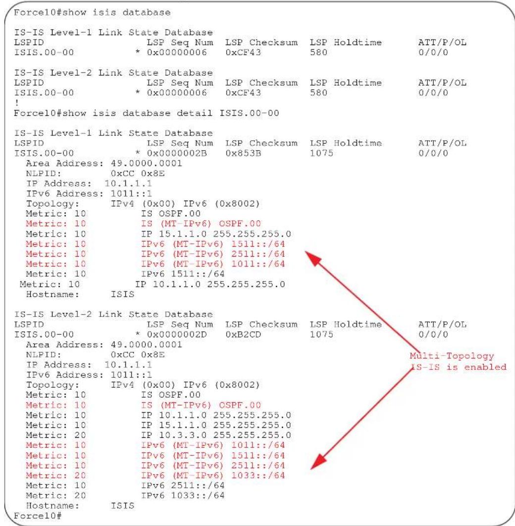
Table 29-1. Command Example Fields
| Field Description | |
| IS-IS Level-1/Level-2 Link State Database | Displays the IS-IS link state database for Level 1 or Level 2. |
| LSPID Displays the LSP identifier. | The first six octets are the System ID of the originating router.The next octet is the pseudonode ID. If this byte is not zero, then the LSP describes system links. If this byte is zero (0), then the LSP describes the state of the originating router.The designated router for a LAN creates and floods a pseudonode LSP and describes the attached systems.The last octet is the LSP number. An LSP will be divided into multiple LSP fragments if there is more data than cannot fit in a single LSP. Each fragment has a unique LSP number.An * after the LSPID indicates that an LSP was originated by the system where this command was issued. |
| LSP Seq Num This value is the sequence number for the LSP that allows other systems to determine if they have received the latest information from the source. | |
| LSP Checksum This is the checksum of the entire LSP packet. | |
| LSP Holdtime This value is the amount of time, in seconds, that the LSP remains valid. A zero holdtime indicates that this is a purged LSP and is being removed from the link state database. A value between brackets indicates the duration that the purged LSP stays in the database before being removed. | |
| ATT This value represents the Attach bit. This indicates that the router is a Level 2 router and can reach other areas. Level 1-only routers and Level 1-2 routers that have lost connection to other Level 2 routers use the Attach bit to find the closest Level 2 router. They point a default route to the closest Level 2 router. | |
| P This value represents the P bit. | This bit will always set be zero as Dell Force10 does not support area partition repair. |
| OL This value represents the overload bit, determining congestion. If the overload bit is set, other routers will not use this system as a transit router when calculating routes. |
show isis graceful-restart detail

Display detailed IS-IS Graceful Restart related settings.
Syntax
show isis graceful-restart detail
Command Modes
EXEC
EXEC Privilege
Command History
Version 8.3.1.0 Introduced on the E-Series
Example
Figure 29-5. Command Example: show isis graceful-restart detail
| Force10#show isis graceful-restart detail | |
| Configured Timer Value | |
| Graceful Restart | : Enabled |
| T3 Timer | : Manual |
| T3 Timeout Value | : 30 |
| T2 Timeout Value | : 30 (level-1), 30 (level-2) |
| T1 Timeout Value | : 5, retry count: 1 |
| Adjacency wait time | : 30 |
| Operational Timer Value | |
| Current Mode/State | : Normal/RUNNING |
| T3 Time left | : 0 |
| T2 Time left | : 0 (level-1), 0 (level-2) |
| Restart ACK rcv count | : 0 (level-1), 0 (level-2) |
| Restart Req rcv count | : 0 (level-1), 0 (level-2) |
| Suppress Adj rcv count | : 0 (level-1), 0 (level-2) |
| Restart CSNP rcv count | : 0 (level-1), 0 (level-2) |
| Database Sync count | : 0 (level-1), 0 (level-2) |
| Force10# | |
show isis hostname
E Display IS-IS host names configured or learned on the E-Series.
Syntax show isis hostname
Command Modes EXEC
EXEC Privilege
Example Figure 29-6. Command Example: show isis hostname
| Force10#show isis hostname | ||
| System Id | Dynamic Name | Static Name |
| *F100.E120.0013 | Force10 | ISIS |
| Force10# | ||
show isis interface
E Display detailed IS-IS interface status and configuration information.
Syntax show isis interface [interface]
Parameters
interface
(OPTIONAL) Enter the following keywords and slot/port or number information:
| For a 1-Gigabit Ethernet interface, enter the keywordGigabitEthernetfollowed by the slot/port information. |
| For Loopback interface, enter the keywordloopbackfollowed by a number from zero (0) to 16383. |
| For a Port Channel interface, enter the keywordport-channelfollowed by a number:C-Series and S-Series Range: 1-128E-Series Range: 1 to 32 for EtherScale, 1 to 255 for TeraScale and 1 to 512 for ExaScale. |
| For a SONET interface, enter the keywordsonetfollowed by the slot/port information. |
| For a 10-Gigabit Ethernet interface, enter the keywordTenGigabitEthernetfollowed by the slot/port information. |
| For a VLAN, enter the keywordvlanfollowed by a number from 1 to 4094. |
Command Modes
EXEC
EXEC Privilege
Example
Figure 29-7. Command Example: show isis interface (Partial)
Force10>show isis int
GigabitEthernet 0/7 is up, line protocol is up
MTU 1497, Encapsulation SAP
Routing Protocol: IS-IS
Circuit Type: Level-1-2
Interface Index 37847070, Local circuit ID 1
Level-1 Metric: 10, Priority: 64, Circuit ID: systest-3.01
Hello Interval: 10, Hello Multiplier: 3, CSNP Interval: 10
Number of active level-1 adjacencies: 1
Level-2 Metric: 10, Priority: 64, Circuit ID: systest-3.01
Hello Interval: 10, Hello Multiplier: 3, CSNP Interval: 10
Number of active level-2 adjacencies: 1
Next IS-IS LAN Level-1 Hello in 2 seconds
Next IS-IS LAN Level-2 Hello in 1 seconds
LSP Interval: 33
GigabitEthernet 0/8 is up, line protocol is up
MTU 1497, Encapsulation SAP
Routing Protocol: IS-IS
Circuit Type: Level-1-2
Interface Index 38371358, Local circuit ID 2
Level-1 Metric: 10, Priority: 64, Circuit ID: systest-3.02
Hello Interval: 10, Hello Multiplier: 3, CSNP Interval: 10
Number of active level-1 adjacencies: 1
Level-2 Metric: 10, Priority: 64, Circuit ID: systest-3.02
Hello Interval: 10, Hello Multiplier: 3, CSNP Interval: 10
--More--
show isis neighbors

Display information about neighboring (adjacent) routers.
Syntax
show isis neighbors [level-1 | level-2] [detail] [interface]
Parameters
| level-1 | (OPTIONAL) Displays information about Level 1 IS-IS neighbors. |
| level-2 | (OPTIONAL) Displays information about Level 2 IS-IS neighbors. |
| detail | (OPTIONAL) Displays detailed information about neighbors. |
| interface | (OPTIONAL) Identifies the interface type slot/port as one of the following:For a Gigabit Ethernet interface, enter the keywordGigabitEthernetfollowed by the slot/port information.For a Port Channel interface, enter the keywordport-channelfollowed by a number:C-Series and S-Series Range: 1-128E-Series Range: 1 to 32 for EtherScale, 1 to 255 for TeraScale and 1 to 512 for ExaScale.For a SONET interface, enter the keywordsonetfollowed by the slot/port information.For a 10-Gigabit Ethernet interface, enter the keywordTenGigabitEthernet followed by the slot/port information.For a VLAN, enter the keywordvlanfollowed by a number from 1 to 4094. |
Command Modes EXEC
EXEC Privilege
Example Figure 29-8. Command Example: show isis neighbors
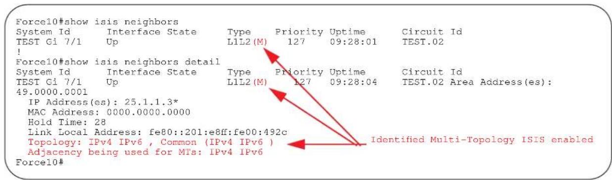
Table 29-2. show isis neighbors Command Example Fields
| Field Description | |
| System Id The value that identifies a system in an area. | |
| Interface The interface, slot, and port in which the router was discovered. | |
| State The value providing status about the adjacency state. The valid values are Up and Init. | |
| Type This value displays the adjacency type (Layer 2, Layer 2 or both). | |
| Priority IS-IS priority advertised by the neighbor. The neighbor with highest priority becomes the designated router for the interface. | |
| Uptime Displays the interfaces uptime. | |
| Circuit Id The neighbor's interpretation of the designated router for the interface. | |
Usage Information Use this command to confirm that the neighbor adjacencies are operating correctly. If you suspect that they are not, you can verify the specified area addresses of the routers by using the show isis neighbors command.
show isis protocol
E Display IS-IS routing information.
Syntax show isis protocol
Command Modes EXEC
EXEC Privilege
Example Figure 29-9. Command Example: show isis protocol
Force10#show isis protocol
IS-IS Router: <Null Tag>
    System Id: F100.E120.0013 IS-Type: level-1-2
    Manual area address(es):
    49.0000.0001
    Routing for area address(es):
    49.0000.0001
    Interfaces supported by IS-IS:
    GigabitEthernet 1/0 - IP - IPv6
    GigabitEthernet 1/1 - IP - IPv6
    GigabitEthernet 1/10 - IP - IPv6
    Loopback 0 - IP - IPv6
    Redistributing:
    Distance: 115
    Generate narrow metrics: level-1-2
    Accept narrow metrics: level-1-2
    Generate wide metrics: none
    Accept wide metrics: none
    Multi Topology Routing is enabled in transition mode.
    Force10#
show isis traffic
E This command enables you to display IS-IS traffic interface information.
Syntax show isis traffic [interface]
| Parameters | interface | (OPTIONAL) Identifies the interface type slot/port as one of the following:For a Gigabit Ethernet interface, enter the keywordGigabitEthernetfollowed by the slot/port information.For a Port Channel interface, enter the keywordport-channelfollowed by a number:C-Series and S-Series Range: 1-128E-Series Range: 1 to 32 for EtherScale, 1 to 255 for TeraScale and 1 to 512 for ExaScale.For a SONET interface, enter the keywordsonetfollowed by the slot/port information.For a 10-Gigabit Ethernet interface, enter the keywordTenGigabitEthernet followed by the slot/port information.For a VLAN, enter the keywordvlanfollowed by a number from 1 to 4094. |
Command Modes EXEC
EXEC Privilege
Example
Figure 29-10. Command Example: show isis traffic
Force10#sho is traffic
IS-IS: Level-1 Hellos (sent/rcvd) : 0/721
IS-IS: Level-2 Hellos (sent/rcvd) : 900/943
IS-IS: PTP Hellos (sent/rcvd) : 0/0
IS-IS: Level-1 LSPs sourced (new/refresh) : 0/0
IS-IS: Level-2 LSPs sourced (new/refresh) : 1/3
IS-IS: Level-1 LSPs flooded (sent/rcvd) : 0/0
IS-IS: Level-2 LSPs flooded (sent/rcvd) : 5934/5217
IS-IS: Level-1 LSPs CSNPs (sent/rcvd) : 0/0
IS-IS: Level-2 LSPs CSNPs (sent/rcvd) : 472/238
IS-IS: Level-1 LSPs PSNPs (sent/rcvd) : 0/0
IS-IS: Level-2 LSPs PSNPs (sent/rcvd) : 10/337
IS-IS: Level-1 DR Elections : 4
IS-IS: Level-2 DR Elections : 4
IS-IS: Level-1 SPF Calculations : 0
IS-IS: Level-2 SPF Calculations : 389
IS-IS: LSP checksum errors received : 0
IS-IS: LSP authentication failures : 0
Force10#
Table 29-3. Command Example Fields
| Item Description | |
| Level-1/Level-2 Hellos (sent/rcvd) Displays the number of Hello packets sent and received. | |
| PTP Hellos (sent/rcvd) Displays the number of point-to-point Hellos sent and received. | |
| Level-1/Level-2 LSPs sourced (new/refresh) | Displays the number of new and refreshed LSPs. |
| Level-1/Level-2 LSPs flooded (sent/rcvd) | Displays the number of flooded LSPs sent and received. |
| Level-1/Level-2 LSPs CSNPs (sent/rcvd) | Displays the number of CSNP LSPs sent and received. |
| Level-1/Level-2 LSPs PSNPs (sent/rcvd) | Displays the number of PSNP LPSs sent and received. |
| Level-1/Level-2 DR Elections Displays the number of times designated router elections ran. | |
| Level-1/Level-2 SPF Calculations Displays the number of shortest path first calculations. | |
| LSP checksum errors received Displays the number of checksum errors LSPs received. | |
| LSP authentication failures Displays the number of LSP authentication failures. | |
spf-interval
E
Specify the minimum interval between Shortest Path First (SPF) calculations.
Syntax
spf-interval [level-1 | level-2] interval seconds [initial_wait_interval seconds [second_wait_interval seconds]]
To restore default values, use the no spf-interval [level-1 | level-2] interval seconds [initial_wait_interval seconds [second_wait_interval seconds]] command.
Parameters
| level-1 | (OPTIONAL) Enter the keyword level-1 to apply the configuration to Level-1 SPF calculations. |
| level-2 | (OPTIONAL) Enter the keyword level-2 to apply the configuration to Level-2 SPF calculations. |
| interval seconds | Enter the maximum number of seconds between SPF calculations.Range: 0 to 120 secondsDefault: 10 seconds |
| initial_wait_interval seconds | (OPTIONAL) Enter the initial wait time, in seconds, before running the first SPF calculations.Range: 0 to 120 secondsDefault: 5 second |
| second_wait_interval seconds | (OPTIONAL) Enter the wait interval, in seconds, between the first and second SPF calculations.Range: 0 to 120 secondsDefault: 5 seconds |
Defaults
Defaults as above
Command Modes
ROUTER ISIS (for IPv4)
CONFIGURATION-ROUTER-ISIS-ADDRESS-FAMILY-IPV6 (for IPv6)
Command History
Version 7.8.1.0 Introduced to support MT ISIS
Version 7.5.1.0 Expanded to support SPF Throttling Enhancement
Usage Information
This command spf-interval in CONFIG-ROUTER-ISIS-AF-IPV6 mode is used for IPv6 Multi-Topology route computation only. If using single topology mode, use the spf-interval command in CONFIG-ROUTER-ISIS mode for both IPv4 and IPv6 route computations.
SPF throttling slows down the frequency at which route calculation are performed during network instability. Even though throttling route calculations slows down network convergence, not throttling can result in a network not functioning as expected. If network topology is unstable, throttling slows down the scheduling of route calculations until the topology regains its stability.
The first route calculation is controlled by the initial wait interval and the second calculation is controlled by the second wait interval. Each subsequent wait interval is twice as long as the previous one until the wait interval reaches the maximum wait time specified (interval seconds). Once the network calms down and there are no triggers for two times the maximum interval, fast behavior is restored (the initial wait time).
Link Aggregation Control Protocol (LACP)
Overview
This chapter contains commands for Dell Force10's implementation of Link Aggregation Control Protocol (LACP) for the creation of dynamic link aggregation groups (LAGs — called port-channels in FTOS parlance). For static LAG commands, see the section Port Channel Commands in the Interfaces chapter), based on the standards specified in the IEEE 802.3 Carrier sense multiple access with collision detection (CSMA/CD) access method and physical layer specifications.
Commands in this chapter generally are supported on all three Dell Force10 platforms — C-Series, E-Series, and S-Series — as indicated by the following symbols under command headings: C E S
Commands
Use the following commands for LACP:
- clear lacp counters
- debug lacp
- lacp long-timeout
- lacp port-priority
- lacp system-priority
- port-channel mode
• port-channel-protocol lacp
• show lacp
In addition, an FTOS option provides hitless dynamic LACP states (no noticeable impact to dynamic LACP states after an RPM failover) on E-Series. See redundancy protocol in the High Availability chapter.
clear lacp counters

Clear Port Channel counters.
Syntax
clear lacp port-channel-number counters
Parameters
| port-channel-number | Enter a port-channel number: |
| C-Series and S-Series Range: 1-128 | |
| E-Series Range: 1 to 32 for EtherScale, 1 to 255 for TeraScale and 1 to 512 for ExaScale. |
| Defaults | Without a Port Channel specified, the command clears all Port Channel counters. |
| Command Modes | EXEC |
| EXEC Privilege | |
| Command History | Version 7.6.1.0 Support added for S-Series |
| Version 7.5.1.0 Support added for C-Series | |
| Version 6.2.1.1 Introduced on E-Series | |
| Related Commands | show lacp Display the lacp configuration |
debug lacp

Debug LACP (configuration, events etc.)
Syntax
debug lacp [config | events | pdu [in | out | [interface [in | out]]]]
To disable LACP debugging, use the no debug lacp [config | events | pdu [in | out | [interface [in | out]]]] command.
Parameters
| config | (OPTIONAL) Enter the keyword config to debug the LACP configuration. |
| events | (OPTIONAL) Enter the keyword events to debug LACP event information. |
| pdu in | out | (OPTIONAL) Enter the keyword pdu to debug LACP Protocol Data Unit information. Optionally, enter an in or out parameter to:Receive enter inTransmit enter out |
| interface in | out | (OPTIONAL) Enter the following keywords and slot/port or number information:For a 100/1000 Ethernet interface, enter the keyword GigabitEthernet followed by the slot/port information.For a Gigabit Ethernet interface, enter the keyword GigabitEthernet followed by the slot/port information.For a SONET interface, enter the keyword sonet followed by the slot/port information.For a Ten Gigabit Ethernet interface, enter the keyword TenGigabitEthernet followed by the slot/port information.Optionally, enter an in or out parameter:Receive enter inTransmit enter out |
Defaults
This command has no default values or behavior
Command Modes
EXEC
EXEC Privilege
Command History
Version 7.6.1.0 Support added for S-Series
Version 7.5.1.0 Support added for C-Series
Version 6.2.1.1 Introduced on E-Series
Iacp long-timeout
| C E | Configure a long timeout period (30 seconds) for an LACP session. |
| Syntax | Iacp long-timeoutTo reset the timeout period to a short timeout (1 second), use theno lacplong-timeoutcommand. |
| Defaults | 1 second |
| Command Modes | INTERFACE (conf-if-po-number) |
| Command History | Version 7.6.1.0 Support added for S-Series |
| Version 7.5.1.0 Support added for C-Series | |
| Version 7.5.1.0 Introduced on E-Series | |
| Usage Information | This command applies to dynamic port-channel interfaces only. When applied on a static port-channel, the command has no effect. |
| Related Commands | show lacp Display the lacp configuration |
lapc port-priority
| C E S | Configure the port priority to influence which ports will be put in standby mode when there is a hardware limitation that prevents all compatible ports from aggregating. | |
| Syntax | lacp port-priority priority-value | |
| To return to the default setting, use the no lacp port-priority priority-value command. | ||
| Parameters | priority-value | Enter the port-priority value. The higher the value number the lower the priority.Range: 1 to 65535Default: 32768 |
| Defaults | 32768 | |
| Command Modes | INTERFACE | |
| Command History | Version 7.6.1.0 Support added for S-Series | |
| Version 7.5.1.0 Support added for C-Series | ||
| Version 6.2.1.1 Introduced on E-Series | ||
lapc system-priority

Configure the LACP system priority.
Syntax
| Parameters | priority-value | Enter the system-priority value. The higher the value, the lower the priority.Range: 1 to 65535Default: 32768 |
| Defaults | 32768 | |
| and Modes | CONFIGURATION | |
| Command History | Version 7.6.1.0 Support added for S-Series | |
| Version 7.5.1.0 Support added for C-Series | ||
| Version 6.2.1.1 Introduced on E-Series | ||
port-channel mode

Configure the LACP port channel mode.
Syntax
| Parameters | number | Enter the keyword port-channel followed by a number:C-Series and S-Series Range: 1-128E-Series Range: 1 to 32 for EtherScale, 1 to 255 for TeraScale and 1 to 512 for ExaScale. |
| active | Enter the keyword active to set the mode to the active state.* | |
| passive | Enter the keyword passive to set the mode to the passive state.* | |
| off Enter the keyword off to set the mode to the off state.* | ||
| * The LACP modes are defined in the table below. | ||
| Defaults | off | |
| mand Modes | INTERFACE | |
| Command History | Version 7.6.1.0 Support added for S-Series | |
| Version 7.5.1.0 Support added for C-Series | ||
| Version 6.2.1.1 Introduced | ||
| Usage Information | The LACP modes are defined in the following table. | |
Table 30-1. LACP Modes
| Mode Function | |
| active | An interface is in an active negotiating state in this mode. LACP runs on any link configured in the active state and also automatically initiates negotiation with other ports by initiating LACP packets. |
| passive | An interface is not in an active negotiating state in this mode. LACP runs on any link configured in the passive state. Ports in a passive state respond to negotiation requests from other ports that are in active states. Ports in a passive state respond to LACP packets. |
| off | An interface can not be part of a dynamic port channel in the off mode. LACP will not run on a port configured in the off mode. |
port-channel-protocol lacp

Enable LACP on any LAN port.
Syntax
port-channel-protocol lacp
To disable LACP on a LAN port, use the no port-channel-protocol lacp command.
Command Modes
INTERFACE
Command History
Version 6.2.1.1 Introduced
Related Commands
show lacp Display the LACP information.
show interfaces port-channel Display information on configured Port Channel groups.
show lacp

Display the LACP matrix.
Syntax
show lacp port-channel-number [sys-id | counters]
Parameters
| port-channel-number | Enter a port-channel number:C-Series and S-Series Range: 1-128E-Series Range: 1 to 32 for EtherScale, 1 to 255 for TeraScale and 1 to 512 for ExaScale. |
| sys-id | (OPTIONAL) Enter the keyword sys-id and the value that identifies a system. |
| counters | (OPTIONAL) Enter the keyword counters to display the LACP counters. |
Command Modes
EXEC
EXEC Privilege
Command History
Version 7.6.1.0 Support added for S-Series
Version 7.5.1.0 Support added for C-Series
Version 6.2.1.1 Introduced
Example 1 Figure 30-1. show lacp port-channel-number command
Force10#show lacp 1
Port-channel 1 admin up, oper up, mode lacp
Actor System ID: Priority 32768, Address 0001.e800.a12b
Partner System ID: Priority 32768, Address 0001.e801.45a5
    Actor Admin Key 1, Oper Key 1, Partner Oper Key 1
    LACP LAG 1 is an aggregatable link

A - Active LACP, B - Passive LACP, C - Short Timeout, D - Long Timeout
E - Aggregatable Link, F - Individual Link, G - IN_SYNC, H - OUT_OF_SYNC
I - Collection enabled, J - Collection disabled, K - Distribution enabled L - Distribution disabled,
M - Partner Defaulted, N - Partner Non-defaulted, O - Receiver is in expired state,
P - Receiver is not in expired state

Port Gi 10/6 is enabled, LACP is enabled and mode is lacp
    Actor Admin: State ACEHJLMP Key 1    Priority 128
    Oper: State ACEGIKNP Key 1    Priority 128
    Partner Admin: State BDFHJLMP Key 0    Priority 0
    Oper: State BCEGIKNP Key 1    Priority 128
Force10#
Example 2 Figure 30-2. show lacp sys-id command Example
Force10#show lacp 1 sys-id
Actor System ID: Priority 32768, Address 0001.e800.al2b
Partner System ID: Priority 32768, Address 0001.e801.45a5
Force10#
Example 3 Figure 30-3. show lacp counter command Example
Force10#show lacp 1 counters
Port Xmit LACP PDU Recv Marker PDU Xmit Recv Unknown Pkts Rx Illegal Pkts Rx
Gi 10/6 200 200 0 0 0 0
Force10#
Related Commands
clear lacp counters Clear the LACP counters.
show interfaces port-channel Display information on configured Port Channel groups.
Layer 2
Overview
This chapter describes commands to configure Layer 2 features. It contains the following sections:
• MAC Addressing Commands
• Virtual LAN (VLAN) Commands
Some MAC addressing commands are supported only on the E-Series, some on all three Dell Force10 platforms and some on two Dell Force10 platforms. Support is indicated by these characters, where appropriate, under each command heading: C E S
The VLAN commands are supported on all three Dell Force10 platforms — C E S
MAC Addressing Commands
The following commands are related to configuring, managing, and viewing MAC addresses:
- clear mac-address-table dynamic
• mac accounting destination
• mac-address-table aging-time
• mac-address-table static
• mac-address-table station-move threshold
• mac-address-table station-move time-interval
• mac-address-table station-move refresh-arp
• mac cam fib-partition - mac learning-limit
• mac learning-limit learn-limit-violation
• mac learning-limit station-move-violation
• mac learning-limit reset
• show cam mac linecard (count)
• show cam maccheck linecard
• show cam mac linecard (dynamic or static)
• show cam mac stack-unit
• show mac-address-table
• show mac-address-table aging-time
• show mac accounting destination
• show mac cam
• show mac learning-limit
clear mac-address-table dynamic

Clear the MAC address table of all MAC address learned dynamically.
Syntax
clear mac-address-table dynamic {address mac-address | all | interface interface | vlan vlan-id}
Parameters
| address mac-address | Enter the keyword address followed by a MAC address in nn:nn:nn:nn:nn:nn format. |
| all | Enter the keyword all to delete all MAC address entries in the MAC address table. |
| interface interface | Enter the following keywords and slot/port or number information:For a 1-Gigabit Ethernet interface, enter the keywordGigabitEthernet followed by the slot/port information.For a Port Channel interface, enter the keyword port-channel followed by a number:C-Series and S-Series Range: 1-128E-Series Range: 1 to 32 for EtherScale, 1 to 255 for TeraScale and 1 to 512 for ExaScale.For a SONET interface, enter the keyword sonet followed by the slot/port information.For a 10-Gigabit Ethernet interface, enter the keywordTenGigabitEthernet followed by the slot/port information. |
| vlan vlan-id | Enter the keyword vlan followed by a VLAN ID number from 1 to 4094. |
Command Modes
EXEC Privilege
Command History
Version 7.6.1.0 Introduced on S-Series
Version 7.5.1.0 Introduced on C-Series
pre-Version 6.1.1.1 Introduced on E-Series
mac accounting destination

Configure a destination counter for Layer 2 traffic.
Syntax
mac accounting destination { mac-address vlan vlan-id | vlan} [bytes | packets]
To delete a destination counter, enter no mac accounting destination.
Parameters
| mac-address | Enter the MAC address in the nn:nn:nn:nn:nn:nn format to count Layer 2 packets or bytes sent to that MAC address. |
| vlan vlan-id | Enter the keywordvlan followed by the VLAN ID to count Layer 2 packets or bytes sent to the VLAN.Range: 1 to 4094. |
| bytes (OPTIONAL) Enter the keywordbytes to count only bytes | |
| packets | (OPTIONAL) Enter the keywordpackets to count only packets. |
| Defaults | Not configured. |
| Command Modes | INTERFACE (available on physical interfaces only) |
| Command History | Version 7.4.1.0 Introduced on E-Series |
| Usage Information | You must place the interface in Layer 2 mode (using the switchport command) prior to configuring the mac accounting destination command. |
mac-address-table aging-time

Specify an aging time for MAC addresses to be removed from the MAC Address Table.
Syntax
mac-address-table aging-time seconds
| Parameters | seconds | Enter either zero (0) or a number as the number of seconds before MAC addresses are relearned. To disable aging of the MAC address table, enter 0.E-Series Range from CONFIGURATION mode: 10 - 1000000E-Series Range from INTERFACE VLAN mode: 1 - 1000000C-Series and S-Series Range: 10 - 1000000Default: 1800 seconds |
| Defaults | 1800 seconds | |
| Command Modes | CONFIGURATION | |
| INTERFACE VLAN (E-Series only) | ||
| Command History | Version 8.3.1.0 On the E-Series, available in INTERFACE VLAN context and reduced minimum aging time in INTERFACE VLAN context from 10 seconds to 1 second. | |
| Version 7.6.1.0 Introduced on S-Series | ||
| Version 7.5.1.0 Introduced on C-Series | ||
| pre-Version 6.2.1.1 Introduced on E-Series | ||
| Related Commands | mac learning-limit Set the MAC address learning limits for a selected interface. | |
| show mac-address-table aging-time Display the MAC aging time. | ||
mac-address-table static

Associate specific MAC or hardware addresses to an interface and VLANs.
Syntax
mac-address-table static mac-address output interface vlan vlan-id
To remove a MAC address, use the no mac-address-table static mac-address output interface vlan vlan-id command.
| Parameters | mac-address | Enter the 48-bit hexadecimal address in nn:nn:nn:nn:nn:nn format. |
| output interface | Enter the keyword output followed by one of the following interfaces:For a 1-Gigabit Ethernet interface, enter the keywordGigabitEthernet followed by the slot/port information.For a Port Channel interface, enter the keyword port-channelfollowed by a number:C-Series and S-Series Range: 1-128E-Series Range: 1 to 32 for EtherScale, 1 to 255 for TeraScale and 1 to 512 for ExaScale.For a SONET interface, enter the keyword sonet followed by the slot/port information.For a 10-Gigabit Ethernet interface, enter the keywordTenGigabitEthernet followed by the slot/port information. | |
| vlan vlan-id | Enter the keyword vlan followed by a VLAN ID.Range:1 to 4094. | |
| Defaults | Not configured. | |
| hand Modes | CONFIGURATION | |
| Command History | Version 7.6.1.0 Introduced on S-Series | |
| Version 7.5.1.0 Introduced on C-Series | ||
| pre-Version 6.2.1.1 Introduced on E-Series | ||
| Related Commands | show mac-address-table Displays the MAC address table. | |
mac-address-table station-move threshold

Change the frequency with which the MAC address station-move trap is sent after a MAC address changes in a VLAN. A trap is sent if a station move is detected above a threshold number of times in a given interval.
Syntax
[no] mac-address-table station-move threshold number interval count
| Parameters | threshold number | Enter the keyword threshold followed by the number of times MAC addresses in VLANs can change before an SNMP trap is sent. Range: 1 to 10 |
| interval seconds | Enter the keyword interval followed by the number of seconds. Range: 5 to 60 | |
| Defaults | Not configured. | |
| mand Modes | CONFIGURATION | |
| Command History | Version 7.5.1.0 Introduced on C-Series | |
| pre-Version 6.2.1.1 Introduced on E-Series | ||
Usage Information
For information on the specific trap sent and the corresponding Syslog refer to Appendix, .
mac-address-table station-move time-interval

Reduce the amount of time FTOS takes to detect aged entries and station moves.
Syntax
[no] mac-address-table station-move time-interval number
| Parameters | time-interval number | Select the interval of the successive scans of the MAC address table that are used to detect a aged entries and station moves. Range: 500 to 5000ms |
| Defaults | 5000ms | |
| Command Modes | CONFIGURATION | |
| Command History | Version 7.8.1.0 Introduced on E-Series | |
| Usage Information | FTOS takes 4 to 5 seconds to detect aged entries and station moves because the MAC address table scanning routine runs every 5000 ms by default. To achieve faster detection, reduce the scanning interval. | |
mac-address-table station-move refresh-arp

Ensure that ARP refreshes the egress interface when a station move occurs due to a topology change.
Syntax
[no] mac-address-table station-move refresh-arp
| Defaults | No default values or behavior |
| Command Modes | CONFIGURATION |
| Command History | Version 7.7.1.0 Introduced on S-Series |
| Version 7.6.1.0 Introduced on C-Series | |
| Version 7.4.1.0 Introduced on E-Series | |
| Usage Information | See the “NIC Teaming” section of the Layer 2 chapter in the FTOS Configuration Guide for details on using this command. |
mac cam fib-partition

Reapportion the amount of Content Addressable Memory (CAM) available for MAC address learning (FIB) versus the amount available for MAC ACLs on a line card.
Syntax
mac cam fib-partition {25 | 50 | 75 | 100} slot-number
To return to the default setting, enter no mac cam fib-partition.
Parameters
| 25 | Enter the keyword 25 to set aside 25% of the CAM for MAC address learning. |
| 50 | Enter the keyword 50 to set aside 50% of the CAM for MAC address learning. |
| 75 | Enter the keyword 75 to set aside 75% of the CAM for MAC address learning. |
| 100 | Enter the keyword 100 to set aside 100% of the MAC CAM for MAC address learning.With this configuration, no MAC ACLs are processed. |
| slot-number | Enter the line card slot number.Range: 0 to 13 for the E12000 to 6 for the E6000 to 5 for the E300 |
Defaults
75 (75% of the MAC CAM for MAC address learning)
Command Modes
CONFIGURATION
Usage Information
After setting the CAM partition size, the line card resets.
Related Commands
show mac cam Display the current MAC CAM partition values.
mac learning-limit

Limit the maximum number of MAC addresses (static + dynamic) learned on a selected interface.

Note: Sticky MAC is not supported on the S25 or S50 in FTOS release 8.4.2.6.
Syntax
mac learning-limit address_limit [vlan vlan-id] [dynamic] [no-station-move | station-move] [sticky]
Parameters
| address_limit | Enter the maximum number of MAC addresses that can be learned on the interface. Range: 1 to 1000000 |
| vlan vlan-id | E-Series only: Enter the keyword followed by the VLAN ID. Range: 1-4094 |
| dynamic | (OPTIONAL) Enter the keyword dynamic to allow aging of MACs even though a learning limit is configured. |
| no-station-move | (OPTIONAL) Enter the keyword no-station-move to disallow a station move (associate the learned MAC address with the most recently accessed port) on learned MAC addresses. |
| station-move | (OPTIONAL) Enter the keyword station-move to allow a station move on learned MAC addresses. |
| sticky | (OPTIONAL) C-Series and S-Series only: Enter the keyword sticky to enable sticky MAC-address learning, which converts dynamically-learned MAC addresses on a port or port-channel interface to “sticky” MAC addresses that prevent trusted devices from moving to a different interface. |
Defaults
On C-Series, the default behavior is no-station-move + static.
On E-Series, the default behavior is station-move + static.
“Static” means manually entered addresses, which do not age.
Command Modes
INTERFACE
Command History
| Version 8.4.2.3 | Added the sticky option on the C-Series and S-Series. |
| Version 8.3.1.0 | Added vlan option on E-Series. |
| Version 8.2.1.0 Introduced on S-Series | |
| Version 7.7.1.0 | Introduced on C-Series; added station-move option |
| Version 6.5.1.0 Added support for MAC Learning-Limit on LAG | |
Usage Information
This command and its options are supported on physical interfaces, static LAGs, LACP LAGs, and VLANs.
If the vlan option is not specified, then the MAC address counters is not VLAN-based. That is, the sum of the addresses learned on all VLANs (not having any learning limit configuration) is counted against the MAC learning limit.
MAC Learning Limit violation logs and actions are not available on a per-VLAN basis.
With the keyword no-station-move option, MAC addresses learned through this feature on the selected interface will persist on a per-VLAN basis, even if received on another interface. Enabling or disabling this option has no effect on already learned MAC addresses.
Once the MAC address learning limit is reached, the MAC addresses do not age out unless you add the dynamic option. To clear statistics on MAC address learning, use the clear counters command with the learning-limit parameter.

Note: If you configure this command on an interface in a routed VLAN, and once the MAC addresses learned reaches the limit set in the mac learning-limit command, IP protocols are affected. For example, VRRP sets multiple VRRP Masters, and OSPF may not come up.
When a channel member is added to a port-channel and there is not enough ACL CAM space, then the MAC limit functionality on that port-channel is undefined. When this occurs, un-configure the existing configuration first and then reapply the limit with a lower value.
When you enable sticky MAC-address learning (sticky), dynamically-learned MAC addresses of trusted devices are added to the running configuration and “stick” to the port or VLAN on which they are learned even if an interface goes down and comes back up. If you save sticky MAC addresses to the start-up configuration file by entering the write config command, the addresses are deleted from the running-configuration, do not have to be dynamically relearned, and do not change when the switch reboots. Any sticky MAC addresses learned after the write config is performed are not saved after a reboot.
| Related Commands | clear counters | Clear counters used in the show interface command |
| clear mac-address-table dynamic | Clear the MAC address table of all MAC address learned dynamically. | |
| show mac learning-limit Display MAC learning-limit configuration. | ||
mac learning-limit learn-limit-violation

Configure an action for a MAC address learning-limit violation.
Syntax
mac learning-limit learn-limit-violation {log | shutdown}
To return to the default, use the no mac learning-limit learn-limit-violation {log | shutdown} command.
| Parameters | log | Enter the keyword log to generate a syslog message on a learning-limit violation. |
| shutdown | Enter the keyword shutdown to shut down the port on a learning-limit violation. | |
| Defaults | No default behavior or values | |
| mand Modes | INTERFACE (conf-if-interface-slot/port) | |
| Command History | Version 8.2.1.0 Introduced on S-Series | |
| Version 7.8.1.0 Introduced on C-Series | ||
| Version 7.5.1.0 Introduced on E-Series | ||
| Usage Information | This is supported on physical interfaces, static LAGs, and LACP LAGs. | |
| Related Commands | show mac learning-limit Display details of the mac learning-limit | |
mac learning-limit station-move-violation

Specify the actions for a station move violation.
Syntax
mac learning-limit station-move-violation {log | shutdown-both | shutdown-offending | shutdown-original}
To disable a configuration, use the no mac learning-limit station-move-violation command, followed by the configured keyword.
Parameters
| log | Enter the keyword log to generate a syslog message on a station move violation. |
| shutdown-both | Enter the keyword shutdown to shut down both the original and offending interface and generate a syslog message. |
| shutdown-offending | Enter the keyword shutdown-offending to shut down the offending interface and generate a syslog message. |
| shutdown-original | Enter the keyword shutdown-original to shut down the original interface and generate a syslog message. |
Defaults
No default behavior or values
Command Modes
INTERFACE (conf-if-interface-slot/port)
Command History
Version 8.2.1.0 Introduced on S-Series
Version 7.8.1.0 Introduced on C-Series
Version 7.5.1.0 Introduced on E-Series
Usage Information
This is supported on physical interfaces, static LAGs, and LACP LAGs.
Related Commands
show mac learning-limit Display details of the mac learning-limit
mac learning-limit reset

Reset the MAC address learning-limit error-disabled state.
Syntax
mac learning-limit reset
Defaults
No default behavior or values
Command Modes
EXEC
EXEC Privilege
Command History
Version 8.2.1.0 Introduced on S-Series
Version 7.7.1.0 Introduced on C-Series
Version 7.5.1.0 Introduced on E-Series
show cam mac linecard (count)

Display the CAM size and the portions allocated for MAC addresses and for MAC ACLs.
Syntax
show cam mac linecard slot port-set port-pipe count [vlan vlan-id] [interface interface]
| Parameters | linecard slot | (REQUIRED) Enter the keyword linecard followed by a slot number to select the linecard for which to gather information.E-Series range: 0 to 6. |
| port-set port-pipe | (REQUIRED) Enter the keyword port-set followed by a Port-Pipe number to select the Port-Pipe for which to gather information.E-Series range: 0 or 1 | |
| count | (REQUIRED) Enter the keyword count to display CAM usage by interface type. | |
| interface interface | (OPTIONAL) Enter the keyword interface followed by the interface type, slot and port information:For a 1-Gigabit Ethernet interface, enter the keywordGigabitEthernet followed by the slot/port information.For a Port Channel interface, enter the keyword port-channel followed by a number:E-Series Range: 1 to 32 for EtherScale, 1 to 255 for TeraScale and 1 to 512 for ExaScale.For a SONET interface, enter the keyword sonet followed by the slot/port information.For a 10-Gigabit Ethernet interface, enter the keywordTenGigabitEthernet followed by the slot/port information. | |
| vlan vlan-id | (OPTIONAL) Enter the keyword vlan followed by the VLAN ID to display the MAC address assigned to the VLAN.Range: 1 to 4094. | |
| hand Modes | EXEC | |
| EXEC Privilege | ||
| Command History | pre-Version 6.2.1.1 Introduced on E-Series | |
show cam maccheck linecard

Display the results of the BCMI2 check command.
Syntax
show cam maccheck linecard slot port-set port-pipe
| Parameters | linecard slot | (REQUIRED) Enter the keyword linecard followed by a slot number to select the linecard for which to gather information.C300 range: 0 to 7; C150 range: 0 to 4 |
| port-set port-pipe | (REQUIRED) Enter the keyword port-set followed by a Port-Pipe number to select the Port-Pipe for which to gather information.Range: 0 or 1 |
Command Modes
EXEC
EXEC Privilege
Command History
Version 7.6.1.0 Introduced on C-Series
Example
Figure 31-1. show cam maccheck linecard Command Output Example
Force10#show cam maccheck linecard 2 port-set 0
Dumping entries. From 0 to 16383.
Progress . marks 100 memory table entries.
....Index 5576 (0x15c8) has valid entries (H: 2b9, E: 0)

<MAC_ADDR=0xffffffffffff, VLAN_ID=0xff, PRI=0, CPU=0, DST_DISCARD=0, SRC_DISCARD=0, SCP=0, TGID_LO=0, PORT_TGID=0, TGID_PORT=0, T=0, TGID_HI=0, L2MC_PTR=0, MODULE_ID=0, REMOTE_T RUNK=0, L3=0, MAC_BLOCK_INDEX=0, STATIC_BIT=1, RPE=0, MIRROR=0, VALID=1, EVEN_PARITY=0, HI TDA=0, HITSA=0>
....Index 6592 (0x19c0) has valid entries (H: 338, E: 0)

<MAC_ADDR=0xa0000000, VLAN_ID=0xffe, PRI=0, CPU=0, DST_DISCARD=0, SRC_DISCARD=0, SCP=0, TGID_LO=0, PORT_TGID=0, TGID_PORT=0, T=0, TGID_HI=0, L2MC_PTR=0, MODULE_ID=0x10, REMOTE_TR UNK=0, L3=0, MAC_BLOCK_INDEX=0, STATIC_BIT=0, RPE=0, MIRROR=0, VALID=1, EVEN_PARITY=1, HIT DA=1, HITSA=1>

!----output truncated----!
Usage Information
Use this command to check various flags associated with each MAC address in the CAM.
Figure 31-1 shows information for two MAC addresses. The second entry is for MAC address 00:00:a0:00:00:00 (leading 0s are not shown), which is shown as learned on VLAN ID 4094 (0xffff), as shown below in Figure 31-2 and Figure 31-3. Above, “STATIC_BIT=0” means that the address is dynamically learned.
When an entry is listed as STATIC_BIT=1, its HIT_SA is 0, which signifies that this address is not getting continuously learned trough traffic. The HIT_DA is set when a new learn happens, and after the first age sweep, it gets reset.
Example
Figure 31-2. show mac-address-table Command Output Example
Force10#show mac-address-table
VlanId Mac Address Type Interface State
4094 00:00:a0:00:00:00 Dynamic Gi 2/0 Active
!----output truncated----!
Example
Figure 31-3. show cam mac linecard Command Output Example
Force10#show cam mac linecard 2 port-set 0
VlanId Mac Address Region Interface
0 ff:ff:ff:ff:ff STATIC 00001
4094 00:00:a0:00:00:00 DYNAMIC Gi 2/0
!----output truncated----!
show cam mac linecard (dynamic or static)

Display the CAM size and the portions allocated for MAC addresses and for MAC ACLs.
Syntax
show cam mac linecard slot port-set port-pipe [address mac_addr | dynamic | interface interface | static | vlan vlan-id]
| Parameters | linecard slot | (REQUIRED) Enter the keyword linecard followed by a slot number to select the linecard for which to gather information.C-Series Range: 0 to 4 (C150); 0 to 8 (C300)E-Series Range: 0 to 6 |
| port-set port-pipe | (REQUIRED) Enter the keyword port-set followed by a Port-Pipe number to select the Port-Pipe for which to gather information.Range: 0 or 1 | |
| address mac-addr | (OPTIONAL) Enter the keyword address followed by a MAC address in the nn:nn:nn:nn:nn:nn format to display information on that MAC address. | |
| dynamic | (OPTIONAL) Enter the keyword dynamic to display only those MAC addresses learned dynamically by the switch. | |
| interface interface | (OPTIONAL) Enter the keyword interface followed by the interface type, slot and port information:For a 1-Gigabit Ethernet interface, enter the keyword GigabitEthernet followed by the slot/port information.For a Port Channel interface, enter the keyword port-channel followed by a number:C-Series Range: 1-128E-Series Range: 1 to 32 for EtherScale, 1 to 255 for TeraScale and 1 to 512 for ExaScale.For a SONET interface, enter the keyword sonet followed by the slot/port information.For a 10-Gigabit Ethernet interface, enter the keyword TenGigabitEthernet followed by the slot/port information. | |
| static | (OPTIONAL) Enter the keyword static to display only those MAC address specifically configured on the switch. | |
| vlan vlan-id | (OPTIONAL) Enter the keyword vlan followed by the VLAN ID to display the MAC address assigned to the VLAN.Range: 1 to 4094. | |
| Command Modes | EXEC | |
| EXEC Privilege | ||
| Command History | Version 7.5.1.0 Added support for C-Series | |
| pre-Version 6.2.1.1 Introduced on E-Series | ||
Example
Figure 31-4. show cam mac linecard Command Example
| Forcel0#show cam mac linecard 1 port-set 0 | |||||
| Port - (TableID) assignments: | |||||
| 00(01) | 01(01) | 02(01) | 03(01) | 04(01) | 05(01) |
| 12(01) | 13(01) | 14(01) | 15(01) | 16(01) | 17(01) |
| Index Table ID VlanId Mac Address Region Interface | |||||
| 0 | 1 | 0 | 00:01:e8:0d:b7:3b | LOCAL_DA | 1e000 |
| 1 | 1 | 0 | 00:01:e8:0d:b7:3a | LOCAL_DA | 1e000 |
| 101 | 0 | 0 | 00:01:e8:00:04:00 | SYSTEM_STATIC | 01c05 |
| 102 | 0 | 0 | 01:80:00:00:00:00 | SYSTEM_STATIC | 01c05 |
| 103 | 0 | 0 | 01:00:0c:cc:cc:cc | SYSTEM_STATIC | 01c01 |
| 104 | 0 | 0 | 01:80:c2:00:00:02 | SYSTEM_STATIC | 01c02 |
| 105 | 0 | 0 | 01:80:c2:00:00:0e | SYSTEM_STATIC | 01c01 |
| 106 | 0 | 0 | 00:01:e8:0d:b7:68 | SYSTEM_STATIC | DROP |
| 107 | 0 | 0 | 00:01:e8:0d:b7:67 | SYSTEM_STATIC | DROP |
| 108 | 0 | 0 | 00:01:e8:0d:b7:66 | SYSTEM_STATIC | DROP |
| 109 | 0 | 0 | 00:01:e8:0d:b7:65 | SYSTEM_STATIC | DROP |
| 110 | 0 | 0 | 00:01:e8:0d:b7:64 | SYSTEM_STATIC | DROP |
| 111 | 0 | 0 | 00:01:e8:0d:b7:63 | SYSTEM_STATIC | DROP |
| 112 | 0 | 0 | 00:01:e8:0d:b7:62 | SYSTEM_STATIC | DROP |
| 113 | 0 | 0 | 00:01:e8:0d:b7:61 | SYSTEM_STATIC | DROP |
| 114 | 0 | 0 | 00:01:e8:0d:b7:60 | SYSTEM_STATIC | DROP |
| 115 | 0 | 0 | 00:01:e8:0d:b7:5f | SYSTEM_STATIC | DROP |
| 116 | 0 | 0 | 00:01:e8:0d:b7:5e | SYSTEM_STATIC | DROP |
| 117 | 0 | 0 | 00:01:e8:0d:b7:5d | SYSTEM_STATIC | DROP |
show cam mac stack-unit
S Display the Content Addressable Memory (CAM) size and the portions allocated for MAC addresses and for MAC ACLs.
Syntax show cam mac stack-unit unit_number port-set port-pipe count [vlan vlan-id] [interface interface]
Parameters
| stack-unit unit_number | (REQUIRED) Enter the keyword linecard followed by a stack member number to select the linecard for which to gather information.S-Series Range: 0 to 1 |
| port-set port-pipe | (REQUIRED) Enter the keyword port-set followed by a Port-Pipe number to select the Port-Pipe for which to gather information.S-Series range: 0 or 1 |
| address mac-addr | (OPTIONAL) Enter the keyword address followed by a MAC address in the nn:nn:nn:nn:nn:nn format to display information on that MAC address. |
| dynamic | (OPTIONAL) Enter the keyword dynamic to display only those MAC addresses learned dynamically by the switch. |
| static | (OPTIONAL) Enter the keyword static to display only those MAC address specifically configured on the switch. |
| interface interface | (OPTIONAL) Enter the keywordinterfacefollowed by the interface type, slot and port information:For a 1-Gigabit Ethernet interface, enter the keywordGigabitEthernetfollowed by the slot/port information.For a Port Channel interface, enter the keywordport-channelfollowed by a number:S-SeriesRange: 1-128For a 10-Gigabit Ethernet interface, enter the keywordTenGigabitEthernetfollowed by the slot/port information. | |
| vlan vlan-id | (OPTIONAL) Enter the keywordvlanfollowed by the VLAN ID to display the MAC address assigned to the VLAN.Range: 1 to 4094. | |
| Command Modes | EXEC | |
| EXEC Privilege | ||
| Command History | Version 7.6.1.0 This version of the command introduced for S-Series | |
show mac-address-table

Display the MAC address table..

Note: Sticky MAC is not supported on the S25 or S50 in FTOS release 8.4.2.6.
Syntax
show mac-address-table [dynamic | static] [address mac-address | interface interface | vlan vlan-id] [count [vlan vlan-id] [interface interface-type [slot [/port]]]]
Parameters
| dynamic | (OPTIONAL) Enter the keyword dynamic to display only those MAC addresses learned dynamically by the switch. Optionally, you can also add one of these combinations: address/mac-address, interface/interface, or vlan vlan-id. |
| static | (OPTIONAL) Enter the keyword static to display only those MAC address specifically configured on the switch. Optionally, you can also add one of these combinations: address/mac-address, interface/interface, or vlan vlan-id. |
| address mac-address | (OPTIONAL) Enter the keyword address followed by a MAC address in the nn:nn:nn:nn:nn format to display information on that MAC address. |
| interface interface | (OPTIONAL) Enter the keywordinterfacefollowed by the interface type, slot and port information:For a 1-Gigabit Ethernet interface, enter the keywordGigabitEthernetfollowed by the slot/port information.For a Port Channel interface, enter the keywordport-channelfollowed by a number:C-Series and S-Series Range: 1-128E-Series Range: 1 to 32 for EtherScale, 1 to 255 for TeraScale and 1 to 512 for ExaScale.For a SONET interface, enter the keywordsonetfollowed by the slot/port information.For a 10-Gigabit Ethernet interface, enter the keywordTenGigabitEthernetfollowed by the slot/port information. |
| interface interface-type | (OPTIONAL) Instead of entering the keywordinterfacefollowed by the interface type, slot and port information, as above, you can enter the interface type, followed by just a slot number. |
| vlan vlan-id | (OPTIONAL) Enter the keywordvlanfollowed by the VLAN ID to display the MAC address assigned to the VLAN.Range: 1 to 4094. |
| count | (OPTIONAL) Enter the keywordcount,followed optionally, by an interface or VLAN ID, to display total or interface-specific static addresses, dynamic addresses, and MAC addresses in use. |
Command Modes
EXEC
EXEC Privilege
Command History
Version 8.4.2.3 Added support for sticky-MAC learned addresses on the C-Series and S-Series.
Version 7.6.1.0 Introduced on S-Series
Version 7.5.1.0 Introduced on C-Series
pre-Version 6.2.1.1 Introduced on E-Series
Example
Figure 31-5. show mac-address-table Command Example
| Force10#show mac-address-table | ||||
| VlanId | Mac Address | Type | Interface | State |
| 999 | 00:00:00:00:00:19 | Dynamic | Gi 0/1 | Active |
| 999 | 00:00:00:00:00:29 | Dynamic | Gi 0/2 | Active |
| 10 | 00:00:00:11:11:11 | Sticky | Gi 0/3 | Active |
| Force10# | ||||
Table 31-1. show mac-address-table Information
| Column Heading Description | |
| VlanId Displays the VLAN ID number. | |
| Mac Address Displays | the MAC address in nn:nn:nn:nn:nn:nn format. |
| Type | Lists whether the MAC address was manually configured (Static), learned dynamically (Dynamic), or learned on a port configured for sticky-MAC learning (Sticky). |
| Interface Displays the interface type and slot/port information. The following abbreviations describe the interface types:gi—Gigabit Ethernet followed by a slot/port.po—Port Channel followed by a number. Range: 1 to 32 for EtherScale, 1 to 255 for TeraScaleso—Sonet followed by a slot/port.te—10-Gigabit Ethernet followed by a slot/port. | |
| State Lists if the MAC address is in use (Active) or not in use (Inactive). | |
Figure 31-6. show mac-address-table count Command Example
| Force10#show mac-address-table count | |
| MAC Entries for all vlans: | |
| Dynamic Address Count: | 5 |
| Static Address (User-defined) Count: | 0 |
| Total MAC Addresses in Use: | 5 |
| Force10# | |
Table 31-2. show mac-address-table count Information
| Line Beginning with Description | |
| MAC Entries... Displays the number of MAC entries learnt per VLAN. | |
| Dynamic Address... Lists the number of dynamically learned MAC addresses. | |
| Static Address... Lists the number of user-defined MAC addresses. | |
| Total MAC... Lists the total number of MAC addresses used by the switch. | |
Related Commands
show mac-address-table aging-time Display MAC aging time.
show mac-address-table aging-time

Display the aging times assigned to the MAC addresses on the switch.
Syntax
show mac-address-table aging-time [vlan vlan-id]
Parameters
vlan vlan-id
On the E-Series, enter the keyword vlan followed by the VLAN ID to display the MAC address aging time for MAC addresses on the VLAN.
Range: 1 to 4094.
Command Modes
EXEC
EXEC Privilege
Command History
Version 8.3.1.0
Added the vlan option on the E-Series.
Version 7.7.1.0 Introduced on C-Series and S-Series
pre-Version 6.2.1.1 Introduced on E-Series
Example
Figure 31-7. show mac-address-table aging-time Command Example
Forcel0#show mac-address-table aging-time
Mac-address-table aging time : 1800
Forcel0#
Related Commands
show mac-address-table Display the current MAC address configuration.
show mac accounting destination

Display destination counters for Layer 2 traffic (available on physical interfaces only).
Syntax
show mac accounting destination [mac-address vlan vlan-id] [interface interface [mac-address vlan vlan-id] [vlan vlan-id]] [vlan vlan-id]
| Parameters | mac-address | (OPTIONAL) Enter the MAC address in the nn:nn:nn:nn:nn format to display information on that MAC address. |
| interface interface | (OPTIONAL) Enter the keywordinterfacefollowed by the interface type, slot and port information:For a 1-Gigabit Ethernet interface, enter the keywordGigabitEthernetfollowed by the slot/port information.For a 10-Gigabit Ethernet interface, enter the keywordTenGigabitEthernetfollowed by the slot/port information. | |
| vlan vlan-id | (OPTIONAL) Enter the keywordvlanfollowed by the VLAN ID to display the MAC address assigned to that VLAN.Range: 1 to 4094. |
Command Modes
EXEC
EXEC Privilege
Command History
pre-Version 6.2.1.1 Introduced on E-Series
Usage Information
MAC Accounting information can be accessed using SNMP via the Force10 Monitor MIB. For more information on enabling SNMP, refer to Chapter 3 of the FTOS Configuration Guide.

Note: Currently, the Force10 MONITOR MIB does not return the MAC addresses in an increasing order via SNMP. As a workaround, you can use the -C c option in snmpwalk or snmpbulkwalk to access the Force10 MONITOR MIB. For example:
% snmpwalk -C c -v 2c -c public 133.33.33.131 enterprise.6027.3.3.3
Example
Figure 31-8. show mac accounting destination Command Example
| Force10-1#sh mac accounting destination interface gigabitethernet 2/1 | |||||
| Destination | Out | Port | VLAN | Packets | Bytes |
| 00:44:00:00:00:02 | Te | 11/0 | 1000 | 10000 | 5120000 |
| 00:44:00:00:00:01 | Te | 11/0 | 1000 | 10000 | 5120000 |
| 00:22:00:00:00:00 | Te | 11/0 | 1000 | 10000 | 5120000 |
| 00:44:00:00:00:02 | Te | 11/0 | 2000 | 10000 | 5120000 |
| 00:44:00:00:00:01 | Te | 11/0 | 2000 | 10000 | 5120000 |
| Force10-1# | |||||
Related Commands
show mac accounting access-list
Display MAC access list configurations and counters (if configured).
show mac cam
E Display the CAM size and the portions allocated for MAC addresses and for MAC ACLs.
Syntax show mac cam
Command Modes EXEC EXEC Privilege
Command History
pre-Version 6.2.1.1 Introduced on E-Series
Example
Figure 31-9. show mac cam Command Example
| Force10#show mac cam | |||||
| Slot | Type | MAC CAM Size | MAC FIB Entries | MAC ACL Entries | |
| 0 | E24PD | 64K entries | 48K (75%) | 8K (25%) | |
| 2 | E24PD2 | 128K entries | 64K (50%) | 32K (50%) | |
| 11 | EX2YD | 64K entries | 16K (25%) | 24K (75%) | |
| Note: All CAM entries are per portpipe. | |||||
| Force10# | |||||
Table 31-3. show mac cam Information
| Field Description | |
| Slot Lists the active line card slots. | |
| Type Lists the type of line card present in the slot. | |
| MAC CAM Size Displays the total CAM size available. Note: A portion of the MAC CAM is used for system operations, therefore adding the MAC FIB and MAC ACL will be less than the MAC CAM. | |
| MAC FIB Entries Displays the amount and percentage of CAM available for MAC addresses. | |
| MAC ACL Entries Displays the amount and percentage of CAM available for MAC ACLs. | |
show mac learning-limit

Display MAC address learning limits set for various interfaces.
Syntax show mac learning-limit [violate-action] [detail] [interface interface [vlan vlan-id]]
Parameters
| violate-action | (OPTIONALY) Enter the keyword violate-action to display the MAC learning limit violation status. |
| detail | (OPTIONAL) Enter the keyword detail to display the MAC learning limit in detail. |
Command Modes
| interface interface | (OPTIONAL) Enter the keywordinterfacewith the following keywords and slot/port or number information:For a 1-Gigabit Ethernet interface, enter the keywordGigabitEthernetfollowed by the slot/port information.For SONET interfaces, enter the keywordsonetfollowed by the slot/port information.For a 10-Gigabit Ethernet interface, enter the keywordTenGigabitEthernetfollowed by the slot/port information.For a Port Channel interface, enter the keywordport-channel followed by a number:C-Series Range: 1-128E-Series Range: 1 to 32 for EtherScale, 1 to 255 for TeraScale and 1 to 512 for ExaScale. |
| vlan vlan-id | On the E-Series, enter the keywordvlanfollowed by the VLAN ID.Range: 1-4094 |
EXEC
EXEC Privilege
Command History
| Version 8.3.1.0 | Addedvlanoption on E-Series. |
| Version 7.7.1.0 | Introduced on C-Series |
| Version 7.5.1.0 | Added support forviolate-actionanddetailoptions |
| Version 6.5.1.0 | Added support for Port Channel |
Example
E-Series output:
| Force10#show mac learning-limit | ||||||
| Interface | Vlan | Learning | Dynamic | Static | Unknown SA | |
| Slot/port | Id | Limit | MAC count | MAC count | Drops | |
| Gi 5/84 | 2 | 2 | 0 | 0 | ||
| Gi 5/84 | * | 5 | 0 | 0 | ||
| Gi 5/85 | 3 | 3 | 0 | 0 | ||
| Gi 5/85 | * | 10 | 0 | 0 | ||
| Force10#show mac learning-limit interface gig 5/84 | ||||||
| Interface | Vlan | Learning | Dynamic | Static | Unknown SA | |
| Slot/port | Id | Limit | MAC count | MAC count | Drops | |
| Gi 5/84 | 2 | 2 | 0 | 0 | ||
| Gi 5/84 | * | 5 | 0 | 0 | ||
| Force10#show mac learning-limit interface gig 5/84 vlan 2 | ||||||
| Interface | Vlan | Learning | Dynamic | Static | Unknown SA | |
| Slot/port | Id | Limit | MAC count | MAC count | Drops | |
| Gi 5/84 | 2 | 2 | 0 | 0 | ||
Example
C-Series/S-Series output:
| Force10#show mac learning-limit | |||||
| Interface | Learning | Dynamic | Static | Unknown SA | |
| Slot/port | Limit | MAC count | MAC count | Drops | |
| Gi 1/0 | 10 | 0 | 0 | 0 | |
| Gi 1/1 | 5 | 0 | 0 | 0 | |
| Force10#show mac learning-limit interface gig 1/0 | |||||
| Interface | Learning | Dynamic | Static | Unknown SA | |
| Slot/port | Limit | MAC count | MAC count | Drops | |
| Gi 1/0 | 10 | 0 | 0 | 0 | |
Virtual LAN (VLAN) Commands
The following commands configure and monitor Virtual LANs (VLANs). VLANs are a virtual interface and use many of the same commands as physical interfaces.
You can configure an IP address and Layer 3 protocols on a VLAN called Inter-VLAN routing. FTP, TFTP, ACLs and SNMP are not supported on a VLAN.
Occasionally, while sending broadcast traffic over multiple Layer 3 VLANs, the VRRP state of a VLAN interface may continually switch between Master and Backup.
- description
- default vlan-id
- default-vlan disable
- enable vlan-counters
- name
• show config
• show vlan - tagged
- track ip
- untagged
See also VLAN Stacking and see VLAN-related commands, such as portmode hybrid, in Chapter 24, Interfaces.
description

Add a description about the selected VLAN.
Syntax
description description
To remove the description from the VLAN, use the no description command.
Parameters
description
Enter a text string description to identify the VLAN (80 characters maximum).
Defaults
No default behavior or values
Command Modes
INTERFACE VLAN
Command History
Version 7.6.1.0 Introduced on C-Series and S-Series
Version 6.3.1.0 Introduced on E-Series
Related Commands
show vlan Display VLAN configuration.
default vlan-id
| Syntax | Specify a VLAN as the Default VLAN. | |
| default vlan-id vlan-idTo remove the default VLAN status from a VLAN and VLAN 1 does not exist, use the no default vlan-id vlan-id syntax. | ||
| Parameters | vlan-id | Enter the VLAN ID number of the VLAN to become the new Default VLAN.Range: 1 to 4094.Default: 1 |
| Defaults | The Default VLAN is VLAN 1. | |
| Command Modes | CONFIGURATION | |
| Command History | Version 7.6.1.0 Introduced on S-Series | |
| Version 7.5.1.0 Introduced on C-Series | ||
| pre-Version 6.2.1.1 Introduced on E-Series | ||
| Usage Information | To return VLAN 1 as the Default VLAN, use this command syntax (default-vlan-id 1).The Default VLAN contains only untagged interfaces. | |
| Related Commands | interface vlan Configure a VLAN. | |
default-vlan disable
| C E S | Disable the default VLAN so that all switchports are placed in the Null VLAN until they are explicitly configured as a member of another VLAN. |
| Defaults | The default VLAN is enabled. |
| Command Modes | CONFIGURATION |
| Command History | Version 8.3.1.0 Introduced |
| Usage Information | no default vlan disable is not listed in the running-configuration, but when the default VLAN is disabled, default-vlan disable is listed in the running-configuration. |
enable vlan-counters

Display VLAN counters for ingress and/or egress hardware. You must be in restricted mode to use this command.
Syntax
enable vlan-output-counters [ingress | egress | all]
To return to the default (disabled), use the no enable vlan-output-counters command.
Defaults
Disabled—VLAN counters are disabled in hardware (all linecards/port-pipes) by default.
Command Modes
CONFIGURATION
Command History
Version 8.1.1.2 Introduced on E-Series ExaScale E600i
Version 8.1.1.0 Introduced on E-Series ExaScale E1200i
Example
Force10(conf)#enable vlan-output-counters
Force10(conf)#exit
Force10#show interface vlan 101
Vlan 101 is down, line protocol is down
Address is 00:01:e8:26:e0:5b, Current address is 00:01:e8:26:e0:5b
Interface index is 1107787877
Internet address is not set
MTU 1554 bytes, IP MTU 1500 bytes
LineSpeed 1000 Mbit
ARP type: ARPA, ARP Timeout 04:00:00
Last clearing of "show interface" counters 01:12:44
Queueing strategy: fifo
Input Statistics:
    0 packets, 0 bytes
Output Statistics:
    0 packets, 0 bytes
Time since last interface status change: 01:12:44
Force10#
Enabling VLAN output reveals the output statistics counters for the VLAN
Force10#show interfaces vlan 1
Vlan 1 is down, line protocol is down
Address is 00:01:e8:13:a5:aa, Current address is 00:01:e8:13:a5:aa
Interface index is 1107787777
Internet address is not set
MTU 1554 bytes, IP MTU 1500 bytes
LineSpeed 1000 Mbit
ARP type: ARPA, ARP Timeout 04:00:00
Last clearing of "show interface" counters 01:36:01
Queueing strategy: fifo
Input Statistics:
    100000 packets, 10000000 bytes
Output Statistics:
    200000 packets, 2080000 bytes
Time since last interface status change: 01:36:01
Force10#
Usage Information
FTOS supports a command to enable viewing of the VLAN input/output counters. This command also applies to SNMP requests. If the command is not enabled, IFM returns zero values for VLAN output counters.
SNMP counters differ from show interface counters as SNMP counters must maintain history. At any point, the value of SNMP counters reflect the amount of traffic being carried on the VLAN.
VLAN output counters may show higher than expected values because source-suppression drops are counted.
During an RPM failover event, all SNMP counters remain intact. The counters will sync over to the secondary RPM.
name
| C E S | Assign a name to the VLAN. |
| Syntax | name vlan-nameTo remove the name from the VLAN, enter no name. |
| Parameters | vlan-name Enter up to 32 characters as the name of the VLAN. |
| Defaults | Not configured. |
| Command Modes | INTERFACE VLAN |
| Command History | Version 7.6.1.0 Introduced on S-Series |
| Version 7.5.1.0 Introduced on C-Series | |
| pre-Version 6.2.1.1 Introduced on E-Series | |
| Usage Information | To display information about a named VLAN, enter the show vlan command with the name parameter or the show interfaces description command. |
| Related Commands | description Assign a descriptive text string to the interface. |
| interface vlan Configure a VLAN. | |
| show vlan Display the current VLAN configurations on the switch. |
show config

Display the current configuration of the selected VLAN.
Syntax
show config
Command Modes
INTERFACE VLAN
Example
Figure 31-10. show config Command Sample Output for a Selected VLAN
| Force10 (conf-if-vl-100) #show config ! |
| interface Vlan 100 |
| no ip address |
| no shutdown |
| Force10 (conf-if-vl-100) # |
Command History
Version 7.6.1.0 Introduced on S-Series
Version 7.5.1.0 Introduced on C-Series
pre-Version 6.2.1.1 Introduced on E-Series
show vlan

Display the current VLAN configurations on the switch.
Syntax
show vlan [brief | id vlan-id | name vlan-name]
Parameters
| brief | (OPTIONAL) Enter the keywordbriefto display the following information:• VLAN ID• VLAN name (left blank if none is configured.)• Spanning Tree Group ID• MAC address aging time• IP address |
| id vlan-id | (OPTIONAL) Enter the keywordidfollowed by a number from 1 to 4094. Only information on the VLAN specified is displayed. |
| namevlan-name | (OPTIONAL) Enter the keywordnamefollowed by the name configured for the VLAN. Only information on the VLAN named is displayed. |
Command Modes
EXEC
EXEC Privilege
Command History
Version 7.8.1.0 Augmented to display PVLAN data for C-Series and S-Series; revised output to include Description field to display user-entered VLAN description
Version 7.6.1.0 Introduced on S-Series; revised output to display Native VLAN
Version 7.5.1.0 Introduced on C-Series
pre-Version 6.2.1.1 Introduced on E-Series
Example
Figure 31-11. show vlan Command Example
| Force10#show vlan | ||||
| Codes: * - Default VLAN, G - GVRP VLANs, P - Primary, C - Community, I - Isolated | ||||
| Q: U - Untagged, T - Tagged | ||||
| x - Dot1x untagged, X - Dot1x tagged | ||||
| G - GVRP tagged, M - Vlan-stack | ||||
| NUM | Status | Description | Q Ports | |
| * 1 | Inactive | |||
| 2 | Active | U Po1(Gi 13/0) | ||
| T Po20(Gi 13/6), Gi 13/25 | ||||
| T Gi 13/7 | ||||
| 3 | Active | T Po20(Gi 13/6) | ||
| T Gi 13/7 | ||||
| U Gi 13/1 | ||||
| 4 | Active | U Po2(Gi 13/2) | ||
| T Po20(Gi 13/6) | ||||
| T Gi 13/7 | ||||
| 5 | Active | T Po20(Gi 13/6) | ||
| T Gi 13/7 | ||||
| U Gi 13/3 | ||||
| 6 | Active | U Po3(Gi 13/4) | ||
| T Po20(Gi 13/6) | ||||
| T Gi 13/7 | ||||
| 7 | Active | T Po20(Gi 13/6) | ||
| T Gi 13/7 | ||||
| U Gi 13/5 | ||||
| P 100 | Active | T Pol(Gi 0/1) | ||
| T Gi 0/2 | ||||
| C 101 | Inactive | T Gi 0/3 | ||
| I 102 | Inactive | T Gi 0/4 | ||
| Force10# | ||||
Table 31-4. show vlan Information
| Column Heading Description | |
| (Column 1 — no heading) asterisk symbol (*) = Default VLANG = GVRP VLANP = primary VLANC = community VLANI = isolated VLAN | |
| NUM Displays existing VLAN IDs. | |
| Status | Displays the word Inactive for inactive VLANs and the word Active for active VLANs. |
| Q | Displays G for GVRP tagged, M for member of a VLAN-Stack VLAN, T for tagged interface, U (for untagged interface), x (uncapitalized x) for Dot1x untagged, or X (capitalized X) for Dot1x tagged. |
| Ports | Displays the type, slot, and port information. For the type, P0 = port channel, Gi = gigabit ethernet, and Te = ten gigabit ethernet. |
Figure 31-12. Example of Output of show vlan id
| Force10# show vlan id 40 | ||
| Codes: * - Default VLAN, G - GVRP VLANs Q: U - Untagged, T - Tagged x - Dot1x untagged, X - Dot1x tagged G - GVRP tagged, M - Vlan-stack | ||
| NUM Status Description | Q Ports | |
| 40 Active | M Gi 13/47 | |
| Force10#show vlan id 41 | ||
| Codes: * - Default VLAN, G - GVRP VLANs Q: U - Untagged, T - Tagged x - Dot1x untagged, X - Dot1x tagged G - GVRP tagged, M - Vlan-stack | ||
| NUM Status Description | Q Ports | |
| 41 Active | T Gi 13/47 | |
| Force10#show vlan id 42 | ||
| Codes: * - Default VLAN, G - GVRP VLANs Q: U - Untagged, T - Tagged x - Dot1x untagged, X - Dot1x tagged G - GVRP tagged, M - Vlan-stack | ||
| NUM Status Description | Q Ports | |
| 42 Active | U Gi 13/47 | |
| Force10# | ||
Figure 31-13. Example of Output of show vlan brief
| Force10#show vlan br VLAN Name | STG | MAC Aging | IP Address |
| 1 | 0 | 1800 | unassigned |
| 2 | 0 | 1800 | 2.2.2.2/24 |
| 3 | 0 | 1800 | 3.3.3.2/24 |
| Force10# |
Figure 31-14. Using VLAN Name
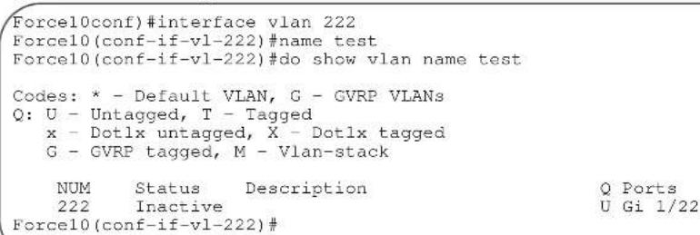
Related Commands
vlan-stack compatible Enable the Stackable VLAN feature on the selected VLAN.
interface vlan Configure a VLAN.
tagged

Add a Layer 2 interface to a VLAN as a tagged interface.
Syntax
tagged interface
To remove a tagged interface from a VLAN, use no tagged interface command.
Parameters
| interface | Enter the following keywords and slot/port or number information:For a 1-Gigabit Ethernet interface, enter the keyword GigabitEthernet followed by the slot/port information.For a Port Channel interface, enter the keyword port-channel followed by a number:C-Series and S-Series Range: 1-128E-Series Range: 1 to 32 for EtherScale, 1 to 255 for TeraScale and 1 to 512 for ExaScale.For a 10-Gigabit Ethernet interface, enter the keyword TenGigabitEthernet followed by the slot/port information. |
Defaults
All interfaces in Layer 2 mode are untagged.
Command Modes
INTERFACE VLAN
Command History
Version 7.6.1.0 Introduced on S-Series
Version 7.5.1.0 Introduced on C-Series
pre-Version 6.1.1.1 Introduced on E-Series
| Usage Information | When you use thenotaggedcommand, the interface is automatically placed in the Default VLAN as an untagged interface unless the interface is a member of another VLAN. If the interface belongs to several VLANs, you must remove it from all VLANs to change it to an untagged interface.Tagged interfaces can belong to multiple VLANs, while untagged interfaces can only belong to one VLAN at a time. | |
| Related Commands | interface vlanConfigure a VLAN. | |
| untaggedSpecify which interfaces in a VLAN are untagged. | ||
| track ipC E S | Track the Layer 3 operational state of a Layer 3 VLAN, using a subset of the VLAN member interfaces. | |
| Syntax | track ipinterfaceTo remove the tracking feature from the VLAN, use thenotrack ipinterfacecommand. | |
| Parameters | interfaceEnter the following keywords and slot/port or number information:For a 1-Gigabit Ethernet interface, enter the keyword followed by the slot/port information.For a Port Channel interface, enter the keyword port-channel followed by a number:C-Series and S-Series Range: 1-128E-Series Range: 1 to 32 for EtherScale, 1 to 255 for TeraScale and 1 to 512 for ExaScale.For a SONET interface, enter the keyword sonet followed by the slot/port information.For a 10-Gigabit Ethernet interface, enter the keyword TenGigabitEthernet followed by the slot/port information. | |
| Defaults | Not configured | |
| Command Modes | INTERFACE VLAN | |
| Command History | Version 7.6.1.0 Introduced on S-Series | |
| Version 7.5.1.0 Introduced on C-Series | ||
| pre-Version 6.2.1.1 Introduced on E-Series | ||
| Usage Information | When this command is configured, the VLAN is operationally UP if any of the interfaces specified in the track ip command are operationally UP, and the VLAN is operationally DOWN if none of the tracking interfaces are operationally UP.If the track ip command is not configured, the VLAN's Layer 3 operational state depends on all the members of the VLAN.The Layer 2 state of the VLAN, and hence the Layer 2 traffic is not affected by the track ip command configuration. | |
Related Commands
interface vlan Configure a VLAN.
tagged Specify which interfaces in a VLAN are tagged.
untagged

Add a Layer 2 interface to a VLAN as an untagged interface.
Syntax
untagged interface
To remove an untagged interface from a VLAN, use the no untagged interface command.
Parameters
interface
Enter the following keywords and slot/port or number information:
- For a 1-Gigabit Ethernet interface, enter the keyword the slot/port information.
GigabitEthernet followed by
- For a Port Channel interface, enter the keyword number:
C-Series and S-Series Range: 1-128
E-Series Range: 1 to 32 for EtherScale, 1 to 255 for TeraScale and 1 to 512 for ExaScale.
- For a 10-Gigabit Ethernet interface, enter the keyword followed by the slot/port information.
TenGigabitEthernet
Defaults
All interfaces in Layer 2 mode are untagged.
Command Modes
INTERFACE VLAN
Command History
Version 7.6.1.0 Introduced on S-Series
Version 7.5.1.0 Introduced on C-Series
pre-Version 6.2.1.1 Introduced on E-Series
Usage Information
Untagged interfaces can only belong to one VLAN.
In the Default VLAN, you cannot use the no untagged interface command. To remove an untagged interface from all VLANs, including the Default VLAN, enter the INTERFACE mode and use the no switchport command.
Related Commands
interface vlan Configure a VLAN.
tagged Specify which interfaces in a VLAN are tagged.
Link Layer Detection Protocol (LLDP)
Overview
Link Layer Detection Protocol (LLDP) advertises connectivity and management from the local station to the adjacent stations on an IEEE 802 LAN. LLDP facilitates multi-vendor interoperability by using standard management tools to discover and make available a physical topology for network management. The FTOS implementation of LLDP is based on IEEE standard 801.1ab.
The basic LLDP commands are supported by FTOS on all Dell Force10 systems, as indicated by the characters that appear below each command heading:
• C-Series: C
• E-Series: E
• S-Series: S
Commands
This chapter contains the following commands, in addition to the commands in the related section — LLDP-MED Commands.
- advertise dot1-tlv
- advertise dot3-tlv
- advertise management
- clear lldp counters
- clear lldp neighbors
- debug lldp interface
- disable
- hello
• mode - multiplier
- protocol lldp (Configuration)
- protocol lldp (Interface)
• show lldp neighbors
• show lldp statistics
• show running-config lldp
The starting point for using LLDP is invoking LLDP with the protocol lldp command in either the CONFIGURATION or INTERFACE mode.
The information distributed by LLDP is stored by its recipients in a standard Management Information Base (MIB). The information can be accessed by a network management system through a management protocol such as SNMP.
See the Link Layer Discovery Protocol chapter of the FTOS Configuration Guide for details on implementing LLDP/LLDP-MED.
advertise dot1-tlv

Advertise dot1 TLVs (Type, Length, Value).
Syntax
advertise dot1-tlv {port-protocol-vlan-id | port-vlan-id | vlan-name}
To remove advertised dot1-tlv, use the no advertise dot1-tlv {port-protocol-vlan-id | port-vlan-id | vlan-name} command.
Parameters
| port-protocol-vlan-id | Enter the keyword port-protocol-vlan-id to advertise the port protocol VLAN identification TLV. |
| port-vlan-id | Enter the keyword port-vlan-id to advertise the port VLAN identification TLV. |
| vlan-name | Enter the keyword vlan-name to advertise the vlan-name TLV. This keyword is only supported on C-Series and S-Series. |
Defaults
Disabled
Command Modes
CONFIGURATION (conf-lldp) and INTERFACE (conf-if-interface-lldp)
Command History
| Version 7.7.1.0 | Introduced on S-Series, addedvlan-nameoption. |
| Version 7.6.1.0 Introduced on C-Series | |
| Version 7.4.1.0 Introduced on E-Series | |
Related Commands
| protocol lldp (Configuration) Enable LLDP globally. |
| debug lldp interface Debug LLDP |
| show lldp neighbors Display the LLDP neighbors |
| show running-config lldp Display the LLDP running configuration |
advertise dot3-tlv

Advertise dot3 TLVs (Type, Length, Value).
Syntax
advertise dot3-tlv {max-frame-size}
To remove advertised dot3-tlv, use the no advertise dot3-tlv {max-frame-size} command.
Parameters
max-frame-size
Enter the keyword max-frame-size to advertise the dot3 maximum frame size.
| Defaults | No default values or behavior |
| Command Modes | CONFIGURATION (conf-lldp) and INTERFACE (conf-if-interface-lldp) |
| Command History | Version 7.7.1.0 Introduced on S-Series |
| Version 7.6.1.0 Introduced on C-Series | |
| Version 7.4.1.0 Introduced on E-Series |
advertise management

Advertise management TLVs (Type, Length, Value).
Syntax advertise management -tlv {system-capabilities | system-description | system-name}
To remove advertised management TLVs, use the no advertise management -tlv {system-capabilities | system-description | system-name} command.
| Parameters | system-capabilities | Enter the keyword system-capabilities to advertise the system capabilities TLVs. |
| system-description | Enter the keyword system-description to advertise the system description TLVs. | |
| system-name | Enter the keyword system-description to advertise the system description TLVs. |
Defaults No default values or behavior
Command Modes CONFIGURATION (conf-lldp)
| Command History | Version 7.7.1.0 Introduced on S-Series |
| Version 7.6.1.0 Introduced on C-Series | |
| Version 7.4.1.0 Introduced on E-Series |
Usage All three command options — system-capabilities, system-description, and system-name} Information —can be invoked individually or together, in any sequence.
clear lldp counters

Clear LLDP transmitting and receiving counters for all physical interfaces or a specific physical interface.
Syntax clear lldp counters interface
| Parameters | interface | Enter the following keywords and slot/port or number information:For a Fast Ethernet interface, enter the keyword slot/port information.For a 1-Gigabit Ethernet interface, enter the keyword by the slot/port information.For a 10-Gigabit Ethernet interface, enter the keyword followed by the slot/port information. | FastEthernetfollowed by the gigabitEthernetfollowed tenGigabitEthernet |
| Defaults | No default values or behavior | ||
| Command Modes | EXEC Privilege | ||
| Command History | Version 7.7.1.0 Introduced on S-Series | ||
| Version 7.6.1.0 Introduced on C-Series | |||
| Version 7.4.1.0 Introduced on E-Series | |||
clear lldp neighbors

Clear LLDP neighbor information for all interfaces or a specific interfaces.
Syntax
clear lldp neighbors {interface}
| Parameters | interface | Enter the following keywords and slot/port or number information:For a Fast Ethernet interface, enter the keyword slot/port information.For a 1-Gigabit Ethernet interface, enter the keyword by the slot/port information.For a 10-Gigabit Ethernet interface, enter the keyword followed by the slot/port information. | FastEthernetfollowed by the gigabitEthernetfollowed tenGigabitEthernet |
| Defaults | No default values or behavior | ||
| mand Modes | EXEC Privilege | ||
| Command History | Version 7.7.1.0 Introduced on S-Series | ||
| Version 7.6.1.0 Introduced on C-Series | |||
| Version 7.4.1.0 Introduced on E-Series | |||
debug lldp interface

Enable LLDP debugging to display timer events, neighbor additions or deletions, and other information about incoming and outgoing packets.
Syntax
debug lldp interface {interface | all} {events| packet {brief | detail} {tx | rx | both}}
To disable debugging, use the no debug lldp interface {interface | all} {events} {packet {brief | detail} {tx | rx | both}} command.
| Parameters | interface | Enter the following keywords and slot/port or number information:For a Fast Ethernet interface, enter the keywordFastEthernetfollowed by the slot/port information.For a 1-Gigabit Ethernet interface, enter the keyword followed by the slot/port information.For a 10-Gigabit Ethernet interface, enter the keyword followed by the slot/port information.Note:The FastEthernetoption is not supported on S-Series. |
| all | (OPTIONAL) Enter the keyword all to display information on all interfaces. | |
| events | (OPTIONAL) Enter the keyword events to display major events such as timer events. | |
| packet | (OPTIONAL) Enter the keyword packet to display information regarding packets coming in or going out. | |
| brief | (OPTIONAL) Enter the keyword brief to display brief packet information. | |
| detail | (OPTIONAL) Enter the keyword detail to display detailed packet information. | |
| tx | (OPTIONAL) Enter the keyword tx to display transmit only packet information. | |
| rx | (OPTIONAL) Enter the keyword rx to display receive only packet information | |
| both | (OPTIONAL) Enter the keyword both to display both receive and transmit packet information. |
| Defaults | No default values or behavior |
| Command Modes | EXEC Privilege |
| Command History | Version 7.7.1.0 Introduced on S-Series |
| Version 7.6.1.0 Introduced on C-Series | |
| Version 7.4.1.0 Introduced on E-Series |
disable

Enable or disable LLDP.
Syntax disable
To enable LLDP, use the no disable
Defaults Enabled, that is no disable
Command Modes CONFIGURATION (conf-lldp) and INTERFACE (conf-if-interface-lldp)
| Command History | Version 7.7.1.0 Introduced on S-Series |
| Version 7.6.1.0 Introduced on C-Series | |
| Version 7.4.1.0 Introduced on E-Series |
| Related Commands | protocol lldp (Configuration) Enable LLDP globally. |
| debug lldp interface Debug LLDP |
hello
C E S
Syntax
Configure the rate at which the LLDP control packets are sent to its peer.
hello seconds
To revert to the default, use the no hello seconds command.
Parameters
| seconds | Enter the rate, in seconds, at which the control packets are sent to its peer. Rate: 5 - 180 seconds Default: 30 seconds |
Defaults
30 seconds
Command Modes
CONFIGURATION (conf-lldp) and INTERFACE (conf-if-interface-lldp)
Command History
| Version 7.7.1.0 Introduced on S-Series |
| Version 7.6.1.0 Introduced on C-Series |
| Version 7.4.1.0 Introduced on E-Series |
mode
C E S
Set LLDP to receive or transmit.
Syntax
mode {tx | rx}
To return to the default, use the no mode {tx | rx} command.
Parameters
tx Enter the keyword tx to set the mode to transmit.
rx Enter the keyword rx to set the mode to receive.
Defaults
Both transmit and receive
Command Modes
CONFIGURATION (conf-lldp) and INTERFACE (conf-if-interface-lldp)
Command History
| Version 7.7.1.0 Introduced on S-Series |
| Version 7.6.1.0 Introduced on C-Series |
| Version 7.4.1.0 Introduced on E-Series |
Related Commands
| protocol lldp (Configuration) Enable LLDP globally. |
| show lldp neighbors Display the LLDP neighbors |
multiplier
| C | E | S |
Set the number of consecutive misses before LLDP declares the interface dead.
Syntax
multiplier integer
To return to the default, use the no multiplier integer command.
| Parameters | integer | Enter the number of consecutive misses before the LLDP declares the interface dead. Range: 2 - 10 |
| Defaults | 4 x hello | |
| hand Modes | CONFIGURATION (conf-lldp) and INTERFACE (conf-if-interface-lldp) | |
| Command History | Version 7.7.1.0 Introduced on S-Series | |
| Version 7.6.1.0 Introduced on C-Series | ||
| Version 7.4.1.0 Introduced on E-Series | ||
protocol lldp (Configuration)
| C | E | S |
Enable LLDP globally on the switch.
Syntax
protocol lldp
To disable LLDP globally on the chassis, use the no protocol lldp command.
Defaults
Disabled
| Command Modes | CONFIGURATION (conf-lldp) |
| Command History | Version 7.7.1.0 Introduced on S-Series |
| Version 7.6.1.0 Introduced on C-Series | |
| Version 7.4.1.0 Introduced on E-Series |
protocol lldp (Interface)
| C | E | S |
Enter the LLDP protocol in the INTERFACE mode.
Syntax
[no] protocol lldp
To return to the global LLDP configuration mode, use the no protocol lldp command from the Interface mode.
Defaults
LLDP is not enabled on the interface.
| Command Modes | INTERFACE (conf-if-interface-lldp) | |
| Command History | Version 7.7.1.0 Introduced on S-Series | |
| Version 7.6.1.0 Introduced on C-Series | ||
| Version 7.4.1.0 Introduced on E-Series | ||
| Usage Information | LLDP must be enabled globally from CONFIGURATION mode, before it can be configured on an interface. This command places you in LLDP mode on the interface; it does not enable the protocol.When you enter the LLDP protocol in the Interface context, it overrides global configurations. When you execute theno protocol lldpfrom the INTERFACE mode, interfaces will begin to inherit the configuration from the global LLDP CONFIGURATION mode. | |
| show lldp neighborsC E S Display LLDP neighbor information for all interfaces or a specified interface. | ||
| Syntax | show lldp neighbors [interface] [detail] | |
| Parameters | interface (OPTIONAL) Enter the following keywords and slot/port or number information:For a Fast Ethernet interface, enter the keywordFastEthernetfollowed by the slot/port information.For a 1-Gigabit Ethernet interface, enter the keyword gigabitEthernetfollowed by the slot/port information.For a 10-Gigabit Ethernet interface, enter the keyword tenGigabitEthernetfollowed by the slot/port information. | |
| detail (OPTIONAL) Enter the keyword detailto display all the TLV information, timers, and LLDP tx and rx counters. | ||
| Defaults | No default values or behavior | |
| Command Modes | EXEC Privilege | |
| Command History | Version 7.7.1.0 Introduced on S-Series | |
| Version 7.6.1.0 Introduced on C-Series | ||
| Version 7.4.1.0 Introduced on E-Series | ||
| Example | Figure 32-1. show lldp neighbors Command Output | |
| R1 (conf-if-gi-1/31)#do show lldp neighborsLoc PortID Rem Host Name Rem Port Id Rem Chassis IdGi 1/21 R2 GigabitEthernet 2/11 00:01:e8:06:95:3eGi 1/31 R3 GigabitEthernet 3/11 00:01:e8:09:c2:4a | ||
| Usage Information | Omitting the keyword detail displays only the remote chassis ID, Port ID, and Dead Interval. | |
show lldp statistics

Display the LLDP statistical information.
Syntax
show lldp statistics
Defaults
No default values or behavior
Command Modes
EXEC Privilege
Command History
Version 7.7.1.0 Introduced on S-Series
Version 7.6.1.0 Introduced on C-Series
Version 7.4.1.0 Introduced on E-Series
Example
Figure 32-2. show lldp statistics Command Output
Forcel0#show lldp statistics
Total number of neighbors: 300
Last table change time : Mon Oct 02 16:00:52 2006
Number of Table Inserts : 1621
Number of Table Deletes : 200
Number of Table Drops : 0
Number of Table Age Outs : 400
Forcel0#
show running-config lldp

Display the current global LLDP configuration.
Syntax
show running-config lldp
Defaults
No default values or behavior
Command Modes
EXEC Privilege
Command History
Version 7.7.1.0 Introduced on S-Series
Version 7.6.1.0 Introduced on C-Series
Version 7.4.1.0 Introduced on E-Series
Example
Force10#show running-config lldp
!
protocol lldp
advertise dot1-tlv port-protocol-vlan-id port-vlan-id
advertise dot3-tlv max-frame-size
advertise management-tlv system-capabilities system-description
hello 15
multiplier 3
no disable
Force10#
LLDP-MED Commands
The LLDP-MED commands in this section are:
FTOS LLDP-MED (Media Endpoint Discovery) commands are an extension of the set of LLDP TLV advertisement commands. The C-Series and S-Series support all commands, as indicated by these symbols underneath the command headings: C S
The E-Series generally supports the commands, too, as indicated by the symbol under command headings. However, LLDP-MED commands are more useful on the C-Series and the S50V model of the S-Series, because they support Power over Ethernet (PoE) devices.
As defined by ANSI/TIA-1057, LLDP-MED provides organizationally specific TLVs (Type Length Value), so that endpoint devices and network connectivity devices can advertise their characteristics and configuration information. The Organizational Unique Identifier (OUI) for the Telecommunications Industry Association (TIA) is 00-12-BB.
- LLDP-MED Endpoint Device—any device that is on an IEEE 802 LAN network edge, can communicate using IP, and uses the LLDP-MED framework.
- LLDP-MED Network Connectivity Device—any device that provides access to an IEEE 802 LAN to an LLDP-MED endpoint device, and supports IEEE 802.1AB (LLDP) and TIA-1057 (LLDP-MED). The Dell Force10 system is an LLDP-MED network connectivity device.
With regard to connected endpoint devices, LLDP-MED provides network connectivity devices with the ability to:
- manage inventory
- manage Power over Ethernet (POE)
- identify physical location
- identify network policy
Configure the system to advertise a separate limited voice service for a guest user with their own IP telephony handset or other appliances that support interactive voice services.
Syntax
advertise med guest-voice {vlan-id layer2_priority DSCP_value} | {priority-tagged number}
To return to the default, use the no advertise med guest-voice {vlan-id layer2_priority DSCP_value} | {priority-tagged number} command.
Parameters
| vlan-id | Enter the VLAN ID. Range: 1 to 4094 |
| layer2_priority | Enter the Layer 2 priority. Range: 0 to 7 |
| DSCP_value | Enter the DSCP value. Range: 0 to 63 |
| priority-tagged number | Enter the keyword priority-tagged followed the Layer 2 priority. Range: 0 to 7 |
Defaults
unconfigured
Command Modes
CONFIGURATION (conf-lldp)
Command History
| Version 7.7.1.0 Introduced on S-Series |
| Version 7.6.1.0 Introduced on C-Series and E-Series |
Related Commands
| protocol lldp (Configuration) Enable LLDP globally. |
| debug lldp interface Debug LLDP. |
| show lldp neighbors Display the LLDP neighbors. |
| show running-config lldp Display the LLDP running configuration. |
Configure the system to advertise a separate limited voice service for a guest user when the guest voice control packets use a separate network policy than the voice data.
Syntax
advertise med guest-voice-signaling {vlan-id layer2_priority DSCP_value} | {priority-tagged number}
To return to the default, use the no advertise med guest-voice-signaling {vlan-id layer2_priority DSCP_value} | {priority-tagged number} command.
Parameters
| vlan-id | Enter the VLAN ID. Range: 1 to 4094 |
| layer2_priority | Enter the Layer 2 priority. Range: 0 to 7 |
| DSCP_value | Enter the DSCP value.Range: 0 to 63 | |
| priority-tagged number | Enter the keyword priority-tagged followed the Layer 2 priority.Range: 0 to 7 | |
| Defaults | unconfigured | |
| Command Modes | CONFIGURATION (conf-lldp) | |
| Command History | Version 7.7.1.0 Introduced on S-Series | |
| Version 7.6.1.0 Introduced on C-Series and E-Series | ||
| Related Commands | debug lldp interface Debug LLDP | |
| show lldp neighbors Display the LLDP neighbors | ||
| show running-config lldp Display the LLDP running configuration | ||
advertise med location-identification

Configure the system to advertise a location identifier.
Syntax
advertise med location-identification {coordinate-based value | civic-based value |ecs-elin value}
To return to the default, use the no advertise med location-identification {coordinate-based value | civic-based value | ecs-elin value} command.
Parameters
| coordinate-based value | Enter the keyword coordinate-based followed by the coordinated based location in hexadecimal value of 16 bytes. |
| civic-based value | Enter the keyword civic-based followed by the civic based location in hexadecimal format.Range: 6 to 255 bytes |
| ecs-elin value | Enter the keywordecs-elin followed by the Emergency Call Service (ecs) Emergency Location Identification Number (elin) numeric location string.Range: 10 to 25 characters |
Defaults
unconfigured
Command Modes
CONFIGURATION (conf-lldp)
Command History
Version 7.7.1.0 Introduced on S-Series
Version 7.6.1.0 Introduced on C-Series and E-Series
Usage Information
ECS—Emergency Call Service such as defined by TIA or National Emergency Numbering Association (NENA)
ELIN—Emergency Location Identification Number, a valid North America Numbering Plan format telephone number supplied for ECS purposes.
| Related Commands | debug lldp interface Debug LLDP |
| show lldp neighbors Display the LLDP neighbors | |
| show running-config lldp Display the LLDP running configuration |
C S Configure the system to advertise the Extended Power via MDI TLV.
Defaults unconfigured
Command Modes CONFIGURATION (conf-lldp)
| Command History | Version 7.7.1.0 Introduced on S-Series |
Usage Information Advertise the Extended Power via MDI on all ports that are connected to an 802.3af powered, LLDP-MED endpoint device.
| Related Commands | debug lldp interface Debug LLDP |
| show lldp neighbors Display the LLDP neighbors | |
| show running-config lldp Display the LLDP running configuration |
C E S Configure the system to advertise softphone to enable IP telephony on a computer so that the computer can be used as a phone.
Syntax advertise med softphone-voice {vlan-id layer2_priority DSCP_value} | {priority-tagged number}
To return to the default, use the no advertise med softphone-voice {vlan-id layer2_priority DSCP_value} | {priority-tagged number} command.
| Parameters | vlan-id | Enter the VLAN ID. Range: 1 to 4094 |
| layer2_priority | Enter the Layer 2 priority (C-Series and E-Series only). Range: 0 to 7 | |
| DSCP_value | Enter the DSCP value (C-Series and E-Series only). Range: 0 to 63 | |
| priority-tagged number | Enter the keyword priority-tagged followed the Layer 2 priority. Range: 0 to 7 |
Defaults unconfigured
Command Modes CONFIGURATION (conf-lldp)
| Command History | Version 7.7.1.0 Introduced on S-Series |
| Version 7.6.1.0 Introduced on C-Series and E-Series | |
| Related Commands | debug lldp interface Debug LLDP |
| show lldp neighbors Display the LLDP neighbors | |
| show lldp neighbors Display the LLDP running configuration |
Configure the system to advertise streaming video services for broadcast or multicast-based video. This does not include video applications that rely on TCP buffering.
Syntax advertise med streaming-video {vlan-id layer2_priority DSCP_value} | {priority-tagged number}
To return to the default, use the no advertise med streaming-video {vlan-id layer2_priority DSCP_value} | {priority-tagged number} command.
| Parameters | vlan-id | Enter the VLAN ID. Range: 1 to 4094 |
| layer2_priority | Enter the Layer 2 priority (C-Series and E-Series only). Range: 0 to 7 | |
| DSCP_value | Enter the DSCP value (C-Series and E-Series only). Range: 0 to 63 | |
| priority-tagged number | Enter the keyword priority-tagged followed the Layer 2 priority. Range: 0 to 7 |
Defaults unconfigured
Command Modes CONFIGURATION (conf-lldp)
| Command History | Version 7.7.1.0 Introduced on S-Series |
| Version 7.6.1.0 Introduced on C-Series and E-Series | |
| Related Commands | debug lldp interface Debug LLDP |
| show lldp neighbors Display the LLDP neighbors | |
| show lldp neighbors Display the LLDP running configuration |
advertise med video-conferencing

Configure the system to advertise dedicated video conferencing and other similar appliances that support real-time interactive video.
Syntax
advertise med video-conferencing { vlan-id layer2_priority DSCP_value} | {priority-tagged number}
To return to the default, use the no advertise med video-conferencing {vlan-id layer2_priority DSCP_value} | {priority-tagged number} command.
Parameters
| vlan-id | Enter the VLAN ID. Range: 1 to 4094 |
| layer2_priority | Enter the Layer 2 priority (C-Series and E-Series only). Range: 0 to 7 |
| DSCP_value | Enter the DSCP value (C-Series and E-Series only). Range: 0 to 63 |
| priority-tagged number | Enter the keyword priority-tagged followed the Layer 2 priority. Range: 0 to 7 |
Defaults
unconfigured
Command Modes
CONFIGURATION (conf-lldp)
Command History
| Version 7.7.1.0 Introduced on S-Series |
| Version 7.6.1.0 Introduced on C-Series and E-Series |
Related Commands
| debug lldp interface Debug LLDP |
| show lldp neighbors Display the LLDP neighbors |
| show running-config lldp Display the LLDP running configuration |
Configure the system to advertise video control packets that use a separate network policy than video data.
Syntax
advertise med video-signaling {vlan-id layer2_priority DSCP_value} | {priority-tagged number}
To return to the default, use the no advertise med video-signaling {vlan-id layer2_priority DSCP_value} | {priority-tagged number} command.
Parameters
| vlan-id | Enter the VLAN ID. Range: 1 to 4094 |
| layer2_priority | Enter the Layer 2 priority (C-Series and E-Series only). Range: 0 to 7 |
| DSCP_value | Enter the DSCP value (C-Series and E-Series only).Range: 0 to 63 | |
| priority-tagged number | Enter the keyword priority-tagged followed the Layer 2 priority.Range: 0 to 7 | |
| Defaults | unconfigured | |
| Command Modes | CONFIGURATION (conf-lldp) | |
| Command History | Version 7.7.1.0 Introduced on S-Series | |
| Version 7.6.1.0 Introduced on C-Series and E-Series | ||
| Related Commands | debug lldp interface Debug LLDP | |
| show lldp neighbors Display the LLDP neighbors | ||
| show lldp neighbors Display the LLDP running configuration | ||
advertise med voice

Configure the system to advertise a dedicated IP telephony handset or other appliances supporting interactive voice services.
Syntax
advertise med voice {vlan-id layer2_priority DSCP_value} | {priority-tagged number}
To return to the default, use the no advertise med voice {vlan-id layer2_priority DSCP_value} | {priority-tagged number} command.
Parameters
| vlan-id | Enter the VLAN ID. Range: 1 to 4094 |
| layer2_priority | Enter the Layer 2 priority (C-Series and E-Series only). Range: 0 to 7 |
| DSCP_value | Enter the DSCP value (C-Series and E-Series only). Range: 0 to 63 |
| priority-tagged number | Enter the keyword priority-tagged followed the Layer 2 priority. Range: 0 to 7 |
Defaults
unconfigured
Command Modes
CONFIGURATION (conf-lldp)
Command
Version 7.7.1.0 Introduced on S-Series
History
Version 7.6.1.0 Introduced on C-Series and E-Series
Related
Commands
debug lldp interface Debug LLDP
show lldp neighbors Display the LLDP neighbors
show running-config lldp Display the LLDP running configuration
Configure the system to advertise when voice control packets use a separate network policy than voice data.
Syntax
advertise med voice-signaling {vlan-id layer2_priority DSCP_value} | {priority-tagged number}
To return to the default, use the no advertise med voice-signaling {vlan-id layer2_priority DSCP_value} | {priority-tagged number} command.
Parameters
| vlan-id | Enter the VLAN ID. Range: 1 to 4094 |
| layer2_priority | Enter the Layer 2 priority (C-Series and E-Series only). Range: 0 to 7 |
| DSCP_value | Enter the DSCP value (C-Series and E-Series only). Range: 0 to 63 |
| priority-tagged number | Enter the keyword priority-tagged followed the Layer 2 priority. Range: 0 to 7 |
Defaults
unconfigured
Command Modes
CONFIGURATION (conf-lldp)
Command History
Version 7.7.1.0 Introduced on S-Series
Version 7.6.1.0 Introduced on C-Series and E-Series
Related Commands
debug lldp interface Debug LLDP
show lldp neighbors Display the LLDP neighbors
show lldp neighbors Display the LLDP running configuration
Multicast Listener Discovery (MLD)
Overview
The platforms on which a command is supported is indicated by the character — E for the E-Series, C for the C-Series, and S for the S-Series — that appears below each command heading.
This chapter contains the following sections:
- MLD Commands
- MLD Snooping Commands
MLD Commands
The MLD commands are:
- clear ipv6 mld groups
- debug ipv6 mld
- ipv6 mld explicit-tracking
- ipv6 mld last-member-query-interval
- ipv6 mld querier-timeout
- ipv6 mld query-interval
- ipv6 mld query-max-resp-time
- ipv6 mld static-group
- ipv6 mld version
• show ipv6 mld interface
clear ipv6 mld groups

Clear entries from the group cache table.
Syntax
clear ipv6 mld groups [interface | group-address]
| Parameters | interface | (OPTIONAL) Enter the following keywords and slot/port or number information:For a 1-Gigabit Ethernet interface, enter the keywordGigabitEthernet followed by the slot/port information.For a Port Channel interface, enter the keywordport-channelfollowed by a number:E-SeriesRange: 1 to 32 for EtherScale, 1 to 255 for TeraScale and 1 to 512 for ExaScale.For a SONET interface, enter the keywordsonetfollowed by the slot/port information.For a 10-Gigabit Ethernet interface, enter the keywordTenGigabitEthernetfollowed by the slot/port information.For a VLAN, enter the keywordvlanfollowed by a number from 1 to 4094. |
| group-address | (OPTIONAL) Enter the group address in the X:X:X:X::X format.The :: notation specifies successive hexadecimal fields of zero. | |
| Defaults | No default values or behavior | |
| Command Modes | EXEC Privilege | |
| Command History | Version 7.4.1.0 Introduced | |
| Related Commands | show ipv6 mld interface Display the IPv6 MLD interface | |
debug ipv6 mld

Enable debugging on IPv6 MLD packets.
Syntax
debug ipv6 mld {group-address | interface}
To turn off debugging, use the no debug ipv6 mld {group-address | interface} command.
Parameters
| group-address | (OPTIONAL) Enter the multicast group address in the X:X:X:X::X format.The :: notation specifies successive hexadecimal fields of zero. |
| interface | (OPTIONAL) Enter the following keywords and slot/port or number information:For a 1-Gigabit Ethernet interface, enter the keyword GigabitEthernet followed by the slot/port information.For a Port Channel interface, enter the keyword port-channel followed by a number:E-Series Range: 1 to 32 for EtherScale, 1 to 255 for TeraScale and 1 to 512 for ExaScale.For a SONET interface, enter the keyword sonet followed by the slot/port information.For a 10-Gigabit Ethernet interface, enter the keyword TenGigabitEthernet followed by the slot/port information.For a VLAN, enter the keyword vlan followed by a number from 1 to 4094. |
Defaults
Disabled
Command Modes
EXEC Privilege
Command History
Version 7.4.1.0 Introduced
ipv6 mld explicit-tracking

Enable MLD explicit tracking of receivers.
Syntax
ipv6 mld explicit-tracking
To disable explicit tracking, use the no ipv6 mld explicit-tracking command.
Defaults
Disabled
Command Modes
INTERFACE (conf-if)
Command History
Version 7.4.1.0 Introduced
Usage Information
If snooping is enabled on the VLAN, this command has no effect. Enable ipv6 mld snooping explicit tracking instead.
ipv6 mld last-member-query-interval

Change the MAX Response Time inserted into the Group-Specific Queries sent in response to a Leave Group messages. This interval is also the interval between Group-Specific Query messages.
Syntax
ipv6 mld last-member-query-interval { milliseconds}
To return to the default, use the no ipv6 mld last-member-query-interval {milliseconds} command.
Parameters
milliseconds
Enter the last member query interval in milliseconds.
Range: 200 - 60000
Default: 1000
Defaults
1000 milliseconds
Command Modes
INTERFACE (conf-if)
Command History
Version 7.4.1.0 Introduced
ipv6 mld querier-timeout

Change the interval that must pass before a multicast router decides that there is no longer another multicast router that should be the querier.
Syntax
ipv6 mld querier-timeout {seconds}
To return to the default, use the no ipv6 mld querier-timeout command.
| Parameters | seconds | Enter the querier timeout in seconds. Range: 60 - 300 Default: 255 |
| Defaults | 255 seconds | |
| Command Modes | INTERFACE (conf-if) | |
| Command History | Version 7.4.1.0 Introduced | |
ipv6 mld query-interval
Change the transmission frequency of the MLD host.
Syntax ipv6 mld query-interval {seconds}
To return to the default interval, use the no ipv6 mld query-interval command.
| Parameters | seconds | Enter the interval in seconds. Range: 1 - 18000 Default: 125 |
Defaults 125 seconds
Command Modes INTERFACE (conf-if)
Command History Version 7.4.1.0 Introduced
ipv6 mld query-max-resp-time
Set the maximum query response time advertised in the general queries.
Syntax ipv6 mld query-max-resp-time {seconds}
To return to the default, use the no ipv6 mld query-max-resp-time command.
| Parameters | seconds | Enter the interval in seconds. |
| Range: 1 - 25 | ||
| Default: 10 |
Defaults 10 seconds
Command Modes INTERFACE (conf-if)
Command History Version 7.4.1.0 Introduced
ipv6 mld static-group
E Configure an MLD static group to exclude or include mode.
Syntax ipv6 mld static-group group-address {exclude [source-address] | include source-address} To return to default, use the no ipv6 mld static-group group-address {exclude [source-address] | include source-address} command.
| Parameters | group-address | (OPTIONAL) Enter the multicast group address in the X:X:X:X::X format.The :: notation specifies successive hexadecimal fields of zero. |
| exclude source-address | Enter the keyword exclude and optionally enter the source ip address in the X:X:X:X::X format.The :: notation specifies successive hexadecimal fields of zero. | |
| include source-address | Enter the keyword include followed by source ip address in the X:X:X:X::X format.The :: notation specifies successive hexadecimal fields of zero. |
Defaults No default behavior or values
Command Modes INTERFACE (conf-if)
Command History Version 7.4.1.0 Introduced
ipv6 mld version
E Set the MLD version number on this interface.
Syntax ipv6 mld version 1
Defaults Version 2
Command Modes INTERFACE (conf-if)
Command History Version 7.4.1.0 Introduced
Usage FTOS supports MLD version 2 and is backward compatible with MLD version 1.
Command History Version 7.4.1.0 Introduced
show ipv6 mld groups
E View the configured MDL groups.
Syntax show ipv6 mld groups [detail] [explicit] [link-local] [group-address] [interface interface [detail]] [summary]
Parameters
| explicit Enter this keyword to display explicit tracking information. | |
| link-local Enter this keyword to display link-local groups. | |
| group-address Enter the group address for which you want to display information. | |
| interface interface Enter the keyword interface followed by the interface type. | |
| detail View detailed group information. | |
| summary View a summary of group information. |
Command Modes
EXEC
EXEC Privilege
Command History
Version 7.4.1.0 Introduced
Example
Figure 33-1. show ipv6 mld groups Command Example
| Force10#show ipv6 mld groups vlan 100 link-local ? | ||
| detail | Detailed information | |
| | | Pipe through a command | |
| show ipv6 mld groups explicit | ||
| Interface GigabitEthernet 2/14, Group ff02::1:ff00:0 | ||
| Reporter fe80::200:ff:fe00:0 | ||
| Uptime 00:00:19, Expires in 00:04:00 | ||
| Mode EXCLUDE | ||
| Interface GigabitEthernet 2/14, Group ff02::1:ff00:5 | ||
| Reporter fe80::200:ff:fe00:0 | ||
| Uptime 00:00:19, Expires in 00:04:00 | ||
| Mode EXCLUDE | ||
| Interface GigabitEthernet 2/14, Group ff3e:100::4000:1 | ||
| Reporter fe80::200:ff:fe00:0 | ||
| Uptime 00:00:16, Expires in 00:04:03 | ||
| Mode INCLUDE | ||
| 165:87:32::8 | ||
| 165:87:32::9 | ||
| 165:87:32::a | ||
| Interface GigabitEthernet 2/14, Group ff3e:100::4000:2 | ||
| Reporter fe80::200:ff:fe00:0 | ||
| Uptime 00:00:16, Expires in 00:04:03 | ||
| Mode INCLUDE | ||
| 165:87:32::8 | ||
| 165:87:32::9 | ||
| 165:87:32::a | ||
| [output omitted] | ||
show ipv6 mld interface

View the configured MDL interfaces.
Syntax
show ipv6 mld interface [interface]
Parameters
| interface[interface] | Enter the keywordinterfaceto display the configured MDL interfaces. Optionally, enter the keywordinterfacefollowed by one of the keywords below, with slot/port or number information, to display information for that specific interface:For a 1-Gigabit Ethernet interface, enter the keywordGigabitEthernetfollowed by the slot/port information.For a Port Channel interface, enter the keywordport-channelfollowed by a number:E-Series Range: 1 to 32 for EtherScale, 1 to 255 for TeraScale and 1 to 512 for ExaScale.For a SONET interface, enter the keywordsonetfollowed by the slot/port information.For a 10-Gigabit Ethernet interface, enter the keywordTenGigabitEthernet followed by the slot/port information.For a VLAN, enter the keywordvlanfollowed by a number from 1 to 4094. |
Command Modes
EXEC
EXEC Privilege
Command History
Version 7.4.1.0 Introduced
Example
Figure 33-2. show ipv6 mld interface Command Example
| Force10#show ipv6 mld interface |
| GigabitEthernet 2/14 is up, line protocol is up Interface address is fe80::201:e8ff:fe08:9a09/64 Current MLD version is 2 MLD query interval is 125 seconds MLD querier expiry time is 255 seconds MLD max query response time is 10 seconds Last member response interval is 1000 ms MLD explicit tracking is disabled MLD querying router is fe80::201:e8ff:fe08:9a09 (this router) |
| Port-channel 200 is up, line protocol is up Interface address is fe80::201:e8ff:fe08:9abd/64 Current MLD version is 2 MLD query interval is 125 seconds MLD querier expiry time is 255 seconds MLD max query response time is 10 seconds Last member response interval is 1000 ms MLD explicit tracking is disabled MLD querying router is fe80::201:e8ff:fe08:9abd (this router) |
| Vlan 200 is up, line protocol is up Interface address is fe80::201:e8ff:fe08:9abc/64 Current MLD version is 2 MLD query interval is 125 seconds MLD querier expiry time is 255 seconds MLD max query response time is 10 seconds Last member response interval is 1000 ms MLD explicit tracking is disabled MLD querying router is fe80::201:e8ff:fe08:9abc (this router) |
| Force10# |
MLD Snooping Commands
The MLD Snooping commands are:
- ipv6 mld snooping enable
- ipv6 mld snooping flood
- ipv6 mld snooping
- ipv6 mld snooping explicit-tracking
- ipv6 mld snooping mrouter
- ipv6 mld snooping querier
• show ipv6 mld snooping groups
• show ipv6 mld snooping mrouter
ipv6 mld snooping enable

Enable MLD Snooping globally.
Syntax
ipv6 mld snooping enable
Defaults
Disabled
Command Modes
Enable MLD Snooping Flood globally.
Syntax
ipv6 mld snooping flood
To disable, use the no ipv6 mld snooping flood command.
Defaults
Enabled
Command Modes
When flooding is enabled, unregistered multicast data is flooded on the VLAN.
When flooding is disabled, unregistered multicast data is forwarded only to mrouter ports on the VLAN.
Command History
Version 7.4.1.0 Introduced
ipv6 mld snooping
E Enable MLD Snooping (v1 and v2) on a VLAN.
Syntax ipv6 mld snooping
To disable MLD Snooping, use the no ipv6 mld snooping command.
Defaults Enabled on all VLAN interfaces
Command Modes INTERFACE VLAN (conf-if-vl-n)
Command History Version 7.4.1.0 Introduced
ipv6 mld snooping explicit-tracking
E Enable explicit MLD Snooping tracking on an interface.
Syntax ipv6 mld snooping explicit-tracking
To disable, use the no ipv6 mld snooping explicit-tracking command.
Defaults Disabled
Command Modes INTERFACE VLAN (conf-if-vl-n)
Command History Version 7.4.1.0 Introduced
Usage Whether the switch is the Querier or not, if snooping is enabled, the switch tracks all MLD joins. It has separate explicit tracking table which contains group, source, interface, VLAN and reporter details.
Related Commands show ipv6 mld snooping groups
ipv6 mld snooping mrouter
E Configure a Layer 2 port as a multicast router port.
Syntax ipv6 mld snooping mrouter interface {interface}
| Parameters | interface | Enter the keywordinterfaceto indicate the next-hop interface to the multicast router. |
| interface | Enter the following keywords and slot/port or number information:For a 1-Gigabit Ethernet interface, enter the keywordGigabitEthernetfollowed by the slot/port information.For a Port Channel interface, enter the keywordport-channelfollowed by a number:E-Series Range: 1 to 32 for EtherScale, 1 to 255 for TeraScale and 1 to 512 for ExaScale.For a 10-Gigabit Ethernet interface, enter the keywordTenGigabitEthernetfollowed by the slot/port information. |
Defaults No default values or behavior
Command Modes INTERFACE VLAN (conf-if-vl-n)
Command History
Version 7.4.1.0 Introduced
ipv6 mld snooping querier
E Enable the MLD querier processing for the VLAN interface.
Syntax ipv6 mld snooping querier
To disable the querier feature, use the no ipv6 mld snooping querier command.
Defaults Disabled
Command Modes INTERFACE VLAN (conf-if-vl-n)
Command History
Version 7.4.1.0 Introduced
Usage Information
This command enables the VLAN to send out periodic queries as a proxy querier. You must configure and IP address for the VLAN.
show ipv6 mld snooping groups
E Display the IPv6 MLD Snooping group information.
Syntax show ipv6 mld snooping groups [group-address] [explicit] [link-local] [summary] [vlan]
| Parameters | group-address | (OPTIONAL) Enter the multicast group address in the X:X:X:X::X format. The :: notation specifies successive hexadecimal fields of zero. |
| explicit | (OPTIONAL) Enter the keyword explicit to display explicit tracking information. | |
| link-local | (OPTIONAL) Enter the keyword link-local to display link local groups. | |
| summary | (OPTIONAL) Enter the keyword summary to display a summary of groups. | |
| vlan | (OPTIONAL) Enter the keyword vlan followed by the VLAN number to display information on that specific VLAN. Range: 1 - 4094 | |
| Defaults | No default values or behavior | |
| mand Modes | EXEC | |
| EXEC Privilege | ||
| Command History | Version 7.4.1.0 Introduced | |
Example
Figure 33-3. show ipv6 mld snooping groups summary Command Example
Force10#show ipv6 mld snooping groups summary
MLD snooping connected groups summary:
(*,G) routes :12
Force10#
show ipv6 mld snooping mrouter

Display information on the MLD Snooping router.
Syntax
show ipv6 mld snooping mrouter [vlan]
Parameters
vlan (OPTIONAL) Enter the keyword vlan followed by the VLAN number to display information on that specific VLAN.
Range: 1 - 4094
Defaults
No default values or behavior
Command Modes
EXEC
EXEC Privilege
Command History
Version 7.4.1.0 Introduced
Example
Figure 33-4. show ipv6 mld snooping mrouter Command Example
Force10#show ipv6 mld snooping mrouter
Interface    Ports (* - Dynamic)
Vlan 2    Gi 13/18
Force10#
Multicast Source Discovery Protocol (MSDP)
Overview
MSDP (Multicast Source Discovery Protocol) connects multiple PIM Sparse-Mode (PIM-SM) domains together. MSDP peers connect using TCP port 639. Peers send keepalives every 60 seconds. A peer connection is reset after 75 seconds if no MSDP packets are received. MSDP connections are parallel with MBGP connections. FTOS supports MSDP commands on the E-Series only, as indicated by the E character that appears below each command heading.
Commands
The commands are:
- clear ip msdp peer
- clear ip msdp sa-cache
- debug ip msdp
- ip msdp cache-rejected-sa
- ip msdp default-peer
- ip msdp log-adjacency-changes
- ip msdp mesh-group
- ip msdp originator-id
- ip msdp peer
- ip msdp redistribute
- ip msdp sa-filter
- ip msdp sa-limit
- ip msdp shutdown
- ip multicast-msdp
• show ip msdp
• show ip msdp sa-cache rejected-sa
clear ip msdp peer
E Reset the TCP connection to the peer and clear all the peer statistics.
Syntax clear ip msdp peer {peer address}
Parameters
peer address
Enter the peer address in a dotted decimal format (A.B.C.D.)
Defaults Not configured
Command Modes EXEC Privilege
| Command History | Version 6.2.1.1 Introduced |
clear ip msdp sa-cache
E Clears the entire source-active cache, the source-active entries of a particular multicast group, rejected, or local source-active entries.
Syntax clear ip msdp sa-cache [group-address | rejected-sa | local]
| Parameters | group-address | Enter the group IP address in dotted decimal format (A.B.C.D.) |
| rejected-sa | Enter this keyword to clear the cache source-active entries that are rejected because the RPF check failed, an SA filter or limit is configured, the RP or MSDP peer is unreachable, or because of a format error. | |
| local | Enter this keyword to clear out local PIM advertised entries. It applies the redistribute filter (if present) while adding the local PIM SA entries to the SA cache. |
Defaults Without any options, this command clears the entire source-active cache.
Command Modes EXEC Privilege
| Command History | Version 7.8.1.0 | Added local option. |
| Version 7.7.1.0 | Added rejected-sa option. | |
| Version 6.2.1.1 Introduced | ||
debug ip msdp
E Turn on MSDP debugging.
Syntax debug ip msdp {event peer address | packet peer address | pim}
To turn debugging off, use the no debug ip msdp {event peer address | packet peer address | pim} command.
| Parameters | event peer address | Enter the keyword event followed by the peer address in a dotted decimal format (A.B.C.D.). |
| packet peer address | Enter the keyword packet followed by the peer address in a dotted decimal format (A.B.C.D.). | |
| pim Enter the keyword pim to debug advertisement from PIM. | ||
Defaults Not configured
Command Modes EXEC Privilege
Command History
Version 6.2.1.1 Introduced
ip msdp cache-rejected-sa
E Enable a MSDP cache for the rejected source-active entries.
Syntax ip msdp cache-rejected-sa {number}
To clear the MSDP rejected source-active entries, use the no ip msdp cache-rejected-sa {number} command followed by the ip msdp cache-rejected-sa {number} command.
| Parameters | number | Enter the number of rejected SA entries to cache. Range: 0 to 32766 |
| Defaults | No default values or behavior | |
| mand Modes | CONFIGURATION | |
| Command History | Version 7.4.1.0 Introduced | |
| Related Commands | show ip msdp sa-cache rejected-sa Description. | |
ip msdp default-peer
E Define a default peer from which to accept all Source-Active (SA) messages.
Syntax ip msdp default-peer peer address [list name]
To remove the default peer, use the no ip msdp default-peer {peer address} list name command.
| Parameters | peer address | Enter the peer address in a dotted decimal format (A.B.C.D.) |
| list name | Enter this keyword and specify a standard access list that contains the RP address that should be treated as the default peer. If no access list is specified, then all SAs from the peer are accepted. | |
| Defaults | Not configured | |
| mand Modes | CONFIGURATION | |
| Command History | Version 7.8.1.0 | Added the list option, and removed the prefix-list option. |
| Version 6.2.1.1 Introduced |
Usage Information If a list is not specified, all SA messages received from the default peer are accepted. You can enter multiple default peer commands.
ip msdp log-adjacency-changes

Enable logging of MSDP adjacency changes.
Syntax
ip msdp log-adjacency-changes
To disable logging, use the no ip msdp log-adjacency-changes command.
Defaults
Not configured
Command Modes
CONFIGURATION
Command History
Version 6.2.1.1 Introduced
ip msdp mesh-group

Configure a peer to be a member of a mesh group.
Syntax
ip msdp mesh-group {name} {peer address}
To remove the peer from a mesh group, use the no ip msdp mesh-group {name} {peer address} command.
Parameters
name Enter a string of up to 16 characters long for as the mesh group name.
peer address Enter the peer address in a dotted decimal format (A.B.C.D.)
Defaults
Not configured
Command Modes
CONFIGURATION
Command History
Version 6.2.1.1 Introduced
Usage Information
A MSDP mesh group is a mechanism for reducing SA flooding, typically in an intra-domain setting. When some subset of a domain's MSDP speakers are fully meshed, they can be configured into a mesh-group. If member X of a mesh-group receives a SA message from an MSDP peer that is also a member of the mesh-group, member X accepts the SA message and forwards it to all of its peers that are not part of the mesh-group. However, member X can not forward the SA message to other members of the mesh-group.
ip msdp originator-id

Configure the MSDP Originator ID.
Syntax
ip msdp originator-id {interface}
To remove the originator-id, use the no ip msdp originator-id {interface} command.
| Parameters | interface | Enter the following keywords and slot/port or number information:For a Fast Ethernet interface, enter the keywordFastEthernetfollowed by the slot/port information.For a 1-Gigabit Ethernet interface, enter the keywordGigabitEthernetfollowed by the slot/port information.For a Loopback interface, enter the keywordloopbackfollowed by a number from 0 to 16383.For a Port Channel interface, enter the keywordport-channelfollowed by a number:E-Series Range: 1 to 32 for EtherScale, 1 to 255 for TeraScale and 1 to 512 for ExaScale.For a SONET interface, enter the keywordsonetfollowed by the slot/port information.For a 10-Gigabit Ethernet interface, enter the keywordTenGigabitEthernetfollowed by the slot/port information.For a VLAN, enter the keywordvlanfollowed by a number from 1 to 4094. |
Defaults Not configured
Command Modes CONFIGURATION
Command History
Version 6.2.1.1 Introduced
ip msdp peer
E Configure an MSDP peer.
Syntax ip msdp peer peer address [connect-source] [description] [sa-limit number]
To remove the MSDP peer, use the no ip msdp peer peer address [connect-source interface] [description name] [sa-limit number] command.
| Parameters | peer address | Enter the peer address in a dotted decimal format (A.B.C.D.) |
| connect-source interface | (OPTIONAL) Enter the keyword connect-source followed by one of the interfaces and slot/port or number information:For a Fast Ethernet interface, enter the keyword FastEthernet followed by the slot/port information.For a 1-Gigabit Ethernet interface, enter the keyword GigabitEthernet followed by the slot/port information.For a Loopback interface, enter the keyword loopback followed by a number from 0 to 16383.For a Port Channel interface, enter the keyword port-channel followed by a number:E-Series Range: 1 to 32 for EtherScale, 1 to 255 for TeraScale and 1 to 512 for ExaScale.For a SONET interface, enter the keyword sonet followed by the slot/port information.For a 10-Gigabit Ethernet followed by the slot/port information.For a VLAN, enter the keyword vlan followed by a number from 1 to 4094. | |
| description name | (OPTIONAL) Enter the keyword description followed by a description name (max 80 characters) to designate a description for the MSDP peer. | |
| sa-limit number | (OPTIONAL) Enter the maximum number of SA entries in SA-cache.Range: 1 to 500000Default: 500000 | |
| Defaults | As above | |
| Command Modes | CONFIGURATION | |
| Command History | Version 7.5.1.0 Added option for SA upper limit and description option | |
| Version 6.2.1.1 Introduced | ||
| Usage Information | The connect-source option is used to supply a source IP address for the TCP connection. When an interface is specified using the connect-source option, the primary configured address on the interface is used.If the total number of SA messages received from the peer is already larger than the limit when this command is applied, those SA messages will continue to be accepted. To enforce the limit in such situation, use command clear ip msdp peer command to reset the peer. | |
| Related Commands | ip msdp sa-limit Configure the MSDP SA Limit | |
| clear ip msdp peer Clear the MSDP peer. | ||
| show ip msdp Display the MSDP information | ||
ip msdp redistribute
E
Filter local PIM SA entries in the SA cache. SAs which are denied by the ACL will time out and not be refreshed. Until they time out, they will continue to reside in the MSDP SA cache.
Syntax
ip msdp redistribute [list acl-name]
Parameters
list acl-name
Enter the name of an extended ACL that contains permitted SAs. If you do not use this option, all local entries are blocked.
Defaults
Not configured
Command Modes
CONFIGURATION
Command History
Version 7.8.1.0 Introduced
Usage Information
Modifications to the ACL will not have an immediate affect on the sa-cache.
To apply the redistribute filter to entries already present in the SA cache, use clear ip msdp sa-cache local.
ip msdp sa-filter
Permit or deny MSDP source active (SA) messages based on multicast source and/or group from the specified peer.
Syntax ip msdp sa-filter {in | out} peer-address list [access-list name]
Remove this configuration using the command no ip msdp sa-filter {in | out} peer address list [access-list name]
Parameters
| in Enter the keyword in to enable incoming SA filtering. | |
| out Enter the keyword out to enable outgoing SA filtering. | |
| peer-address | Enter the peer address of the MSDP peer in a dotted decimal format (A.B.C.D.) |
| access-list name | (OPTIONAL) Enter the IP extended access list name that defines from which peers SAs are to be permitted or denied. |
Defaults Not configured
Command Modes CONFIGURATION
Command History Version 7.7.1.0 Introduced on E-Series
ip msdp sa-limit
E Configure the upper limit of SA (Source-Active) entries in SA-cache.
Syntax ip msdp sa-limit number
To return to the default, use the no ip msdp sa-limit number command.
Parameters
| number | Enter the maximum number of SA entries in SA-cache. Range 0 to 40000 |
Defaults Default 50000
Command Modes CONFIGURATION
Command History Version 7.5.1.0 Introduced
Usage Information FTOS counts the SA messages originated by itself and those received from the MSDP peers. When the total SA messages reach this limit, the subsequent SA messages are dropped (even if they pass RPF checking and policy checking). If the total number of SA messages is already larger than the limit when this command is applied, those SA messages that are already in FTOS will continue to be accepted. To enforce the limit in such situation, use the clear ip msdp sa-cache command.
| Related Commands | ip msdp peer Configure the MSDP peer |
| clear ip msdp peer Clear the MSDP peer. | |
| show ip msdp Display the MSDP information |
ip msdp shutdown
| E | Administratively shut down a configured MSDP peer. | |
| Syntax | ip msdp shutdown {peer address} | |
| Parameters | peer address | Enter the peer address in a dotted decimal format (A.B.C.D.) |
| Defaults | Not configured | |
| Command Modes | CONFIGURATION | |
| Command History | Version 6.2.1.1 Introduced | |
ip multicast-msdp
| E | Enable MSDP. |
| Syntax | ip multicast-msdp |
| To exit MSDP, use the no ip multicast-msdp command. | |
| Defaults | Not configured |
| Command Modes | CONFIGURATION |
| Command History | Version 6.2.1.1 Introduced |
show ip msdp
| Syntax | show ip msdp {peer peer address | sa-cache | summary} | |
| Parameters | peer peer address | Enter the keyword peer followed by the peer address in a dotted decimal format (A.B.C.D.) |
| sa-cache | Enter the keyword sa-cache to display the Source-Active cache. | |
| summary | Enter the keyword summary to display a MSDP peer summary. | |
| Defaults | Not configured | |
Command Modes EXEC
EXEC Privilege
Command History
Version 6.2.1.1 Introduced
Example 1
Figure 34-1. show ip msdp peer Command Example
Force10#show ip msdp peer 100.1.1.1
Peer Addr: 100.1.1.1
Local Addr: 100.1.1.2(639) Connect Source: none
State: Established Up/Down Time: 00:00:08
Timers: KeepAlive 60 sec, Hold time 75 sec
SourceActive packet count (in/out): 0/0
SAs learned from this peer: 0
SA Filtering:
Input (S,G) filter: none
Output (S,G) filter: none
Force10#
Example 2
Figure 34-2. show ip msdp sa-cache Command Example
Force10#show ip msdp sa-cache
MSDP Source-Active Cache - 1 entries
GroupAddr SourceAddr RPAddr LearnedFrom Expire UpTime
224.1.1.1 172.21.220.10 172.21.3.254 172.21.3.254 102 00:02:52
Force10#
Example 3
Figure 34-3. show ip msdp summary Command Example
Force10#show ip msdp summary
Peer Addr Local Addr State Source SA Up/Down Description
72.30.1.2 72.30.1.1 Established none 0 00:00:03 peer1
72.30.2.2 72.30.2.1 Established none 0 00:00:03 peer2
72.30.3.2 72.30.3.1 Established none 0 00:00:02 test-peer-3
Force10#
show ip msdp sa-cache rejected-sa

Display the rejected SAs in the SA cache.
Syntax
show ip mdsp sa-cache rejected-sa
Defaults
No default values or behavior
Command Modes
EXEC
EXEC Privilege
Command History
Version 7.4.1.0 Introduced
Example
Figure 34-4. show ip msdp sa-cache rejected-sa Command Example
| Force10#sh ip msdp sa-cache rejected-sa | |||||
| MSDP Rejected SA Cache 200 rejected SAs received, cache-size 1000 | |||||
| UpTime | GroupAddr | SourceAddr | RPAddr | LearnedFrom | Reason |
| 00:00:13 | 225.1.2.1 | 10.1.1.3 | 110.1.1.1 | 13.1.1.2 | Rpf-Fai |
| 00:00:13 | 225.1.2.2 | 10.1.1.4 | 110.1.1.1 | 13.1.1.2 | Rpf-Fai |
| 00:00:13 | 225.1.2.3 | 10.1.1.3 | 110.1.1.1 | 13.1.1.2 | Rpf-Fai |
| 00:00:13 | 225.1.2.4 | 10.1.1.4 | 110.1.1.1 | 13.1.1.2 | Rpf-Fai |
| 00:00:13 | 225.1.2.5 | 10.1.1.3 | 110.1.1.1 | 13.1.1.2 | Rpf-Fai |
| 00:00:13 | 225.1.2.6 | 10.1.1.4 | 110.1.1.1 | 13.1.1.2 | Rpf-Fai |
| 00:00:13 | 225.1.2.7 | 10.1.1.3 | 110.1.1.1 | 13.1.1.2 | Rpf-Fai |
| 00:00:13 | 225.1.2.8 | 10.1.1.4 | 110.1.1.1 | 13.1.1.2 | Rpf-Fai |
| 00:00:13 | 225.1.2.9 | 10.1.1.3 | 110.1.1.1 | 13.1.1.2 | Rpf-Fai |
| 00:00:13 | 225.1.2.10 | 10.1.1.4 | 110.1.1.1 | 13.1.1.2 | Rpf-Fai |
| 00:00:13 | 225.1.2.11 | 10.1.1.3 | 110.1.1.1 | 13.1.1.2 | Rpf-Fai |
| 00:00:13 | 225.1.2.11 | 10.1.1.3 | 110.1.1.1 | 13.1.1.2 | Rpf-Fai |
| 00:00:13 | 225.1.2.2 | 10.1.1.4 | 110.1.1.1 | 13.1.1.2 | Rpf-Fai |
| 00:00:13 | 10.1.1.3 | 110.1.1.1 | 13.1.1.2 | Rpf-Fai | |
| 00:00:13 | 225.1.2.14 | 10.1.1.4 | 110.1.1.1 | 13.1.1.2 | Rpf-Fai |
| 00:00:13 | 225.1.2.15 | 10.1.1.3 | 110.1.1.1 | 13.1.1.2 | Rpf-Fai |
| 00:00:13 | 225.1.2.16 | 10.1.1.4 | 110.1.1.1 | 13.1.1.2 | Rpf-Fai |
| 00:00:13 | 225.1.2.17 | 10.1.1.3 | 110.1.1.1 | 13.1.1.2 | Rpf-Fai |
| 00:00:13 | 225.1.2.18 | 10.1.1.4 | 110.1.1.1 | 13.1.1.2 | Rpf-Fai |
| 00:00:13 | 225.1.2.19 | 10.1.1.3 | 110.1.1.1 | 13.1.1.2 | Rpf-Fai |
| Force10# | |||||
Multiple Spanning Tree Protocol (MSTP)
Overview
Multiple Spanning Tree Protocol (MSTP), as implemented by FTOS, conforms to IEEE 802.1s. MSTP is supported by FTOS on all Dell Force10 systems (C-Series, E-Series, and S-Series), as indicated by the characters that appear below each command heading:
• C-Series: ©
• E-Series: E
• S-Series: ☐
Commands
The following commands configure and monitor MSTP:
- debug spanning-tree mstp
- disable
- forward-delay
- hello-time
- max-age
- max-hops
• msti - name
- protocol spanning-tree mstp
- revision
• show config
• show spanning-tree mst configuration
• show spanning-tree msti - spanning-tree
- spanning-tree msti
- spanning-tree mstp
- tc-flush-standard
debug spanning-tree mstp

Enable debugging of Multiple Spanning Tree Protocol and view information on the protocol.
Syntax
debug spanning-tree mstp [all | bpdu interface {in | out} | events]
To disable debugging, enter no debug spanning-tree mstp.
Parameters
| all | (OPTIONAL) Enter the keyword all to debug all spanning tree operations. |
| bpdu interface{in | out} | (OPTIONAL) Enter the keyword bpdu to debug Bridge Protocol Data Units.(OPTIONAL) Enter the interface keyword along with the type slot/port of the interface you want displayed. Type slot/port options are the following:For a Fast Ethernet interface, enter the keywordFastEthernetfollowed by the slot/port information.For a 1-Gigabit Ethernet interface, enter the keywordGigabitEthernet followed by the slot/port information.For a Port Channel interface, enter the keywordport-channelfollowed by a number:C-Series and S-Series Range: 1-128E-Series Range: 1 to 32 for EtherScale, 1 to 255 for TeraScale and 1 to 512 for ExaScale.For a SONET interface, enter the keywordsonetfollowed by the slot/port information.For a 10-Gigabit Ethernet interface, enter the keywordTenGigabitEthernet followed by the slot/port information.Optionally, enter an in or out parameter in conjunction with the optional interface:For Receive, enterinFor Transmit, enterout |
| events | (OPTIONAL) Enter the keyword events to debug MSTP events. |
Command Modes
EXEC Privilege
Command History
Version 7.6.1.0 Added support for S-Series
Version 7.5.1.0 Added support for C-Series
pre-Version 6.2.1.1 Introduced on E-Series
Example
Figure 35-1. debug spanning-tree mstp bpdu Command Example
| Forcel0#debug spanning-tree mstp bpdu gigabitethernet 2/0 ?in Receive (in)out Transmit (out) |
description

Enter a description of the Multiple Spanning Tree
Syntax
description {description}
To remove the description, use the no description {description} command.
Parameters
description
Enter a description to identify the Multiple Spanning Tree (80 characters maximum).
Defaults
No default behavior or values
Command Modes
SPANNING TREE (The prompt is "config-mstp".)
Command
History
pre-7.7.1.0 Introduced
Related
Commands
protocol spanning-tree mstp Enter Multiple SPANNING TREE mode on the switch.
disable

Globally disable Multiple Spanning Tree Protocol on the switch.
Syntax
disable
To enable Multiple Spanning Tree Protocol, enter no disable.
Defaults
Multiple Spanning Tree Protocol is disabled
Command Modes
MULTIPLE SPANNING TREE
Command
History
Version 7.6.1.0 Added support for S-Series
Version 7.5.1.0 Added support for C-Series
Version 6.5.1.0 Introduced
Related
Commands
protocol spanning-tree mstp Enter MULTIPLE SPANNING TREE mode.
forward-delay
C E S The amount of time the interface waits in the Blocking State and the Learning State before transitioning to the Forwarding State.
| Syntax | forward-delay seconds | |
| To return to the default setting, enter no forward-delay. | ||
| Parameters | seconds | Enter the number of seconds the interface waits in the Blocking State and the Learning State before transiting to the Forwarding State.Range: 4 to 30Default: 15 seconds. |
| Defaults | 15 seconds | |
| Command Modes | MULTIPLE SPANNING TREE | |
| Command History | Version 7.6.1.0 Added support for S-Series | |
| Version 7.5.1.0 Added support for C-Series | ||
| Version 6.5.1.0 Introduced | ||
| Related Commands | max-age Change the wait time before MSTP refreshes protocol configuration information. | |
| hello-time Change the time interval between BPDUs. | ||
hello-time
C E S Set the time interval between generation of Multiple Spanning Tree Bridge Protocol Data Units (BPDUs).
| Syntax | hello-timeseconds | |
| To return to the default value, enter no hello-time. | ||
| Parameters | seconds | Enter a number as the time interval between transmission of BPDUs.Range: 1 to 10.Default: 2 seconds. |
| Defaults | 2 seconds | |
| mand Modes | MULTIPLE SPANNING TREE | |
| Command History | Version 7.6.1.0 Added support for S-Series | |
| Version 7.5.1.0 Added support for C-Series | ||
| Version 6.5.1.0 Introduced | ||
Related Commands
forward-delay The amount of time the interface waits in the Blocking State and the Learning State before transitioning to the Forwarding State.
max-age Change the wait time before MSTP refreshes protocol configuration information.
max-age

Set the time interval for the Multiple Spanning Tree bridge to maintain configuration information before refreshing that information.
Syntax
max-age seconds
To return to the default values, enter no max-age.
Parameters
max-age Enter a number of seconds the FTOS waits before refreshing configuration information. Range: 6 to 40 Default: 20 seconds.
Defaults
20 seconds
Command Modes
MULTIPLE SPANNING TREE
Command History
Version 7.6.1.0 Added support for S-Series
Version 7.5.1.0 Added support for C-Series
Version 6.5.1.0 Introduced
Related Commands
forward-delay The amount of time the interface waits in the Blocking State and the Learning State before transitioning to the Forwarding State.
hello-time Change the time interval between BPDUs.
max-hops

Configure the maximum hop count.
Syntax
max-hops number
To return to the default values, enter no max-hops.
Parameters
| range | Enter a number for the maximum hop count. |
| Range: 1 to 40 | |
| Default: 20 |
Defaults
20 hops
Command Modes
MULTIPLE SPANNING TREE
Command History
Version 7.6.1.0 Added support for S-Series
Version 7.5.1.0 Added support for C-Series
Version 6.5.1.0 Introduced
Usage Information
The max-hops is a configuration command that applies to both the IST and all MST instances in the MSTP region. The BPDUs sent out by the root switch set the remaining-hops parameter to the configured value of max-hops. When a switch receives the BPDU, it decrements the received value of the remaining hops and uses the resulting value as remaining-hops in the BPDUs. If the remaining-hops reaches zero, the switch discards the BPDU and ages out any information that it holds for the port.
msti

Configure Multiple Spanning Tree instance, bridge priority, and one or multiple VLANs mapped to the MST instance.
Syntax
msti instance {vlan range | bridge-priority priority}
To disable mapping or bridge priority no msti instance {vlan range | bridge-priority priority}
Parameters
| msti instance | Enter the Multiple Spanning Tree Protocol InstanceRange: zero (0) to 63 |
| vlan range | Enter the keywordvlanfollowed by the identifier range value.Range: 1 to 4094 |
| bridge-priority priority | Enter the keywordbridge-priorityfollowed by a value in increments of 4096 as the bridge priority.Range: zero (0) to 61440Valid priority values are: 0, 4096, 8192, 12288, 16384, 20480, 24576, 28672, 32768, 36864, 40960, 45056, 49152, 53248, 57344, and 61440. All other values are rejected. |
Defaults
default bridge-priority is 32768
Command Modes
INTERFACE
| Command History | Version 7.6.1.0 Added support for S-Series |
| Version 7.5.1.0 Added support for C-Series | |
| pre-Version 6.2.1.1 Introduced on E-Series |
Usage Information By default, all VLANs are mapped to MST instance zero (0) unless you use the vlan range command to map it to a non-zero instance.
name

The name you assign to the Multiple Spanning Tree region.
Syntax
name region-name
To remove the region name, enter no name
Parameters
| region-name | Enter the MST region name. Range: 32 character limit |
Defaults
no default name
Command Modes
MULTIPLE SPANNING TREE
Command History
| Version 7.6.1.0 Added support for S-Series |
| Version 7.5.1.0 Added support for C-Series |
| Version 6.5.1.0 Introduced |
Usage Information
For two MSTP switches to be within the same MSTP region, the switches must share the same region name (including matching case).
Related Commands
| msti Map the VLAN(s) to an MST instance |
| revision Assign revision number to the MST configuration. |
protocol spanning-tree mstp
| C E S | Enter the MULTIPLE SPANNING TREE mode to enable and configure the Multiple Spanning Tree group. |
| Syntax | protocol spanning-tree mstpTo disable the Multiple Spanning Tree group, enter no protocol spanning-tree mstp command. |
| Defaults | Not configured. |
| Command Modes | CONFIGURATION |
| Command History | Version 7.6.1.0 Added support for S-Series |
| Version 7.5.1.0 Added support for C-Series | |
| pre-Version 6.2.1.1 Introduced on E-Series | |
| Example | Figure 35-2. protocol spanning-tree mstp Command ExampleForce10 (conf) #protocol spanning-tree mstpForce10 (config-mstp) #no disable |
| Usage Information | MSTP is not enabled when you enter the MULTIPLE SPANNING TREE mode. To enable MSTP globally on the switch, enter no disable while in MULTIPLE SPANNING TREE mode.Refer to the FTOS Configuration Guide for more information on Multiple Spanning Tree Protocol. |
| Related Commands | disable Disable Multiple Spanning Tree. |
| Defaults | Disable. |
| Command Modes | MULTIPLE SPANNING TREE |
| Usage Information | Refer to the FTOS Configuration Guide for more information on Multiple Spanning Tree Protocol. |
revision

The revision number for the Multiple Spanning Tree configuration
Syntax
revision range
To return to the default values, enter no revision.
| Parameters | range | Enter the revision number for the MST configuration. |
| Range: 0 to 65535 | ||
| Default: 0 |
Defaults ()
Command Modes MULTIPLE SPANNING TREE
| Command History | Version 7.6.1.0 Added support for S-Series |
| Version 7.5.1.0 Added support for C-Series | |
| Version 6.5.1.0 Introduced |
Usage Information For two MSTP switches to be within the same MST region, the switches must share the same revision number.
| Related Commands | msti Map the VLAN(s) to an MST instance |
| name Assign the region name to the MST region. |
show config

View the current configuration for the mode. Only non-default values are shown.
Syntax show config
Command Modes MULTIPLE SPANNING TREE
| Command History | Version 7.6.1.0 Added support for S-Series |
| Version 7.5.1.0 Added support for C-Series | |
| Version 6.5.1.0 Introduced on E-Series |
Example
Figure 35-3. show config Command for MULTIPLE SPANNING TREE Mode
| Force10 (conf-mstp) #show config ! |
| protocol spanning-tree mstp |
| no disable |
| name CustomerSvc |
| revision 2 |
| MSTI 10 VLAN 101-105 |
| max-hops 5 |
| Force10 (conf-mstp) # |
show spanning-tree mst configuration

View the Multiple Spanning Tree configuration.
Syntax
show spanning-tree mst configuration
Command Modes
EXEC
EXEC Privilege
Command History
Version 7.6.1.0 Added support for S-Series
Version 7.5.1.0 Added support for C-Series
pre-Version 6.2.1.1 Introduced on E-Series
Example
Figure 35-4. show spanning-tree mst configuration Command Example
Force10#show spanning-tree mst configuration
MST region name: CustomerSvc
Revision: 2
MSTI VID
10 101-105
Force10#
Usage Information
You must enable Multiple Spanning Tree Protocol prior to using this command.
show spanning-tree msti

View the Multiple Spanning Tree instance.
Syntax show spanning-tree msti [instance-number [brief]] [guard]
| Parameters | instance-number | [Optional] Enter the Multiple Spanning Tree Instance numberRange: 0 to 63 |
| brief | [Optional] Enter the keyword brief to view a synopsis of the MST instance. | |
| guard | [Optional] Enter the keyword guard to display the type of guard enabled on an MSTP interface and the current port state. |
Command Modes
EXEC
EXEC Privilege
Usage Information
You must enable Multiple Spanning Tree Protocol prior to using this command.
Command History
Version 8.5.1.0 Support for the optional guard keyword was added on the E-Series ExaScale.
Version 8.4.2.1 Support for the optional guard keyword was added on the C-Series, S-Series, and E-Series TeraScale.
Version 7.6.1.0 Added support for S-Series
Version 7.5.1.0 Added support for C-Series
Version 6.4.1.0 Expanded to display port error disable state (EDS) caused by loopback BPDU inconsistency (see Figure 35-6)
Example
Figure 35-5. show spanning-tree msti [instance-number] Command Example
| Force10#show spanning-tree msti 10MSTI 10 VLANs mapped 101-105 |
| Bridge Identifier has priority 32768, Address 0001.e802.3506Configured hello time 2, max age 20, forward delay 15, max hops 5Current root has priority 16384, Address 0001.e800.0a5cNumber of topology changes 0, last change occurred 3058087 |
| Port 82 (GigabitEthernet 2/0) is designated ForwardingPort path cost 0, Port priority 128, Port Identifier 128.82Designated root has priority 16384, address 0001.e800.0a:5cDesignated bridge has priority 32768, address 0001.e802.35:06Designated port id is 128.82, designated path costNumber of transitions to forwarding state 1BPDU (Mrecords): sent 1109, received 0The port is not in the portfast mode |
| Port 88 (GigabitEthernet 2/6) is root ForwardingPort path cost 0, Port priority 128, Port Identifier 128.88Designated root has priority 16384, address 0001.e800.0a:5cDesignated bridge has priority 16384, address 0001.e800.0a:5cDesignated port id is 128.88, designated path costNumber of transitions to forwarding state 4BPDU (Mrecords): sent 19, received 1103The port is not in the portfast mode |
| Port 89 (GigabitEthernet 2/7) is alternate DiscardingPort path cost 0, Port priority 128, Port Identifier 128.89Designated root has priority 16384, address 0001.e800.0a:5cDesignated bridge has priority 16384, address 0001.e800.0a:5cDesignated port id is 128.89, designated path costNumber of transitions to forwarding state 3BPDU (Mrecords): sent 7, received 1103The port is not in the portfast mode |
Example 2
Figure 35-6. show spanning-tree msti with EDS and LBK
| Interface Name | PortID | Prio Cost | Sts Cost | Designated Bridge ID | PortID | |||
| Gi 0/0 | 128.257 | 128 | 20000 | EDS 0 | 32768 | 0001.e801.6aa8 | 128.257 | |
| Interface Name | Role | PortID | Prio Cost | Sts Cost | Link-type | Edge Boundary | ||
| Gi 0/0 | ErrDis | 128.257 | 128 | 20000 | EDS 0 | P2P | No No | |
| Force10#show spanning-tree msti 0 MSTI 0 VLANs mapped 1-4094 | ||||||||
| Root Identifier has priority 32768, Address 0001.e801.6aa8 Root Bridge hello time 2, max age 20, forward delay 15, max hops 20 Bridge Identifier has priority 32768, Address 0001.e801.6aa8 Configured hello time 2, max age 20, forward delay 15, max hops 20 We are the root of MSTI 0 (CIST) Current root has priority 32768, Address 0001.e801.6aa8 CIST regional root ID Priority 32768, Address 0001.e801.6aa8 CIST external path cost 0 Number of topology changes 1, last change occurred 00:00:15 ago on Gi 0/0 | ||||||||
| Port 257 (GigabitEthernet 0/0) is LBK_INC Discarding Port path cost 20000, Port priority 128, Port Identifier 128.257 Designated root has priority 32768, address 0001.e801.6aa8 Designated bridge has priority 32768, address 0001.e801.6aa8 Designated port id is 128.257, designated path cost 0 Number of transitions to forwarding state 1 BPDU (MRecords): sent 21, received 9 The port is not in the Edge port mode | ||||||||
Example 3
Figure 35-7. show spanning-tree msti guard Command Example
| Force10#show spanning-tree msti 5 guard Interface | |||
| Name | Instance | Sts | Guard type |
| Gi 0/1 | 5 | INCON(Root) | Rootguard |
| Gi 0/2 | 5 | FWD | Loopguard |
| Gi 0/3 | 5 | EDS(Shut) | Bpduguard |
Table 35-1. show spanning-tree msti guard Command Information
| Field Description | |
| Interface Name MSTP interface | |
| Instance MSTP instance | |
| Sts Port state: root-inconsistent (INCON Root), forwarding (FWD), listening (LIS), blocking (BLK), or shut down (EDS Shut) | |
| Guard Type Type of STP guard configured (Root, Loop, or BPDU guard) | |
spanning-tree

Enable Multiple Spanning Tree Protocol on the interface.
Syntax
spanning-tree
To disable the Multiple Spanning Tree Protocol on the interface, use no spanning-tree
Parameters
| spanning-tree | Enter the keyword spanning-tree to enable the MSTP on the interface. Default: Enable |
| Enable | |
| INTERFACE | |
| Version 7.6.1.0 Added support for S-Series | |
| Version 7.5.1.0 Added support for C-Series | |
| pre-Version 6.2.1.0 Introduced on E-Series | |
spanning-tree msti
Configure Multiple Spanning Tree instance cost and priority for an interface.
Syntax
spanning-tree msti instance {cost cost | priority priority}
Parameters
| msti instance | Enter the keyword msti and the MST Instance number. Range: zero (0) to 63 |
| cost cost | (OPTIONAL) Enter the keyword cost followed by the port cost value. Range: 1 to 200000 Defaults: 100 Mb/s Ethernet interface = 200000 1-Gigabit Ethernet interface = 20000 10-Gigabit Ethernet interface = 2000 Port Channel interface with one 100 Mb/s Ethernet = 200000 Port Channel interface with one 1-Gigabit Ethernet = 20000 Port Channel interface with one 10-Gigabit Ethernet = 2000 Port Channel with two 1-Gigabit Ethernet = 18000 Port Channel with two 10-Gigabit Ethernet = 1800 Port Channel with two 100-Mbps Ethernet = 180000 |
| priority priority | Enter keyword priority followed by a value in increments of 16 as the priority. Range: 0 to 240. Default: 128 |
Defaults
cost = depends on the interface type; priority = 128
Command Modes
INTERFACE
Command History
Version 7.6.1.0 Added support for S-Series
Version 7.5.1.0 Added support for C-Series
Version 6.5.1.0 Introduced on E-Series
spanning-tree mstp

Configures a Layer 2 MSTP interface as an edge port with (optionally) a Bridge Protocol Data Unit (BPDU) guard, or enables the root guard or loop guard feature on the interface.
Syntax
spanning-tree mstp {edge-port [bpduguard [shutdown-on-violation]] | loopguard | rootguard}
Parameters
| edge-port | Enter the keyword edge-port to configure the interface as a Multiple Spanning Tree edge port. |
| bpduguard | (OPTIONAL) Enter the keyword portfast to enable Portfast to move the interface into forwarding mode immediately after the root fails.Enter the keyword bpduguard to disable the port when it receives a BPDU. |
| shutdown-on-violation | (OPTIONAL) Enter the keyword shutdown-on-violation to hardware disable an interface when a BPDU is received and the port is disabled. |
| loopguard | Enter the keyword loopguard to enable STP loop guard on an MSTP port or port-channel interface. |
| rootguard | Enter the keyword rootguard to enable root guard on an MSTP port or port-channel interface. |
Command Modes
INTERFACE
Command History
| Version 8.5.1.0 | Introduced the loopguard and rootguard options on the E-Series ExaScale. |
| Version 8.4.2.1 | Introduced the loopguard and rootguard options on the E-Series TeraScale, C-Series, and S-Series. |
| Version 8.2.1.0 Introduced hardware shutdown-on-violation option | |
| Version 7.6.1.0 Added support for S-Series | |
| Version 7.5.1.0 Added support for C-Series | |
| Version 6.1.1.0 Support for BPDU guard added | |
Usage Information
On an MSTP switch, a port configured as an edge port will immediately transition to the forwarding state. Only ports connected to end-hosts should be configured as an edge port. Consider an edge port similar to a port with spanning-tree portfast enabled.
If shutdown-on-violation is not enabled, BPDUs will still be sent to the RPM CPU.
Root guard and loop guard cannot be enabled at the same time on a port. For example, if you configure loop guard on a port on which root guard is already configured, the following error message is displayed:
% Error: RootGuard is configured. Cannot configure LoopGuard.
When used in an MSTP network, if root guard blocks a boundary port in the CIST, the port is also blocked in all other MST instances.
Enabling Portfast BPDU guard and loop guard at the same time on a port results in a port that remains in a blocking state and prevents traffic from flowing through it. For example, when Portfast BPDU guard and loop guard are both configured:
- If a BPDU is received from a remote device, BPDU guard places the port in an err-disabled blocking state and no traffic is forwarded on the port.
- If no BPDU is received from a remote device, loop guard places the port in a loop-inconsistent blocking state and no traffic is forwarded on the port.
tc-flush-standard
| C E S | Enable the MAC address flushing upon receiving every topology change notification. |
| Syntax | tc-flush-standardTo disable, use theno tc-flush-standardcommand. |
| Defaults | Disabled |
| Command Modes | CONFIGURATION |
| Command History | Version 7.6.1.0 Added support for S-Series |
| Version 7.5.1.0 Added support for C-Series | |
| Version 6.5.1.0 Introduced | |
| Usage Information | By default FTOS implements an optimized flush mechanism for MSTP. This helps in flushing the MAC addresses only when necessary (and less often) allowing for faster convergence during topology changes. However, if a standards-based flush mechanism is needed, this knob command can be turned on to enable flushing MAC addresses upon receiving every topology change notification. |
Multicast
Overview
The platforms on which a command is supported is indicated by the character — E for the E-Series, C for the C-Series, and S for the S-Series — that appears below each command heading.
This chapter contains the following sections:
• IPv4 Multicast Commands
• IPv6 Multicast Commands
IPv4 Multicast Commands
The IPv4 Multicast commands are:
- clear ip mroute
- clear ip mroute snooping
- ip mroute
- ip multicast-lag-hashing
- ip multicast-mode 12
- ip multicast-routing
- ip multicast-limit
• mac-address-table static - mac-flood-list
- mtrace
- queue backplane multicast
- restrict-flooding
• show ip mroute
• show ip rpf
• show mac-address-table static multicast
• show queue backplane multicast
clear ip mroute
| Syntax | clear ip mroute {group-address [source-address] | *} | |
| Parameters | group-address [source-address] | Enter multicast group address and source address (if desired), in dotted decimal format, to clear information on a specific group. |
| * Enter * to clear all multicast routes. | ||
| Command Modes | EXEC Privilege | |
| Command History | Version 7.8.1.0 Introduced on C-Series | |
| E-Series legacy command | ||
| Related Commands | show ip pim tib Show the PIM Tree Information Base. | |
clear ip mroute snooping
| Syntax | clear ip mroute snooping {vlan vlan-id [group-address [source-address] | *} | |
| Parameters | vlan vlan-id | Enter a VLAN ID to clear information learned through PIM-SM snooping about a specified VLAN. Valid VLAN IDs: 1 to 4094. |
| group-address [source-address] | (OPTIONAL) Enter a group address and, optionally, a source address in dotted decimal format, to clear information learned through PIM-SM snooping about a specified multicast group and source. | |
| * Enter * to clear all multicast routes learned through PIM-SM snooping. | ||
| Command Modes | EXEC Privilege | |
| Command History | Version 8.4.1.1 Introduced on E-Series ExaScale | |
| Related Commands | show ip pim snooping tib | Display the information from the PIM tree information base learned through PIM snooping. |
ip mroute

Syntax
show ip pim tib Show the PIM Tree Information Base.
Assign a static mroute.
ip mroute destination mask {ip-address | null 0| {{bgp| ospf} process-id | isis | rip | static} {ip-address | tag | null 0}} [distance]
To delete a specific static mroute, use the command ip mroute destination mask {ip-address | null 0| {{bgp| ospf} process-id | isis | rip | static} {ip-address | tag | null 0}} [distance].
To delete all mroutes matching a certain mroute, use the no ip mroute destination mask command.
Parameters
| destination | Enter the IP address in dotted decimal format of the destination device. |
| mask | Enter the mask in slash prefix formation (/x) or in dotted decimal format. |
| null 0 | (OPTIONAL) Enter the null followed by zero (0). |
| [protocol [process-id | tag]ip-address] | (OPTIONAL) Enter one of the routing protocols:• Enter the BGP as-number followed by the IP address in dotted decimal format of the reverse path forwarding (RPF) neighbor.Range:1-65535• Enter the OSPF process identification number followed by the IP address in dotted decimal format of the reverse path forwarding (RPF) neighbor.Range: 1-65535• Enter the IS-IS alphanumeric tag string followed by the IP address in dotted decimal format of the reverse path forwarding (RPF) neighbor.• Enter the RIP IP address in dotted decimal format of the reverse path forwarding (RPF) neighbor. |
| static ip-address | (OPTIONAL) Enter the Static IP address in dotted decimal format of the reverse path forwarding (RPF) neighbor. |
| ip-address | (OPTIONAL) Enter the IP address in dotted decimal format of the reverse path forwarding (RPF) neighbor. |
| distance | (OPTIONAL) Enter a number as the distance metric assigned to the mroute.Range: 0 to 255 |
Defaults
Command Modes
Command
History
Related
Commands
Not configured.
CONFIGURATION
E-Series legacy command
show ip mroute View the E-Series routing table.
ip multicast-lag-hashing
| E | Distribute multicast traffic among Port Channel members in a round-robin fashion. | |
| Syntax | ip multicast-lag-hashingTo revert to the default, enter no ip multicast-lag-hashing. | |
| Defaults | Disabled | |
| Command Modes | CONFIGURATION | |
| Command History | Version 6.3.1.0 Introduced for E-Series | |
| Usage Information | By default, one Port Channel member is chosen to forward multicast traffic. With this feature turned on, multicast traffic will be distributed among the Port Channel members in a round-robin fashion.This feature applies to the routed multicast traffic. If IGMP Snooping is turned on, this feature also applies to switched multicast traffic. | |
| Related Commands | ip multicast-routing | Enable IP multicast forwarding. |
ip multicast-limit

Use this feature to limit the number of multicast entries on the system.
Syntax ip multicast-limit limit
| Parameters | limit | Enter the desired maximum number of multicast entries on the system.E-Series Range: 1 to 50000E-Series Default: 15000C-Series Range: 1 to 10000C-Series Default: 4000S-Series Range: 1 to 2000S-Series Default: 400 |
| Defaults | As above | |
| Command Modes | CONFIGURATION | |
| Command History | Version 7.8.1.0 Introduced on C-Series | |
| Version 7.6.1.0 Introduced on E-Series | ||
| Usage Information | This features allows the user to limit the number of multicast entries on the system. This number is the sum total of all the multicast entries on all line cards in the system. On each line card, the multicast module will only install the maximum possible number of entries, depending on the configured CAM profile.The IN-L3-McastFib CAM partition is used to store multicast routes and is a separate hardware limit that is exists per port-pipe. Any software-configured limit might be superseded by this hardware space limitation. The opposite is also true, the CAM partition might not be exhausted at the time the system-wide route limit set by the ip multicast-limit is reached. | |
| Related Commands | show ip igmp groups | |
ip multicast-mode l2
| Syntax | Enable Layer 2 multicast switching.ip multicast-mode l2To return to the default Layer 3 multicast forwarding on the router, enter theno ip multicast-mode l2 command after you remove the static multicast MAC address (no mac-address-table static multicast multicast-mac-address command). | |
| Defaults | Disabled | |
| Command Modes | CONFIGURATION | |
| Command History | Version 8.4.2.5 Introduced on C-Series. | |
| Usage Information | When a multicast source and multicast receivers are in the same VLAN, you can configure a router so that multicast traffic is switched only to the ports assigned to a VLAN that is associated with a static multicast MAC address. However, before you can configure a static MAC address and associate it with a VLAN used to switch Layer 2 multicast traffic, you must enable the router for Layer 2 multicast switching with theip multicast-mode l2command. | |
| Related Commands | mac-address-table static | Configure a static multicast MAC address, associate the multicast MAC address with the Layer 2 VLAN used to switch multicast traffic, and add output ports. |
ip multicast-routing
| C E S | Enable IP multicast forwarding. |
| Syntax | ip multicast-routingTo disable multicast forwarding, enter no ip multicast-routing. |
| Defaults | Disabled |
| Command Modes | CONFIGURATION |
| Command History | E-Series legacy command |
| Usage Information | You must enter this command to enable multicast on the E-Series.After you enable multicast, you can enable IGMP and PIM on an interface. In the INTERFACE mode, enter the ip pim sparse-mode command to enable IGMP and PIM on the interface. |
| Related Commands | ip pim sparse-mode Enable IGMP and PIM on an interface. |
mac-address-table static
Configure a static multicast MAC address, associate the multicast MAC address with the VLAN used to switch Layer 2 multicast traffic, and add output ports that will receive multicast streams on the VLAN.
To delete a configured static multicast MAC address from the MAC address table on the router, enter the no mac-address-table static multicast-mac-address command.
Syntax mac-address-table static multicast-mac-address multicast vlan vlan-id range-output {single-interface | interface-list | interface-range}
To return to the default Layer 3 multicast forwarding on the router, enter the no ip multicast-mode I2 command after you remove the static multicast MAC address (no mac-address-table static multicast vlan output-range command).
| Parameters | mac-address-table static multicast-mac-address | Enter a 48-bit hexadecimal address in nn:nn:nn:nn:nn:nn format for the static MAC address to be used to switch multicast traffic. |
| multicast vlan vlan-id | Enter the VLAN ID of the VLAN used to switch Layer 2 multicast traffic. VLAN ID range: 1 to 4094. | |
| range-output {single-interface | interface-list | interface-range} | Specify the output ports to be added to the multicast VLAN used to switch multicast traffic as follows:range-output single-interface: Enter one of the following port types:- 1-Gigabit Ethernet: Enter gigabitethernet slot/port.- 10-Gigabit Ethernet: Entertengigabitethernet slot/port.- Port channel: Entertport-channel {1-128}.range-output interface-list: Enter multiple ports separated by a space, comma, and space; for example:tengigabitethernet 0/1 , gigabitethernet 0/3 , ...range-output interface-range: Enter a port range in the format:interface-type slot/first_port - last_port; for example:tengigabitethernet 0/1 - 3 |
Defaults Unconfigured
Command Modes CONFIGURATION
Command History
Version 8.4.2.5 Introduced on C-Series.
Usage Information When a multicast source and multicast receivers are in the same VLAN, you can configure a router so that multicast traffic is switched only to the ports assigned to a VLAN that is associated with a static multicast MAC address. However, before you can configure a static MAC address and associate it with a VLAN used to switch Layer 2 multicast traffic, you must first enable the router for Layer 2 multicast switching with the ip multicast-mode l2 command.
Related Commands ip multicast-mode 12 Enable Layer 2 multicast switching.
mac-flood-list

Provide an exception to the restrict-flood configuration so that multicast frames within a specified MAC address range to be flooded on all ports in a VLAN.
Syntax
mac-flood-list mac-address mask vlan vlan-list [min-speed speed]
| Parameters | mac-address | Enter a multicast MAC address in hexadecimal format. |
| mac-mask | Enter the MAC Address mask. | |
| vlan vlan-list | Enter the VLAN(s) in which flooding will be restricted. Separate values by commas—no spaces (1,2,3) or indicate a list of values separated by a hyphen (1-3).Range: 1 to 4094 | |
| min-speed min-speed | (OPTIONAL) Enter the minimum link speed that ports must have to receive the specified flooded multicast traffic. | |
| Defaults | None | |
| Command Modes | CONFIGURATION | |
| Command History | Version 7.7.1.0 Introduced on E-Series | |
| Usage Information | When the mac-flood-list with the min-speed option is used in combination with the restrict-flood command, mac-flood-list command has higher priority than the restrict-flood command. | |
| Therefore, all multicast frames matching the mac-address range specified using the mac-flood-list command are flooded according to the mac-flood-list command. Only the multicast frames not matching the mac-address range specified using the mac-flood-list command are flooded according to the restrict-flood command. | ||
| Related Commands | restrict-flooding | Prevent Layer 2 multicast traffic from being forwarded on ports below a specified speed. |
mtrace

Trace a multicast route from the source to the receiver.
Syntax
mtrace {source-address/hostname} {destination-address/hostname} {group-address}
| Parameters | |
| source-address/hostname | |
| destination-address/hostname | |
| group-address | |
Command Modes
EXEC Privilege
Command History
| Version 7.5.1.0 Expanded to support originator |
| Version 7.4.1.0 Expanded to support intermediate (transit) router |
| E-Series legacy command |
Usage Information
Mtrace is an IGMP protocol based on the Multicast trace route facility and implemented according to the IETF draft “A trace route facility for IP Multicast” (draft-fenner-traceroute-ipm-01.txt). FTOS supports the Mtrace client and transmit functionality.
As an Mtrace client, FTOS transmits Mtrace queries, receives, parses and prints out the details in the response packet received.
As an Mtrace transit or intermediate router, FTOS returns the response to Mtrace queries. Upon receiving the Mtrace request, FTOS computes the RPF neighbor for the source, fills in the request and the forwards the request to the RPF neighbor. While computing the RPF neighbor, the static mroute and mBGP route is preferred over the unicast route.
queue backplane multicast
E Reallocate the amount of bandwidth dedicated to multicast traffic.
Syntax queue backplane multicast bandwidth-percentage percentage
| Parameters | percentage | Enter the percentage of backplane bandwidth to be dedicated to multicast traffic. Range: 5-95 |
| Defaults | 80% of the scheduler weight is for unicast traffic and 20% is for multicast traffic by default. | |
| Command Modes | CONFIGURATION | |
| Command History | Version 7.7.1.0 Introduced on E-Series | |
Example Figure 36-1. queue backplane multicast Command Example
| Force10 (conf) #queue backplane multicast bandwidth-percent 30 |
| Force10 (conf) #exit |
| Force10#00:14:04: %RPM0-P:CP %SYS-5-CONFIG_I: Configured from console by console |
| show run | grep bandwidth |
| queue backplane multicast bandwidth-percent 30 |
| Force10# |
| Related Commands | show queue backplane multicast | Display the backplane bandwidth configuration about how much bandwidth is dedicated to multicast versus unicast. |
restrict-flooding

Prevent Layer 2 multicast traffic from being flooded on ports below a specified link speed.
Syntax restrict-flooding multicast min-speed speed
| Parameters | min-speed min-speed | Enter the minimum link speed that a port must have to receive flooded multicast traffic. Range: 1000 |
| Defaults | None | |
| Command Modes | INTERFACE VLAN | |
| Command History | Version 7.7.1.0 Introduced on E-Series TeraScale | |
| Usage Information | This command restricts flooding for all unknown multicast traffic on ports below a certain speed. If you want some multicast traffic to be flooded on slower ports, use the command mac-flood-list without the min-speed option, in combination with restrict-flooding. With mac-flood-list you specify the traffic you want to be flooded using a MAC address range. | |
| You may not use unicast MAC addresses when specifying MAC address ranges, and do not overlap MAC addresses ranges, when creating multiple mac-flood-list entries for the same VLAN. Restricted Layer 2 Flooding is not compatible with MAC accounting or VLANs. | ||
| Related Commands | mac-flood-list Flood multicast frames with specified MAC addresses to all ports in a VLAN. | |
show ip mroute

View the Multicast Routing Table.
Syntax
show ip mroute [static | group-address [source-address] | active [rate] | count | snooping [vlan vlan-id] [group-address [source-address]] | summary]
Parameters
| static | (OPTIONAL) Enter the keywordstaticto view static multicast routes. |
| group-address [source-address] | (OPTIONAL) Enter the multicast group-address to view only routes associated with that group.Enter the source-address to view routes with that group-address and source-address. |
| active [rate] | (OPTIONAL) Enter the keywordactiveto view only active multicast routes.Enter a rate to view active routes over the specified rate.Range: 0 to 10000000 |
| count | (OPTIONAL) Enter the keywordcountto view the number of multicast routes and packets on the E-Series. |
| snooping [vlan vlan-id][group-address [source-address]] | (OPTIONAL) E-Series ExaScale only:Enter the keywordsnoopingto display information on the multicast routes discovered by PIM-SM snooping.Enter a VLAN ID to limit the information displayed to the multicast routes discovered by PIM-SM snooping on a specified VLAN. Valid VLAN IDs: 1 to 4094.Enter a multicast group address and, optionally, a source multicast address in dotted decimal format (A.B.C.D) to limit the information displayed to the multicast routes discovered by PIM-SM snooping for a specified multicast group and source. |
| summary | (OPTIONAL) Enter the keywordsummaryto view routes in a tabular format. |
Command Modes
EXEC
EXEC Privilege
Command History
Version 8.4.1.1 Support for the snooping keyword and optional vlan vlan-id, group-address, and source-address parameters were added on E-Series ExaScale.
Version 7.6.1.0 Introduced on S-Series
Version 7.5.1.0 Introduced on C-Series
E-Series legacy command
Example 1
Figure 36-2. show ip mroute static Command Example
Force10#show ip mroute static
Mroute: 23.23.23.0/24, interface: Lo 2
Protocol: static, distance: 0, route-map: none, last change: 00:00:23
Example 2 Figure 36-3. show ip mroute snooping Command Example
Forcel0#show ip mroute snooping
IPv4 Multicast Snooping Table
(*, 224.0.0.0), uptime 17:46:23
Incoming vlan: Vlan 2
Outgoing interface list:
GigabitEthernet 4/13
(*, 225.1.2.1), uptime 00:04:16
Incoming vlan: Vlan 2
Outgoing interface list:
GigabitEthernet 4/11
GigabitEthernet 4/13
(165.87.1.7, 225.1.2.1), uptime 00:03:17
Incoming vlan: Vlan 2
Outgoing interface list:
GigabitEthernet 4/11
GigabitEthernet 4/13
GigabitEthernet 4/20
Example 3 Figure 36-4. show ip mroute Command Example
Force10#show ip mroute
IP Multicast Routing Table
(*, 224.10.10.1), uptime 00:05:12
Incoming interface: GigabitEthernet 3/12
Outgoing interface list:
GigabitEthernet 3/13
(1.13.1.100, 224.10.10.1), uptime 00:04:03
Incoming interface: GigabitEthernet 3/4
Outgoing interface list:
GigabitEthernet 3/12
GigabitEthernet 3/13
(*, 224.20.20.1), uptime 00:05:12
Incoming interface: GigabitEthernet 3/12
Outgoing interface list:
GigabitEthernet 3/4
Table 36-1. show ip mroute Command Example Fields
| Field Description | |
| (S,G) Displays the forwarding entry in the multicast route table. | |
| uptime Displays the amount of time the entry has been in the multicast forwarding table. | |
| Incoming interface Displays the reverse path forwarding (RPF) information towards the source for (S,G) entries and the RP for (*,G) entries. | |
| Outgoing interface list: Lists the interfaces that meet one of the following:• a directly connected member of the Group• statically configured member of the Group• received a (*,G) or (S,G) Join message | |
show ip rpf

View reverse path forwarding.
Syntax
show ip rpf
Command Modes
EXEC
EXEC Privilege
Command History
E-Series legacy command
Usage Information
Static mroutes are used by network administrators to control the reachability of the multicast sources. If a PIM registered multicast source is reachable via static mroute as well as unicast route, the distance of each route is examined and the route with shorter distance is the one the PIM selects for reachability.
Note: The default distance of mroutes is zero (0) and is CLI configurable on a per route basis.
Example
Figure 36-5. show ip rpf Command Example
force10#show ip rpf
RPF information for 10.10.10.9
    RPF interface: Gi 3/4
    RPF neighbor: 165.87.31.4
    RPF route/mask: 10.10.10.9/255.255.255.255
    RPF type: unicast
show mac-address-table static multicast

Display information on the current configuration of Layer 2 multicast switching on a router.
Syntax
show mac-address-table static multicast [multicast-mac-address [vlan vlan-id] | vlan vlan-id | count [vlan vlan-id]]
Parameters
| multicast-mac-address[vlan vlan-id] | Enter the static multicast MAC address in nn:nn:nn:nn:nn:nn format and (optionally) the VLAN ID of a VLAN used to switch Layer 2 multicast traffic on the router. VLAN ID range: 1 to 4094. |
| vlan vlan-id | Enter the VLAN ID of a VLAN used to switch Layer 2 multicast traffic on the router. VLAN ID range: 1 to 4094. |
| count [vlan vlan-id] | Enter the keyword count and (optionally) the VLAN ID of a VLAN used to switch Layer 2 multicast traffic to display the number of static multicast MAC addresses in use for all or a specified VLAN. |
Command Modes
EXEC
EXEC Privilege
Command History
Version 8.4.2.5 Introduced on C-Series.
Usage Information
Use the show mac-address-table static multicast command to display the currently configured static multicast MAC addresses, associated VLAN, and assigned output ports used to switch Layer 2 multicast traffic on a router.
Example
Figure 36-6. show mac-address-table static multicast Command Output
| Force10# show mac-address-table static multicast | ||||
| VlanId 10 | Mac Address 01:00:5e:01:01:01 | Type static State Active | L2MCIndex 0 | Interfaces Gi 1/2, Gi 2/47 |
| 11 | 01:00:5e:01:01:02 | static Active | 1 | Po 10 |
| 12 | 01:00:5e:01:01:01 | static Inactive | 0 | |
Table 36-2. show mac-address-table static multicast Information
| Column Heading Description | |
| VlanId Displays the VLAN ID number of the VLAN used for Layer 2 multicast forwarding. | |
| Mac Address Displays | the static MAC address in nn:nn:nn:nn:nn:nn format that is configured for Layer 2 multicast forwarding. |
| Type Displays static | for a manually configured MAC address. |
| State Displays whether | the multicast MAC address is in use (Active) or not in use (Inactive).The state of a multicast MAC address is inactive if an associated VLAN has not been configured. |
Table 36-2. show mac-address-table static multicast Information
| Column Heading Description | |
| L2MCIndex Displays the Layer 2 multicast index used to represent a group of outbound interfaces.The L2 multicast index is a hardware-specific index that is used an internal command and useful for debugging purposes. Range: 0 - 1023. | |
| Interfaces Displays the interface type and slot/port of output ports assigned to the VLAN used for Layer 2 multicast forwarding, where the following abbreviations are used for output port types:gi—Gigabit Ethernet slot/port.po—Port Channel numbertc—10-Gigabit Ethernet slot/port |
Figure 36-7. show mac-address-table static multicast count Command Output
| Force10#show mac-address-table static multicast count |
| Static Multicast MAC Entries for all vlans: 3 |
Related Commands
ip multicast-mode 12 Enable Layer 2 multicast switching.
mac-address-table static Configure a static multicast MAC address, associate the multicast MAC address with the Layer 2 VLAN used to switch multicast traffic, and add output ports.
show queue backplane multicast
E Display the backplane bandwidth configuration about how much bandwidth is dedicated to multicast versus unicast.
Syntax show queue backplane multicast bandwidth-percentage
Defaults None
Command Modes EXEC EXEC Privilege
Command History Version 7.7.1.0 Introduced on E-Series
Example Figure 36-8. show queue backplane multicast Command Example
Force10#show queue backplane multicast bandwidth-percent Configured multicast bandwidth percentage is 80
Related Commands queue backplane multicast Reallocate the amount of bandwidth dedicated to multicast traffic.
IPv6 Multicast Commands
IPv6 Multicast commands are:
- clear ipv6 mroute
- ipv6 multicast-limit
- ip multicast-routing
• show ipv6 mroute
• show ipv6 mroute mld
• show ipv6 mroute summary
clear ipv6 mroute
Clear learned multicast routes on the multicast forwarding table. To clear the PIM tib, use clear ip pim tib command.
Syntax clear ipv6 mroute {group-address [source-address] | *}
| Parameters | group-address [source-address] | Enter multicast group address and source address (if desired) to clear information on a specific group. Enter the addresses in the X:X:X:X::X format.The :: notation specifies successive hexadecimal fields of zero. |
| * Enter * to clear all multicast routes. | ||
Defaults No default behavior or values
Command Modes EXEC Privilege
Command History Version 7.4.1.0 Introduced
Related Commands show ipv6 pim tib Display the IPv6 PIM Tree Information Base.
ipv6 multicast-limit
Limit the number of multicast entries on the system.
Syntax ipv6 multicast-limit limit
| Parameters | limit | Enter the desired maximum number of multicast entries on the system. Range: 1 to 50000 Default: 15000 |
| Defaults | 15000 routes | |
| Command Modes | CONFIGURATION | |
| Command History | Version 8.3.1.0 Introduced | |
| Usage Information | The maximum number of multicast entries allowed on each line card is determined by the CAM profile. Multicast routes are stored in the IN-V6-McastFib CAM region, which has a fixed number of entries. Any limit configured via the CLI is superseded by this hardware limit. The opposite is also true; the CAM might not be exhausted at the time the CLI-configured route limit is reached. | |
ipv6 multicast-routing
E Enable IPv6 multicast forwarding.
Syntax ipv6 multicast-routing
To disable multicast forwarding, enter no ipv6 multicast-routing.
Defaults Disabled
Command Modes CONFIGURATION
Command History E-Series legacy command
Related Commands ipv6 pim sparse-mode
show ipv6 mroute

View IPv6 multicast routes.
Syntax
show ipv6 mroute [group-address [source-address]] [active rate] [count group-address [source source-address]]
Parameters
| group-address[source-address] | (OPTIONAL) Enter the IPv6 multicast group-address to view only routes associated with that group. Optionally, enter the IPv6 source-address to view routes with that group-address and source-address. |
| active [rate] (OPTIONAL) Enter the keyword active to view active multicast sources. Enter a rate to view active routes over the specified rate.Range: 0 to 10000000 packets/second | |
| count group-address[source source-address]} | (OPTIONAL) Enter the keyword count to view the number of IPv6 multicast routes and packets on the E-Series. Optionally, enter the IPv6 source-address count information. |
Command Modes
EXEC
EXEC Privilege
Command History
Version 7.4.1.0 Introduced
Example
Figure 36-9. show ipv6 mroute command Example
YForce10#show ipv6 mroute
IP Multicast Routing Table
(165:87:32::30, ff05:100::1), uptime 00:01:11
Incoming interface: Vlan 200
Outgoing interface list:
GigabitEthernet 2/14

(165:87:37::30, ff05:200::1), uptime 00:01:04
Incoming interface: Port-channel 200
Outgoing interface list:
Vlan 200

(165:87:31::30, ff05:300::1), uptime 00:01:19
Incoming interface: GigabitEthernet 2/14
Outgoing interface list:
Port-channel 200

(165:87:32::30, ff05:1100::1), uptime 00:01:08
Incoming interface: Vlan 200
Outgoing interface list:
GigabitEthernet 2/14

(165:87:37::30, ff05:2200::1), uptime 00:01:01
Incoming interface: Port-channel 200
Outgoing interface list:
Vlan 200

Force10#
Example
Figure 36-10. show ipv6 mroute active Command Example
Force10#show ipv6 mroute active 10
Active Multicast Sources - sending >= 10 pps
Group: ff05:300::1
Source: 165:87:31::30
Rate: 100 pps
Group: ff05:3300::1
Source: 165:87:31::30
Rate: 100 pps
Group: ff3e:300::4000:1
Source: 165:87:31::20
Rate: 100 pps
Group: ff3e:3300::4000:1
Source: 165:87:31::20
Rate: 100 pps
Force10#
Example
Figure 36-11. show ipv6 mroute count group Command Examples
Force10#show ipv6 mroute count group ff05:3300::1
IP Multicast Statistics
1 routes using 648 bytes of memory
1 groups, 1.00 average sources per group
Forwarding Counts: Pkt Count/Pkts per second
Group: ff05:3300::1, Source count: 1
Source: 165:87:31::30, Forwarding: 3997/0
Force10#
Example
Figure 36-12. show ipv6 mroute count source command Examples
Force10#show ipv6 mroute count source 165:87:31::30
IP Multicast Statistics
2 routes using 1296 bytes of memory
2 groups, 1.00 average sources per group
Forwarding Counts: Pkt Count/Pkts per second
Group: ff05:300::1, Source count: 1
Source: 165:87:31::30, Forwarding: 3993/0
Group: ff05:3300::1, Source count: 1
Source: 165:87:31::30, Forwarding: 3997/0
Force10#
show ipv6 mroute mld

Display the Multicast MLD information.
Syntax
show ipv6 mroute [mld [group-address | all | vlan vlan-id]]
Parameters
| mld | (OPTIONAL) Enter the keyword mld to display Multicast MLD information. |
| group-address | (OPTIONAL) Enter the multicast group address in the X:X:X:X::X format.The :: notation specifies successive hexadecimal fields of zero. |
| all | (OPTIONAL) Enter the keyword all to view all the MLD information. |
| vlan vlan-id | (OPTIONAL) Enter the keyword vlan followed by the VLAN ID to view MLD VLAN information. |
Defaults
No default values or behavior
Command Modes
EXEC
EXEC Privilege
Command History
Version 7.4.1.0 Introduced
Example
Figure 36-13. show ipv6 mroute mld all Command Example
| Force10#show ipv6 mroute mld all |
| MLD SNOOPING MRTM Table |
| (*, ff05:100::1), uptime 00:04:21Incoming vlan: Vlan 200Outgoing interface list:GigabitEthernet 2/15GigabitEthernet 2/16 |
| (*, ff05:200::1), uptime 00:04:15Incoming vlan: Vlan 200Outgoing interface list:GigabitEthernet 2/15GigabitEthernet 2/16 |
| (*, ff05:1100::1), uptime 00:04:18Incoming vlan: Vlan 200Outgoing interface list:GigabitEthernet 2/15GigabitEthernet 2/16 |
| Force10# |
show ipv6 mroute summary

Display a summary of the Multicast routing table.
Syntax
show ipv6 mroute summary
Defaults
No default values or behavior
Command Modes
EXEC
EXEC Privilege
Command History
Version 7.4.1.0 Introduced
Example
Figure 36-14. show ipv6 mroute summary Command Example
Force10#show ipv6 mroute summary
IP Multicast Routing Table
12 groups, 12 routes
(165:87:32::30, ff05:100::1), 00:00:24
(165:87:37::30, ff05:200::1), 00:00:24
(165:87:31::30, ff05:300::1), 00:00:24
(165:87:32::30, ff05:1100::1), 00:00:21
(165:87:37::30, ff05:2200::1), 00:00:21
(165:87:31::30, ff05:3300::1), 00:00:21
(165:87:32::20, ff3e:100::4000:1), 00:00:41
Force10#
Neighbor Discovery Protocol (NDP)
Overview
Neighbor Discovery Protocol for IPv6 is defined in RFC 2461 as part of the Stateless Address Autoconfiguration protocol. It replaces the Address Resolution Protocol used with IPv4. It defines mechanisms for solving the following problems:
- Router discovery: Hosts can locate routers residing on a link.
- Prefix discovery: Hosts can discover address prefixes for the link.
- Parameter discovery
- Address autoconfiguration — configuration of addresses for an interface
- Address resolution — mapping from IP address to link-layer address
- Next-hop determination
- Neighbor Unreachability Detection (NUD): Determine that a neighbor is no longer reachable on the link.
- Duplicate Address Detection (DAD): Allow a node to check whether a proposed address is already in use.
- Redirect: The router can inform a node about a better first-hop.
NDP makes use of the following five ICMPv6 packet types in its implementation:
- Router Solicitation
- Router Advertisement
- Neighbor Solicitation
- Neighbor Advertisement
- Redirect
Commands
The Neighbor Discovery Protocol (NDP) commands in this chapter are:
- clear ipv6 neighbors
- ipv6 nd managed-config-flag
- ipv6 nd max-ra-interval
- ipv6 nd mtu
- ipv6 nd other-config-flag
- ipv6 nd prefix
- ipv6 nd ra-lifetime
-
ipv6 nd reachable-time
-
ipv6 nd suppress-ra
- ipv6 neighbor
• show ipv6 neighbors
clear ipv6 neighbors
E
Delete all entries in the IPv6 neighbor discovery cache, or neighbors of a specific interface. Static entries will not be removed using this command.
Syntax
clear ipv6 neighbors [ipv6-address] [interface]
Parameters
| ipv6-address | Enter the IPv6 address of the neighbor in the X:X:X:X::X format to remove a specific IPv6 neighbor.The :: notation specifies successive hexadecimal fields of zero. |
| interface interface | To remove all neighbor entries learned on a specific interface, enter the keywordinterface followed by the interface type and slot/port or number information of the interface:For a Fast Ethernet interface, enter the keyword fastEthernet followed by the slot/port information.For a 1-Gigabit Ethernet interface, enter the keywordGigabitEthernet followed by the slot/port information.For a Port Channel interface, enter the keyword port-channel followed by a number:E-Series Range: 1 to 32 for EtherScale, 1 to 255 for TeraScale and 1 to 512 for ExaScale.For a 10-Gigabit Ethernet interface, enter the keywordTenGigabitEthernet followed by the slot/port information.For a VLAN, enter the keyword vlan followed by the VLAN ID. The range is from 1 to 4094. |
Command Modes
EXEC
EXEC Privilege
ipv6 nd managed-config-flag
E
Set the managed address configuration flag in the IPv6 router advertisement. The description of this flag from RFC 2461 (http://tools.ietf.org/html/rfc2461) is:
M: 1-bit “Managed address configuration” flag. When set, hosts use the administered (stateful) protocol for address autoconfiguration in addition to any addresses autoconfigured using stateless address autoconfiguration. The use of this flag is described in:
Thomson, S. and T. Narten, "IPv6 Address Autoconfiguration", RFC 2462, December 1998.
Syntax
ipv6 nd managed-config-flag
To clear the flag from the IPv6 router advertisements, use the no ipv6 nd managed-config-flag command.
Defaults
The default flag is 0.
Command Modes
INTERFACE
ipv6 nd max-ra-interval
E Configure the interval between the IPv6 router advertisement (RA) transmissions on an interface.
Syntax ipv6 nd max-ra-interval {interval} min-ra-interval {interval}
To restore the default interval, use the no ipv6 nd max-ra-interval command.
| Parameters | max-ra-interval {interval} | Enter the keyword max-ra-interval followed by the interval in seconds. Range: 4 to 1800 seconds |
| min-ra-interval {interval} | Enter the keyword min-ra-interval followed by the interval in seconds. Range: 3 to 1350 seconds |
Defaults Max RA interval: 600 seconds, Min RA interval: 200 seconds
Command Modes INTERFACE
ipv6 nd mtu
C E S Configure an IPv6 neighbor discovery.
Syntax ipv6 nd mtu number
| Parameters | mtu number Set the MTU advertisement value in Routing PrefixAdvertisement packets. Range: 1280 to 9234 |
Defaults No default values or behavior
Command Modes INTERFACE
Command History Version 8.3.1.0 Introduced
Usage The ip nd mtu command sets the value advertised to routers. It does not set the actual MTU rate. For example, if ip nd mtu is set to 1280, the interface will still pass 1500-byte packets.
The mtu command sets the actual frame size passed, and can be larger than the advertised MTU. If the mtu setting is larger than the ip nd mtu, an error message is sent, but the configuration is accepted.
% Error: nd ra mtu is greater than link mtu, link mtu will be used.
| Related Commands | mtu | Set the maximum link MTU (frame size) for an Ethernet interface. |
ipv6 nd other-config-flag
Set the other stateful configuration flag in the IPv6 router advertisement. The description of this flag from RFC 2461 (http://tools.ietf.org/html/rfc2461) is:
O: 1-bit “Other stateful configuration” flag. When set, hosts use the administered (stateful) protocol for autoconfiguration of other (non-address) information. The use of this flag is described in:
Thomson, S. and T. Narten, "IPv6 Address Autoconfiguration", RFC 2462, December 1998.
Syntax ipv6 nd other-config-flag
To clear the flag from the IPv6 router advertisements, use the no ipv6 nd other-config-flag command.
Defaults The default flag is 0.
Command Modes INTERFACE
ipv6 nd prefix
Configure how IPv6 prefixes are advertised in the IPv6 router advertisements. The description of an IPv6 prefix from RFC 2461(http://tools.ietf.org/html/rfc2461) is a bit string that consists of some number of initial bits of an address.
Syntax ipv6 nd prefix {ipv6-address prefix-length | default} [no-advertise] | [no-autoconfig | no-rtr-address | off-link]
| Parameters | ipv6-address prefix-length | Enter the IPv6 address in the X:X:X:X::X format followed by the prefix length in the /X format.Range: /0 to /128The :: notation specifies successive hexadecimal fields of zeros |
| default | (OPTIONAL) Enter the keyword default to specify the prefix default parameters. | |
| no-advertise | (OPTIONAL) Enter the keyword no-advertise to not advertise prefixes. | |
| no-autoconfig | (OPTIONAL) Enter the keyword no-autoconfig to not use prefixes for auto-configuration. | |
| no-rtr-address | (OPTIONAL) Enter the keyword no-rtr-address to not send full router addresses in prefix advertisement. | |
| off-link | (OPTIONAL) Enter the keyword off-link to not use prefixes for on-link determination. |
Defaults Not configured
Command Modes INTERFACE
ipv6 nd ra-lifetime
Configure the router lifetime value in the IPv6 router advertisements on an interface. The description of router lifetime from RFC 2461(http://tools.ietf.org/html/rfc2461) is:
Router Lifetime: 16-bit unsigned integer. The lifetime associated with the default router in units of seconds. The maximum value corresponds to 18.2 hours. A Lifetime of 0 indicates that the router is not a default router and SHOULD NOT appear on the default router list. The Router Lifetime applies only to the router's usefulness as a default router; it does not apply to information contained in other message fields or options. Options that need time limits for their information include their own lifetime fields.
Syntax ipv6 nd ra-lifetime seconds
To restore the default values, use the no ipv6 nd ra-lifetime command.
| Parameters | seconds | Enter the lifetime value in seconds. Range: 0 to 9000 |
Defaults 9000 seconds
Command Modes INTERFACE
ipv6 nd reachable-time
Configure the amount of time that a remote IPv6 node is considered available after a reachability confirmation event has occurred. The description of reachable time from RFC 2461(http://tools.ietf.org/html/rfc2461) is:
Reachable Time: 32-bit unsigned integer. The time, in milliseconds, that a node assumes a neighbor is reachable after having received a reachability confirmation. Used by the Neighbor Unreachability Detection algorithm. A value of zero means unspecified (by this router).
Syntax ipv6 nd reachable-time {milliseconds}
To restore the default time, use the no ipv6 nd reachable-time command.
| Parameters | milliseconds | Enter the leachability time in milliseconds. Range: 0 to 3600000 |
Defaults 3600000 milliseconds
Command Modes INTERFACE
ipv6 nd suppress-ra
E Suppress the IPv6 router advertisement transmissions on an interface.
Syntax ipv6 nd suppress-ra
To enable the sending of IPv6 router advertisement transmissions on an interface, use the no ipv6 nd suppress-ra command.
Defaults Enabled
Command Modes INTERFACE
ipv6 neighbor
E Configure a static entry in the IPv6 neighbor discovery.
Syntax ipv6 neighbor {ipv6-address} {interface interface} {hardware_address}
To remove a static IPv6 entry from the IPv6 neighbor discovery, use the no ipv6 neighbor {ipv6-address} {interface interface} command.
| Parameters | ipv6-address | Enter the IPv6 address of the neighbor in the X:X:X:X::X format.The :: notation specifies successive hexadecimal fields of zero |
| interface interface | Enter the keywordinterfacefollowed by the interface type and slot/port or number information:For a Fast Ethernet interface, enter the keyword fastEthernet followed by the slot/port information.For a 1-Gigabit Ethernet interface, enter the keywordGigabitEthernetfollowed by the slot/port information.For a Port Channel interface, enter the keyword port-channel followed by a number:E-Series Range: 1 to 32 for EtherScale, 1 to 255 for TeraScale and 1 to 512 for ExaScale.For a 10-Gigabit Ethernet interface, enter the keywordTenGigabitEthernetfollowed by the slot/port information. | |
| hardware_address | Enter a 48-bit hardware MAC address in nn:nn:nn:nn:nn:nn format. |
Defaults No default behavior or values
Command Modes CONFIGURATION
show ipv6 neighbors
E Display IPv6 discovery information. Entering the command without options shows all IPv6 neighbor addresses stored on the CP (control processor).
Syntax show ipv6 neighbors [ipv6-address] [cpu {rp1 [ipv6-address] | rp2 [ipv6-address]}] [interface interface]
| Parameters | ipv6-address | Enter the IPv6 address of the neighbor in the X:X:X:X::X format.The :: notation specifies successive hexadecimal fields of zero |
| cpu | Enter the keyword cpu followed by either rp1 or rp2 (Route Processor 1 or 2), optionally followed by an IPv6 address to display the IPv6 neighbor entries stored on the designated RP. |
| interface interface | For a Fast Ethernet interface, enter the keyword fastEthernet followed by the slot/port information.For a 1-Gigabit Ethernet interface, enter the keywordGigabitEthernet followed by the slot/port information.For a Port Channel interface, enter the keyword port-channel followed by a number from 1 to 255.For a 10-Gigabit Ethernet interface, enter the keywordTenGigabitEthernet followed by the slot/port information.For a VLAN, enter the keyword vlan followed by the VLAN ID. The range is from 1 to 4094. |
Defaults No default behavior or values
Command Modes EXEC
EXEC Privilege
Example Figure 37-1. show ipv6 neighbors Command Example
| Force10#show ipv6 neighbors | ||||||
| IPv6 Address | Expires (min) | Hardware Address | State | Interface | VLAN | CPU |
| fe80::201:e8ff:fe17:5bc6 | ||||||
| 1439 | 00:01:e8:17:5b:c6 | STALE | Gi 1/9 | - | CP | |
| fe80::201:e8ff:fe17:5bc7 | ||||||
| 1439 | 00:01:e8:17:5b:c7 | STALE | Gi 1/10 | - | CP | |
| fe80::201:e8ff:fe17:5bc8 | ||||||
| 1439 | 00:01:e8:17:5b:c8 | STALE | Gi 1/11 | - | CP | |
| fe80::201:e8ff:fe17:5caf | ||||||
| 0.3 | 00:01:e8:17:5c:af | REACH | Po 1 | - | CP | |
| fe80::201:e8ff:fe17:5cb0 | ||||||
| 1439 | 00:01:e8:17:5c:b0 | STALE | Po 32 | - | CP | |
| fe80::201:e8ff:fe17:5cb1 | ||||||
| 1439 | 00:01:e8:17:5c:b1 | STALE | Po 255 | - | CP | |
| fe80::201:e8ff:fe17:5cae | ||||||
| 1439 | 00:01:e8:17:5c:ae | STALE | Gi 1/3 | V1 100 | CP | |
| fe80::201:e8ff:fe17:5cae | ||||||
| 1439 | 00:01:e8:17:5c:ae | STALE | Gi 1/5 | V1 1000 | CP | |
| fe80::201:e8ff:fe17:5cae | ||||||
| 1439 | 00:01:e8:17:5c:ae | STALE | Gi 1/7 | V1 2000 | CP | |
| Force10# | ||||||
Object Tracking
Object Tracking supports IPv4 and IPv6, and is available on platforms: C E S
Overview
Object tracking allows you to define objects of interest, monitor their state, and report to a client when a change in an object's state occurs. The following tracked objects are supported:
- Link status of Layer 2 interfaces
- Routing status of Layer 3 interfaces (IPv4 and IPv6)
- Reachability of IPv4 and IPv6 routes
• Metric thresholds of IPv4 and IPv6 routes
You can configure client applications, such VRRP, to receive a notification when the state of a tracked object changes.
This chapter has the following sections:
- IPv4 Object Tracking Commands on page 987
- IPv6 Object Tracking Commands on page 1001
IPv4 Object Tracking Commands
The IPv4 VRRP commands are:
- debug track
- delay
- description
• show running-config track
• show track - threshold metric
- track interface ip routing
- track interface line-protocol
- track ip route metric threshold
- track ip route reachability
- track resolution ip route
debug track

Enables debugging for tracked objects.
Syntax
debug track [all | notifications | object-id]
| Parameters | all | Enables debugging on the state and notifications of all tracked objects. |
| notifications | Enables debugging on the notifications of all tracked objects. | |
| object-id | Enables debugging on the state and notifications of the specified tracked object. Range: 1 to 65535. |
Defaults
Enable debugging on the state and notifications of all tracked objects (debug track all).
| Command Modes | EXEC |
| EXEC Privilege | |
| Command History | Version 8.4.1.0 Introduced |
Example
Command Example: debug track
| Force10#debug track all |
| 04:35:04: %RPM0-P:RP2 %OTM-5-STATE: track 6 - Interface GigabitEthernet 0/2 line-protocol DOWN |
| 04:35:04: %RPM0-P:RP2 %OTM-5-NOTIF: VRRP notification: resource ID 6 DOWN |
delay

Configure the time delay used before communicating a change in the status of a tracked object to clients.
Syntax
delay { [up seconds] [down seconds]}
To return to the default setting, enter no delay.
Parameters
| seconds | Enter the number of seconds the object tracker waits before sending a notification about the change in the UP and/or DOWN state of a tracked object to clients. Range: 0 to 180 Default: 0 seconds. |
Defaults
0 seconds
Command Modes
OBJECT TRACKING (conf_track_object-id)
Command History
Version 8.4.1.0 Introduced
Related Commands
| track interface ip routing | Configure object tracking on the routing status of an IPv4 Layer 3 interface. |
| track interface line-protocol | Configure object tracking on the line-protocol state of a Layer 2 interface. |
| track ip route metric threshold | Configure object tracking on the threshold of an IPv4 route metric. |
| track ip route reachability | Configure object tracking on the reachability of an IPv4 route. |
Usage Information
You can configure an UP and/or DOWN timer for each tracked object to set the time delay before a change in the state of a tracked object is communicated to clients. The configured time delay starts when the state changes from UP to DOWN or vice-versa.
If the state of an object changes back to its former UP/DOWN state before the timer expires, the timer is cancelled and the client is not notified. For example, if the DOWN timer is running when an interface goes down and comes back up, the DOWN timer is cancelled and the client is not notified of the event.
If the timer expires and an object's state has changed, a notification is sent to the client. If no delay is configured, a notification is sent immediately as soon as a change in the state of a tracked object is detected. The time delay in communicating a state change is specified in seconds.
description

Enter a description of a tracked object.
Syntax
description { text}
To remove the description, enter the no description {text} command.
Parameters
| text | Enter a description to identify a tracked object (80 characters maximum). |
Defaults
No default behavior or values
Command Modes
OBJECT TRACKING (conf_track_object-id)
Command History
| Version 8.4.1.0 Introduced |
Related Commands
track interface ip routing Configure object tracking on the routing status of an IPv4 Layer 3 interface.
track interface line-protocol Configure object tracking on the line-protocol state of a Layer 2 interface.
track ip route metric threshold Configure object tracking on the threshold of an IPv4 route metric.
track ip route reachability Configure object tracking on the reachability of an IPv4 route.
show running-config track

Display the current configuration of tracked objects.
Syntax
show running-config track [object-id]
Parameters
object-id
(OPTIONAL) Display information on the specified tracked object. Range: 1 to 65535.
Command Modes
EXEC Privilege
Command History
Version 8.4.1.0 Introduced
Related Commands
show track Display information about tracked objects, including configuration, current state, and clients which track the object.
| track interface ip routing | Configure object tracking on the routing status of an IPv4 Layer 3 interface. |
| track interface line-protocol | Configure object tracking on the line-protocol state of a Layer 2 in |
| track ip route metric threshold | Configure object tracking on the threshold of an IPv4 route metric. |
track ip route reachability Configure object tracking on the reachability of an IPv4 route.
Example
Command Example: show running-config track
Force10#show running-config track
track 1 ip route 23.0.0.0/8 reachability
track 2 ipv6 route 2040::/64 metric threshold
delay down 3
delay up 5
threshold metric up 200
track 3 ipv6 route 2050::/64 reachability
track 4 interface GigabitEthernet 13/4 ip routing
track 5 ip route 192.168.0.0/24 reachability vrf red
track resolution ip route isis 20
track resolution ip route ospf 10
Command Example: show running-config track object-id
Force10#show running-config track 300
track 300 ip route 10.0.0.0/8 metric threshold
delay down 3
delay up 5
threshold metric up 100
show track

Display information about tracked objects, including configuration, current tracked state (UP or DOWN), and the clients which are tracking an object.
Syntax
show track [object-id [brief] | interface [brief] [vrf vrf-name] | ip route [brief] [vrf vrf-name] | resolution | vrf vrf-name [brief] | brief]
Parameters
| object-id | (OPTIONAL) Display information on the specified tracked object. Range: 1 to 65535. |
| interface | (OPTIONAL) Display information on all tracked interfaces (Layer 2 and IPv4 Layer 3). |
| ip route | (OPTIONAL) Display information on all tracked IPv4 routes. |
| resolution | (OPTIONAL) Display information on the configured resolution values used to scale protocol-specific route metrics to the range 0 to 255. |
| brief | (OPTIONAL) Display a single line summary of the tracking information for a specified object, object type, or all tracked objects. |
| vrf vrf-name | (OPTIONAL) E-Series only: Display information on only the tracked objects that are members of the specified VRF instance. Maximum: 32 characters. If you do not enter a VRF name, information on the tracked objects from all VRFs is displayed. |
Command Modes
EXEC Privilege
Command History
Version 8.4.1.0 Introduced
Related Commands
show running-config track Display configuration information about tracked objects.
| track interface ip routing | Configure object tracking on the routing status of an IPv4 Layer 3 interface. |
| track interface line-protocol | Configure object tracking on the line-protocol state of a Layer 2 interface. |
| track ip route metric threshold | Configure object tracking on the threshold of an IPv4 route metric. |
| track ip route reachability | Configure object tracking on the reachability of an IPv4 route. |
Example
Figure 38-1. Command Example: show track
| Force10#show track |
| Track 1 IP route 23.0.0.0/8 reachability Reachability is Down (route not in route table) 2 changes, last change 00:16:08 Tracked by: |
| Track 2 IPv6 route 2040::/64 metric threshold Metric threshold is Up (STATIC/0/0) 5 changes, last change 00:02:16 Metric threshold down 255 up 254 First-hop interface is GigabitEthernet 13/2 Tracked by: VRRP GigabitEthernet 7/30 IPv6 VRID 1 |
| Track 3 IPv6 route 2050::/64 reachability Reachability is Up (STATIC) 5 changes, last change 00:02:16 First-hop interface is GigabitEthernet 13/2 Tracked by: VRRP GigabitEthernet 7/30 IPv6 VRID 1 |
Table 38-1. Command Example Description: show track
| show track Output Description | |
| Track object-id Displays the | number of the tracked object. |
| Interface type slot/portIP route ip-addressIPv6 route ipv6-address | Displays the interface type and slot/port number or address of the IPv4/IPv6 route that is being tracked. |
| object is Up/Down | Up/Down state of tracked object; for example, IPv4 interface, reachability or metric threshold of an IP route. |
| number changes,last change time | Number of times that the state of the tracked object has changed and the time since the last change in hours:minutes:seconds |
| First hop interface Displays | the type and slot/port number of the first-hop interface of the tracked route. |
| Tracked by Client that is tracking an object's state; for example, VRRP. | |
Figure 38-2. Command Example: show track brief
| Force10>show track brief | ||||
| ResId | Resource | Parameter | State | LastChange |
| 1 | IP route reachability | 10.16.0.0/16 | Up | 00:01:08 |
| 2 | Interface line-protocol | Ethernet0/2 | Down | 00:05:00 |
| 3 | Interface ip routing | VLAN100 | Up | 01:10:05 |
Table 38-2. Command Example Description: show track brief
| show track Output Description |
Table 38-2. Command Example Description: show track brief
| ResID Number of the tracked object |
| Resource Type of tracked object |
| Parameter Detailed description of the tracked object |
| State Up or Down state of the tracked object |
| Last Change Time since the last change in the state of the tracked object |
threshold metric

Configure the metric threshold used to determine the UP and/or DOWN state of a tracked IPv4 or IPv6 route.
Syntax threshold metric {up number | down number}
To return to the default setting, enter no threshold metric {up number | down number}.
Parameters
| object-id | Enter the ID number of the tracked object. Range: 1 to 65535. |
| up number | Enter a number for the UP threshold to be applied to the scaled metric of an IPv4 or IPv6 route.Default UP threshold: 254. The routing state is UP if the scaled route metric is less than or equal to the UP threshold. |
| down number | Enter a number for the DOWN threshold to be applied to the scaled metric of an IPv4 or IPv6 routeDefault DOWN threshold: 255. The routing state is DOWN if the scaled route metric is greater than or equal to the DOWN threshold. |
Defaults
None
Command Modes
OBJECT TRACKING (conf_track_object-id)
Command History
| Version 8.4.1.0 Introduced | |
| track ip route metric threshold | Configure object tracking on the threshold of an IPv4 route metric. |
| track resolution ip route | Configure the protocol-specific resolution value used to scale an IPv4 route metric. |
Related Commands
Usage Information
Use this command to configure the UP and/or DOWN threshold for the scaled metric of a tracked IPv4 or IPv6 route.
The UP/DOWN state of a tracked route is determined by the threshold for the current value of the route metric in the routing table. To provide a common tracking interface for different clients, route metrics are scaled in the range 0 to 255, where 0 is connected and 255 is inaccessible. The scaled metric value communicated to a client always considers a lower value to have priority over a higher value.
The resulting scaled value is compared against the configured threshold values to determine the state of a tracked route as follows:
- If the scaled metric for a route entry is less than or equal to the UP threshold, the state of a route is UP.
- If the scaled metric for a route is greater than or equal to the DOWN threshold or the route is not entered in the routing table, the state of a route is DOWN.
You configure the UP and DOWN thresholds for each tracked route with the threshold metric command. The default UP threshold is 254; the default DOWN threshold is 255. The notification of a change in the state of a tracked object is sent when a metric value crosses a configured threshold.
The tracking process uses a protocol-specific resolution value to convert the actual metric in the routing table to a scaled metric in the range 0 to 255. You can configure the resolution value used to scale route metrics for supported protocols with the track resolution ip route and track resolution ipv6 route commands.
track
C E S
Enter Object Tracking command mode to modify the configuration of a tracked object.
Syntax
track object-id
| Parameters | object-id | Enter the ID number of the tracked object. Range: 1 to 65535. |
| Defaults | None | |
| Command Modes | CONFIGURATION | |
| Command History | Version 8.4.1.0 Introduced | |
| Related Commands | show track | Display information about tracked objects, including configuration, current state, and clients which track the object. |
| Usage Information | Use this command to enter the Object Tracking mode to edit an existing configuration of a tracked object. For example, after you enter the track object-id command, you can modify or add a delay timer (delay command) or a metric threshold (threshold metric command) for the UP or DOWN state of the tracked object. | |
track ip route metric threshold

Configure object tracking on the threshold of an IPv4 route metric.
Syntax
track object-id ip route ip-address/prefix-len metric threshold [vrf vrf-name]
To return to the default setting, enter no track object-id.
Parameters
| object-id | Enter the ID number of the tracked object. Range: 1 to 65535. |
| ip-address/ prefix-len | Enter an IPv4 address in dotted decimal format. Valid IPv4 prefix lengths are from /0 to /32. | |
| vrf vrf-name | (Optional) E-Series only: You can configure a VPN routing and forwarding (VRF) instance to specify the virtual routing table to which the tracked route belongs. | |
| Defaults | None | |
| Command Modes | CONFIGURATION | |
| Command History | Version 8.4.1.0 Introduced | |
| Related Commands | show track | Display information about tracked objects, including configuration, current state, and clients which track the object. |
| threshold metric | Configure the metric threshold used to determine the UP and/or DOWN state of a tracked route. | |
| track resolution ip route | Configure the protocol-specific resolution value used to scale an IPv4 route metric. | |
| Usage Information | Use this command to create an object that tracks the UP and/or DOWN threshold of an IPv4 route metric. In order for a route's metric to be tracked, the route must appear as an entry in the routing table. | |
| A tracked IPv4 route is considered to match an entry in the routing table only if the exact IPv4 address and prefix length match a table entry. For example, when configured as a tracked route, 10.0.0.0/24 does not match the routing table entry 10.0.0.0/8. If no route-table entry has the exact IPv4 address and prefix length, the status of the tracked route is considered to be DOWN. | ||
| When you configure the threshold of an IPv4 route metric as a tracked object, the UP/DOWN state of the tracked route is also determined by the current metric for the route in the routing table. | ||
| To provide a common tracking interface for different clients, route metrics are scaled in the range 0 to 255, where 0 is connected and 255 is inaccessible. The scaled metric value communicated to a client always considers a lower value to have priority over a higher value. The resulting scaled value is compared against the configured threshold values to determine the state of a tracked route as follows: | ||
| If the scaled metric for a route entry is less than or equal to the UP threshold, the state of a route is UP.If the scaled metric for a route is greater than or equal to the DOWN threshold or the route is not entered in the routing table, the state of a route is DOWN. | ||
| You configure the UP and DOWN thresholds for each tracked route by using the threshold metric command. The default UP threshold is 254; the default DOWN threshold is 255. The notification of a change in the state of a tracked object is sent when a metric value crosses a configured threshold. | ||
track ip route reachability

Configure object tracking on the reachability of an IPv4 route.
Syntax
track object-id ip route ip-address/prefix-len reachability [vrf vrf-name]
To return to the default setting, enter no track object-id.
Parameters
| object-id | Enter the ID number of the tracked object. Range: 1 to 65535. |
| ip-address/prefix-len | Enter an IPv4 address in dotted decimal format. Valid IPv4 prefix lengths are from /0 to /32. |
| vrf vrf-name | (Optional) E-Series only: You can configure a VPN routing and forwarding (VRF) instance to specify the virtual routing table to which the tracked route belongs. |
Defaults
None
Command Modes
CONFIGURATION
Command History
Version 8.4.1.0 Introduced
Related Commands
| show track | Display information about tracked objects, including configuration, current state, and clients which track the object. |
| track ip route metric threshold | Configure object tracking on the threshold of an IPv4 route metric. |
Usage Information
Use this command to create an object that tracks the reachability of an IPv4 route. In order for a route's reachability to be tracked, the route must appear as an entry in the routing table.
A tracked IPv4 route is considered to match an entry in the routing table only if the exact IPv4 address and prefix length match a table entry. For example, when configured as a tracked route, 10.0.0.0/24 does not match the routing table entry 10.0.0.0/8. If no route-table entry has the exact IPv4 address and prefix length, the status of the tracked route is considered to be DOWN.
When you configure IPv4 route reachability as a tracked object, the UP/DOWN state of the tracked route is also determined by the entry of the next-hop address in the ARP cache. A tracked route is considered to be reachable if there is an ARP cache entry for the route's next-hop address.
If the next-hop address in the ARP cache ages out for a route tracked for its reachability, an attempt is made to regenerate the ARP cache entry to see if the next-hop address appears before considering the route DOWN.
track interface ip routing

Configure object tracking on the routing status of an IPv4 Layer 3 interface.
Syntax
track object-id interface interface ip routing
To return to the default setting, enter no track object-id.
Parameters
| object-id | Enter the ID number of the tracked object. Range: 1 to 65535. |
| interface | Enter one of the following values:For a 1-Gigabit Ethernet interface, enter gigabitethernet slot-number/port-number.For a Loopback interface, enter loopback number, where number is from 0 to 16383.For a Port Channel interface, enter port-channe l number, where the valid values are:C-Series and S-Series: 1 to 128E-Series: 1 to 32 for EtherScale; 1 to 255 for TeraScale; 1 to 512 for ExaScale.For SONET interfaces, enter the sonet slot-number/port-number.For a 10-Gigabit Ethernet interface, enter tengigabitethernet slot-number/port-numberFor a VLAN interface, enter vlan number, where number is from 1 to 4094. |
Defaults
None
Command Modes
CONFIGURATION
Command History
Version 8.4.1.0 Introduced
Related Commands
| show track | Display information about tracked objects, including configuration, current state, and clients which track the object. |
| track interface line-protocol | Configure object tracking on the line-protocol state of a Layer 2 interface. |
Usage Information
Use this command to create an object that tracks the routing state of an IPv4 Layer 2 interface:
- The status of the IPv4 interface is UP only if the Layer 2 status of the interface is UP and the interface has a valid IP address.
- The Layer 3 status of an IPv4 interface goes DOWN when its Layer 2 status goes down (for a Layer 3 VLAN, all VLAN ports must be down) or the IP address is removed from the routing table.
track interface line-protocol

Configure object tracking on the line-protocol state of a Layer 2 interface.
Syntax
track object-id interface interface line-protocol
To return to the default setting, enter no track object-id.
Parameters
| object-id | Enter the ID number of the tracked object. Range: 1 to 65535. |
| interface | Enter one of the following values:For a 1-Gigabit Ethernet interface, enter gigabitethernet slot-number/port-number.For a Loopback interface, enterloopbacknumber, where number is from 0 to 16383.For a Port Channel interface, enterport-channe l number, where the valid values are:C-Series and S-Series: 1 to 128E-Series: 1 to 32 for EtherScale; 1 to 255 for TeraScale; 1 to 512 for ExaScale.For SONET interfaces, enter thesonet slot-number/port-number.For a 10-Gigabit Ethernet interface, entertengigabitethernet slot-number/port-numberFor a VLAN interface, entervlan number, where number is from 1 to 4094. |
Defaults
None
Command Modes
CONFIGURATION
Command History
| Version 8.4.1.0 Introduced | |
| show track | Display information about tracked objects, including configuration, current state, and clients which track the object. |
| track interface ip routing | Configure object tracking on the routing status of an IPv4 Layer 3 interface. |
Related Commands
Usage Information
Use this command to create an object that tracks the line-protocol state of a Layer 2 interface by monitoring its operational status (UP or DOWN).
When the link-level status goes down, the tracked object status is considered to be DOWN; if the link-level status is up, the tracked object status is considered to be UP.
- Table of Contents
- Preface
- CLI Basics
- File Management
- BOOT\_USER Mode
- Control and Monitoring
- 802.1ag
- 802.3ah
- 802.1X
- Access Control Lists (ACL)
- ACL VLAN Group
- Bidirectional Forwarding Detection (BFD)
- Border Gateway Protocol IPv4 (BGPv4)
- Content Addressable Memory (CAM) for ExaScale
- Content Addressable Memory (CAM)
- Configuration Rollback
- Dynamic Host Configuration Protocol (DHCP)
- Equal Cost Multi-Path
- Far-End Failure Detection (FEFD)
- Force10 Resilient Ring Protocol (FRRP)
- Force10 Service Agent
- GARP VLAN Registration (GVRP)
- High Availability (HA)
- Internet Group Management Protocol (IGMP)
- Interfaces
- IPv4 Routing
- IPv6 Access Control Lists (IPv6 ACLs)
- IPv6 Basics
- IPv6 Border Gateway Protocol (IPv6 BGP)
- Intermediate System to Intermediate System (IS-IS)
- Link Aggregation Control Protocol (LACP)
- Layer 2
- Link Layer Detection Protocol (LLDP)
- Multicast Listener Discovery (MLD)
- Multicast Source Discovery Protocol (MSDP)
- Multiple Spanning Tree Protocol (MSTP)
- Multicast
- Neighbor Discovery Protocol (NDP)
- Object Tracking
- Open Shortest Path First (OSPFv2 and OSPFv3)
- Policy-based Routing (PBR)
- PIM-Dense Mode (PIM-DM)
- PIM-Sparse Mode (PIM-SM)
- PIM-Source Specific Mode (PIM-SSM)
- Power over Ethernet (PoE)
- Port Monitoring
- Private VLAN (PVLAN)
- Per-VLAN Spanning Tree plus (PVST+)
- Quality of Service (QoS)
- Router Information Protocol (RIP)
- Remote Monitoring (RMON)
- Rapid Spanning Tree Protocol (RSTP)
- Security
- Service Provider Bridging
- sFlow
- SNMP and Syslog
- SONET
- S-Series Stacking Commands
- Storm Control
- Spanning Tree Protocol (STP)
- Time and Network Time Protocol (NTP)
- Uplink Failure Detection (UFD)
- VLAN Stacking
- Virtual Routing and Forwarding (VRF)
- Virtual Router Redundancy Protocol (VRRP)
- C-Series Diagnostics and Debugging
- E-Series ExaScale Debugging and Diagnostics
- E-Series Debugging and Diagnostics
- S-Series Debugging and Diagnostics
- Preface
- About this Guide
- Objectives
- Audience
- Conventions
- Information Symbols
- Related Documents
- CLI Basics
- Accessing the Command Line
- Multiple Configuration Users
- Navigating the Command Line Interface
- Obtaining Help
- Using the Keyword No
- Filtering show Commands
- Displaying All Output
- Filtering Command Output Multiple Times
- Command Modes
- EXEC Mode
- EXEC Privilege Mode
- CONFIGURATION Mode
- INTERFACE Mode
- LINE Mode
- TRACE-LIST Mode
- MAC ACCESS LIST Mode
- IP ACCESS LIST Mode
- ROUTE-MAP Mode
- PREFIX-LIST Mode
- AS-PATH ACL Mode
- IP COMMUNITY LIST Mode
- REDIRECT-LIST Mode
- SPANNING TREE Mode
- Per-VLAN SPANNING TREE Plus Mode
- RAPID SPANNING TREE Mode
- MULTIPLE SPANNING TREE Mode
- PROTOCOL GVRP Mode
- ROUTER OSPF Mode
- ROUTER RIP Mode
- ROUTER ISIS Mode
- ROUTER BGP Mode
- Determining the Chassis Mode
- File Management
- Overview
- Basic File Management Commands
- boot config
- Syntax
- Parameters
- Defaults
- CONFIGURATION
- Command History
- Usage Information
- Related Commands
- boot host
- boot network
- boot system
- boot system gateway
- cd
- change bootflash-image
- file-url
- ExaScale only
- EXEC Privilege
- copy running-config ftp:
- Command Example: copy running-config scp:
- Using scp to copy from an SSH Server
- copy (Streamline Upgrade)
- copy running-config startup-config
- delete
- flash-url
- no-confirm
- dir
- download alt-boot-image
- format flash (S-Series)
- format flash:
- Default
- Command
- History
- Usage
- Information
- logging coredump
- logging coredump server
- Example
- show bootvar
- show file
- show file filesystem
- Command output example (Partial): show file
- show file-systems
- show linecard
- show os-version
- show sfm
- show startup-config
- show version
- E-Series Example
- Command output example on E-Series: show version
- S-Series Example
- Command output example on an S50V: show version
- upgrade (E-Series version)
- upgrade (C-Series version)
- upgrade (S-Series management unit)
- upgrade fpga-image
- Upgrading the C-Series FPGA
- restore fpga-image
- BOOT\_USER Mode
- Commands
- boot change
- boot messages
- boot selection
- boot zero
- default-gateway
- enable
- ignore startup-config
- interface management ethernet ip address
- Related
- interface management ethernet mac-address
- interface management ethernet port
- interface management port config
- reload
- rename
- restore factory-defaults
- save
- show boot selection
- show bootflash
- show default-gateway
- show interface management ethernet
- Control and Monitoring
- audible cut-off
- banner exec
- banner login
- banner motd
- cam-audit linecard
- clear alarms
- configure
- configure [terminal]
- debug cpu-traffic-stats
- debug ftpserver
- disable
- do
- epoch
- exit
- ftp-server enable
- ftp-server topdir
- ftp-server username
- hostname
- ip ftp source-interface
- ip ftp username
- ip telnet server enable
- ip telnet source-interface
- ip tftp source-interface
- ip tftp source-interface interface
- interface
- line
- linecard
- module power-off
- motd-banner
- ping
- Parameter
- power-off
- power-on
- rpm location-led
- send
- service timestamps
- show command-history
- show command-tree
- show console lp
- show cpu-traffic-stats
- show debugging
- Command Mode
- show environment (C-Series and E-Series)
- Examples
- show environment (S-Series)
- show inventory (C-Series and E-Series)
- C300 Example
- show inventory (S-Series)
- Example 1
- Example 2
- EXEC
- C-Series Example
- show linecard boot-information
- Syntax show linecard boot-information
- show memory (C-Series and E-Series)
- show memory (S-Series)
- show processes cpu (C-Series and E-Series)
- show processes cpu (S-Series)
- Example 3
- Example 4
- Example 5
- show processes ipc flow-control
- Important Points to Remember
- show processes memory (S-Series)
- show processes switch-utilization
- show rpm
- show software ifm
- show switch links
- show system (S-Series)
- show tech-support (C-Series and E-Series)
- show tech-support (S-Series)
- Command Modes EXEC Privilege
- S-Series Examples
- telnet
- telnet-peer-rpm
- traceroute
- 802.1ag
- domain
- ethernet cfm
- mep cross-check
- mep cross-check enable
- mep cross-check start-delay
- Command Modes ETHERNET CFM
- show ethernet cfm maintenance-points local
- show ethernet cfm maintenance-points remote
- show ethernet cfm mipbd
- show ethernet cfm statistics
- show ethernet cfm port-statistics
- show ethernet cfm traceroute-cache
- Syntax show ethernet cfm traceroute-cache
- service
- Command Modes ECFM DOMAIN
- traceroute cache hold-time
- traceroute cache size
- traceroute ethernet
- 802.3ah
- clear ethernet oam statistics
- ethernet oam (enable/disable)
- ethernet oam (parameters)
- ethernet oam event-log size
- ethernet oam link-monitor frame
- ethernet oam link-monitor frame-seconds
- ethernet oam link-monitor high-threshold action
- ethernet oam link-monitor on
- ethernet oam link-monitor supported
- ethernet oam link-monitor symbol-period
- ethernet oam mode
- ethernet oam remote-failure
- ethernet oam remote-loopback
- ethernet oam remote-loopback (interface)
- ethernet oam timeout
- show ethernet oam discovery
- show ethernet oam statistics
- show ethernet oam status
- show ethernet oam summary
- 802.1X
- debug dot1x
- dot1x authentication (Interface)
- dot1x authentication
- dot1x auth-fail-vlan
- dot1x max-eap-req
- dot1x max-supplicants
- dot1x port-control
- dot1x quiet-period
- dot1x reauthentication
- dot1x reauth-max
- dot1x supplicant-timeout
- dot1x supplicant-timeout seconds
- dot1x tx-period
- dot1x tx-period seconds
- show dot1x cos-mapping interface
- show dot1x interface
- Access Control Lists (ACL)
- Commands Common to all ACL Types
- show config
- Common IP ACL Commands
- ip access-group
- show ip access-lists
- show ip accounting access-list
- Figure 9-3. Command Example: show ip accounting access-lists
- Standard IP ACL Commands
- deny
- CONFIGURATION-STANDARD-ACCESS-LIST
- ip access-list standard
- permit
- resequence access-list
- resequence prefix-list ipv4
- Extended IP ACL Commands
- deny arp
- deny ether-type
- CONFIGURATION-EXTENDED-ACCESS-LIST
- deny icmp
- deny udp
- ip access-list extended
- Figure 9-5. Command Example: ip access-list extended
- permit arp E
- permit ether-type
- permit icmp
- permit tcp C E S
- permit udp C E S
- seq arp
- seq ether-type
- seq
- Common MAC Access List Commands
- clear counters mac access-group
- mac access-group
- show mac access-lists
- show mac accounting access-list
- Standard MAC ACL Commands
- mac access-list standard
- Extended MAC ACL Commands
- mac access-list extended
- Figure 9-8. Command Example: mac-access-list extended
- Defaults Command Modes
- CONFIGURATION-MAC ACCESS LIST-EXTENDED
- IP Prefix List Commands
- clear ip prefix-list
- show ip prefix-list detail
- show ip prefix-list summary
- Route Map Commands
- continue
- Command Modes ROUTE-MAP
- Match clause with Continue clause
- Set clause with Continue clause
- description
- match interface
- match interface interface
- match ip route-source
- match route-type
- match tag
- route-map
- Figure 9-12. Command Example: route-map
- set community
- set level
- set local-preference
- set metric
- set metric-type
- set origin
- set tag
- set weight
- show route-map
- AS-Path Commands
- ip as-path access-list
- Figure 9-16. Command Example: show config (AS-PATH ACL)
- show ip as-path-access-lists
- Figure 9-17. Command Example: show ip as-path-access-lists
- IP Community List Commands
- ip community-list
- Example Figure 9-19. Command Example: show config (COMMUNITY-LIST
- show ip community-lists
- ACL VLAN Group
- acl-vlan-group
- show acl-vlan-group detail
- show running config acl-vlan-group
- Bidirectional Forwarding Detection (BFD)
- bfd all-neighbors
- bfd disable
- bfd enable (Configuration)
- bfd enable
- bfd enable (Interface)
- bfd interval
- bfd interval interval min\_rx min\_rx multiplier value role {active | passive}
- bfd neighbor
- bfd protocol-liveness
- clear bfd counters
- ip route bfd
- isis bfd all-neighbors
- neighbor bfd
- neighbor bfd disable
- show bfd counters
- show bfd neighbors
- vrrp bfd
- Border Gateway Protocol IPv4 (BGPv4)
- BGPv4 Commands
- address-family
- address-family [ipv4 multicast| ipv6unicast]
- aggregate-address
- aggregate-address ip-address mask [advertise-map map-name] [as-set] [attribute-map map-name] [summary-only] [suppress-map map-name]
- bgp always-compare-med
- Syntax bgp always-compare-med
- Command Modes ROUTER BGP
- bgp asnotation
- bgp bestpath as-path ignore
- ROUTER BGP
- bgp bestpath med confed
- bgp bestpath med missing-as-best
- bgp bestpath router-id ignore
- bgp client-to-client reflection
- bgp confederation peers
- bgp dampening
- bgp default local-preference
- bgp enforce-first-as
- bgp fast-external-fallover
- bgp four-octet-as-support
- bgp graceful-restart
- bgp log-neighbor-changes
- bgp non-deterministic-med
- bgp recursive-bgp-next-hop
- bgp regex-eval-optz-disable
- bgp retain-ibgp-nexthop
- bgp router-id
- bgp router-id ip-address
- bgp soft-reconfig-backup
- capture bgp-pdu neighbor
- capture bgp-pdu max-buffer-size
- clear ip bgp ipv4 unicast soft
- clear ip bgp peer-group
- clear ip bgp dampening
- clear ip bgp flap-statistics
- debug ip bgp
- debug ip bgp dampening
- debug ip bgp events
- debug ip bgp keepalives
- debug ip bgp notifications
- debug ip bgp ipv4 unicast soft-reconfiguration
- debug ip bgp updates
- default-metric
- distance bgp
- maximum-paths
- neighbor activate
- neighbor advertisement-interval
- neighbor advertisement-start
- neighbor allowas-in
- neighbor default-originate
- neighbor description
- neighbor distribute-list
- neighbor ebgp-multihop
- neighbor fall-over
- neighbor filter-list
- neighbor graceful-restart
- neighbor local-as
- neighbor maximum-prefix
- neighbor next-hop-self
- neighbor password
- neighbor peer-group (assigning peers)
- neighbor peer-group (creating group)
- neighbor peer-group passive
- neighbor remote-as
- neighbor remove-private-as
- neighbor route-map
- neighbor send-community
- neighbor shutdown
- neighbor soft-reconfiguration inbound
- neighbor subnet
- neighbor timers
- neighbor update-source
- neighbor weight
- redistribute isis
- redistribute ospf
- show capture bgp-pdu neighbor
- show ip bgp
- show ip bgp community
- show ip bgp dampened-paths
- show ip bgp detail
- Figure 12-12. Command Example: show ip bgp detail
- show ip bgp extcommunity-list
- show ip bgp filter-list
- show ip bgp flap-statistics
- show ip bgp inconsistent-as
- show ip bgp neighbors
- show ip bgp next-hop
- Syntax show ip bgp next-hop
- show ip bgp paths
- show ip bgp paths as-path
- show ip bgp paths community
- show ip bgp peer-group
- Figure 12-24. Command Example: show ip bgp peer-group (Partial)
- show ip bgp regexp
- show ip bgp regexp regular-expression [character]
- show running-config bgp
- timers bgp
- MBGP Commands
- address family ipv4 multicast (MBGP)
- Syntax address family ipv4 multicast
- Command Modes ROUTER BGP (conf-router\_bgp)
- Syntax bgp soft-reconfig-backup
- Network
- clear ip bgp ipv4 multicast soft
- debug ip bgp ipv4 multicast soft-reconfiguration
- debug ip bgp peer-group updates
- Syntax neighbor ip-address | peer-group-name remove-private-as
- neighbor route-reflector-client
- Syntax neighbor ip-address | peer-group-name route-reflector-client
- redistribute
- Syntax redistribute [connected | static] [route-map map-name]
- Command Modes ROUTER BGP Address Family (conf-router\_bgp\_af)
- show ip bgp cluster-list
- show ip bgp community-list
- show ip bgp ipv4 multicast dampened-paths
- show ip bgp ipv4 multicast filter-list as-path-name
- show ip bgp ipv4 multicast
- show ip bgp ipv4 multicast neighbors
- show ip bgp summary
- show ip bgp ipv4 multicast summary
- BGP Extended Communities (RFC 4360)
- ip extcommunity-list
- match extcommunity
- permit regex
- set extcommunity rt
- set extcommunity soo
- show ip bgp ipv4 extcommunity-list
- show ip bgp paths extcommunity
- Figure 12-35. Command Example: show ip bgp paths community (Partial)
- show ip extcommunity-list
- show ip extcommunity-list [word]
- show running-config extcommunity-list
- Content Addressable Memory (CAM) for ExaScale
- cam-profile template [10M-CAM]
- flow
- microcode
- show cam-profile
- Content Addressable Memory (CAM)
- CAM Profile Commands
- cam-acl (Configuration)
- cam-acl (EXEC Privilege)
- This command is deprecated as of FTOS 8.3.1.0
- cam-optimization
- cam-profile (Config)
- show cam-acl
- show cam-usage
- test cam-usage
- CAM IPv4flow Commands
- cam ipv4flow (EXEC Privilege)
- cam-ipv4flow (CONFIGURATION)
- show cam-ipv4flow
- CAM Layer 2 ACL Commands
- cam l2acl (EXEC Privilege)
- cam-l2acl (CONFIGURATION)
- show cam-l2acl
- Configuration Rollback
- archive
- archive backup
- archive config
- archive delete
- configure confirm
- configure replace
- configure terminal
- configuration mode exclusive
- debug rollback
- maximum number
- show archive
- show configuration lock
- Figure 15-4. show configuration lock Command Output
- show run diff
- show run diff {flash: | startup-config}
- time-period
- Dynamic Host Configuration Protocol (DHCP)
- Commands to Configure the System to be a DHCP Server
- clear ip dhcp
- client-identifier
- debug ip dhcp server
- netbios-name-server
- netbios-node-type
- pool
- show ip dhcp binding
- show ip dhcp configuration
- show ip dhcp conflict
- show ip dhcp database
- show ip dhcp server
- Commands to Configure Secure DHCP
- arp inspection
- arp inspection-trust
- clear ip dhcp snooping
- ip dhcp snooping
- ip dhcp snooping database
- ip dhcp snooping binding
- ip dhcp snooping database renew
- ip dhcp snooping trust
- ip dhcp source-address-validation
- [no] ip dhcp source-address-validation [ipmac]
- ip dhcp snooping vlan
- [no] ip dhcp snooping vlan name
- ip dhcp relay
- show ip dhcp snooping
- ip dhcp snooping verify mac-address
- Equal Cost Multi-Path
- hash-algorithm
- hash-algorithm ecmp
- hash-algorithm seed
- hash-algorithm seed value [linecard slot] [port-set number]
- ip ecmp-deterministic
- ipv6 ecmp-deterministic
- Far-End Failure Detection (FEFD)
- debug fefd
- fefd-global
- fefd disable
- fefd interval
- Force10 Resilient Ring Protocol (FRRP)
- clear frrp
- debug frrp
- CONFIGURATION (conf-frrp)
- primary interface
- secondary interface
- control-vlan vlan-id
- timer
- Force10 Service Agent
- action-list
- admin-email
- call-home
- Syntax call-home
- Example Figure 20-1. call-home Command Example
- case-number
- seq cli-action
- seq cli-debug
- seq cli-show
- contact-notes
- contact-phone
- dampen
- debug call-home
- default-action
- default-test
- enable-all
- no enable-all
- encrypt
- no encrypt
- log-messages
- log-only C E
- [no] log-only
- match
- message-format
- policy
- policy-action-list
- policy-test-list
- pr-number
- pr-number number
- recipient
- recipient email address
- run-cpu
- sample-rate
- server
- Syntax server name
- Command Mode CONFIGURATION Server (conf-callhome)
- Figure 20-2. server (FTSA) Command Example
- show configuration
- show keys
- smtp server-address
- test-condition (comparing samples)
- test-condition (comparison to a value)
- CALL-HOME TEST-LIST
- This example shows a couple other keyword configuration examples.
- test-condition message-text (deprecated)
- test-limit
- test-list
- GARP VLAN Registration (GVRP)
- bpdu-destination-mac-address
- clear gvrp statistics
- debug gvrp
- garp timers
- gvrp enable
- gvrp registration
- protocol gvrp
- Command Modes CONFIGURATION-GVRP
- show garp timers
- show gvrp
- show gvrp statistics
- Figure 21-3. show gvrp statistics Command Example
- High Availability (HA)
- patch flash://RUNTIME\_PATCH\_DIR
- process restartable
- process restartable [process] [count number] [period minutes]
- redundancy auto-failover-limit
- redundancy disable-auto-reboot
- redundancy force-failover
- Figure 22-1. redundancy force-failover rpm Command Example
- redundancy primary
- Command Modes CONFIGURATION
- redundancy protocol
- redundancy reset-counter
- redundancy sfm standby
- redundancy synchronize
- show patch
- show processes restartable
- show redundancy
- Internet Group Management Protocol (IGMP)
- IGMP Commands
- clear ip igmp groups
- debug ip igmp
- ip igmp access-group
- ip igmp group-join-limit
- ip igmp immediate-leave
- ip igmp last-member-query-interval
- ip igmp querier-timeout
- ip igmp query-interval
- ip igmp query-interval seconds
- ip igmp query-max-resp-time
- ip igmp query-max-resp-time seconds
- ip igmp ssm-map
- ip igmp static-group
- ip igmp version
- show ip igmp groups
- show ip igmp interface
- show ip igmp ssm-map
- IGMP Snooping Commands
- Important Points to Remember for IGMP Snooping
- Important Points to Remember for IGMP Querier
- ip igmp snooping enable
- ip igmp snooping fast-leave
- Syntax ip igmp snooping fast-leave
- Command Modes INTERFACE VLAN—(conf-if-vl-n)
- ip igmp snooping flood
- Syntax ip igmp snooping flood
- ip igmp snooping last-member-query-interval
- ip igmp snooping mrouter
- ip igmp snooping querier
- show ip igmp snooping mrouter
- show ip igmp snooping mrouter [vlan number]
- Figure 23-3. show ip igmp snooping mrouter Command Example
- Interfaces
- Basic Interface Commands
- clear counters
- Defaults medium
- Mode Interface
- dampening
- flowcontrol
- Figure 24-4. show running config (partial)
- interface loopback
- interface ManagementEthernet
- interface range
- Figure 24-9. Bulk Configuration Warning Message
- Figure 24-10. Interface Range prompt with Multiple Ports
- Figure 24-11. Interface Range prompt Overlapping Port Ranges
- Figure 24-12. Single Range Bulk Configuration
- Figure 24-13. Multiple Range Bulk Configuration Gigabit Ethernet and Ten Gigabit Ethernet
- Example Figure 24-14. Multiple Range Bulk Configuration with SONET, VLAN, and port channel
- interface range macro (define)
- interface range macro name
- interface vlan
- keepalive
- keepalive [seconds]
- Ifs enable (EtherScale)
- mtu
- VLANs:
- negotiation auto
- portmode hybrid
- Syntax portmode hybrid
- Example Figure 24-22. portmode hybrid configuration example
- rate-interval
- show config (from INTERFACE RANGE mode)
- show interfaces
- show interfaces interface
- show interfaces configured
- Figure 24-32. show interfaces configured Command Output
- show interfaces dampening
- show interfaces debounce
- show interfaces description
- show interfaces linecard
- show interfaces phy
- show interfaces stack-unit
- show interfaces status
- show interfaces switchport
- show interfaces transceiver
- show range
- Figure 24-41. show range Command Example
- speed (for 10/100/1000 interfaces)
- auto
- speed (Management interface)
- Port Channel Commands
- channel-member
- group
- interface port-channel
- Figure 24-43. interface port-channel Command Example
- minimum-links
- port-channel failover-group
- Command Modes INTERFACE PORTCHANNEL
- show interfaces port-channel
- show port-channel-flow outgoing-port-channel number incoming-interface interface source-mac address destination-mac address
- Figure 24-47. show port-channel-flow Command for MAC Addresses
- show port-channel-flow outgoing-port-channel number incoming-interface interface source-ip address destination-ip address {protocol number [icmp/tcp/udp]} {source-port number destination-port number}
- Time Domain Reflectometer (TDR)
- Figure 24-48. show tdr gigabitethernet Command Example
- UDP Broadcast
- debug ip udp-helper
- Syntax debug ip udp-helper
- Example Figure 24-49. Debug Output Example
- ip udp-broadcast-address
- Syntax ip udp-broadcast-address address
- show ip udp-helper
- IPv4 Routing
- arp
- arp learn-enable
- clear arp-cache
- clear host
- clear ip fib linecard
- clear ip route
- clear tcp statistics
- debug arp
- debug ip dhcp
- Example Figure 25-1. debug ip dhcp Command Example
- debug ip icmp
- debug ip packet
- Figure 25-3. debug ip packet Command Example (Partial)
- Figure 25-4. debug ip packet access-group Command Errors
- ip address
- ip address ip-address mask [secondary]
- ip helper-address
- ip helper-address hop-count disable
- ip host
- ip max-frag-count
- ip max-frag-count count
- ip mtu
- ip mtu value
- ip redirects
- ip route
- ip source-route
- ip unreachable
- ip vlan-flooding
- load-balance (C-Series and S-Series)
- load-balance (E-Series)
- load-balance [ip-selection 3-tuple | ip-selection packet-based] [mac]
- management route
- show arp
- show hosts
- show ip cam linecard
- show ip cam stack-unit
- show ip fib stack-unit
- show ip flow
- Example Figure 25-15. Command Example show ip flow on E-Series
- show ip interface
- Syntax show ip interface [interface | brief | linecard slot-number] [configuration]
- Figure 25-16. show ip interface Command Example
- show ip management-route
- show ipv6 management-route
- show ip protocols
- show ip route
- show ip route list
- show ip route summary
- show ip traffic
- show protocol-termination-table
- show tcp statistics
- Figure 25-26. show tcp statistics cp Command Example
- IPv6 Access Control Lists (IPv6 ACLs)
- IPv6 ACL Commands
- cam-acl
- clear counters ipv6 access-group
- ipv6 access-group
- ipv6 access-list
- permit tcp
- permit udp
- resequence prefix-list ipv6
- show ipv6 accounting access-list
- show running-config acl
- IPv6 Route Map Commands
- match ipv6 address
- match ipv6 next-hop
- match ipv6 route-source
- Figure 26-9. Command Example: route-map
- set ipv6 next-hop
- Figure 26-10. Command Example: show config
- IPv6 Basics
- clear ipv6 fib
- clear ipv6 route
- ipv6 address
- ipv6 name-server
- ipv6 host
- ipv6 nd prefix-advertisement
- ipv6 route
- ipv6 unicast-routing
- show ipv6 cam linecard
- show ipv6 cam stack-unit
- show ipv6 fib linecard
- show ipv6 fib stack-unit
- show ipv6 interface
- show ipv6 route
- trust ipv6-diffserv
- CONFIGURATION-POLICY-MAP-IN
- IPv6 Border Gateway Protocol (IPv6 BGP)
- IPv6 BGP Commands
- Syntax bgp bestpath as-path ignore
- Syntax bgp bestpath med missing-as-best
- Syntax bgp client-to-client reflection
- bgp cluster-id
- Syntax bgp cluster-id {ip-address | number}
- bgp confederation identifier
- Syntax bgp default local-preference value
- Syntax bgp enforce-first-as
- Syntax bgp fast-external-fallover
- Syntax bgp four-octet-as-support
- Syntax bgp log-neighbor-changes
- Syntax bgp non-deterministic-med
- capture bgp-pdu neighbor (ipv6)
- clear ip bgp \* (asterisk)
- clear ip bgp as-number
- clear ip bgp ipv6-address
- clear ip bgp ipv6 dampening
- clear ip bgp ipv6 flap-statistics
- C E S4810
- clear ip bgp ipv6 unicast soft
- debug ip bgp ipv6 dampening
- debug ip bgp ipv6 unicast soft-reconfiguration
- C E T
- S4810
- Command Modes ROUTER BGPV6-ADDRESS FAMILY
- neighbor X:X:X::X password
- neighbor peer-group-name peer-group
- Defaults 0
- network backdoor
- show ip bgp ipv6 unicast
- show ip bgp ipv6 unicast cluster-list
- show ip bgp ipv6 unicast community
- show ip bgp ipv6 unicast community-list
- show ip bgp ipv6 unicast dampened-paths
- show ip bgp ipv6 unicast detail
- show ip bgp ipv6 unicast extcommunity-list
- show ip bgp ipv6 unicast filter-list
- show ip bgp ipv6 unicast flap-statistics
- show ip bgp ipv6 unicast inconsistent-as
- show ip bgp ipv6 unicast neighbors
- show ip bgp ipv6 unicast peer-group
- show ip bgp ipv6 unicast summary
- Syntax show ip bgp ipv6 unicast summary
- Syntax show ip bgp next-hop [local-routes]
- IPv6 MBGP Commands
- address family
- clear ip bgp ipv6 unicast
- clear ip bgp ipv6 unicast dampening
- clear ip bgp ipv6 unicast flap-statistics
- debug ip bgp ipv6 unicast dampening
- debug ip bgp ipv6 unicast peer-group updates
- debug ip bgp ipv6 unicast updates
- ROUTER BGPV6-ADDRESS FAMILY
- local-AS
- no-advertise
- no-export
- show ip bgp ipv6 unicast neighbors [ipv6-address prefix-length [advertised-routes | dampened-routes | detail | flap-statistics | routes]]
- Intermediate System to Intermediate System (IS-IS)
- adjacency-check
- Syntax adjacency-check
- advertise
- area-password
- clear config
- Command Modes ROUTER ISIS
- clear isis
- clns host
- debug isis
- debug isis adj-packets
- debug isis local-updates
- debug isis snp-packets
- debug isis spf-triggers
- debug isis update-packets
- default-information originate
- distance
- distribute-list in
- distribute-list out
- distribute-list redistributed-override
- domain-password
- graceful-restart ietf
- graceful-restart interval
- graceful-restart t1
- graceful-restart t2
- graceful-restart t3
- graceful-restart restart-wait
- hello padding
- hostname dynamic
- ignore-lsp-errors
- ROUTER ISIS
- ip router isis [tag]
- ipv6 router isis [tag]
- isis circuit-type
- isis csnp-interval
- Command Modes INTERFACE
- isis hello-interval
- Syntax isis hello-interval seconds [level-1 | level-2]
- isis hello-multiplier
- Syntax isis hello-multiplier multiplier [level-1 | level-2]
- isis hello padding
- isis ipv6 metric
- Syntax isis ipv6 metric default-metric [level-1 | level-2]
- isis metric
- Syntax isis metric default-metric [level-1 | level-2]
- isis network point-to-point
- Syntax isis network point-to-point
- isis password
- Syntax isis password [hmac-md5] password [level-1 | level-2]
- isis priority
- is-type
- log-adjacency-changes
- lsp-gen-interval
- lsp-mtu
- Isp-mtu size
- lsp-refresh-interval
- Isp-refresh-interval seconds
- max-area-addresses
- max-lsp-lifetime
- metric-style
- multi-topology
- Syntax multi-topology [transition]
- net
- passive-interface
- Syntax passive-interface interface
- redistribute bgp
- Figure 29-1. redistribute bgp Command Example
- set-overload-bit
- show isis database
- show isis graceful-restart detail
- show isis hostname
- show isis interface
- show isis neighbors
- show isis protocol
- Syntax show isis protocol
- show isis traffic
- spf-interval
- Link Aggregation Control Protocol (LACP)
- clear lacp counters
- debug lacp
- port-channel-protocol lacp
- show lacp
- show lacp port-channel-number [sys-id | counters]
- Layer 2
- MAC Addressing Commands
- clear mac-address-table dynamic
- mac accounting destination
- mac-address-table aging-time
- mac-address-table static
- mac-address-table station-move threshold
- mac-address-table station-move time-interval
- mac-address-table station-move refresh-arp
- mac cam fib-partition
- mac learning-limit
- mac learning-limit learn-limit-violation
- mac learning-limit learn-limit-violation {log | shutdown}
- mac learning-limit station-move-violation
- mac learning-limit reset
- show cam mac linecard (count)
- show cam maccheck linecard
- show cam mac linecard (dynamic or static)
- show cam mac stack-unit
- show mac-address-table
- show mac-address-table aging-time
- Figure 31-7. show mac-address-table aging-time Command Example
- show mac accounting destination
- show mac cam
- show mac learning-limit
- Virtual LAN (VLAN) Commands
- show vlan
- tagged
- tagged interface
- untagged
- untagged interface
- Link Layer Detection Protocol (LLDP)
- advertise dot1-tlv
- advertise dot3-tlv
- advertise management
- clear lldp counters
- clear lldp neighbors
- debug lldp interface
- Syntax disable
- Defaults Enabled, that is no disable
- show lldp statistics
- Figure 32-2. show lldp statistics Command Output
- show running-config lldp
- LLDP-MED Commands
- advertise med location-identification
- Command Modes CONFIGURATION (conf-lldp)
- advertise med video-conferencing
- advertise med voice
- Multicast Listener Discovery (MLD)
- MLD Commands
- debug ipv6 mld
- ipv6 mld explicit-tracking
- ipv6 mld last-member-query-interval
- ipv6 mld querier-timeout
- ipv6 mld query-interval
- ipv6 mld query-max-resp-time
- ipv6 mld static-group
- ipv6 mld version
- show ipv6 mld groups
- show ipv6 mld interface
- MLD Snooping Commands
- ipv6 mld snooping enable
- ipv6 mld snooping
- Syntax ipv6 mld snooping
- ipv6 mld snooping explicit-tracking
- Syntax ipv6 mld snooping explicit-tracking
- ipv6 mld snooping mrouter
- ipv6 mld snooping querier
- Syntax ipv6 mld snooping querier
- show ipv6 mld snooping groups
- show ipv6 mld snooping mrouter
- Multicast Source Discovery Protocol (MSDP)
- clear ip msdp peer
- clear ip msdp sa-cache
- debug ip msdp
- ip msdp cache-rejected-sa
- ip msdp default-peer
- ip msdp log-adjacency-changes
- ip msdp mesh-group
- ip msdp mesh-group {name} {peer address}
- ip msdp originator-id
- ip msdp peer
- ip msdp redistribute
- ip msdp sa-filter
- ip msdp sa-limit
- Multiple Spanning Tree Protocol (MSTP)
- debug spanning-tree mstp
- max-age
- max-hops
- msti
- show spanning-tree mst configuration
- show spanning-tree msti
- spanning-tree
- spanning-tree msti
- spanning-tree mstp
- Multicast
- IPv4 Multicast Commands
- ip mroute
- ip multicast-limit
- mac-flood-list
- mtrace
- queue backplane multicast
- restrict-flooding
- show ip mroute
- Figure 36-2. show ip mroute static Command Example
- show ip rpf
- Figure 36-5. show ip rpf Command Example
- show mac-address-table static multicast
- show queue backplane multicast
- IPv6 Multicast Commands
- clear ipv6 mroute
- ipv6 multicast-limit
- ipv6 multicast-routing
- Syntax ipv6 multicast-routing
- show ipv6 mroute
- show ipv6 mroute mld
- show ipv6 mroute summary
- Neighbor Discovery Protocol (NDP)
- clear ipv6 neighbors
- ipv6 nd managed-config-flag
- ipv6 nd max-ra-interval
- ipv6 nd mtu
- ipv6 nd other-config-flag
- Syntax ipv6 nd other-config-flag
- ipv6 nd prefix
- ipv6 nd ra-lifetime
- Syntax ipv6 nd ra-lifetime seconds
- ipv6 nd reachable-time
- Syntax ipv6 nd reachable-time {milliseconds}
- ipv6 nd suppress-ra
- Syntax ipv6 nd suppress-ra
- ipv6 neighbor
- show ipv6 neighbors
- Object Tracking
- IPv4 Object Tracking Commands
- debug track
- delay
- show running-config track
- show track
- threshold metric
- track ip route metric threshold
- track ip route reachability
- track interface ip routing
- track object-id interface interface ip routing
- track interface line-protocol
Brand : DELL
Model : Force10 S50-01-GE-48T-V
Category : Uncategorized