
IAN 380558 - Adjustable tab box PARKSIDE - Free user manual and instructions
Find the device manual for free IAN 380558 PARKSIDE in PDF.

| Brand | Parkside |
| Model | IAN 380558 |
| Product type | Adjustable miter box |
| Intended use | Measuring internal/external angles (85°-180°) and miter cutting |
| Max. workpiece height | 100 mm |
| Workpiece width | 5 to 30 mm |
| Angle measuring range | 85° to 180° |
| Material | Plastic and metal |
| Package contents | Miter box, movable arms, clamping brackets, retaining jaws, buttons, nut, guide bars, clips, cut guide elements A and B, locking lever, screws, washers, spacer shims, 4 mm Allen key, instruction manual |
| Power supply | None (manual tool) |
| Weight (approx.) | Approx. 1.5 kg |
| Dimensions (approx.) | 60 x 30 x 15 cm |
| Cleaning | Soft brush and dry cloth; no harsh chemicals |
| Storage | Clean, dry, away from sunlight |
| Safety | Wear protective equipment (goggles, gloves, hearing and respiratory protection); inspect before use; not for children without supervision |
| Spare parts | Not specified; contact customer service |
| Repairability | No repair instructions; replace tool if defective |
| Warranty | Standard manufacturer warranty (see customer service) |
| Customer service France | 0800 919270 / kompernass@lidl.fr |
| Customer service Belgium | 0800 12089 / kompernass@lidl.be |
Frequently Asked Questions - IAN 380558 PARKSIDE
User questions about IAN 380558 PARKSIDE
0 question about this device. Answer the ones you know or ask your own.
Ask a new question about this device
Download the instructions for your Adjustable tab box in PDF format for free! Find your manual IAN 380558 - PARKSIDE and take your electronic device back in hand. On this page are published all the documents necessary for the use of your device. IAN 380558 by PARKSIDE.
USER MANUAL IAN 380558 PARKSIDE
Operating instructions
FR BE
BOÎTE À ONGLET RÉGLABLE
Mode d'emploi
CZ
GB/IE Operating instructions Page 1


Contents
Introduction 2
Information about these operating instructions ..... 2
Proper use 2
Safety 3
Contents of package/parts description ..... 4
Assembly 5
Use....6
Measuring angles 6
Inserting cutting guide elements 7
Removing the cutting guide elements ..... 7
Clamping and sawing a wooden workpiece 8
Cleaning and storage 9
Disposal....10
Service 11
Importer ....11
Introduction
Information about these operating instructions

Congratulations!
You have purchased a high-quality product. Familiarise yourself with the product before using it for the first time. To do this, read the following operating instructions thoroughly. Use the product only as described and for the range of applications specified. Keep these operating instructions in a safe place. Please also pass these operating instructions on to any future owner(s).
Proper use
The product is used exclusively for measuring angles and then sawing exact mitres. Internal and external angles from 85^ to 180^ can be measured. You can saw wooden workpieces, e.g. skirting boards, with a max. height of 100 mm and a width of 5 to 30 mm. Commercial or industrial use is not permitted. No liability will be assumed in cases of improper use. No liability will be assumed for damage caused by misuse or improper handling, the use of force or unauthorised modification. The risk is borne solely by the user.
Safety
- Check the product before every use to make sure it is in perfect condition. Do not use the product if it is damaged in any way.
■ Do not allow children to use the product unless they are being supervised. Children are not always able to correctly recognise potential dangers. This product is not a toy.
This product is not intended for use by individuals (including children) with reduced physical, sensory, or mental capabilities. It may also not be used by individuals who lack experience and/or knowledge unless they are supervised by a person responsible for their safety or have received instructions on how to use the product from such a person.
■ Some of the supplied parts can be swallowed. If a part is swallowed, seek medical advice immediately.
Use protective equipment. For your own safety, always wear ear muffs, a breathing mask/dust mask, safety goggles and safety gloves.
■ All parts must be properly fitted before use otherwise there is a risk of serious injury!
■ Firmly clamp the wooden workpiece you are working on.
■ Rusty discolorations or other signs of chemical or mechanical change to the parts can cause premature failure of the parts.
Contents of package/parts description
- Adjustable Mitre Box
-Movable arms ①
-Tensioning clamps ②
-Retaining jaws ③
-Release buttons 4
-Locking buttons 5
-Lock nut 6
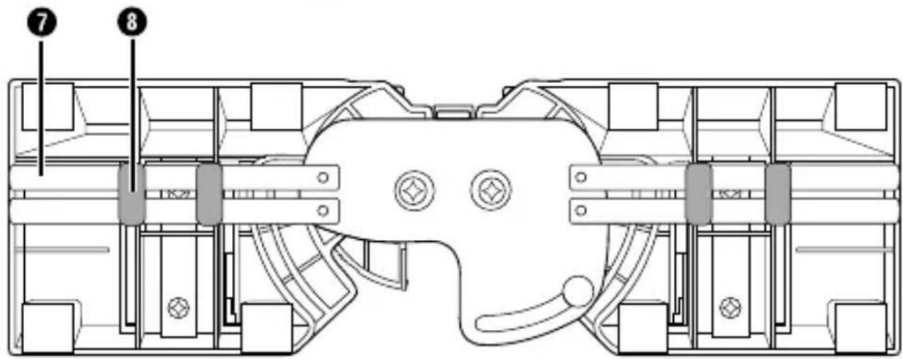
- 4 × guide rods ⑦
- 4 × retaining clips ⑧
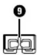
- 1 × cutting guide element A ⑨
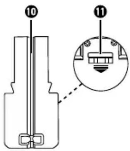
- 1 × cutting guide element B ⑩
-Locking lever ⑪
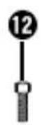
- 4 × screws 12
- 4 × washers ⑬
- 2 × spacer rods 14
- 1 × hex key SW 4 mm ⑮
● These operating instructions
NOTE
▶ Check the package for completeness and signs of visible damage.
If the delivery is incomplete or damage has occurred as a result of defective packaging or during transport, contact the customer service hotline (see section Service).
Assembly
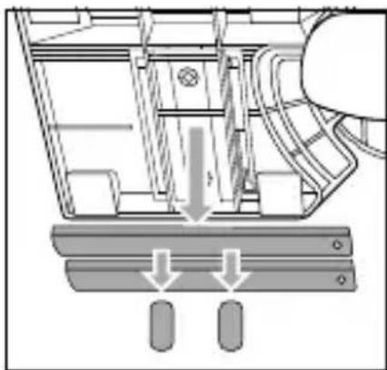
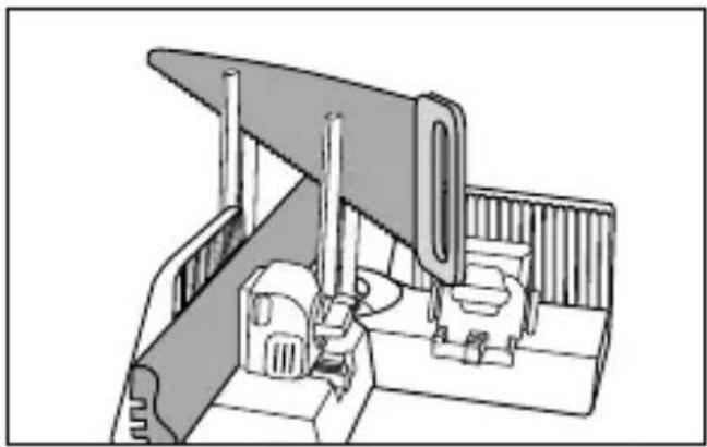
Remove the retaining clips ⑧ from the underside of the product and remove the guide rods ⑦ (see fig. 1). Dispose of the retaining clips ⑧.
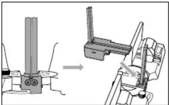
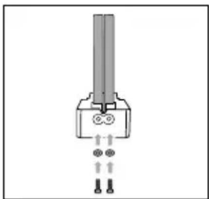
Take two guide rods ⑦, with the rounded side facing each other, and push a spacer rod ⑭ into both guide rods ⑦ (see fig. 2).
- Insert the two guide rods ⑦ into cutting guide element A ⑨ (see fig. 2).
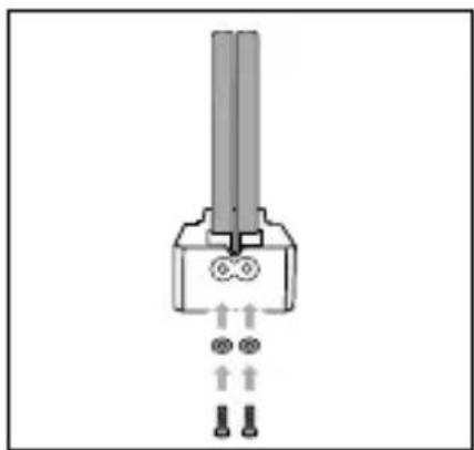
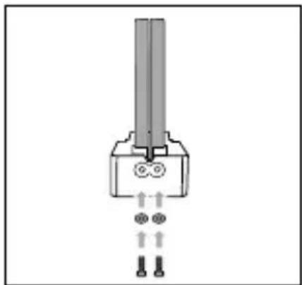
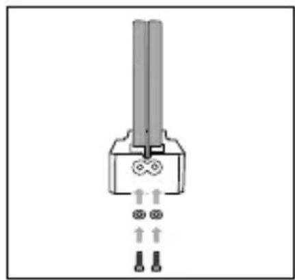
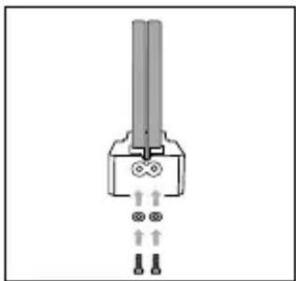
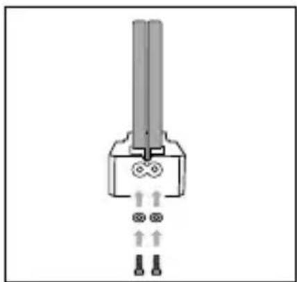
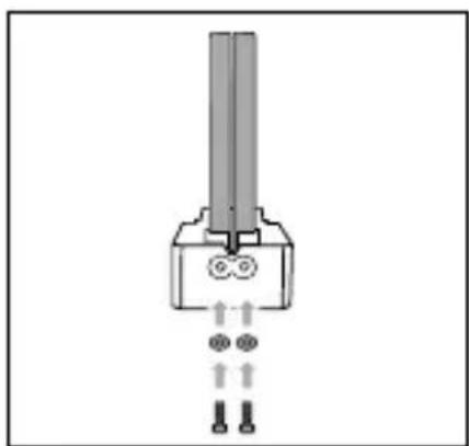
Place a washer 13 into the recess of cutting guide element A 9 and screw a screw 12 with the hex key 15 into the guide rods 7 (see fig. 3).
◆ Repeat the process, to attach the two remaining guide rods ⑦ to cutting guide element B ⑩.
natural_image
Mechanical assembly diagram showing a component with arrows indicating motion or force direction (no text or symbols present)

natural_image
Pure electrical connector diagram without any text, numbers, or symbols▶ Internal and external angles from 85^ to 180^ can be measured.
▶ To measure an external angle, you may need to remove cutting guide elements A ⑨ and B ⑩ (if fitted).
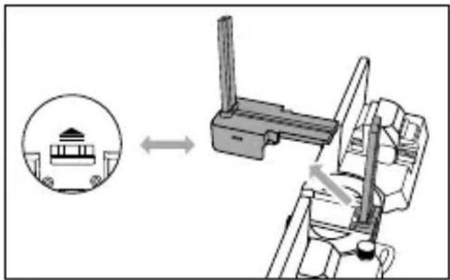
- Undo the retaining nut ⑥ one turn only so that the screw cannot fall out.
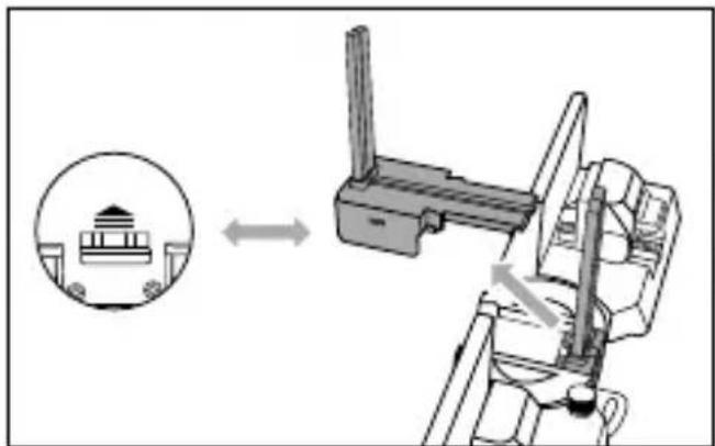
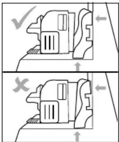
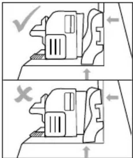
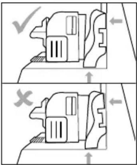
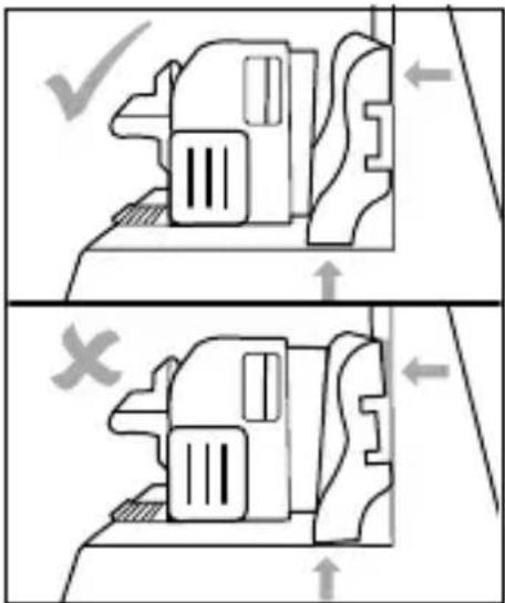
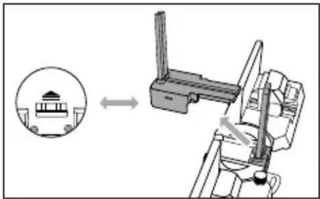
◆ Place the product in or around a corner to measure an inside or outside angle. The movable arms ① must lie flat against the wall (see fig. 4).
- Tighten the retaining nut ⑥. The arrows on the movable arms ① point to the scale where you can read off the measured angle (see fig. 5).

natural_image
Three-panel illustration showing a moving excavator, a truck-mounted device, and a mechanical component with a rotating knob (no text or symbols)Fig. 4 Fig. 5
Inserting cutting guide elements
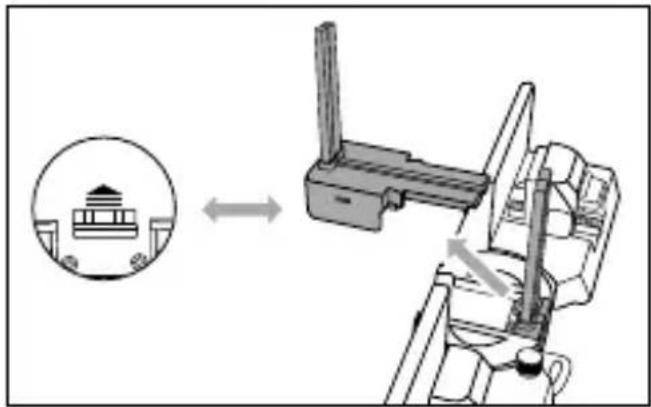
- Insert cutting guide element A ⑨ from above into the recess provided (see fig. 6). Cutting guide element A ⑨ is not initially firmly in place.
- Insert cutting guide element B 10 from above into the recess provided until it clicks into place (see fig. 6).
Removing the cutting guide elements
NOTE
To measure an external angle, you need to remove cutting guide elements A ⑨ and B ⑩.
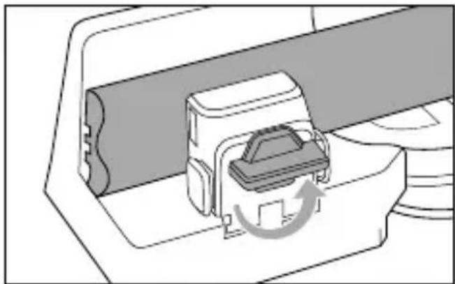
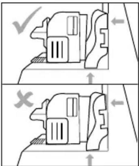
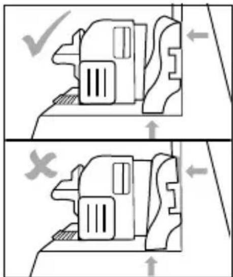
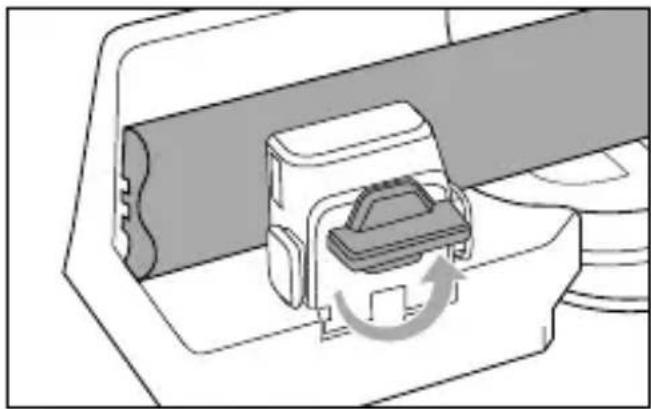
Hold the product with the top side up and press the locking lever 11 in the direction of the arrow ≈ to remove cutting guide element B 10 (see fig. 7).
◆ Remove cutting guide element A ⑨ (see fig. 7).
◆ Caution! If you hold the product upside down during the operation, cutting guide element A ⑨ will fall out automatically.
natural_image
Mechanical assembly diagram showing a lever mechanism with no visible text or symbols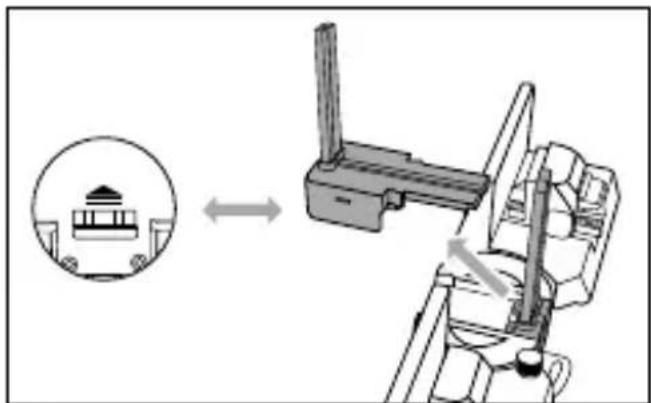
natural_image
Mechanical assembly diagram showing a lever mechanism with a circular inset view of a mechanical component (no text or symbols)Fig. 6 Fig. 7
Clamping and sawing a wooden workpiece
NOTE
▶ You can saw wooden workpieces, e.g. skirting boards, with a max. height of 100 mm and a width of 5 to 30 mm.
Hold down the release buttons ④ and push the tensioning clamp ② onto the wooden workpiece to position it.
Place the wooden workpiece between the retaining jaw ③ and the tensioning clamp ②. Make sure that the wooden workpiece is guided past the guide rods ⑦ (see fig. 8).
Hold down the release buttons ④ and push the tensioning clamp ② onto the wooden workpiece. Let go of the release buttons ④ once the wooden workpiece is clamped (see fig. 8).
- Turn the locking button ⑤ clockwise to fix the wooden workpiece in place (see fig. 8).
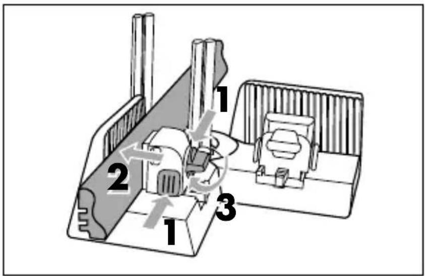
Fig.

8 Fig. 9
- Hold the product firmly with one hand on one of the movable arms ①. In addition, hold onto skirting boards that do not retain a 90^ angle after clamping (see fig. 9).
Using the other hand, guide the saw through the guide rods ⑦ from above (see fig. 10).
◆ Saw through the wooden workpiece.
- Turn the locking button ⑤ anticlockwise to release the wooden workpiece (see fig. 11).
◆ Remove the wooden workpiece.
natural_image
Technical line drawing of a mechanical assembly or mounting bracket with no visible text or symbolsFig. 10 Fig. 11

natural_image
Diagram of a mechanical device with a rotating component and directional arrow (no text or symbols)Cleaning and storage
ATTENTION! PROPERTY DAMAGE!
▶ Do not use aggressive or abrasive cleaning agents, as these can damage the surfaces of the product.
Use a soft dry brush to remove the sawdust from the product.
You can also clean the product using a dry cloth.
◆ Store the product in a clean, dry location away from direct sunlight.
Disposal

Dispose of the product via an approved waste disposal company or your municipal waste disposal facility.
Comply with all applicable regulations. Please contact your waste disposal facility if you are in any doubt.

Your local community or municipal authorities can provide information on how to dispose of the worn-out product.

The product is recyclable, subject to extended producer responsibility and is collected separately.

Dispose of the packaging in an environmentally friendly manner.
Note the labelling on the packaging and separate the packaging material components for disposal, if necessary. The packaging materials are labelled with abbreviations (a) and numbers (b) with the following meanings: 1–7: plastics, 20–22: paper and cardboard, 80–98: composites.
Service

Service Great Britain
Tel.: 0800 404 7657
E-Mail: kompernass@lidl.co.uk

Servicelreland
Tel.: 1800 101010
E-Mail: kompernass@lidl.ie
IAN 380588_2110
Importer
Please note that the following address is not the service address.
Please use the service address provided in the operating instructions.
KOMPERNASS HANDELS GMBH
BURGSTRASSE 21
44867 BOCHUM
GERMANY
www.kompernass.com
Inhaltsverzeichnis
Einführung 14
natural_image
Technical diagram of a mechanical assembly with arrows indicating force or movement (no text or symbols present)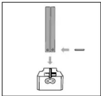
natural_image
Pure electrical connector diagram without any text, numbers, or symbolsnatural_image
Three-panel illustration showing a moving excavator, a tool holder, and a mechanical component with a rotating knob (no text or symbols)Abb. 4 Abb. 5
natural_image
Mechanical assembly diagram showing a lever mechanism with a bracket and guide mechanism (no text or symbols)Abb. 6 Abb. 7
natural_image
Diagram showing a mechanical assembly with an inset circular view of a traditional building (no text or symbols present)Abb.

8 Abb. 9
natural_image
Technical line drawing of a mechanical assembly or mounting bracket (no text or symbols visible)Abb.
natural_image
Diagram of a mechanical device with a rotating component and directional arrow (no text or symbols)10
Abb.
natural_image
Simple line drawing of a four chasing recycling symbol (no text or labels)KOMPERNASS HANDELS GMBH
BURGSTRASSE 21
44867 BOCHUM
DEUTSCHLAND
www.kompernass.com
Table des matières
Introduction 26
natural_image
Mechanical assembly diagram showing a piston and roller mechanism (no text or labels)Fig. 1
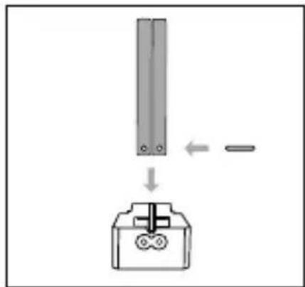
Fig. 2
natural_image
Pure electrical connector diagram without any text, numbers, or symbolsFig. 3
Utilisation
Mesurer un angle
REMARQUE
natural_image
Line drawing of two mechanical devices with no visible text or symbols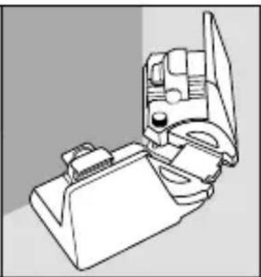
natural_image
Line drawing of a mechanical device with no visible text or symbols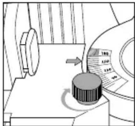
Fig. 4 Fig. 5
natural_image
Mechanical assembly diagram showing a lever mechanism with a bracket and guide mechanism (no text or symbols)Fig. 6

natural_image
Diagram showing a mechanical device with an inset circular view of a building (no text or symbols)Fig. 7
Fig.
8 Fig. 9
natural_image
Technical line drawing of a mechanical assembly or mounting bracket with no visible text or symbolsFig. 10 Fig. 11

natural_image
Diagram of a mechanical device with a rotating component and directional arrow (no text or symbols)KOMPERNASS HANDELS GMBH
BURGSTRASSE 21
44867 BOCHUM
ALLEMAGNE
www.kompernass.com
Inhoud
Inleiding 38
natural_image
Technical diagram showing a mechanical assembly with two components and directional arrows indicating motion (no text or symbols)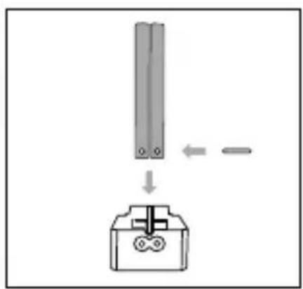
natural_image
Pure electrical connector diagram without any text, numbers, or symbolsnatural_image
Technical line drawing of a mechanical device with a lever and base (no text or symbols)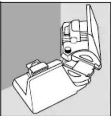
natural_image
Line drawing of a mechanical device with no visible text or symbols
Afb. 4 Afb. 5
natural_image
Mechanical assembly diagram showing a lever mechanism with no visible text or symbolsAfb. 6 Afb. 7

natural_image
Mechanical assembly diagram showing a lever mechanism with a circular inset view of a mechanical component (no text or symbols)Abb.
8 Abb. 9
natural_image
Technical line drawing of a mechanical assembly or mounting bracket with no visible text or symbolsAfb. 10 Afb. 11

natural_image
Diagram of a mechanical device with a rotating component and directional arrow (no text or symbols)Reinigen en opbergen
LET OP! MATERIÈLE SCHADE!
KOMPERNASS HANDELS GMBH
BURGSTRASSE 21
44867 BOCHUM
DUITSLAND
www.kompernass.com
Obsah
Úvod 50
natural_image
Mechanical assembly diagram showing a piston and connecting rod components (no text or labels)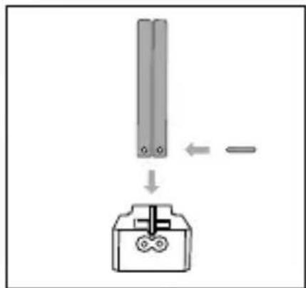

natural_image
Pure electrical connector diagram without any text, numbers, or symbolsObr. 1 Obr. 2 Obr. 3
Použití
Měření úhlu
UPOZORNĚNÍ
natural_image
Three-panel illustration showing a bulldozer, a moving truck, and a mechanical component with a rotating dial (no text or symbols)Obr. 4 Obr. 5
Obr. 6
natural_image
Diagram showing a mechanical device with an inset image of a traditional Chinese building (no text or symbols present)Obr.
7
Obr.
8
Obr. 9
natural_image
Technical line drawing of a mechanical assembly or mounting bracket (no text or symbols visible)Obr.
10

natural_image
Diagram of a mechanical component with a rotating arrow indicating motion (no text or symbols)Obr. 11
POZOR! HMOTNÉ ŠKODY!
KOMPERNASS HANDELS GMBH
BURGSTRASSE 21
44867 BOCHUM
NĚMECKO
www.kompernass.com
Spis treści
Wstep. 62
natural_image
Technical diagram of a mechanical assembly with arrows indicating force or movement (no text or symbols present)

natural_image
Pure electrical connector diagram without any text, numbers, or symbolsnatural_image
Three-panel line drawing showing a bulldozer, a moving truck, and a mechanical component with a rotating knob (no text or symbols)Rys. 4 Rys. 5
natural_image
Mechanical assembly diagram showing a lever mechanism with no visible text or symbolsRys. 6 Rys. 7

natural_image
Mechanical assembly diagram showing a lever mechanism with a circular inset view of a mechanical component (no text or symbols)Rys.
8 Rys. 9
natural_image
Technical line drawing of a mechanical assembly or machine component (no visible text or symbols)Rys. 10 Rys. 11

natural_image
Diagram of a mechanical device with a rotating component and directional arrow (no text or symbols)KOMPERNASS HANDELS GMBH
BURGSTRASSE 21
44867 BOCHUM
NIEMCY
www.kompernass.com
Obsah
Úvod 74
natural_image
Mechanical assembly diagram showing a piston and connecting rod components (no text or labels)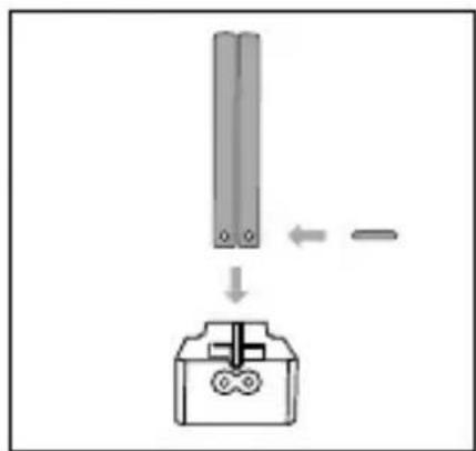
natural_image
Pure electrical connector diagram without any text, numbers, or symbolsObr. 1 Obr. 2 Obr. 3
Použitie
Meranie uhla
UPOZORNENIE
natural_image
Three-panel line drawing showing a bulldozer, a moving truck, and a mechanical component with a rotating knob (no text or symbols)Obr. 4 Obr. 5

natural_image
Diagram showing a mechanical device with an inset circular view of a traditional building (no text or symbols present)Obr. 6 Obr. 7
Obr.
8 Obr. 9
natural_image
Technical line drawing of a mechanical assembly or mounting bracket (no text or symbols visible)Obr. 10 Obr. 11

natural_image
Diagram of a mechanical component with a rotating arrow indicating motion (no text or symbols)KOMPERNASS HANDELS GMBH
BURGSTRASSE 21
44867 BOCHUM
NEMECKO
www.kompernass.com
Índice
Introducción 86
natural_image
Technical diagram of a mechanical assembly with arrows indicating force or movement (no text or symbols present)Fig. 1
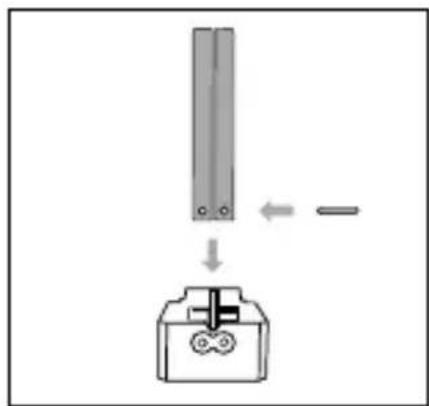
Fig. 2

natural_image
Pure electrical connector diagram without any text, numbers, or symbolsFig. 3
Utilización
Medición de ángulos
INDICACIÓN
natural_image
Two technical line drawings of a mechanical device, one with a bracket and the other with a truck (no text or symbols)Fig. 4
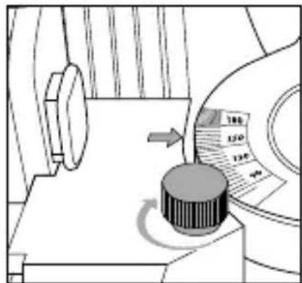
Fig. 5
natural_image
Mechanical assembly diagram showing a lever mechanism and a close-up of the lever assembly (no text or symbols)Fig. 6

natural_image
Mechanical assembly diagram showing a lever mechanism with a circular inset view of a traditional building (no text or symbols)Fig. 7

Fig. 8 Fig. 9
natural_image
Technical line drawing of a mechanical assembly or mounting bracket (no text or symbols visible)Fig. 10

natural_image
Diagram of a mechanical device with a rotating component and directional arrow (no text or symbols)Fig. 11
KOMPERNASS HANDELS GMBH
BURGSTRASSE 21
44867 BOCHUM
ALEMANIA
www.kompernass.com
Indholdsfortegnelse
Introduktion 98
natural_image
Mechanical assembly diagram showing a component with arrows indicating motion or force direction (no text or symbols present)

natural_image
Pure electrical connector diagram without any text, numbers, or symbolsnatural_image
Three-panel technical illustration showing mechanical components and a rotary knob (no text or symbols)Fig. 4 Fig. 5
natural_image
Mechanical assembly diagram showing a lever mechanism and a close-up of a mechanical component (no text or symbols)Fig. 6 Fig. 7

natural_image
Diagram showing a mechanical device with an inset circular view of a traditional building (no text or symbols present)Fig.
8 Fig. 9
natural_image
Technical line drawing of a mechanical assembly or mounting bracket with no visible text or symbolsFig. 10 Fig. 11

natural_image
Diagram of a mechanical device with a rotating component and directional arrow (no text or symbols)KOMPERNASS HANDELS GMBH
BURGSTRASSE 21
44867 BOCHUM
TYSKLAND
www.kompernass.com
Indice
natural_image
Mechanical assembly diagram showing a piston and connecting rod components (no text or labels)
natural_image
Pure electrical connector diagram without any text, numbers, or symbolsnatural_image
Three-panel illustration showing a vehicle climbing a ramp, a gear shift, and a mechanical component with a rotating knob (no text or symbols)Fig. 4 Fig. 5
natural_image
Mechanical assembly diagram showing a lever mechanism with a bracket and guide mechanism (no text or symbols)Fig. 6 Fig. 7

natural_image
Diagram showing a mechanical assembly with an inset circular view of a traditional building (no text or symbols)Fig.

8 Fig. 9
natural_image
Technical line drawing of a mechanical assembly or mounting bracket with no visible text or symbolsFig. 10 Fig. 11

natural_image
Diagram of a mechanical device with a rotating component and directional arrow (no text or symbols)KOMPERNASS HANDELS GMBH
BURGSTRASSE 21
44867 BOCHUM
GERMANIA
www.kompernass.com
Tartalomjegyzék
Bevezető 122
natural_image
Mechanical assembly diagram showing a piston and roller mechanism (no text or labels)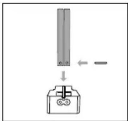
natural_image
Pure electrical connector diagram without any text, numbers, or symbolsnatural_image
Three-panel illustration showing a bulldozer, a moving truck, and a mechanical component with a rotating dial (no text or symbols)- ábra 5. ábra
natural_image
Mechanical assembly diagram showing a lever mechanism before and after assembly (no text or symbols)- ábra
natural_image
Mechanical assembly diagram showing a lever mechanism with a circular inset view of a mechanical component (no text or symbols)- ábra

- ábra 9. ábra
natural_image
Technical line drawing of a mechanical assembly or mounting bracket with no visible text or symbols- ábra 11. ábra

natural_image
Diagram of a mechanical device with a rotating component and directional arrow (no text or symbols)KOMPERNASS HANDELS GMBH
BURGSTRASSE 21
44867 BOCHUM
NÉMETORSZÁG
www.kompernass.com
Kazalo
Uvod ....134
Informacije o teh navodilih za uporabo .... 1 3 4
Predvidena uporaba.... 134
Varna uporaba .... 1 3 5
Obseg dobave/opis delov .... 1 3 6
Sestavljanje....13
Uporaba 138
Merjenje kotov 13
natural_image
Technical diagram showing a mechanical assembly with two downward arrows indicating force or movement (no text or symbols present)
natural_image
Pure electrical connector diagram without any text, numbers, or symbolsnatural_image
Three-panel line drawing showing a mechanical device before and after assembly, with a close-up of the component being turned into a circular dial (no text or symbols)Slika
4
natural_image
Mechanical assembly diagram showing a lever mechanism with a bracket and guide mechanism (no text or labels)Slika 6 Slika 7
natural_image
Mechanical assembly diagram showing a lever mechanism with a circular inset view of a mechanical component (no text or symbols)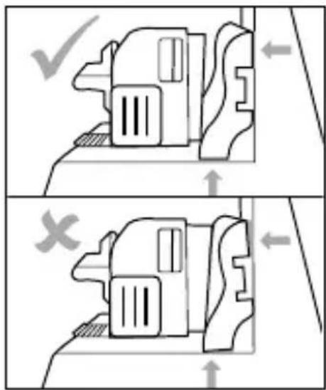
Slika 8 Slika 9
natural_image
Technical line drawing of a mechanical assembly or mounting bracket with no visible text or symbolsSlika 10
natural_image
Diagram of a mechanical component with a rotating arrow indicating motion (no text or symbols)Slika 11
Čiščenje in shranjevanje
POZOR! MATERIALNA ŠKODA!
KOMPERNASS HANDELS GMBH
BURGSTRASSE 21
44867 BOCHUM
NEMČIJA
www.kompernass.com
Pooblaščeni serviser

ServisSlovenija
Tel.: 080 080 917
E-Mail: kompernass@lidl.si
IAN 380558_2110


KOMPERNASS HANDELS GMBH
BURGSTRASSE 21
44867 BOCHUM
GERMANY
www.kompernass.com
Last Information Update · Stand der Informationen · Version des informations
Stand van de informatie · Stav informací · Stan informacji · Stav informácií
Estado de las informaciones · Tilstand af information · Versione delle informazioni
- BOÎTE À ONGLET RÉGLABLE
- Contents
- Introduction 2
- Safety 3
- Contents of package/parts description ..... 4
- Assembly 5
- Use....6
- Cleaning and storage 9
- Disposal....10
- Service 11
- Importer ....11
- Introduction
- Information about these operating instructions
- Proper use
- Safety
- Contents of package/parts description
- NOTE
- Assembly
- Inserting cutting guide elements
- Removing the cutting guide elements
- Clamping and sawing a wooden workpiece
- Cleaning and storage
- ATTENTION! PROPERTY DAMAGE!
- Disposal
- Service
- Service Great Britain
- Servicelreland
- Importer
- Inhaltsverzeichnis
- Einführung 14
- Table des matières
- Introduction 26
- Utilisation
- Mesurer un angle
- REMARQUE
- Inhoud
- Inleiding 38
- Reinigen en opbergen
- LET OP! MATERIÈLE SCHADE!
- Obsah
- Úvod 50
- Použití
- Měření úhlu
- UPOZORNĚNÍ
- POZOR! HMOTNÉ ŠKODY!
- Spis treści
- Wstep. 62
- Úvod 74
- Použitie
- Meranie uhla
- UPOZORNENIE
- Índice
- Introducción 86
- Utilización
- Medición de ángulos
- INDICACIÓN
- Indholdsfortegnelse
- Introduktion 98
- Indice
- Tartalomjegyzék
- Bevezető 122
- Kazalo
- Uvod ....134
- Varna uporaba .... 1 3 5
- Obseg dobave/opis delov .... 1 3 6
- Sestavljanje....13
- Uporaba 138
- Čiščenje in shranjevanje
- POZOR! MATERIALNA ŠKODA!
- Pooblaščeni serviser
- KOMPERNASS HANDELS GMBH
Brand : PARKSIDE
Model : IAN 380558
Category : Adjustable tab box