34151 - Gas detector CHACON - Free user manual and instructions
Find the device manual for free 34151 CHACON in PDF.
| Product Type | Gas Detector |
| Brand | Chacon |
| Model | 34151 |
| Gases detected | Methane (CH4), biogas, natural gas |
| Dimensions (L x W x H) | 112 mm x 86 mm x 33.5 mm |
| Power supply | AC 100V~220V / 50Hz~60Hz |
| Power consumption | ≤4W |
| Sensor type | Semiconductor |
| Sensor lifespan | 5 years |
| Alarm threshold | 7%LEL ±3%LEL |
| Alarm mode | Audible (≥85dB) + visual (flashing red LED) |
| Response time | ≤30s |
| Operating environment | Temperature 0°C to 55°C, humidity <95% (non-condensing) |
| Atmospheric pressure | 86kPa~106kPa |
| Storage temperature | -25°C to 55°C |
| Installation | Wall mounting, ≤30 cm from ceiling, 1-4 m from gas appliance |
| Standard | EN 50194-1:2009 |
| Usage | Indoor only |
| Main functions | Gas leak detection, audible and visual alarm, self-test, lifespan indication, warm-up |
| Maintenance and cleaning | Clean monthly with a brush or soft dry cloth |
| Safety | Do not install near drafts, humidity, heat sources; do not disassemble |
| Repairability | Do not repair yourself, contact the distributor |
Frequently Asked Questions - 34151 CHACON
User questions about 34151 CHACON
0 question about this device. Answer the ones you know or ask your own.
Ask a new question about this device
Download the instructions for your Gas detector in PDF format for free! Find your manual 34151 - CHACON and take your electronic device back in hand. On this page are published all the documents necessary for the use of your device. 34151 by CHACON.
USER MANUAL 34151 CHACON
natural_image
White Chacon electric shock absorber device with visible ports and speaker grille (no text or symbols on body)www.chacon.com
text_image
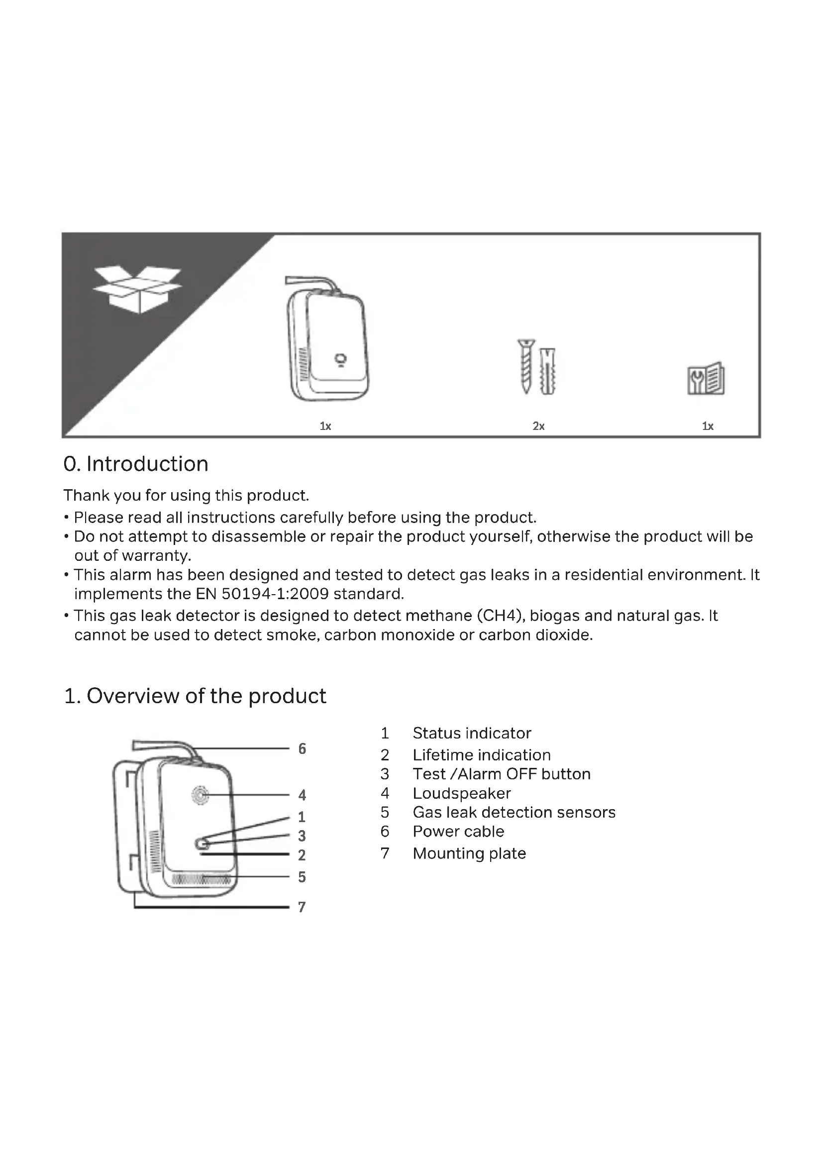
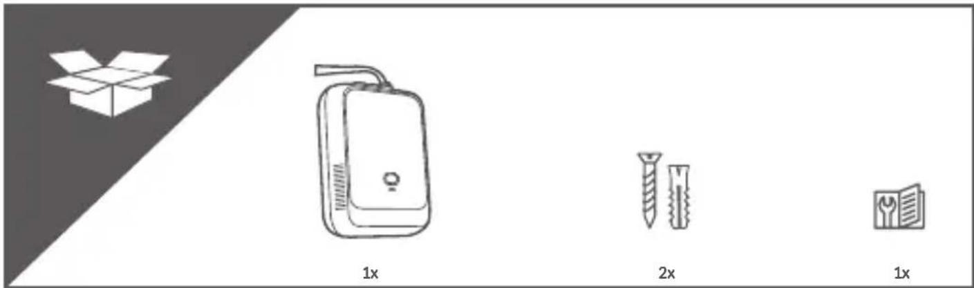
1x 2x 1x0. Introduction
Thank you for using this product.
- Please read all instructions carefully before using the product.
- Do not attempt to disassemble or repair the product yourself, otherwise the product will be out of warranty.
- This alarm has been designed and tested to detect gas leaks in a residential environment. It implements the EN 50194-1:2009 standard.
- This gas leak detector is designed to detect methane (CH4), biogas and natural gas. It cannot be used to detect smoke, carbon monoxide or carbon dioxide.
1. Overview of the product
text_image
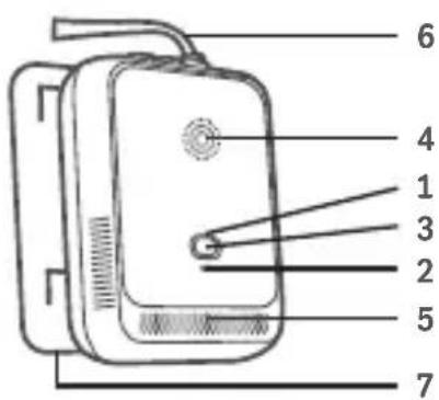
Diagram of a device with numbered parts labeled 1 through 7, likely for labeling or assembly instructions.1 Status indicator
2 Lifetime indication
3 Test /Alarm OFF button
4 Loudspeaker
5 Gas leak detection sensors
6 Power cable
7 Mounting plate
1.1. Product Installation
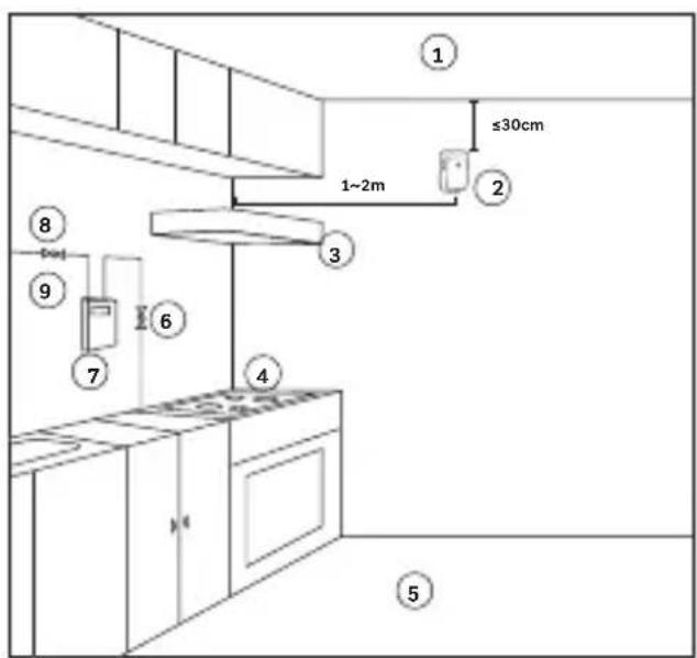
This detector is suitable for indoor use only. This device is recommended near your cooker, water heater, and near any gas-fired source. It should be installed 1m\~4m from the gas appliance and maximum 30 centimetres from the ceiling.
Tip: It is advisable to check that the device is working properly before installing the detector on its mounting plate. Make sure that the location is close to a power source (socket).
text_image
1 ≤30cm 1~2m 2 3 4 5 6 7 8 91 Ceiling
2 Methane Gas Detector
3 Kitchen ventilator
4 Gas stove
5 Ground
6 Ball valve
7 Gas meter
8 Inlet ball valve
9 Gas
2. Indication of product operation
2.1. Connecting the device to the power source
When you plug in the detector, the status indicator LED flashes green. Then it automatically goes into warm-up mode for 3 minutes. During this time, the unit cannot detect gas leaks. After 3 minutes, the green LED will light up to let you know that it is operational and ready for use.
2.2. The status indicator turns red
When the gas concentration value in the air reaches the set alarm point, the detector enters the alarm mode. An audible alarm of 85dB will sound and the status indicator will flash red. Open the windows immediately and turn off the gas valve. Do not turn on or plug in any electrical appliances. If the alarm does not stop, please leave your home, and call for help. If necessary, ask your electrical and gas inspection expert to come and check your installation.
Note: In the alarm state, when the gas concentration is below the safe value, the detector automatically disarms the alarm.
2.3. Failure warning
If the LED on the status indicator is yellow and lights up continuously and beeps, it means that the detector is defective and cannot detect properly, please contact the distributor for repair.
Tip: We advise you to check the device daily. To do so, please press the central button once, the detector will enter the alarm simulation mode and will emit an audible and luminous alarm signal, the red LED will flash and beep, then it will return to the normal detection state.
2.4. End of life warning
If the lifetime indicator flashes 3 times continuously and at the same time beeps 3 times, the lifetime of the sensor has expired. Please contact your dealer if your warranty is still valid or get a new sensor.
2.5. Device status summary
| Mode LED indicator Lifetime indicator Alarm | ||
| Preheat mode Flashing green LED // | ||
| Normal mode Continuous green LED // | ||
| Test mode Red LED ashing / Beeps 4x | ||
| Fault mode Continuous yellow LED / Continuous beep | ||
| Alarm mode Flashing red led / Beeps 4x repeating | ||
| End of product life / Flash Beeps 3x repeatedly |
3. Advice - installation locations
We recommend that you install the gas leak detector near your cooker, water heater and near all gas sources. Methane (or town gas), biogas or natural gas is lighter than air and therefore rises, so place your device of about 30 cm from the ceiling.
To avoid damage to the product and to prevent false alarms, do not install the unit in the following locations:
• Air inlet/outlet areas, exhaust fans, doors/windows with strong air circulation.
- Areas with moisture and water drops, e.g. in your bathroom.
- Areas directly above a source of heat or steam.
Note: If the room must be painted or renovated, please install the detector after the renovation or painting work.
4. Troubleshooting
Note: For any faults that cannot be resolved by yourself, do not dismantle the detector, please contact the distributor for advice.
| Faulty Possible reason(s) Action(s) | to be taken | |
| The green light of the power source is not on | Power source cable not connected properly | Check and connect the cable to the power source correctly |
| Power source indicator damaged or circuit failure | Contact the distributor for repair |
| No audible and visual alarm during self-test | Circuit failure Contact the distributor for repair |
| No response to detected gas Still preheating Wait for the warm-up to finish | |
5. Maintenance advice
The product must be kept clean when in use, otherwise its performance will be affected and may even damage the alarm. It should be cleaned and tested at least once a month.
- Please clean dust or oil contamination on the surface of the detector regularly with a soft, dry brush or cloth. After cleaning, reinstall the detector on its base plate and perform a function check.
• After long storage or transportation, please turn on the detector and wait 24 hours or more for optimum performance. - This product cannot be used or stored in an environment containing corrosive gases (such as chlorine)
- The presence of large amounts of cigarette smoke, alcohol, or volatile organic compounds such as petrol, perfume or paints in the room may trigger the detector's alarm.
- The detector must be connected to a stable power source.
Note: In a normal operating environment, the solid-state sensor can operate for 5 years.
6. Preventive actions for heating, hot water and in the kitchen
- Have your flues and chimneys swept once a year, which is the minimum requirement, or twice for extra precaution.
- Have your installation checked regularly, for example as part of a maintenance contract. It is also compulsory to have your boiler serviced every year.
- Clean the ventilation grilles regularly and never place a piece of furniture, a towel, or any other object in front of a ventilation opening so as not to obstruct the escape of gases.
- Ventilate your home regularly.
- Turn off the natural gas tap every time you leave for the weekend or on holiday.
- Clean the burners of your gas cooker regularly: a blue flame is a guarantee of safety.
- If your cooker is connected via a flexible tube, replace it with a flexible tube with mechanical screwed ends, which is very difficult to tear off; if you already have a flexible tube, check its
validity date.
CAUTION: If you detect a leak, ventilate immediately, turn off the natural gas supply and avoid actions that could cause a spark (e.g. touching switches or circuit breakers, turning on the light, making a phone call from a landline or mobile phone, etc.)
If the leak is ignited, there is no longer any risk of explosion: if possible, close the appliance's supply valve or the natural gas supply, wet the nearby surfaces, evacuate the building, and call for help.
7. Technical specifications
| Gas detected methane (CH4), biogas and natural gas | |
| Size (L*W*H) 112mm*86mm*33.5mm | |
| Operating voltage AC 100V~220V/50Hz~60Hz | |
| Power consumption ≤4W | |
| Operating environment Temperature: 0°C~55°C | |
| Relative humidity: <95% (non-condensing) | |
| Ambient pressure: 86kPa~106kPa | |
| Storage temperature -25°C~55°C | |
| Response time ≤30s | |
| Sensor type semi-conductor | |
| Sensor lifetime 5 years | |
| Alarm value 7%LEL±3%LEL | |
| Alarm mode Sound + light | |
| Alarm sound level ≥85dB | |
| Installation Wall mounted | |
| Standard EN 50194-1:2009 |

text_image
1x 2x 1x0. Introduction
text_image
Diagram of a device with numbered parts labeled 1 through 7, likely for labeling or assembly instructions.text_image
Diagram of a device with numbered parts labeled 1 through 7, likely for labeling or identification.text_image
Diagram of a device with numbered parts labeled 1 through 7, likely for labeling or assembly instructions.text_image
Diagram of a device with numbered parts labeled 1 through 7, likely for labeling or identification.text_image
Diagram of a device with numbered parts labeled 1 through 7, likely for labeling or identification.text_image
Diagram of a device with numbered parts labeled 1 through 7, likely for labeling or assembly instructions.EN: This product must be treated in accordance with European Directive 2002/96/EC with the aim of being recycled or dismantled to minimise its impact on the environment. For further information, please contact your local or regional authorities.