USER MANUAL 34895 CHACON
natural_image
Three medical or laboratory probe tubes with different tip positions (no text or symbols visible)
1×
1×1×

name

8×1×1×

natural_image
Illustration of a wall-mounted electronic device with a central screen and control buttons (no text or symbols)
natural_image
Pure mechanical diagram showing a lever mechanism with no text or symbols

natural_image
Diagram of a connector with pins and a cable, no text or symbols present
natural_image
Diagram showing a cable being inserted into a device, with no visible text or symbols
Etape 1
Etape 3
Etape 4
natural_image
Three medical or laboratory probe tubes with different tip positions (no text or symbols visible)
1×

1×1×


name

8×1×1×

natural_image
Illustration of a wall-mounted electronic device with a central screen and control buttons (no text or symbols)
natural_image
Pure mechanical diagram showing a lever mechanism with no text or symbols

natural_image
Diagram of a connector with pins and a cable, no text or symbols present
4.1 Buitenunit
4.2 Scherm
natural_image
Diagram of a cable connection between an open panel and a mounted device (no text or symbols present)
Stap 1
Stap 3
Stap 4
natural_image
Three medical or laboratory instruments with no visible text or symbols
1×
1×1×


8×1×1×

natural_image
Illustration of a wall-mounted security camera with control panel and display (no text or symbols)
natural_image
Pure mechanical diagram showing a lever mechanism with pivot point and angle θ annotations (no text or symbols beyond basic geometry)

natural_image
Diagram of a connector with pins and a cable, no text or symbols present
4.1 Unidad exterior
4.2 Pantalla
natural_image
Diagram showing cable connection between a device with labeled components and wiring (no text or symbols present)
Paso 1
Paso 3
Paso 4
natural_image
Three medical or laboratory instruments with no visible text or symbols
1×
1×1×


8×1×1×


natural_image
Illustration of a wall-mounted security camera with control panel and display (no text or symbols)
natural_image
Pure mechanical diagram showing a lever mechanism with pivot point and angle θ annotations (no text or symbols beyond basic geometry)
natural_image
Diagram of a connector with pins and a cable, no text or symbols present
4.2 Ecră
natural_image
Diagram of a cable connection between two electronic devices, one with a terminal block and cable, the other with a cable (no text or symbols present)
Etapa 1
Etapa 3
Etapa 4
natural_image
Three medical or laboratory probe tubes with different tip positions (no text or symbols visible)
1×

1×1×


name

8×1×1×
natural_image
Illustration of a wall-mounted electronic device with a central screen and control buttons (no text or symbols)
natural_image
Pure mechanical diagram showing a lever and shaft assembly without any text, numbers, or symbols
natural_image
Diagram of a connector with pins and a cable, no text or symbols present
4.1 Unità esterna
4.2 Display
natural_image
Diagram showing wiring connection between a device panel and a terminal block (no text or symbols present)
Step 1
Step 3
Step 4
Please take note before installation!
Check that these points are respected
- Make sure that the cables between the 2 units are well connected (see chapter 4 of the manual)
- Follow the steps of the configuration wizard (see chapter 5 of the manual)
- Wait for the 2 units to connect automatically
At the top right of your screen, you will see 3 types of icons that scroll successively:
- No device is connected
- Connection failure
- SIR Connection between the 2 units
The videophone is functional as soon as the icon SIR is visible in your screen on the top right.
If this is not the case, please do a reset by pressing ⏻ on your screen via the configuration and go back to step 1.

To help you with your installation, you will find below our installation help videos: https://www.youtube.com/watch?v=yxAeUNXFIBE
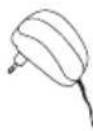
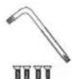
1. Package contents

1×
1×
1×1×1×
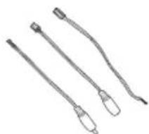
natural_image
Three medical or laboratory probe tubes with different tip positions (no text or symbols visible)
1×
1×1×

name

8×1×1×
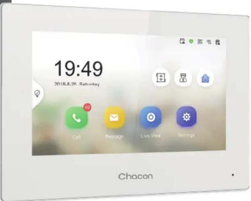
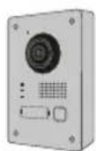
2. Description of the product
2.1 Exterior unit 2.2 Connectors
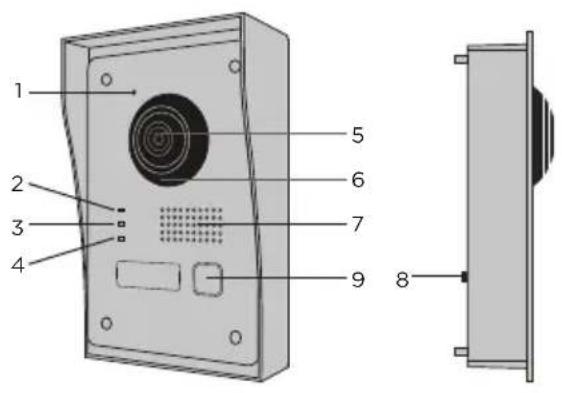
1 Microphone
2 Call indicator
3 Call in progress
4 Door open indicator
5 Camera
6 Infrared
7 Speaker
8 Anti-theft button
9 Call button
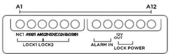
| A1 NC1 Normally Closed |
| A2 ND1 Normally Open |
| A3 COM Common |
| A4 | NC2 Normally Closed |
| A5 | NO2 Normally Open |
| A6 GND Neutral |
| A7 | AIN1 | Entrance alarm 1 |
| A8 A | N2 Entrance alarm 2 |
| A9 | 12V OUT | 12 V outlet for electric bolt |
| A10 | GND Neutral |
| A11 2-WIRE Red cable inner board |
| A12 | 2-WIRE | Black cable inner board |
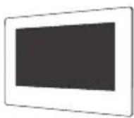
2.3 7" Screen
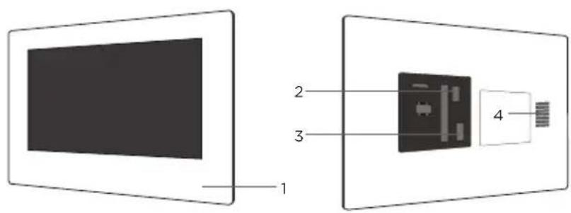
1 Microphone
2 Exterior unit connector
3 24V power connector or power cable from electrical panel
4 Speaker
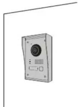
3. Mounting the videophone
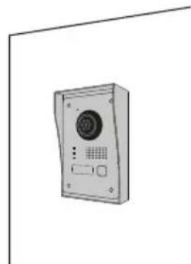
3.1 Exterior unit
Before you start
- Make sure there is no power supply to the screen.
- Connect the cable for the exterior unit before mounting
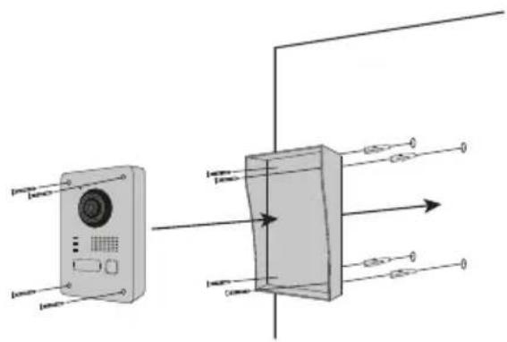
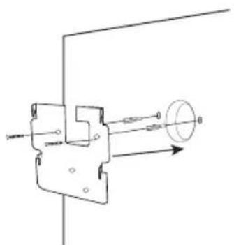
A. No flush-mounting

natural_image
Illustration of a wall-mounted security camera with control panel and display (no text or symbols)
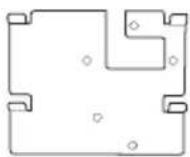
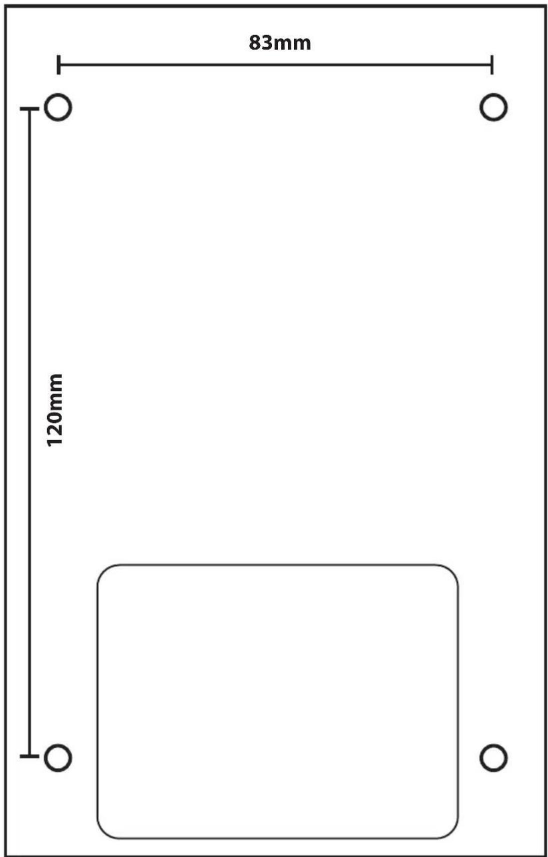
1) Make a space in your wall large enough to fit the protective cover (Dimensional diagram)
2) Insert the pins into the holes and fix the protective cover using the screws provided.
3) Pass the cable through
4) Connect the screen wire to the outdoor unit. Make sure that the 2 units are correctly connected. (Diagram - 2 units)
5) Before attaching the outdoor unit to the protective cover, connect the wires. Refer to the different diagrams and connect the one that corresponds to your house (Diagram Lock + Gates - 2 Gates - 2 Lock)
6) Use the screws provided to fix the exterior unit to the protective cover
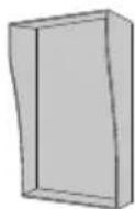
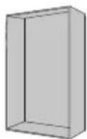
B. Flush mounting
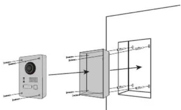
1) Make a space in your wall large enough to fit the flush-mounting box
2) Make 4 holes in line with the position show on the flush-mounting box (Dimensional diagram)
3) Insert the pins into the holes and fix the flush-mounting box using the screws provided.
4) Pass the cable through
5) Connect the screen wire to the outdoor unit. Make sure that the 2 units are correctly connected. (Diagram - 2 units)
6) Before attaching the outdoor unit to the flush-mounting box, connect the wires. Refer to the different diagrams and connect the one that corresponds to your house (Diagram Lock + Gates - 2 Gates - 2 Lock)
7) Use the screws provided to fix the exterior unit to the flush-mounting box
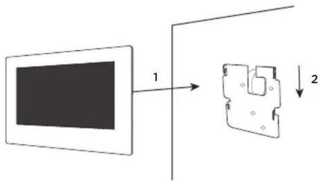
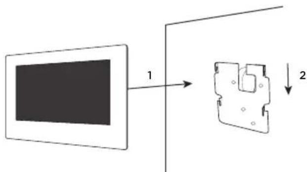
3.2 7" Screen
natural_image
Pure mechanical diagram showing a lever and shaft assembly without any text, numbers, or symbols

1) Make 4 holes in line with positions shown on the wall bracket.
2) Make a hole in your wall to hide the electrical domino
3) Insert the pins into the holes and fix the wall bracket using the screws provided.
4) Connect the power cable and the outdoor unit wire (to do this you must use a terminal block between the 2 connectors to connect the screen to the outdoor unit).
5) Place the screen on the wall bracket as described in the picture.
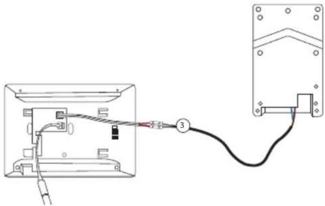
4. Connection of the 2 units
natural_image
Diagram of a connector with pins and a cable, no text or symbols present
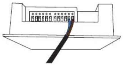
4.1 Outdoor unit
Note: A small flat screwdriver is required to connect the wires. Press the button (☑) with the flat screwdriver to insert the cables. Connect the cable that will connect the outdoor unit to the display. (Check that the cables between the 2 units are well connected).

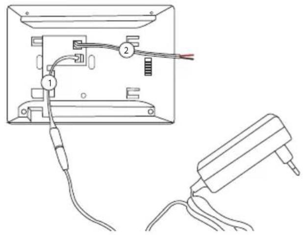
4.2 Screen
- Clip on the 24V power connector (*)
- Clip on the outdoor unit connector
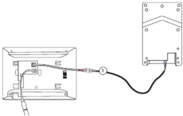
natural_image
Diagram showing wiring connection between a device panel and a terminal block (no text or symbols present)
- Connect the cable that links the 2 units
- Connect to power supply
(*) Additional option for powering the display.
Power cable for electrical panel
You can connect the power of your videophone directly to your electrical panel. You need to install a modular transformer (not included). The specific power cable is provided to allow you this type of installation.
For more information, see our installation videos.
Please wait 1 minute before turning on the screen
5. Inicial configuration
5.1 Configuration wizard
The first time you turn on the display, a wizard will guide you to configure the main settings of your videophone.
Please follow these steps before using the device.
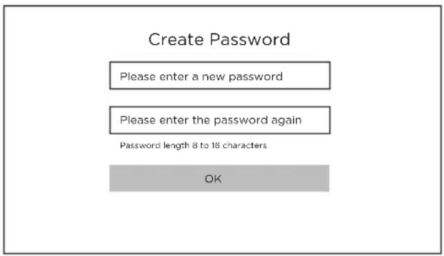
Step 1
Turn on the screen. An activation page will appear. Choose an administrator password for later access to the configuration menu.
Press OK to activate it.

ATTENTION: Please write down your password somewhere! (at the back of the screen). You will be asked for it every time you want to change a setting.
We recommend that you create a strong password of your choice (using a minimum of 8 characters, including at least three types of the following categories: uppercase letters, lowercase letters, numbers and special characters) to increase the security of your product.
Password: ....
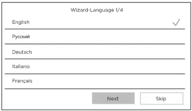
Step 2
Select your language
(This step will have to be reconfirmed later by going through the configuration again so that both units have the same language).
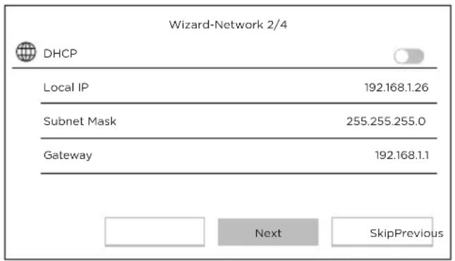
Step 3
Configure a local network between the interior and exterior units.
We advise that you do not select the DHCP option and you stick to the default settings.
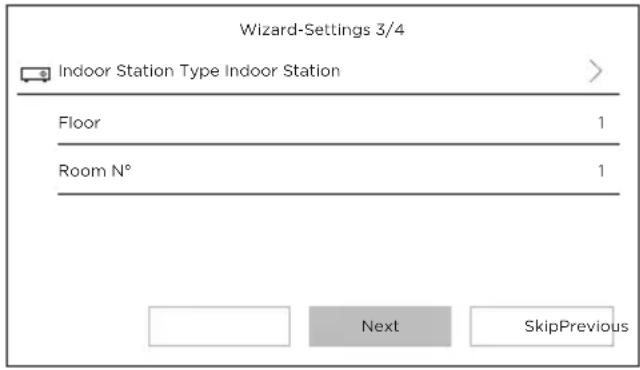
Step 4
You can find out the stage number and the unit number if you are installing multiple devices within a network.
This option is optional.
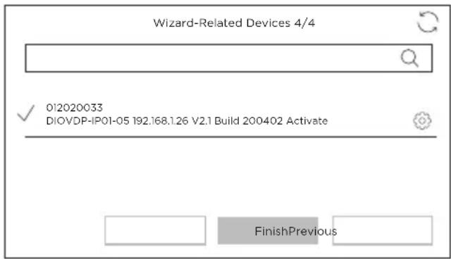
Step 5
Please wait 1 minute, until the outdoor unit is detected.
Attention! If the cables are correctly connected, the connection between the 2 units will be made automatically.
It is not necessary to enter a serial number.

If the connection does not work, please follow the help instructions provided via this link: https://www.youtube.com/watch?v=njqwbwLijlo

5.2 Connection to the wireless network
You do not have to connect your unit to the wireless network. It is only used to add it into the smartphone app for remote control purposes.
Select the settings menu from the home screen

Then select the Wi-Fi icon 📋 from the left-hand menu.
Select your network from the drop-down list
6. Installing the app
The application is available for Android and iOS.
Search for and install the “Guarding Vision” app on Android Play Store or Apple Store, depending on the model of your smartphone.
Open the application and create a user account by following the on-screen instructions.
6.1 Set-up via QR code
Select the settings menu from the home screen on your videophone monitor

Then select the configuration icon

Go to "Guarding Vision service parameters" to record the unit's QR code.
In the “Guarding Vision” app on your smartphone, select the “+” icon in the top right corner.
Select "Analyse code" from the drop-down menu.
Use your camera to scan the QR code on the videophone screen.
6.2 Manual set-up
Select the settings menu from the home screen on your videophone monitor
Then select the configuration icon


Go to "Information on the device" to record the serial number of the device.
In the “Guarding Vision” app on your smartphone, select the “+” icon in the top right corner.
Select "Add manually" from the drop-down menu.
Enter the serial number shown on the screen of your videophone.
Note:
The default password for your device is 123456
The default verification code for your device is ABCDEF
7. Special features of the videophone
7.1 In case of absence
With the «automatic answer» option, the videophone informs the visitor that it is busy, and gives him the possibility to leave a voice message.
8 Specifications
| General |
| Intercom type 2 wires - hands-free | |
| Operating temperatures -40 - +55°C | |
| Storage temperature -40 - +55°C | |
| Cable length and cross-section from 0 to 100 m / section: 1.5 mm2 | |
| Protection type (exterior unit) IP65 | |
| |
| Specifications |
| Adapter brand HOIOTO | |
| Adapter model number ADS-40FSI-19 24036EPG | |
| Input voltage 24DC | |
| Input AC frequency 100-240V - 50-60Hz | |
| Output voltage 24,0V DC | |
| Output current 1,5A | |
| Output power 36W | |
| Efficiency at medium active mode 89,9% | |
| Efficiency at low load (10%) 84,7% | |
| Power consumption at no load 0,07W | |
| Power consumption | Exterior unit < 10W ; Interior unit < 8W |
| Number of melodies | 3 |
| Talk time | From 90s to 120s |
| Audio frequency | 500. ~ 8k. Hz |
| Screen type | 7" TFT LCD touchscreen |
| Screen resolution | 1024 X 600 Pixels |
| Camera type 2MP Colour CMOS | |
| Camera resolution 1920 X 1080 Pixels | |
| Door opening 12.V - 1A max (1-5 seconds) | |
| Gate opening Contact sec NO/NC (1 second) | |
| WiFi encryption WPA-PSK/WPA2-PSK | |
| Security AES128 | |
| Protocols TCP/IP, RTSP, WIFI | |
| Infrared High power LED con ICR | |
| Infrared distance 3 meters | |
| Max eirp 0,07W | |
| Outdoor unit weight 1044g | |
| Indoor unit weight 624g | |

Direct current (DC)

Alternating current (AC)

For indoor use only

Class II equipment

Polarity of DC power connector

Caution

Operating instructions
Don't throw batteries or out of order products with the household waste (garbage). The dangerous substances that they are likely to include may harm health or the environment. Make your retailer take back these products or use the selective collect of garbage proposed by your city.

Hereby, Chacon, declares that the radio equipment type '34895' is in compliance with the Directive RED 2014/53/EU.
The full test of the EU declaration of conformity is available at the following Internet address: http://chacon.com/conformity
9. Support
www.chacon.com/support
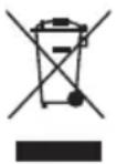
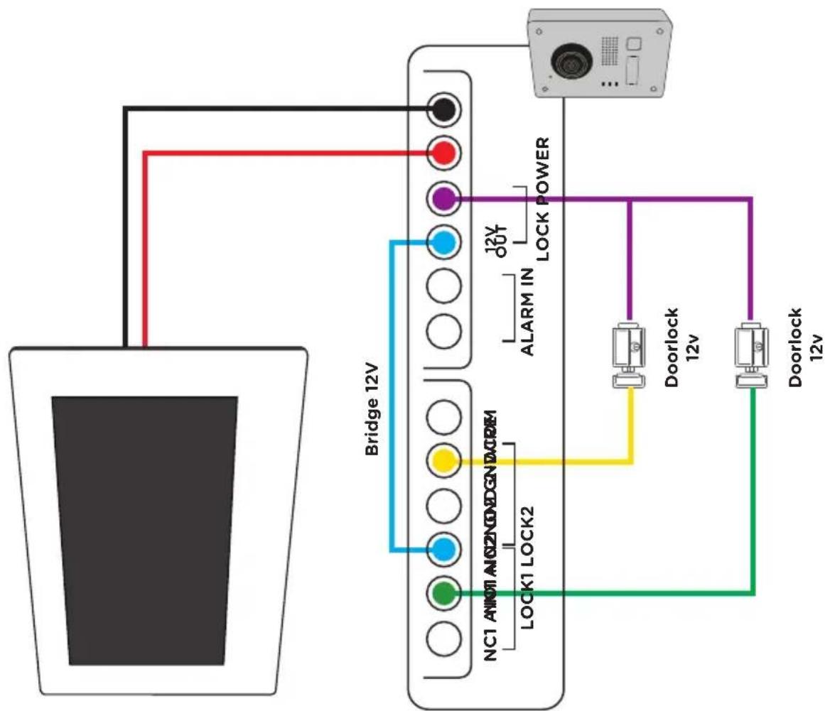
Diagram Connection 2 Wires: 2 Units Diagram Connection 2 Wires: Lock 12V +
Outside Gate
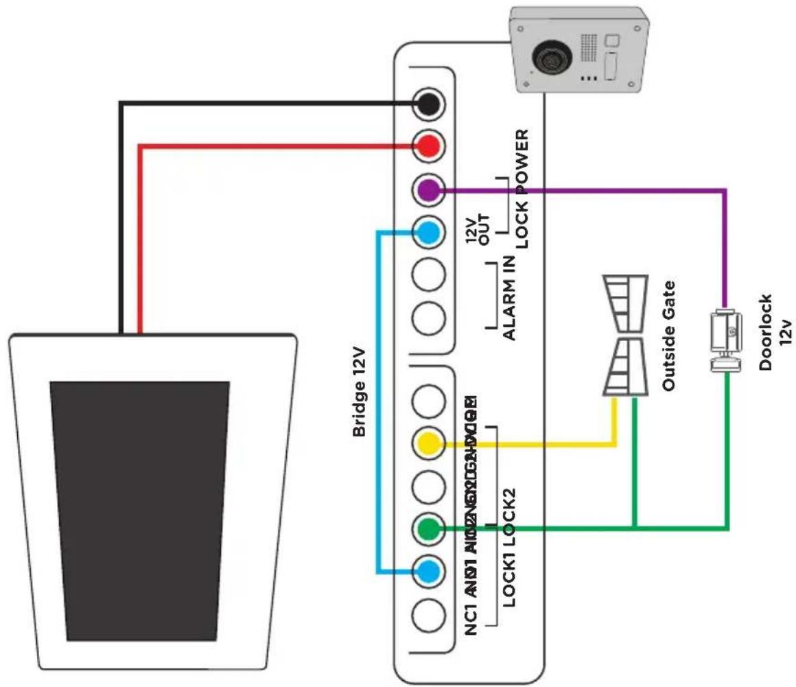
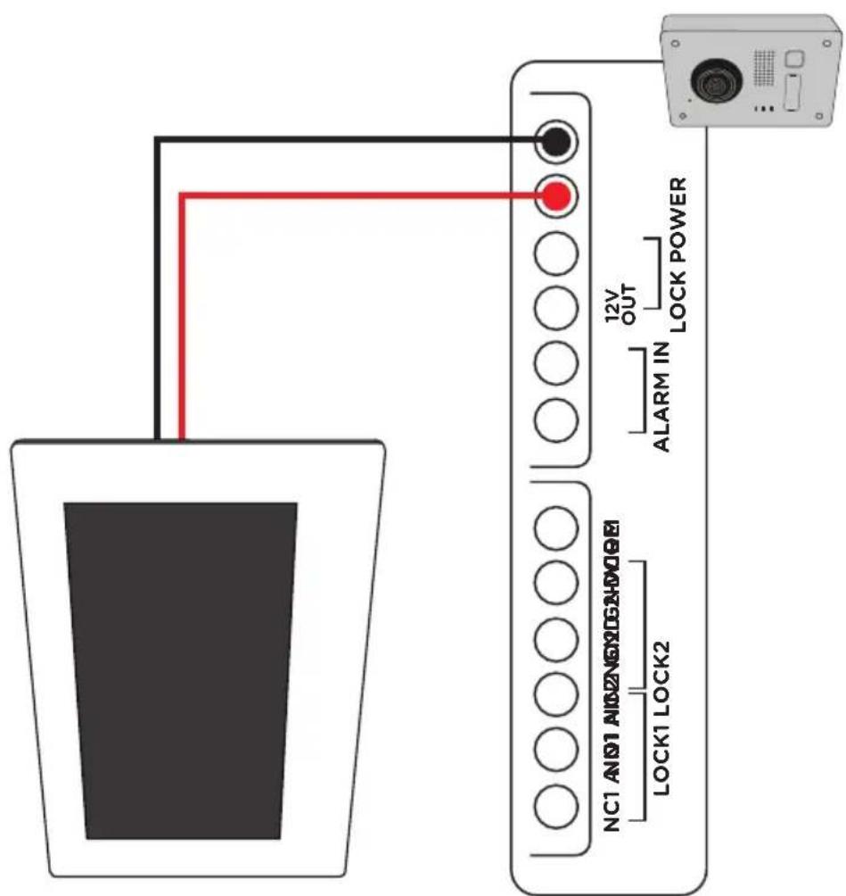
Diagram Connection 2 Wires: 2 Lock 12V/DC Diagram Connection 2 Wires: 2 Outside
Gate
(For further connections, ask a professional for advice).
NOTES