KPAC - Pump HAYWARD - Free user manual and instructions
Find the device manual for free KPAC HAYWARD in PDF.

| Product type | Heat pump for pool |
| Model | KPAC (HP5091/5111/5151/5181 series) |
| Dimensions (L x W x H) | 1003 x 418 x 605 mm (HP5091DT3HA model) |
| Weight | 44 kg (HP5091/5111) - 70 kg (HP5181) |
| Power supply | 230 V ~ 50 Hz, single-phase |
| Refrigerant | R32 (charge 0.430 to 0.670 kg depending on model) |
| Heating capacity (min-max) | 2.46 – 9.17 kW (condition A) |
| COP (max-min) | 14.37 – 6.32 (condition A) |
| Outdoor temperature range (heating) | -7 °C to +35 °C |
| Water temperature range | +12 °C to +32 °C (heating) |
| Nominal water flow rate | 4.00 to 7.70 m³/h depending on model |
| Hydraulic connection | 50 mm (PVC) |
| Sound pressure level at 1 m | 50.2 to 54.0 dB(A) depending on model |
| Touch screen | Yes, with temperature display and settings |
| Silent mode | Yes, programmable by timer |
| Anti-freeze protection | Yes, two levels (E07, E19, E29) |
| Maintenance | Annual evaporator cleaning, inspection of cables and connections |
| Spare parts | Available (see list in the manual appendix) |
| Warranty | 2 years (excluding wear parts and frost damage) |
Frequently Asked Questions - KPAC HAYWARD
User questions about KPAC HAYWARD
0 question about this device. Answer the ones you know or ask your own.
Ask a new question about this device
Download the instructions for your Pump in PDF format for free! Find your manual KPAC - HAYWARD and take your electronic device back in hand. On this page are published all the documents necessary for the use of your device. KPAC by HAYWARD.
USER MANUAL KPAC HAYWARD
3.3 Raccordement hydraulique
Activation / Désactivation

K2:CONTACT SEC MAX.16A
FS: DETECTEUR PRESENCE D'EAU ET: SONDE TEMPERATURE REFOUULEMENT
HP: PRESSOSTAT HAUTE PRESSION

IT:SONDE DE TEMPERATURE ENTREE D'EAU
6. ANNEXES (suite)
HP5151DT3HA / HP5181DT3HA
LEGENDE
AT:SONDE DE TEMPERATURE D'AIR
LP: PRESSOSTAT BASSE PRESSION
COMP: COMPRESSEUR OT: SONDE DE TEMPERATURE SORTIE D'EAU
CT:SONDE TEMPERATURE ÉVAPORATEUR
SUT: SONDE DE TEMPERATURE D'ASPIRATION
EEV:DETENDEUR ÉLECTRONIQUE 4V: VANNE 4 VOIES
FM:MOTEUR VENTILATEUR
K2: CONTACT SEC MAX. 16 A
FS: DETECTEUR PRESENCE D'EAU ET: SONDE TEMPERATURE REFOULEMENT
HP: PRESSOSTAT HAUTE PRESSION

IT:SONDE DE TEMPERATURE ENTREE D'EAU
6. ANNEXES (suite)
6.2 Raccordements priorité chauffage Pompe Monophasé
CONDITIONS DE GARANTIE
2.1 Heat pump technical data 5
2.2 Operating range 6
2.3 Dimensions 7
3. INSTALLATION AND CONNECTION 8
3.1 Functional Diagram 8
3.2 Heat pump unit 8
3.3 Hydraulic connection 10
3.4 Electrical connection 11
3.5 Initial start-up 12
3.6 Water flow setting 14
4. USER INTERFACE 15
4.1 General presentation 15
4.2 Timer function settings 17
4.3 Setting the On/Off timers 18
4.4 Adjust setpoint 20
4.5 Locking and unlocking the touch screen 21
4.6 SILENT function settings 22
5. MAINTENANCE AND WINTERISING 25
5.1 Maintenance 25
5.2 Winterising 25
6. APPENDIX 26
6.1 Electrical diagrams 26
6.2 Heating priority wiring for monophasic pump 28
6.3 Exploded view and spare parts 30
6.4 Troubleshooting guide 34
6.5 Warranty 37
6.6 End of life of the device 37
1. GENERAL INSTRUCTIONS - SAFETY
Thank you for purchasing the Hayward heat pump for swimming pools. The Hayward FULL INVERTER heat pump has been designed to strict manufacturing standards meeting the highest levels of quality required.
Hayward heat pumps offer you exceptional performance throughout your bathing season by adapting wattage, power usage and noise levels to the heating requirements of your swimming pool thanks to FULL INVERTER control logic.

Read the instructions in this manual carefully before using the device.
This manual includes all the necessary information for installation, trouble-shooting and maintenance.
Read this manual carefully before opening the unit or doing any maintenance work on it. The manufacturer of this product shall on no account accept any liability for injury to a user or damage to the unit further to any errors made during installation, trouble-shooting or unnecessary maintenance. It is particularly important to follow the instructions given in this manual at all times.
After having read this manual, keep it for future usage.
Authorised personnel
- The installation, electrical connections, maintenance and repairs of the device must be carried out by an accredited professional in accordance with the regulatory texts and the rules of the art in effect in the country where the device is installed (see § 3.4).
For any intervention on the cooling circuit, the professional must hold a certificate of competence in handling refrigerants.
For France:
- Low-voltage electrical installation according to NF-C 15-100.
- Legislation on the handling of refrigerants: Decree 2007/737 and its implementation orders.
1. GENERAL INSTRUCTIONS - SAFETY (continued)
This product contains refrigerant gas R32

This device contains R32.
Never use a refrigerant other than R32. Any other gaseous body mixed with R32 could cause abnormally high pressure and lead to a failure or pipes bursting and injuring people.
During repairs or maintenance operations, use copper tubes that comply with Standard NF EN 12375-1 and with European Pressure Equipment Directive 97/23/EC.
As the heat pump is pressurized, never pierce the pipes or attempt any brazing. There is a risk of explosion.
Never expose the device to flames, sparks or other sources of ignition. It could explode and cause serious or even fatal injuries.
To detect refrigerant leaks: do not use a halide lamp or any other detector that uses an open flame. Do not use potential sources of ignition under any circumstances.
This product contains fluorinated greenhouse gases regulated by the Kyoto protocol. Do not release these gases into the atmosphere.
GWP(1) value: 675, based in the 4th report of the IPCC.
Security group: A2L.
The quantity of refrigerant, based on the F-Gas regulation no. 517/2014, is stated on the unit's rating plate.
Any intervention on the cooling circuit must be carried out by an accredited professional as mentioned hereinabove.
Periodic inspections for leaks of refrigerant may be required by European or local legislation. Please contact your local distributor for more information.
- Warning, refrigerants can be odourless.
- Do not pierce or heat the pipes, risk of explosion and serious burns.
- Do not use a method for accelerating the defrosting or cleaning process other than those recommended by the manufacturer.
- The device must be stored in a room that does not contain any source of ignition operating on a permanent basis (for example, open flames, gas device or electric radiator that is operating).
(1) Global warming potential
1. GENERAL INSTRUCTIONS - SAFETY (continued)
Installation conditions
- This heat pump is designed exclusively to heat swimming pool water; do not use this equipment for any other purpose.
- Do not attempt to install this device by yourself.
- If you detect a fault or any abnormal situation, do not install the heat pump and contact your dealer immediately.
- If kept in storage, the heat pump should be kept in a well-ventilated room with a floor area of more than A_(m^2) as calculated by the following formula: A_ = (M / (2.5 × 0.22759 × h0))^2 . M is the quantity of refrigerant in the device in kg, and h0 is the storage height. If stored no the floor, h0 = 0.6 m.
- This product was designed exclusively for domestic use and installation outdoors. The air that escapes from the product must be able to flow freely and must not be used for other purposes such as heating or cooling a room or building.
- Check the power cable. If the power cable is damaged, it has to be replaced by the manufacturer, its after-sales service or by a qualified and authorised person.
- Grounding connection of the device and its continuity are mandatory. The ground wire has to be longer than the other wires in order to prevent the risks of electric shock in the event the cable is pulled out. The electrical installation must be equipped with a differential protection of 30mA (see 3.4 ).
- Make sure the support provided for the unit is strong enough to bear the weight of the unit.
- Failure to comply with recommendations will invalidate the warranty.
Instructions for servicing - maintenance
Maintenance operations must be carried out once per year in order to guarantee the longevity and the good working condition of the heat pump.
- Maintenance and the different operations must be carried out at the recommended times and frequencies as specified in this manual.
- Only use genuine spare parts.
- Check the power cable. If the power cable is damaged, it has to be replaced by the manufacturer, its after-sales service or by a qualified and authorised person.
- Verify the grounding connection of the device and its continuity.
- Clean the coil with the help of a soft brush or jet of air or water. Warning, never use a high pressure cleaner.
1. GENERAL INSTRUCTIONS - SAFETY (continued)
- Verify that the drains flow well.
- Verify the tightening of the hydraulic and electrical connections
- Verify the hydraulic sealing of the condenser.
- Have the leak-tightness of the cooling circuit to the leak detector checked by an accredited professional.

Before any maintenance operation, the heating pump must be disconnected from any electrical current source. The maintenance operations must only be carried out by personnel that is qualified and authorised to handle liquid refrigerants.
Instructions for winterising
- Put the heat pump in "OFF" mode.
- Cut the power supply to the heat pump.
- Empty the condenser with the help of the drain to avoid any risk of deterioration. (high risk of freezing).
- Close the by-pass valve and unscrew the entry/exit connection unions.
- Eliminate the maximum amount of residual stagnant water from the condenser with the help of an air gun.
- Close the water entry and exit areas of the heating pump to avoid introducing foreign bodies.
- Cover the heating pump with a dedicated winterising case.

Any damage caused by poor winterising maintenance will lead to cancellation of the warranty.
Conditions for use
This device can be used by children aged 8 years and over as well as by persons who have reduced, physical, sensory or mental capacities, or who lack experience or knowledge, if they are correctly monitored or if instructions pertaining to the use of the device in complete safety have been given to them and the risks incurred are understood.
Children must not play with the device.
Cleaning and maintenance by the user must not be carried out by children without surveillance.
2. TECHNICAL SPECIFICATIONS
2.1 Heat pump technical data
| Models FULL INVERTER HP5091DT3HA | HP5111DT3HA HP51 | 1DT3HA HP51 | 1DT3HA | ||
| Supply voltage V | 220V-240V ~/1ph/50Hz | ||||
| Refrigerant / R32 | |||||
| Load kg 0.430 0.450 0.60 0.670 | |||||
| Mass in teqCO2 | / 0.29 | 0.30 | 0.41 | 0.45 | |
| Leak check frequency | / | No specific frequency, but an annual check is recommended | |||
| Min--Max heating capacity(a) | kW | 2.46 -- 9.17 | 2.36 -- 11.45 | 3.31 -- 15.90 | 3.2 -- 18.15 |
| Min--Max electric input power(a) | kW | 0.17 -- 1.45 | 0.17 -- 1.80 | 0.27 -- 2.84 | 0.22 -- 3.13 |
| Min--Max continuous current rating(a) | A | 1.17 -- 6.42 | 1.19 -- 7.85 | 1.37 -- 12.35 | 1.45 -- 13.58 |
| Max--Min continuous power (COP)(a) | / | 14.37 -- 6.32 | 13.88 -- 6.35 | 12.26 -- 5.59 | 14.34 -- 5.80 |
| Min--Max heating capacity(b) | kW | 1.75 -- 7.05 | 1.56 -- 8.00 | 3.05 -- 12.40 | 2.86 -- 14.11 |
| Min--Max electric input power(b) | kW | 0.27 -- 1.51 | 0.279 -- 1.74 | 0.42 -- 2.65 | 0.43 -- 2.99 |
| Max--Min continuous power (COP)(b) | / | 6.40 -- 4.65 | 5.60 -- 4.80 | 7.26 -- 4.68 | 6.63 -- 4.71 |
| Maximum continuous current | A | 8.40 | 9.50 | 14 | 15.9 |
| Fuse rating | aM | 10 | 12 | 16 | 20 |
| Circuit-breaker curve D | D | 10 | 12 | 16 | 20 |
| Starting current | A | < maximum continuous current | |||
| Hydraulic connection | mm | 50 mm | |||
| Nominal water flow(a) | m³/h | 4.00 | 5.00 | 6.70 | 7.70 |
| Max. loss of head on water | kPa | 3.80 | 4.0 | 6.3 | 10 |
| Compressor | / | DC Inverter Panasonic | DC Inverter Mitsubishi | ||
| Type | / | Twin rotary | Twin rotary | ||
| Quantity | / | 1 | |||
| Coil resistance at 20°C | Ohm | 1.208 | 0.95 | ||
| Fan | / | Axial | |||
| Quantity | 1 | ||||
| Diameter | mm | 405 | 510 | ||
| Number of blades | / | 3 | |||
| Motor | / | DC Inverter | |||
| Quantity | / | 1 | |||
| Rotation speed | rpm | 400 -- 700 | 500 -- 850 | 300 -- 750 | 400 -- 750 |
| Silent mode speed | rpm | 400 | 500 | 300 | 400 |
| Sound pressure level at 1 meter | dB(A) | 50.2 | 53.9 | 50.8 | 54.0 |
| Sound pressure level at 10 meters | dB(A) | 32.8 | 34.2 | 33.8 | 37.25 |
| Unit's net dimensions (L-W-H) | mm | 1003 / 418 / 605 | 1048 / 437 / 768 | 1161 / 473 / 862 | |
| Weight | kg | 44 | 45 | 66 | 70 |
(a) Dry air 27^ - Relative humidity 78% - Water inlet temperature 26^ .
(b) Dry air 15^ - Relative humidity 71% - Water inlet temperature 26^
2. TECHNICAL SPECIFICATIONS (continued)
2.2 Operating range
Use the swimming pool heat pump unit within the following ranges of temperature and humidity to ensure safe and efficient operation.
| Heating mode | Cooling mode | |
| Outside temperature -7°C – +35°C +7°C – +43°C | ||
| Water temperature +12°C – +32°C +8°C – +40°C | ||
| Relative humidity < 80% < 80% | ||
| Setting range from the set point +15°C – +32°C +8°C – +32°C |

If the temperature or humidity does not correspond to these conditions, the security measures could be activated and the swimming pool heat pump unit may no longer work.

The maximum heating temperature is set at 32^ to prevent damage to the liners. Hayward cannot be held responsible if used at a temperature above +32^ .
2. TECHNICAL SPECIFICATIONS (continued)
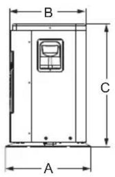
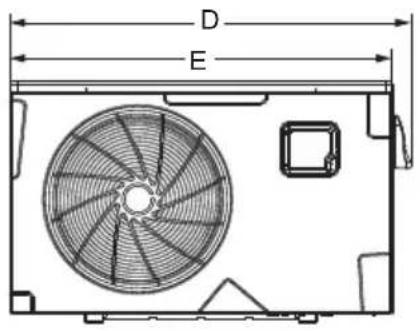
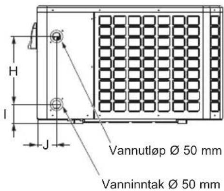
2.3 Dimensions
Models:
HP5091DT3HA / HP5111DT3HA / HP5151DT3HA / HP5181DT3HA
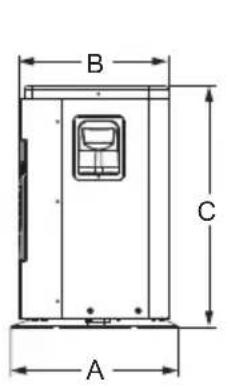
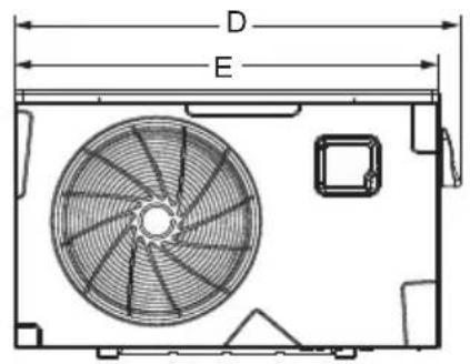
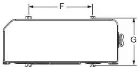
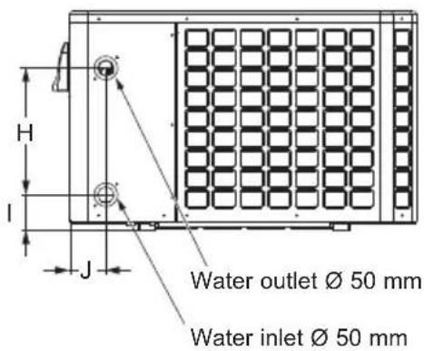
Unit: mm
| Size\Type | HP5091DT3HA / HP5111DT3HA | HP5151DT3HA | HP5181DT3HA |
| A 418 436 | 5 473 | ||
| B 374 418 | 451,5 | ||
| C 604,5 767 | 7,5 862 | ||
| D 1003 1047 | 7,5 1160,5 | ||
| E 956 1002 | 1115 | ||
| F | 535 615 | 790 | |
| G | 394,5 410 | 447 | |
| H 350 350 | 466 | ||
| I | 97,7 | 101,2 | 97,6 |
| J | 99,2 | 106,5 | 113,5 |
3. INSTALLATION AND CONNECTION
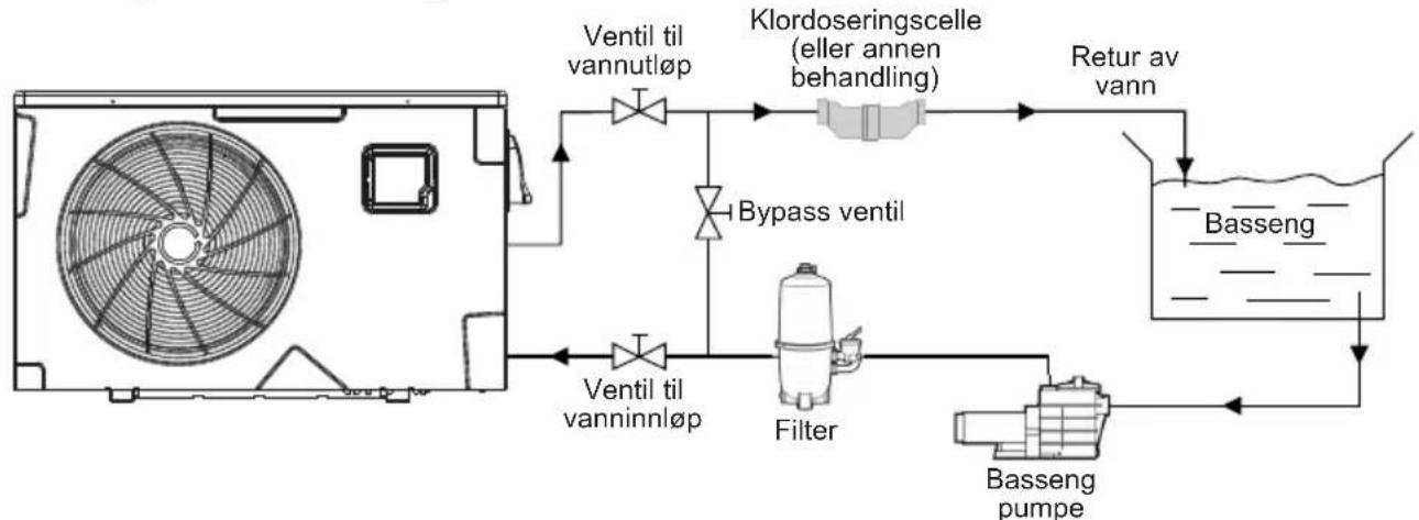
3.1 Functional Diagram
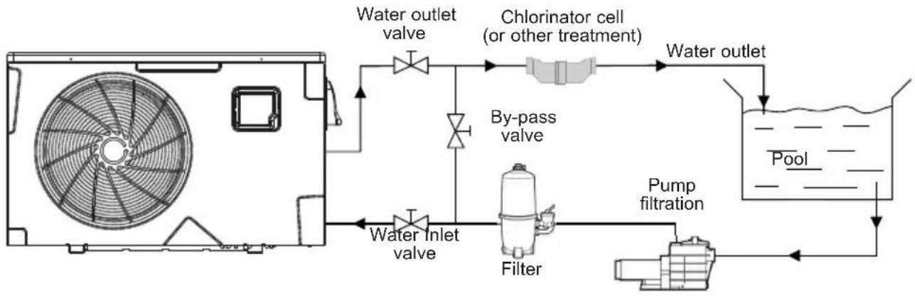
Note: The swimming pool heat pump unit is sold without any treatment or filtration equipment. The components presented in the diagram are spare parts to be supplied by the installer.
3.2 Heat pump unit

Place the heat pump outdoors and away from any enclosed technical space.
Choose a location that is preferably sunlit and sheltered from dominant winds.
The device must be perfectly accessible for later installation and maintenance work.
Placed under a shelter, the minimum required distances mentioned below must be respected in order to avoid any risk of air recirculation and a deficiency in the unit's overall performance.
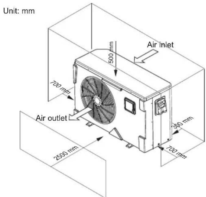
3. INSTALLATION AND CONNECTION (continued)

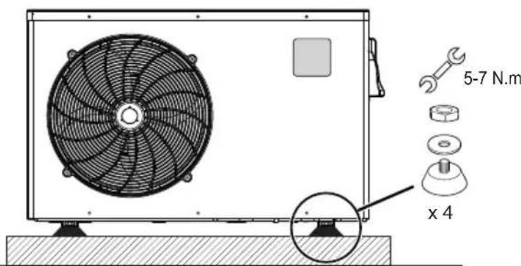
Do not position the device directly on the floor because this could cause problems.
Favour positioning on the ground on anti-vibration studs.
A wall bracket must not be used in conditions that can transmit vibrations.
Do not install the heat pump on a support that risks intensifying the unit's vibrations.
Do not install the heat pump anywhere liable to amplify its noise level or anywhere where its noise could disturb neighbours.
Do not use adhesives: the latter are not considered to be a reliable means of fastening.
Preferably, install the heat pump on a flat and dissociated cement block. Set up the unit on the supplied rubber bushing (fastenings and washers supplied).
Fasten the device, in compliance with the tightening indicated to avoid any risk of accident or damage to equipment and persons.
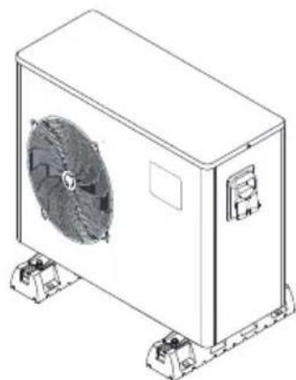
Another possibility: install the heat pump on rubber floor supports using suitable fastenings (not supplied).

The maximum installation distance between the unit and the swimming pool is 15 metres.
The total length of the piping to and from the unit is 30 metres.
Insulate both the above ground and buried hydraulic piping.
The heat pump must be installed at a minimum distance from the pool in compliance with NF C 15-100 (3.5 m from the water for France) or in compliance with installation standards applicable in other countries.
Do not install the heat pump close to a heat source.
For installation in snowy regions we recommend sheltering the machine to avoid snow accumulating on the evaporator.
3. INSTALLATION AND CONNECTION (continued)
3.3 Hydraulic connection
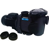
The unit is supplied with two 50~mm union connections. Connect the water inlet to the heat pump coming from the filtration group then connect the water outlet to the heat pump at the water conduit going to the pool (see diagram below).
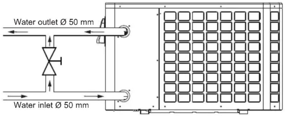
Install a by-pass valve between the heat pump entrance and exit.

If an automatic distributor or an electrolyser is used, it should be installed imperatively after the heat pump with the goal of protecting the titanium condenser against an elevated concentration of chemicals.

Be sure to install the by-pass valve and the supplied union connections at the water inlet and outlet level in order to simplify purging during the winter period and to facilitate access when disassembling for maintenance.
3. INSTALLATION AND CONNECTION (continued)
3.4 Electrical connection

Electrical installation and wiring for this equipment must be in conformity with local installation standards.
| F NF C15-100 GB BS7671:1992 | ||
| D DIN VDE 0100-702 EW EVHS-HD 384-7-702 | ||
| A ÖVE 8001-4-702 H MSZ 2364-702/1994/M SZ 10-553 1/1990 | ||
| E UNE 20460-7-702 1993, RECBT ITC-BT-31 2002 | M MSA HD 384-7-702.S2 | |
| IRL Wiring Rules + IS HD 384-7-702 PL PN-IEC 60364-7-702:1999 | ||
| I CEI 64-8/7 CZ CSN 33 2000 7-702 | ||
| LUX 384-7.702 S2 | SK | STN 33 2000-7-702 |
| NL NEN 1010-7-702 | SLO | SIST HD 384-7-702.S2 |
| P R$IUEE TR TS IEC 60364-7-702 | ||

Verify that the available electrical power supply and the network frequency correspond to the required operating current taking into account the appliance's specific location, and the current required to supply any other appliance connected to the same circuit.
HP5091DT3HA / HP5111DT3HA / HP5151DT3HA / HP5181DT3HA 230V + / - 10% 50 Hz 1 Phase
See the corresponding wiring diagram in the appendix.
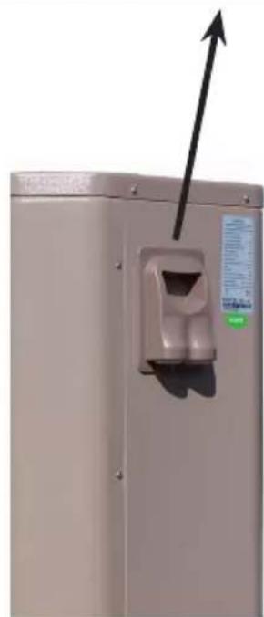
The connection box is located on the right side of the unit. Three connections are designed for the power supply and two are for controlling the filter pump (Enslavement).
3. INSTALLATION AND CONNECTION (continued)

Never use an electrical plug for the power supply.
The electrical power supply must have, in a suitable manner, an omnipolar protection device of the D -curve circuit breaker type as well as a 30mA protection differential circuit breaker (see following table).
| Models HP5091DT3HA HP5111 | DT3HA HP5151 | DT3HA HP5181 | DT3HA | ||
| Power supply | V/Ph/Hz | 230V~ 50Hz | 230V~ 50Hz | 230V~ 50Hz | 230V~ 50Hz |
| Curve D circuit breaker | A 8 D 10 | D 16 D 20 D | |||
| Cable section | mm² | 3G 2,5 3G | 2,5 3G 2,5 | 3G 4 | |

Use an RO 2V/R 2V or equivalent power cord.

The cables sections are given for a maximum length of 25m . They must however be checked and adjusted according to the installation conditions.

Always shut down the main power supply before opening the electrical control box.
After a cut-off of the power supply, wait 10 minutes before accessing the active internal parts of the equipment (power stored in the capacitors).
3.5 Initial start-up
Start-up procedure - After installation is complete, follow these steps:
1) Rotate the fans by hand to verify that they can turn freely by hand, and that the turbine is correctly affixed to the motor shaft.
2) Ensure that the unit is connected correctly to the main power supply (see the wiring diagram in the appendix).
3) Activate the filtration pump.
4) Verify that all water valves are open and that the water flows toward the unit before switching on the heating or cooling mode.
5) Verify that the drainage hose is correctly affixed and that it causes no obstructions.
6) Activate the unit power supply, then press the On/Off button on the control panel.
3. INSTALLATION AND CONNECTION (continued)
7) Make sure the alarm or lock symbols are not displayed. If need be, see the trouble-shooting guide (see § 6.4).
8) Set the water flow using the by-pass valve (see § 3.6 and 2.1), as provided for by each model, to obtain an Entry/Exit temperature of 2^ .
9) After running for several minutes, verify that the air exiting the unit is cool (between 5 and 10^ ).
10) With the unit operating, turn off the filter pump. The unit should automatically turn off and display error code E03 (See § 6.4).
11) Allow the unit and the pool pump to run 24 hours per day until the desired water temperature has been reached. When the set water inlet temperature is reached, the unit will turn off. It will automatically restart (as long as the pool pump is running) if the pool temperature is at least 0.5^ below the set temperature.
Water flow switch - The unit is equipped with a flow switch that turns on the heat pump when the pool filtration pump is running, and deactivates it when the filtration pump is out of order. If the water is low, the E03 alarm code will appear on the regulator (See § 6.4).
Time delay - The unit is equipped with a time delay of 3 minutes in order to protect the control circuit components, to eliminate restart cycling and contactor chatter. Thanks to this time delay, the unit automatically restarts approximately 3 minutes after each control circuit interruption. Even a brief power interruption will activate the restart time delay.
3. INSTALLATION AND CONNECTION (continued)
3.6 Water flow setting
With the water entry and exit valves being open, adjust the by-pass valve in order to obtain a difference of 2^ between the inflow and outflow temperature (see principle diagram 3.1 ). You can verify the switch by seeing the entry/exit temperatures directly on the control panel.
Water inlet temperature Water outlet temperature
Note: Opening the by-pass valve creates a weaker flow, which leads to an increase in T .
Closing the by-pass valve creates a stronger flow, which leads to a decrease in T .
4. USER INTERFACE
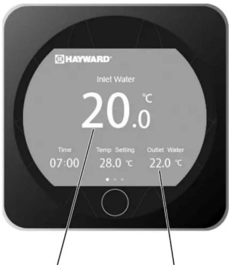
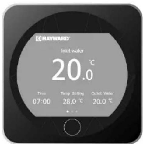
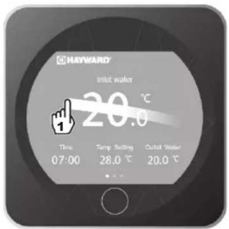
4.1 General presentation
The heat pump is equipped with a digital control panel with a touch screen, electronically connected and pre-set at the factory in heating mode.
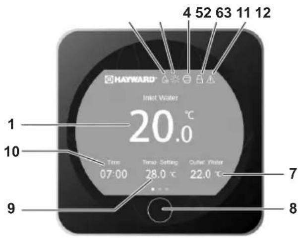
Legend
| 1 Water Input temperature |
| 2 Defrost mode |
| 3 Operating mode |
| 4 Compressor's ON indicator |
| 5 Lock screen |
| 6 Alarm |
| 7 Water Output temperature |
| 8 On/Off/Back |
| 9 Setpoint temperature |
| 10 Hour |
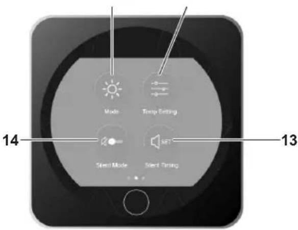
| 11 C | operating mode selection |
| 12 A | adjust setpoint |
| 13 S | setting silence mode timer |
| 14 A | activate silent mode |
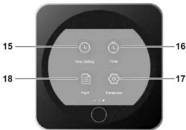
| 15 S | set date and time |
| 16 S | set On/Off timers |
| 17 A | access Advanced Settings |
| 18 A | access list of faults |
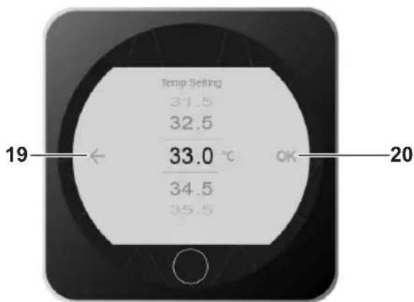
| 19 B | back (changes not confirmed) |
| 20 C | Confirm |
4. USER INTERFACE (continued)
OFF mode
When the heat pump is idle (in standby mode), OFF is displayed as shown on the screen.
The black screen indicates that the heat pump is idle; settings can be adjusted in this mode.
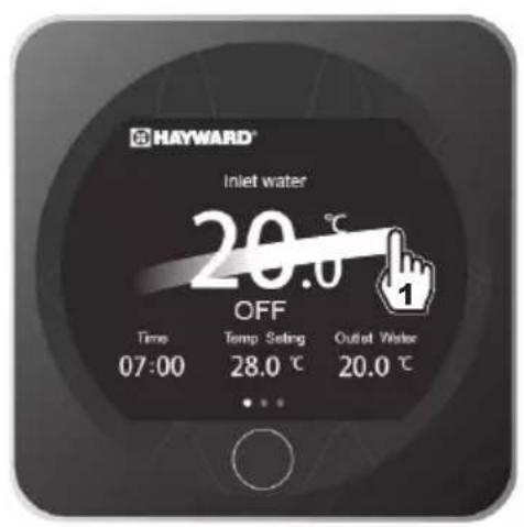
ON mode
When the heat pump is running or priming (setpoint reached), the screen turns blue.
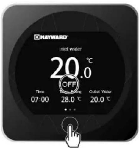
To switch from OFF to ON mode and vice versa, press the button.
4. USER INTERFACE (continued)
4.2 Timer function settings
The date and time can be set either in ON or in OFF mode.


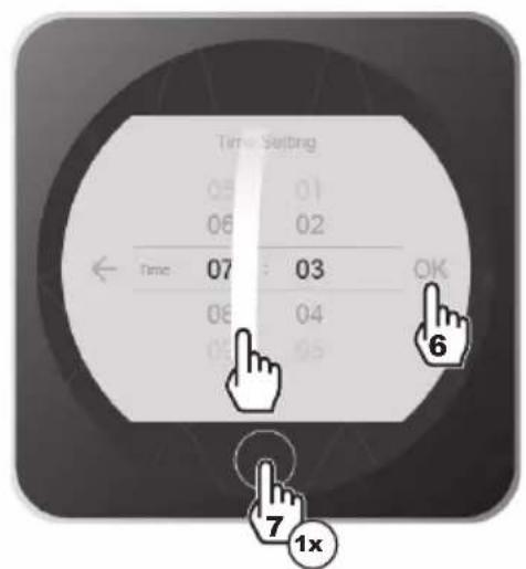
- Press 1 times on return to the main screen.
4. USER INTERFACE (continued)
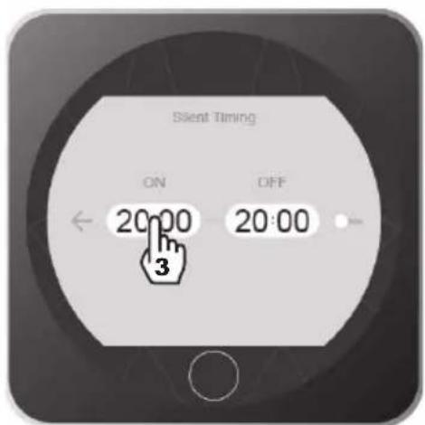
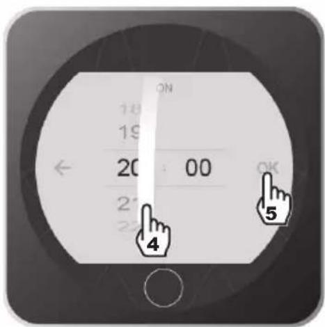
4.3 Setting the On/Off timers
Setting this function is necessary if you would like to run the heat pump for a shorter period than what is defined by the filtration clock. Therefore, you can program a deferred start and an anticipated stop or simply stop a certain timeframe from running (at night, for example).
It is possible to set one Start Timer and one Stop Timer.
The setting step is "hour to hour".


4. USER INTERFACE (continued)


Blue highlighting = Activated
Grey = Deactivated
- Press 2 times on return to the main screen.
4. USER INTERFACE (continued)
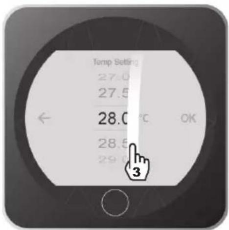
4.4 Adjust setpoint
The setpoint can be changed either in ON or in OFF mode with an accuracy of 0.5^ .


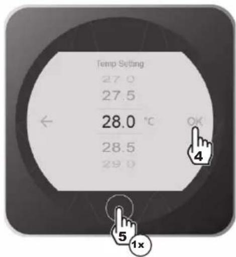
- Press 1 times on to return to the main screen.

It is recommended to never exceed 30^ to avoid alteration of the liners.
4. USER INTERFACE (continued)
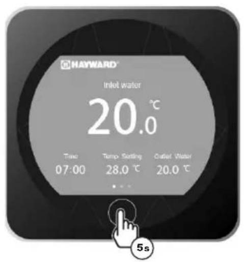
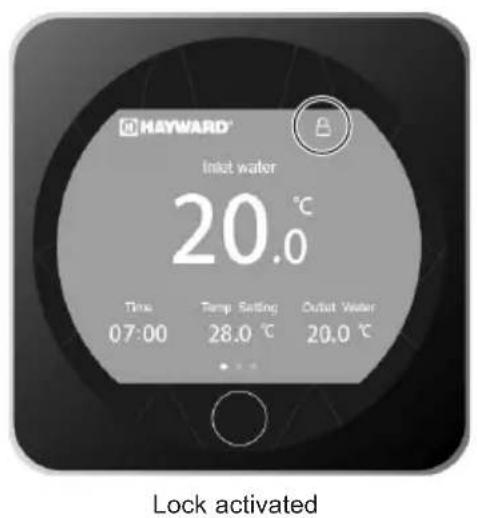
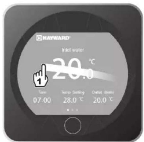
4.5 Locking and unlocking the touch screen
The screen can be locked or unlocked either in ON or in OFF mode.


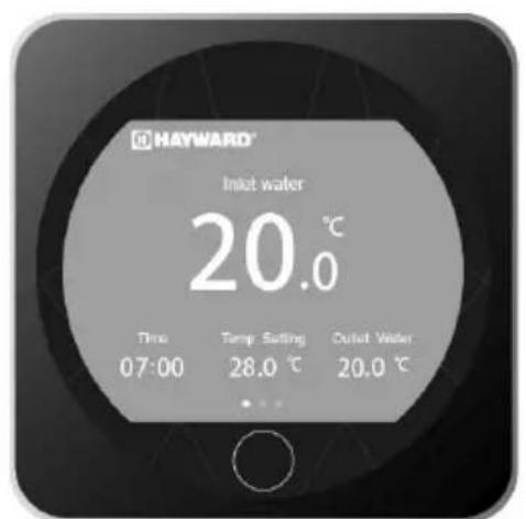
Lock deactivated
4. USER INTERFACE (continued)
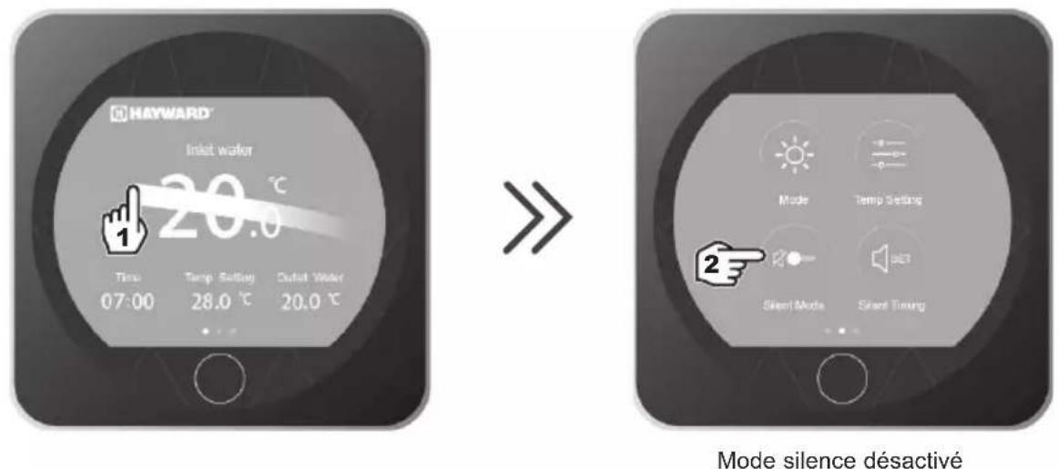
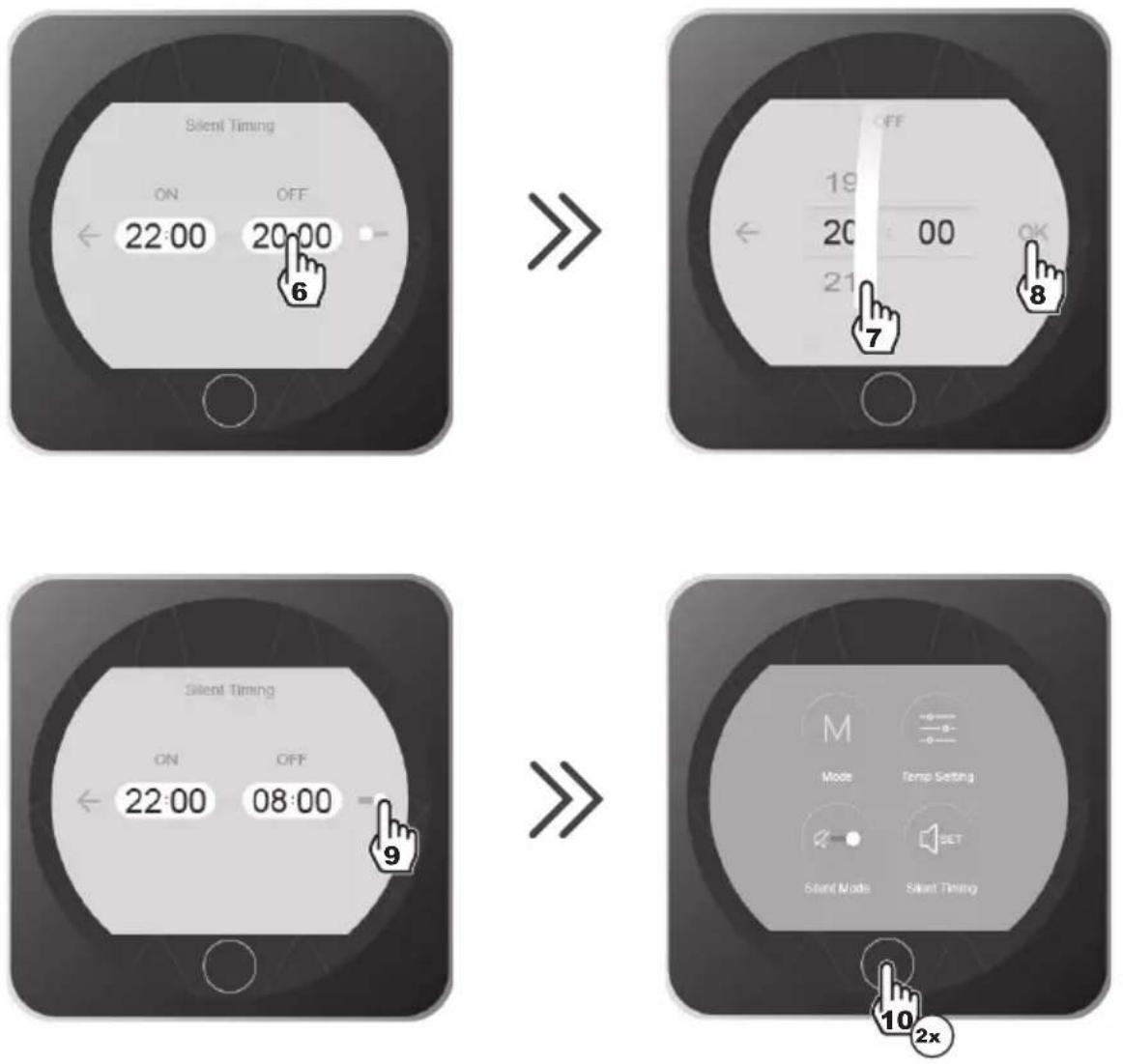
4.6 SILENT function settings
Silence mode enables the heat pump to be used in economic and very silent mode when the heating needs are low (maintaining the pool temperature or need for ultra-silent operation).
This function can be Activated/Deactivated manually or using a Timer.
Activation/Deactivation

Silent mode deactivated

Silent mode activated
- Press 1 times on to return to the main screen.
4. USER INTERFACE (continued)
Adjusting the SILENT mode Timer


4. INTERFACE UTILISATEUR (suite)
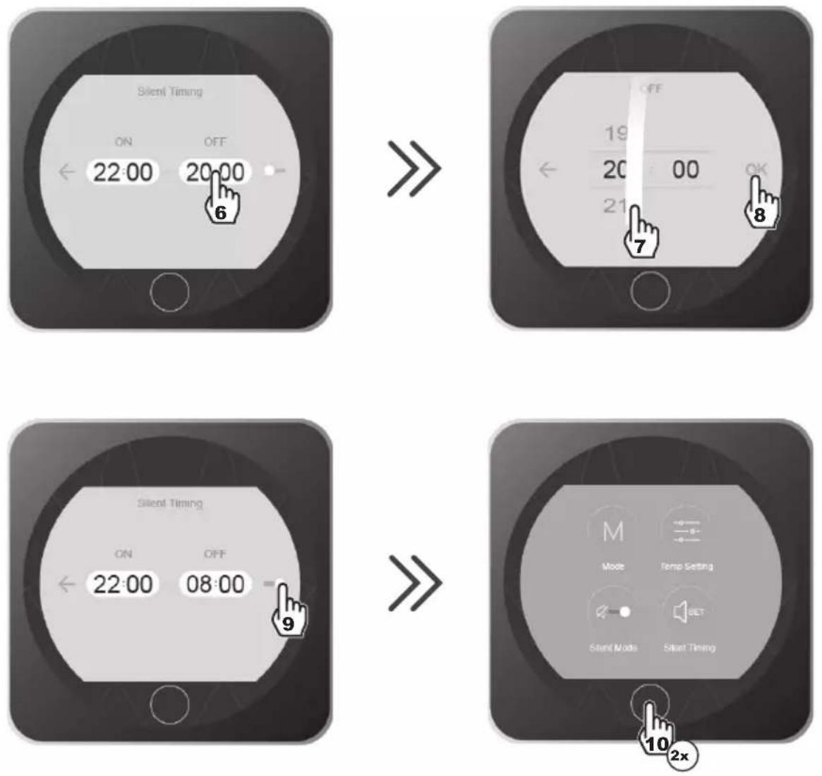
- Press 2 times on return to the main screen.

The setting step is "hour to hour". Once the Timer is activated, it is active 7 days a week.
5.1 Maintenance
These maintenance operations must be carried out once per year in order to guarantee the longevity and the good working condition of the heat pump.
- The maintenance and repairs of the device must be carried out by an accredited professional in accordance with the regulatory texts and the rules of the art in effect in the country where the device is installed (see § 3.4).
For any intervention on the cooling circuit, the professional must hold a certificate of competence in handling refrigerants. - Check the power cable. If the power cable is damaged, it has to be replaced by the manufacturer, its after-sales service or by a qualified and authorised person.
- Verify the grounding connection of the device and its continuity.
- Clean the coil with the help of a soft brush or jet of air or water. Warning, never use a high pressure cleaner.
- Verify that the drains flow well.
- Verify the tightening of the hydraulic and electrical connections
- Verify the hydraulic sealing of the condenser.
- Have the leak-tightness of the cooling circuit to the leak detector checked by an accredited professional.

Before any maintenance operation, the heating pump must be disconnected from any electrical current source. The maintenance operations must only be carried out by personnel that is qualified and authorised to handle liquid refrigerants.
5.2 Winterising
- Put the heat pump in "OFF" mode.
- Cut the power supply to the heat pump.
- Empty the condenser with the help of the drain to avoid any risk of deterioration. (high risk of freezing).
- Close the by-pass valve and unscrew the entry/exit connection unions.
- Eliminate the maximum amount of residual stagnant water from the condenser with the help of an air gun.
- Close the water entry and exit areas of the heating pump to avoid introducing foreign bodies.
- Cover the heating pump with a dedicated winterising case.

Any damage caused by poor winterising maintenance will lead to cancellation of the warranty.
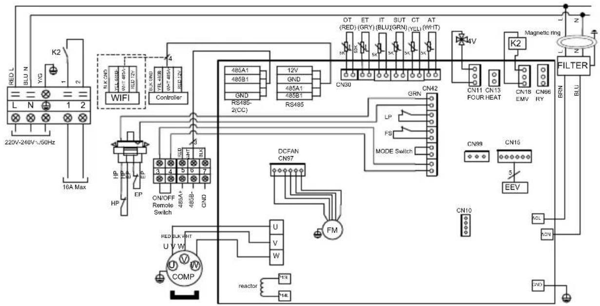
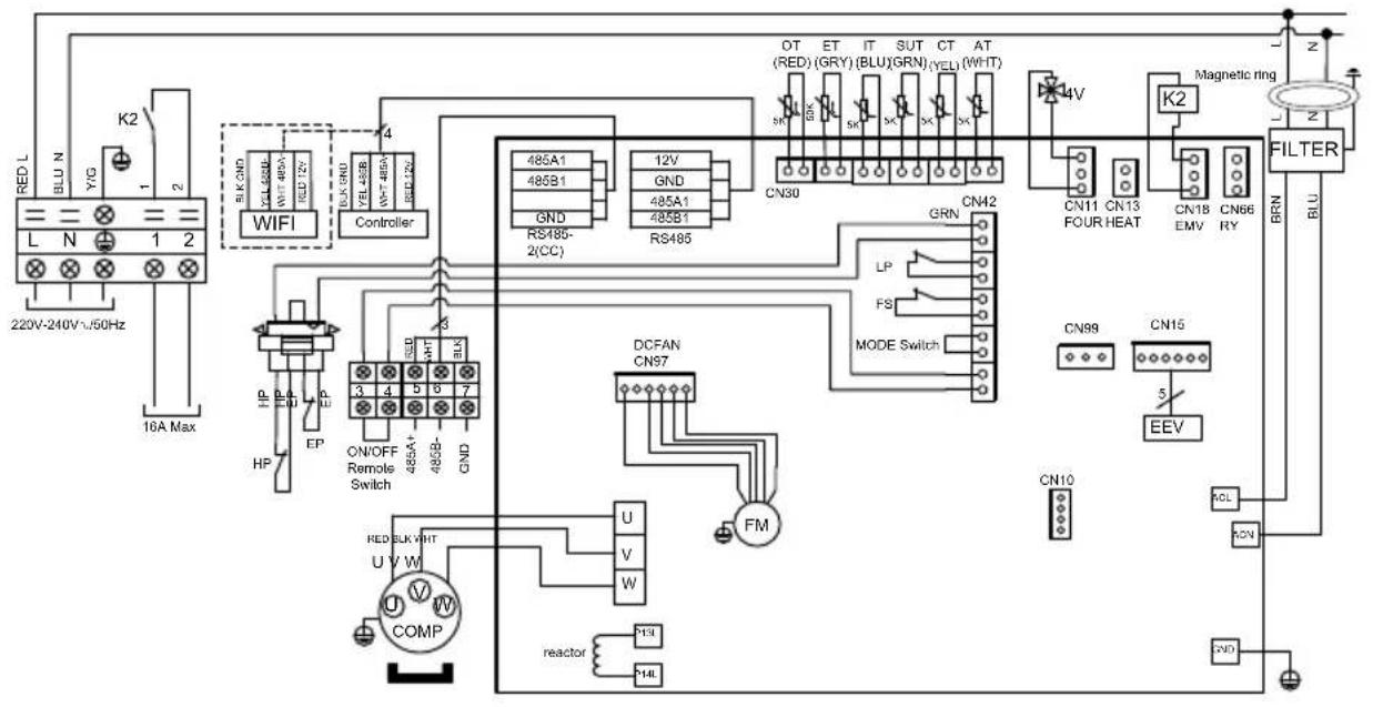
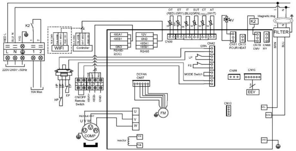
6.1 Electrical diagrams
HP5091DT3HA / HP5111DT3HA
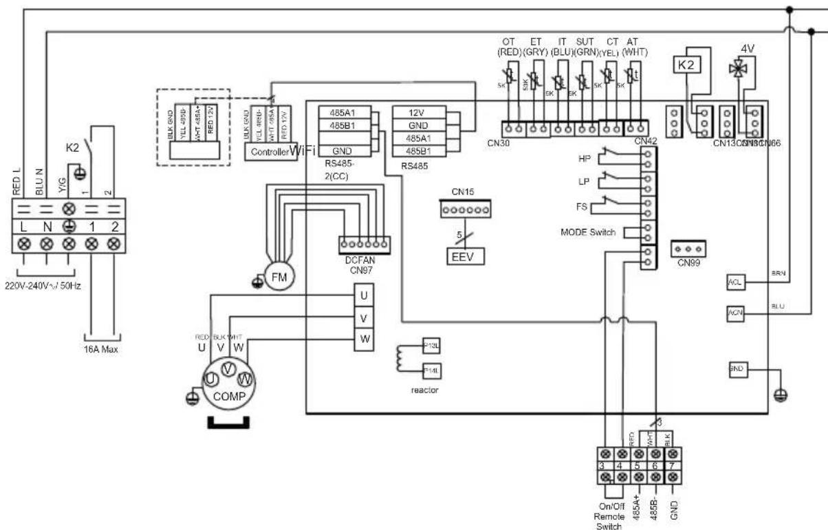
REMARKS
AT: AIR TEMPERATURE SENSOR
COMP: COMPRESSOR
CT: EVAPORATOR TEMPERATURE SENSOR
EEV: ELECTRONIC EXPANSION VALVE
FM:FAN MOTOR
FS: WATER FLOW SWITCH
HP: HIGH PRESSURE SWITCH
IT: WATER INLET TEMPERATURE SENSOR
LP: LOW PRESSURE SWITCH
OT: OUTLET WATER TEMPERATURE SENSOR
SUT: SUCTION TEMPERATURE SENSOR
4V: 4WAYS VALVE
K2: DRY CONTACT 16 A MAX
ET: DISCHARGE TEMPERATURE SENSOR
:OPTION
HP5151DT3HA / HP5181DT3HA
REMARKS
AT: AIR TEMPERATURE SENSOR
COMP: COMPRESSOR
CT: EVAPORATOR TEMPERATURE SENSOR
EEV: ELECTRONIC EXPANSION VALVE
FM:FAN MOTOR K2:DRY CONTACT 16 A MAX
FS: WATER FLOW SWITCH
HP: HIGH PRESSURE SWITCH
IT: WATER INLET TEMPERATURE SENSOR
LP: LOW PRESSURE SWITCH
OT: OUTLET WATER TEMPERATURE SENSOR
SUT: SUCTION TEMPERATURE SENSOR
4V: 4 WAYS VALVE
ET: DISCHARGE TEMPERATURE SENSOR

OPTION
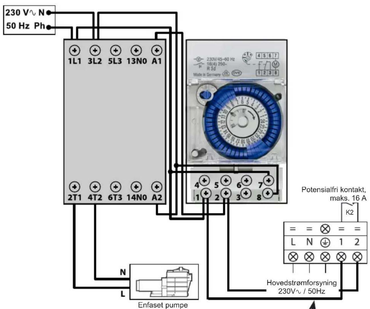
6. APPENDIX (continued)
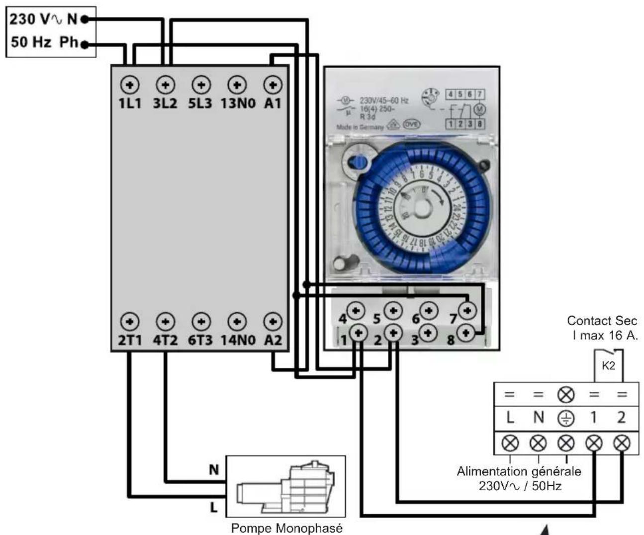
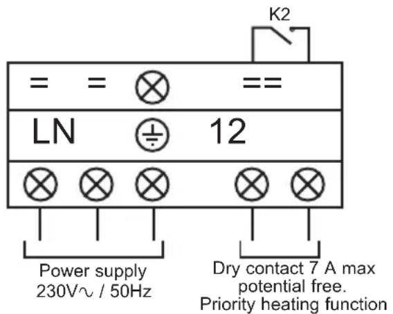
6.2 Heating priority wiring for monophasic pump
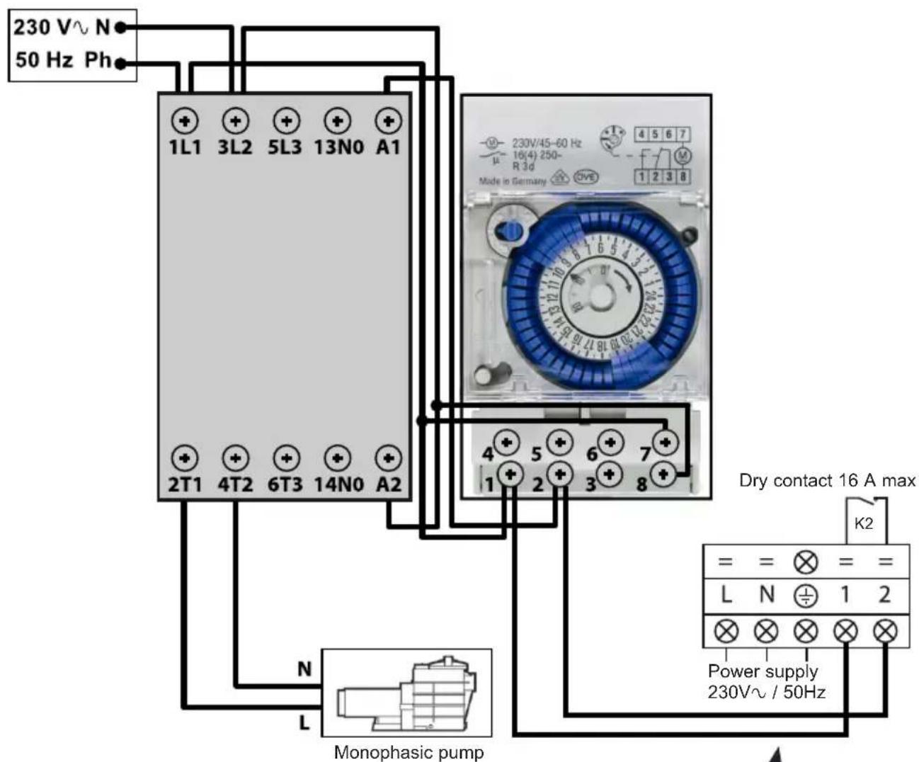
Terminals 1 and 2 deliver a potential-free dry contact, 230V /50Hz no polarity.
Wire terminals 1 and 2 as indicated in the diagram above, to activate the operation of the filtration pump in 2-minute cycles each hour if the temperature of the pool is lower than the set point.
! Never connect the power supply of the filtration pump directly to terminals 1 and 2.
Page left intentionally blank
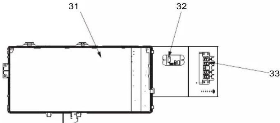
6. APPENDIX (continued)
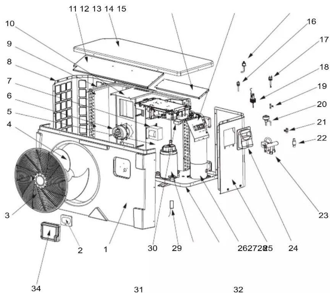
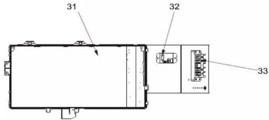
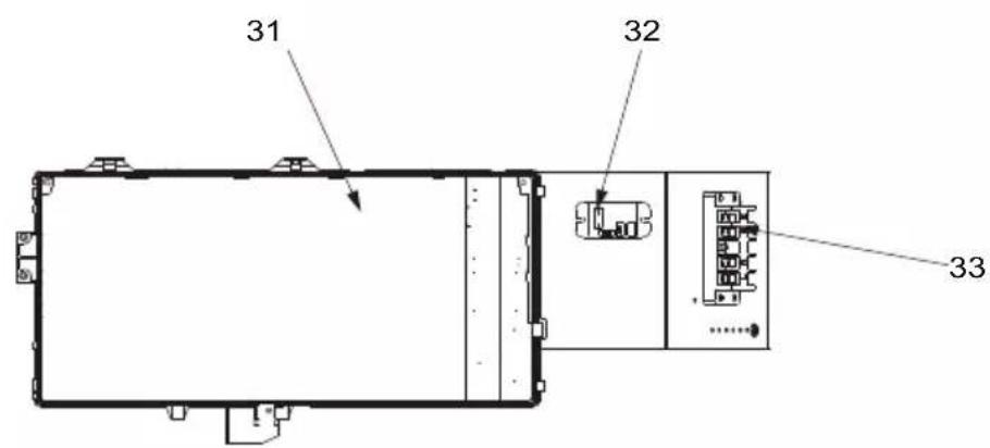
6.3 Exploded view and spare parts
HP5091DT3HA / HP5111DT3HA / HP5151DT3HA / HP5181DT3HA
6. APPENDIX (continued)
| Mark | Description Ref. | HP5091DT3HA | HP5111DT3HA | HP5151DT3HA | HP5181DT3HA | |
| 1 | Front panel | HWX80900843 | ✓ | ✓ | n/a n/a | |
| HWX80900844 | n/a n/a | ✓ | n/a | |||
| HWX80900850 | n/a | n/a n/a | ✓ | |||
| 2 | LED controller HWX72200070 | ✓✓ | ✓✓ | |||
| 3 | Fan protection grille | HWX80900375 | ✓ | ✓ | ✓ | n/a |
| HWX20000220369 | n/a n/a n/a | ✓ | ||||
| 4 | Fan blade | HWX301030000006 | ✓ | ✓ | n/a | n/a |
| HWX301030000001 | n/a n/a | ✓ | ✓ | |||
| 5 | / / / | / | / | |||
| 6 | DC Fan Motor | HWX80200018 | ✓ | ✓ | n/a n/a | |
| HWX20000330132 | n/a | n/a | ✓ | ✓ | ||
| 7 | 16 A 50 Hz 5 mH coil HWX82500020 | ✓ | ✓ | n/a n/a | ||
| 20 A 50 Hz 5.2 mH coil HWX82500021 | n/a n/a | ✓ | ✓ | |||
| 8 | Left panel | HWX80702123 | ✓ | ✓ | n/a n/a | |
| HWX80700244 | n/a | n/a | ✓ | n/a | ||
| HWX80702268 | n/a | n/a n/a | ✓ | |||
| 9 | Fin coil | HWX80600042 | ✓ | n/a n/a n/a | ||
| HWX80600043 | n/a | ✓ | n/a n/a | |||
| HWX80600044 | n/a | n/a | ✓ | n/a | ||
| HWX80600078 | n/a n/a n/a | ✓ | ||||
| 10 | Motor bracket | HWX80700218 | ✓ | ✓ | n/a n/a | |
| HWX80700248 | n/a n/a | ✓ | n/a | |||
| HWX80700329 | n/a n/a n/a | ✓ | ||||
| 11 | / / | / / / | ||||
| 12 | Upper front panel | HWX80900055 | ✓ | ✓ | n/a n/a | |
| HWX301090200806 | n/a n/a | ✓ | n/a | |||
| HWX80900076 | n/a | n/a n/a | ✓ | |||
| 13 | / / / / / | |||||
| 14 | / / / / / | |||||
| 15 | Low pressure switch NO 0.30 MPa / 0.15 MPa | HWX20000360157 | ✓ | ✓✓ | ✓ | |
| 16 | Pressure Tap 40 mm-1/2" | HWX20000140150 | ✓✓ | ✓✓ | ||
| 17 | High pressure switch NC 3.2 MPa/4.4 MPa | HWX20013605 | ✓✓ | ✓✓ | ||
| 18 | Water flow detector | HWX83000068 | ✓✓ | ✓✓ | ||
| 19 | T connector Ø 6.5-2 x Ø 6.5(T) x 0.75 | HWX20001460 | ✓✓ | ✓✓ | ||
| 20 | Electronic expansion valve | HWX8100011 | ✓ | ✓ | n/a n/a | |
| HWX8100013 | n/a n/a | ✓ | ✓ | |||
| 21 | T connector Ø 9.52-2 x Ø 6.35(T) x 1.0 | HWX30403000002 | ✓ | ✓✓ | ✓ | |
| 22 | Filter Ø 9.7-Ø 9.7 (Ø19) | HWX20000140178 | ✓ | ✓ | n/a n/a | |
| Filter Ø 9.7-Ø 9.7 (Ø28) | HWX20041444 | n/a n/a | ✓ | ✓ | ||
| 23 | 4 ways valve | HWX20041437 | ✓ | ✓✓ | ✓ | |
| 24 | Access hatch | HWX320922029 | ✓✓ | ✓✓ | ||
| 25 | Right panel | HWX80700580 | ✓ | ✓ | n/a n/a | |
| HWX80700878 | n/a n/a | ✓ | n/a | |||
| HWX80700581 | n/a n/a n/a | ✓ | ||||
| 26 | Titanium / PVC condenser | HWX72300013 | ✓ | n/a n/a n/a | ||
| HWX72300014 | n/a | ✓ | n/a n/a | |||
| HWX72300010 | n/a n/a | ✓ | n/a | |||
| HWX72300024 | n/a n/a n/a | ✓ | ||||
| 27 | / | / / / / | ||||
| 28 | Compressor | HWX80100108 | ✓ | ✓ | n/a n/a | |
| HWX80100046 | n/a n/a | ✓ | ✓ |
6. APPENDIX (continued)
HP5091DT3HA / HP5111DT3HA / HP5151DT3HA / HP5181DT3HA

6. APPENDIX (continued)
| Mark | Description Ref. | HP5091DT3HA | HP5111DT3HA | HP5151DT3HA | HP5181DT3HA | |
| 29 | Compressor aspiration sensor 5 k - 560 mm | HWX83000044 | ✓ | ✓ | n/a n/a | |
| Compressor aspiration sensor 5 k - 760 mm | HWX83000053 n/a | n/a | ✓ | ✓ | ||
| Temperature sensor Air 5 k - 350 mm HWX83000049 | ✓ | ✓ | ✓ | ✓ | ||
| Water outlet sensor 5 k - 410 mm HWX83000050 | ✓ | ✓ | ✓ | ✓ | ||
| Water inlet sensor 5 k - 850 mm HWX83000052 | ✓ | ✓ | ✓ | n/a | ||
| Water inlet sensor 5 k - 980 mm HWX83000055 n/a n/a n/a | ✓ | |||||
| Compressor discharge probe 50 k - 660 mm | HWX83000026 | ✓ | ✓ | ✓ | ✓ | |
| De-icing sensor 5 k - 680 mm HWX83000051 | ✓ | ✓ | ✓ | n/a n/a | ||
| De-icing sensor 5 k - 1040 mm HWX83000045 | ✓ | ✓ | ✓ | ✓ | ||
| 30 | EMC Filter | HWX20003257 | n/a n/a | ✓ | ✓ | |
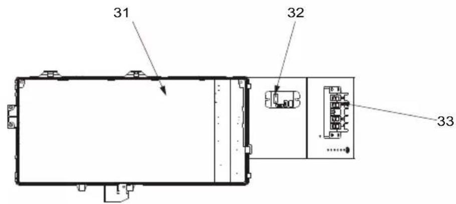
| 31 | Printed circuit board Driver | HWX72200168AP3 | ✓ | n/a | n/a n/a | |
| HWX72200168AP4 | n/a | ✓ | n/a n/a | |||
| HWX72200167AP5 | n/a n/a | ✓ | n/a | |||
| HWX72200167AP6 | n/a n/a n/a | ✓ | ||||
| 32 | K2 relay | HWX20000360297 | ✓ | ✓ | ✓ | |
| 33 | Terminal block L-N-GND 5 connections 4 mm² | HWX40003901 | ✓ | ✓ | ✓ | |
| 34 | Waterproof cover | HWX80900321 | ✓ | ✓ | ✓ |
6. APPENDIX (continued)
6.4 Troubleshooting guide

Certain operations must be carried out by an authorized technician.
If a fault occurs on the heat pump appears in the top left-hand corner of the screen.
Refer to following table.
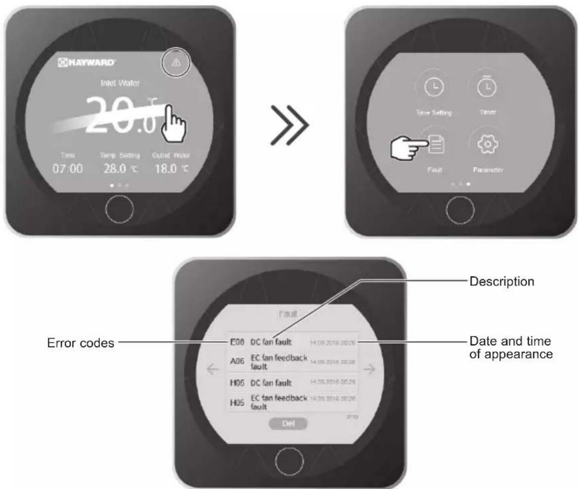

When the problem is resolved, the error is automatically acknowledged and the triangle disappears.
To delete the error list, press on
Del
Press 2 times on

return to the main screen.
6. APPENDIX (continued)
| Problem | Error codes | Description Solution | |
| Water inlet sensor fault P01 | The sensor is open or has short-circuited. | Verify the CN21/RES1 connectors on the board and the extension connector or replace the sensor | |
| Water outlet sensor fault P02 | Verify the N22/RES2 connectors on the board and the extension connector or replace the sensor | ||
| Outside temperature sensor fault P04 | Verify the CN12/PH connectors on the board and the extension connector or replace the sensor | ||
| De-icing sensor fault P05 | Verify the CN8/OPT connectors on the board and the extension connector or replace the sensor | ||
| Compressor aspiration sensor defect | P07 | Verify the CN7/OAT connectors on the board and the extension connector or replace the sensor | |
| Compressor discharge sensor fault P081 | Verify the CN9/OHT connectors on the board and the extension connector or replace the sensor | ||
| High pressure protection E01 The sensor is open or has short-circuited. | Verify the CN30/HP connectors on the card or replace the sensor | ||
| Check the water flow | |||
| Check the water flow detector | |||
| Check the valve opening | |||
| Check the by-pass | |||
| Check the evaporator is not clogged | |||
| Water temperature too hot | |||
| Incondensable problem after maintenance, empty and evacuate the cooling circuit | |||
| Fluid load too high, remove fluid into a liquid bottle | |||
| Low pressure protection E02 The sensor is open or has short-circuited. | Check the Al/DI03 connections on the card or replace the sensor | ||
| Large coolant leak, search for the leak with the detector | |||
| Air flow too low, check the ventilator rotation speed | |||
| Check the evaporator is not clogged, clean its surface | |||
| Flow sensor fault E03 The sensor is open or has short-circuited. | Check the Al/DI02 connections on the card or replace the sensor | ||
| Lack of water, check the filtration pump operation | |||
| Check the stop valve opening | |||
| Check the by-pass adjustment | |||
6. APPENDIX (continued)
| Problem | Error codes | Description Solution | |
| Input/Output temperature difference > 13°C | E06 A | Applicable in Cold mode only | Lack of water, check the filtration pump operation |
| Check the stop valve opening | |||
| Check the by-pass adjustment | |||
| Antifreeze protection Cold mode E07 | Water output temperature < 4°C | Stop the heat pump, empty the condenser risk of freezing | |
| Communication problem E08 | No communication between the printed circuit board and the user interface | Check the connectors - see the wiring diagram | |
| Level 1 antifreeze protection E19 | 2°< Water temperature < 4° and Air temperature < 0° | Stop heat pump operation, empty the condenser to avoid freezing, by default the heat pump starts the filtration pump to avoid icing over | |
| Level 2 antifreeze protection E29 | Water temperature < 2° and Air temperature < 0° | Stop heat pump operation, empty the condenser to avoid freezing, by default the heat pump starts the filtration pump and the heat pump to avoid icing over. | |
| Fan motor fault F031 Motor jammed or faulty connection | Check free rotation; check CN97/DC connectors; replace the motor | ||
| Fan motor fault F051 Faulty connection | Check the DCFAN/CN97 connector; replace the motor | ||
| Exterior temperature too low TP Operating limit reached Stop the heat pump | |||
6.5 Warranty
WARRANTY CONDITIONS
All HAYWARD products are guaranteed to be free from manufacturing or material faults for a period of two years as from the date of purchase. Any claim made under the terms of the warranty must be accompanied by a dated proof of purchase. We therefore recommend that you keep your invoice.
The HAYWARD warranty is limited to the repair or replacement, at HAYWARD's discretion, of faulty products, provided they have been used under normal conditions, as described in their user guide, and that the product has not been modified in any way and has been used only with HAYWARD components and parts. Frost and chemical damage are not covered.
No other costs (transportation, labour, etc.) are covered by the warranty.
HAYWARD cannot be held liable for any direct or indirect damage caused by the incorrect installation, connection or operation of a product.
Please contact your retailer if you want to make a claim under the terms of the warranty and request the repair or replacement of an item. No equipment returned to our factory will be accepted without our prior written agreement.
Worn parts are not covered by the warranty.
6.6 End of life of the device

The symbol of the crossed-out dustbin concerning the treatment and the reclamation of electrical and electronic waste means that the products must not be disposed of with household waste, bulky items or in a landfill under no circumstances.
At the end of life, the device must undergo selective collection so that it can be recycled or reclaimed. A specific circuit for recovering this type of products is set up in the countries of the European Union and in Norway.
Contact the installer or the local representative to have this device collected, dismantled and recycled.
Retreating the refrigerant, oil and other parts has to be carried out by a qualified accredited professional in accordance with current local and national legislation.
If the product contains batteries that bear this symbol, this means that the batteries can contain harmful or polluting substances. In this case, take the batteries to a used battery collection point.
Page left intentionally blank
UNIDAD DE BOMBA DE CALOR PARA PISCINAS
HP5091DT3HA HP5111DT3HA HP5151DT3HA HP5181DT3HA
Si el producto contiene pilas que portan este símbolo, este significa que las pilasSEOSEOSEOSEOSEOSEOSEOSEOSEOSEOSEOSEOSEOSEOSEOSEOSEOSEOSEOSEOSEOSEOSEOSEOSEOSEOSEOSEOSEOSEOSEOSEOSEOSEOSEOSEOSEOSEOSEOSEOSEOSEOSEOSEOSEOSEOSEOSEOSEOSEOSEOSEOSEOSEOSEOSEOSEOSEOSEOSEOSEOSEOSEOSEOSEOSEOSEOSEOSEOSEOSEOSEOSEOSEOSEOSEOSEOSEOSEOSEOSEOSEOSEOSEOSEOSEOSEOSEOSEOSEOSEOSEOSEOSEOSEOSEOSEOSEOSEOSEO SEOEO SEOEO SEOEO SEOEO SEOEO SEOEO SEOEO SEOEO SEOEO SEOEO SEOEO SEOEO SEOEO SEOEO SEOEO SEOEO SEOEO SEOEO SEOEO SEOEO SEOEO SEOEO SEOEO SEOEO SEOEO SEOEO SEOEO SEOEO SEOEO SEOEO SEOEO SEOEO SEOEO SEOEO SEOEO SEOEO SEOEO SEOEO SEOEO SEOEO SEOEO SEOEO SEOEO SEOEO SEOEO SEOEO SEOEO SEOEO SEOEO SEOEO SEOEQ
| Rep | Designação Ref. | HP5091DT3HA | HP5111DT3HA | HP5151DT3HA | HP5181DT3HA | |
| 1 | Painel dianteiro | HWX80900843 | ✓ | ✓ | n/a | n/a |
| HWX80900844 | n/a n/a | ✓ | n/a | |||
| HWX80900850 | n/a n/a | n/a | ✓ | |||
| 2 | Controlador LED HWX72200070 | ✓✓ | ✓✓ | |||
| 3 | Grelha de proteção do ventilador | HWX80900375 | ✓ | ✓ | ✓ | n/a |
| HWX20000220369 | n/a n/a n/a | ✓ | ||||
| 4 | Hélice ventilador | HWX301030000006 | ✓ | ✓ | n/a | n/a |
| HWX301030000001 | n/a n/a | ✓ | ✓ | |||
| 5 | / / | / | / | / | ||
| 6 | Motor do ventilador DC | HWX80200018 | ✓ | ✓ | n/a n/a | |
| HWX20000330132 | n/a n/a | ✓ | ✓ | |||
| 7 | Bobina 16 A 50 Hz 5 mH HWX82500020 | ✓ | ✓ | n/a n/a | ||
| Bobina 20 A 50 Hz 5.2 mH HWX82500021 | n/a | n/a | ✓ | ✓ | ||
| 8 | Painel esquerdo | HWX80702123 | ✓ | ✓ | n/a n/a | |
| HWX80700244 | n/a n/a | ✓ | n/a | |||
| HWX80702268 | n/a | n/a n/a | ✓ | |||
| 9 | Evaporador de alheta | HWX80600042 | ✓ | n/a n/a n/a | ||
| HWX80600043 | n/a | ✓ | n/a n/a | |||
| HWX80600044 | n/a | n/a | ✓ | n/a | ||
| HWX80600078 | n/a n/a n/a | ✓ | ||||
| 10 | Suporte do motor | HWX80700218 | ✓ | ✓ | n/a n/a | |
| HWX80700248 | n/a n/a | ✓ | n/a | |||
| HWX80700329 | n/a n/a n/a | ✓ | ||||
| 11 | / / | / / | ||||
| 12 | Painel superior | HWX80900055 | ✓ | ✓ | n/a n/a | |
| HWX301090200806 | n/a n/a | ✓ | n/a | |||
| HWX80900076 | n/a | n/a n/a | ✓ | |||
| 13 | / / / / / | |||||
| 14 | / / / / / | |||||
| 15 | Pressóstato de baixa pressão NO 0.30 MPa / 0.15 MPa | HWX20000360157 | ✓ | ✓✓ | ✓ | |
| 16 | Tomada de pressão 40 mm-1/2" | HWX20000140150 | ✓✓ | ✓✓ | ||
| 17 | Pressóstato de alta pressão NC 3.2 MPa/4.4 MPa | HWX20013605 | ✓✓ | ✓✓ | ||
| 18 | Detector de débito de água | HWX83000068 | ✓✓ | ✓✓ | ||
| 19 | Conector T Ø 6.5-2 x Ø 6.5(T) x 0.75 | HWX20001460 | ✓✓ | ✓✓ | ||
| 20 | Regulador electrónico | HWX81000011 | ✓ | ✓ | n/a n/a | |
| HWX81000013 | n/a n/a | ✓ | ✓ | |||
| 21 | Conector T Ø 9.52-2 x Ø 6.35(T) x 1.0 | HWX30403000002 | ✓ | ✓✓ | ✓ | |
| 22 | Filtro Ø 9.7-Ø 9.7 (Ø19) | HWX20000140178 | ✓ | ✓ | n/a n/a | |
| Filtro Ø 9.7-Ø 9.7 (Ø28) | HWX20041444 | n/a n/a | ✓ | ✓ | ||
| 23 | Válula de 4 vias | HWX20041437 | ✓ | ✓✓ | ✓ | |
| 24 | Alçapão de acesso eletrico HWX320922029 | ✓✓ | ✓✓ | |||
| 25 | Painel direito | HWX80700580 | ✓ | ✓ | n/a n/a | |
| HWX80700878 | n/a n/a | ✓ | n/a | |||
| HWX80700581 | n/a n/a n/a | ✓ | ||||
| 26 | Condensador Titânio/PVC | HWX72300013 | ✓ | n/a n/a n/a | ||
| HWX72300014 | n/a | ✓ | n/a n/a | |||
| HWX72300010 | n/a n/a | ✓ | n/a | |||
| HWX72300024 | n/a n/a n/a | ✓ | ||||
| 27 | / | / / / / | ||||
| 28 | Compressor | HWX80100108 | ✓ | ✓ | n/a n/a | |
| HWX80100046 | n/a n/a | ✓ | ✓ |
Apart from the problem, there are several other problems. For example, the problem of finding a solution to the following equations is not easy.
01: BUITENGAAND WATER
SUT: AANZUIGTEMPERATUURSENSOR
4V:4-WEGSKRAAN
K2: VOLTVRIJ CONTACT MAX 16 A
ET:TEMPERATUURSENSOR OPSTUWING

OPTIONEEL
| Num. | Designazione Rif. | HP5091DT3HA | HP5111DT3HA | HP5151DT3HA | HP5181DT3HA | |
| 1 | Pannello anteriore | HWX80900843 | ✓ | ✓ | n/a | n/a |
| HWX80900844 | n/a n/a | ✓ | n/a | |||
| HWX80900850 | n/a n/a | n/a | ✓ | |||
| 2 | Regulatore LED HWX72200070 | ✓✓ | ✓✓ | |||
| 3 | Griglia di protezione ventilatore | HWX80900375 | ✓ | ✓ | ✓ | n/a |
| HWX20000220369 | n/a n/a n/a | ✓ | ||||
| 4 | Elica ventilatore | HWX301030000006 | ✓ | ✓ | n/a | n/a |
| HWX301030000001 | n/a n/a | ✓ | ✓ | |||
| 5 | / / | / | / | / | ||
| 6 | Motore ventola DC | HWX80200018 | ✓ | ✓ | n/a n/a | |
| HWX20000330132 | n/a n/a | ✓ | ✓ | |||
| 7 | Bobina 16 A 50 Hz 5 mH HWX82500020 | ✓ | ✓ | n/a n/a | ||
| Bobina 20 A 50 Hz 5.2 mH HWX82500021 | n/a | n/a | ✓ | ✓ | ||
| 8 | Pannello sinistro | HWX80702123 | ✓ | ✓ | n/a n/a | |
| HWX80700244 | n/a n/a | ✓ | n/a | |||
| HWX80702268 | n/a | n/a n/a | ✓ | |||
| 9 | Evaporatore a piastre | HWX80600042 | ✓ | n/a n/a n/a | ||
| HWX80600043 | n/a | ✓ | n/a n/a | |||
| HWX80600044 | n/a | n/a | ✓ | n/a | ||
| HWX80600078 | n/a n/a n/a | ✓ | ||||
| 10 | Supporto motore | HWX80700218 | ✓ | ✓ | n/a n/a | |
| HWX80700248 | n/a n/a | ✓ | n/a | |||
| HWX80700329 | n/a n/a n/a | ✓ | ||||
| 11 | / / | / / | ||||
| 12 | Pannello superiore | HWX80900055 | ✓ | ✓ | n/a n/a | |
| HWX301090200806 | n/a n/a | ✓ | n/a | |||
| HWX80900076 | n/a | n/a n/a | ✓ | |||
| 13 | / / / / / | |||||
| 14 | / / / / / | |||||
| 15 | Pressostato Bassa pressione NO 0.30 MPa / 0.15 MPa | HWX20000360157 | ✓ | ✓✓ | ✓ | |
| 16 | Rilevamento pressione 40 mm-1/2" | HWX20000140150 | ✓✓ | ✓✓ | ||
| 17 | Pressostato Alta pressione NC 3.2 MPa/4.4 MPa | HWX20013605 | ✓✓ | ✓✓ | ||
| 18 | Rilevatore portata acqua | HWX83000068 | ✓✓ | ✓✓ | ||
| 19 | Connettore a T Ø 6.5-2 x Ø 6.5(T) x 0.75 | HWX20001460 | ✓✓ | ✓✓ | ||
| 20 | Riduttore di pressione elettronico | HWX81000011 | ✓ | ✓ | n/a n/a | |
| HWX81000013 | n/a n/a | ✓ | ✓ | |||
| 21 | Connettore a T Ø 9.52-2 x Ø 6.35(T) x 1.0 | HWX30403000002 | ✓ | ✓✓ | ✓ | |
| 22 | Filtro Ø 9.7-Ø 9.7 (Ø19) | HWX20000140178 | ✓ | ✓ | n/a n/a | |
| Filtro Ø 9.7-Ø 9.7 (Ø28) | HWX20041444 | n/a n/a | ✓ | ✓ | ||
| 23 | Valvola 4 vie | HWX20041437 | ✓ | ✓✓ | ✓ | |
| 24 | Portello d'acceso scatola elettrica | HWX320922029 | ✓✓ | ✓✓ | ||
| 25 | Pannello destro | HWX80700580 | ✓ | ✓ | n/a n/a | |
| HWX80700878 | n/a n/a | ✓ | n/a | |||
| HWX80700581 | n/a n/a n/a | ✓ | ||||
| 26 | Condensatore Titanio/PVC | HWX72300013 | ✓ | n/a n/a n/a | ||
| HWX72300014 | n/a | ✓ | n/a n/a | |||
| HWX72300010 | n/a n/a | ✓ | n/a | |||
| HWX72300024 | n/a n/a n/a | ✓ | ||||
| 27 | / | / / / / | ||||
| 28 | Compressore | HWX80100108 | ✓ | ✓ | n/a n/a | |
| HWX80100046 | n/a n/a | ✓ | ✓ |
6. APPENDICI (segue)
HP5091DT3HA / HP5111DT3HA / HP5151DT3HA / HP5181DT3HA

6. APPENDICI (segue)
| Num. | Designazione Rif. | HP5091DT3HA | HP5111DT3HA | HP5151DT3HA | HP5181DT3HA | |
| 29 | Sonda di aspirazione compressore 5 k - 560 mm | HWX83000044 | ✓ | ✓ | n/a n/a | |
| Sonda di aspirazione compressore 5 k - 760 mm | HWX83000053 n/a | n/a | ✓ | ✓ | ||
| Sonda temperatura aria Air 5 k - 350 mm | HWX83000049 | ✓✓ | ✓✓ | |||
| Sonda uscita acqua 5 k - 410 mm HWX83000050 | 000050 | ✓✓ | ✓✓ | |||
| Sonda temperatura acqua in ingresso 5 k - 850 mm | HWX83000052 | ✓✓ | ✓ | n/a | ||
| Sonda temperatura acqua in ingresso 5 k - 980 mm | HWX83000055 n/a | n/a n/a | ✓ | |||
| Sonda scarico compressore 50 k - 660 mm | HWX83000026 | ✓✓ | ✓✓ | |||
| Sonda antigelo 5 k - 680 mm HWX83000051 | 51 | ✓ | ✓ | n/a n/a | ||
| Sonda antigelo 5 k - 1040 mm HWX83000045 | 045 | ✓✓ | ✓✓ | |||
| 30 | Filtro EMC | HWX20003257 | n/a n/a | ✓ | ✓ | |
| 31 | Scheda elettronica Driver | HWX72200168AP3 | ✓ | n/a n/a n/a | ||
| HWX72200168AP4 | n/a | ✓ | n/a n/a | |||
| HWX72200167AP5 | n/a n/a | ✓ | n/a | |||
| HWX72200167AP6 | n/a | n/a n/a | ✓ | |||
| 32 | Relè K2 HWX20000360297 | ✓✓ | ✓✓ | |||
| 33 | Morsettiera L-N-GND 5 connessioni 4 mm² | HWX40003901 | ✓✓ | ✓✓ | ||
| 34 | Porta di protezione | HWX80900321 | ✓ | ✓✓ | ✓ |
6. APPENDICI (segue)
1. GENERELLE FORHOLDSGREGLER (fortsetter)
Dette Produktetinneholderkjølegassen R32

Dette apparatet inneholder R32.
(1) Globalt oppvarmingspotensial
1. GENERELLE FORHOLDSREGLER (fortsetter)
Betingelser for installing
1. GENERELLE FORHOLDSGREGLER (fortsetter)
2. SPESIFIKASJONER (fortsetter)
2.2 Driftsområde
Bruk varmepumpen i de følgende temperatur- og faktighetsområder for Å sikre en trygg og effektiv drift.
| Oppvarmingsmodus Kjatemoos | ||
| Utetemperatur -7°C – +35°C +7°C – +43°C | ||
| Vanntemperatur +12°C – +32°C +8°C – +40°C | ||
| Relativ luftfuktigkeit < 80% < 80% | ||
| Innstillingsområde for settpunkt +15°C – +32°C +8°C – +32°C |

Hvis temperatur aller luftfuktigkeit不解 samsvarer med disse betingelsene, kan sikkerhetsanordninger aktiveres og varmepumpen slutte ä fungere.

2. SPESIFIKASJONER (fortsetter)
2.3 Dimensjoner
Modeller:
HP5091DT3HA / HP5111DT3HA / HP5151DT3HA / HP5181DT3HA

Enhet: mm
| Model Nummer | HP5091DT3HA / HP5111DT3HA | HP5151DT3HA HP | 5181DT3HA |
| A 418 436 | 5 473 | ||
| B 374 418 | 451,5 | ||
| C 604,5 767,5 862 | |||
| D 1003 1047,5 1160,5 | |||
| E 956 1002 | 1115 | ||
| F | 535 615 | 790 | |
| G | 394,5 410 | 447 | |
| H 350 350 | 466 | ||
| I | 97,7 | 101,2 | 97,6 |
| J | 99,2 | 106,5 | 113,5 |
3. INSTALLERING OG TILKOBLING
3.1 Skjematisk diagram
3. INSTALLERING OG TILKOBLING (fortsetter)

3. INSTALLERING OG TILKOBLING (fortsetter)
3.3 Vanntilkobling
Varmepumpen leveres med to koblingsdeler med diameter på 50 mm. Bruk PVC-rør på Ø 50 mm for vannkanaler. Koble varmepumpens vanninnlp til kanalen fra filteringsenheten, og koble deretter varmepumpens vannutlp til kanalen som går til bassenget (se diagram nedenfor).
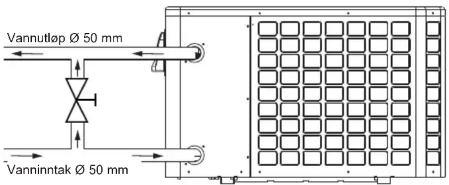
Installer en bypassventil mellom varmepumpens vanninnlp og vannutlp.

Dersom automatisk fordeler eller klordoseringscelle benyttes,帽子det��reinstallertettervarmepumpen,fora beskytte Titanium-kondensatorenmot en forstor konsentrasjon av kjemiske stoffer.

3. INSTALLERING OG TILKOBLING (fortsetter)
3.4 Elektrisk tilkobling

3. INSTALLERING OG TILKOBLING (fortsetter)

3. INSTALLERING OG TILKOBLING (fortsetter)
3. INSTALLERING OG TILKOBLING (fortsetter)
4. BRUKERGRENSNITT (fortsetter)
OFF-modus
När varmepumpen er stanset (i standby), vil teksten OFF vises paskjermen.
4. BRUKERGRENSNITT (fortsetter)
4. BRUKERGRENSNITT (fortsetter)
4. BRUKERGRENSNITT (fortsetter)


Blå marking = Aktivert
Nedtonet = Deaktivert
4. BRUKERGRENSNITT (fortsetter)
4. BRUKERGRENSNITT (fortsetter)
4.5 Låse og进展情况 opp berøringsskjermen
4. BRUKERGRENSNITT (fortsetter)
4. BRUKERGRENSNITT (fortsetter)
4. BRUKERGRENSNITT (fortsetter)
6. VEDLEGG (fortsetter)
HP5151DT3HA / HP5181DT3HA
MERKNADER
AT:SENSOR FOR LUFTTEMPERATUR
COMP: KOMPRESSOR
CT: SENSOR FOR FORDAMPET TEMPERATUR
EEV: ELEKTRONISK EKSPANSJONSVENTIL
FM:VIFTEMOTOR
FS: VANNSENSOR
HP:HOTYTRYKKSBRYTER
IT: TEMPERATURSENSOR TIL VANNINNLØP
LP:LAVTRYKKSBRYTER
OT:TEMPERATURSENSOR TIL VANNUTLØP
SUT: SENSOR FOR SUGETEMPERATUR
4V:4-VEIS VENTIL
K2: POTENSIALFRI KONTAKT, MAKS. 16 A
ET:TEMPERATURSENSOR FOR UTLADNING
OPSJON
6. VEDLEGG (fortsetter)
6.2 Kobling med prioritet på enfaset varmepumpe
"Terminalene 1 og 2 gir et tört kontaktpotensial uten polaritet 230V_ / 50Hz
6. VEDLEGG (fortsetter)
6.3 Sprengskisse og resedeler
HP5091DT3HA / HP5111DT3HA / HP5151DT3HA / HP5181DT3HA

6. VEDLEGG (fortsetter)
| Nr. | Betegnelse Réf. | HP5091DT3HA | HP5111DT3HA | HP5151DT3HA | HP5181DT3HA | |
| 1 | Fremre panel | HWX80900843 | ✓ | ✓ | Gjelder ilke | Gjelder ilke |
| HWX80900844 | Gjelder ilke Gjelder ilke | ✓ | Gjelder ilke | |||
| HWX80900850 | Gjelder ilke Gjelder ilke | Gjelder ilke | ✓ | |||
| 2 | Controller LED HWX72200070 | ✓✓ | ✓✓ | |||
| 3 | Beskyttesgitter for viften | HWX80900375 | ✓ | ✓ | ✓ | Gjelder ilke |
| HWX20000220369 | Gjelder ilke Gjelder ilke Gjelder ilke | ✓ | ✓ | ✓ | ||
| 4 | Vifteproprell | HWX301030000006 | ✓ | ✓ | Gjelder ilke | Gjelder ilke |
| HWX301030000001 | Gjelder ilke Gjelder ilke | ✓ | ✓ | ✓ | ||
| 5 | /// | / | / | / | ||
| 6 | Viftemotor DC | HWX80200018 | ✓ | ✓ | Gjelder ilke Gjelder ilke | Gjelder ilke |
| HWX20000330132 | Gjelder ilke Gjelder ilke | ✓ | ✓ | ✓ | ||
| 7 | Spole 16 A 50 Hz 5 mH HWX82500020 | ✓ | ✓ | Gjelder ilke Gjelder ilke | Gjelder ilke | |
| Spole 20 A 50 Hz 5.2 mH HWX82500021 | Gjelder ilke | Gjelder ilke | ✓ | ✓ | ||
| 8 | Venstre panel | HWX80702123 | ✓ | ✓ | Gjelder ilke Gjelder ilke | Gjelder ilke |
| HWX80700244 | Gjelder ilke Gjelder ilke | ✓ | ✓ | Gjelder ilke | ||
| HWX80702268 | Gjelder ilke | Gjelder ilke Gjelder ilke | ✓ | ✓ | ||
| 9 | Vinget fordamper | HWX80600042 | ✓ | Gjelder ilke Gjelder ilke Gjelder ilke | Gjelder ilke Gjelder ilke | Gjelder ilke |
| HWX80600043 | Gjelder ilke | ✓ | Gjelder ilke Gjelder ilke | Gjelder ilke | ||
| HWX80600044 | Gjelder ilke | ✓ | ✓ | Gjelder ilke | ||
| HWX80600078 | Gjelder ilke Gjelder ilke Gjelder ilke | ✓ | ✓ | ✓ | ||
| 10 | Motorstøtte | HWX80700218 | ✓ | ✓ | Gjelder ilke Gjelder ilke | Gjelder ilke |
| HWX80700248 | Gjelder ilke Gjelder ilke | ✓ | ✓ | Gjelder ilke | ||
| HWX80700329 | Gjelder ilke Gjelder ilke Gjelder ilke | ✓ | ✓ | ✓ | ||
| 11 | /// | /// | ||||
| 12 | Øvre panel | HWX80900055 | ✓ | ✓ | Gjelder ilke Gjelder ilke | Gjelder ilke |
| HWX301090200806 | Gjelder ilke Gjelder ilke | ✓ | ✓ | Gjelder ilke | ||
| HWX80900076 | Gjelder ilke | Gjelder ilke Gjelder ilke | ✓ | ✓ | ||
| 13 | /// /// | |||||
| 14 | /// /// | |||||
| 15 | Stromningsbegrenser NO 0.30 MPa / 0.15 MPa | HWX20000360157 | ✓ | ✓✓ | ✓ | |
| 16 | Trykktilkobling 40 mm-1/2" | HWX20000140150 | ✓✓ | ✓✓ | ✓ | |
| 17 | Høytrykkspressostat NC 3.2 MPa/4.4 MPa | HWX20013605 | ✓✓ | ✓✓ | ✓ | |
| 18 | Sensor for vannstrømning | HWX83000068 | ✓✓ | ✓✓ | ✓ | |
| 19 | T-formet connector Ø 6.5-2 x Ø 6.5(T) x 0.75 | HWX20001460 | ✓✓ | ✓✓ | ✓ | |
| 20 | Elektronisk ekspansjonsventil | HWX81000011 | ✓ | ✓ | Gjelder ilke Gjelder ilke | Gjelder ilke |
| HWX81000013 | Gjelder ilke Gjelder ilke | ✓ | ✓ | ✓ | ||
| 21 | T-formet connector Ø 9.52-2 x Ø 6.35(T) x 1.0 | HWX30403000002 | ✓✓ | ✓✓ | ✓ | |
| 22 | Filter Ø 9.7-Ø 9.7 (Ø19) | HWX20000140178 | ✓ | ✓ | Gjelder ilke Gjelder ilke | Gjelder ilke |
| Filter Ø 9.7-Ø 9.7 (Ø28) | HWX20041444 | Gjelder ilke Gjelder ilke | ✓ | ✓ | ✓ | |
| 23 | 4-veisventil | HWX20041437 | ✓✓ | ✓✓ | ✓ | |
| 24 | Trappe elektrisk tilgang | HWX320922029 | ✓✓ | ✓✓ | ✓ | |
| 25 | Høyre panel | HWX80700580 | ✓ | ✓ | Gjelder ilke Gjelder ilke | Gjelder ilke |
| HWX80700878 | Gjelder ilke Gjelder ilke | ✓ | ✓ | Gjelder ilke | ||
| HWX80700581 | Gjelder ilke Gjelder ilke Gjelder ilke Gjelder ilke | ✓ | ✓ | ✓ | ||
| 26 | Kondensator Titanium/PVC | HWX72300013 | ✓ | Gjelder ilke Gjelder ilke Gjelder ilke | Gjelder ilke Gjelder ilke | Gjelder ilke |
| HWX72300014 | Gjelder ilke | ✓ | Gjelder ilke Gjelder ilke | Gjelder ilke | ||
| HWX72300010 | Gjelder ilke Gjelder ilke | ✓ | ✓ | Gjelder ilke | ||
| HWX72300024 | Gjelder ilke Gjelder ilke Gjelder ilke | ✓ | ✓ | ✓ | ||
| 27 | /// /// | |||||
| 28 | Kompressor | HWX80100108 | ✓ | ✓ | Gjelder ilke Gjelder ilke | Gjelder ilke |
| HWX80100046 | Gjelder ilke Gjelder ilke | ✓ | ✓ | ✓ |
6. VEDLEGG (fortsetter)
HP5091DT3HA / HP5111DT3HA / HP5151DT3HA / HP5181DT3HA


6. VEDLEGG (fortsetter)
| Nr. Betegnelse Réf. | HP5091DT3HA | HP5111DT3HA | HP5151DT3HA | HP5181DT3HA | |
| Kompressorsugesonde5 k - 560 mm | HWX83000044 | ✓ | ✓ | Gjelder ikke Gjelder ikke | |
| Kompressorsugesonde5 k - 760 mm | HWX83000053 | Gjelder ikke Gjelder ikke | ✓ | ||
| Lufttemperatur probe 5 k - 350 mm HWX83000049 | ✓ | ✓ | ✓ | ||
| Vannuttak probe 5 k - 410 mm HWX83000050 | ✓ | ✓ | ✓ | ||
| Vanninntak probe 5 k - 850 mm HWX83000052 | ✓ | ✓ | Gjelder ikke | ||
| Vanninntak probe 5 k - 980 mm HWX83000055 | Gjelder ikke Gjelder罘ngåse | ||||
| Kompressorutladningssonde50 k - 660 mm | HWX83000026 | ✓ | ✓ | ✓ | |
| Avrimings sensor 5 k - 680 mm HWX83000051 | ✓ | ✓ | Gjelderøyte Gjelderøyte | ||
| Avrimings sensor 5 k - 1040 mm HWX83000045 | ✓ | ✓ | |||
| 30 EMC Filter | HWX20003257 | Gjelderøyte Gjelderøyte | ✓ | ✓ | |
| HWX72200168AP3 | ✓ | Gjelderøyte | Gjelderøyte Gjelderøyte | ||
| 31 Elektronisk Driver-kort | HWX72200168AP4 | Gjelderøyte | ✓ | Gjelderøyte Gjelderøyte | |
| HWX72200167AP5 | Gjelderøyte Gjelderøyte | ✓ | Gjelderøyte | ||
| HWX72200167AP6 | Gjelderøyte Gjelderøyte Gjelderøyte | ||||
| 32 Relé K2 | HWX20000360297 | ✓ | ✓ | ✓ | |
| 33 Terminal L-N-GND - 5 tilkoplinger 4 mm2 | HWX40003901 | ✓ | ✓ | ✓ | |
| 34 Beskyttelsesdør | HWX80900321 | ✓ | ✓ | ✓ | |
6. VEDLEGG (fortsetter)
Se tabellen longer ned.


6. VEDLEGG (fortsetter)
6. VEDLEGG (fortsetter)
2. TEXHnueCKNE XAPAKTEPNUCTUKN 5
2.1 Texnueckne daHbIe TeIIOBOrO Hacoca 5
2.2 Pa6oyn dnaana30H 6
2.3 Pa3Mepbl 7
3. YCTAHOBKA I NOdkJIIOUYEHNE 8
3.1ПинциальнаСхema8
3.2 TepnoBoH hacoc 8
3.3 TnIpoTeXHnueckoe nOdkJIouyeHne 10
3.4 Θлжгпческoe ПОдклочене 11
3.5Первьн залус 12
3.6 YcTaHOBka npOnyckHo cnocObHOCTn Hacoca 14
5. TEXHnueCKOE OBCJIyXnBAHnE - 3IMOBKA
5.1 TexHnueckoe obcIyJxNBaHne
Дя rapаHTIPOBAHЯ npOJXnTeJbHOи HaJeXHO pa6OtBI TeIIOBOrO Hacoca peKOMeHNdyETcra3В rOd npOBODITb cIeDyUoIne Oepaunn no 06CnyKINBaHNU yCTpOInCTBa.
- 06cIyKbAHHe n peMOHT yCTPOHCTBa DOJXHbI BblIOJIHrTbcK KBaIINΦnIupOBaHHbIM CneUaJIHCTOM B COOTBeTCTBUN C HOpMaTHNBbIMN DOKyMeHTaMn I OTPaCJIeBbIMN CTaHdApTaMn, DeIcTBYIOUImN B CTpaHE, B KOTOpO YCTPOHCTBO 6yJeT yCTaHaBNIbA TbCBsC (CM. § 3.4). JIO6bIe pa6oTbIC XOJODINbHbIM KOHTypOM DOJXKeH BblIOJIHrTb CneUaJIHCT, IMeJOUIn cepTnΦNKaT, NOITBepJdaIOUm npaBO pa6oTbIC xJaIaReHTaMn.
- Пюверьтшнур питуня.Есишнур питуня NOBpeждн,ERO cnedehyet 3amehntb y npoIN3BOIDNTeIy, B cnyk6e nocJIepnoDAxHOrO O6cnykBaHnY IIn y IIO60rO Jnua, IMeIoUeRO COOTBeTCTByIOu KBaJIINФИKaUHIO.
- Поберп Teць 3a3eMJIeHnY yCTpoIcTbA n ee HeIpepbIBHOCTb.
OuHCTIe nCnapnteB C NOMOUsbMOyKoN 3y6HOJ UeTKN IIN BO3dyUH0/ BOJHOcTpyn. BHMaHHe: HkOrda He nCpOJb3yUTe dJa OChCTKn BBICOKOE DaBJIeHne. - Поберът,чTo KOндсатхopoшостkaeT.
- Поберъпаджноь ГдрOTEXHnuecknx И олктpruecknx coeINHeHn.
- Поверътгдравли ueckую repmetnuehoctь KOнdeHcaTopa.
- Пюверку Изоляцихолдьн системы Вьлоггет улномоевский спесиаист сnomошю DeTeKTopa Teу.

Ipepe npou3bodcmeom nio6bix pa6om no mexHuyeckomy 06cnykuaHIO mennoo2o hacoca heo6xodmo omcoedunmb eO om ucmouhka numanur. Bce onepauu no mexHuyeckomy 06cnykuaHIO doJXHBI npou3bodumbcra molbko cneuaJIbHO nOdozmoeHHbIM nepcoHaIOM, UMeIoUUM onbim pa6omblc kudKumu xnaadaeHmamu.
5. TEXHnueCKOE OBCJyKINBAHNE (npoJxKeHne)
m = 311
CnmboI nepeepKhyToi KOp3HbI, 603HaauOuN i nepepa6tky uyttnaun oJNeKtpnuecknx H 3neKtpoHHbIX OTXODOB, O3HaayET, UTO n3dennr, OTMeueHHbIe TaKIM CnMBONOM, HeNb3R Bbl6pacbIBaTb BMeCTe C 6bITOBbIM MycOpOM, KpynHora6apNTbIM NpeDMTaMn IIN Ha CBanky.
No OKOHuaHn cPoka cnjx6bl yCTpoiCTBO Heo6xoJIMO OTdaTb OTdJIbHO
Hayward® is registered trademark
of Hayward Holdings, Inc.
© 2023 Hayward Holdings, Inc.
CE
m = 311 ;