
SumHeat Fi - Pump HAYWARD - Free user manual and instructions
Find the device manual for free SumHeat Fi HAYWARD in PDF.

| Brand | Hayward |
| Model | SumHeat Fi (series HP5171DT3 to HP5301ET3) |
| Product type | Heat pump for swimming pool |
| Dimensions (L x W x H) | From 780 x 730 x 868 mm to 846 x 920 x 1024 mm depending on model |
| Weight | From 75 to 123 kg depending on model |
| Power supply | Single-phase 230 V ~ 50 Hz or three-phase 400 V 3N ~ 50 Hz depending on model |
| Refrigerant | R32 (HFC), Safety group A2L, GWP 675 |
| Heating capacity (min-max) | From 2.87 kW to 31.20 kW depending on model and conditions |
| COP (min-max) | From 4.79 to 15.00 depending on model and conditions |
| Water temperature range | Heating: +12 °C to +40 °C; Cooling: +8 °C to +40 °C |
| Outdoor temperature range | Heating: -15 °C to +43 °C; Cooling: +7 °C to +43 °C |
| Sound level (at 1 m) | From 49.3 to 62.5 dB(A) depending on model and speed |
| Hydraulic connection | 50 mm (2 x union connectors supplied) |
| Nominal water flow | From 7.2 to 13.1 m³/h depending on model |
| Main functions | Heat/cool mode, Full Inverter regulation, silent mode, programmable timer, touch screen, automatic lock |
| Annual maintenance | Evaporator cleaning (soft brush or water jet), check cables, connections and sealing, by a certified professional |
| Winterizing | Power off, drain condenser, seal inlet/outlet, cover with winter cover |
| Electrical protection | Type D circuit breaker + 30 mA residual current device mandatory |
| Spare parts | Available from dealer; exploded views in the manual (section 6.4) |
| Warranty | 2 years against manufacturing defects (excluding wear parts and frost damage) |
| Standards | CE compliant, NF C15-100 (France), R32 according to F-Gas regulation |
Frequently Asked Questions - SumHeat Fi HAYWARD
User questions about SumHeat Fi HAYWARD
0 question about this device. Answer the ones you know or ask your own.
Ask a new question about this device
Download the instructions for your Pump in PDF format for free! Find your manual SumHeat Fi - HAYWARD and take your electronic device back in hand. On this page are published all the documents necessary for the use of your device. SumHeat Fi by HAYWARD.
USER MANUAL SumHeat Fi HAYWARD
natural_image
Exterior view of a modern industrial water filter unit (no visible text or symbols)
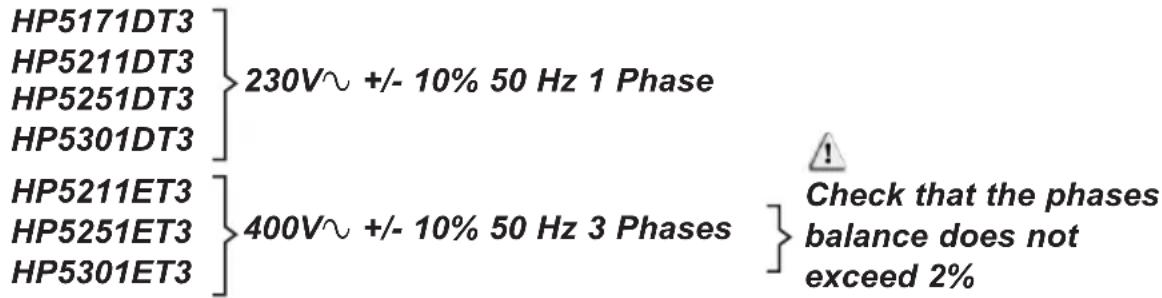
HP5171DT3 HP5211DT3 HP5251DT3 HP5301DT3 HP5211ET3 HP5251ET3 HP5301ET3
natural_image
Exterior view of a modern industrial water heater (no visible text or symbols)
HP5171DT3 HP5211DT3 HP5251DT3 HP5301DT3 HP5211ET3 HP5251ET3 HP5301ET3
3.3 Raccordement hydraulique
Alimentation générale 400V 3N\~ / 50Hz
4. INTERFACE UTILISATEUR (suite)
Réglage du Timer

4. INTERFACE UTILISATEUR (suite)
LEGENDE
natural_image
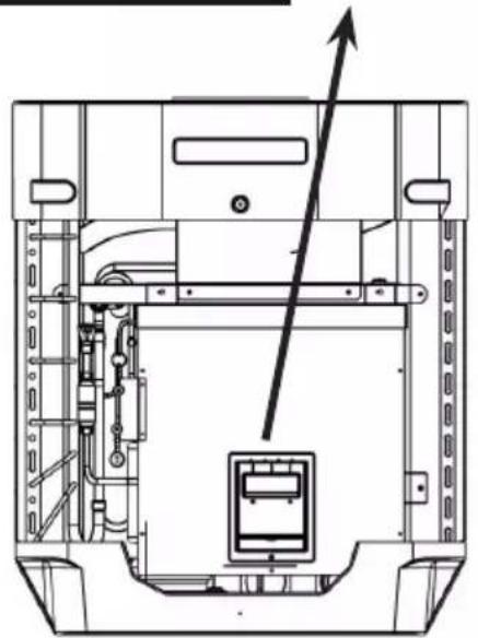
Technical line drawing of a mechanical device with internal components and an upward arrow indicator (no text or symbols)6. ANNEXES (suite)
6.3 Raccordements priorité chauffage Pompe Triphasé

natural_image
Technical line drawing of a mechanical device with internal components and an upward arrow indicator (no text or symbols)6. ANNEXES (suite)

HP5171DT3 / HP5211DT3 / HP5251DT3 / HP5301DT3
| Rep | Désignation P/N | HP5171DT3 | HP5211DT3 | HP5251DT3 | HP5301DT3 | |
| 1 | Moteur ventilateur DC | HWX20000330381 | √ | √ | √ | |
| HWX20000330402 n/a | n/a | n/a | ||||
| 2 | Capot protection moteur HWX20000220320 | √ | √ | √ | ||
| 3 | Panneau supérieur ABS | HWX80900736 | √ | n/a | n/a | |
| HWX80900737 n/a | √ | √ | ||||
| HWX80900718 n/a | n/a | n/a | ||||
| 4 | Protection latérale droite | HWX80704158 | √ | n/a | n/a | |
| HWX80705113 n/a | √ | √ | ||||
| HWX80705110 n/a | n/a | n/a | ||||
| 5 | / / / / / / | |||||
| 6 | Plaque de protection | HWX32012210724 | √ | n/a | n/a | |
| HWX32002210071 n/a | √ | √ | ||||
| HWX32004210137 n/a | n/a | n/a | ||||
| 7 | Prise de pression 90 mm - 1/2" | HWX20000140153 | √ | √ | √ | |
| 8 | Détendeur électronique | HWX20000140451 | √ | n/a | n/a | |
| HWX20000140449 n/a | √ | n/a | ||||
| HWX20000140442 n/a | n/a | √ | ||||
| HWX20000140401 n/a | n/a | n/a | ||||
| 9 | Filtre ∅12.9-∅12.9 (∅28) | HWX20000140027 | √ | √ | √ | |
| 10 | Prise de pression 95 mm - 7/16" | HWX20000140512 | √ | √ | √ | |
| 11 | Prise de pression 40 mm - 1/2" | HWX20000140150 | √ | √ | √ | |
| 12 | Vanne 4 voies | HWX20041437 | √ | n/a | n/a | |
| HWX20011491 n/a | √ | √ | ||||
| 13 | Capteur de pression | HWX20000360274 | √ | √ | √ | |
| 14 | Sonde température Évap/Air/Eau 5k-800 mm HWX20003202 | √ | √ | √ | ||
| 15 | Sonde Refoulement Compresseur 50k-600 mm | HWX20000320145 | √ | √ | √ | |
| 16 | Détecteur de débit d'eau | HWX83000069 | √ | √ | √ | |
| 17 | / / / / / / | |||||
| 18 | Panneau Avant | HWX80900738 | √ | n/a | n/a | |
| HWX80900739 n/a | √ | √ | ||||
| HWX80900710 n/a | n/a | n/a | ||||
| 19 | Écran tactile couleur | HWX95005310612 | √ | √ | √ | |
| 20 | Trappe d'accès électrique | HWX20000220247 | √ | √ | √ | |
| 21 | Panneau boîtier électrique | HWX80702647 | √ | n/a | n/a | |
| HWX80702644 n/a | √ | √ | ||||
| HWX80702645 n/a | n/a | n/a | x | |||
| 22 | Pressostat haute pression NC 3.2MPa/4.4 MPa | HWX20000360187 | √ | √ | √ | |
| 23 | Pressostat basse pression NO 0.15 MPa/0.05 MPa | HWX20000360054 | √ | √ | √ | |
| 24 | / / / / / / | |||||
| 25 | Condenseur Titane PVC | HWX32009120085 | √ | n/a | n/a | |
| HWX32002120023 n/a | √ | n/a | ||||
| HWX32016120012 n/a | n/a | √ | ||||
| HWX32016120011 | n/a | n/a | ||||
| 26 | / / / / / / | |||||
| 27 | Compresseur | HWX80100046 | √ | n/a | n/a | |
| HWX80100069 n/a | √ | √ | ||||
| HWX30101000006 n/a | n/a | n/a | ||||
| 28 | Protection latérale gauche | HWX32012210729 | √ | n/a | n/a | |
| HWX80705114 n/a | √ | √ | ||||
| HWX80705111 | n/a | n/a |
6. ANNEXES (suite)
HP5171DT3 / HP5211DT3 / HP5251DT3 / HP5301DT3
HP5171DT3 / HP5211DT3 / HP5251DT3 / HP5301DT3
| Rep | Désignation P/N | HP5171DT3 | HP5211DT3 | HP5251DT3 | HP5301DT3 | |
| 29 | / / / / / | |||||
| 30 | Connecteur carré fileté 50 mm HWX20031379 | √ | √ | √ | ||
| 31 | Coude PVC ∅ 50 mm HWX20011359 | √ | √ | √ | ||
| 32 | Support vertical droit/gauche | HWX32000210086 | √ | n/a n/a n/a | ||
| HWX80702346 n/a | √ | √ | n/a | |||
| HWX80702656 n/a | n/a n/a | √ | ||||
| 33 | Evaporateur à ailette | HWX32012120155 | √ | n/a n/a n/a | ||
| HWX80600429 n/a | √ | n/a n/a | ||||
| HWX32003120028 | n/a n/a | √ | n/a | |||
| HWX32004120013 | n/a n/a n/a | √ | ||||
| 34 | Protection arrière | HWX32012210730 | √ | n/a n/a n/a | ||
| HWX80705115 | n/a | √ | √ | n/a | ||
| HWX80705112 | n/a n/a n/a | √ | ||||
| 35 | / / / / / | |||||
| 36 | Hélice Ventilateur ∅ 522 mm | HWX20000270062 | √ | n/a n/a n/a | ||
| Hélice Ventilateur ∅ 560 mm | HWX35072195 n/a | √ | √ | n/a | ||
| Hélice Ventilateur ∅ 600 mm | HWX20000270057 | n/a | n/a | n/a | √ | |
| 37 | Grille de protection ventilateur | HWX32012210732 | √ | n/a n/a n/a | ||
| HWX32003210142 | n/a | √ | √ | n/a | ||
| HWX80700160 n/a | n/a n/a | √ | ||||
| 38 | Carte électronique Mère | HWX72200033171D | √ | n/a n/a n/a | ||
| HWX72200033211D | n/a | √ | n/a n/a | |||
| HWX72200033251D | n/a n/a | √ | n/a | |||
| HWX72200033301D | n/a n/a n/a | √ | ||||
| 39 | Carte Inverter ventilateur | HWX82300485 | √ | √ | √ | |
| 40 | Bornier 4 connexions | HWX20003909 | √ | √ | √ | |
| 41 | Carte filtre | HWX3020100007 | √ | √ | √ | |
| 42 | Relais K2 | HWX20000360297 | √ | √ | √ | |
| 43 | Bornier L-N-GND | HWX20000390223 | √ | √ | √ | |
| 44 | Bornier 4 pôles | HWX20000390046 | √ | √ | √ | |
| 45 | Bobine réactance | HWX82500009 | √ | n/a n/a n/a | ||
| HWX20000370030 | n/a | √ | √ | √ | ||
| 46 | / / / / / | |||||
| 47 | / / / / / | |||||
| 48 | Carte Inverter compresseur | HWX82300149 | √ | n/a n/a n/a | ||
| HWX82300019 n/a | √ | √ | √ | |||
| 49 | Résistance PTC 100 Ω | HWX20000320113 | n/a | √ | √ | √ |
| 50 | / / / / / | |||||
| 51 | / / / / / | |||||
| 52 | Contacteur de puissance | HWX200003600619 | n/a | √ | √ | √ |
| 53 | Bouteille de liquide | HWX20000140579 | n/a | n/a | √ | √ |
6. ANNEXES (suite)
HP5211ET3 / HP5251ET3 / HP5301ET3


HP5211ET3 / HP5251ET3 / HP5301ET3
| Rep | Désignation P/N HP5211ET3 HP5251ET3 HP530 | 1ET3 | |||
| 1 M | Moteur ventilateur DC | HWX20000330381 | √ | √ | n/a |
| HWX20000330402 n/a | n/a | √ | |||
| 2 Capot protection moteur HWX20000220320 | √ √ | √ | |||
| 3 Panneau supérieur | HWX80900737 | √ | √ | n/a | |
| HWX80900718 n/a | n/a | √ | |||
| 4 Protection latérale droite | HWX80705113 | √ | √ | n/a | |
| HWX80705110 n/a | n/a | √ | |||
| 5 / / | / / | ||||
| 6 Plaque de protection | HWX32002210071 | √ | √ | n/a | |
| HWX32004210137 n/a | n/a | √ | |||
| 7 Prise de pression 90 mm - 1/2" | HWX20000140153 | √ √ | √ | ||
| 8 Détendeur électronique | HWX20000140449 | √ | n/a | n/a | |
| HWX20000140442 n/a | √ | n/a | |||
| HWX20000140401 n/a | n/a | √ | |||
| 9 Filtre ∅12.9-∅12.9 (∅28) | HWX20000140027 | √ √ | √ | ||
| 10 | Prise de pression 95 mm - 7/16" | HWX20000140512 | √ √ | √ | |
| 11 | Prise de pression 40 mm - 1/2" | HWX20000140150 | √ √ | √ | |
| 12 | Vanne 4 voies | HWX20011491 | √ √ | √ | |
| 13 | Capteur de pression | HWX20000360274 | √ √ | √ | |
| 14 | Sonde température Évap/Air/Eau 5k-800 mm | HWX20003202 | √ √ | √ | |
| 15 | Sonde Refoulement Compresseur 50k-600 mm | HWX20000320145 | √ √ | √ | |
| 16 | Détecteur de débit d'eau | HWX83000069 | √ √ | √ | |
| 17 | /// / / | ||||
| 18 | Panneau Avant | HWX80900739 | √ | √ | n/a |
| HWX80900710 n/a | n/a | √ | |||
| 19 | Écran tactile couleur | HWX95005310612 | √ √ | √ | |
| 20 | Trappe d'accès électrique | HWX20000220247 | √ √ | √ | |
| 21 | Panneau boîtier électrique | HWX80702644 | √ | √ | n/a |
| HWX80702645 n/a | n/a | √ | |||
| 22 | Pressostat haute pression NC 3.2 MPa/4.4 MPa | HWX20000360187 | √ √ | √ | |
| 23 | Pressostat basse pression NO 0.15 MPa/0.05 MPa | HWX20000360054 | √ √ | √ | |
| 24 | /// / / | ||||
| 25 | Condenseur Titane PVC | HWX32002120023 | √ | n/a | n/a |
| HWX32016120012 n/a | √ | n/a | |||
| HWX32016120011 | n/a | n/a | √ | ||
| 26 | /// / / | ||||
| 27 | Compresseur | HWX80100069 | √ | √ | n/a |
| HWX30101000006 n/a | n/a | √ | |||
| 28 | Protection latérale gauche | HWX80705114 | √ | √ | n/a |
| HWX80705111 | n/a | n/a | √ | ||
| 29 | /// / / | ||||
| 30 | Connecteur carré fileté 50 mm | HWX20031379 | √ √ | √ | |
| 31 | Coude PVC ∅ 50 mm | HWX20011359 | √ √ | √ | |
| 32 | Support vertical droit/gauche | HWX80702346 | √ | √ | n/a |
| HWX80702656 n/a | n/a | ||||
| 33 | Évaporateur à ailette | HWX80600429 | √ | n/a | n/a |
| HWX32003120028 n/a | √ | n/a | |||
| HWX32004120013 n/a | n/a | √ | |||
| 34 | Protection arrière | HWX80705115 | √ | √ | n/a |
| HWX80705112 n/a | n/a | √ | |||
| 35 | /// / / | ||||
6. ANNEXES (suite)
HP5211ET3 / HP5251ET3 / HP5301ET3


6. ANNEXES (suite)
HP5211ET3 / HP5251ET3 / HP5301ET3
| Rep | Désignation P/N HP5211ET3 HP5251ET3 HP530 | 1ET3 | |||
| 36 | Hélice Ventilateur ∅ 560 mm HWX35072195 | √ | √ | n/a | |
| Hélice Ventilateur ∅ 600 mm HWX20000270057 n/a n/a | √ | ||||
| 37 | Grille de protection ventilateur | HWX32003210142 | √ | √ | n/a |
| HWX80700160 n/a n/a | √ | ||||
| 38 | Carte électronique Mère | HWX72200033211E | √ | n/a n/a | |
| HWX72200033251E n/a | √ | n/a | |||
| HWX72200033301E n/a | n/a | √ | |||
| 39 | Carte Inverter ventilateur | HWX82300485 | √ | √ | |
| 40 | Bornier 4 connexions | HWX20003909 | √ | √ | |
| 41 | Carte filtre | HWX82300074 | √ | √ | |
| 42 | Relais K2 | HWX20000360297 | √ | √ | |
| 43 | Bornier R-R-T-N-GND | HWX20000390180 | √ | √ | |
| 44 | Bornier 4 pôles | HWX20000390046 | √ | √ | |
| 45 | Bobine réactance | HWX20000370030 | √ | √ | |
| 46 / | / | / | / | / | |
| 47 / | / | / | / | / | |
| 48 | Carte Inverter compresseur | HWX82300112 | √ | √ | n/a |
| HWX302010000012 | n/a n/a | √ | |||
| 49 | Carte condensateur | HWX302010000014 | √ | √ | |
| 50 | Bornier L-N-GND réactance | HWX20000390223 | √ | √ | |
| 51 | Bouteille de liquide | HWX20000140579 n/a | √ | √ |
6. ANNEXES (suite)
CONDITIONS DE GARANTIE
natural_image
Exterior view of a modern industrial water filter unit (no visible text or symbols)
HP5171DT3 HP5211DT3 HP5251DT3 HP5301DT3 HP5211ET3 HP5251ET3 HP5301ET3
Installation & Instruction Manual
CONTENTS
1. GENERAL INSTRUCTIONS - SAFETY 1
2. SPECIFICATIONS 5
2.1 Technical data for the swimming pool heat pump unit 5
2.2 Operating range 7
2.3 Dimensions 8
3. INSTALLATION AND CONNECTION 9
3.1 Functional Diagram 9
3.2 Pompe à chaleur 10
3.3 Hydraulic connection 11
3.4 Electrical connection 12
3.5 Initial start-up 14
3.6 Water flow setting 16
4. USER INTERFACE 17
4.1 General presentation 17
4.2 Setting the Date and Time 18
4.3 Timer function settings 18
4.4 Setting and visualisation of the set point 20
4.5 Locking and unlocking the touch screen 21
4.6 SILENT function settings 22
5. MAINTENANCE AND WINTERISING 25
5.1 Maintenance 25
5.2 Winterising 25
6. APPENDIX 26
6.1 Electrical diagrams 26
6.2 Heating priority wiring for monophasic pump 32
6.3 Heating priority wiring for three phases pump 33
6.4 Exploded view and spare parts 34
6.5 Troubleshooting guide 42
6.6 Recording base 45
6.7 End of life of the device 46
1. GENERAL INSTRUCTIONS - SAFETY
Thank you for purchasing the Hayward heat pump for swimming pools. The Hayward SUMHEAT FULL INVERTER heat pump has been designed to strict manufacturing standards meeting the highest levels of quality required.
Hayward heat pumps offer you exceptional performance throughout your bathing season by adapting wattage, power usage and noise levels to the heating requirements of your swimming pool thanks to FULL INVERTER control logic.

Read the instructions in this manual carefully before using the device.
This manual includes all the necessary information for installation, trouble-shooting and maintenance.
Read this manual carefully before opening the unit or doing any maintenance work on it. The manufacturer of this product shall on no account accept any liability for injury to a user or damage to the unit further to any errors made during installation, trouble-shooting or unnecessary maintenance. It is particularly important to follow the instructions given in this manual at all times.
After having read this manual, keep it for future usage.
Authorised personnel
- The installation, electrical connections, maintenance and repairs of the device must be carried out by an accredited professional in accordance with the regulatory texts and the rules of the art in effect in the country where the device is installed (see § 3.4).
For any intervention on the cooling circuit, the professional must hold a certificate of competence in handling refrigerants.
For France:
- Low-voltage electrical installation according to NF-C 15-100.
- Legislation on the handling of refrigerants: Decree 2007/737 and its implementation orders.
1. GENERAL INSTRUCTIONS - SAFETY (continued)
This product contains refrigerant gas R32

This device contains R32.
Never use a refrigerant other than R32. Any other gaseous body mixed with R32 could cause abnormally high pressure and lead to a failure or pipes bursting and injuring people.
During repairs or maintenance operations, use copper tubes that comply with Standard NF EN 12375-1 and with European Pressure Equipment Directive 97/23/EC.
As the heat pump is pressurized, never pierce the pipes or attempt any brazing. There is a risk of explosion.
Never expose the device to flames, sparks or other sources of ignition. It could explode and cause serious or even fatal injuries.
To detect refrigerant leaks: do not use a halide lamp or any other detector that uses an open flame. Do not use potential sources of ignition under any circumstances.
This product contains fluorinated greenhouse gases regulated by the Kyoto protocol. Do not release these gases into the atmosphere.
Security unit: A2L.
GWP(1) value: 675, based in the 4th report of the IPCC.
The quantity of refrigerant, based on the F-Gas regulation no. 517/2014, is stated on the unit's rating plate.
Any intervention on the cooling circuit must be carried out by an accredited professional as mentioned hereinabove.
Periodic inspections for leaks of refrigerant may be required by European or local legislation. Please contact your local distributor for more information.
- Warning, refrigerants can be odourless.
- Do not pierce or heat the pipes, risk of explosion and serious burns.
- Do not use a method for accelerating the defrosting or cleaning process other than those recommended by the manufacturer.
- The device must be stored in a room that does not contain any source of ignition operating on a permanent basis (for example, open flames, gas device or electric radiator that is operating).
(1) Global warming potential
1. GENERAL INSTRUCTIONS - SAFETY (continued)
Installation conditions
- This heat pump is designed exclusively to heat swimming pool water; do not use this equipment for any other purpose.
- Do not attempt to install this device by yourself.
- If you detect a fault or any abnormal situation, do not install the heat pump and contact your dealer immediately.
- If kept in storage, the heat pump should be kept in a well-ventilated room with a floor area of more than A(m2) as calculated by the following formula:
M is the quantity of refrigerant in the device in kg, and h0 is the storage height. If stored no the floor, h0 = 0.6 m. - This product was designed exclusively for domestic use and installation outdoors. The air that escapes from the product must be able to flow freely and must not be used for other purposes such as heating or cooling a room or building.
- Check the power cable. If the power cable is damaged, it has to be replaced by the manufacturer, its after-sales service or by a qualified and authorised person.
- Grounding connection of the device and its continuity are mandatory. The ground wire has to be longer than the other wires in order to prevent the risks of electric shock in the event the cable is pulled out. The electrical installation must be equipped with a differential protection of 30 mA (see § 3.4).
- Make sure the support provided for the unit is strong enough to bear the weight of the unit.
- Failure to comply with recommendations will invalidate the warranty.
$$ A _ {\min} = (M / (2. 5 \times 0. 2 2 7 5 9 \times h 0)) ^ {2}. $$
Instructions for servicing - maintenance
Maintenance operations must be carried out once per year in order to guarantee the longevity and the good working condition of the heat pump.
- Maintenance and the different operations must be carried out at the recommended times and frequencies as specified in this manual.
- Only use genuine spare parts.
- Check the power cable. If the power cable is damaged, it has to be replaced by the manufacturer, its after-sales service or by a qualified and authorised person.
- Verify the grounding connection of the device and its continuity.
- Clean the coil with the help of a soft brush or jet of air or water. Warning, never use a high pressure cleaner.
1. GENERAL INSTRUCTIONS - SAFETY (continued)
- Verify that the drains flow well.
- Verify the tightening of the hydraulic and electrical connections
- Verify the hydraulic sealing of the condenser.
- Have the leak-tightness of the cooling circuit to the leak detector checked by an accredited professional.

Before any maintenance operation, the heating pump must be disconnected from any electrical current source. The maintenance operations must only be carried out by personnel that is qualified and authorised to handle liquid refrigerants.
Instructions for winterising
- Put the heat pump in "OFF" mode.
- Cut the power supply to the heat pump.
- Empty the condenser with the help of the drain to avoid any risk of deterioration. (high risk of freezing).
- Close the by-pass valve and unscrew the entry/exit connection unions.
- Eliminate the maximum amount of residual stagnant water from the condenser with the help of an air gun.
- Close the water entry and exit areas of the heating pump to avoid introducing foreign bodies.
- Cover the heating pump with a dedicated winterising case.

Any damage caused by poor winterising maintenance will lead to cancellation of the warranty.
Conditions for use
This device can be used by children aged 8 years and over as well as by persons who have reduced, physical, sensory or mental capacities, or who lack experience or knowledge, if they are correctly monitored or if instructions pertaining to the use of the device in complete safety have been given to them and the risks incurred are understood.
Children must not play with the device.
Cleaning and maintenance by the user must not be carried out by children without surveillance.
2.1 Technical data for the swimming pool heat pump unit
| Models | SUMHEAT Full Inverter | HP5171DT3 HP | 5211DT3 HP525 | IDT3 HP5301DT3 | |
| Supply voltage | V / Ph / Hz | 220 V - 240 V~ / 1 h / 50 Hz | |||
| Refrigerant | Type HFC - R32 - (CH2F2) | ||||
| Security unit | Type A2L | ||||
| Load | kg 0.8 1.35 1.65 1.8 | ||||
| Mass in teqCO2 | teqCO2 | 0.54 0.91 1.11 1.22 | |||
| Leak check frequency | / | No specific frequency, but an annual check is recommended | |||
| Min--Max heating capacity (a) | kW 3.65 | -- 17.05 6.35 -- 21.47 5.10 -- 24.30 | 7.74 -- 30.30 | ||
| Min--Max electric input power (a) | kW 0.24 | -- 2.47 0.46 -- 2.80 0.37 -- 3.79 0.59 | -- 4.98 | ||
| Min--Max continuous current rating (a) | A 1.58 | -- 10.78 2.81 -- 12.24 2.29 -- 16.57 | 3.48 -- 21.77 | ||
| Max--Min continuous power (COP) (a) | / 15 -- 6.89 | 13.66 -- 7.65 13.52 -- 6.4 | 1 13.03 -- 6.07 | ||
| Min--Max heating capacity (b) | kW 2.87 | -- 12.63 4.76 -- 16.49 3.90 -- 18.96 | 5.53 -- 22.36 | ||
| Min--Max electric input power(b) | kW 0.43 | -- 2.41 0.64 -- 2.88 0.62 -- 3.78 0.86 | -- 4.67 | ||
| Max--Min continuous power (COP) (b) | / | 6.58 -- 5.24 7.49 -- 5.72 6.33 -- 5.01 6.45 -- 4.79 | |||
| Maximum continuous current | A | 15.5 17.7 22.6 | 23 | ||
| Fuse rating | aM 16 | 20 | 25 | 25 | |
| Circuit-breaker curve D | D 16 | 20 | 25 | 25 | |
| Starting current | A | < CMS | |||
| Hydraulic connection | mm | 50 mm | |||
| Nominal water flow (a) | m3/h | 7.2 | 9.2 10.5 13.1 | ||
| Max. loss of head on water | kPa | 8 | 17 | 15 | 46 |
| Compressor | / | Mitsubishi Panasonic Mitsubishi | |||
| Type | / | Double Rotary | |||
| Quantity | / | 1 | |||
| Coil resistance at 20°C | Ohm | 0.95 0.88 0.88 0.49 | |||
| Fan | / | Axial | |||
| Quantity | 1 | ||||
| Diameter | mm | 522 560 560 600 | |||
| Number of blades | / | 3 | |||
| Motor | / | DC Inverter | |||
| Quantity | / | 1 | |||
| Rotation speed | Tr/min | 600 -- 700 | 500 -- 700 | 600 -- 750 | 500 -- 700 |
| Silent mode speed | Tr/min | 400 | |||
| Sound pressure level at 1 meter | dB(A) | 49.3 -- 51.8 | 55.9 -- 58.3 | 54.6 -- 59.9 | TBD |
| Sound pressure level at 10 meters | dB(A) | 32.8 -- 35.1 | 40.3 -- 42.5 | 39.1 -- 44.4 | TBD |
| Unit's net dimensions (L-W-H) | mm | 780 x 730 x 868 | 797 x 777 x 965 | 846 x 920 x 1024 | |
| Weight | kg | 75 | 101 101 123 | ||
(a) Dry air 27°C - Relative humidity 78% - Water inlet temperature 26°C .
(b) Dry air 15°C - Relative humidity 71% - Water inlet temperature 26°C
2. SPECIFICATIONS (continued)
| Models | SUMHEAT Full Inverter | HP5211ET3 HP52 | 51ET3 HP5301ET3 | |
| Supply voltage | V / Ph / Hz | 380 V - 415 V~ / 3 ph / 50 Hz | ||
| Refrigerant | Type HFC - R32 - (CH2F2) | |||
| Security unit | Type A2L | |||
| Load | kg 1.35 | 1.65 1.8 | ||
| Mass in teqCO2 | teqCO2 | 0.91 1.11 1.22 | ||
| Leak check frequency / | No specific frequency, but an annual check is recommended | |||
| Min--Max heating capacity (a) | kW | 6.24 -- 22.10 6.02 | -- 24.50 8.12 -- 31.20 | |
| Min--Max electric input power (a) | kW | 0.46 -- 3.07 0.41 | -- 3.67 0.59 -- 5.08 | |
| Min--Max continuous current rating (a) | A | 1.00 -- 5.10 0.90 | -- 5.81 1.21 -- 8.23 | |
| Max--Min continuous power (COP) (a) | / | 13.70 -- 7.19 14.53 | -- 6.68 13.72 -- 6.14 | |
| Min--Max heating capacity (b) | kW | 4.84 -- 16.92 4.55 | -- 19.55 5.52 -- 23.05 | |
| Min--Max electric input power(b) | kW | 0.68 -- 3.10 0.63 | -- 3.68 0.79 -- 4.94 | |
| Max--Min continuous power (COP) (b) | / | 7.10 -- 5.46 7.18 | -- 6.42 6.98 -- 4.66 | |
| Maximum continuous current A | 8.7 11.7 13.3 | |||
| Fuse rating aM | 10 | 12 | 16 | |
| Circuit-breaker curve D | D | 10 | 12 | 16 |
| Starting current | A | < CMS | ||
| Hydraulic connection | mm | 50 mm | ||
| Nominal water flow (a) | m3/h | 9.1 10.5 12.6 | ||
| Max. loss of head on water | kPa | 17 | 15 | 46 |
| Compressor | / | Panasonic | Panasonic | Mitsubishi |
| Type | / | Double Rotary | ||
| Quantity | / | 1 | ||
| Coil resistance at 20°C | Ohm | 0.88 0.88 0.49 | ||
| Fan | / | Axial | ||
| Quantity | 1 | |||
| Diameter | mm | 560 560 600 | ||
| Number of blades | / | 3 | ||
| Motor | / | DC Inverter | ||
| Quantity | / | 1 | ||
| Rotation speed | Tr/min | 500 -- 700 | 600 -- 750 | 500 -- 700 |
| Silent mode speed | Tr/min | 500 400 400 | ||
| Sound pressure level at 1 meter | dB(A) | 56.4 -- 61 | 55.2 -- 59.7 55.6 | 59.3 |
| Sound pressure level at 10 meters | dB(A) | 40.9 -- 45.4 40.9 | 44.2 36.1 -- 42.2 | |
| Unit's net dimensions (L-W-H) mm | 797 x 777 x 965 | 846 x 920 x 1024 | ||
| Weight | kg | 101 101 123 | ||
(a) Dry air 27°C - Relative humidity 78% - Water inlet temperature 26°C.
(b) Dry air 15°C - Relative humidity 71% - Water inlet temperature 26°C
2. SPECIFICATIONS (continued)
2.2 Operating range
Use the swimming pool heat pump unit within the following ranges of temperature and humidity to ensure safe and efficient operation.
Heating mode  ng mode ng mode |  | |
| Outside temperature -15°C – +43°C | +7°C – +43°C | |
| Water temperature +12°C – +40°C | +8°C – +40°C | |
| Relative humidity < 80% < 80% | ||
| Setting range from the set point +15°C – +32°C | +8°C – +32°C |

If the temperature or humidity does not correspond to these conditions, the security measures could be activated and the swimming pool heat pump unit may no longer work.

The maximum heating temperature is set at 32° C to prevent damage to the liners. Hayward cannot be held responsible if used at a temperature above +32° C.
2. SPECIFICATIONS (continued)
2.3 Dimensions
Models:
HP5171DT3 / HP5211DT3 / HP5251DT3 / HP5301DT3
HP5211ET3 / HP5251ET3 / HP5301ET3
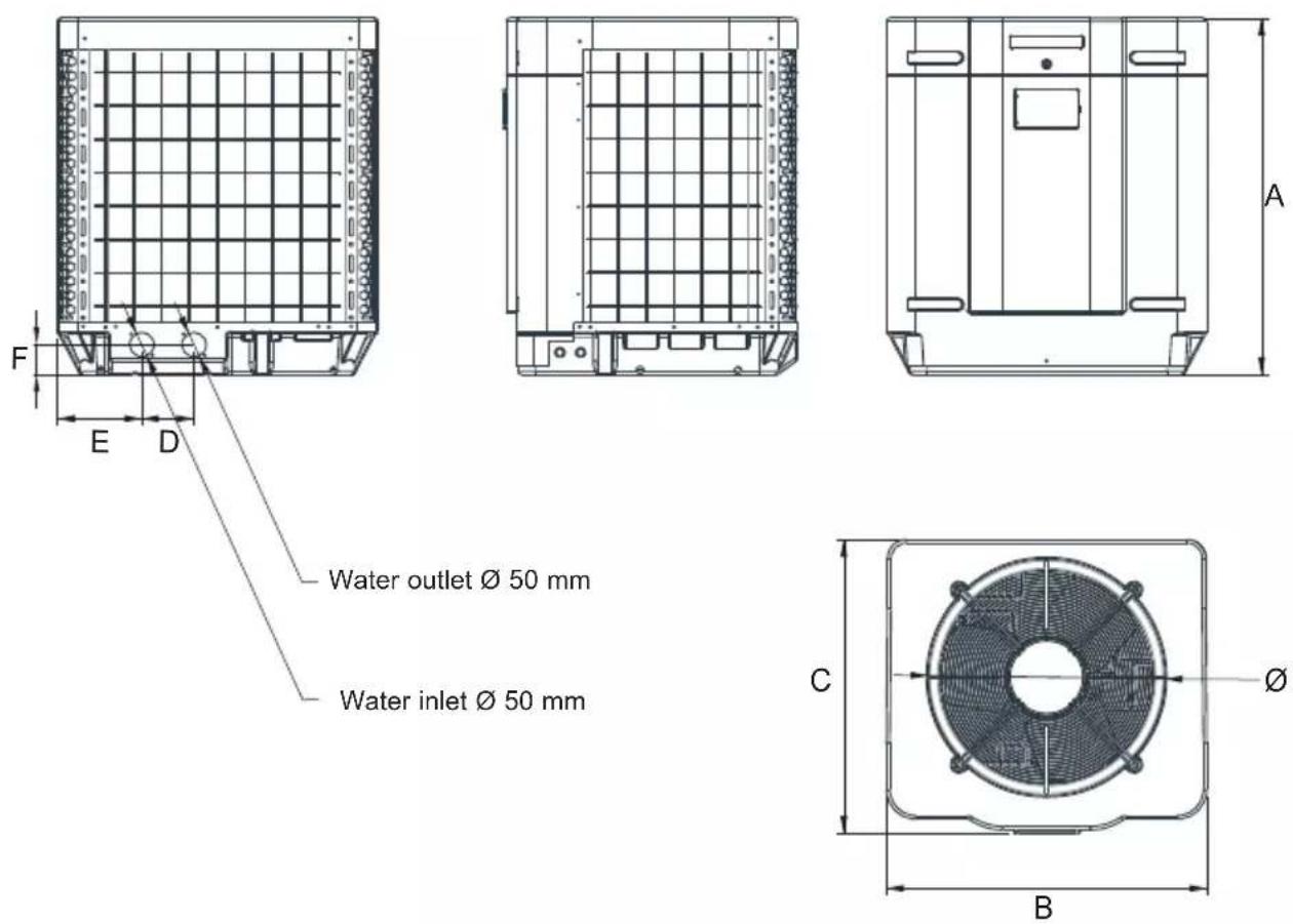
Unit: mm
| Model Mark | HP5171DT3 HP5211DT3 HP5251DT3 HP5301DT3 HP5211ET3 HP5251ET3 HP5301ET3 | ||||||
| A | 867,5 965 | 965 1024 965 | 965 1024 | ||||
| B | 730 777 | 777 920 777 | 777 920 | ||||
| C | 780 797 | 797 846 797 | 797 846 | ||||
| ∅ | 610 650 | 650 680 650 | 650 680 | ||||
| D | 120 120 | 120 150 120 | 120 150 | ||||
| E | 204 204 | 204 242 204 | 204 242 | ||||
| F | 87 85 85 | 86 85 85 86 | |||||
3. INSTALLATION AND CONNECTION
3.1 Functional Diagram
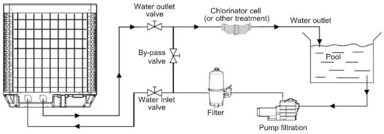
flowchart
graph TD
    A["Water inlet valve"] --> B["Water outlet valve"]
    B --> C["Chlorinator cell (or other treatment)"]
    C --> D["Water outlet"]
    D --> E["Pump filtration"]
    E --> F["Filter"]
    F --> G["By-pass valve"]
    G --> A
Note: The swimming pool heat pump unit is sold without any treatment or filtration equipment. The components presented in the diagram are spare parts to be supplied by the installer.
3. INSTALLATION AND CONNECTION (continued)
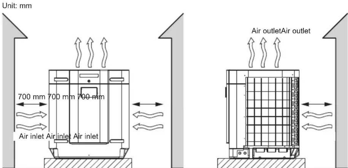
3.2 Pompe à chaleur

Place the heat pump outdoors and away from any enclosed technical space.
Choose a location that is preferably sunlit and sheltered from dominant winds.
The device must be perfectly accessible for later installation and maintenance work.
Placed under a shelter, the minimum required distances mentioned below must be respected in order to avoid any risk of air recirculation and a deficiency in the unit's overall performance.

Preferably, install the heat pump on a flat and dissociated cement block.
The maximum installation distance between the unit and the swimming pool is 15 metres.
The total length of the piping to and from the unit is 30 metres.
Insulate both the above ground and buried hydraulic piping.
The heat pump must be installed at a minimum distance from the pool in compliance with NF C 15-100 (3.5 m from the water for France) or in compliance with installation standards applicable in other countries.
Do not install the heat pump close to a heat source.
For installation in snowy regions we recommend sheltering the machine to avoid snow accumulating on the evaporator.
3. INSTALLATION AND CONNECTION (continued)
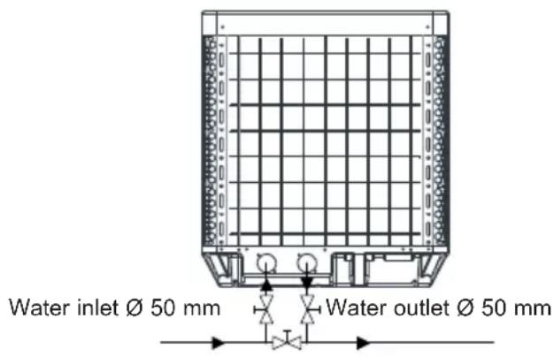
3.3 Hydraulic connection
The unit is supplied with two 50 mm ∅ union connections. Connect the water inlet to the heat pump coming from the filtration group then connect the water outlet to the heat pump at the water conduit going to the pool. Install a by-pass valve between the heat pump entrance and exit. (see diagram below).

If an automatic distributor or an electrolyser is used, it should be installed imperatively after the heat pump with the goal of protecting the titanium condenser against an elevated concentration of chemicals.

Be sure to install the by-pass valve and the supplied union connections at the water inlet and outlet level in order to simplify purging during the winter period and to facilitate access when disassembling for maintenance.
3. INSTALLATION AND CONNECTION (continued)
3.4 Electrical connection

Electrical installation and wiring for this equipment must be in conformity with local installation standards.
| F NF C15-100 GB BS7671:1992 | |||
| D D N VDE 0100-702 EW EVHS-HD 384-7-702 | |||
| A Ö VE 8001-4-702 H MSZ 2364-702/1994/MSZ 10-553 1/1990 | |||
| E U NE 20460-7-702 1993,RECBT ITC-BT-31 2002 | M MSA HD 384-7-702.S2 | ||
| IRL Wiring Rules + IS HD 384-7-702 PL PN-IEC 60364-7-702:1999 | |||
| I | CEI 64-8/7 | CZ | CSN 33 2000 7-702 |
| LUX | 384-7.702 S2 | SK | STN 33 2000-7-702 |
| NL | NEN 1010-7-702 | SLO | SIST HD 384-7-702.S2 |
| P R SIUEE TR T$ IEC 60364-7-702 | |||

Verify that the available electrical power supply and the network frequency correspond to the required operating current taking into account the appliance's specific location, and the current required to supply any other appliance connected to the same circuit.
See the corresponding wiring diagram in the appendix § 6.1.
The connection box is behind the front panel.
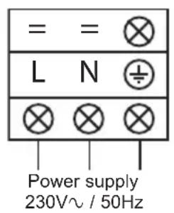
- There are three L-N-GND connections for powering single-phase models.
- Five R-S-T-N-GND connections serve for the power supply of the three-phase models.
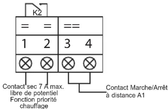
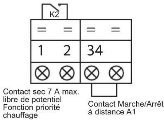
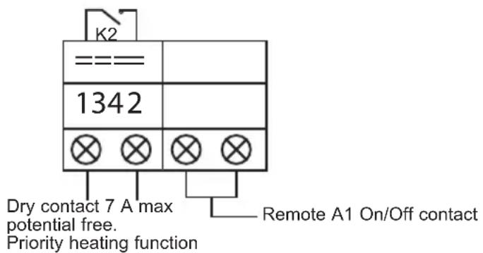
Terminals (1-2) are for controlling filter pump (K2 relay). Terminals (3-4), normally closed, are for remote on/off control.
3. INSTALLATION AND CONNECTION (continued)
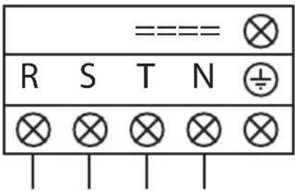
Power supply 400V 3N\~ / 50Hz
Priority heating function

Never use an electrical plug for the power supply.
The electrical power supply must have, in a suitable manner, an omnipolar protection device of the D-curve circuit breaker type as well as a 30mA protection differential circuit breaker (see following table).
| Models HP5171DT3 HP5211DT3 HP5251DT3 HP5301DT3 | |||||
| Power supply V/Ph/Hz | 230V~ 50Hz | 230V~ 50Hz | 230V~ 50Hz | 230V~ 50Hz | |
| D-Curve circuit breaker | A 16 | 20 25 25 | |||
| Cable section | mm 2 | 3G2.5 | 3G4 | 3G4 | 3G4 |
| Models | HP5211ET3 | HP5251ET3 | HP5301ET3 | |
| Power supply V/Ph/Hz | 400V 3N~ 50Hz | 400V 3N~ 50Hz | 400V 3N~ 50Hz | |
| D-Curve circuit breaker | A | 10 | 12 | 16 |
| Cable section | mm2 | 5G2.5 | 5G2.5 | 5G2.5 |

Use an RO 2V/R 2V or equivalent power cord.

The cables sections are given for a maximum length of 25 m. They must however be checked and adjusted according to the installation conditions.

Always shut down the main power supply before opening the electrical control box.
After a cut-off of the power supply, wait 10 minutes before accessing the active internal parts of the equipment (power stored in the capacitors).
3. INSTALLATION AND CONNECTION (continued)
3.5 Initial start-up
Start-up procedure - After installation is complete, follow these steps:
1) Rotate the fans by hand to verify that they can turn freely by hand, and that the turbine is correctly affixed to the motor shaft.
2) Ensure that the unit is connected correctly to the main power supply (see the wiring diagram in the appendix).
3) Activate the filtration pump.
4) Verify that all water valves are open and that the water flows toward the unit before switching on the heating or cooling mode.
5) Verify that the drainage hose is correctly affixed and that it causes no obstructions.
6) Activate the unit power supply, then press the On/Off button 📄 on the control panel.
7) Ensure that the alarm signal ( ) does not light up red. If necessary see the troubleshooting guide (see § 6.4).
8) Set the water flow using the by-pass valve (see § 3.6 and 2.1), as provided for by each model, to obtain an Entry/Exit temperature of 2° C.
9) After running for several minutes, verify that the air exiting the unit is cool (between 5 and 10°).
10) With the unit operating, turn off the filter pump. The unit should automatically turn off and display error code E03 (See § 6.4).
11) Allow the unit and the pool pump to run 24 hours per day until the desired water temperature has been reached. When the set water inlet temperature is reached, the unit will turn off. It will automatically restart (as long as the pool pump is running) if the pool temperature is at least 0.5° C below the set temperature.
Water flow switch - The unit is equipped with a flow switch that turns on the heat pump when the pool filtration pump is running, and deactivates it when the filtration pump is out of order. If the water is low, the E03 alarm code will appear on the regulator (See § 6.4).
3. INSTALLATION AND CONNECTION (continued)
Time delay - The unit is equipped with a time delay of 3 minutes in order to protect the control circuit components, to eliminate restart cycling and contactor chatter. Thanks to this time delay, the unit automatically restarts approximately 3 minutes after each control circuit interruption. Even a brief power interruption will activate the restart time delay.
3. INSTALLATION AND CONNECTION (continued)
3.6 Water flow setting
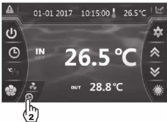
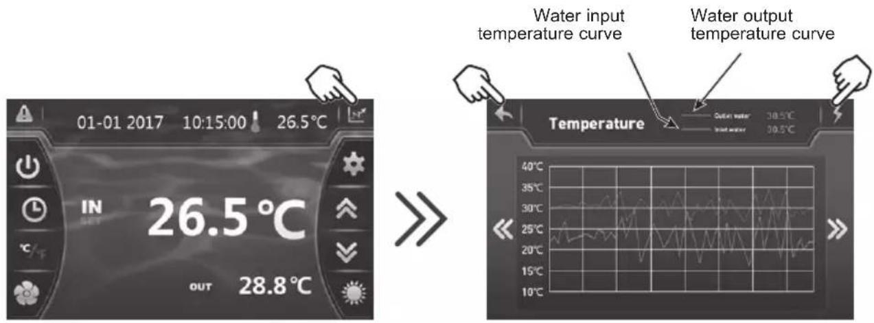
With the water entry and exit valves being open, adjust the by-pass valve in order to obtain a difference of 2°C between the inflow and outflow temperature (see principle diagram § 3.1). You can verify the switch by seeing the entry/exit temperatures directly on the control panel.
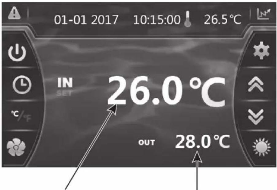
Water inlet temperature Water outlet temperature
Note: Opening the by-pass valve creates a weaker flow, which leads to an increase in ΔT .
Closing the by-pass valve creates a stronger flow, which leads to a decrease in ΔT .
4. USER INTERFACE
4.1 General presentation
The heat pump is equipped with a digital control panel with a touch screen, electronically connected and pre-set at the factory in heating mode.
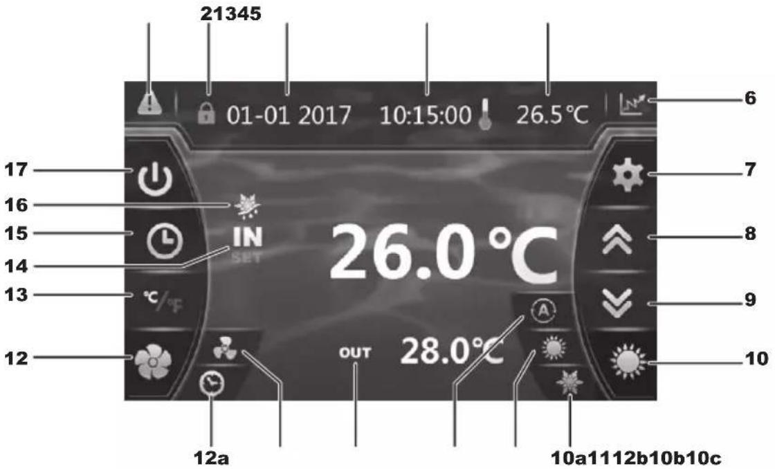
Legend
| 1 A |  | (blinking red) |
| 2 L |  | d screen |
| 3 D |  | |
| 4 H |  | |
| 5 O |  | de temperature |
| 6 |  | Recording base (Water temperature and power consumption) |
| 7 R |  | ng settings and saving |
| 8 S |  | up / Increase |
| 9 S |  | down / Decrease |
| 10 C |  | ating mode selection |
| 10a |  | ng mode |
| 10b |  | ng mode |
| 10c |  | matic mode |
| 11 W |  | Output temperature |
| 12 S |  | ting silence mode |
| 12a |  | ng silence mode timer |
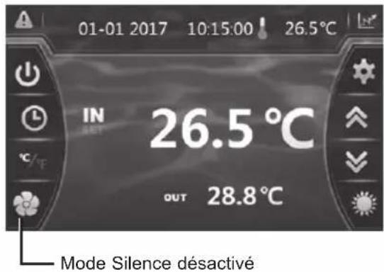
| 12b |  | Silence mode and activation light |
| 13 O |  | version °C / °F |
| 14 V |  | Input temperature |
| 15 |  | Setting the Timer date and time ON/OFF |
| 16 D |  | st mode |
| 17 O |  | Off |
4. USER INTERFACE (continued)
OFF Mode
When the heating pump is in sleep mode (OFF Mode), the button is grey.
ON Mode
When the heating pump is running or regulating (ON Mode), the button lights up green.
4.2 Setting the Date and Time
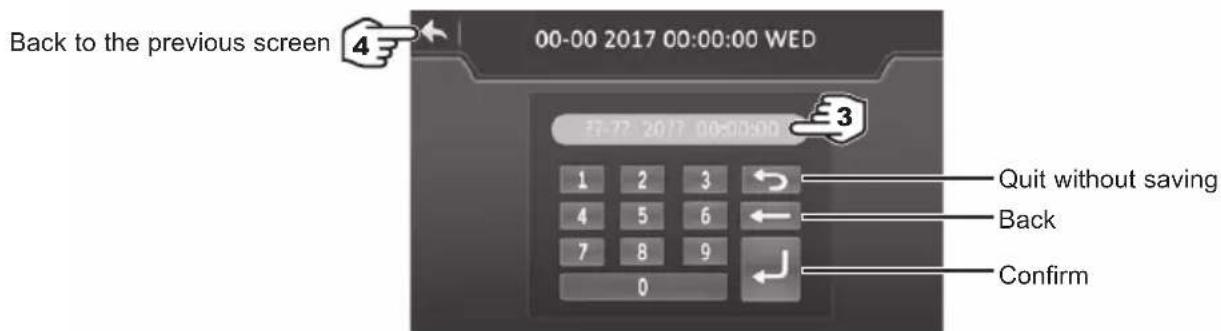

Enter all the fields (Day/Month/Year, Hour/Minute/Second before confirming, otherwise the changes will not be saved.
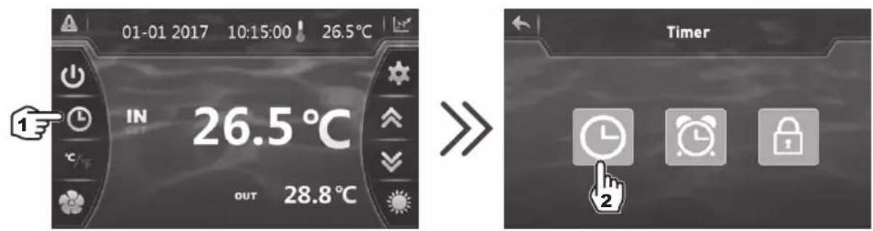
4.3 Timer function settings
Setting this function is necessary if you would like to run the heat pump for a shorter period than what is defined by the filtration clock. Therefore, you can program a deferred start and an anticipated stop or simply stop a certain timeframe from running (at night, for example).
It is possible to set one Start Timer and one Stop Timers.
4. USER INTERFACE (continued)
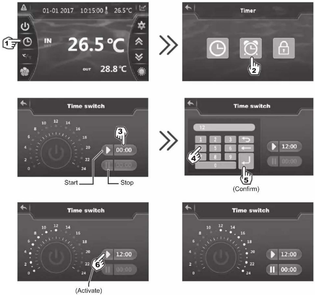

Blue highlighting = Activated
Grey = Deactivated

The setting step is "hour to hour".
- Once the start time has been set, press (step 6) to activate the Timer. The symbol and time now have blue highlighting.
- Repeat steps 3 to 6 to set and activate the stop time ( )
- When the settings are complete, the operating range of the heat pump is highlighted in green and the highlight range is yellow.
- Press twice on to return to the main screen.
4. USER INTERFACE (continued)
4.4 Setting and visualisation of the set point
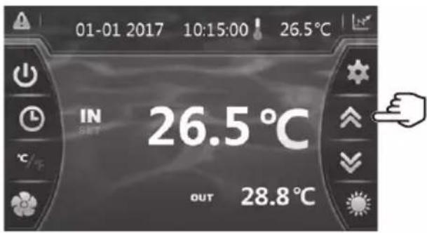
In Mode "OFF" or Mode "ON"
Press the button to display the set point, then press on pour to set the set point you wish.
Confirm by pressing and you will return to the main screen automatically.

The setting is made with a precision of 0.5°C .

It is recommended to never exceed 32° C to avoid alteration of the liners.
4. USER INTERFACE (continued)
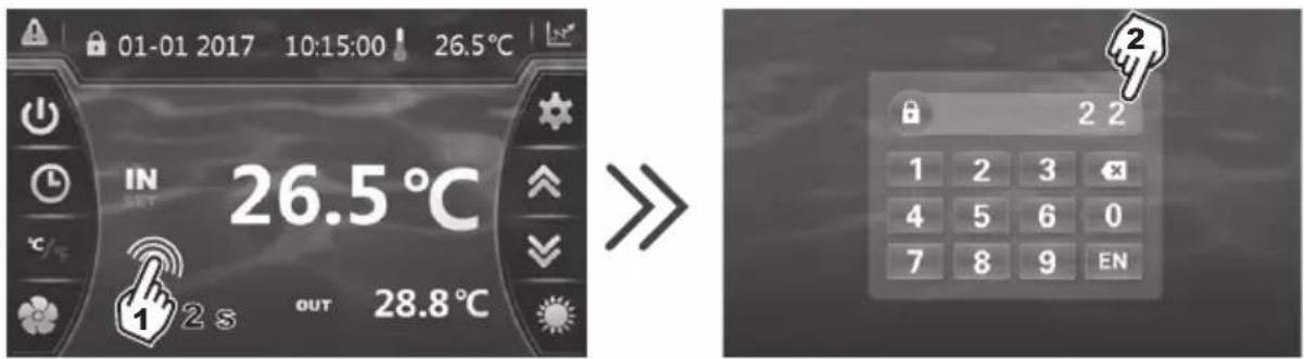
4.5 Locking and unlocking the touch screen
The control screen locks automatically after one minute (default setting). It is possible to adjust the time before the screen locks automatically to between 1 and 10 minutes, or simply to cancel this function.
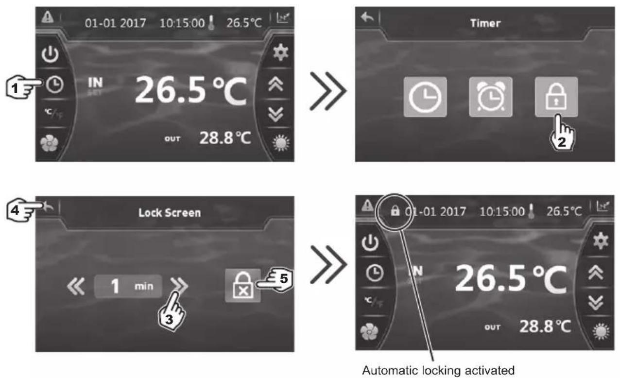
3) Set the time to between 1 and 10 minutes. Saving is automatic.
4) Press twice to return to the main screen.
5) To deactivate automatic locking press
To unlock the screen, press (anywhere) on the screen for 2s.
Enter the code "22" and confirm by pressing EN
4. USER INTERFACE (continued)
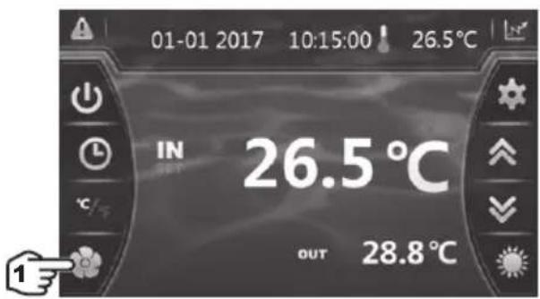
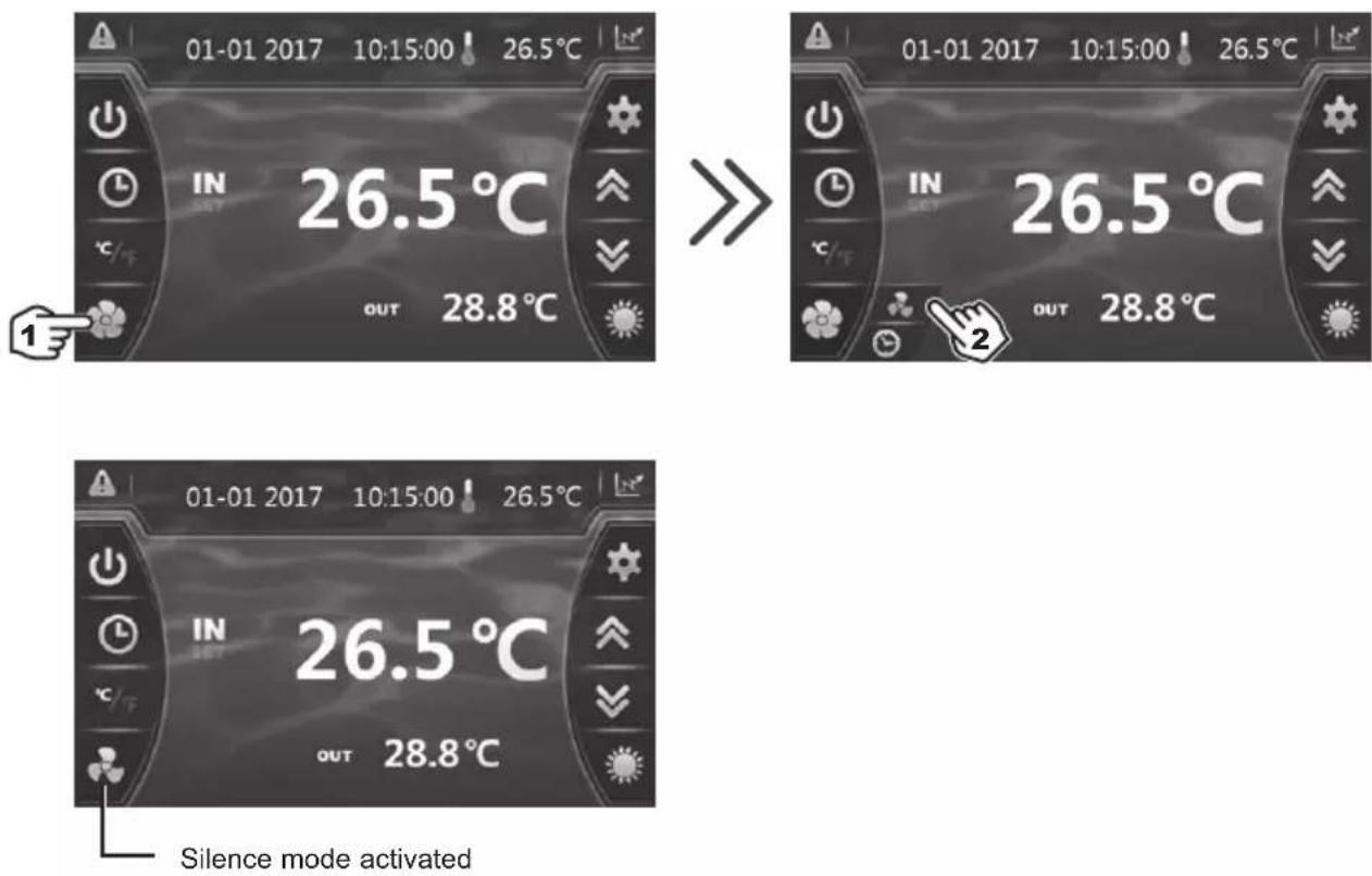
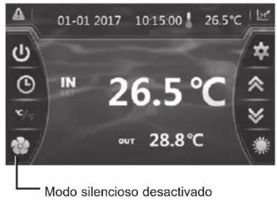
4.6 SILENT function settings
Silence mode enables the heat pump to be used in economic and very silent mode when the heating needs are low (maintaining the pool temperature or need for ultra-silent operation).
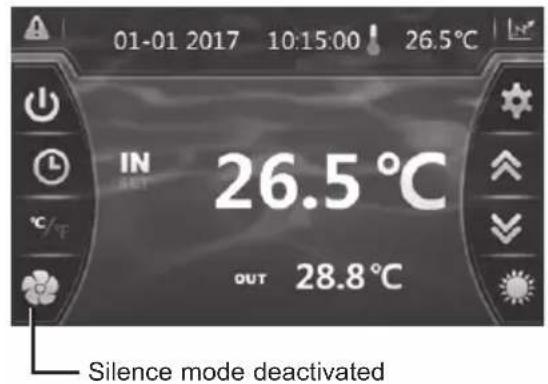
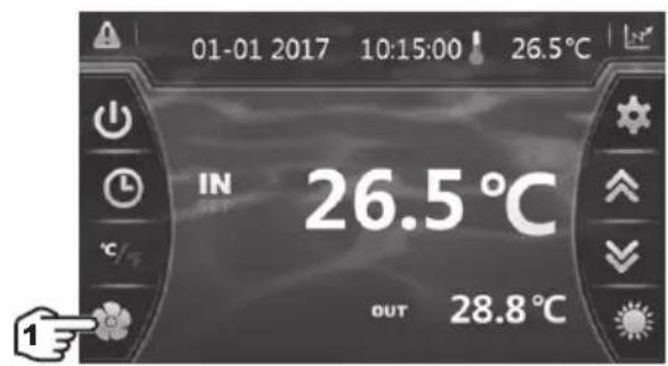
This function can be Activated/Deactivated manually or using a Timer.
Manual Activation
4. USER INTERFACE (continued)
Manual Deactivation


Setting the Timer
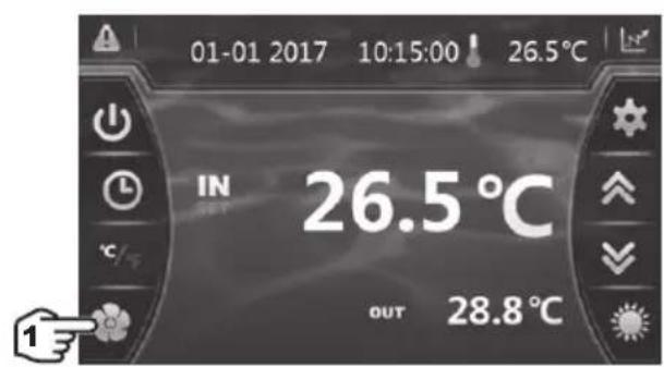

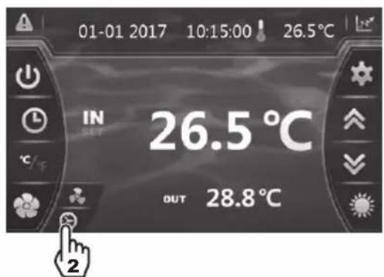
4. USER INTERFACE (continued)
Setting the Timer (continued)

1) Start time, input and confirmation.
2) End time, input and confirmation.
3) Confirm.

4) Activation.
5) Deactivation.
6) Back to the main screen.

The setting step is "hour to hour". Once the Timer is activated, it is active 7 days a week.
5.1 Maintenance
These maintenance operations must be carried out once per year in order to guarantee the longevity and the good working condition of the heat pump.
- The maintenance and repairs of the device must be carried out by an accredited professional in accordance with the regulatory texts and the rules of the art in effect in the country where the device is installed (see § 3.4).
For any intervention on the cooling circuit, the professional must hold a certificate of competence in handling refrigerants. - Check the power cable. If the power cable is damaged, it has to be replaced by the manufacturer, its after-sales service or by a qualified and authorised person.
- Verify the grounding connection of the device and its continuity.
- Clean the coil with the help of a soft brush or jet of air or water. Warning, never use a high pressure cleaner.
- Verify that the drains flow well.
- Verify the tightening of the hydraulic and electrical connections
- Verify the hydraulic sealing of the condenser.
- Have the leak-tightness of the cooling circuit to the leak detector checked by an accredited professional.

Before any maintenance operation, the heating pump must be disconnected from any electrical current source. The maintenance operations must only be carried out by personnel that is qualified and authorised to handle liquid refrigerants.
5.2 Winterising
- Put the heat pump in "OFF" mode.
- Cut the power supply to the heat pump.
- Empty the condenser with the help of the drain to avoid any risk of deterioration. (high risk of freezing).
- Close the by-pass valve and unscrew the entry/exit connection unions.
- Eliminate the maximum amount of residual stagnant water from the condenser with the help of an air gun.
- Close the water entry and exit areas of the heating pump to avoid introducing foreign bodies.
- Cover the heating pump with a dedicated winterising case.

Any damage caused by poor winterising maintenance will lead to cancellation of the warranty.
6. APPENDIX
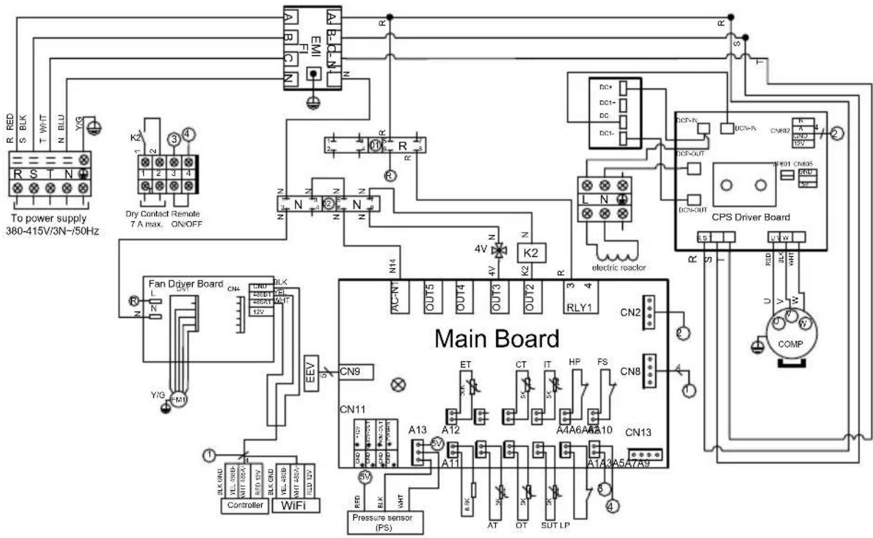
6.1 Electrical diagrams
HP5171DT3
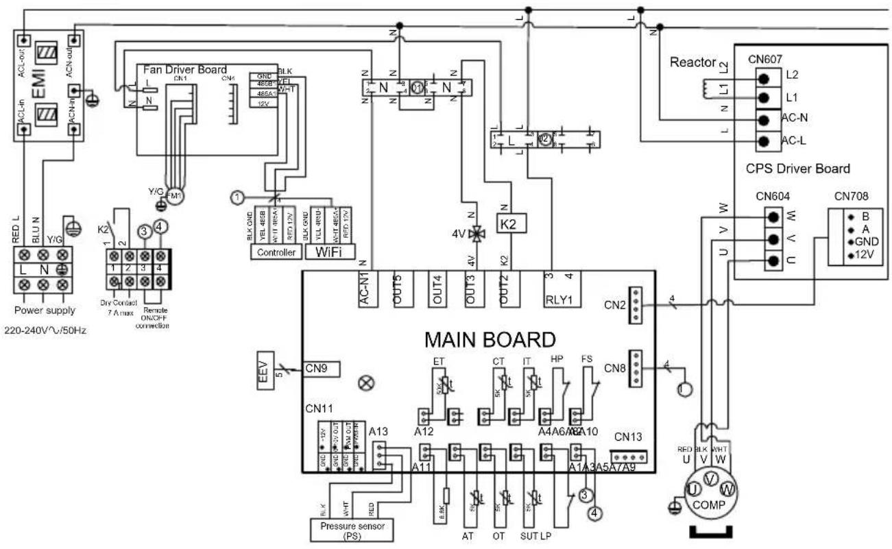
REMARKS:
PS: PRESSURE SENSOR
AT: AIR TEMPERATURE SENSOR
OT: OUTLET WATER TEMPERATURE SENSOR
SUT: SUCTION TEMPERATURE SENSOR
LP: LOW PRESSURE SWITCH
FS: WATER FLOW SWITCH
HP: HIGH PRESSURE SWITCH
IT: WATER INLET TEMPERATURE SENSOR
CT: EVAPORATOR TEMPERATURE SENSOR
ET: DISCHARGE TEMPERATURE SENSOR
EEV: ELECTRONIC EXPANSION VALVE
FM1: DC FAN MOTOR
4V: 4 WAYS VALVE
K2: DRY CONTACT 7 A MAX
COMP: COMPRESSOR
6. APPENDIX (continued)
HP5211DT3 / HP5251DT3
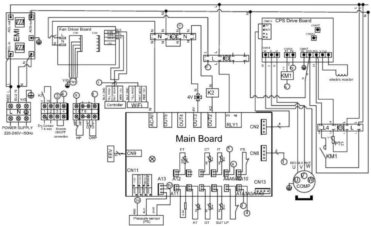
REMARKS:
PS: PRESSURE SENSOR EEV: ELECTRONIC EXPANSION VALVE
AT: AIR TEMPERATURE SENSOR
OT: OUTLET WATER TEMPERATURE SENSOR
SUT: SUCTION TEMPERATURE SENSOR
LP: LOW PRESSURE SWITCH
FS: WATER FLOW SWITCH
IT: WATER INLET TEMPERATURE SENSOR
CT: EVAPORATOR TEMPERATURE SENSOR
ET: DISCHARGE TEMPERATURE SENSOR
FM1: DC FAN MOTOR
HP: HIGH PRESSURE SWITCH
OHP: THERMAL PROTECTION
4V: 4 WAYS VALVE
K2: DRY CONTACT 7 A MAX.
PTC: THERMISTOR
KM1: COMPRESSOR SWITCH
COMP: COMPRESSOR
6. APPENDIX (continued)
HP5301DT3
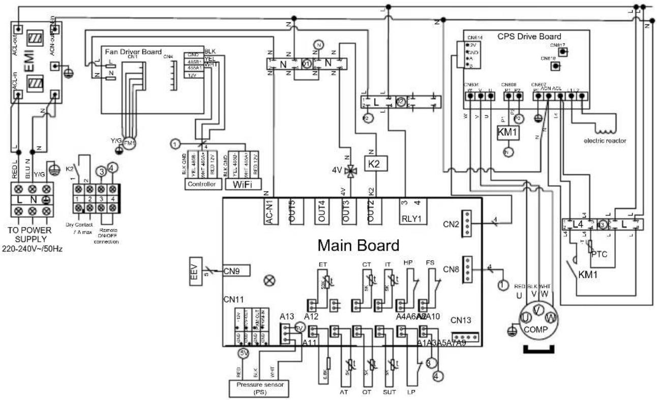
REMARKS:
PS: PRESSURE SENSOR
AT: AIR TEMPERATURE SENSOR
OT: OUTLET WATER TEMPERATURE SENSOR
SUT: SUCTION TEMPERATURE SENSOR
LP: LOW PRESSURE SWITCH
FS: WATER FLOW SWITCH
HP: HIGH PRESSURE SWITCH
IT: WATER INLET TEMPERATURE SENSOR
CT: EVAPORATOR TEMPERATURE SENSOR
ET: DISCHARGE TEMPERATURE SENSOR
EEV: ELECTRONIC EXPANSION VALVE
FM1: DC FAN MOTOR
4V: 4 WAYS VALVE
K2: DRY CONTACT 7 A MAX.
PTC: THERMISTOR
KM1: COMPRESSOR SWITCH
COMP: COMPRESSOR
6. APPENDIX (continued)
HP5211ET3 / HP5251ET3
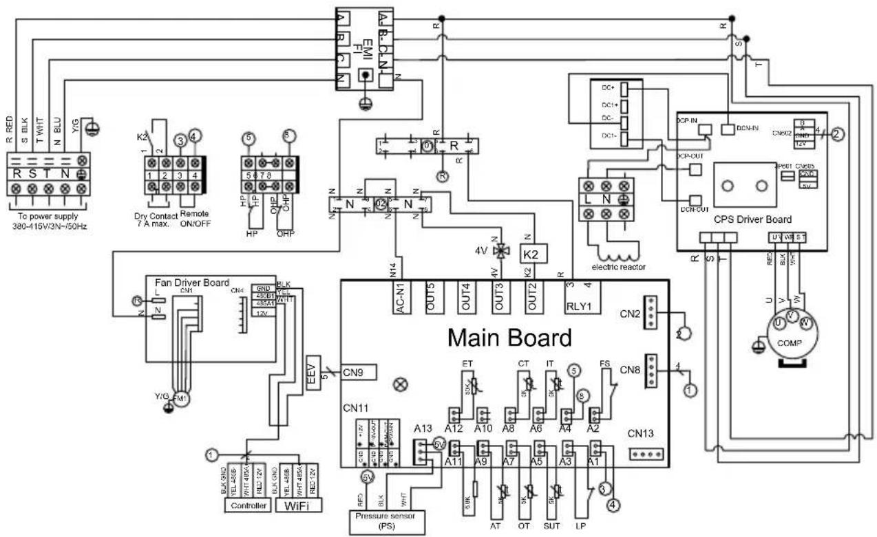
REMARKS:
PS: PRESSURE SENSOR
AT: AIR TEMPERATURE SENSOR
OT: OUTLET WATER TEMPERATURE SENSOR
SUT: SUCTION TEMPERATURE SENSOR
LP: LOW PRESSURE SWITCH OHP: THERMAL PROTECTION
FS: WATER FLOW SWITCH
IT: WATER INLET TEMPERATURE SENSOR
CT: EVAPORATOR TEMPERATURE SENSOR
ET: DISCHARGE TEMPERATURE SENSOR
EEV: ELECTRONIC EXPANSION VALVE
FM1: DC FAN MOTOR
HP: HIGH PRESSURE SWITCH
4V: 4 WAYS VALVE
K2: DRY CONTACT 7 A MAX.
COMP: COMPRESSOR
6. APPENDIX (continued)
HP5301ET3
REMARKS:
PS: PRESSURE SENSOR
AT: AIR TEMPERATURE SENSOR
OT: OUTLET WATER TEMPERATURE SENSOR
SUT: SUCTION TEMPERATURE SENSOR
LP: LOW PRESSURE SWITCH
FS: WATER FLOW SWITCH
HP: HIGH PRESSURE SWITCH COMP: COMPRESSOR
IT: WATER INLET TEMPERATURE SENSOR
CT: EVAPORATOR TEMPERATURE SENSOR
ET: DISCHARGE TEMPERATURE SENSOR
EEV: ELECTRONIC EXPANSION VALVE
FM1: DC FAN MOTOR
4V: 4 WAYS VALVE
K2: DRY CONTACT 7 A MAX.
Page left intentionally blank
6. APPENDIX (continued)
6.2 Heating priority wiring for monophasic pump

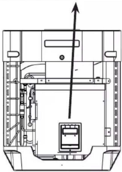
Remove the front panel to access the terminal board.
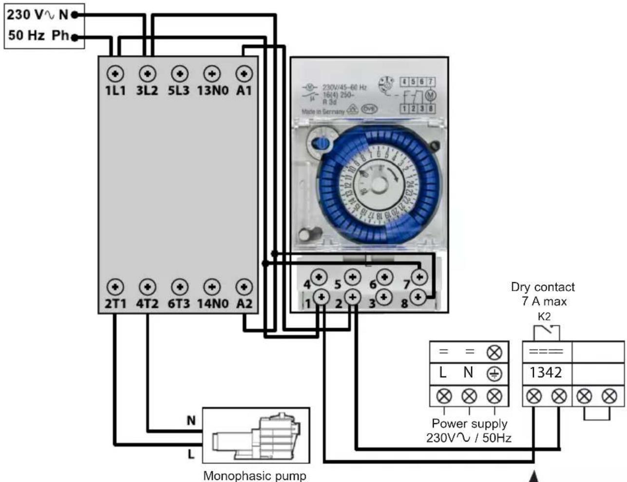
Terminals 1 and 2 deliver a potential-free dry contact, 230V\~ / 50 Hz, no polarity.
Wire terminals 1 and 2 as indicated in the diagram above, to activate the operation of the filtration pump in 2-minute cycles each hour if the temperature of the pool is lower than the set point.

Never connect the power supply of the filtration up directly to terminals 1 and 2.
natural_image
Technical line drawing of a mechanical device with internal components and an upward arrow indicator (no text or symbols)6. APPENDIX (continued)
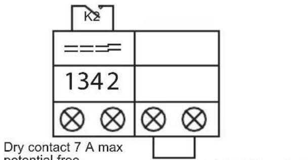
6.3 Heating priority wiring for three phases pump

Remove the front panel to access the terminal board.
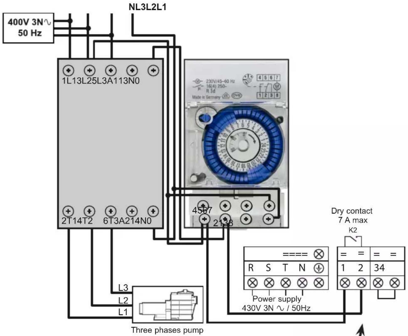
Terminals 1 and 2 deliver a potential-free dry contact, 230V\~ / 50 Hz, no polarity.
Wire terminals 1 and 2 as indicated in the diagram above, to activate the operation of the filtration pump in 2-minute cycles each hour if the temperature of the pool is lower than the set point.
natural_image
Technical line drawing of a mechanical assembly with internal components and an upward arrow indicator (no text or symbols)
Never connect the power supply of the filtration gap directly to terminals 1 and 2.
6. APPENDIX (continued)
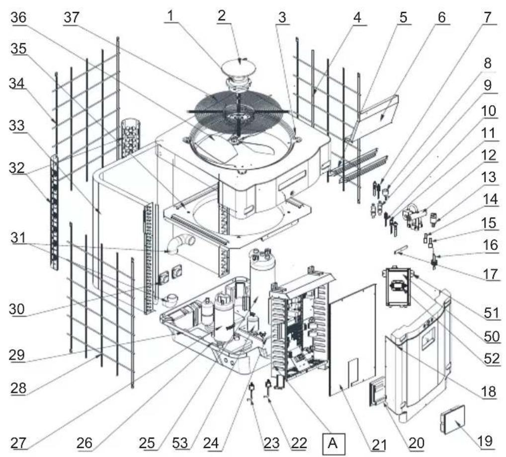
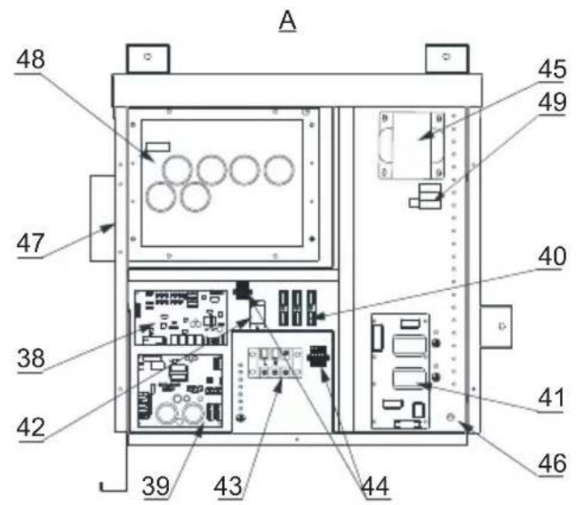
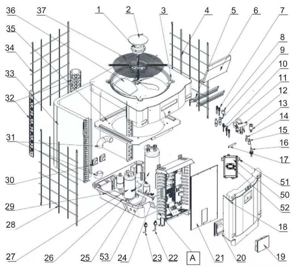
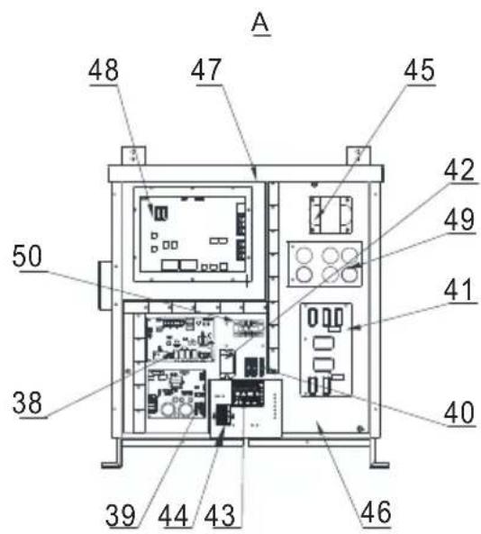
6.4 Exploded view and spare parts
HP5171DT3 / HP5211DT3 / HP5251DT3 / HP5301DT3

HP5171DT3 / HP5211DT3 / HP5251DT3 / HP5301DT3
| Mark | Description P/N | HP5171DT3 | HP5211DT3 | HP5251DT3 | HP5301DT3 | |
| 1 Fan Motor | HWX20000330381 | √ | √ | n/a | ||
| HWX20000330402 n/a | n/a | n/a | √ | |||
| 2 Motor cover HWX20000220320 | √ | √ | √ | |||
| 3 ABS upper panel | HWX80900736 | √ | n/a | n/a | ||
| HWX80900737 n/a | √ | √ | n/a | |||
| HWX80900718 n/a | n/a | n/a | √ | |||
| 4 Right-hand lateral protection | HWX80704158 | √ | n/a | n/a | ||
| HWX80705113 n/a | √ | √ | n/a | |||
| HWX80705110 n/a | n/a | n/a | √ | |||
| 5 | / / / / | / / | ||||
| 6 Guard plate | HWX32012210724 | √ | n/a | n/a | ||
| HWX32002210071 n/a | √ | √ | n/a | |||
| HWX32004210137 n/a | n/a | n/a | √ | |||
| 7 | Pressure tap 90 mm 1/2" | HWX20000140153 | √ | √ | √ | |
| 8 | Electronic expansion valve | HWX20000140451 | √ | n/a | n/a | |
| HWX20000140449 n/a | √ | n/a | n/a | |||
| HWX20000140442 n/a | n/a | n/a | √ | |||
| HWX20000140401 n/a | n/a | n/a | √ | |||
| 9 | Filter ∅12.9-∅12.9 (∅28) | HWX20000140027 | √ | √ | √ | |
| 10 | Pressure Tap 95 mm 7/16" | HWX20000140512 | √ | √ | √ | |
| 11 | Pressure Tap 40 mm 1/2" | HWX20000140150 | √ | √ | √ | |
| 12 | 4 ways valve | HWX20041437 | √ | n/a | n/a | |
| HWX20011491 n/a | √ | √ | √ | |||
| 13 | Pressure sensor | HWX20000360274 | √ | √ | √ | |
| 14 | Coil/air/water temp sensor 5k-800 mm | HWX20003202 | √ | √ | √ | |
| 15 | Compressor discharge probe 50k-600 mm | HWX20000320145 | √ | √ | √ | |
| 16 | Water flow detector | HWX83000069 | √ | √ | √ | |
| 17 | / / / / | / / | ||||
| 18 | Front panel | HWX80900738 | √ | n/a | n/a | |
| HWX80900739 n/a | √ | √ | n/a | |||
| HWX80900710 n/a | n/a | n/a | √ | |||
| 19 | Color touchscreen | HWX95005310612 | √ | √ | √ | |
| 20 | Black electric access hatch | HWX20000220247 | √ | √ | √ | |
| 21 | Electrical box cover | HWX80702647 | √ | n/a | n/a | |
| HWX80702644 n/a | √ | √ | n/a | |||
| HWX80702645 n/a | n/a | n/a | x | |||
| 22 | High pressure switch NC 3.2MPa/4.4MPa | HWX20000360187 | √ | √ | √ | |
| 23 | Low pressure switch NO 0.15MPa/0.05MPa | HWX20000360054 | √ | √ | √ | |
| 24 | / / / / | / / | ||||
| 25 | Titanium/PVC condenser | HWX32009120085 | √ | n/a | n/a | |
| HWX32002120023 n/a | √ | n/a | n/a | |||
| HWX32016120012 n/a | n/a | n/a | √ | |||
| HWX32016120011 | n/a | n/a | n/a | |||
| 26 | / / / / | / / | ||||
| 27 | Compressor | HWX80100046 | √ | n/a | n/a | |
| HWX80100069 n/a | √ | √ | n/a | |||
| HWX30101000006 n/a | n/a | n/a | √ | |||
| 28 | Left-hand lateral protection | HWX32012210729 | √ | n/a | n/a | |
| HWX80705114 n/a | √ | √ | n/a | |||
| HWX80705111 | n/a | n/a | n/a | |||
6. APPENDIX (continued)
HP5171DT3 / HP5211DT3 / HP5251DT3 / HP5301DT3


6. APPENDIX (continued)
HP5171DT3 / HP5211DT3 / HP5251DT3 / HP5301DT3
| Mark | Description P/N | HP5171DT3 | HP5211DT3 | HP5251DT3 | HP5301DT3 | |
| 29 | ////// | |||||
| 30 | Square 50 mm threaded connector HWX20031379 | ✓ ✓ | ✓ ✓ | |||
| 31 | PVC elbow ∅ 50 mm HWX20011359 | ✓ ✓ | ✓ ✓ | |||
| 32 | Left/right vertical support | HWX32000210086 | ✓ | n/a n/a n/a | ||
| HWX80702346 n/a | ✓ | ✓ | n/a | |||
| HWX80702656 n/a | n/a n/a | ✓ | ||||
| 33 | Fin coil | HWX32012120155 | ✓ | n/a n/a n/a | ||
| HWX80600429 n/a | ✓ | n/a n/a | ||||
| HWX32003120028 | n/a n/a | ✓ | n/a | |||
| HWX32004120013 | n/a n/a n/a | ✓ | ||||
| 34 | Rear protection | HWX32012210730 | ✓ | n/a n/a n/a | ||
| HWX80705115 | n/a | ✓ | ✓ | n/a | ||
| HWX80705112 | n/a n/a n/a | ✓ | ||||
| 35 | ////// | |||||
| 36 | Fan blade ∅ 522 mm | HWX20000270062 | ✓ | n/a n/a n/a | ||
| Fan blade ∅ 560 mm | HWX35072195 n/a | ✓ | ✓ | n/a | ||
| Fan blade ∅ 600 mm | HWX20000270057 | n/a | n/a | n/a | ✓ | |
| 37 | Fan protection grille | HWX32012210732 | ✓ | n/a n/a n/a | ||
| HWX32003210142 | n/a | ✓ | ✓ | n/a | ||
| HWX80700160 n/a | n/a n/a | ✓ | ||||
| 38 | Motherboard | HWX72200033171D | ✓ | n/a n/a n/a | ||
| HWX72200033211D | n/a | ✓ | n/a n/a | |||
| HWX72200033251D | n/a n/a | ✓ | n/a | |||
| HWX72200033301D | n/a n/a n/a | ✓ | ||||
| 39 | Ventilator Inverter card | HWX82300485 | ✓ ✓ | ✓ ✓ | ||
| 40 | Terminal block 4 connections | HWX20003909 | ✓ ✓ | ✓ ✓ | ||
| 41 | Filter board | HWX3020100007 | ✓ ✓ | ✓ ✓ | ||
| 42 | K2 relay | HWX20000360297 | ✓ ✓ | ✓ ✓ | ||
| 43 | Terminal block L-N-GND | HWX20000390223 | ✓ ✓ | ✓ ✓ | ||
| 44 | 4-position terminal block | HWX20000390046 | ✓ ✓ | ✓ ✓ | ||
| 45 | Reactance coil | HWX82500009 | ✓ | n/a n/a n/a | ||
| HWX20000370030 | n/a | ✓ ✓ | ✓ | |||
| 46 | ///// | |||||
| 47 | ///// | |||||
| 48 | Compressor Inverter card | HWX82300149 | ✓ | n/a n/a n/a | ||
| HWX82300019 n/a | ✓ ✓ | ✓ | ||||
| 49 | PTC 100 Ω resistor HWX20000320113 n/a | ✓ ✓ | ✓ | |||
| 50 | ///// | |||||
| 51 | ///// | |||||
| 52 | Power switch | HWX200003600619 | n/a | ✓ ✓ | ✓ | |
| 53 | Bottle of liquid | HWX20000140579 | n/a | n/a | ✓ | ✓ |
6. APPENDIX (continued)
HP5211ET3 / HP5251ET3 / HP5301ET3

HP5211ET3 / HP5251ET3 / HP5301ET3
| Mark | Description P/N HP5211ET3 HP5251ET3 HP5301 | ET3 | |||
| 1 DC Fan Motor | HWX20000330381 | √ | √ | n/a | |
| HWX20000330402 n/a | n/a | √ | |||
| 2 Motor cover HWX20000220320 | √ √ | √ | |||
| 3 | Upper panel | HWX80900737 | √ | √ | n/a |
| HWX80900718 n/a n/a | √ | ||||
| 4 | Right-hand lateral protection | HWX80705113 | √ | √ | n/a |
| HWX80705110 n/a n/a | √ | ||||
| 5 / / / / | |||||
| 6 Guard plate | HWX32002210071 | √ | √ | n/a | |
| HWX32004210137 n/a | n/a | √ | |||
| 7 Pressure tap 90 mm 1/2" | HWX20000140153 | √ √ | √ | ||
| 8 Electronic expansion valve | HWX20000140449 | √ | n/a | n/a | |
| HWX20000140442 n/a | √ | n/a | |||
| HWX20000140401 n/a | n/a | √ | |||
| 9 | Filter ∅12.9-∅12.9 (∅28) | HWX20000140027 | √ √ | √ | |
| 10 | Pressure Tap 95 mm 7/16" | HWX20000140512 | √ √ | √ | |
| 11 | Pressure Tap 40 mm 1/2" | HWX20000140150 | √ √ | √ | |
| 12 | 4 ways valve | HWX20011491 | √ √ | √ | |
| 13 | Pressure sensor | HWX20000360274 | √ √ | √ | |
| 14 | Coil/air/water temp sensor 5k-800 mm | HWX20003202 | √ √ | √ | |
| 15 | Compressor discharge probe 50k-600 mm | HWX20000320145 | √ √ | √ | |
| 16 | Water flow detector | HWX83000069 | √ √ | √ | |
| 17 | / / / / / | ||||
| 18 | Front panel | HWX80900739 | √ | √ | n/a |
| HWX80900710 n/a n/a | √ | ||||
| 19 | Color touchscreen | HWX95005310612 | √ √ | √ | |
| 20 | Black electric access hatch | HWX20000220247 | √ √ | √ | |
| 21 | Electrical box cover | HWX80702644 | √ | √ | n/a |
| HWX80702645 n/a n/a | √ | ||||
| 22 | High pressure switch NC 3.2MPa/4.4MPa | HWX20000360187 | √ √ | √ | |
| 23 | Low pressure switch NO 0.15MPa/0.05MPa HWX20000360054 | √ √ | √ | ||
| 24 | / / / / / | ||||
| 25 | Condenseur Titane PVC | HWX32002120023 | √ | n/a | n/a |
| HWX32016120012 n/a | √ | n/a | |||
| HWX32016120011 | n/a n/a | √ | |||
| 26 | / / / / / | ||||
| 27 | Compressor | HWX80100069 | √ | √ | n/a |
| HWX30101000006 n/a | n/a | √ | |||
| 28 | Left-hand lateral protection | HWX80705114 | √ | √ | n/a |
| HWX80705111 | n/a n/a | √ | |||
| 29 | / / / / / | ||||
| 30 | Square 50 mm threaded connector | HWX20031379 | √ √ | √ | |
| 31 | PVC elbow ∅ 50 mm | HWX20011359 | √ √ | √ | |
| 32 | Left/right vertical support | HWX80702346 | √ | √ | n/a |
| HWX80702656 n/a n/a x | |||||
| 33 | Fin coil | HWX80600429 | √ | n/a | n/a |
| HWX32003120028 n/a | √ | n/a | |||
| HWX32004120013 n/a | n/a | √ | |||
| 34 | Protection arrière | HWX80705115 | √ | √ | n/a |
| HWX80705112 n/a n/a | √ | ||||
6. APPENDIX (continued)
HP5211ET3 / HP5251ET3 / HP5301ET3


6. APPENDIX (continued)
HP5211ET3 / HP5251ET3 / HP5301ET3
| Mark | Description P/N HP5211ET3 HP5251ET3 HP5301 | ET3 | |||
| 35 / | / / / / | ||||
| 36 | Fan blade ∅ 560 mm HWX35072195 | √ | √ | n/a | |
| Fan blade ∅ 600 mm HWX20000270057 n/a | n/a | √ | |||
| 37 F | Fan protection grille | HWX32003210142 | √ | √ | n/a |
| HWX80700160 | n/a | n/a | √ | ||
| 38 | Motherboard | HWX72200033211E | √ | n/a | n/a |
| HWX72200033251E | n/a | √ | n/a | ||
| HWX72200033301E | n/a | n/a | √ | ||
| 39 | Ventilator Inverter card | HWX82300485 | √ | √ | √ |
| 40 | Terminal block 4 connections | HWX20003909 | √ | √ | √ |
| 41 | Filter board | HWX82300074 | √ | √ | √ |
| 42 | K2 relay | HWX20000360297 | √ | √ | √ |
| 43 | Terminal block L-N-GND | HWX20000390180 | √ | √ | √ |
| 44 | 4-position terminal block | HWX20000390046 | √ | √ | √ |
| 45 | Reactance coil | HWX20000370030 | √ | √ | √ |
| 46 / | / / / / | ||||
| 47 / | / / / / | ||||
| 48 | Compressor Inverter card | HWX82300112 | √ | √ | n/a |
| HWX302010000012 | n/a | n/a | √ | ||
| 49 | Capacitor board | HWX302010000014 | √ | √ | √ |
| 50 | L-N-GND reactance terminal board | HWX20000390223 | √ | √ | √ |
| 51 | Bottle of liquid | HWX20000140579 n/a | √ | √ |
6. APPENDIX (continued)
6.5 Troubleshooting guide

Certain operations must be carried out by an authorized technician.
If there is a fault on the heat pump, the symbol 🔍 appears blinking red in the left hand corner of the screen.
Press the symbol 🔍 to access the list of errors.
Refer to following table.
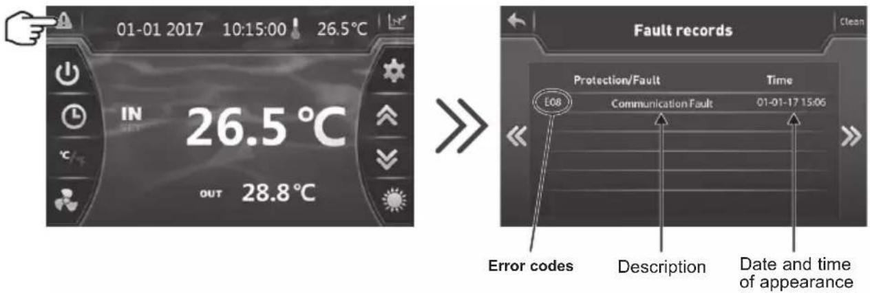

Once the problem has been resolved the error is cancelled automatically and the triangle changes to solid grey.

To delete the error list, press on then return to the previous screen by pressing on
6. APPENDIX (continued)
| Problem | Error codes | Description Solution | |
| Water inlet sensor fault P01 | The sensor is open or has short-circuited. | Check the blue AIN6 connector on the board and measure the sensor's resistance; if it is under 100 Ω or over 500 kΩ, replace it. | |
| Water outlet sensor fault P02 | Check the red AIN7 connector on the board and measure the sensor's resistance; if it is under 100 Ω or over 500 kΩ, replace it. | ||
| Outside temperature sensor fault P04 | Check the AIN9 connector on the board and measure the sensor's resistance; if it is under 100 Ω or over 500 kΩ, replace it. | ||
| De-icing sensor fault P05 | Check the yellow AIN8 connector on the board and measure the sensor's resistance; if it is under 100 Ω or over 500 kΩ, replace it. | ||
| Compressor aspiration sensor defect | P07 | Check the green AIN5 connector on the board and measure the sensor's resistance; if it is under 100 Ω or over 500 kΩ, replace it. | |
| Resistance fault 6.8 kΩ P09 | Check the AIN11 connector on the board and measure the resistance; replace it if R < 6.8 kΩ | ||
| Compressor discharge sensor fault P081 | Check the black AIN12 connector on the board and measure the sensor's resistance; if it is under 100 Ω or over 500 kΩ, replace it. | ||
| Discharge temperature too high P082 | Discharge temperature > 120°C | Measure the discharge temperature at the outlet of the compressor; if measured temperature < 120°C, replace the sensor. Perform a non-condensable test | |
| High pressure protection E01 The sensor is open or has short-circuited. | Verify the AIN4 connectors on the card or replace the sensor | ||
| Check the water flow | |||
| Check the water flow detector | |||
| Check the valve opening | |||
| Check the by-pass | |||
| Check the evaporator is not clogged | |||
| Water temperature too hot | |||
| Incondensable problem after maintenance, empty and evacuate the cooling circuit | |||
| Fluid load too high, remove fluid into a liquid bottle | |||
| Low pressure protection E02 The sensor is open or has short-circuited. | Check the AIN3 connections on the card or replace the sensor | ||
| Large coolant leak, search for the leak with the detector | |||
| Air flow too low, check the ventilator rotation speed | |||
| Check the evaporator is not clogged, clean its surface | |||
6. APPENDIX (continued)
| Problem | Error codes | Description Solution | |
| Flow sensor fault E03 The sensor is open or has short-circuited. | Check the AIN2 connections on the card or replace the sensor | ||
| Lack of water, check the filtration pump operation | |||
| Check the stop valve opening | |||
| Check the by-pass adjustment | |||
| Water outlet temperature fault E05 | Applies only in Cold mode, Water outlet temperature < 4°C | Stop the heat pump, serviceability limit reached | |
| Input/Output temperature difference >13°C | E06 | Applicable in Cold mode only | Lack of water, check the filtration pump operation |
| Check the stop valve opening | |||
| Check the by-pass adjustment | |||
| Antifreeze protection Cold mode E07 | Water output temperature < 4°C | Check the red AIN7 connector on the board and measure the sensor's resistance; if it is under 100 Ω or over 500 kΩ, replace it. | |
| Stop the heat pump, drain the condenser, high risk of it freezing. | |||
| Communication problem E08 | No communication between the printed circuit board and the user interface | Check the connectors - see the wiring diagram | |
| Level 1 antifreeze protection E19 | 2°< Water temperature < 4° and Air temperature < 0° | Stop heat pump operation, empty the condenser to avoid freezing, by default the heat pump starts the filtration pump to avoid icing over | |
| Level 2 antifreeze protection E29 | Water temperature < 2° and Air temperature < 0° | Stop heat pump operation, empty the condenser to avoid freezing, by default the heat pump starts the filtration pump and the heat pump to avoid icing over. | |
| DC1 fan motor fault F031 Motor jammed or faulty connection | Check free rotation; check CN1 connectors; replace the motor | ||
| The heat pump does not start F08 Possibly an inversion or lack of phase | Reverse two phases on the R-S-T terminal block.Check the connection and tightness of the phases. | ||
| Exterior temperature too low TP | Outdoor temperature too low, < H34 (-15°C fault) | Check the AIN9 connector on the board and measure the sensor's resistance; if it is under 100 Ω or over 500 kΩ, replace it. | |
| Check the value of parameter H34 | |||
| Pressure sensor fault PP The sensor is open or short-circuiting | Check the connections see electrical diagram | ||
6. APPENDIX (continued)
6.6 Recording base
From the main screen, press on 📄 to access the history of water input and output temperature recordings.

This data is available for 60 days.
Press on to access the compressor frequency.
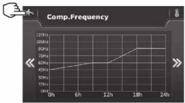
line
Comp.Frequency | Time | Comp.Frequency (Hz) | |---|---| | 0h | 45 | | 6h | 55 | | 12h | 60 | | 18h | 90 | | 24h | 90 |Press on to return to the main screen.
WARRANTY CONDITIONS
All HAYWARD products are guaranteed to be free from manufacturing or material faults for a period of two years as from the date of purchase. Any claim made under the terms of the warranty must be accompanied by a dated proof of purchase. We therefore recommend that you keep your invoice.
The HAYWARD warranty is limited to the repair or replacement, at HAYWARD's discretion, of faulty products, provided they have been used under normal conditions, as described in their user guide, and that the product has not been modified in any way and has been used only with HAYWARD components and parts. Frost and chemical damage are not covered.
No other costs (transportation, labour, etc.) are covered by the warranty.
HAYWARD cannot be held liable for any direct or indirect damage caused by the incorrect installation, connection or operation of a product.
Please contact your retailer if you want to make a claim under the terms of the warranty and request the repair or replacement of an item. No equipment returned to our factory will be accepted without our prior written agreement.
Worn parts are not covered by the warranty.
6.7 End of life of the device

The symbol of the crossed-out dustbin concerning the treatment and the reclamation of electrical and electronic waste means that the products must not be disposed of with household waste, bulky items or in a landfill under no circumstances.
At the end of life, the device must undergo selective collection so that it can be recycled or reclaimed. A specific circuit for recovering this type of products is set up in the countries of the European Union and in Norway.
Contact the installer or the local representative to have this device collected, dismantled and recycled.
Retreating the refrigerant, oil and other parts has to be carried out by a qualified accredited professional in accordance with current local and national legislation.
If the product contains batteries that bear this symbol, this means that the batteries can contain harmful or polluting substances. In this case, take the batteries to a used battery collection point.
SUMHEAT FULL INVERTER
UNIDAD DE BOMBA DE CALOR PARA PISCINAS

natural_image
Exterior view of a modern industrial water filter unit (no visible text or symbols)
HP5171DT3 HP5211DT3 HP5251DT3 HP5301DT3 HP5211ET3 HP5251ET3 HP5301ET3
LEYENDA
natural_image
Technical line drawing of a mechanical device with internal components and an upward arrow indicator (no text or symbols)natural_image
Technical line drawing of a mechanical device with internal components and an upward arrow indicator (no text or symbols)
HP5171DT3 / HP5211DT3 / HP5251DT3 / HP5301DT3
| Rep | Designación Ref. | HP5171DT3 | HP5211DT3 | HP5251DT3 | HP5301DT3 | |
| 1 | Motor ventilador CC | HWX20000330381 | √ | √ | n/a | |
| HWX20000330402 n/a | n/a | n/a | √ | |||
| 2 | Capós de protección del motor HWX20000220320 | √ | √ | √ | ||
| 3 | Panel superior ABS | HWX80900736 | √ | n/a | n/a | |
| HWX80900737 n/a | √ | √ | n/a | |||
| HWX80900718 n/a | n/a | n/a | √ | |||
| 4 | Protección lateral derecha | HWX80704158 | √ | n/a | n/a | |
| HWX80705113 n/a | √ | √ | n/a | |||
| HWX80705110 n/a | n/a | n/a | √ | |||
| 5 | / / / / / / | |||||
| 6 | Placa de protección | HWX32012210724 | √ | n/a | n/a | |
| HWX32002210071 n/a | √ | √ | n/a | |||
| HWX32004210137 n/a | n/a | n/a | n/a | |||
| 7 | Toma de presión de 90 mm - 1/2" | HWX20000140153 | √ | √ | √ | |
| 8 | Arrancador electrónico | HWX20000140451 | √ | n/a | n/a | |
| HWX20000140449 n/a | √ | n/a | n/a | |||
| HWX20000140442 n/a | n/a | n/a | √ | |||
| HWX20000140401 n/a | n/a | n/a | n/a | |||
| 9 | Filtro ∅12.9-∅12.9 (∅28) | HWX20000140027 | √ | √ | √ | |
| 10 | Toma de presión 95 mm - 7/16" | HWX20000140512 | √ | √ | √ | |
| 11 | Toma de presión 40 mm - 1/2" | HWX20000140150 | √ | √ | √ | |
| 12 | Válvula 4 vías | HWX20041437 | √ | n/a | n/a | |
| HWX20011491 n/a | √ | √ | √ | |||
| 13 | Sensor de presión | HWX20000360274 | √ | √ | √ | |
| 14 | Sonda de temperatura Evap/aire/agua 5k 800mm | HWX20003202 | √ | √ | √ | |
| 15 | Sonda de descarga compresor 50k-600 mm | HWX20000320145 | √ | √ | √ | |
| 16 | Detector del caudal de agua | HWX83000069 | √ | √ | √ | |
| 17 | / / / / / / | |||||
| 18 | Panel delantero | HWX80900738 | √ | n/a | n/a | |
| HWX80900739 n/a | √ | √ | n/a | |||
| HWX80900710 n/a | n/a | n/a | √ | |||
| 19 | Pantalla táctil en color | HWX95005310612 | √ | √ | √ | |
| 20 | Trampilla de acceso eléctrico | HWX20000220247 | √ | √ | √ | |
| 21 | Panel de caja eléctrica | HWX80702647 | √ | n/a | n/a | |
| HWX80702644 n/a | √ | √ | n/a | |||
| HWX80702645 n/a | n/a | n/a | x | |||
| 22 | Presostato de alta presión NC 3.2 MPa/4.4MPa | HWX20000360187 | √ | √ | √ | |
| 23 | Presostato baja presión NO 0.15M Pa/0.05 MPa | HWX20000360054 | √ | √ | √ | |
| 24 | / / / / / / | |||||
| 25 | Condensador de titanio/PVC | HWX32009120085 | √ | n/a | n/a | |
| HWX32002120023 n/a | √ | n/a | n/a | |||
| HWX32016120012 n/a | n/a | n/a | √ | |||
| HWX32016120011 | n/a | n/a | n/a | |||
| 26 | / / / / / / | |||||
| 27 | Compresor | HWX80100046 | √ | n/a | n/a | |
| HWX80100069 n/a | √ | √ | n/a | |||
| HWX30101000006 n/a | n/a | n/a | √ | |||
| 28 | Protección lateral izquierda | HWX32012210729 | √ | n/a | n/a | |
| HWX80705114 n/a | √ | √ | n/a | |||
| HWX80705111 | n/a | n/a | n/a | |||
| 29 | / / / / / / |


HP5211ET3 / HP5251ET3 / HP5301ET3
| Rep | Designación Ref. HP5211ET3 HP5251ET3 HP5301ET3 | ||||
| 1 M | Motor ventilador CC | HWX20000330381 | √ | √ | n/a |
| HWX20000330402 n/a | n/a | √ | |||
| 2 Capós de protección del motor HWX20000220320 | √ √ | √ | |||
| 3 Panel superior | HWX80900737 | √ | √ | n/a | |
| HWX80900718 n/a | n/a | √ | |||
| 4 Protección lateral derecha | HWX80705113 | √ | √ | n/a | |
| HWX80705110 n/a | n/a | √ | |||
| 5 / / | / / | ||||
| 6 Placa de protección | HWX32002210071 | √ | √ | n/a | |
| HWX32004210137 n/a | n/a | √ | |||
| 7 | Toma de presión 90 mm - 1/2" | HWX20000140153 | √ √ | √ | |
| 8 Arrancador electrónico | HWX20000140449 | √ | n/a | n/a | |
| HWX20000140442 n/a | √ | n/a | |||
| HWX20000140401 n/a | n/a | √ | |||
| 9 Filtró ∅12.9-∅12.9 (∅28) | HWX20000140027 | √ √ | √ | ||
| 10 | Toma de presión 95 mm - 7/16" | HWX20000140512 | √ √ | √ | |
| 11 | Toma de presión 40 mm - 1/2" | HWX20000140150 | √ √ | √ | |
| 12 | Válvula 4 vías | HWX20011491 | √ √ | √ | |
| 13 | Sensor de presión | HWX20000360274 | √ √ | √ | |
| 14 | Sonda de temperatura Evap/aire/agua 5k 800mm | HWX20003202 | √ √ | √ | |
| 15 | Sonda de descarga compresor 50k-600 mm | HWX20000320145 | √ √ | √ | |
| 16 | Detector del caudal de agua | HWX83000069 | √ √ | √ | |
| 17 | /// / / | ||||
| 18 | Panel delantero | HWX80900739 | √ | √ | n/a |
| HWX80900710 n/a | n/a | √ | |||
| 19 | Pantalla táctil en color | HWX95005310612 | √ √ | √ | |
| 20 | Trampilla de acceso eléctricoe | HWX20000220247 | √ √ | √ | |
| 21 | Panel de caja eléctrica | HWX80702644 | √ | √ | n/a |
| HWX80702645 n/a | n/a | √ | |||
| 22 | Presostato de alta presión NC 3.2 MPa/4.4 MPa | HWX20000360187 | √ √ | √ | |
| 23 | Presostato baja presión NO 0.15 MPa/0.05 MPa | HWX20000360054 | √ √ | √ | |
| 24 | /// / / | ||||
| 25 | Condensador de titanio/PVC | HWX32002120023 | √ | n/a | n/a |
| HWX32016120012 n/a | √ | n/a | |||
| HWX32016120011 | n/a | n/a | √ | ||
| 26 | /// / / | ||||
| 27 | Compresor | HWX80100069 | √ | √ | n/a |
| HWX30101000006 n/a | n/a | √ | |||
| 28 | Protección lateral izquierda | HWX80705114 | √ | √ | n/a |
| HWX80705111 | n/a | n/a | √ | ||
| 29 | /// / / | ||||
| 30 | Conector cuadrado roscado 50 mm | HWX20031379 | √ √ | √ | |
| 31 | Codo de PVC ∅ 50 mm | HWX20011359 | √ √ | √ | |
| 32 | Soporte vertical derecho/izquierdo | HWX80702346 | √ | √ | n/a |
| HWX80702656 n/a | n/a | ||||
| 33 | Evaporador de aleta | HWX80600429 | √ | n/a | n/a |
| HWX32003120028 n/a | √ | n/a | |||
| HWX32004120013 n/a | n/a | √ | |||
| 34 | Protección trasera | HWX80705115 | √ | √ | n/a |
| HWX80705112 n/a | n/a | √ | |||
| 35 | /// / / | ||||

natural_image
Exterior view of a modern industrial water heater (no visible text or symbols)
HP5171DT3 HP5211DT3 HP5251DT3 HP5301DT3 HP5211ET3 HP5251ET3 HP5301ET3

Configurar o temporizador


LEGENDA
PS : SENSOR DE PRESSÃO CT : SONDA TEMPERATURA EVAPORADOR
AT : SONDA DE TEMPERATURA DO AR
ET : SONDA DE TEMPERATURA DE DESCARGA
OT : SONDA DE TEMPERATURA SAÍDA DE ÁGUA
flowchart
graph TD
    A["Main Board"] --> B["Alimentação geral 380-415V/3N°V / 50Hz"]
    A --> C["CPS Driver Board"]
    A --> D["Pressure sensor (PS)"]
    A --> E["Controller"]
    A --> F["WiFi"]
    A --> G["Fan Driver Board"]
    A --> H["Dry Contact Remote 7 A max. ON/OFF"]
    A --> I["DCP-N"]
    A --> J["DCP-OUT"]
    A --> K["DCP-OUT"]
    A --> L["DCP-OUT"]
    A --> M["DCP-OUT"]
    A --> N["DCP-OUT"]
    A --> O["DCP-OUT"]
    A --> P["DCP-OUT"]
    A --> Q["DCP-OUT"]
    A --> R["DCP-OUT"]
    A --> S["DCP-OUT"]
    A --> T["DCP-OUT"]
    A --> U["DCP-OUT"]
    A --> V["DCP-OUT"]
    A --> W["DCP-OUT"]
    A --> X["DCP-OUT"]
    A --> Y["DCP-OUT"]
    A --> Z["DCP-OUT"]
    A --> AA["DCP-OUT"]
    A --> AB["DCP-OUT"]
    A --> AC["DCP-OUT"]
    A --> AD["DCP-OUT"]
    A --> AE["DCP-OUT"]
    A --> AF["DCP-OUT"]
    A --> AG["DCP-OUT"]
    A --> AH["DCP-OUT"]
    A --> AI["DCP-OUT"]
    A --> AJ["DCP-OUT"]
    A --> AK["DCP-OUT"]
    A --> AL["DCP-OUT"]
    A --> AM["DCP-OUT"]
    A --> AN["DCP-OUT"]
    A --> AO["DCP-OUT"]
    A --> AP["DCP-OUT"]
    A --> AQ["DCP-OUT"]
    A --> AR["DCP-OUT"]
    A --> AS["DCP-OUT"]
    A --> AT["DCP-OUT"]
    A --> AU["DCP-OUT"]
    A --> AV["DCP-OUT"]
    A --> AW["DCP-OUT"]
    A --> AX["DCP-OUT"]
    A --> AY["DCP-OUT"]
    A --> AZ["DCP-OUT"]
    A --> BA["DCP-OUT"]
    A --> BB["DCP-OUT"]
    A --> BC["DCP-OUT"]
    A --> BD["DCP-OUT"]
    A --> BE["DCP-OUT"]
    A --> BF["DCP-OUT"]
    A --> BG["DCP-OUT"]
    A --> BH["DCP-OUT"]
    A --> BI["DCP-OUT"]
    A --> BJ["DCP-OUT"]
    A --> BK["DCP-OUT"]
    A --> BL["DCP-OUT"]
    A --> BM["DCP-OUT"]
    A --> BN["DCP-OUT"]
    A --> BO["DCP-OUT"]
    A --> BP["DCP-OUT"]
    A --> BQ["DCP-OUT"]
    A --> BR["DCP-OUT"]
    A --> BS["DCP-OUT"]
    A --> BT["DCP-OUT"]
    A --> BU["DCP-OUT"]
    A --> BV["DCP-OUT"]
    A --> BW["DCP-OUT"]
    A --> BX["DCP-OUT"]
    A --> BY["DCP-OUT"]
    A --> BZ["DCP-OUT"]
    A --> CA["DCP-OUT"]
    A --> CB["DCP-OUT"]
    A --> CC["DCP-OUT"]
    A --> CD["DCP-OUT"]
    A --> CE["DCP-OUT"]
    A --> CF["DCP-OUT"]
    A --> CG["DCP-OUT"]
    A --> CH["DCP-OUT"]
    A --> CI["DCP-OUT"]
    A --> CJ["DCP-OUT"]
    A --> CK["DCP-OUT"]
    A --> CL["DCP-OUT"]
    A --> CM["DCP-OUT"]
    A --> CN["DCP-OUT"]
    A --> CO["DCP-OUT"]
    A --> CP["DCP-OUT"]
    A --> CR["DCP-OUT"]
    A --> CS["DCP-OUT"]
    A --> CT["DCP-OUT"]
    A --> CU["DCP-OUT"]
    A --> CV["DCP-OUT"]
    A --> CW["DCP-OUT"]
    A --> CX["DCP-OUT"]
    A --> CY["DCP-OUT"]
    A --> CZ["DCP-OUT"]
LEGENDA
PS : SENSOR DE PRESSÃO CT : SONDA TEMPERATURA EVAPORADOR
AT : SONDA DE TEMPERATURA DO AR
ET : SONDA DE TEMPERATURA DE DESCARGA
OT : SONDA DE TEMPERATURA SAÍDA DE ÁGUA
natural_image
Technical line drawing of a mechanical device with internal components and an upward arrow indicator (no text or symbols)natural_image
Technical line drawing of a mechanical device with internal components and an upward arrow indicator (no text or symbols)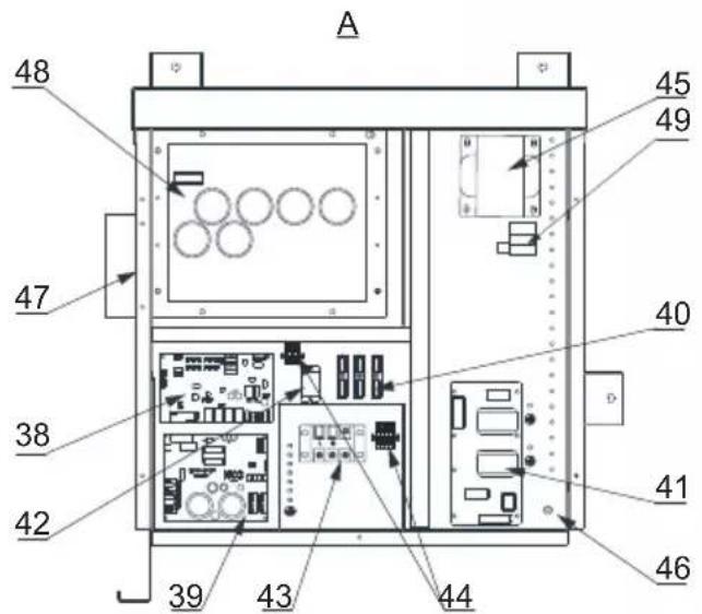
HP5171DT3 / HP5211DT3 / HP5251DT3 / HP5301DT3
| Rep | Designação Ref | HP5171DT3 | HP5211DT3 | HP5251DT3 | HP5301DT3 | |
| 1 | Motor do ventilador | HWX20000330381 | √ | √ | n/a | |
| HWX20000330402 n/a | n/a | n/a | √ | |||
| 2 | Tampa de proteção do motor HWX20000220320 | √ | √ | √ | ||
| 3 | Painel superior ABS | HWX80900736 | √ | n/a | n/a | |
| HWX80900737 n/a | √ | √ | n/a | |||
| HWX80900718 n/a | n/a | n/a | √ | |||
| 4 | Proteção lateral direita | HWX80704158 | √ | n/a | n/a | |
| HWX80705113 n/a | √ | √ | n/a | |||
| HWX80705110 n/a | n/a | n/a | √ | |||
| 5 | / / / / / / | |||||
| 6 | Placa de proteção | HWX32012210724 | √ | n/a | n/a | |
| HWX32002210071 n/a | √ | √ | n/a | |||
| HWX32004210137 n/a | n/a | n/a | √ | |||
| 7 | Medição da pressão 90 mm 1/2" | HWX20000140153 | √ | √ | √ | |
| 8 | Regulador electrónico | HWX20000140451 | √ | n/a | n/a | |
| HWX20000140449 n/a | √ | n/a | n/a | |||
| HWX20000140442 n/a | n/a | √ | n/a | |||
| HWX20000140401 n/a | n/a | n/a | √ | |||
| 9 | Filtro ∅12.9-∅12.9 (∅28) | HWX20000140027 | √ | √ | √ | |
| 10 | Medição da pressão 95 mm 7/16" | HWX20000140512 | √ | √ | √ | |
| 11 | Medição da pressão 40 mm 1/2" | HWX20000140150 | √ | √ | √ | |
| 12 | Válvula de 4 vias | HWX20041437 | √ | n/a | n/a | |
| HWX20011491 n/a | √ | √ | √ | |||
| 13 | Sensor de pressão | HWX20000360274 | √ | √ | √ | |
| 14 | Sonda temperatura Evapo/ar/água 5k-800 mm | HWX20003202 | √ | √ | √ | |
| 15 | Sonda de descarga compressor 50k-600 mm HWX20000320145 | √ | √ | √ | √ | |
| 16 | Detector de débito de água | HWX83000069 | √ | √ | √ | |
| 17 | / / / / / / | |||||
| 18 | Painel dianteiro | HWX80900738 | √ | n/a | n/a | |
| HWX80900739 n/a | √ | √ | n/a | |||
| HWX80900710 n/a | n/a | n/a | √ | |||
| 19 | Ecrã táctil colorido | HWX95005310612 | √ | √ | √ | |
| 20 | Alçapão de acesso eléctrico | HWX20000220247 | √ | √ | √ | |
| 21 | Painel da caixa elétrica | HWX80702647 | √ | n/a | n/a | |
| HWX80702644 n/a | √ | √ | n/a | |||
| HWX80702645 n/a | n/a | n/a | x | |||
| 22 | Pressóstato de alta pressão NC 3.2 MPa/4.4 MPa | HWX20000360187 | √ | √ | √ | |
| 23 | Pressóstato de baixa pressão NO 0.15 MPa/0.05 MPa | HWX20000360054 | √ | √ | √ | |
| 24 | / / / / / / | |||||
| 25 | Condensador Titânio/PVC | HWX32009120085 | √ | n/a | n/a | |
| HWX32002120023 n/a | √ | n/a | n/a | |||
| HWX32016120012 n/a | n/a | n/a | √ | |||
| HWX32016120011 | n/a | n/a | √ | |||
| 26 | / / / / / / | |||||
| 27 | Compressor | HWX80100046 | √ | n/a | n/a | |
| HWX80100069 n/a | √ | √ | n/a | |||
| HWX30101000006 n/a | n/a | n/a | √ | |||
| 28 | Proteção lateral esquerda | HWX32012210729 | √ | n/a | n/a | |
| HWX80705114 n/a | √ | √ | n/a | |||
| HWX80705111 | n/a | n/a | √ |

HP5171DT3 / HP5211DT3 / HP5251DT3 / HP5301DT3
| Rep | Designação Ref | HP5171DT3 | HP5211DT3 | HP5251DT3 | HP5301DT3 | |
| 29 | / / / / / | |||||
| 30 | Conector quadrado roscado 50 mm HWX20031379 | √ | √ | √ | ||
| 31 | Curva PVC ∅ 50 mm HWX20011359 | √ | √ | √ | ||
| 32 | Suporte vertical direito/esquerdo | HWX32000210086 | √ | n/a n/a n/a | ||
| HWX80702346 n/a | √ | √ | n/a | |||
| HWX80702656 n/a | n/a n/a | √ | ||||
| 33 | Evaporador de alheta | HWX32012120155 | √ | n/a n/a n/a | ||
| HWX80600429 n/a | √ | n/a n/a | ||||
| HWX32003120028 | n/a n/a | √ | n/a | |||
| HWX32004120013 | n/a n/a n/a | √ | ||||
| 34 | Proteção traseira | HWX32012210730 | √ | n/a n/a n/a | ||
| HWX80705115 | n/a | √ | √ | n/a | ||
| HWX80705112 | n/a n/a n/a | √ | ||||
| 35 | / / / / / | |||||
| 36 | Hélice ventilador ∅ 522 mm | HWX20000270062 | √ | n/a n/a n/a | ||
| Hélice ventilador ∅ 560 mm | HWX35072195 n/a | √ | √ | n/a | ||
| Hélice ventilador ∅ 600 mm | HWX20000270057 | n/a | n/a | n/a | √ | |
| 37 | Grelha de proteção do ventilador | HWX32012210732 | √ | n/a n/a n/a | ||
| HWX32003210142 | n/a | √ | √ | n/a | ||
| HWX80700160 n/a | n/a n/a | √ | ||||
| 38 | Placa eletrónica mãe | HWX72200033171D | √ | n/a n/a n/a | ||
| HWX72200033211D | n/a | √ | n/a n/a | |||
| HWX72200033251D | n/a n/a | √ | n/a | |||
| HWX72200033301D | n/a n/a n/a | √ | ||||
| 39 | Mapa Ventilador Inverter | HWX82300485 | √ | √ | √ | |
| 40 | Terminal de 4 ligações | HWX20003909 | √ | √ | √ | |
| 41 | Placa filtro | HWX3020100007 | √ | √ | √ | |
| 42 | Relés K2 | HWX20000360297 | √ | √ | √ | |
| 43 | Terminal L-N-GND | HWX20000390223 | √ | √ | √ | |
| 44 | Terminal 4 pinos | HWX20000390046 | √ | √ | √ | |
| 45 | Bobina reatância | HWX82500009 | √ | n/a n/a n/a | ||
| HWX20000370030 | n/a | √ | √ | √ | ||
| 46 | / / / / / | |||||
| 47 | / / / / / | |||||
| 48 | Mapa Ventilador compressor | HWX82300149 | √ | n/a n/a n/a | ||
| HWX82300019 n/a | √ | √ | √ | |||
| 49 | Resistência PTC 100 Ω | HWX20000320113 | n/a | √ | √ | √ |
| 50 | / / / / / | |||||
| 51 | / / / / / | |||||
| 52 | Contator de potência | HWX200003600619 | n/a | √ | √ | √ |
| 53 | Garrafa de líquido | HWX20000140579 | n/a | n/a | √ | √ |

HP5211ET3 / HP5251ET3 / HP5301ET3
| Rep | Designação Ref HP5211ET3 HP5251ET3 HP5301 | ET3 | |||
| 1 M | Motor do ventilador | HWX20000330381 | √ | √ | n/a |
| HWX20000330402 n/a | n/a | √ | |||
| 2 T | Tampa de proteção do motor HWX20000220320 | √ √ | √ | ||
| 3 P | Painel superior ABS | HWX80900737 | √ | √ | n/a |
| HWX80900718 n/a | n/a | √ | |||
| 4 P | Proteção lateral direita | HWX80705113 | √ | √ | n/a |
| HWX80705110 n/a | n/a | √ | |||
| 5 / | / / / / | ||||
| 6 P | Placa de proteção | HWX32002210071 | √ | √ | n/a |
| HWX32004210137 n/a | n/a | √ | |||
| 7 M | Medição da pressão 90 mm 1/2» | HWX20000140153 | √ √ | √ | |
| 8 R | Regulador electrónico | HWX20000140449 | √ | n/a | n/a |
| HWX20000140442 n/a | √ | n/a | |||
| HWX20000140401 n/a | n/a | √ | |||
| 9 F | Filtro ∅12.9-∅12.9 (∅28) | HWX20000140027 | √ √ | √ | |
| 10 | Medição da pressão 95 mm 7/16" | HWX20000140512 | √ √ | √ | |
| 11 | Medição da pressão 40 mm 1/2" | HWX20000140150 | √ √ | √ | |
| 12 | Válvula de 4 vias | HWX20011491 | √ √ | √ | |
| 13 | Sensor de pressão | HWX20000360274 | √ √ | √ | |
| 14 | Sonda temperatura Evapo/ar/água 5k-800 mm | HWX20003202 | √ √ | √ | |
| 15 | Sonda de descarga compressor 50 k-600 mm | HWX20000320145 | √ √ | √ | |
| 16 | Detector de débito de água | HWX83000069 | √ √ | √ | |
| 17 | /// / / | ||||
| 18 | Painel dianteiro | HWX80900739 | √ | √ | n/a |
| HWX80900710 n/a | n/a | √ | |||
| 19 | Ecrã táctil colorido | HWX95005310612 | √ √ | √ | |
| 20 | Alçapão de acesso eléctrico | HWX20000220247 | √ √ | √ | |
| 21 | Painel da caixa elétrica | HWX80702644 | √ | √ | n/a |
| HWX80702645 n/a | n/a | √ | |||
| 22 | Pressóstato de alta pressão NC 3.2 MPa/4.4 MPa | HWX20000360187 | √ √ | √ | |
| 23 | Pressóstato de baixa pressão NO 0.15 MPa/0.05 MPa | HWX20000360054 | √ √ | √ | |
| 24 | /// / / | ||||
| 25 | Condensador Titânio/PVC | HWX32002120023 | √ | n/a | n/a |
| HWX32016120012 n/a | √ | n/a | |||
| HWX32016120011 | n/a | n/a | √ | ||
| 26 | /// / / | ||||
| 27 | Compressor | HWX80100069 | √ | √ | n/a |
| HWX30101000006 n/a | n/a | √ | |||
| 28 | Proteção lateral esquerda | HWX80705114 | √ | √ | n/a |
| HWX80705111 | n/a | n/a | √ | ||
| 29 | /// / / | ||||
| 30 | Conector quadrado roscado 50 mm | HWX20031379 | √ √ | √ | |
| 31 | Curva PVC ∅ 50 mm | HWX20011359 | √ √ | √ | |
| 32 | Suporte vertical direito/esquerdo | HWX80702346 | √ | √ | n/a |
| HWX80702656 n/a | n/a | ||||
| 33 | Evaporador de alheta | HWX80600429 | √ | n/a | n/a |
| HWX32003120028 n/a | √ | n/a | |||
| HWX32004120013 n/a | n/a | √ | |||
| 34 | Proteção traseira | HWX80705115 | √ | √ | n/a |
| HWX80705112 n/a | n/a | √ | |||
| 35 | /// / / |

natural_image
Exterior view of a modern industrial water heater (no visible text or symbols)
HP5171DT3 HP5211DT3 HP5251DT3 HP5301DT3 HP5211ET3 HP5251ET3 HP5301ET3
Allgemeine Stromversorgung 400V 3N\~50Hz
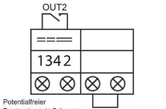
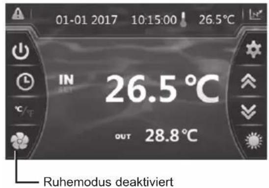
natural_image
Technical line drawing of a mechanical device with internal components and an upward arrow indicator (no text or symbols)natural_image
Technical line drawing of a mechanical device with internal components and an upward arrow indicator (no text or symbols)
HP5171DT3 / HP5211DT3 / HP5251DT3 / HP5301DT3
| Nr | Beschreibung Ref. | HP5171DT3 | HP5211DT3 | HP5251DT3 | HP5301DT3 | |
| 1 | Motor Ventilator DC | HWX20000330381 | √ | √ | √ | |
| HWX20000330402 n/a | n/a | n/a | ||||
| 2 | Motor-Schutzhaube HWX20000220320 | √ | √ | √ | ||
| 3 | Obere Wand ABS | HWX80900736 | √ | n/a | n/a | |
| HWX80900737 n/a | √ | √ | ||||
| HWX80900718 n/a | n/a | n/a | ||||
| 4 | Seitenabdeckung rechts | HWX80704158 | √ | n/a | n/a | |
| HWX80705113 n/a | √ | √ | ||||
| HWX80705110 n/a | n/a | n/a | ||||
| 5 | / / / / | / / | ||||
| 6 | Schutzplatte | HWX32012210724 | √ | n/a | n/a | |
| HWX32002210071 n/a | √ | √ | ||||
| HWX32004210137 n/a | n/a | n/a | ||||
| 7 | Druckanschluss 90 mm - 1/2" | HWX20000140153 | √ | √ | √ | |
| 8 | Elektronischer Sensor | HWX20000140451 | √ | n/a | n/a | |
| HWX20000140449 n/a | √ | n/a | ||||
| HWX20000140442 n/a | n/a | √ | ||||
| HWX20000140401 n/a | n/a | n/a | ||||
| 9 | Filter ∅12.9-∅12.9 (∅28) | HWX20000140027 | √ | √ | √ | |
| 10 | Druckanschluss 95 mm - 7/16" | HWX20000140512 | √ | √ | √ | |
| 11 | Druckanschluss 40 mm - 1/2" | HWX20000140150 | √ | √ | √ | |
| 12 | 4-Wege-Ventil | HWX20041437 | √ | n/a | n/a | |
| HWX20011491 n/a | √ | √ | ||||
| 13 | Drucksensor | HWX20000360274 | √ | √ | √ | |
| 14 | Temperatursensor Evapo/Luft/Wasser 5k-800 mm | HWX20003202 | √ | √ | √ | |
| 15 | Abgabekompressorsensor 50k-600 mm HWX20000320145 | HWX83000069 | √ | √ | √ | |
| 16 | Sensor des Wasserdurchsatzes | HWX83000069 | √ | √ | √ | |
| 17 | / / / / | / / | ||||
| 18 | Schild Vorne | HWX80900738 | √ | n/a | n/a | |
| HWX80900739 n/a | √ | √ | ||||
| HWX80900710 n/a | n/a | n/a | ||||
| 19 | Farb-Touchscreen | HWX95005310612 | √ | √ | √ | |
| 20 | Elektrische Zugangsklappe Schwarz | HWX20000220247 | √ | √ | √ | |
| 21 | Schaltkasten | HWX80702647 | √ | n/a | n/a | |
| HWX80702644 n/a | √ | √ | ||||
| HWX80702645 n/a | n/a | n/a | x | |||
| 22 | Druckregler Hochdruck NC 3.2 MPa/4.4 MPa HWX20000360187 | √ | √ | √ | ||
| 23 | Druckregler Niedrigdruck NO 0.15 MPa/0.05 MPa | HWX20000360054 | √ | √ | √ | |
| 24 | / / / / | / / | ||||
| 25 | Titan/PVC--Kondensator | HWX32009120085 | √ | n/a | n/a | |
| HWX32002120023 n/a | √ | n/a | ||||
| HWX32016120012 n/a | n/a | √ | ||||
| HWX32016120011 | n/a | n/a | ||||
| 26 | / / / / | / / | ||||
| 27 | Kompressor | HWX80100046 | √ | n/a | n/a | |
| HWX80100069 n/a | √ | √ | ||||
| HWX30101000006 n/a | n/a | n/a | ||||
| 28 | Seitenabdeckung links | HWX32012210729 | √ | n/a | n/a | |
| HWX80705114 n/a | √ | √ | ||||
| HWX80705111 | n/a | n/a | ||||


HP5211ET3 / HP5251ET3 / HP5301ET3
| Nr | Beschreibung Ref. HP5211ET3 HP5251ET3 HP5301ET3 | ||||
| 1 M | Motor Ventilator DC | HWX20000330381 | √ | √ | n/a |
| HWX20000330402 n/a | n/a | √ | |||
| 2 M | Motor-Schutzhaube HWX20000220320 | √ √ | √ | ||
| 3 C | Obere Platte | HWX80900737 | √ | √ | n/a |
| HWX80900718 n/a n/a | √ | ||||
| 4 | Seitenabdeckung rechts | HWX80705113 | √ | √ | n/a |
| HWX80705110 n/a n/a | √ | ||||
| 5 / | / / / / | ||||
| 6 | Schutzplatte | HWX32002210071 | √ | √ | n/a |
| HWX32004210137 n/a | n/a | √ | |||
| 7 | Druckanschluss 90 mm - 1/2" | HWX20000140153 | √ √ | √ | |
| 8 | Elektronischer Sensor | HWX20000140449 | √ | n/a | n/a |
| HWX20000140442 n/a | √ | n/a | |||
| HWX20000140401 n/a | n/a | √ | |||
| 9 | Filter ∅12.9-∅12.9 (∅28) | HWX20000140027 | √ √ | √ | |
| 10 | Druckanschluss 95 mm - 7/16" | HWX20000140512 | √ √ | √ | |
| 11 | Druckanschluss 40 mm - 1/2" | HWX20000140150 | √ √ | √ | |
| 12 | 4-Wege-Ventil | HWX20011491 | √ √ | √ | |
| 13 | Drucksensor | HWX20000360274 | √ √ | √ | |
| 14 | Temperatursensor Evapo/Luft/Wasser 5k-800 mm | HWX20003202 | √ √ | √ | |
| 15 | Abgabekompressorsensor 50k-600 mm | HWX20000320145 | √ √ | √ | |
| 16 | Sensor des Wasserdurchsatzes | HWX83000069 | √ √ | √ | |
| HWX83000012 n/a n/a | √ | ||||
| 17 | / / / / / | ||||
| 18 | Schild Vorne | HWX80900739 | √ | √ | n/a |
| HWX80900710 n/a n/a | √ | ||||
| 19 | Farb-Touchscreen | HWX95005310612 | √ √ | √ | |
| 20 | Elektrische Zugangsklappe Schwarz | HWX20000220247 | √ √ | √ | |
| 21 | Schaltkasten | HWX80702644 | √ | √ | n/a |
| HWX80702645 n/a n/a | √ | ||||
| 22 | Druckregler Hochdruck NC 3.2 MPa/4.4 MPa | HWX20000360187 | √ √ | √ | |
| 23 | Druckregler Niedrigdruck NO 0.15 MPa/0.05 MPa | HWX20000360054 | √ √ | √ | |
| 24 | / / / / / | ||||
| 25 | Titan/PVC--Kondensator | HWX32002120023 | √ | n/a | n/a |
| HWX32016120012 n/a | √ | n/a | |||
| HWX32016120011 | n/a n/a | √ | |||
| 26 | / / / / / | ||||
| 27 | Kompressor | HWX80100069 | √ | √ | n/a |
| HWX30101000006 n/a | n/a | √ | |||
| 28 | Seitenabdeckung links | HWX80705114 | √ | √ | n/a |
| HWX80705111 | n/a n/a | √ | |||
| 29 | / / / / / | ||||
| 30 | Rechteckiger Steckverbinder mit Gewinde 50 mm | HWX20031379 | √ √ | √ | |
| 31 | Kniestück PVC ∅ 50 mm | HWX20011359 | √ √ | √ | |
| 32 | Vertikale Stütze rechts/links | HWX80702346 | √ | √ | n/a |
| HWX80702656 n/a n/a | √ | ||||
| 33 | Flügelevaporator | HWX80600429 | √ | n/a | n/a |
| HWX32003120028 n/a | √ | n/a | |||
| HWX32004120013 n/a | n/a | √ | |||
| 34 | Schutzabdeckung hinten | HWX80705115 | √ | √ | n/a |
| HWX80705112 n/a n/a | √ | ||||
| 35 | / / / / / | ||||

natural_image
Exterior view of a modern industrial water heater (no visible text or symbols)
HP5171DT3 HP5211DT3 HP5251DT3 HP5301DT3 HP5211ET3 HP5251ET3 HP5301ET3
natural_image
Technical line drawing of a mechanical or electrical component with grid pattern and mounting brackets (no text or symbols)
natural_image
Technical line drawing of a mechanical component with labeled dimension A (no text or symbols beyond label)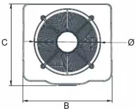
Unit : mm
| Merkteken\Modell | HP5171DT3 HP | 5211DT3 HP5 | 251DT3 HP530 | 1DT3 HP5211ET | 3 HP5251ET3 | HP5301ET3 | |
| A | 867,5 965 | 965 1024 96 | 5 965 1024 | ||||
| B | 730 777 | 777 920 777 | 777 920 | ||||
| C | 780 797 | 797 846 797 | 797 846 | ||||
| ∅ | 610 650 | 650 680 650 | 650 680 | ||||
| D | 120 120 | 120 150 120 | 120 150 | ||||
| E | 204 204 | 204 242 204 | 204 242 | ||||
| F | 87 85 85 | 86 85 85 86 |
3. INSTALLATIE EN AANSLUITING
3.1 Basisschema
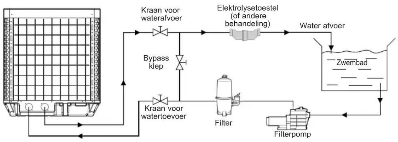
flowchart
graph TD
    A["Water tank"] --> B["Kraan voor waterafvoer"]
    B --> C["Bypass klep"]
    C --> D["Filter"]
    D --> E["Water afvoer"]
    E --> F["Wet"]
    F --> G["Zwembad"]
    G --> H["Filterpomp"]
    H --> I["Water afvoer"]
    I --> J["Elektrolysetoestel (of andere behandeling)"]
    J --> K["Kraan voor waterefoer"]
    K --> B
Algemene voeding 400V 3N\~ 50Hz
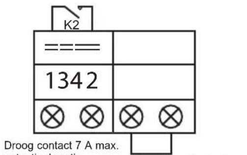
In Modus "OFF" of "ON"
Handmatige deactivering
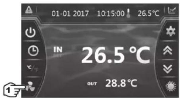


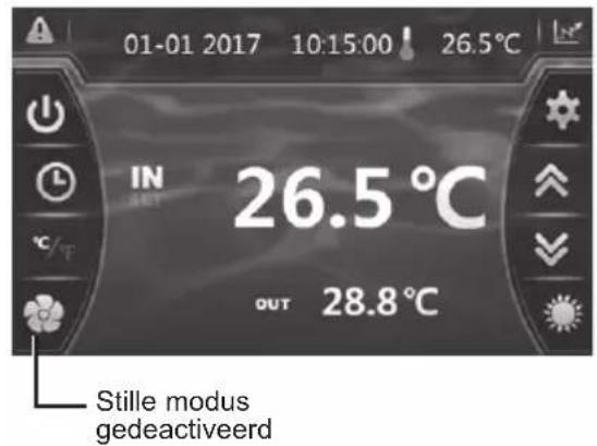
natural_image
Technical line drawing of a mechanical device with internal components and an upward arrow indicator (no text or symbols)natural_image
Technical line drawing of a mechanical device with internal components and an upward arrow indicator (no text or symbols)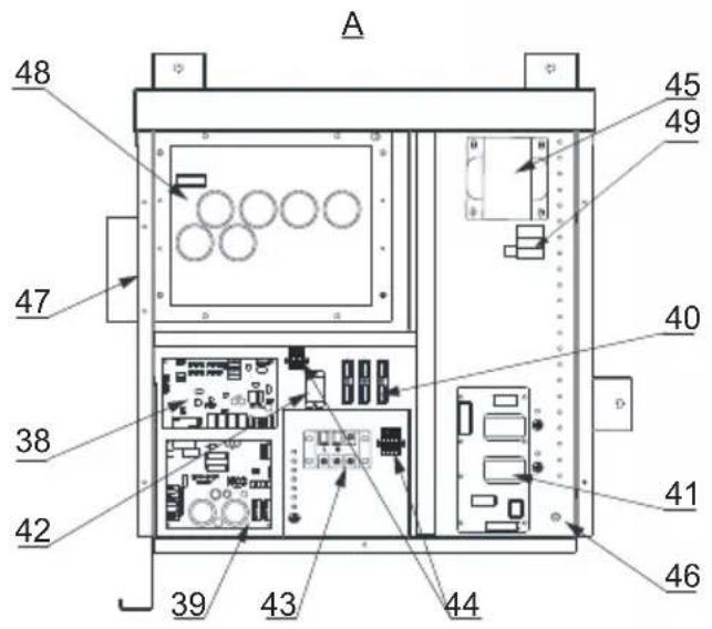
HP5171DT3 / HP5211DT3 / HP5251DT3 / HP5301DT3

HP5171DT3 / HP5211DT3 / HP5251DT3 / HP5301DT3

HP5211ET3 / HP5251ET3 / HP5301ET3
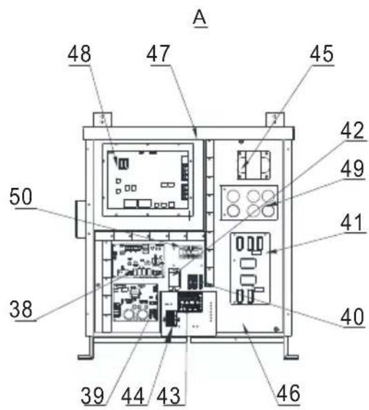
natural_image
Exterior view of a modern industrial water heater (no visible text or symbols)
HP5171DT3 HP5211DT3 HP5251DT3 HP5301DT3 HP5211ET3 HP5251ET3 HP5301ET3
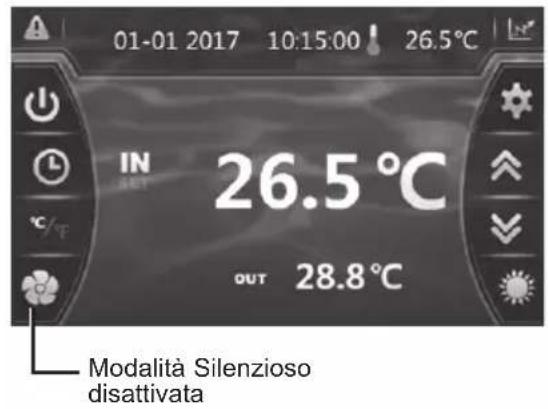
LEGENDA
PS : SENSORE DI PRESSIONE
AT : SONDA TEMPERATURA ARIA
OT : SONDA TEMPERATURA ACQUA IN USCITA
natural_image
Technical line drawing of a mechanical device with internal components and an upward arrow indicator (no text or symbols)6. APPENDICI (segue)
natural_image
Technical line drawing of a mechanical device with internal components and an upward arrow indicator (no text or symbols)6. APPENDICI (segue)
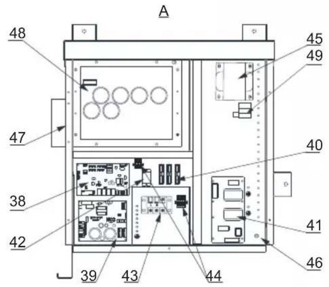
HP5171DT3 / HP5211DT3 / HP5251DT3 / HP5301DT3
| Num. | Designazione Rif. | HP5171DT3 | HP5211DT3 | HP5251DT3 | HP5301DT3 | |
| 1 | Motore ventola DC | HWX20000330381 | √ | √ | √ | |
| HWX20000330402 n/a | n/a | n/a | ||||
| 2 | Coperchio di protezione del motore HWX200002203 | 20 | √ | √ | √ | |
| 3 | Pannello superiore ABS | HWX80900736 | √ | n/a | n/a | |
| HWX80900737 n/a | √ | √ | n/a | |||
| HWX80900718 n/a | n/a | n/a | √ | |||
| 4 | Protezione laterale destra | HWX80704158 | √ | n/a | n/a | |
| HWX80705113 n/a | √ | √ | n/a | |||
| HWX80705110 n/a | n/a | n/a | √ | |||
| 5 | /////// | |||||
| 6 | Piastra protettiva | HWX32012210724 | √ | n/a | n/a | |
| HWX32002210071 n/a | √ | √ | n/a | |||
| HWX32004210137 n/a | n/a | n/a | √ | |||
| 7 | Rilevamento Pressione 90 mm - 1/2" | HWX20000140153 | √ | √ | √ | |
| 8 | Riduttore di pressione elettronico | HWX20000140451 | √ | n/a | n/a | |
| HWX20000140449 n/a | √ | n/a | n/a | |||
| HWX20000140442 n/a | n/a | √ | n/a | |||
| HWX20000140401 n/a | n/a | n/a | √ | |||
| 9 | Filtro ∅12.9-∅12.9 (∅28) | HWX20000140027 | √ | √ | √ | |
| 10 | Rilevamento pressione 95 mm - 7/16" | HWX20000140512 | √ | √ | √ | |
| 11 | Rilevamento pressione 40 mm - 1/2" | HWX20000140150 | √ | √ | √ | |
| 12 | Valvola 4 vie | HWX20041437 | √ | n/a | n/a | |
| HWX20011491 n/a | √ | √ | √ | |||
| 13 | Sensore di Pressione | HWX20000360274 | √ | √ | √ | |
| 14 | Sonda temperatura evapo/aria/acqua 5k-800 mm | HWX20003202 | √ | √ | √ | |
| 15 | Sonda scarico compressore 50k-600 mm | HWX20000320145 | √ | √ | √ | |
| 16 | Rilevatore portata acqua | HWX83000069 | √ | √ | √ | |
| 17 | ///// | |||||
| 18 | Pannello anteriore | HWX80900738 | √ | n/a | n/a | |
| HWX80900739 n/a | √ | √ | n/a | |||
| HWX80900710 n/a | n/a | n/a | √ | |||
| 19 | Touch screen a colori | HWX95005310612 | √ | √ | √ | |
| 20 | Portello d'accesso scatola elettrica | HWX20000220247 | √ | √ | √ | |
| 21 | Quadro quadro elettrico | HWX80702647 | √ | n/a | n/a | |
| HWX80702644 n/a | √ | √ | n/a | |||
| HWX80702645 n/a | n/a | n/a | x | |||
| 22 | Pressostato Alta pressione NC 3.2 MPa/4.4 MPa | HWX20000360187 | √ | √ | √ | |
| 23 | Pressostato Bassa pressione NO 0.15 MPa/0.05 MPa | HWX20000360054 | √ | √ | √ | |
| 24 | ///// | |||||
| 25 | Condensatore Titanio/PVC | HWX32009120085 | √ | n/a | n/a | |
| HWX32002120023 n/a | √ | n/a | n/a | |||
| HWX32016120012 n/a | n/a | n/a | √ | |||
| HWX32016120011 | n/a | n/a | √ | |||
| 26 | ///// | |||||
| 27 | Compressore | HWX80100046 | √ | n/a | n/a | |
| HWX80100069 n/a | √ | √ | n/a | |||
| HWX30101000006 n/a | n/a | n/a | √ | |||
| 28 | Protezione laterale sinistra | HWX32012210729 | √ | n/a | n/a | |
| HWX80705114 n/a | √ | √ | n/a | |||
| HWX80705111 | n/a | n/a | √ |
6. APPENDICI (segue)
HP5171DT3 / HP5211DT3 / HP5251DT3 / HP5301DT3
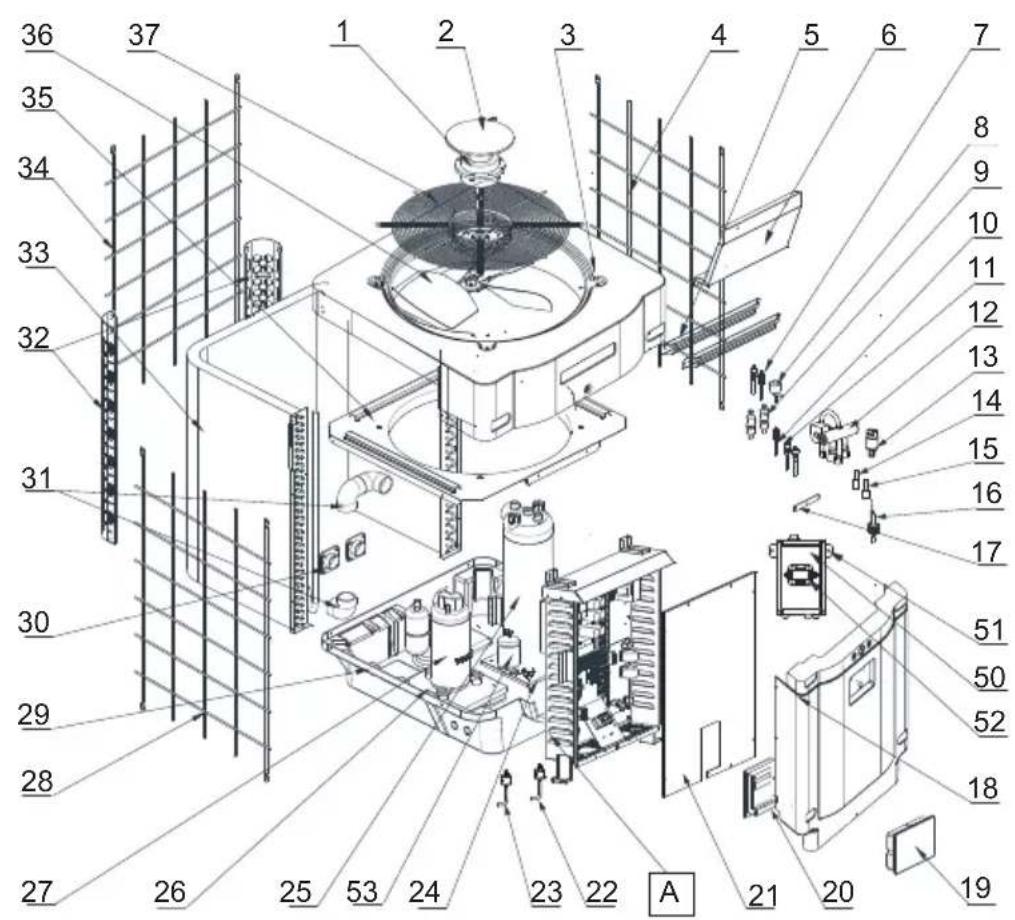

HP5171DT3 / HP5211DT3 / HP5251DT3 / HP5301DT3
| Num. | Designazione Rif. | HP5171DT3 | HP5211DT3 | HP5251DT3 | HP5301DT3 | |
| 29 | / / / / / | |||||
| 30 | Connettore quadrato filettato 50 mm HWX20031379 | √ | √ | √ | ||
| 31 | Gomito di PVC ∅ 50 mm HWX20011359 | √ | √ | √ | ||
| 32 | Supporto verticale destro/sinistro | HWX32000210086 | √ | n/a n/a n/a | ||
| HWX80702346 n/a | √ | √ | n/a | |||
| HWX80702656 n/a | n/a n/a | √ | ||||
| 33 | Evaporatore a piastre | HWX32012120155 | √ | n/a n/a n/a | ||
| HWX80600429 n/a | √ | n/a n/a | ||||
| HWX32003120028 n/a n/a | √ | n/a | ||||
| HWX32004120013 n/a n/a n/a | √ | |||||
| 34 | Protection arrière | HWX32012210730 | √ | n/a n/a n/a | ||
| HWX80705115 | n/a | √ | √ | n/a | ||
| HWX80705112 | n/a n/a n/a | √ | ||||
| 35 | / / / / / | |||||
| 36 | Elica ventilatore ∅ 522 mm | HWX20000270062 | √ | n/a n/a n/a | ||
| Elica ventilatore ∅ 560 mm | HWX35072195 n/a | √ | √ | n/a | ||
| Elica ventilatore ∅ 600 mm | HWX20000270057 n/a n/a n/a | √ | ||||
| 37 | Griglia di protezione ventilatore | HWX32012210732 | √ | n/a n/a n/a | ||
| HWX32003210142 n/a | √ | √ | n/a | |||
| HWX80700160 n/a | n/a n/a | √ | ||||
| 38 | Scheda madre elettronica | HWX72200033171D | √ | n/a n/a n/a | ||
| HWX72200033211D | n/a | √ | n/a n/a | |||
| HWX72200033251D | n/a n/a | √ | n/a | |||
| HWX72200033301D | n/a n/a n/a | √ | ||||
| 39 | Scheda Inverter ventola | HWX82300485 | √ | √ | √ | |
| 40 | Morsettiera 4 connessioni | HWX20003909 | √ | √ | √ | |
| 41 | Scheda filtro | HWX3020100007 | √ | √ | √ | |
| 42 | Relè K2 | HWX20000360297 | √ | √ | √ | |
| 43 | Morsettiera L-N-GND | HWX20000390223 | √ | √ | √ | |
| 44 | Morsettiera 4 poli | HWX20000390046 | √ | √ | √ | |
| 45 | Bobina di reattanza | HWX82500009 | √ | n/a n/a n/a | ||
| HWX20000370030 n/a | √ | √ | √ | |||
| 46 | / / / / / | |||||
| 47 | / / / / / | |||||
| 48 | Scheda Inverter compressore | HWX82300149 | √ | n/a n/a n/a | ||
| HWX82300019 n/a | √ | √ | √ | |||
| 49 | Resistenza PTC 100 Ω HWX20000320113 | n/a | √ | √ | √ | |
| 50 | / / / / / | |||||
| 51 | / / / / / | |||||
| 52 | Contattore di potenza | HWX200003600619 | n/a | √ | √ | √ |
| 53 | Bombola di liquido | HWX20000140579 n/a | n/a | √ | √ | |
6. APPENDICI (segue)
HP5211ET3 / HP5251ET3 / HP5301ET3


HP5211ET3 / HP5251ET3 / HP5301ET3
| Num. | Designazione Rif. HP5211ET3 HP5251ET3 HP53 | 01ET3 | |||
| 1 | Motore ventola DC | HWX20000330381 | √ | √ | n/a |
| HWX20000330402 n/a | n/a | √ | |||
| 2 | Coperchio di protezione del motore HWX200002203 | 20 | √ √ | √ | |
| 3 | Pannello anteriore superiore | HWX80900737 | √ | √ | n/a |
| HWX80900718 n/a n/a | √ | ||||
| 4 | Protezione laterale destra | HWX80705113 | √ | √ | n/a |
| HWX80705110 n/a n/a | √ | ||||
| 5 | /// / | ||||
| 6 | Piastra protettiva | HWX32002210071 | √ | √ | n/a |
| HWX32004210137 n/a | n/a | √ | |||
| 7 | Rilevamento Pressione 90 mm - 1/2" | HWX20000140153 | √ √ | √ | |
| 8 | Riduttore di pressione elettronico | HWX20000140449 | √ | n/a | n/a |
| HWX20000140442 n/a | √ | n/a | |||
| HWX20000140401 n/a | n/a | √ | |||
| 9 | Filtro ∅12.9-∅12.9 (∅28) | HWX20000140027 | √ √ | √ | |
| 10 | Rilevamento Pressione 95 mm - 7/16" | HWX20000140512 | √ √ | √ | |
| 11 | Rilevamento Pressione 40 mm - 1/2" | HWX20000140150 | √ √ | √ | |
| 12 | Valvola 4 vie | HWX20011491 | √ √ | √ | |
| 13 | Sensore di Pressione | HWX20000360274 | √ √ | √ | |
| 14 | Sonda temperatura evapo/aria/acqua 5k-800 mm | HWX20003202 | √ √ | √ | |
| 15 | Sonde de refoulement compresseur 50k-600 mm | HWX20000320145 | √ √ | √ | |
| 16 | Rilevatore portata acqua | HWX83000069 | √ √ | √ | |
| 17 | /// / | ||||
| 18 | Pannello anteriore | HWX80900739 | √ | √ | n/a |
| HWX80900710 n/a n/a | √ | ||||
| 19 | Touch screen a colori | HWX95005310612 | √ √ | √ | |
| 20 | Portello d'accesso scatola elettrica | HWX20000220247 | √ √ | √ | |
| 21 | Quadro quadro elettrico | HWX80702644 | √ | √ | n/a |
| HWX80702645 n/a n/a | √ | ||||
| 22 | Pressostato Alta pressione NC 3.2 MPa/4.4 MPa | HWX20000360187 | √ √ | √ | |
| 23 | Pressostato Bassa pressione NO 0.15 MPa/0.05 MPa | HWX20000360054 | √ √ | √ | |
| 24 | /// / | ||||
| 25 | Condensatore Titanio/PVC | HWX32002120023 | √ | n/a | n/a |
| HWX32016120012 n/a | √ | n/a | |||
| HWX32016120011 | n/a n/a | √ | |||
| 26 | /// / | ||||
| 27 | Compressore | HWX80100069 | √ | √ | n/a |
| HWX30101000006 n/a | n/a | √ | |||
| 28 | Protezione laterale sinistra | HWX80705114 | √ | √ | n/a |
| HWX80705111 | n/a n/a | √ | |||
| 29 | /// / | ||||
| 30 | Connettore quadrato filettato 50 mm | HWX20031379 | √ √ | √ | |
| 31 | Gomito di PVC ∅ 50 mm | HWX20011359 | √ √ | √ | |
| 32 | Supporto verticale destro/sinistro | HWX80702346 | √ | √ | n/a |
| HWX80702656 n/a n/a | √ | ||||
| 33 | Evaporatore a piastre | HWX80600429 | √ | n/a | n/a |
| HWX32003120028 n/a | √ | n/a | |||
| HWX32004120013 n/a | n/a | √ | |||
| 34 | Protezione posteriore | HWX80705115 | √ | √ | n/a |
| HWX80705112 n/a n/a | √ | ||||
| 35 | /// / |
6. APPENDICI (segue)
HP5211ET3 / HP5251ET3 / HP5301ET3


6. APPENDICI (segue)
HP5211ET3 / HP5251ET3 / HP5301ET3
| Num. | Designazione Rif. HP5211ET3 HP5251ET3 HP5301ET3 | ||||
| 36 | Elica ventilatore ∅ 560 mm HWX35072195 | √ | √ | n/a | |
| Elica ventilatore ∅ 600 mm HWX20000270057 n/a | n/a | √ | |||
| 37 | Griglia di protezione ventilatore | HWX32003210142 | √ | √ | n/a |
| HWX80700160 n/a n/a | √ | ||||
| 38 | Carte électronique Mère | HWX72200033211E | √ | n/a n/a | |
| HWX72200033251E n/a | √ | n/a | |||
| HWX72200033301E n/a | n/a | √ | |||
| 39 | Scheda Inverter ventola HWX82300485 | √ √ | √ | ||
| 40 | Morsettiera 4 connessioni | HWX20003909 | √ √ | √ | |
| 41 | Scheda filtro | HWX82300074 | √ √ | √ | |
| 42 | Relè K2 | HWX20000360297 | √ √ | √ | |
| 43 | Morsettiera R-R-T-N-GND | HWX20000390180 | √ √ | √ | |
| 44 | Morsettiera 4 poli | HWX20000390046 | √ √ | √ | |
| 45 | Bobina di reattanza | HWX20000370030 | √ √ | √ | |
| 46 / | / | / | / | / | |
| 47 | / | / | / | / | / |
| 48 | Scheda Inverter compressore | HWX82300112 | √ | √ | n/a |
| HWX302010000012 | n/a n/a | √ | |||
| 49 | Scheda condensatore | HWX302010000014 | √ √ | √ | |
| 50 | Morsettiera L-N-GND reattanza | HWX20000390223 | √ √ | √ | |
| 51 | Bombola di liquido | HWX20000140579 n/a | √ | √ | |
6. APPENDICI (segue)
natural_image
Exterior view of a modern industrial water heater (no visible text or symbols)
HP5171DT3 HP5211DT3 HP5251DT3 HP5301DT3 HP5211ET3 HP5251ET3 HP5301ET3
5. VEDLIKEHOLD OG VINTERKLARGJ∅RING 25
1. GENERELLE FORHOLDSREGLER (fortsetter)
Dette produktet inneholder kjølegassen R32

Dette apparatet inneholder R32.
(1) Globalt oppvarmingspotensial
1. GENERELLE FORHOLDSREGLER (fortsetter)
Betingelser for installering
1. GENERELLE FORHOLDSREGLER (fortsetter)
2. SPESIFIKASJONER (fortsetter)
| Modeller | SUMHEAT Full Inverter | HP5211ET3 HP5 | 251ET3 HP5301ET3 | |
| Tilførselsspenning V / Ph / Hz | 380 V - 415 V ~ / 3 ph / 50 Hz | |||
| Kuldemedium Type HFC - R32 - (CH2F2) | ||||
| Sikkerhetsgruppe Type A2L | ||||
| Last kg 1,35 1,65 1,8 | ||||
| Masse i teqCO2 | teqCO2 | 0,91 1,11 1,22 | ||
| Hyppighet for lekkasjekontroll / Er ikke påkrevet, men årlig kontroll anbefales | ||||
| Oppvarmingskapasitet Min--Maks (a) kW 6,24 -- | 22,10 6,02 -- 24,50 8,12 -- 31,20 | |||
| Absorbert elektrisk effekt Min--Maks (a) | kW | 0,46 -- 3,07 | 0,41 -- 3,67 | 0,59 -- 5,08 |
| Nominell strømverdi Min--Maks (a) | A | 1,00 -- 5,10 | 0,90 -- 5,81 | 1,21 -- 8,23 |
| COP Maks--Min (a) | / | 13,70 -- 7,19 14,53 -- 6,68 13,72 -- 6,14 | ||
| Oppvarmingskapasitet Min--Maks (b) kW 4,84 -- | 16,92 4,55 -- 19,55 5,52 -- 23,05 | |||
| Absorbert elektrisk effekt Min--Maks (b) | kW | 0,68 -- 3,10 | 0,63 -- 3,68 | 0,79 -- 4,94 |
| COP Maks--Min (b) | / | 7,10 -- 5,46 | 7,18 -- 6,42 | 6,98 -- 4,66 |
| Maksimum strømverdi | A | 8,7 11,7 13,3 | ||
| Sikringsstørrelse | aM | 10 | 12 | 16 |
| Effektbryter Kurve D | D | 10 | 12 | 16 |
| Startstrøm | A | < CMS | ||
| Hydraulisk tilkopling | mm | 50 mm | ||
| Nominell vannstrøm (a) | m3/h | 9,1 10,5 12,6 | ||
| Fall i vantrykk (maks.) | kPa | 17 | 15 | 46 |
| Kompressor | / | Panasonic | Panasonic | Mitsubishi |
| Type | / | Dobbeltroterende | ||
| Antall | / | 1 | ||
| Svingningsmotstand ved 20°C | Ohm | 0,88 | 0,88 | 0,49 |
| Vifte | / | Axial | ||
| Antall | 1 | |||
| Diameter | mm | 560 560 600 | ||
| Antall rotor | / | 3 | ||
| Motor | / | DC-omformer | ||
| Antall | / | 1 | ||
| Rotasjonshastighet | Omdr/min | 500 -- 700 | 600 -- 750 | 500 -- 700 |
| Hastighet i Silent Mode | Omdr/min | 500 | 400 | 400 |
| Lydtrykknivå ved 1 m | dB(A) | 56,4 -- 61 | 55,2 -- 59,7 | 55,6 -- 59,3 |
| Lydtrykknivå ved 10 m | dB(A) | 40,9 -- 45,4 | 40,9 -- 44,2 | 36,1 -- 42,2 |
| Enhetens dimensjoner, netto (L-I-H) | mm | 797 x 777 x 965 | 846 x 920 x 1024 | |
| Vekt | kg | 101 101 123 | ||
2. SPESIFIKASJONER (fortsetter)
2.2 Driftsområde
2. SPESIFIKASJONER (fortsetter)
2.3 Dimensjoner
Modeller:
HP5171DT3 / HP5211DT3 / HP5251DT3 / HP5301DT3
HP5211ET3 / HP5251ET3 / HP5301ET3
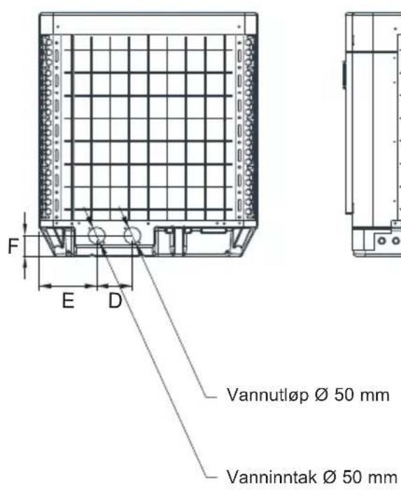
natural_image
Technical line drawing of a mechanical or electrical component with grid pattern and mounting bracket (no text or symbols)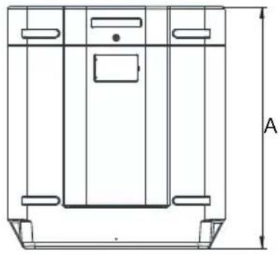
natural_image
Technical line drawing of a mechanical component with labeled dimension A (no text or symbols beyond the label)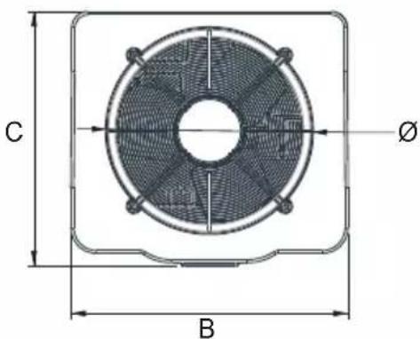
Enhet : mm
| Model Nummer | HP5171DT3 HP5211DT3 HP5251DT3 HP5301DT3 HP5211ET3 HP5251ET3 HP5301ET3 | ||||||
| A | 867,5 965 | 965 1024 965 | 965 1024 | ||||
| B | 730 777 | 777 920 777 | 777 920 | ||||
| C | 780 797 | 797 846 797 | 797 846 | ||||
| ∅ | 610 650 | 650 680 650 | 650 680 | ||||
| D | 120 120 | 120 150 120 | 120 150 | ||||
| E | 204 204 | 204 242 204 | 204 242 | ||||
| F | 87 85 85 | 86 85 85 86 | |||||
3. INSTALLERING OG TILKOBLING
3.1 Skjematisk diagram
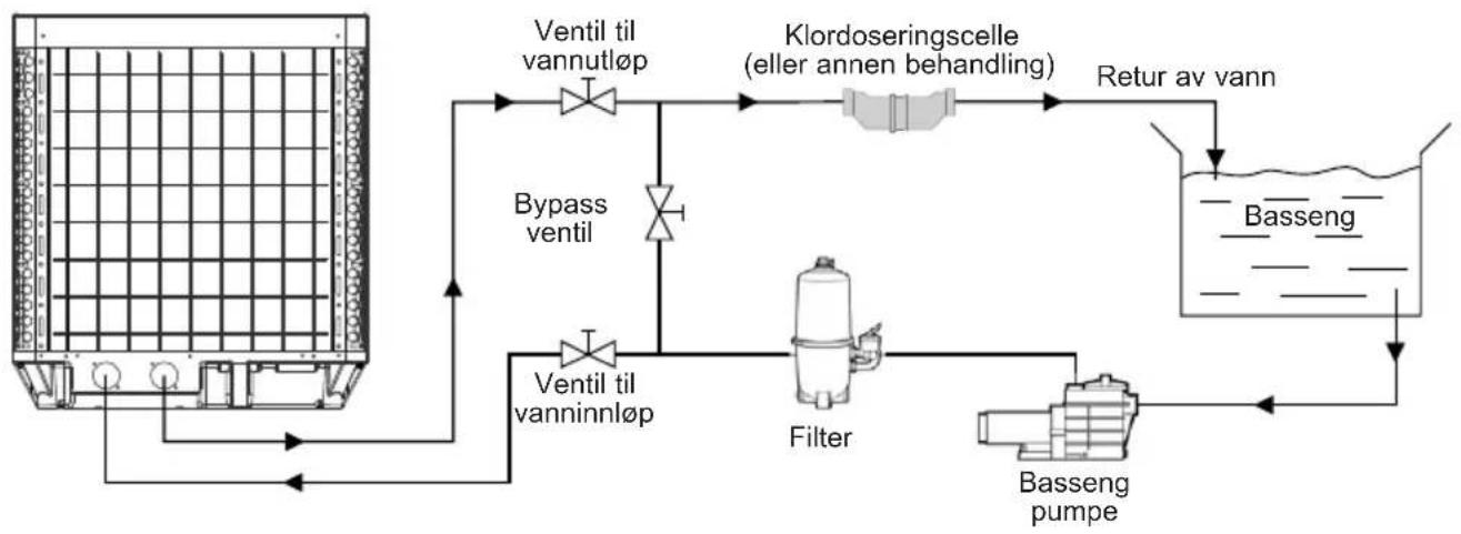
flowchart
graph TD
    A["Reactor with Ventil til vannutløp"] --> B["Ventil til vannutløp"]
    B --> C["Bypass ventil"]
    C --> D["Filter"]
    D --> E["Basseng pumpe"]
    E --> F["Return av vann"]
    F --> G["Klordoseringscelle (eller annen behandling)"]
    G --> H["Ventil til vanninnløp"]
    H --> I["Bypass ventil"]
    I --> A
3. INSTALLERING OG TILKOBLING (fortsetter)
3.2 Varmepumpe

3. INSTALLERING OG TILKOBLING (fortsetter)
3.3 Vanntilkobling
3. INSTALLERING OG TILKOBLING (fortsetter)
3.4 Elektrisk tilkobling

3. INSTALLERING OG TILKOBLING (fortsetter)
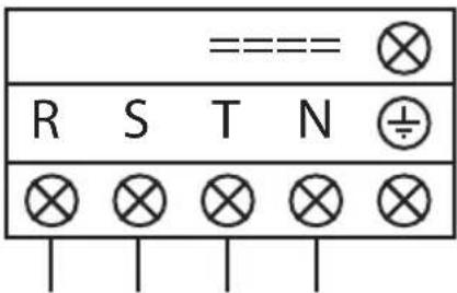
3. INSTALLERING OG TILKOBLING (fortsetter)
3. INSTALLERING OG TILKOBLING (fortsetter)
3. INSTALLERING OG TILKOBLING (fortsetter)
4. BRUKERGRENSESNITT (fortsetter)
OFF-modus
Når varmepumpen er i standby (OFF-modus) knappen ledtonet.
ON-modus
Når varmepumpen er i drift eller under innstilling (ON-modus) knappen lyser grønt.

4. BRUKERGRENSESNITT (fortsetter)
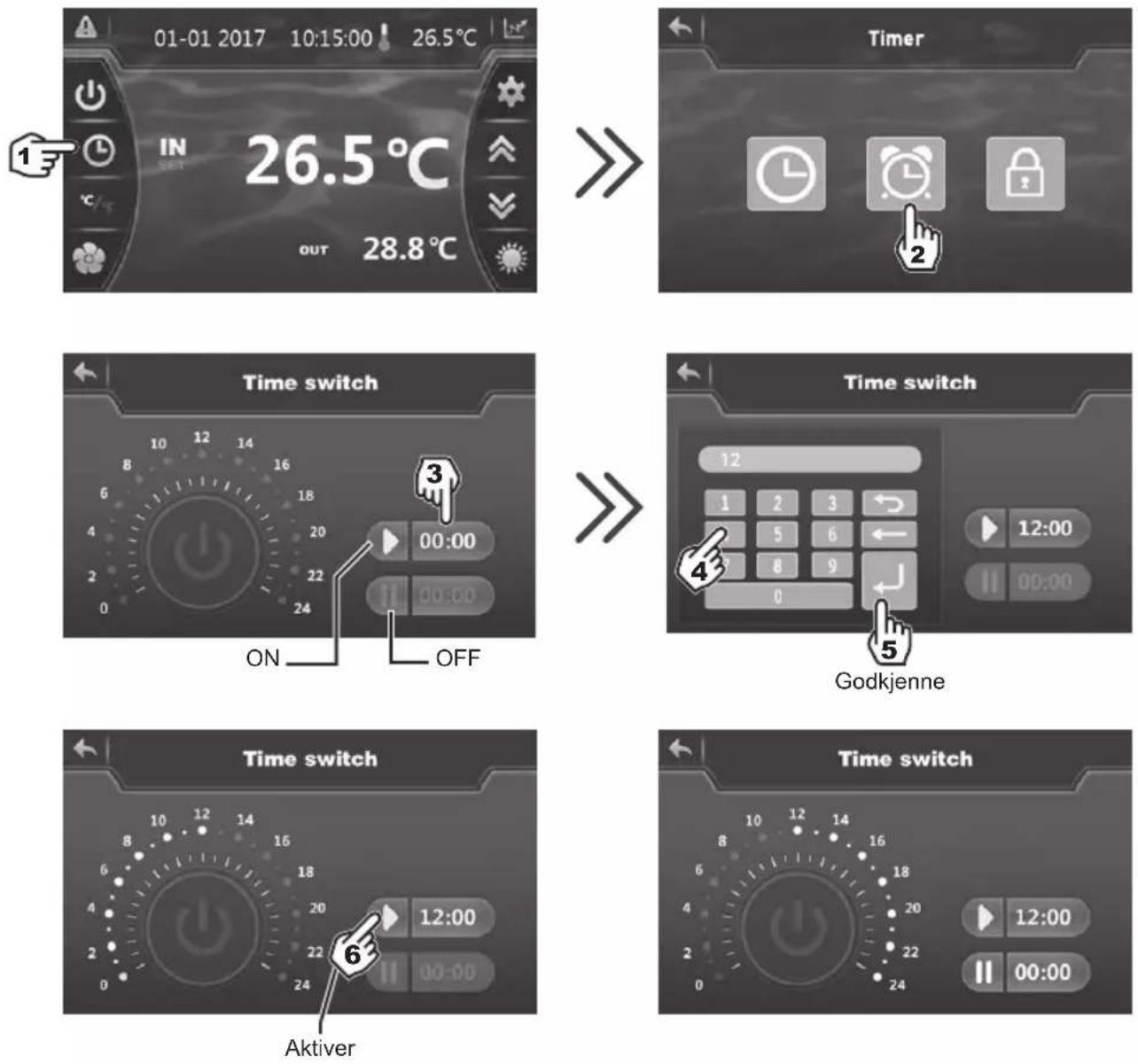

Blå marking = Aktivert
Nedtonet = Deaktivert

4. BRUKERGRENSESNITT (fortsetter)
4. BRUKERGRENSESNITT (fortsetter)
4. BRUKERGRENSESNITT (fortsetter)
4. BRUKERGRENSESNITT (fortsetter)
Manuell deaktivering


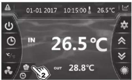
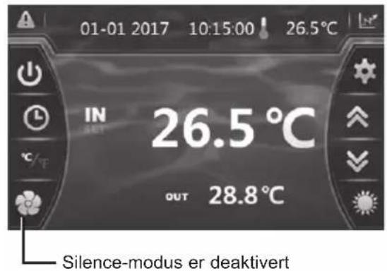
4. BRUKERGRENSESNITT (fortsetter)
6. VEDLEGG (fortsetter)
HP5211DT3 / HP5251DT3
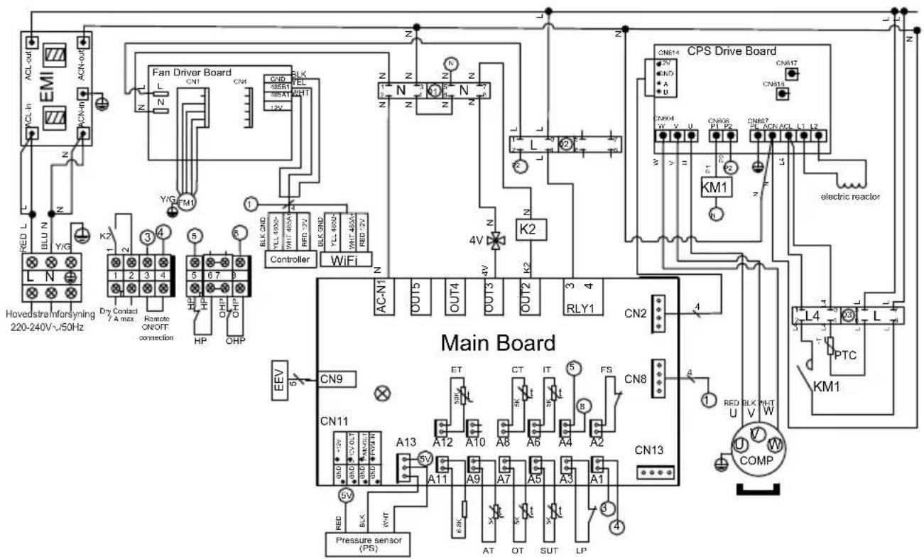
MERKNADER
PS : TRYKKSENSOR EEV : ELEKTRONISK EKSPANSJONSVENTIL
AT : SENSOR FOR LUFTTEMPERATUR
OT : TEMPERATURSENSOR TIL VANNUTL∅P
SUT : SENSOR FOR SUGETEMPERATUR
LP : LAVTRYKKSBRYTER
FS : VANNSENSOR
IT : TEMPERATURSENSOR TIL VANNINNL∅P
CT : SENSOR FOR FORDAMPET TEMPERATUR
ET : TEMPERATURSENSOR FOR UTLADNING
FM1 : VIFTEMOTOR DC
HP : H∅YTRYKKSBRYTER
OHP : VARMEBESKYTTELSE
4V : 4-VEIS VENTIL
K2 : POTENSIALFRI KONTAKT, MAKS. 7A
PTC : TERMISTOR
KM1: KOMPRESSORKONTAKTOR
COMP : KOMPRESSOR
6. VEDLEGG (fortsetter)
HP5301DT3
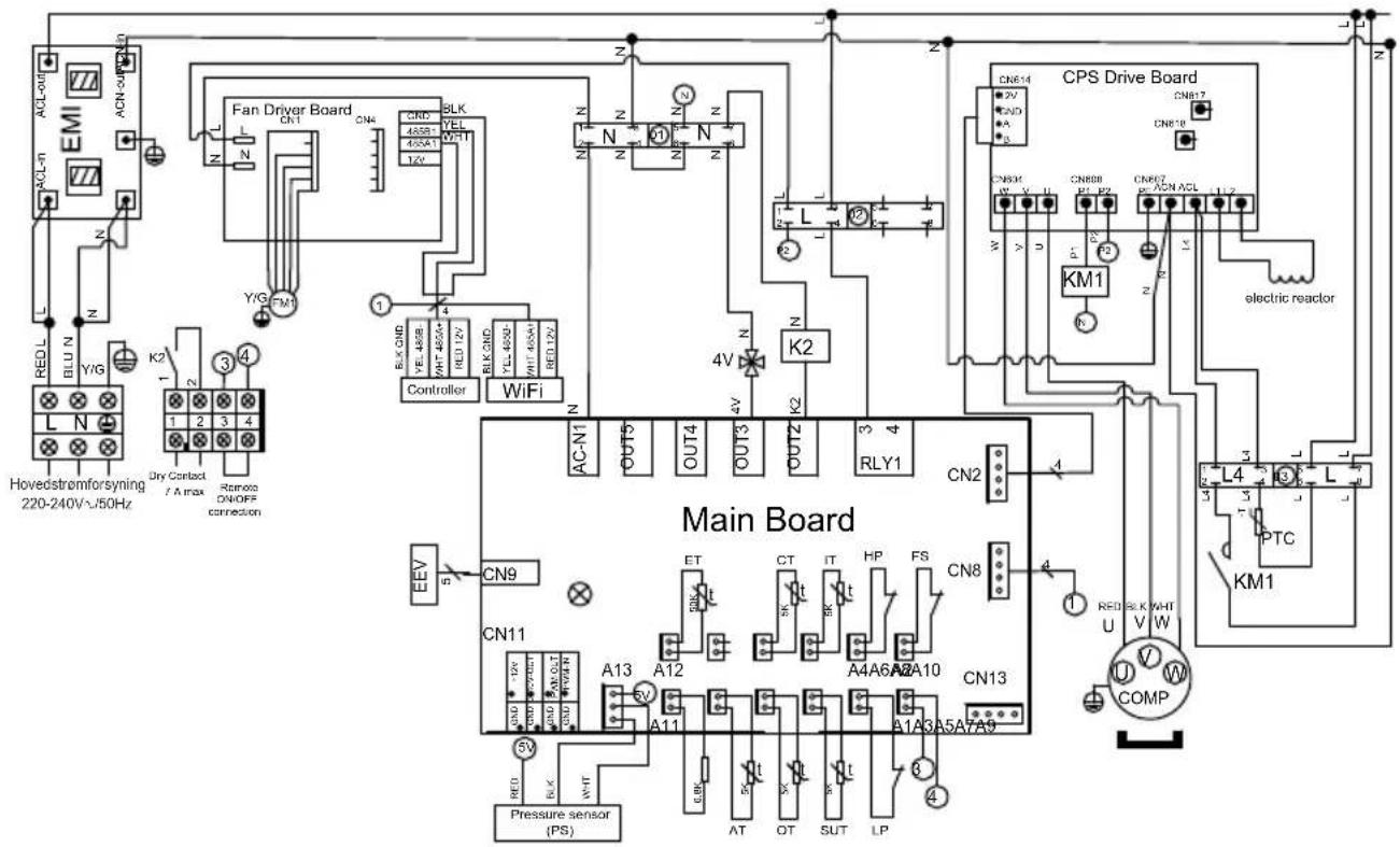
MERKNADER
PS : TRYKKSENSOR
AT : SENSOR FOR LUFTTEMPERATUR
OT : TEMPERATURSENSOR TIL VANNUTL∅P
SUT : SENSOR FOR SUGETEMPERATUR
LP : LAVTRYKKSBRYTER
FS : VANNSENSOR
HP : H∅YTRYKKSBRYTER
IT : TEMPERATURSENSOR TIL VANNINNL∅P
CT : SENSOR FOR FORDAMPET TEMPERATUR
ET : TEMPERATURSENSOR FOR UTLADNING
EEV : ELEKTRONISK EKSPANSJONSVENTIL
FM1 : VIFTEMOTOR DC
4V : 4-VEIS VENTIL
K2 : POTENSIALFRI KONTAKT, MAKS. 7 A
PTC : TERMISTOR
KM1 : KOMPRESSORKONTAKTOR
COMP: KOMPRESSOR
6. VEDLEGG (fortsetter)
HP5211ET3 / HP5251ET3
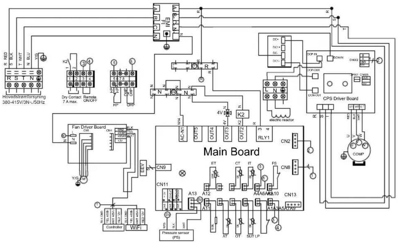
MERKNADER
PS : TRYKKSENSOR
AT : SENSOR FOR LUFTTEMPERATUR
OT : TEMPERATURSENSOR TIL VANNUTL∅P
SUT : SENSOR FOR SUGETEMPERATUR
LP : LAVTRYKKSBRYTER
FS : VANNSENSOR
IT : TEMPERATURSENSOR TIL VANNINNL∅P
CT : SENSOR FOR FORDAMPET TEMPERATUR
ET : TEMPERATURSENSOR FOR UTLADNING
EEV : ELEKTRONISK EKSPANSJONSVENTIL
FM1 : VIFTEMOTOR DC
HP : H∅YTRYKKSBRYTER
OHP : VARMEBESKYTTELSE
4V : 4-VEIS VENTIL
K2 : POTENSIALFRI KONTAKT, MAKS. 7A
COMP: KOMPRESSOR
6. VEDLEGG (fortsetter)
HP5301ET3

MERKNADER
PS : TRYKKSENSOR
AT : SENSOR FOR LUFTTEMPERATUR
OT : TEMPERATURSENSOR TIL VANNUTL∅P
SUT : SENSOR FOR SUGETEMPERATUR
LP : LAVTRYKKSBRYTER
FS : VANNSENSOR
HP : H∅YTRYKKSBRYTER
IT : TEMPERATURSENSOR TIL VANNINNL∅P
CT : SENSOR FOR FORDAMPET TEMPERATUR
ET : TEMPERATURSENSOR FOR UTLADNING
EEV : ELEKTRONISK EKSPANSJONSVENTIL
FM1 : VIFTEMOTOR DC
4V : 4-VEIS VENTIL
K2 : POTENSIALFRI KONTAKT, MAKS. 7 A
COMP : KOMPRESSOR
6. VEDLEGG (fortsetter)
6.2 Kobling med prioritet på enfaset varmepumpe

natural_image
Technical line drawing of a mechanical device with internal components and an upward arrow indicator (no text or symbols)6. VEDLEGG (fortsetter)
6.3 Kobling med prioritet på trefaset varmepumpe

natural_image
Technical line drawing of a mechanical device with internal components and an upward arrow indicator (no text or symbols)6. VEDLEGG (fortsetter)

HP5171DT3 / HP5211DT3 / HP5251DT3 / HP5301DT3
| Nr. | Betegnelse Ref. | HP5171DT3 | HP5211DT3 | HP5251DT3 | HP5301DT3 | |
| 1 | Viftemotor DC | HWX20000330381 | √ | √ | Gjelder ikke | |
| HWX20000330402 | Gjelder ikke | Gjelder ikke | Gjelder ikke | √ | ||
| 2 | Deksel for motoren HWX20000220320 | √ | √ | |||
| 3 | ∅vre deksel ABS | HWX80900736 | √ | Gjelder ikke | Gjelder ikke | Gjelder ikke |
| HWX80900737 Gjelder ikke | √ | √ | √ | Gjelder ikke | ||
| HWX80900718 Gjelder ikke Gjelder ikke | √ | √ | √ | √ | ||
| 4 | Deksel for høyre side | HWX80704158 | √ | Gjelder ikke | Gjelder ikke | Gjelder ikke |
| HWX80705113 Gjelder ikke | √ | √ | √ | Gjelder ikke | ||
| HWX80705110 Gjelder ikke Gjelder ikke | √ | √ | √ | √ | ||
| 5 | /// / / / | |||||
| 6 | Beskyttelsesplate | HWX32012210724 | √ | Gjelder ikke | Gjelder ikke | Gjelder ikke |
| HWX32002210071 Gjelder ikke | √ | √ | √ | Gjelder ikke | ||
| HWX32004210137 Gjelder ikke Gjelder ikke | √ | √ | √ | √ | ||
| 7 | Trykktilkobling 90 mm 1/2" | HWX20000140153 | √ | √ | ||
| 8 | Elektronisk ekspansjonsventil | HWX20000140451 | √ | Gjelder ikke | Gjelder ikke | Gjelder ikke |
| HWX20000140449 Gjelder ikke | √ | √ | Gjelder ikke | Gjelder ikke | ||
| HWX20000140442 Gjelder ikke Gjelder ikke | √ | √ | √ | Gjelder ikke | ||
| HWX20000140401 Gjelder ikke Gjelder ikke | √ | √ | √ | √ | ||
| 9 | Filter ∅12.9-∅12.9 (∅28) | HWX20000140027 | √ | √ | ||
| 10 | Trykktilkobling 95 mm 7/16" | HWX20000140512 | √ | √ | ||
| 11 | Trykktilkobling 40 mm 1/2" | HWX20000140150 | √ | √ | ||
| 12 | 4-veisventil | HWX20041437 | x | Gjelder ikke | Gjelder ikke | Gjelder ikke |
| HWX20011491 Gjelder ikke | √ | √ | √ | |||
| 13 | Trykksensor | HWX20000360274 | √ | √ | ||
| 14 | Fordamper/luft/vann-temperatursensor 5k 800mm | HWX20003202 | √ | √ | ||
| 15 | Kompressorutladningssonde 50k-600 mm | HWX20000320145 | √ | √ | ||
| 16 | Sensor for vannstrømning | HWX83000069 | √ | √ | ||
| 17 | /// / / / | |||||
| 18 | Fremre panel | HWX80900738 | √ | Gjelder ikke | Gjelder ikke | Gjelder ikke |
| HWX80900739 Gjelder ikke | √ | √ | √ | Gjelder ikke | ||
| HWX80900710 Gjelder ikke Gjelder ikke | √ | √ | √ | √ | ||
| 19 | Berøringsskjerm med farger | HWX95005310612 | √ | √ | ||
| 20 | Trappe elektrisk tilgang | HWX20000220247 | √ | √ | ||
| 21 | Elektrisk boks panel | HWX80702647 | √ | Gjelder ikke | Gjelder ikke | Gjelder ikke |
| HWX80702644 Gjelder ikke | √ | √ | √ | Gjelder ikke | ||
| HWX80702645 Gjelder ikke Gjelder ikke | √ | √ | √ | √ | ||
| 22 | Høytrykkspressostat NC 3.2 MPa/4.4 MPa | HWX20000360187 | √ | √ | ||
| 23 | Strømningsbegrenser NO 0.15 MPa/0.05 MPa | HWX20000360054 | √ | √ | ||
| 24 | /// / / / | |||||
| 25 | Kondensator Titanium/PVC | HWX32009120085 | √ | Gjelder ikke | Gjelder ikke | Gjelder ikke |
| HWX32002120023 Gjelder ikke | √ | √ | Gjelder ikke | Gjelder ikke | ||
| HWX32016120012 Gjelder ikke Gjelder ikke | √ | √ | √ | Gjelder ikke | ||
| HWX32016120011 Gjelder ikke | √ | √ | √ | √ | ||
| 26 | /// / / / | |||||
| 27 | Kompressor | HWX80100046 | √ | Gjelder ikke | Gjelder ikke | Gjelder ikke |
| HWX80100069 Gjelder ikke | √ | √ | √ | Gjelder ikke | ||
| HWX30101000006 Gjelder ikke Gjelder ikke | √ | √ | √ | √ | ||
| 28 | Deksel for venstre side | HWX32012210729 | √ | Gjelder ikke | Gjelder ikke | Gjelder ikke |
| HWX80705114 Gjelder ikke | √ | √ | √ | Gjelder ikke | ||
| HWX80705111 | Gjelder ikke | Gjelder ikke | Gjelder ikke | √ |
6. VEDLEGG (fortsetter)
HP5171DT3 / HP5211DT3 / HP5251DT3 / HP5301DT3

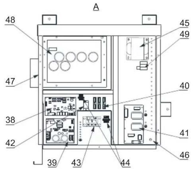
HP5171DT3 / HP5211DT3 / HP5251DT3 / HP5301DT3
| Nr. | Betegnelse Ref. | HP5171DT3 | HP5211DT3 | HP5251DT3 | HP5301DT3 | |
| 29 / | / / / / / | |||||
| 30 | Firkantet koblingsstykke med gjenge 50 mm HWX20031379 | ✓ | ✓ | ✓ | ||
| 31 | PVC bøy ∅ 50 mm HWX20011359 | ✓ | ✓ | ✓ | ||
| 32 | Vertikalt støtte høyre/venstre | HWX32000210086 | ✓ | Gjelder ikke | Gjelder ikke | Gjelder ikke |
| HWX80702346 Gjelder ikke | ✓ | ✓ | ✓ | Gjelder ikke | ||
| HWX80702656 Gjelder ikke Gjelder ikke | ✓ | ✓ | ✓ | ✓ | ||
| 33 | Vinget fordamper | HWX32012120155 | ✓ | Gjelder ikke | Gjelder ikke | Gjelder ikke |
| HWX80600429 Gjelder ikke | ✓ | ✓ | Gjelder ikke | Gjelder ikke | ||
| HWX32003120028 Gjelder ikke | ✓ | ✓ | ✓ | Gjelder ikke | ||
| HWX32004120013 Gjelder ikke | ✓ | ✓ | ✓ | ✓ | ||
| 34 | Deksel for baksiden | HWX32012210730 | ✓ | Gjelder ikke | Gjelder ikke | Gjelder ikke |
| HWX80705115 | Gjelder ikke | ✓ | ✓ | Gjelder ikke | ||
| HWX80705112 | Gjelder ikke | Gjelder ikke | Gjelder ikke | ✓ | ||
| 35 / | / / / / / | |||||
| 36 | Vifteproprell ∅ 522 mm | HWX20000270062 | ✓ | Gjelder ikke | Gjelder ikke | Gjelder ikke |
| Vifteproprell ∅ 560 mm | HWX35072195 Gjelder ikke | ✓ | ✓ | ✓ | Gjelder ikke | |
| Vifteproprell ∅ 600 mm | HWX20000270057 | Gjelder ikke | Gjelder ikke | Gjelder ikke | ✓ | |
| 37 | Beskyttelsesgitter for viften | HWX32012210732 | ✓ | Gjelder ikke | Gjelder ikke | Gjelder ikke |
| HWX32003210142 Gjelder ikke | ✓ | ✓ | ✓ | Gjelder ikke | ||
| HWX80700160 Gjelder ikke Gjelder ikke | ✓ | ✓ | ✓ | ✓ | ||
| 38 | Elektronisk hovedkort | HWX72200033171D | ✓ | Gjelder ikke | Gjelder ikke | Gjelder ikke |
| HWX72200033211D | Gjelder ikke | ✓ | Gjelder ikke | Gjelder ikke | ||
| HWX72200033251D | Gjelder ikke | Gjelder ikke | ✓ | Gjelder ikke | ||
| HWX72200033301D | Gjelder ikke | Gjelder ikke | Gjelder ikke | ✓ | ||
| 39 | Kort for Inverter vifte | HWX82300485 | ✓ | ✓ | ✓ | |
| 40 | Terminal 4 tilkoplinger | HWX20003909 | ✓ | ✓ | ✓ | |
| 41 | Filterkort | HWX3020100007 | ✓ | ✓ | ✓ | |
| 42 | Relé K2 | HWX20000360297 | ✓ | ✓ | ✓ | |
| 43 | Terminal L-N-GND | HWX20000390223 | ✓ | ✓ | ✓ | |
| 44 | 4-polet klemme | HWX20000390046 | ✓ | ✓ | ✓ | |
| 45 | Spole reaktans | HWX82500009 | ✓ | Gjelder ikke | Gjelder ikke | Gjelder ikke |
| HWX20000370030 Gjelder ikke | ✓ | ✓ | ✓ | |||
| 46 / | / / / / / | |||||
| 47 / | / / / / / | |||||
| 48 | Kort for Inverter kompressor | HWX82300149 | ✓ | Gjelder ikke | Gjelder ikke | Gjelder ikke |
| HWX82300019 Gjelder ikke | ✓ | ✓ | ✓ | |||
| 49 | PTC-motstand 100 Ω | HWX20000320113 | Gjelder ikke | ✓ | ✓ | |
| 50 / | / / / / / | |||||
| 51 / | / / / / / | |||||
| 52 | Kontaktor | HWX200003600619 Gjelder ikke | ✓ | ✓ | ✓ | |
| 53 | Beholder med væske | HWX20000140579 | Gjelder ikke | Gjelder ikke | ✓ | ✓ |
6. VEDLEGG (fortsetter)
HP5211ET3 / HP5251ET3 / HP5301ET3

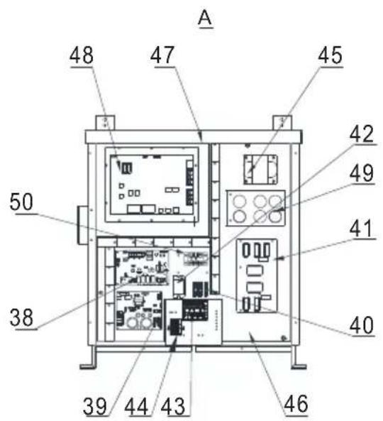
HP5211ET3 / HP5251ET3 / HP5301ET3
| Nr. | Betegnelse Ref. HP5211ET3 HP5251ET3 HP5301ET3 | ||||
| 1 | Viftemotor DC | HWX20000330381 | √ | √ | Gjelder ikke |
| HWX20000330402 Gjelder ikke Gjelder ikke | √ | ||||
| 2 | Deksel for motoren HWX20000220320 | √ √ | √ | ||
| 3 | ∅vre panel | HWX80900737 | √ | √ | Gjelder ikke |
| HWX80900718 Gjelder ikke Gjelder ikke | √ | ||||
| 4 | Deksel for høyre side | HWX80705113 | √ | √ | Gjelder ikke |
| HWX80705110 Gjelder ikke Gjelder ikke | √ | ||||
| 5 | / / / / | / | |||
| 6 | Beskyttelsesplate | HWX32002210071 | √ | √ | Gjelder ikke |
| HWX32004210137 Gjelder ikke Gjelder ikke | √ | ||||
| 7 | Trykktilkobling 90 mm - 1/2" | HWX20000140153 | √ √ | √ | |
| 8 | Elektronisk starter | HWX20000140449 | √ | Gjelder ikke | Gjelder ikke |
| HWX20000140442 Gjelder ikke | √ | Gjelder ikke | |||
| HWX20000140401 Gjelder ikke Gjelder ikke | √ | ||||
| 9 | Filter ∅12.9-∅12.9 (∅28) | HWX20000140027 | √ √ | √ | |
| 10 | Trykktilkobling 95 mm - 7/16" | HWX20000140512 | √ √ | √ | |
| 11 | Trykktilkobling 40 mm - 1/2" | HWX20000140150 | √ √ | √ | |
| 12 | 4-veisventil | HWX20011491 | √ √ | √ | |
| 13 | Trykksensors | HWX20000360274 | √ √ | √ | |
| 14 | Fordamper/luft/vann-temperatursensor 5k 800mm | HWX20003202 | √ √ | √ | |
| 15 | Kompressorutladningssonde 50k-600 mm HWX20000320145 | √ √ | √ | ||
| 16 | Sensor for vannstrømning | HWX83000069 | √ √ | √ | |
| 17 | // / / | / | |||
| 18 | Fremre panel | HWX80900739 | √ | √ | Gjelder ikke |
| HWX80900710 Gjelder ikke Gjelder ikke | √ | ||||
| 19 | Berøringsskjerm med farger | HWX95005310612 | √ √ | √ | |
| 20 | Trappe elektrisk tilgang | HWX20000220247 | √ √ | √ | |
| 21 | Elektrisk boks panel | HWX80702644 | √ | √ | Gjelder ikke |
| HWX80702645 Gjelder ikke Gjelder ikke | √ | ||||
| 22 | Høytrykkspressostat NC 3.2 MPa/4.4 MPa | HWX20000360187 | √ √ | √ | |
| 23 | Strømningsbegrenser NO 0.15 MPa/0.05 MPa HWX20000360054 | √ √ | √ | ||
| 24 | // / / | / | |||
| 25 | Kondensator Titanium/PVC | HWX32002120023 | √ | Gjelder ikke | Gjelder ikke |
| HWX32016120012 Gjelder ikke | √ | Gjelder ikke | |||
| HWX32016120011 | Gjelder ikke Gjelder ikke | √ | |||
| 26 | // / / | / | |||
| 27 | Kompressor | HWX80100069 | √ | √ | Gjelder ikke |
| HWX30101000006 Gjelder ikke Gjelder ikke | √ | ||||
| 28 | Deksel for venstre side | HWX80705114 | √ | √ | Gjelder ikke |
| HWX80705111 | Gjelder ikke Gjelder ikke | √ | |||
| 29 | // / / | / | |||
| 30 | Firkantet koblingsstykke med gjenge 50 mm | HWX20031379 | √ √ | √ | |
| 31 | PVC bøy ∅ 50 mm | HWX20011359 | √ √ | √ | |
| 32 | Vertikalt støtte høyre/venstre | HWX80702346 | √ | √ | Gjelder ikke |
| HWX80702656 Gjelder ikke Gjelder ikke | √ | ||||
| 33 | Vinget fordamper | HWX80600429 | √ | Gjelder ikke | Gjelder ikke |
| HWX32003120028 Gjelder ikke | √ | Gjelder ikke | |||
| HWX32004120013 Gjelder ikke Gjelder ikke | √ | ||||
| 34 | Deksel for baksiden | HWX80705115 | √ | √ | Gjelder ikke |
| HWX80705112 Gjelder ikke Gjelder ikke | √ | ||||
| 35 | // / / | / | |||
6. VEDLEGG (fortsetter)
HP5211ET3 / HP5251ET3 / HP5301ET3
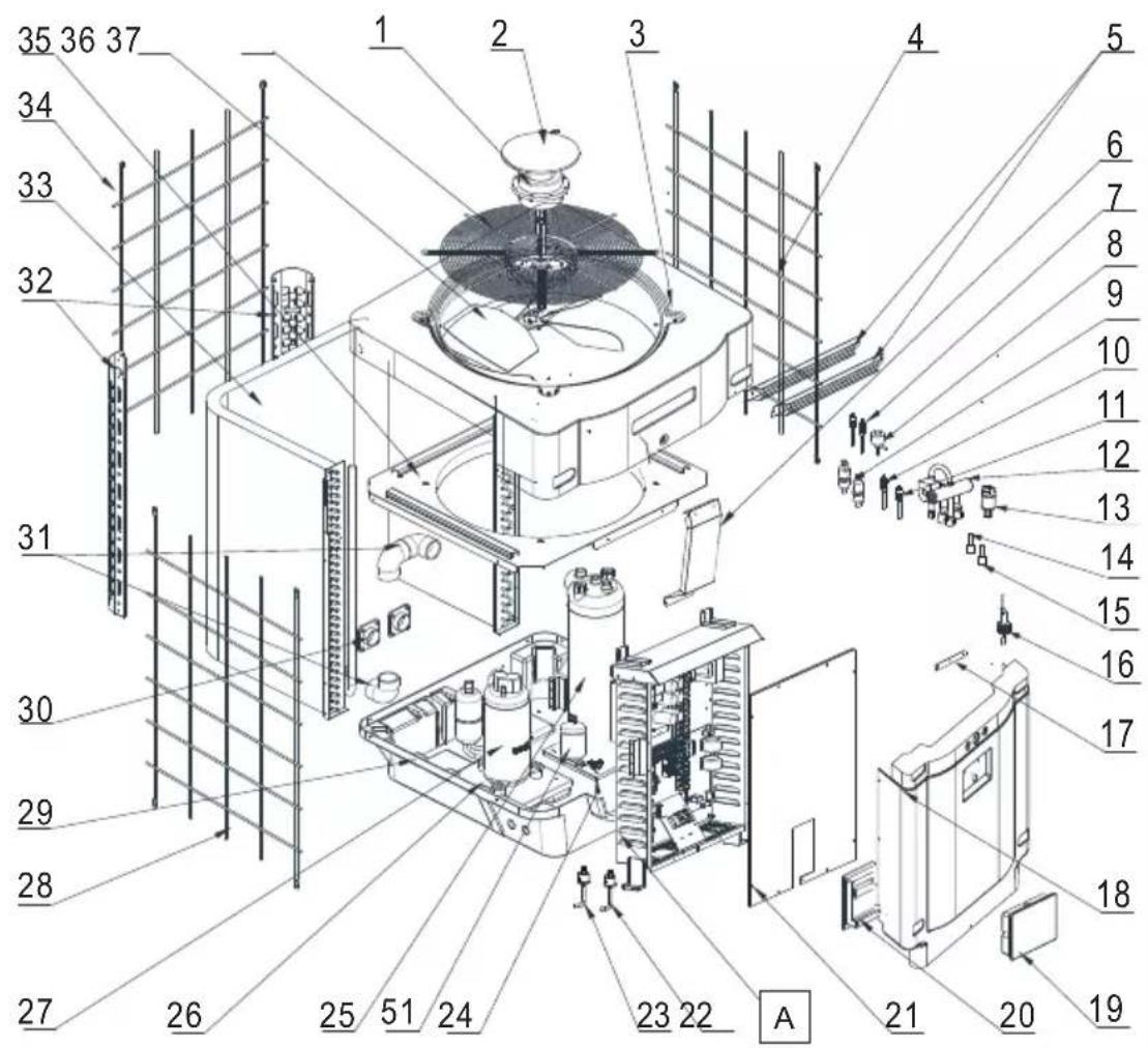

6. VEDLEGG (fortsetter)
HP5211ET3 / HP5251ET3 / HP5301ET3
| Nr. | Betegnelse Ref. HP5211ET3 HP5251ET3 HP5301ET3 | ||||
| 36 | Vifteproprell ∅ 560 mm HWX35072195 | √ | √ | Gjelder ikke | |
| Vifteproprell ∅ 600 mm HWX20000270057 Gjelder | ikke Gjelder ikke | √ | |||
| 37 | Beskyttelsesgitter for viften | HWX32003210142 | √ | √ | Gjelder ikke |
| HWX80700160 Gjelder ikke Gjelder ikke | √ | ||||
| 38 | Elektronisk hovedkort | HWX72200033211E | √ | Gjelder ikke Gjelder ikke | |
| HWX72200033251E Gjelder ikke | √ | Gjelder ikke | |||
| HWX72200033301E Gjelder ikke Gjelder ikke | √ | ||||
| 39 | Kort for Inverter vifte | HWX82300485 | √√ | √ | |
| 40 | Terminal 4 tilkoplinger | HWX20003909 | √√ | √ | |
| 41 | Filterkort | HWX82300074 | √√ | √ | |
| 42 | Relé K2 | HWX20000360297 | √√ | √ | |
| 43 | Terminal R-R-T-N-GND | HWX20000390180 | √√ | √ | |
| 44 | 4-polet klemme | HWX20000390046 | √√ | √ | |
| 45 | Spole reaktans | HWX20000370030 | √√ | √ | |
| 46 / | / | / | / | / | |
| 47 | / | / | / | / | / |
| 48 | Kort for Inverter kompressor | HWX82300112 | √ | √ | Gjelder ikke |
| HWX302010000012 | Gjelder ikke Gjelder ikke | √ | |||
| 49 | Kondensatorkort | HWX302010000014 | √√ | √ | |
| 50 | Terminal L-N-GND reaktans | HWX20000390223 | √√ | √ | |
| 51 | Beholder med væske HWX20000140579 Gjelder ikke | √ | √ | ||
6. VEDLEGG (fortsetter)
6. VEDLEGG (fortsetter)
| Feil Feilkoder Beskrivelse Løsning | |||
| Feil i temperatursensor til vanninnløp | P01 | Sensoren er åpen eller det er en kortslutning. | Sjekk den blå AIN6 kontakten på kortet, og mål motstanden på sonden. Hvis den er mindre enn 100 Ω eller større enn 500 kΩ, må du skifte den ut. |
| Feil i temperatursensor til vannutløp | P02 | Sjekk den røde AIN7 kontakten på kortet, og mål motstanden på sonden. Hvis den er mindre enn 100 Ω eller større enn 500 kΩ, må du skifte den ut. | |
| Feil på avrimingssensor P04 | Sjekk AIN9 kontakten på kortet, og mål motstanden på sonden. Hvis den er mindre enn 100 Ω eller større enn 500 kΩ, må du skifte den ut. | ||
| Feil på sensor til utendørstemperatur | P05 | Sjekk den gule AIN8 kontakten på kortet, og mål motstanden på sonden. Hvis den er mindre enn 100 Ω eller større enn 500 kΩ, må du skifte den ut. | |
| Feil på kompressor aspirationssensor | P07 | Sjekk den grønne AIN5 kontakten på kortet, og mål motstanden på sonden. Hvis den er mindre enn 100 Ω eller større enn 500 kΩ, må du skifte den ut. | |
| Feil motstand 6.8 kΩ P09 | Sjekk AIN11 kontakten på kortet og mål motstanden, skift ut hvis Motstanden < 6.8 kΩ | ||
| Feil på kompressorutladningsføler P081 | Sjekk den svarte AIN12 kontakten på kortet, og mål motstanden på sonden. Hvis den er mindre enn 100 Ω eller større enn 500 kΩ, må du skifte den ut. | ||
| For høy utladetemperatur P082 Utladetemperatur > 120°C | Mål utladetemperaturen ved utgangen av kompressoren, hvis den målte temperaturen < 120°C, må sonden skiftes ut.Ta en test for ikke-kondensbare gasser | ||
| Høytrykksbeskyttelse | E01 | Sensoren er åpen eller det er en kortslutning. | Sjekk CN30/HP koblingen på kortet eller bytt sensor |
| Sjekk vannmengden | |||
| Sjekk detektoren for vannmengde | |||
| Sjekk at ventilene er åpne | |||
| Sjekk by-passventilen | |||
| Sjekk at fordamperen ikke er tett | |||
| Vanntemperaturen er for høy | |||
| Kondensproblemer etter vedlikeholdsarbeid, tøm hele kjølekretsen | |||
| For stor væskemengde, tøm noe væske ut i en flaske | |||
| Lavtrykksbeskyttelse | E02 | Sensoren er åpen eller det er en kortslutning. | Sjekk AI/DI03 koblingen på kortet eller bytt sensor |
| Stor lekkasje med kjølevæske, foreta en lekkasjetest med detektor | |||
| Luftmengden er for lav, sjekk hastigheten til vifterotasjonen | |||
| Sjekk at fordamperen ikke er tett, rengjør den på overflaten | |||
6. VEDLEGG (fortsetter)
6. VEDLEGG (fortsetter)
6.6 Lagringsbase
natural_image
Exterior view of a modern office building (no signage)
HP5171DT3HP5211DT3HP5251DT3HP5301DT3HP5211ET3HP5251ET3HP5301ET3
natural_image
Technical line drawing of a mechanical device with internal components and an upward arrow indicator (no text or symbols)natural_image
Technical line drawing of a mechanical device with internal components and an upward arrow indicator (no text or symbols)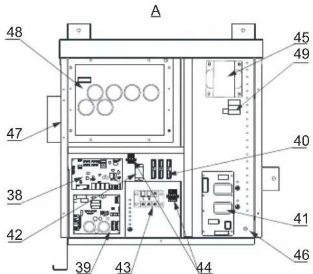


natural_image
Simple line drawing of a trash bin with crossed lines indicating no waste or restriction (no text or symbols)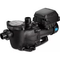
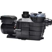
- Raccordement hydraulique
- INTERFACE UTILISATEUR (suite)
- LEGENDE
- ANNEXES (suite)
- Raccordements priorité chauffage Pompe Triphasé
- HP5171DT3 / HP5211DT3 / HP5251DT3 / HP5301DT3
- CONDITIONS DE GARANTIE
- CONTENTS
- GENERAL INSTRUCTIONS - SAFETY 1
- SPECIFICATIONS 5
- INSTALLATION AND CONNECTION 9
- USER INTERFACE 17
- MAINTENANCE AND WINTERISING 25
- APPENDIX 26
- GENERAL INSTRUCTIONS - SAFETY
- Authorised personnel
- GENERAL INSTRUCTIONS - SAFETY (continued)
- This product contains refrigerant gas R32
- Installation conditions
- Instructions for servicing - maintenance
- Instructions for winterising
- Conditions for use
- SPECIFICATIONS (continued)
- Operating range
- Dimensions
- Models:
- INSTALLATION AND CONNECTION
- Functional Diagram
- INSTALLATION AND CONNECTION (continued)
- Pompe à chaleur
- Hydraulic connection
- Electrical connection
- Initial start-up
- Water flow setting
- USER INTERFACE
- General presentation
- USER INTERFACE (continued)
- OFF Mode
- ON Mode
- Setting the Date and Time
- Timer function settings
- Setting and visualisation of the set point
- In Mode "OFF" or Mode "ON"
- Locking and unlocking the touch screen
- SILENT function settings
- Manual Activation
- Maintenance
- Winterising
- APPENDIX
- Electrical diagrams
- HP5171DT3
- REMARKS:
- APPENDIX (continued)
- Heating priority wiring for monophasic pump
- Heating priority wiring for three phases pump
- Exploded view and spare parts
- Troubleshooting guide
- Recording base
- This data is available for 60 days.
- WARRANTY CONDITIONS
- End of life of the device
- SUMHEAT FULL INVERTER
- LEYENDA
- LEGENDA
- INSTALLATIE EN AANSLUITING
- Basisschema
- In Modus "OFF" of "ON"
- APPENDICI (segue)
- VEDLIKEHOLD OG VINTERKLARGJ∅RING 25
- GENERELLE FORHOLDSREGLER (fortsetter)
- Dette produktet inneholder kjølegassen R32
- Betingelser for installering
- SPESIFIKASJONER (fortsetter)
- Driftsområde
- Dimensjoner
- INSTALLERING OG TILKOBLING
- Skjematisk diagram
- INSTALLERING OG TILKOBLING (fortsetter)
- Varmepumpe
- Vanntilkobling
- Elektrisk tilkobling
- BRUKERGRENSESNITT (fortsetter)
- OFF-modus
- ON-modus
- VEDLEGG (fortsetter)
- MERKNADER
- Kobling med prioritet på enfaset varmepumpe
- Kobling med prioritet på trefaset varmepumpe
- Lagringsbase
Brand : HAYWARD
Model : SumHeat Fi
Category : Pump