
S.Line Pro Fi - Pump HAYWARD - Free user manual and instructions
Find the device manual for free S.Line Pro Fi HAYWARD in PDF.

| Product Type | Pool Heat Pump |
| Brand | Hayward |
| Model | S.Line Pro Fi (HP5081DT3LV / HP5111DT3LV / HP5151DT3LV) |
| Power Supply | 230 V ~ 50 Hz Single Phase |
| Refrigerant | R32, charge 0.45 to 0.65 kg depending on model |
| Heating Capacity (min-max) | 1.77 – 15.66 kW depending on model and conditions |
| COP (max-min) | 13.30 – 4.31 depending on model and conditions |
| Dimensions (L x W x H) | 1011 x 430 x 621.5 mm (HP5081/5111) or 1030 x 480 x 776 mm (HP5151) |
| Weight | 61 kg (HP5081/5111) / 87 kg (HP5151) |
| Hydraulic Connection | Ø 50 mm (inlet and outlet) |
| Nominal Water Flow | 3.5 – 6.7 m³/h depending on model |
| Sound Level at 1 m | 45.1 – 54.1 dB(A) depending on model |
| Outdoor Temperature Range (heating) | -7 °C to +35 °C |
| Water Temperature Range | +8 °C to +40 °C (cooling), +12 °C to +32 °C (heating) |
| Operating Mode | Heating, Cooling, Automatic, Silent |
| Technology | Full Inverter with Mitsubishi DC Compressor |
| Control | Digital Touch Screen + Bluetooth Application EyesPool Inverter Connect |
| Programming | On/Off Timers, Silent Mode Timer |
| Maintenance | Annual evaporator cleaning, check fittings and condensate |
| Winterizing | Drain the condenser, close the bypass, cover the unit |
| Warranty | 2 years (excluding wear parts and frost damage) |
| Certifications | CE, compliant with electrical and environmental standards |
Frequently Asked Questions - S.Line Pro Fi HAYWARD
User questions about S.Line Pro Fi HAYWARD
0 question about this device. Answer the ones you know or ask your own.
Ask a new question about this device
Download the instructions for your Pump in PDF format for free! Find your manual S.Line Pro Fi - HAYWARD and take your electronic device back in hand. On this page are published all the documents necessary for the use of your device. S.Line Pro Fi by HAYWARD.
USER MANUAL S.Line Pro Fi HAYWARD
natural_image
Exterior view of a modern HVAC unit with star-shaped decorative patterns (no visible text or symbols)
natural_image
Exterior view of a modern industrial air conditioning unit (no visible text or symbols)
3.3 Raccordement hydraulique
flowchart
graph LR
    A["Device Display"] --> B{Condition: 09:00 OFF ON, OUT °C, IN 26.0}
    B --> C["1 min"]
    C --> D["Hand Icon with Arrow pointing to a button"]
    D --> E["Arrow to right"]
4. INTERFACE UTILISATEUR (suite)
CONDITIONS DE GARANTIE
natural_image
Exterior view of a modern industrial air conditioning unit (no visible text or symbols)
1. PREFACE 1
2. Technical Specifications 4
2.1 Heat pump technical data 4
2.2 Operating range 5
2.3 Dimensions 6
3. INSTALLATION AND CONNECTION 7
3.1 Functional Diagram 7
3.2 Heat pump unit 7
3.3 Hydraulic connection 8
3.4 Electrical connection 9
3.5 Initial start-up 10
4. USER INTERFACE 12
4.1 Overview 12
4.2 Water flow setting 14
4.3 Setting the clock 15
4.4 Setting the On/Off timers 15
4.5 Adjusting the SILENT mode of the Timer function 17
4.6 Bluetooth pairing - Remote control 18
4.7 Operating mode selection 19
4.8 Settings and viewing the setpoint 20
4.9 Locking and unlocking the touch screen 21
5. MAINTENANCE AND WINTERISING 22
5.1 Maintenance 22
5.2 Winterising 22
6. APPENDIX 23
6.1 Electrical diagrams 23
6.2 Heating priority wiring for monophasic pump 25
6.3 Exploded view and spare parts 26
6.4 Troubleshooting guide 30
6.5 Warranty 33
1. PREFACE
Thank you for purchasing the Hayward heat pump for swimming pools. The S.LINE PRO heat pump has been designed to strict manufacturing standards meeting the highest levels of quality required.
S.LINE PRO heat pumps offer you exceptional performance throughout your bathing season by adapting wattage, power usage and noise levels to the heating requirements of your swimming pool thanks to FULL INVERTER control logic.

Read the instructions in this manual carefully before using the device.
S.LINE PRO heat pumps are designed exclusively to heat swimming pool water; do not use this equipment for any other purpose.
This manual includes all the necessary information for installation, trouble-shooting and maintenance.
Read this manual carefully before opening the unit or doing any maintenance work on it. The manufacturer of this product shall on no account accept any liability for injury to a user or damage to the unit further to any errors made during installation, trouble-shooting or unnecessary maintenance. It is particularly important to follow the instructions given in this manual at all times.
Otherwise the guarantee will be voided.
1. PREFACE (continued)

Safety instructions

This device contains R32.
Never use a refrigerant other than R32. Any other gaseous body mixed with R32 could cause abnormally high pressure and lead to a failure or pipes bursting and injuring people.
During repairs or maintenance operations, use copper tubes that comply with Standard EN 12375-1 (May 2020) and the European Pressure Equipment Directive 97/23 / EC.
As the heat pump is pressurized, never pierce the pipes or attempt any brazing. There is a risk of explosion.
Never expose the device to flames, sparks or other sources of ignition. It could explode and cause serious or even fatal injuries.

The heat pump is designed exclusively for installation outside buildings.
- If kept in storage, the heat pump should be kept in a well-ventilated room with a floor area of more than A_(m^2) as calculated by the following formula:
M is the quantity of refrigerant in the device in kg, and h0 is the storage height. If stored no the floor, h0 = 0.6 m. - The unit must be installed by qualified personnel.
- Do not install the heat pump on a support that risks intensifying the unit's vibrations.
- Make sure the support provided for the unit is strong enough to bear the weight of the unit.
- Do not install the heat pump anywhere liable to amplify its noise level or anywhere where its noise could disturb neighbours.
- All the electrical connections must be fitted by a professional qualified electrician in accordance with the standards in force in the country of installation, see §3.4.
- Shut off the main power supply and disconnecting switch before doing any electrical work. Forgetting to do so could cause electrocution.
- Before installing the unit, check that the earth cable is not cut or disconnected.
$$ A _ {\min} = (M / (2. 5 \times 0. 2 2 7 5 9 \times h 0)) ^ {2}. $$
1. PREFACE (continued)
- Connect and properly tighten the power cable. A loose connection could damage electrical components.
- Exposing the heat pump to water or a humid atmosphere could cause electrocution. Be very careful.
- If you detect a fault or any abnormal situation, do not install the heat pump and contact your dealer immediately.
- All maintenance work should be done at the recommended intervals, as specified in this manual.
• Repairs must be carried out by qualified personnel. - Only use OEM spare parts.
- Never use a cleaning method other than the one recommended in this manual.
Important information concerning the refrigerant used
This makes contains fluorinated greenhouse gases regulated by the Kyoto protocol. Do not release these gases into the atmosphere.
Type of refrigerant: R32
GWP(1) value: 675, based in the 4th report of the IPCC.
The quantity of refrigerant, based on the F-Gas regulation no. 517/2014, is stated on the unit's rating plate.
Period checks for leaks of refrigerant may be required by European or local legislation. Please contact your local dealer for more information.
(1) Global warming potential
2. TECHNICAL SPECIFICATIONS
2.1 Heat pump technical data
| Models S.LINE PRO HP5081DT3LV HP5 | 111DT3LV HP5151DT3LV | |||
| Supply voltage V | 220V-240V ∼/1ph/50Hz | |||
| Refrigerant / R32 | ||||
| Load kg 0.45 0.50 0.65 | ||||
| Mass in teqCO2 | / 0.30 0.34 0.44 | |||
| Leak check frequency / No specific frequency, but an annual check is recommended | ||||
| Min--Max heating capacity(a) | kW | 2.83 -- 8.16 | 1.95 -- 10.90 | 5.27 -- 15.66 |
| Min--Max electric input power(a) | kW | 0.212 -- 1.19 | 0.150 -- 1.92 | 0.457 -- 2.80 |
| Min--Max continuous current rating(a) | A | 1.41 -- 5.20 | 1.05 -- 8.49 | 2.04 -- 12.28 |
| Max--Min continuous power (COP)(a) | / | 13.30 -- 6.81 | 12.92 -- 5.67 | 11.53 -- 5.59 |
| Min--Max heating capacity(b) | kW | 1.77 -- 5.91 | 1.86 -- 8.40 | 3.81 -- 11.67 |
| Min--Max electric input power(b) | kW | 0.31 -- 1.28 | 0.30 -- 1.83 | 0.588 -- 2.71 |
| Max--Min continuous power (COP)(b) | / | 5.70 -- 4.62 | 6.20 -- 4.59 | 6.48 -- 4.31 |
| Maximum continuous current | A | 6.50 | 10.30 | 14 |
| Fuse rating | gG | 10 | 12 | 16 |
| Circuit-breaker curve C | C | 10 | 12 | 16 |
| Starting current | A | < maximum continuous current | ||
| Hydraulic connection | mm | 50 mm | ||
| Nominal water flow(a) | m3/h | 3.50 4.60 6.70 | ||
| Max. loss of head on water | kPa | 8 | 5 | 10 |
| Compressor | / | DC Inverter MITSUBISHI ELECTRIC | DC Inverter Mitsubishi | |
| Type | / | Twin rotary | Twin rotary | |
| Quantity | / | 1 | ||
| Coil resistance at 20°C | Ohm | 1.91 +/- 5% | 0.95 +/- 5% | |
| Fan | / | Axial | ||
| Quantity | 1 | |||
| Diameter | mm | 405 | 500 | |
| Number of blades | / | 3 | ||
| Motor | / | DC Inverter | ||
| Quantity | / | 1 | ||
| Rotation speed | rpm | 500 -- 800 | 500 -- 900 | 500 -- 750 |
| Silent mode speed | rpm | 500 | 500 | 500 |
| Sound pressure level at 1 meter | dB(A) | 45.1 | 48.6 | 54.1 |
| Sound pressure level at 10 meters | dB(A) | 27.9 | 31.6 | 36.9 |
| Unit's net dimensions (L-W-H) | mm | 1011 / 430 / 622 | 1025 / 480 / 768 | |
| Weight | kg 61 61 | 87 | ||
(a) Dry air 27°C - Relative humidity 78% - Water inlet temperature 26°C.
(b) Dry air 15°C - Relative humidity 71% - Water inlet temperature 26°C
2. TECHNICAL SPECIFICATIONS (continued)
2.2 Operating range
Use the swimming pool heat pump unit within the following ranges of temperature and humidity to ensure safe and efficient operation.
Heating mode  ng mode ng mode |  | |
| Outside temperature -7°C – +35°C | +7°C – +43°C | |
| Water temperature +12°C – +32°C | +8°C – +40°C | |
| Relative humidity < 80% < 80% | ||
| Setting range from the set point +15°C – +32°C | +8°C – +32°C |

If the temperature or humidity does not correspond to these conditions, the security measures could be activated and the swimming pool heat pump unit may no longer work.

The maximum heating temperature is set at 32^ C to prevent damage to the liners. Hayward cannot be held responsible if used at a temperature above +32^ C.
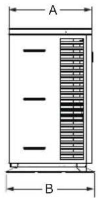
2. TECHNICAL SPECIFICATIONS (continued)
2.3 Dimensions
Models:
HP5081DT3LV / HP5111DT3LV / HP5151DT3LV
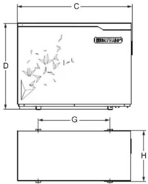

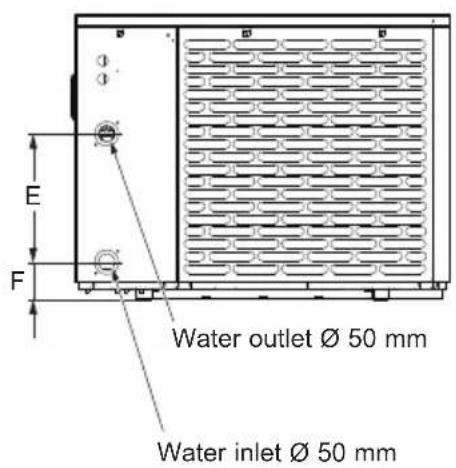
Unit: mm
| Size\Type | HP5081DT3LV / HP5111DT3LV HP5151DT3LV |
| A 393 453 | |
| B 430 480 | |
| C 1011 1030 | |
| D 621.5 776 | |
| E 350 350 | |
| F 97.5 102 | |
| G 625 645 | |
| H 406 456 |
3. INSTALLATION AND CONNECTION
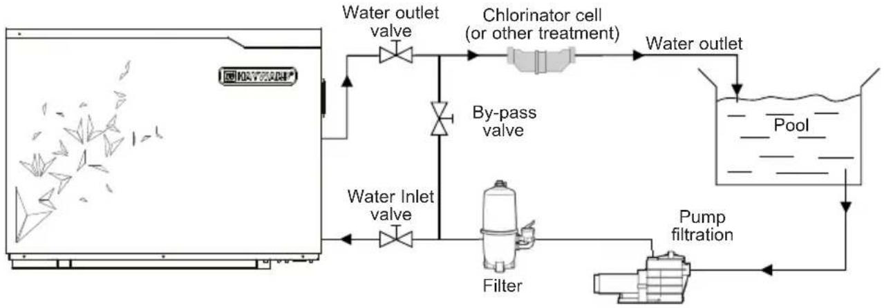
3.1 Functional Diagram
flowchart
graph LR
    A["Water inlet valve"] --> B["Water outlet valve"]
    B --> C["Chlorinator cell (or other treatment)"]
    C --> D["Water outlet"]
    D --> E["Pump filtration"]
    E --> F["Filter"]
    F --> G["Water inlet valve"]
    G --> A
    style A fill:#f9f,stroke:#333
    style B fill:#ccf,stroke:#333
    style C fill:#cfc,stroke:#333
    style D fill:#fcc,stroke:#333
    style E fill:#cff,stroke:#333
    style F fill:#ffc,stroke:#333
    style G fill:#cfc,stroke:#333
Note: The swimming pool heat pump unit is sold without any treatment or filtration equipment. The components presented in the diagram are spare parts to be supplied by the installer.
3.2 Heat pump unit

Place the heat pump outdoors and away from any enclosed technical space.
Placed under a shelter, the minimum required distances mentioned below must be respected in order to avoid any risk of air recirculation and a deficiency in the unit's overall performance.
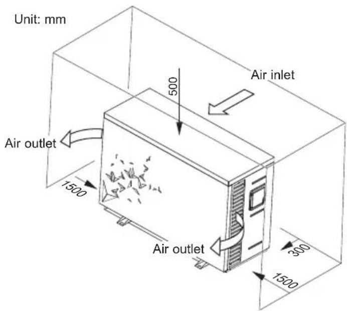
3. INSTALLATION AND CONNECTION (continued)

It is advised to install the unit on a dissociated cement block or a mounting bracket designed for this use and to set up the unit on the supplied rubber bushing (fastenings and washers not supplied).
The maximum installation distance between the unit and the swimming pool is 15 metres.
The total length of the piping to and from the unit is 30 metres.
Insulate both the above ground and buried hydraulic piping.
The heat pump must be installed at a minimum distance from the pool in compliance with NF C 15-100 (3.5 m from the water for France) or in compliance with installation standards applicable in other countries.
Do not install the heat pump close to a heat source.
For installation in snowy regions we recommend sheltering the machine to avoid snow accumulating on the evaporator.
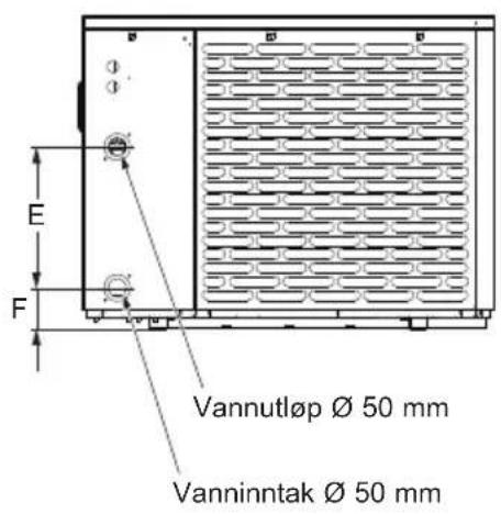
3.3 Hydraulic connection
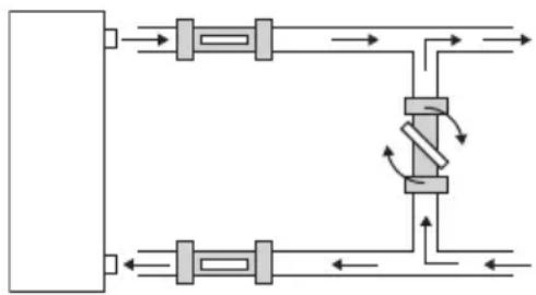
The unit is supplied with two 50 mm ∅ union connections. Connect the water inlet to the heat pump coming from the filtration group then connect the water outlet to the heat pump at the water conduit going to the pool (see diagram below).
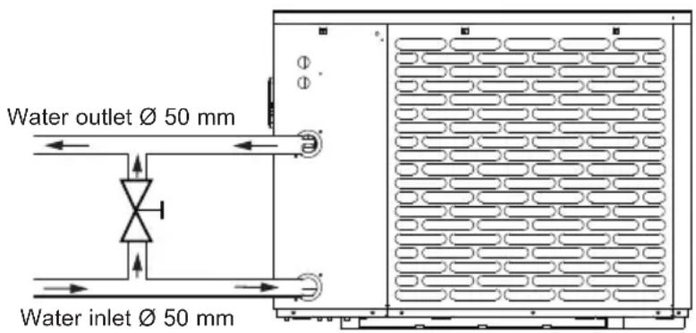
Install a by-pass valve between the heat pump entrance and exit.

If an automatic distributor or an electrolyser is used, it should be installed imperatively after the heat pump with the goal of protecting the titanium condenser against an elevated concentration of chemicals.

Be sure to install the by-pass valve and the supplied union connections at the water inlet and outlet level in order to simplify purging during the winter period and to facilitate access when disassembling for maintenance.
3. INSTALLATION AND CONNECTION (continued)
3.4 Electrical connection

Electrical installation and wiring for this equipment must be in conformity with local installation standards.
| F NF C15-100 GB BS7671:1992 | ||
| D DIN VDE 0100-702 EW EVHS-HD 384-7-702 | ||
| A ÖVE 8001-4-702 H MSZ 2364-702/1994/MSZ 10-553 1/1990 | ||
| E UNE 20460-7-702 1993,RECBT ITC-BT-31 2002 | M MSA HD 384-7-702.S2 | |
| IRL Wiring Rules + IS HD 384-7-702 PL PN-IEC 60364-7-702:1999 | ||
| I CEI 64-8/7 CZ CSN 33 2000 7-702 | ||
| LUX 384-7.702 S2 | SK | STN 33 2000-7-702 |
| NL NEN 1010-7-702 | SLO | SIST HD 384-7-702.S2 |
| P RSIUEE TR T$ IEC 60364-7-702 | ||

Verify that the available electrical power supply and the network frequency correspond to the required operating current taking into account the appliance's specific location, and the current required to supply any other appliance connected to the same circuit.
HP5081DT3LV / HP5111DT3LV / HP5151DT3LV 230V ∼ +/- 10 % 50 Hz 1 Phase
See the corresponding wiring diagram in the appendix. Three connections are designed for the power supply and two are for controlling the filter pump (Enslavement).
3. INSTALLATION AND CONNECTION (continued)

The electrical power supply must have, when appropriate, a fuse protection device like a feed motor (gG) or C curve circuit breaker as well as a differential circuit breaker 30mA (see following table).
| Models | HP5081DT3LV HP5111DT3LV HP5151DT3LV | |||
| Power supply | V/Ph/Hz | 230V~ 50Hz | 230V~ 50Hz | 230V~ 50Hz |
| gG type fuse calibre A | 10 gG 1 | 2 gG 16 gG | ||
| Curve C circuit breaker | A 10 | C 12 C 16 C | ||
| Cable section | mm ^2 | 3G 2,5 3G 2,5 | 3G 2,5 | |

Use an RO 2V/R 2V or equivalent power cord.

The cables sections are given for a maximum length of 25 m. They must however be checked and adjusted according to the installation conditions.

Always shut down the main power supply before opening the electrical control box.
3.5 Initial start-up
Start-up procedure - After installation is complete, follow these steps:
1) Rotate the fans by hand to verify that they can turn freely by hand, and that the turbine is correctly affixed to the motor shaft.
2) Ensure that the unit is connected correctly to the main power supply (see the wiring diagram in the appendix).
3) Activate the filtration pump.
4) Verify that all water valves are open and that the water flows toward the unit before switching on the heating or cooling mode.
5) Verify that the drainage hose is correctly affixed and that it causes no obstructions.
6) Activate the unit power supply, then press the On/Off button ⏻ on the control panel.
7) Make sure the alarm or lock symbols are not displayed. If need be, see the trouble-shooting guide (see § 6.4).
3. INSTALLATION AND CONNECTION (continued)
8) Set the water flow using the by-pass valve (see § 2.1 and 4.2), as provided for by each model, to obtain an Entry/Exit temperature of 2^ C.
9) After running for several minutes, verify that the air exiting the unit is cool (between 5 and 10°).
10) With the unit operating, turn off the filter pump. The unit should automatically turn off and display error code E03 (See § 6.4).
11) Allow the unit and the pool pump to run 24 hours per day until the desired water temperature has been reached. When the set water inlet temperature is reached, the unit will turn off. It will automatically restart (as long as the pool pump is running) if the pool temperature is at least 0.5^ C below the set temperature.
Water flow switch - The unit is equipped with a flow switch that turns on the heat pump when the pool filtration pump is running, and deactivates it when the filtration pump is out of order. If the water is low, the E03 alarm code will appear on the regulator (See § 6.4).
Time delay - The unit is equipped with a time delay of 3 minutes in order to protect the control circuit components, to eliminate restart cycling and contactor chatter. Thanks to this time delay, the unit automatically restarts approximately 3 minutes after each control circuit interruption. Even a brief power interruption will activate the restart time delay.
4. USER INTERFACE
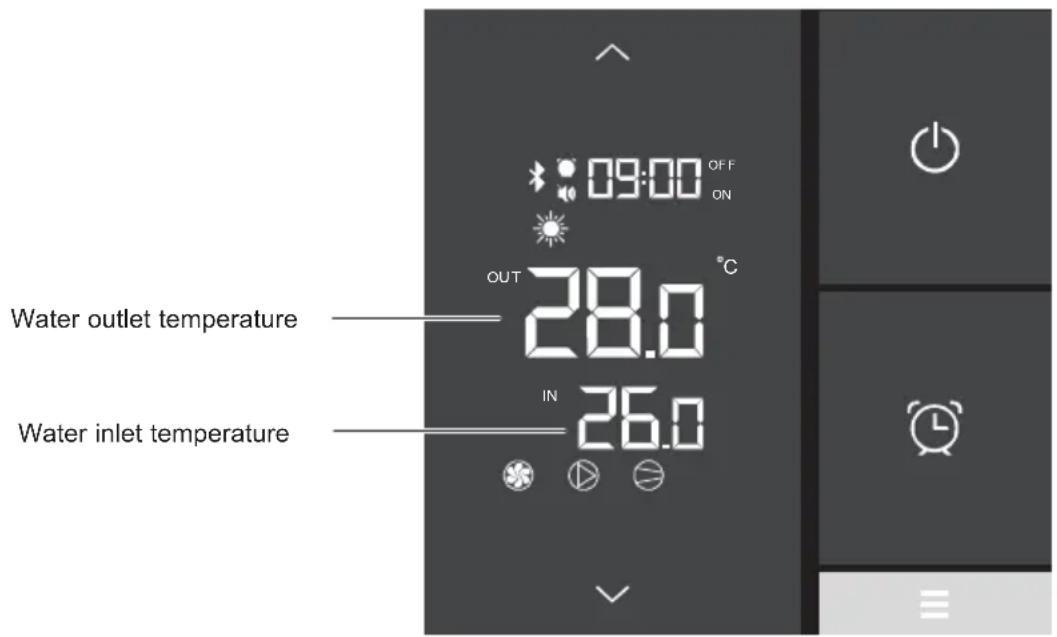
4.1 Overview
The heat pump is equipped with a digital control panel with a touch screen, electronically connected and pre-set at the factory in heating mode.
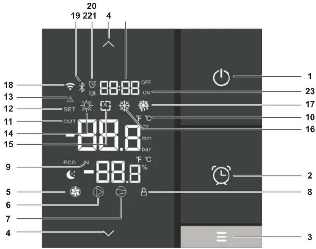
Key
| 1 | [ZX][XXAR] Back | |
| 2 | Setting the Time and Timers | |
| 3 | Operating mode selection | |
| 4 | [4XST] | Scroll Up / Down, +°C / -°C |
| 5 | Fan ON | |
| 6 | Dry contact OUT2 ON | |
| 7 | Core sensor ON | |
| 8 | Locked screen | |
| 9 | Water input | |
| 10 |  | Celsius / Fahrenheit |
| 11 | Water output | |
| 12 | Setting advanced settings |
| 13 | System default |
| 14 | Heating mode |
| 15 | Automatic mode |
| 16 | Cooling mode |
| 17 | Derost mode |
| 18 | N/A |
| 19 | Bluetooth Connection |
| 20 | Timelset |
| 21 | Silence mode / Timer light |
| 22 | Time of timers |
| 23 | Timers set for Off and On |
| 13 | System default |
| 14 | Heating mode |
| 15 | Automatic mode |
| 16 | Cooling mode |
| 17 | Derost mode |
| 18 | N/A |
| 19 | Bluetooth Connection |
| 20 | Timelset |
| 21 | Silence mode / Timer light |
| 22 | Time of timers |
| 23 | Timers set for Off and On |
4. USER INTERFACE (continued)
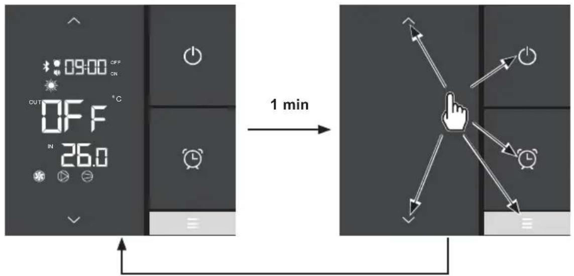
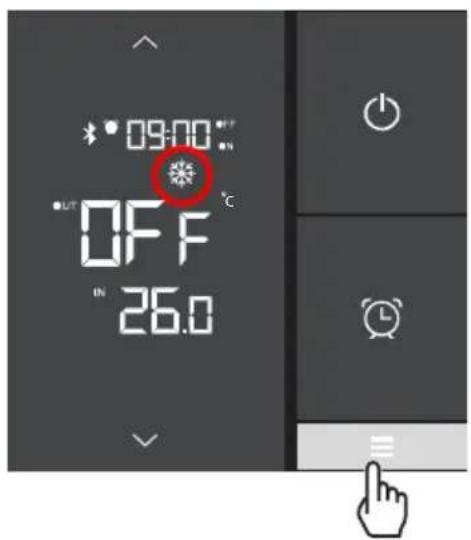
OFF mode
When the heat pump is on standby (OFF mode), the indication OFF is displayed on the control screen and the screen switches to save-energy mode after one minute.
flowchart
graph LR
    A["Digital Display with ON/OFF status, timer, alarm clock"] -->|1 min| B["Arrow pointing to a finger icon with directional arrows to screen"]
    style A fill:#f9f,stroke:#333
    style B fill:#ccf,stroke:#333
To return to the full display, press any button.
ON mode
When the heat pump is operating or being set (ON mode) the water inflow and outflow temperatures are displayed on the control screen and the screen switches to save-energy mode after one minute.
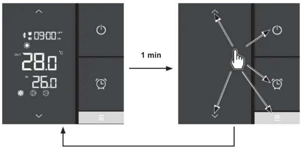
To return to the full display, press any button.
4.2 Water flow setting
With the water entry and exit valves being open, adjust the by-pass valve in order to obtain a difference of 2^ C between the water inlet and outlet temperatures (see principle diagram § 3.1).
You can verify the switch by seeing the entry/exit temperatures directly on the control panel.
Then, adjust your by-pass in order to obtain a difference of 2^ C between the input and the output.
Press to exit the menu.
- Opening the "bypass" valve generates a lower flow rate in the heat pump exchanger, resulting in an increase in the inlet / outlet temperature difference.
- Closing the "bypass" valve generates a greater flow rate in the heat pump exchanger, resulting in a reduction in the inlet / outlet temperature difference.
flowchart
graph TD
    A["Top Section"] --> B["Valve"]
    B --> C["Bottom Section"]
    C --> D["Valve"]
    D --> E["Bottom Section"]
    E --> F["Valve"]
    F --> G["Bottom Section"]
    G --> H["Valve"]
    H --> I["Bottom Section"]
    I --> J["Valve"]
    J --> K["Bottom Section"]
    K --> L["Valve"]
    L --> M["Bottom Section"]
    M --> N["Valve"]
    N --> O["Bottom Section"]
    O --> P["Valve"]
    P --> Q["Bottom Section"]
    Q --> R["Valve"]
    R --> S["Bottom Section"]
    S --> T["Valve"]
    T --> U["Bottom Section"]
    U --> V["Valve"]
    V --> W["Bottom Section"]
    W --> X["Valve"]
    X --> Y["Bottom Section"]
    Y --> Z["Valve"]
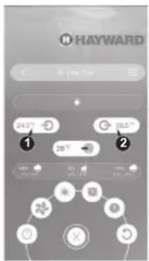
The setting can be checked by viewing the inlet / outlet temperatures (1 - 2) directly on the "EyesPool Inverter Connect" application (see § 4.6).
4. USER INTERFACE (continued)
4.3 Setting the clock
At the end of the settings, press Ⓜ confirm.
The saving of the settings is automatic after 5 seconds of inactivity.
- Press : the time display blinks.
- Press : the hours blink. Set the hours using the and buttons.
- Press then set the minutes using the and buttons.
- Confirm by pressing .
4.4 Setting the On/Off timers
Setting this function is necessary if you would like to run the heat pump for a shorter period than what is defined by the filtration clock. Therefore, you can program a deferred start and an anticipated stop or simply stop a certain timeframe from running (at night, for example).
It is possible to set one Start Timer (ON) and one Stop Timer (OFF).
Setting the Timer - Start (ON)
- Press 2 seconds, until the icon blinks.
- Press : the display blinks ().
- Press to set the hours using the and buttons.
- Press to set the minutes using the and buttons.
- Confirm by pressing then to return to the main screen.
The settings are saved automatically after 20s of inactivity.
The setting of the minutes is done in steps of 10 minutes
The ON indication under the time display on the main screen indicates that the Start (ON) Timer is set.
4. USER INTERFACE (continued)
Setting the Timer - Stop (OFF)
- Press 102 seconds, until the
- Press : the display blinks ().
- Press : the display blinks ().
- Press to set the hours using the and buttons.
- Press to set the minutes using the and buttons.
- Confirm by pressing then to return to the main screen.
The settings are saved automatically after 20s of inactivity.
The setting of the minutes is done in steps of 10 minutes
The OFF indication above the time display on the main screen indicates that the Stop (OFF) Timer is set.
Consulting Timers
- Press for 2 seconds, until the icon blinks.
- Press : the display of the starting time blinks.
- Press : the display of the stopping time blink 19:10 OFF
- Press to return to the main screen.
The Icon is displayed on the main screen when a Start Timer and/or Stop Timer is set.
Deleting Start (ON) and Stop (OFF) Timers
- Press 12 seconds, until the icon blinks.
- Press twice: the start hours blink .
- Press to delete the start Timer .
At the end of step 3 press 📊 to go back to the main screen or move on to step 4 to continue.
- Press to access the stop time . 19:10 OFF
- Press : the stop hours blink .
- Press to delete the stop Timer .
- Press to return to the main screen.
4. USER INTERFACE (continued)
Deleting the Timer Stop (OFF)
- Press for 2 seconds, until the icon blinks.
- Press twice: the start hours blink .
- Press to access the stop time .
- Press : the stop hours blink .
- Press to delete the stop Timer .
- Press to return to the main screen.


4.5 Adjusting the SILENT mode of the Timer function
SILENCE mode enables the heat pump to be used in economic and very silent mode when the heating needs are low (maintaining the pool temperature or need for ultra-silent operation).
Setting the SILENT mode of the Timer
- Press for 2 seconds, until the icon-blinks.
- Press : the icon blinks.
- Press : the display blinks.
- Press ☐ set the starting time using the and buttons.
- Press then : the display blinks.
- Press set the stop time using the and buttons.
- Press to confirm then to return to the main screen.
Deleting the SILENT mode of the Timer
- Press for 2 seconds, until the icon-blinks.
- Press : the icon blinks.
- Press : the display of the starting time 09:10 on blinks.
- Press : only the hours blink.
- Press : the display blinks.
- Press to return to the main screen.
The deletion of the Start Timer systematically causes the deletion of the Stop Timer.
The setting step is "hour to hour".
4. USER INTERFACE (continued)
Consulting the SILENT mode Timer
- Press 10/2 seconds, until the icon blinks.
- Press : the icon-blinks.
- Press ① view the start time.
- Press to view the stop time.
- Press to return to the main screen.
The moon is displayed on the main screen when a Start Timer or Stop Timer is set for the SILENCE mode.
4.6 Bluetooth pairing - Remote control
The heat pump is equipped with the Bluetooth function.
Thanks to the "EyesPool Inverter Connect" application, you can use your smartphone as a remote control to control your heat pump within a limit of 10 m in open space.
To have this function Bluetooth
▶ Download the "EyesPool Inverter Connect" application for free from

▶ Create an account on the application.
▶ Follow the video instructions (links below) to pair your smartphone with the heat pump:
https://www.hayward.fr/article/tutoriels-hayward/s-line-pro-bluetooth-appairage

4. USER INTERFACE (continued)
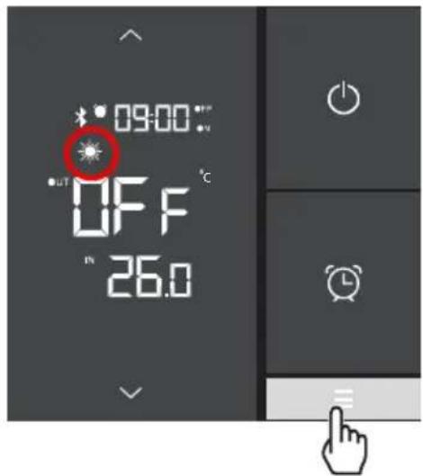
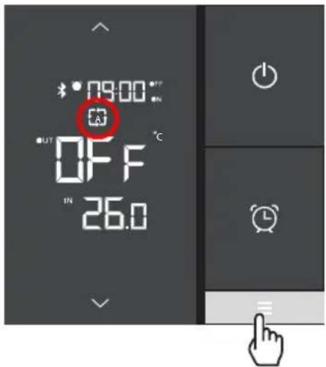
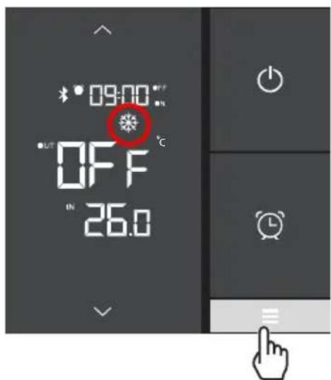
4.7 Operating mode selection
Heating - Automatic - Cooling

If the heat pump is set to Heat Only or Cool Only mode by the installer, changing the mode is no longer available.
Press the button to change the mode: Heating - Automatic - Cooling.
Heating Automatic
Cooling
4. USER INTERFACE (continued)
4.8 Settings and viewing the setpoint
Desired water temperature
The setpoint can be changed either in OFF or in ON mode with an accuracy of 0.5^ C.
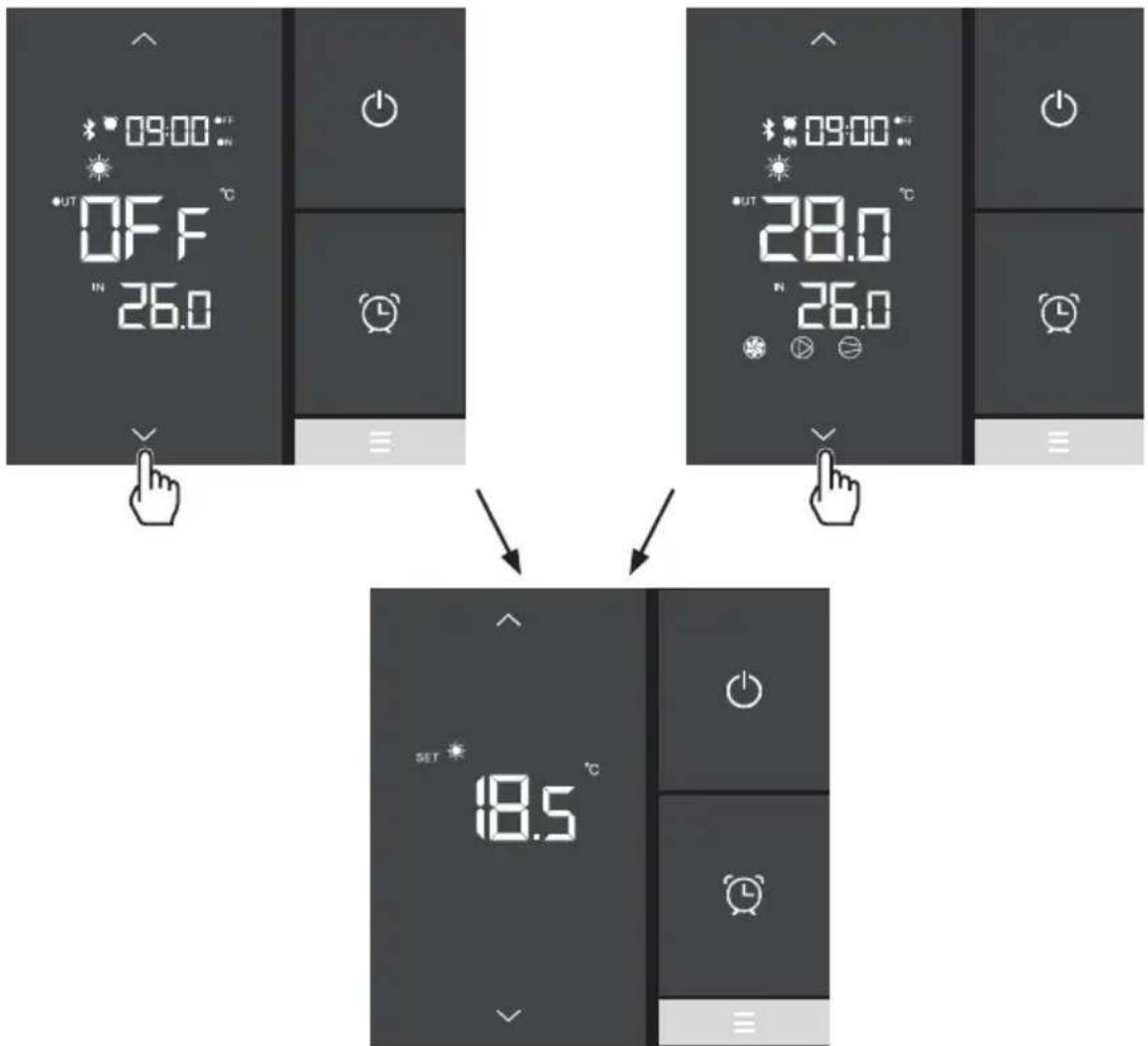
- Press or to make the setpoint blink.
- Press or to set the desired setpoint.
- Press to confirm or to cancel.
The settings are saved automatically after 5 seconds of inactivity.

It is recommended to never exceed 30^ C to avoid alteration of the liners.
4. USER INTERFACE (continued)
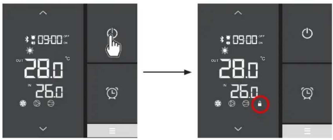
4.9 Locking and unlocking the touch screen
The screen can be locked or unlocked either in ON or in OFF mode.
- Press for 5 seconds until the icon appears.
• To unlock, press until the icon disappears.
5.1 Maintenance
These maintenance operations must be carried out once per year in order to guarantee the longevity and the good working condition of the heat pump.
- Clean the coil with the help of a soft brush or jet of air or water (Warning, never use a high pressure cleaner).
- Verify that the drains flow well.
- Verify the tightening of the hydraulic and electrical connections
- Verify the hydraulic sealing of the condenser.
- Have the leak-tightness of the cooling circuit to the leak detector checked by an accredited professional.

Before any maintenance operation, the heating pump must be disconnected from any electrical current source. The maintenance operations must only be carried out by personnel that is qualified and authorised to handle liquid refrigerants.
5.2 Winterising
- Put the heat pump in "OFF" mode.
- Cut the power supply to the heat pump.
- Empty the condenser with the help of the drain to avoid any risk of deterioration. (high risk of freezing).
- Close the by-pass valve and unscrew the entry/exit connection unions.
- Eliminate the maximum amount of residual stagnant water from the condenser with the help of an air gun.
- Close the water entry and exit areas of the heating pump to avoid introducing foreign bodies.
- Cover the heating pump with a dedicated winterising case.

Any damage caused by poor winterising maintenance will lead to cancellation of the warranty.
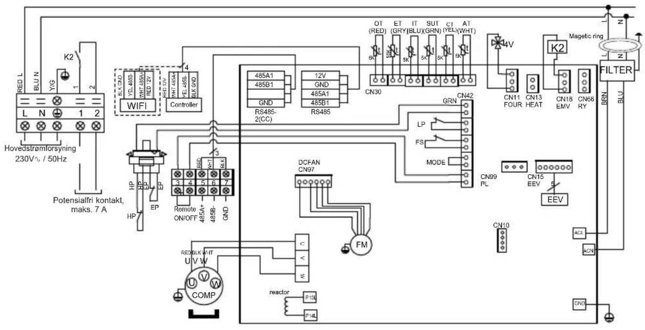
6. APPENDIX
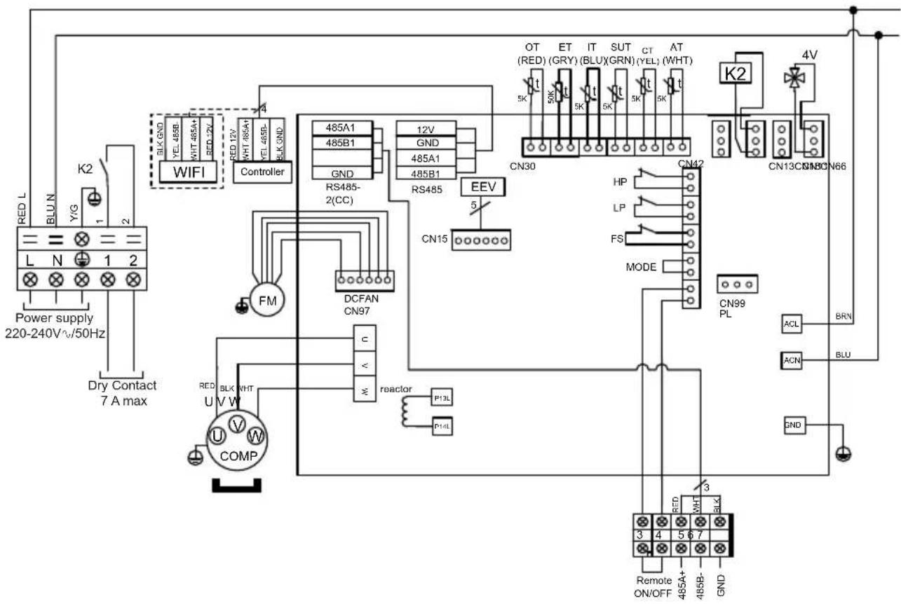
6.1 Electrical diagrams
HP5081DT3LVM / HP5111DT3LV
flowchart
graph TD
    A["Power supply 220-240V~50Hz"] --> B["BLK GND"]
    B --> C["WIFI"]
    C --> D["Controller"]
    D --> E["485A1 485B1"]
    D --> F["RS485-2(CC)"]
    D --> G["485A1 485B1"]
    D --> H["RS485"]
    H --> I["CN15"]
    I --> J["DCFAN CN97"]
    J --> K["FM"]
    K --> L["COMP U V W"]
    L --> M["BLK WHT"]
    M --> N["reactor P13L"]
    N --> O["P14L"]
    O --> P["CON99 PL"]
    P --> Q["ACN BLU"]
    Q --> R["BRN"]
    R --> S["4V"]
    S --> T["CN13CN18CN66"]
    T --> U["K2"]
    U --> V["AT (WHT)"]
    V --> W["CT (YEL)"]
    W --> X["SUT (BLUX)"]
    X --> Y["IT (GRY)"]
    Y --> Z["OT (RED)"]
    Z --> AA["4V"]
    AA --> AB["GNND"]
    AB --> AC["Remote ON/OFF"]
    AC --> AD["3"]
    AD --> AE["485A+"]
    AD --> AF["485B-"]
    AD --> AG["GND"]
REMARKS
AT: AIR TEMPERATURE SENSOR
COMP: COMPRESSOR
CT: EVAPORATOR TEMPERATURE SENSOR
EEV: ELECTRONIC EXPANSION VALVE
FM: FAN MOTOR
FS: WATER FLOW SWITCH
HP: HIGH PRESSURE SWITCH
IT: WATER INLET TEMPERATURE SENSOR
LP: LOW PRESSURE SWITCH
OT: OUTLET WATER TEMPERATURE SENSOR
SUT: SUCTION TEMPERATURE SENSOR
4V: 4 WAYS VALVE
K2: DRY CONTACT 7 A MAX
ET: DISCHARGE TEMPERATURE SENSOR
: OPTION
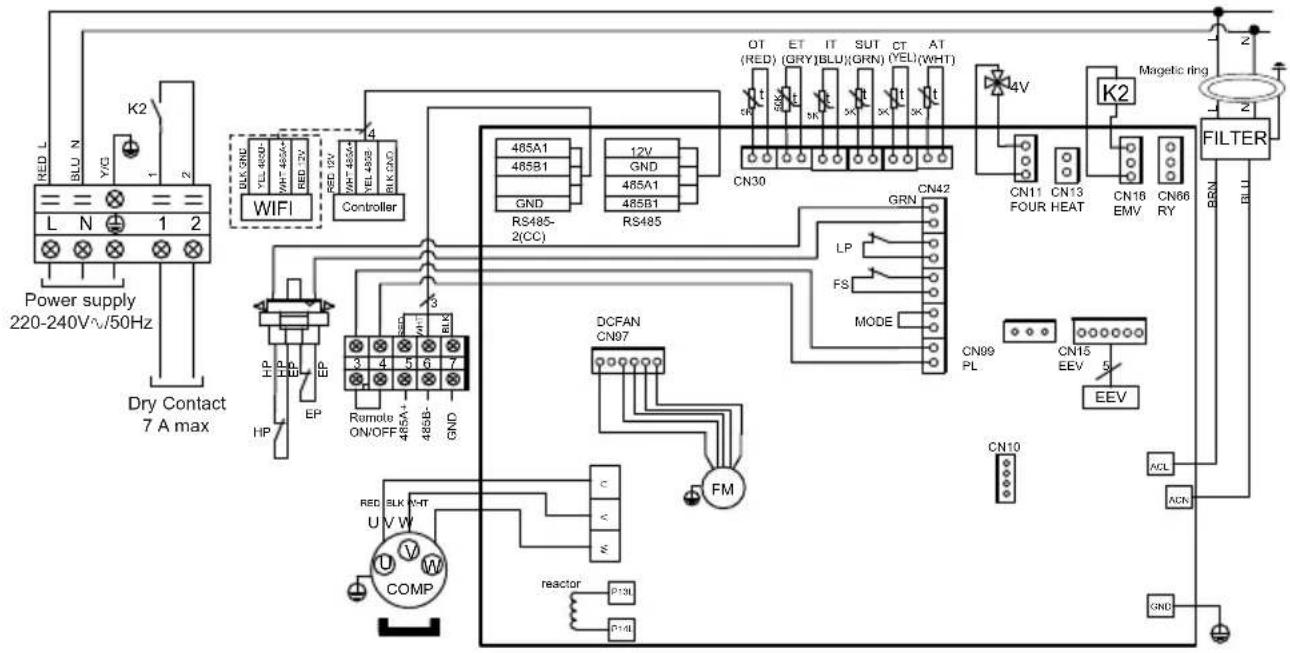
6. APPENDIX (continued)
HP5151DT3LV
flowchart
graph TD
    A["Power supply 220-240V^.50Hz"] --> B["WIFI"]
    B --> C["Controller"]
    C --> D["485A1 485B1 GND"]
    C --> E["RS485-2(CC)"]
    D --> F["485A1 485B1 GND"]
    E --> G["RS485"]
    F --> H["CN30"]
    G --> I["CN30"]
    H --> J["GN7"]
    I --> K["GN7"]
    J --> L["GN7"]
    K --> M["GN7"]
    L --> N["GN7"]
    M --> O["GN7"]
    N --> P["GN7"]
    O --> Q["GN7"]
    P --> R["GN7"]
    Q --> S["GN7"]
    R --> T["GN7"]
    S --> U["GN7"]
    T --> V["GN7"]
    U --> W["GN7"]
    V --> X["GN7"]
    W --> Y["GN7"]
    X --> Z["GN7"]
    Y --> AA["GN7"]
    Z --> AB["GN7"]
    AA --> AC["GN7"]
    AB --> AD["GN7"]
    AC --> AE["GN7"]
    AD --> AF["GN7"]
    AE --> AG["GN7"]
    AF --> AH["GN7"]
    AG --> AI["GN7"]
    AH --> AJ["GN7"]
    AI --> AK["GN7"]
    AJ --> AL["GN7"]
    AK --> AM["GN7"]
    AL --> AN["GN7"]
    AM --> AO["GN7"]
    AN --> AP["GN7"]
    AO --> AQ["GN7"]
    AP --> AR["GN7"]
    AQ --> AS["GN7"]
    AR --> AT["GN7"]
    AS --> AU["GN7"]
    AT --> AV["GN7"]
    AU --> AW["GN7"]
    AV --> AX["GN7"]
    AW --> AY["GN7"]
    AX --> AZ["GN7"]
    AY --> BA["KN10"]
    AZ --> BB["KN10"]
    BA --> BC["KN10"]
    BB --> BD["KN10"]
    BC --> BE["KN10"]
    BD --> BF["KN10"]
    BE --> BG["KN10"]
    BF --> BH["KN10"]
    BG --> BI["KN10"]
    BH --> BJ["KN10"]
    BI --> BK["KN10"]
    BJ --> BL["KN10"]
    BK --> BM["KN10"]
    BL --> BN["KN10"]
    BM --> BO["KN10"]
    BN --> BP["KN10"]
    BO --> BQ["KN10"]
    BP --> BR["KN10"]
    BQ --> BS["KN10"]
    BR --> BT["KN10"]
    BS --> BU["KN10"]
    BT --> BV["KN10"]
REMARKS
AT: AIR TEMPERATURE SENSOR
COMP: COMPRESSOR
CT: EVAPORATOR TEMPERATURE SENSOR
EEV: ELECTRONIC EXPANSION VALVE
FM: FAN MOTOR K2: DRY CONTACT 7 A MAX
FS: WATER FLOW SWITCH
HP: HIGH PRESSURE SWITCH
IT: WATER INLET TEMPERATURE SENSOR
LP: LOW PRESSURE SWITCH
OT: OUTLET WATER TEMPERATURE SENSOR
SUT: SUCTION TEMPERATURE SENSOR
4V: 4 WAYS VALVE
ET: DISCHARGE TEMPERATURE SENSOR
OPTION
6. APPENDIX (continued)
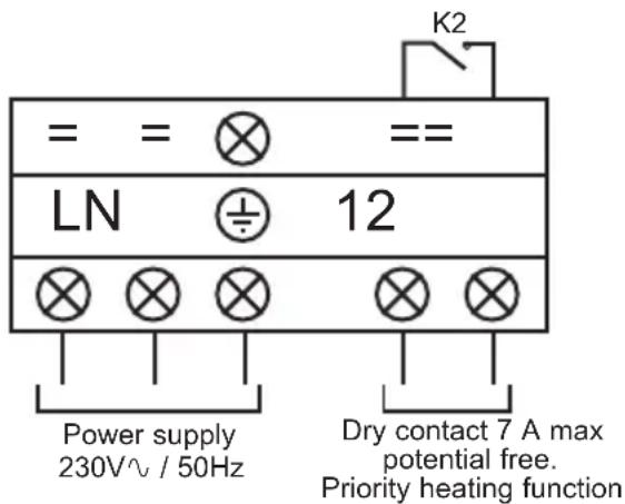
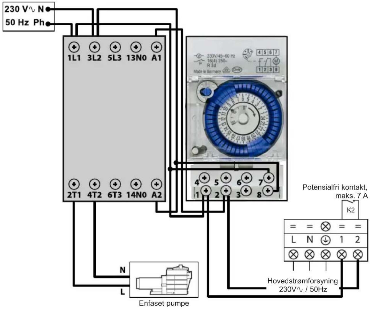
6.2 Heating priority wiring for monophasic pump

Terminals 1 and 2 deliver a potential-free dry contact, 230V / 50Hz , no polarity. Wire terminals 1 and 2 as indicated in the diagram above, to activate the operation of the filtration pump in 2-minute cycles each hour if the temperature of the pool is lower than the set point.

Never connect the power supply of the filtration pump directly to terminals 1 and 2.
6. APPENDIX (continued)
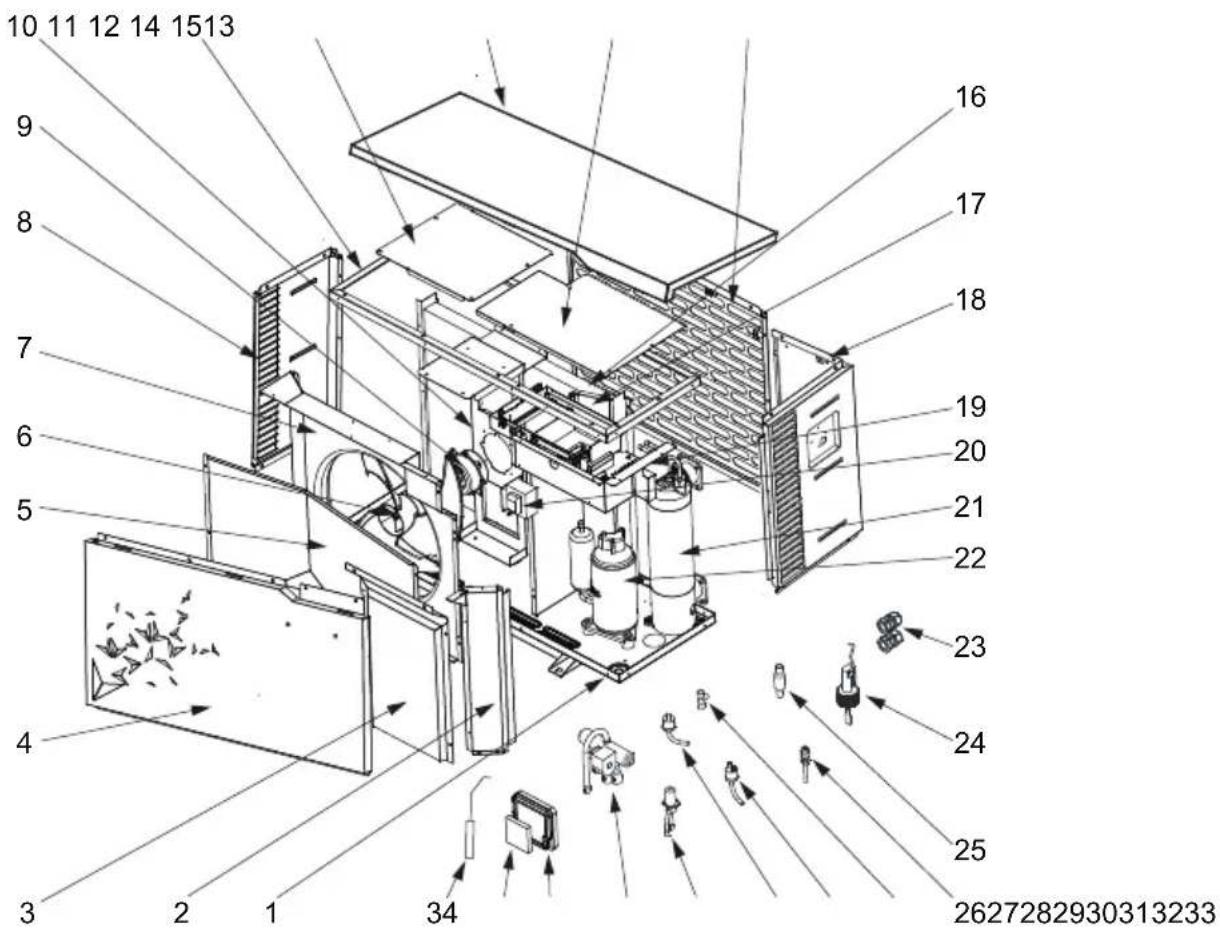
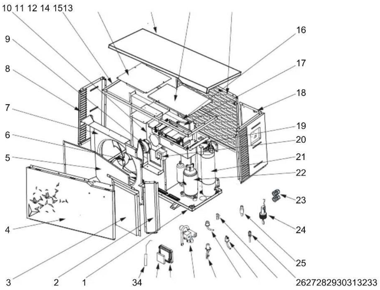
6.3 Exploded view and spare parts
HP5081DT3LV / HP5111DT3LV / HP5151DT3LV
6. APPENDIX (continued)
| Mark | Description Ref. HP5081DT3LV HP5111DT3LV | HP5151DT3LV | |||
| 1 | / | / | / | / | / |
| 2 | / | / | / / / | ||
| 3 | / | / | / | / | / |
| 4 | Front panel | HWX80715842 | √ | √ | n/a |
| HWX80715857 | n/a n/a | √ | |||
| 5 | / | / | / / / | ||
| 6 | Fan blade | HWX301030000006 | √ | √ | n/a |
| HWX20000270004 | n/a n/a | √ | |||
| 7 | / / / | / | / | ||
| 8 | Left panel | HWX80713420 | √ | √ | n/a |
| HWX80713423 | n/a | n/a | √ | ||
| 9 | DC ventilator motor | HWX80200018 | √ | √ | n/a |
| HWX20000330132 | n/a | n/a | √ | ||
| 10 | Motor bracket | HWX80708597 | √ | √ | n/a |
| HWX80709977 | n/a | n/a | √ | ||
| 11 | / | / | / / / | ||
| 12 | / | / | / / / | ||
| 13 | Top cover | HWX80708601 | √ | √ | n/a |
| HWX80709984 | n/a n/a | √ | |||
| 14 | / | / | / / / | ||
| 15 | Back panel | HWX80710829 | √ | √ | n/a |
| HWX80710966 | n/a n/a | √ | |||
| 16 | Fin coil | HWX80600849 | √ | n/a n/a | |
| HWX80600781 | n/a | √ | n/a | ||
| HWX80600835 | n/a n/a | √ | |||
| 17 | / | / | / | / | / |
| 18 | Right panel | HWX80713421 | √ | √ | n/a |
| HWX80713424 | n/a n/a | √ | |||
| 19 | / | / / / | |||
| 20 | Reactance | HWX82500020 | √ | √ | n/a |
| HWX82500021 | n/a | n/a | √ | ||
| 21 | Titanium/PVC condenser | HWX80600939 | √ | n/a n/a | |
| HWX80600940 | n/a | √ | √ | ||
| HWX80600096 | n/a | n/a | √ | ||
| 22 | Compressor | HWX20000110448 | √ | √ | n/a |
| HWX80100046 | n/a n/a | √ | |||
| 23 | Cable Gland | HWX20012249 | √ | √ | n/a |
| HWX20012238 | n/a n/a | √ | |||
| 24 | Water flow detector HWX83000068 | √ √ | √ | ||
| 25 | Filter ∅9.7-∅9.7 (∅19) HWX20000140178 | √ | √ | n/a | |
| Filter ∅9.7-∅9.7 (∅28) HWX20041444 | n/a n/a | √ | |||
| 26 | Pressure tap 40mm-1/2" HWX20000140150 | √ √ | √ | ||
| 27 | Connector T ∅9.52-2 x∅6.35(T) x 1.0 | HWX30403000002 | √ | √ | n/a |
| Connector T ∅6.5-2 x ∅6.5(T) x 0.75 | HWX20001460 | n/a n/a | √ | ||
| 28 | Low pressure switch NO 0.30MPa/0.15MPa | HWX20000360157 | √ √ | √ | |
| 29 | High pressure switch NC 3.2MPa/4.4MPa | HWX20013605 | √ √ | √ | |
| 30 | Electronic expansion valve | HWX81000011 | √ | √ | n/a |
| HWX81000017 | n/a n/a | √ | |||
| 31 | 4 ways valve | HWX20041437 | √ | √ | n/a |
| HWX20000140485 | n/a n/a | √ | |||
| 32 | Controller mount | HWX80901004 | √ √ | √ | |
| 33 | LCD Bluetooth controller | HWX72200312 | √ | √ | √ |
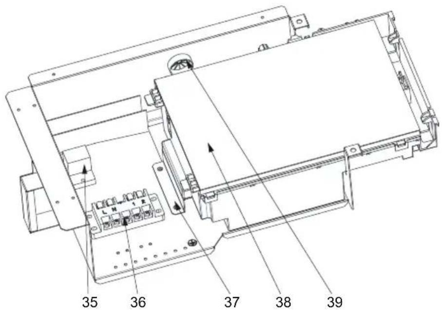
6. APPENDIX (continued)
HP5081DT3LV / HP5111DT3LV / HP5151DT3LV


6. APPENDIX (continued)
| Mark | Description Ref. HP5081DT3LV HP5111DT3LV | HP5151DT3LV | |||
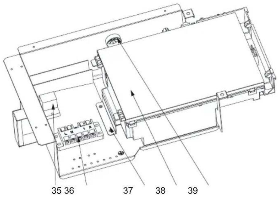
| 34 | Water outlet sensor 5k-410mm HWX83000050 | √ √ | √ | ||
| Water inlet sensor 5k-850mm HWX83000052 | √ | √ | √ | ||
| Compressor discharge probe 50k-660mm HWX83000026 | √ √ | √ | |||
| Compressor aspiration sensor 5k-560mm HWX83000044 | √ | √ | n/a | ||
| Compressor aspiration sensor 5k-760mm HWX83000053 | n/a n/a | √ | |||
| De-icing sensor 5k-680mm HWX83000051 | √ | √ | n/a | ||
| De-icing sensor 5k-1040mm HWX83000045 | n/a | n/a | √ | ||
| Temperature sensor 5k-350mm HWX83000049 | √ √ | √ | |||
| 35 | K2 relay HWX20000360297 | √ | √ | √ | |
| 36 | Terminal block L-N-GND -5 connections 4mm ^2 | HWX40003901 | √ √ | √ | |
| 37 | / | / | / | / | / |
| 38 | Printed circuit board Driver | HWX72200168SL08 | √ | n/a n/a | |
| HWX72200168SL11 | n/a | √ | n/a | ||
| HWX72200168SL15 | n/a | n/a | √ | ||
| 39 | / | / | / | / | / |
6. APPENDIX (continued)
6.4 Troubleshooting guide

Certain operations must be conducted by an authorised technician.
If a fault occurs, the following information appears on the screen:
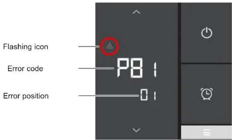
If there are several errors, press or to scroll through the list of error codes. See the table below.
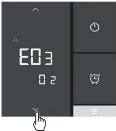

Once the problem has been resolved, the error is cancelled automatically and the triangle disappears.
6. APPENDIX (continued)
| Problem | Error codes | Description Solution | |
| Inlet water probe fault (IT) PO1 | The sensor is open or short-circuiting | Check the connections on the extension connector or replace the sensor | |
| Outlet water probe fault (OT) PO2 | |||
| Exterior temperature probe fault (AT) PO4 | |||
| De-icing sensor fault (CT) PO5 | |||
| Compressor aspiration sensor fault (SUT) | PO7 | ||
| Compressor discharge sensor fault (ET) | PO81 | ||
| High Pressure fault E01 | The sensor is open or short-circuiting | Check the connections on the extension connector or replace the sensor | |
| Check the water flow | |||
| Check the water flow detector | |||
| Check valve opening | |||
| Check the by-pass | |||
| Check the evaporator is not clogged | |||
| Water temperature too hot | |||
| Incondensable problem after maintenance, empty and evacuate the cooling circuit | |||
| Fluid load too high, remove fluid into a liquid bottle | |||
| Low pressure fault E02 | The sensor is open or short-circuiting | Check the connections on the extension connector or replace the sensor | |
| Major refrigerant leak, use to detector to find the leak | |||
| Air flow too low, check the ventilator rotation speed | |||
| Check the evaporator is not clogged, clean its surface |
6. APPENDIX (continued)
| Problem | Error codes | Description Solution | |
| Flow detector defect E03 The sensor is open or short-circuiting | Check the CN29/OVT connections on the board or replace the sensor | ||
| Insufficient water, check operation of the filtration pump | |||
| Check opening of the stop valves | |||
| Check the by-pass setting | |||
| Inlet/Outlet temperature difference >13°C E05 Applicable in Cold mode only | Insufficient water, check operation of the filtration pump | ||
| Check opening of the stop valves | |||
| Check the by-pass setting | |||
| Anti-freezing protection E07 Water outlet temperature <4°C | Stop the heat pump and empty the condenser. Risk of freezing | ||
| Communication problem | E08 | No communication between the electronic board and the user interface | Check the connections - see the wiring diagram |
| Level 1 anti-freezing protection E19 | 2°C < Water Temperature < 4°C and Air Temperature < 0°C | Stop heat pump operation, empty the condenser to prevent freezing; by default the heat pump starts the filtration pump to prevent icing over | |
| Level 2 anti-freezing protection E29 | Water Temperature < 2° and Air Temperature < 0°C | Stop heat pump operation, empty the condenser to prevent freezing; by default the heat pump starts the filtration pump to prevent icing over | |
| Fan motor fault F03 / Motor blocked or connection fault | Check for smooth rotation; check the CN97/DCFAN connection; replace the motor | ||
| Fan motor fault F05 / Connection fault | Check the DCFAN/CN97 connection; replace the motor | ||
| Outside temperature too low EP Operating limit reached Stop the heat pump | |||
| The heat pump will not start | - - - OFF | Contact (5-6) Remote On/Off Open | Close contact (5-6) Remote On/Off (see wiring diagram) |
6. APPENDIX (continued)
6.5 Warranty
WARRANTY CONDITIONS
All HAYWARD products are guaranteed to be free from manufacturing or material faults for a period of two years as from the date of purchase. Any claim made under the terms of the warranty must be accompanied by a dated proof of purchase. We therefore recommend that you keep your invoice.
The HAYWARD warranty is limited to the repair or replacement, at HAYWARD's discretion, of faulty products, provided they have been used under normal conditions, as described in their user guide, and that the product has not been modified in any way and has been used only with HAYWARD components and parts. Frost and chemical damage are not covered.
No other costs (transportation, labour, etc.) are covered by the warranty.
HAYWARD cannot be held liable for any direct or indirect damage caused by the incorrect installation, connection or operation of a product.
Please contact your retailer if you want to make a claim under the terms of the warranty and request the repair or replacement of an item. No equipment returned to our factory will be accepted without our prior written agreement.
Worn parts are not covered by the warranty.
Page left intentionally blank

HAYWARD®
S.Line Pro Fi
UNIDAD DE BOMBA DE CALOR PARA PISCINAS
natural_image
Exterior view of a modern industrial HVAC unit with star-shaped decorative patterns (no visible text or symbols)
flowchart
graph LR
    A["Device Display: 09:00 OFF ON, OUT °C, IN 26.0"] -->|1 min| B["Device Interaction: Hand icon with arrows indicating finger movement"]
    style A fill:#f9f,stroke:#333
    style B fill:#bbf,stroke:#333
flowchart
graph LR
    A["Digital Display Temperature: 28.0°C"] -->|1 min| B["Hand gestures with directional arrows"]
flowchart
graph TD
    A["Top Column"] --> B["Left Port"]
    B --> C["Right Port"]
    C --> D["Bottom Left Port"]
    D --> E["Left Port"]
    E --> F["Right Port"]
    F --> G["Bottom Right Port"]
    G --> H["Left Port"]
    H --> I["Right Port"]
    I --> J["Bottom Bottom Left Port"]
    J --> K["Left Port"]
    K --> L["Right Port"]
    L --> M["Bottom Right Port"]
    M --> N["Left Port"]
    N --> O["Right Port"]
    O --> P["Bottom Bottom Right Port"]
    P --> Q["Left Port"]
    Q --> R["Right Port"]
    R --> S["Bottom Right Port"]
    S --> T["Left Port"]
    T --> U["Right Port"]
    U --> V["Bottom Bottom Bottom Right Port"]
    V --> W["Left Port"]
    W --> X["Right Port"]
    X --> Y["Bottom Right Port"]
    Y --> Z["Left Port"]
natural_image
Exterior view of a modern industrial air conditioning unit (no visible text or symbols)
flowchart
graph LR
    A["Digital Display with timer, ON, OFF, IN, and clock icons"] -->|1 min| B["Arrow pointing to a hand icon with directional arrows and clock signals"]
    style A fill:#f9f,stroke:#333
    style B fill:#ccf,stroke:#333
natural_image
Exterior view of a modern air conditioning unit with star-shaped decorative patterns (no visible text or symbols)
1. VORWORT 1
flowchart
graph LR
    A["Digital Display with ON/OFF status"] --> B["Timer/Alarm Clock"]
    B --> C["1 min"]
    C --> D["Hand icon pointing to screen"]
    D --> E["Arrow indicating finger movement or interaction"]
    style A fill:#333,stroke:#fff,color:#fff
    style B fill:#f9f,stroke:#000
    style C fill:#ccf,stroke:#000
    style D fill:#cff,stroke:#000
    style E fill:#ffc,stroke:#000

natural_image
Exterior view of a modern industrial HVAC unit with star-shaped decorative patterns (no visible text or symbols)
flowchart
graph LR
    A["Device Display"] --> B{Condition: Off, Temperature Change, Time Window: 09:00 ON, Off, Temperature Drop, In, 26.0°C}
    B --> C["1 min"]
    C --> D["Arrow pointing to a finger icon with directional arrows indicating movement or interaction"]
flowchart
graph TD
    A["Top Block"] --> B["Left Block"]
    B --> C["Right Block"]
    C --> D["Bottom Block"]
    D --> E["Left Block"]
    E --> F["Right Block"]
    F --> G["Bottom Block"]
    G --> H["Left Block"]
    H --> I["Right Block"]
    I --> J["Bottom Block"]
    J --> K["Left Block"]
    K --> L["Right Block"]
    L --> M["Bottom Block"]
    M --> N["Left Block"]
    N --> O["Right Block"]
    O --> P["Bottom Block"]
    P --> Q["Left Block"]
    Q --> R["Right Block"]
    R --> S["Bottom Block"]
    S --> T["Left Block"]
    T --> U["Right Block"]
    U --> V["Bottom Block"]
    V --> W["Left Block"]
    W --> X["Right Block"]
    X --> Y["Bottom Block"]
4. GEBRUIKERSINTERFACE (vervolg)
" . BINNENKOMEND WATER
LP : LAGEDRUKSCHAKELAAR
OT : TEMPERATUURSENSOR VOOR BUITENGAAND WATER
SUT : AANZUIGTEMPERATUURSENSOR
4V : 4-WEGSKRAAN
K2 : VOLTVRIJ CONTACT MAX 7 A
ET : TEMPERATUURSENSOR OPSTUWING
☐: OPTIONEEL
natural_image
Exterior view of a modern air conditioning unit with star-shaped decorative patterns (no visible text or symbols)
4. INTERFACCIA UTENTE (segue)

4. INTERFACCIA UTENTE (segue)
natural_image
Exterior view of a modern industrial air conditioning unit (no visible text or symbols)
INNHOLD
1. INNLEDNING 1
2. SPESIFIKASJONER 4
5. VEDLIKEHOLD OG VINTERKLARGJ∅RING 22
(1) Global warming potential (GWP))
2. SPESIFIKASJONER
2.1 Varmepumpens ytelse
| Modeller S.LINE PRO HP5081DT3LV HP5111DT3LV HP5151DT3LV | ||||
| Tilførselsspenning V | 220V-240V √ / 1ph / 50Hz | |||
| Kuldemedium / R32 | ||||
| Last kg 0,45 0,50 0,65 | ||||
| Masse i teqCO2 | / 0,30 0,34 0,44 | |||
| Hyppighet for lekkasjekontroll / Er ikke på krevet, men årlig kontroll anbefales | ||||
| Oppvarmingskapasitet Min--Maks (a) | kW | 2,83 -- 8,16 | 1,95 -- 10,90 | 5,27 -- 15,66 |
| Absorbert elektrisk effekt Min--Maks (a) | kW | 0,212 -- 1,19 | 0,150 -- 1,92 | 0,457 -- 2,80 |
| Nominell strømverdi Min--Maks (a) | A | 1,41 -- 5,20 | 1,05 -- 8,49 | 2,04 -- 12,28 |
| COP Maks--Min (a) | / | 13,30 -- 6,81 | 12,92 -- 5,67 | 11,53 -- 5,59 |
| Oppvarmingskapasitet Min--Maks (b) | kW | 1,77 -- 5,91 | 1,86 -- 8,40 | 3,81 -- 11,67 |
| Absorbert elektrisk effekt Min--Maks (b) | kW | 0,31 -- 1,28 | 0,30 -- 1,83 | 0,588 -- 2,71 |
| COP Maks--Min (b) | / | 5,70 -- 4,62 | 6,20 -- 4,59 | 6,48 -- 4,31 |
| Maksimum strømverdi | A | 6,50 | 10,30 | 14 |
| Sikringsstørrelse | gG | 10 | 12 | 16 |
| Effektbryter Kurve C | C | 10 | 12 | 16 |
| Startstrøm | A | < Maksimum strømverdi | ||
| Hydraulisk tilkopling | mm | 50 mm | ||
| Nominell vannstrøm (a) | m3/h | 3,50 4,60 6,70 | ||
| Fall i vanntrykk (maks.) | kPa | 8 | 5 | 10 |
| Kompressor | / | DC Inverter MITSUBISHI ELECTRIC | DC Inverter Mitsubishi | |
| Type | / | Dobbeltroterende | Dobbeltroterende | |
| Antall | / | 1 | ||
| Svingningsmotstand ved 20°C | Ohm | 1,91 +/- 5% | 0,95 +/- 5% | |
| Vifte | / | Aksial | ||
| Antall | 1 | |||
| Diameter | mm | 405 | 500 | |
| Antall rotor | / | 3 | ||
| Motor | / | DC-omformer | ||
| Antall | / | 1 | ||
| Rotasjonshastighet | Omdr/min | 500 -- 800 | 500 -- 900 | 500 -- 750 |
| Hastighet i Silent Mode | Omdr/min | 500 | 500 | 500 |
| Lydtrykknivå ved 1 m | dB(A) | 45,1 48,6 54,1 | ||
| Lydtrykknivå ved 10 m | dB(A) | 27,9 | 31,6 | 36,9 |
| Enhetens dimensjoner, netto (L-I-H) | mm | 1011 / 430 / 622 | 1025 / 480 / 768 | |
| Vekt | kg 61 | 61 | 87 | |
2. SPESIFIKASJONER (fortsetter)
2.2 Driftsområde
2. SPESIFIKASJONER (fortsetter)
2.3 Dimensjoner
Modeller:
HP5081DT3LV / HP5111DT3LV / HP5151DT3LV

3. INSTALLERING OG TILKOBLING (fortsetter)

3. INSTALLERING OG TILKOBLING (fortsetter)
3.4 Elektrisk tilkobling

3. INSTALLERING OG TILKOBLING (fortsetter)

Strømledningen skal være utstyrt med en sikring av typen gG eller en effektbryter Kurve C, samt en 30mA jordfeilbryter (se tabell nedenfor).
| Modeller HP5081DT3LV HP5 | 111DT3LV HP5151DT3LV | |||
| Elektrisk strømforsyning | V/Ph/ Hz | 230V~ 50Hz | 230V~ 50Hz | 230V~ 50Hz |
| Sikringsstørrelse av typen gG | A 10 | gG 12 gG 16 gG | ||
| Effektbryter Kurve C A | 10 C 12 | C 16 C | ||
| Kabelseksjon | mm ^2 | 3G 2,5 3G 2,5 | 3G 2,5 | |

Bruk en kabel av typen RO 2V / R 2V eller tilsvarende.

3. INSTALLERING OG TILKOBLING (fortsetter)
flowchart
graph LR
    A["Digital Display with Off/ON status"] --> B["1 min"]
    B --> C["Arrow pointing to a finger icon with directional arrows indicating movement or interaction"]
4. BRUKERGRENSESNITT (forts.)
Programmere Start-timeren (ON)
Slette Stopp-timeren (OFF)
4. BRUKERGRENSESNITT (forts.)
4.7 Velge driftsmodusen
6. VEDLEGG (fortsetter)
HP5151DT3LV
MERKNADER
AT : SENSOR FOR LUFTTEMPERATUR
LP : LAVTRYKKSBRYTER
COMP : KOMPRESSOR OT : TEMPERATURSENSOR TIL VANNUTL∅P
CT : SENSOR FOR FORDAMPET TEMPERATUR SUT : SENSOR FOR SUGETEMPERATUR
EEV : ELEKTRONISK EKSPANSJONSVENTIL
4V : 4-VEIS VENTIL
FM : VIFTEMOTOR K2 : POTENSIALFRI KONTAKT, MAKS. 7 A
FS : VANNSENSOR
ET : TEMPERATURSENSOR FOR UTLADNING
HP : H∅YTRYKKSBRYTER
: OPSJON
IT : TEMPERATURSENSOR TIL VANNINNL∅P
6. VEDLEGG (fortsetter)
6.2 Kobling med prioritet på enfaset varmepumpe
6. VEDLEGG (fortsetter)
6. VEDLEGG (fortsetter)
| Nr. | Betegnelse Ref. HP5081DT3LV HP5111DT3LV | HP5151DT3LV | |||
| 1 | / | / | / | / | / |
| 2 | / | / | /// | ||
| 3 | / | / | / | / | / |
| 4 | Fremre panel | HWX80715842 | √ | √ | Gjelder ikke |
| HWX80715857 | Gjelder ikke Gjelder ikke | √ | |||
| 5 | / | / | /// | ||
| 6 | Vifteproprell | HWX301030000006 | √ | √ | Gjelder ikke |
| HWX20000270004 | Gjelder ikke Gjelder ikke | √ | |||
| 7 | ///// | / | |||
| 8 | Venstre panel | HWX80713420 | √ | √ | Gjelder ikke |
| HWX80713423 | Gjelder ikke Gjelder ikke | √ | |||
| 9 | Viftemotor DC | HWX80200018 | √ | √ | Gjelder ikke |
| HWX20000330132 | Gjelder ikke Gjelder ikke | √ | |||
| 10 | Motorstøtte | HWX80708597 | √ | √ | Gjelder ikke |
| HWX80709977 | Gjelder ikke Gjelder ikke | √ | |||
| 11 | / | / | /// | ||
| 12 | / | / | / | / | / |
| 13 | ∅vre panel | HWX80708601 | √ | √ | Gjelder ikke |
| HWX80709984 | Gjelder ikke Gjelder ikke | √ | |||
| 14 | / | / | / | / | / |
| 15 | Bakpanel | HWX80710829 | √ | √ | Gjelder ikke |
| HWX80710966 | Gjelder ikke Gjelder ikke | √ | |||
| 16 | Vinget fordamper | HWX80600849 | √ | Gjelder ikke Gjelder ikke | |
| HWX80600781 | Gjelder ikke | √ | Gjelder ikke | ||
| HWX80600835 | Gjelder ikke | Gjelder ikke | √ | ||
| 17 | / | / | /// | ||
| 18 | Høyre panel | HWX80713421 | √ | √ | Gjelder ikke |
| HWX80713424 | Gjelder ikke | Gjelder ikke | √ | ||
| 19 | ///// | ||||
| 20 | Reaktans | HWX82500020 | √ | √ | Gjelder ikke |
| HWX82500021 | Gjelder ikke Gjelder ikke | √ | |||
| 21 | Kondensator Titanium/PVC | HWX80600939 | √ | Gjelder ikke Gjelder ikke | |
| HWX80600940 | Gjelder ikke | √ | √ | ||
| HWX80600096 | Gjelder ikke Gjelder ikke | √ | |||
| 22 | Kompressor | HWX20000110448 | √ | √ | Gjelder ikke |
| HWX80100046 | Gjelder ikke | Gjelder ikke | √ | ||
| 23 | Kabelmuffe | HWX20012249 | √ | √ | Gjelder ikke |
| HWX20012238 | Gjelder ikke Gjelder ikke | √ | |||
| 24 | Sensor for vannstrømning HWX83000068 | √ √ | √ | ||
| 25 | Filter ∅9.7-∅9.7 (∅19) HWX20000140178 | √ | √ | Gjelder ikke | |
| Filter ∅9.7-∅9.7 (∅28) HWX20041444 | Gjelder ikke Gjelder ikke | √ | |||
| 26 | Trykktilkobling 40mm-1/2" HWX20000140150 | √ √ | √ | ||
| 27 | T-formet connector ∅9.52-2 x∅6.35(T) x 1.0 | HWX30403000002 | √ | √ | Gjelder ikke |
| T-formet connector ∅6.5-2 x ∅6.5(T) x 0.75 | HWX20001460 | Gjelder ikke | Gjelder ikke | √ | |
| 28 | Strømningsbegrenser NO 0.30MPa/0.15MPa | HWX20000360157 | √ √ | √ | |
| 29 | Høytrykkspressostat NC 3.2MPa/4.4MPa | HWX20013605 | √ | √ | √ |
| 30 | Elektronisk ekspansjonsventil | HWX81000011 | √ | √ | Gjelder ikke |
| HWX81000017 | Gjelder ikke Gjelder ikke | √ | |||
| 31 | 4-veisventil | HWX20041437 | √ | √ | Gjelder ikke |
| HWX20000140485 | Gjelder ikke Gjelder ikke | √ | |||
| 32 | Holder for kontroller | HWX80901004 | √ √ | √ | |
| 33 | Bluetooth LCD-kontroller | HWX72200312 | √ √ | √ | |
6. VEDLEGG (fortsetter)
HP5081DT3LV / HP5111DT3LV / HP5151DT3LV
6. VEDLEGG (fortsetter)
| Nr. | Betegnelse Ref. HP5081DT3LV HP5111DT3LV HP5151DT3LV | ||||
| 34 | Vannuttak probe 5k-410mm HWX83000050 | ✓ ✓ | ✓ | ||
| Vanninntak probe 5k-850mm HWX83000052 | ✓ ✓ | ✓ | |||
| Kompressorutladningssonde 50k-660mm HWX83000026 | ✓ ✓ | ✓ | |||
| Kompressorsugesonde 5k-560mm HWX83000044 | ✓ | ✓ | Gjelder ikke | ||
| Kompressorsugesonde 5k-760mm HWX83000053 | Gjelder ikke Gjelder ikke | ✓ | |||
| Avrimings sensor 5k-680mm HWX83000051 | ✓ | ✓ | Gjelder ikke | ||
| Avrimings sensor 5k-1040mm HWX83000045 | Gjelder ikke Gjelder ikke | ✓ | |||
| Lufttemperatur probe 5k-350mm HWX83000049 | ✓ | ✓ | ✓ | ||
| 35 | Relé K2 HWX20000360297 | ✓ | ✓ | ✓ | |
| 36 | Terminal L-N-GND -5 tilkoplinger 4mm^2 | HWX40003901 | ✓ | ✓ | ✓ |
| 37 | / | // | / | / | |
| 38 | Elektronisk Driver-kort | HWX72200168SL08 | ✓ | Gjelder ikke Gjelder ikke | |
| HWX72200168SL11 | Gjelder ikke | ✓ | Gjelder ikke | ||
| HWX72200168SL15 | Gjelder ikke Gjelder ikke | ✓ | |||
| 39 | / | // | / | / | |
6. VEDLEGG (fortsettelse)
6.4 Service-manual

6. VEDLEGG (fortsettelse)
6. VEDLEGG (fortsettelse)
6. VEDLEGG (fortsetter)
6.5 Garanti
GARANTIBETINGELSER
natural_image
Exterior view of a modern industrial air conditioning unit (no visible text or symbols)
flowchart
graph LR
    A["Device Display"] --> B{Condition: Off, Temperature Drop, Time Window: 26.0°C}
    B --> C["1 min"]
    C --> D["Arrow pointing to a finger icon with directional arrows to next button"]
4. ANVÄNDARGRÄNSSNITT (forts)
Kyla
4. ANVÄNDARGRÄNSSNITT (forts)
natural_image
Exterior view of a modern industrial air conditioning unit (no visible text or symbols)
natural_image
Simple line drawing of a trash bin with two crossed lines indicating no waste or restriction (no text or symbols)
- Raccordement hydraulique
- INTERFACE UTILISATEUR (suite)
- CONDITIONS DE GARANTIE
- PREFACE 1
- Technical Specifications 4
- INSTALLATION AND CONNECTION 7
- USER INTERFACE 12
- MAINTENANCE AND WINTERISING 22
- APPENDIX 23
- PREFACE
- PREFACE (continued)
- Safety instructions
- The heat pump is designed exclusively for installation outside buildings.
- Important information concerning the refrigerant used
- TECHNICAL SPECIFICATIONS
- TECHNICAL SPECIFICATIONS (continued)
- Operating range
- Dimensions
- Models:
- INSTALLATION AND CONNECTION
- Functional Diagram
- Heat pump unit
- INSTALLATION AND CONNECTION (continued)
- Hydraulic connection
- Electrical connection
- Initial start-up
- USER INTERFACE
- Overview
- Key
- USER INTERFACE (continued)
- OFF mode
- ON mode
- Water flow setting
- Setting the clock
- Setting the On/Off timers
- Setting the Timer - Start (ON)
- Setting the Timer - Stop (OFF)
- Consulting Timers
- Deleting Start (ON) and Stop (OFF) Timers
- Deleting the Timer Stop (OFF)
- Adjusting the SILENT mode of the Timer function
- Setting the SILENT mode of the Timer
- Deleting the SILENT mode of the Timer
- Consulting the SILENT mode Timer
- Bluetooth pairing - Remote control
- Operating mode selection
- Settings and viewing the setpoint
- Desired water temperature
- Locking and unlocking the touch screen
- Maintenance
- Winterising
- APPENDIX
- Electrical diagrams
- HP5081DT3LVM / HP5111DT3LV
- REMARKS
- APPENDIX (continued)
- Heating priority wiring for monophasic pump
- Exploded view and spare parts
- HP5081DT3LV / HP5111DT3LV / HP5151DT3LV
- Troubleshooting guide
- Warranty
- WARRANTY CONDITIONS
- HAYWARD®
- S.Line Pro Fi
- VORWORT 1
- GEBRUIKERSINTERFACE (vervolg)
- INTERFACCIA UTENTE (segue)
- INNHOLD
- INNLEDNING 1
- SPESIFIKASJONER 4
- VEDLIKEHOLD OG VINTERKLARGJ∅RING 22
- SPESIFIKASJONER
- SPESIFIKASJONER (fortsetter)
- Driftsområde
- Dimensjoner
- INSTALLERING OG TILKOBLING (fortsetter)
- Elektrisk tilkobling
- BRUKERGRENSESNITT (forts.)
- Programmere Start-timeren (ON)
- Slette Stopp-timeren (OFF)
- Velge driftsmodusen
- VEDLEGG (fortsetter)
- MERKNADER
- Kobling med prioritet på enfaset varmepumpe
- VEDLEGG (fortsettelse)
- Service-manual
- Garanti
- GARANTIBETINGELSER
- ANVÄNDARGRÄNSSNITT (forts)
Brand : HAYWARD
Model : S.Line Pro Fi
Category : Pump