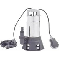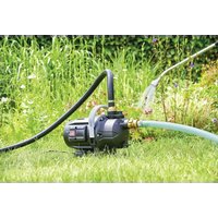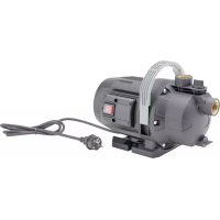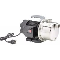
PondoGarden 4500 - Pump Pontec - Free user manual and instructions
Find the device manual for free PondoGarden 4500 Pontec in PDF.


User questions about PondoGarden 4500 Pontec
0 question about this device. Answer the ones you know or ask your own.
Ask a new question about this device
Download the instructions for your Pump in PDF format for free! Find your manual PondoGarden 4500 - Pontec and take your electronic device back in hand. On this page are published all the documents necessary for the use of your device. PondoGarden 4500 by Pontec.
USER MANUAL PondoGarden 4500 Pontec
EN Operating instructions
FR Notice d'emploi
natural_image
Technical line drawing of two electric motors connected to coiled cables (no text or symbols)A
PondoGarden 3200/3800
text_image
1 2 3 4 5 6 7 8 9 10PondoGarden 4500
text_image
Technical diagram of an electric motor with numbered components for identificationPGN0001
B
natural_image
Technical line drawing of an electric motor with attached hoses and connectors (no text or symbols)GPP0004
C

text_image
Technical diagram of a pump assembly with numbered components and directional arrows indicating motion or adjustment.GPP0005
D
natural_image
Technical line drawing of an electric motor connected to a coiled cable, with no visible text or symbols.GPP0006
Original manual. This manual belongs with the unit and must always be passed on together with the unit.
WARNING
▶ Disconnect all electrical devices in the water from the power supply before reaching into the water. Otherwise there is a risk of severe injuries or death by electrocution.
This unit can be used by children aged 8 and above and by persons with reduced physical, sensory or mental capabilities or lack of experience and knowledge if they are supervised or have been instructed on how to use the unit in a safe way and they understand the hazards involved. Do not allow children to play with the unit. Only allow children to carry out cleaning and user maintenance under supervision.
Safety information
Electrical connection
- Special regulations apply for electrical installation in outdoor spaces. Only a qualified electrician may perform the electrical installation.
- The qualified electrician has the necessary professional training, knowledge and experience to perform electrical installation in outdoor spaces. The electrician can detect potential dangers and knows how to adhere to regional and national standards, regulations and directives.
- For your own safety, please consult a qualified electrician.
- Only connect the unit if the electrical data of the unit and the power supply match.
- Only plug the unit into a correctly installed outlet. Ensure that the unit is fused for a rated fault current of max. 30 mA by means of a fault current protection device.
- Extension cables and power distributors (e.g. outlet strips) must be suitable for outdoor use (splash-proof).
- Protect the plug connection from moisture.
- Only plug the unit into a correctly installed outlet. Ensure that the unit is fused for a rated fault current of max. 30 mA by means of a fault current protection device.
Safe operation
- Never operate the unit if the housing is defective!
- Never operate the unit if an electrical cable is defective!
- A damaged connection cable cannot be replaced. Dispose of the unit.
- Do not carry or pull the unit by its power cable.
- Route lines in such a way that they are protected from damage and do not present a tripping hazard.
• Always unplug the unit before working on it. - Never carry out technical changes to the unit.
- Only carry out work on the unit that is described in this manual.
- Only use original spare parts and accessories.
Product Description
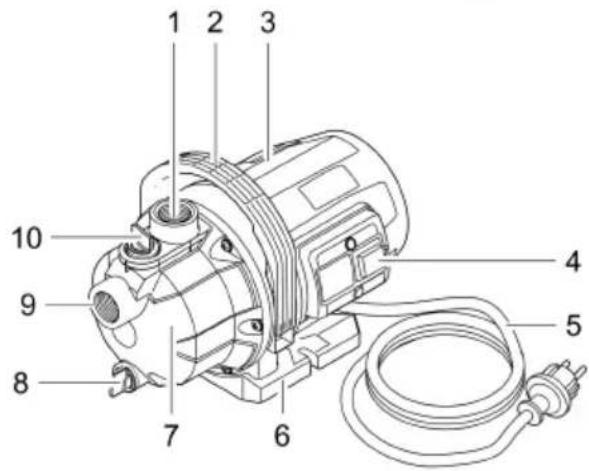
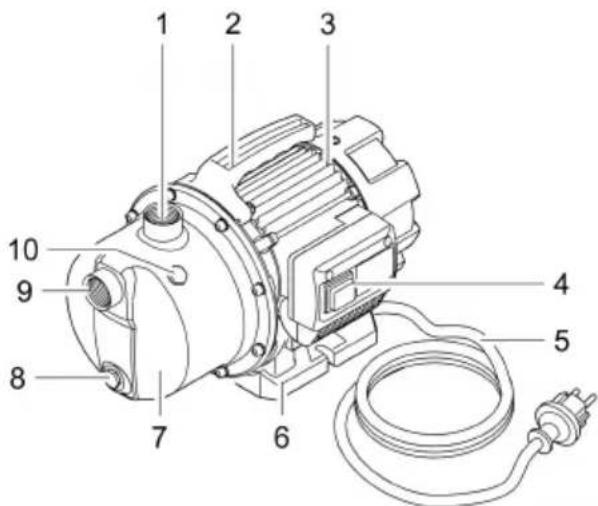
Overview
| ☐ A | Description |
| 1 | Pressure side connection, G1, female thread |
| 2 | Carry handle |
| 3 | Motor housing |
| 4 | ONOFFswitch |
| 5 | Power connection cable |
| 6 | Pump foot |
| 7 | Pump housing |
| 8 | Water drainscrew |
| 9 | Suction side connection, G1, female thread |
| 10 | Water fillingscrew |
The unit contains cast iron, which is subject to a natural corrosion process. This does not impair the function of the unit.
Intended use
Only use the product described in this manual as follows:
- For transferring water from and draining basins or ponds/pools.
- For irrigating and watering.
- For pumping clear water or rain water.
• Extraction of water from a well. - Only for irrigation and watering purposes!
- For pumping the water out of water butts/rain barrels or cisterns.
- Operate the product in compliance with the technical data. (→ Technical data)
Possible incorrect use
The following restrictions apply to the unit:
- Do not use for long-term operation (e.g. continuous recirculation of the water in a pond).
- Not suitable for salt water.
- Never use for pumping dirty water/waste water.
- Do not connect to the drinking water supply.
- Not suitable for drinking water.
- Do not use for commercial or industrial purposes.
- Do not use in conjunction with chemicals, foodstuff, easily flammable or explosive substances.
Installation and connection
To reduce pump noise, connect the pump to the pipework via flexible, pressure-resistant hose lines for fixed installation.
Equip the suction line with a pre-filter and a non-return or foot valve. In addition, fasten the suction hose (e.g. tying it to a stake) to take its weight off the pump.
• Install the pump in a horizontal and stable position in a dry place.
- For permanent installation of the pump, ensure that a sufficiently large collecting basin can be positioned underneath the discharge screw for emptying the pump.
- If possible, install the pump in a higher position than the container/reservoir from which the water is to be pumped. If this is not possible, a pressure-proof valve must be fitted between the pump and the suction hose.
- Only use vacuum-proof pressure hoses on the pressure and suction side.
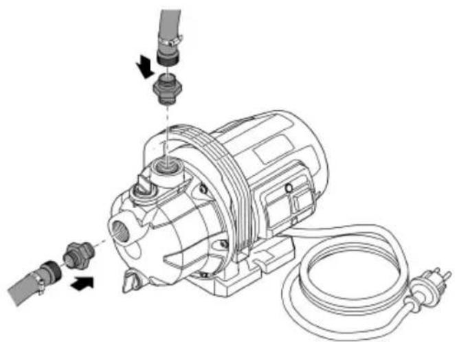
□ B
- Screw the suction hose and the pressure hose together with the hose connector, hose clip and fitting onto the suction side (G1) or pressure side (G1) respectively.
Operation
CAUTION
Risk of burns due to hot water. Water in the pump may be heated to a high temperature in the event of defective electronics or lack of water supply on the suction side.
▶ Disconnect the power plug before carrying out any work on the unit.
▶ Allow the water in the pump to cool down.
Start-up of the device
It is necessary to fill the pump and expel the air from the suction line before using. It can take several minutes to expel air from the suction line.
How to proceed:
□ C
- Unscrew the water infill screw.
- Pour water into the infill opening until it overflows.
- Screw in the water infill screw again.
- Open the pressure line if necessary.
- Insert the power plug into the socket.
- Switch on the pump.
- The pump starts pumping immediately. The emerging water still contains some air.
Shutting down the pump
How to proceed:
- Switch off the pump
- Disconnect the power plug.
- Depressurise the pressure line by opening the water withdrawal points.
- Also open any non-return valves fitted in the suction line.
- When the pump is switched off, residual water in the hose may flow back and out of the pump intake.
If the pump is to be completely removed:
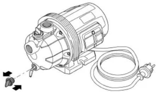
□D
- Remove the connected hoses on the pressure and suction side.
- Undo the water drain screw and tip the pump to allow the residual water to drain out.
- Screw in the water drain screw again.
- Check that the seal is in place and correctly functioning.
Storage/winter protection
The unit is not frost-proof and has to be removed and put into storage if minus temperatures are expected. How to correctly store the unit:
- Drain the water remaining in the unit, in the hoses, pipe and connections as much as possible.
- Thoroughly clean the unit and renew any damaged parts.
- Store the unit in a dry and frost-free place.
- Protect open plug connections from moisture and dirt.
Malfunction remedy
| Malfunction | Cause | Remedy |
| Pump does not start. | The pump is switched off. | Switch on the pump. |
| Power supply interrupted | Check the electrical plug connections. | |
| Pump switches off after operating briefly | Overload protection has switched the pump off due to overheating. | Clean the connection on the suction side and the suction line.Allow the pump to cool down. |
| Blockage on the suction side | Clean the intake and suction line. | |
| The pump is not delivering, or the delivered quantity is insufficient. | The pump is not sufficiently filled with water. | Fill the pump and ensure that the water does not flow out on the pressure side. |
| Pressure line blocked | Open the water withdrawal point on the pressure side.Route the pressure hose without kinks. | |
| Suction line blocked | Clean the connection on the suction side and the suction line.Route the suction hose without kinks | |
| Leak on the suction side | Eliminate leak on the suction side | |
| External pre-filter (optional) clogged | Clean the pre-filter |
Technical data
| Description | GP 3200 | GP 3800 | GP 4500 | ||
| Rated voltage | V AC | 230 | 230 | 230 | |
| Rated frequency | Hz | 50 | 50 | 50 | |
| Power consumption | W | 500 | 650 | 900 | |
| Protection type | IPX4 | IPX4 | IPX4 | ||
| Max. continuous sound pressure level | db (A) | 63 | 68 | 68 | |
| Connection, suction/pressure side | G1 | G1 | G1 | ||
| Max. water pressure, pressure side | bar | 3.5 | 4.0 | 4.5 | |
| Max. pump capacity | l/h | 3200 | 3600 | 4200 | |
| Max. pump head | m | 35 | 40 | 45 | |
| Max. permissible grain size of particles in the water | mm | 2 | 2 | 2 | |
| Cable length | m | 1.5 | 1.5 | 1.5 | |
| Max. permissible ambient temperature | °C | +35 | +35 | +35 | |
| Dimensions | Length | mm | 350 | 350 | 370 |
| Width | mm | 210 | 210 | 230 | |
| Height | mm | 200 | 200 | 210 | |
| Weight | kg | 5.4 | 6.2 | 8.2? | |
Symbols on the unit
| IP X4 | The unit is protected against the ingress of splash water. |
| Do not dispose of the unit with normal household waste. | |
| Read the operating instructions. |
Disposal
NOTE

Do not dispose of this unit with household waste.
▶ Dispose of the unit by using the return system provided for this purpose.
▶ Render the unit unusable by cutting the cables.
Guarantee conditions
PfG grants a 2 year guarantee from the date of sale on proven material and manufacturing faults. Wear parts such as bulbs etc. are exempted from the guarantee. Prerequisite for our guarantee is the presentation of the purchase receipt. Our guarantee will become null and void if the unit is misused, electrically or mechanically damaged by inappropriate use and improper repair by non-authorised workshops. Repairs are reserved for workshops authorised by PfG or by PfG itself. In the case of warranty claims, please return the defective unit or part freight paid to PfG together with a description of the fault and the purchase receipt. PfG reserves the right to invoice repair costs. PfG is not liable for transport damage. Any damage must be claimed against the carrier. Further claims of whatever type, especially consequential damage, are excluded. This guarantee does not affect the final customer's claims against the dealer.
text_image
Technical diagram of an electric motor with labeled parts including pump, motor, and wiringPGN0003