PondoMax Eco 8500 C - Pump Pontec - Free user manual and instructions
Find the device manual for free PondoMax Eco 8500 C Pontec in PDF.
Questions des utilisateurs sur PondoMax Eco 8500 C Pontec
0 question sur cet appareil. Repondez a celles que vous connaissez ou posez la votre.
Poser une nouvelle question sur cet appareil
Download the instructions for your Pump in PDF format for free! Find your manual PondoMax Eco 8500 C - Pontec and take your electronic device back in hand. On this page are published all the documents necessary for the use of your device. PondoMax Eco 8500 C by Pontec.
USER MANUAL PondoMax Eco 8500 C Pontec
- EN - Translation of the original Operating Instructions
WARNING WARNING This unit can be used by children aged 8 and above and by per- sons with reduced physical, sensory or mental capabilities or lack of experience and knowledge if they are supervised or have been instructed on how to use the unit in a safe way and they understand the hazards involved. Do not allow children to play with the unit. Only allow children to carry out cleaning and user maintenance un- der supervision. Ensure that the unit is fused for a rated fault current of max. 30 mA by means of a fault current protection device. Only connect the unit if the electrical data of the unit and the power supply correspond. The unit data is to be found on the unit type plate, on the packaging or in this manual. Possible death or severe injury from electrocution! Before reaching into the water, disconnect all electrical units in the water from the mains. Only operate the unit if no persons are in the water. Do not use the unit if electrical cables or housings are damaged. A damaged connection cable cannot be replaced. Dispose of the unit.- EN -
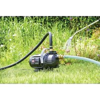
Information about these operating instructions You made a good choice with the purchase of this product PondoMax Eco 8500 C / 11500 C / 17500 C. Prior to commissioning the unit, please read the instructions of use carefully and fully familiarise yourself with the unit. Ensure that all work on and with this unit is only carried out in accordance with these instructions. Adhere to the safety information for the correct and safe use of the unit. Keep these instructions in a safe place! Please also hand over the instructions when passing the unit on to a new owner. Safety information Correct electrical installation Electrical installations must meet the national regulations and may only be carried out by a qualified electrician. A person is regarded as a qualified electrician if, due to his/her vocational education, knowledge and experience, he or she is capable of and authorised to judge and carry out the work commissioned to him/her. This also includes the recognition of possible hazards and the adherence to the pertinent regional and national standards, rules and regula- tions. For your own safety, please consult a qualified electrician. Extension cables and power distributors (e.g. outlet strips) must be suitable for outdoor use (splash-proof). Protect the plug connection from moisture. Only connect the unit to a correctly fitted socket. Safe operation The impeller unit in the pump contains a magnet with a strong magnetic field that may affect the operation of pace- makers or implantable cardioverter defibrillators (ICDs). Always keep magnets at least 0.2 m away from implanted devices. Never carry or pull the unit by the electrical cable. Route cables such that they are protected from damage and do not present a tripping hazard. Never carry out technical changes to the unit. Only carry out work on the unit that is described in this manual. If problems cannot be overcome, please contact an authorised customer service point or, if in doubt, the manufacturer. Only use original spare parts and accessories for the unit. Product Description Overview
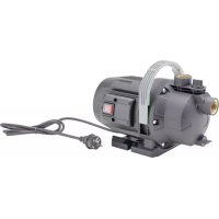
Filter housing with filter pump
Controller for regulating the filter pump power 3 Stepped hose adapter with union nut Intended use Only use the product described in this manual as follows: For pumping normal pond water for filter systems, waterfall systems and water course systems. Operate in accordance with instructions. The following restrictions apply to the unit: Do not use in swimming ponds. Never use the unit with fluids other than water. Never run the unit without water. Do not use in conjunction with chemicals, foodstuff, easily flammable or explosive substances. Do not use for commercial or industrial purposes. Do not connect to the domestic water supply.- EN -
Installation and connection
W A R N I N G Severe injuries or death due to operation of this unit in a swimming pond. Defective electrical components will electrify the water with dangerous electrical voltage. Never use the unit in bodies of water that can be entered (swimming ponds, swimming pools, etc.). Install the controller with a distance of at least 2 m from the water. Install electrical components (sockets, cables, etc.) with a voltage of U > 12 V AC or U > 30 V DC at a dis- tance of at least 2 m from the water. Submerged installation of the pump Only install the unit below water level. Place the unit horizontally on the ground ensuring its stable position. Protect the controller from direct sunlight. How to proceed:
1. Shorten the stepped hose adapter to the diameter of the hose used if necessary.
– This reduces pressure losses.
2. Screw the stepped hose adapter including the union nut to the outlet.
– Align the stepped hose adapter prior to tightening the union nut.
3. Slip the hose clip over the hose, fit the hose onto the hose connector and secure with the hose clip.
Dry installation of the pump
Swimming pond or pool that may be accessed by people. – Install the unit at least 2 m away from the water. Protect the pump from direct sunlight. Protect the controller from direct sunlight. How to proceed:
– The screws are used as transport protection and not required for operation.
2. Actuate the engagement hook and fold up the strainer top casing. Then remove the pump.
3. Shorten the stepped hose adapter to the diameter of the hose used if necessary.
– This reduces pressure losses.
4. Screw the stepped hose adapter including sealing ring onto the inlet.
5. Slip the hose clip over the hose, fit the hose onto the hose connector and secure with the hose clip.
6. Screw the stepped hose adapter including union nut and sealing ring to the outlet.
7. Slip the hose clip over the hose, fit the hose onto the hose connector and secure with the hose clip.
Mounting the controller to the wall How to proceed:
1. Screw a suitable screw into the wall.
2. Position the controller on the screw.
– Ensure that the head of the screw is positioned in the hanger on the rear of the controller.- EN -
Commissioning/start-up N O T E The unit will be destroyed if it is operated with a dimmer. It contains sensitive electrical components. Do not connect the unit to a dimmable power supply. Switching on First connect the controller to the mains supply, then switch on the pump at the controller. Switching off Switch the pump off at the controller. Disconnect the controller from the mains before performing any work on the unit. Operation Controller overview PMX0019 Description Function 1 Four-digit display
Display of power in percent (%) or watt (W)
Display of the error code in the event of an error
“On/Off” button For switching the pump on or off
Arrow keys Increase or decrease power
Operating functions Switching the pump on/off Proceed as follows Information Press the button briefly to turn the pump on or off. When the pump is switched off, the display shows "OFF". Increasing/decreasing power Proceed as follows Information Press the desired button several times or press and hold it to change the power. When a button is pressed, the display automatically shows the power values in percent(%). Adjustable range: 1 % … 100 % Increment: 1 % The adjusted value is immediately adopted. After 15 s without operation, the controller automatically switches to the "W” display. Displaying the current power value Proceed as follows Information Briefly press the button to toggle the display. Display "W" Shows the current pump power value in watt Tolerance: ±5 % of the max. power consumption. Display "%" Shows the current pump power value as a percentage. Display range: 1 to 100 After 15 s without operation, the controller automatically switches to the "W” display. Malfunction remedy Troubleshooting overview Malfunction Cause Remedy Pump does not start No mains voltage Check the mains voltage.
Check supply lines. Pump not switched on Switch the pump on at the controller Pump does not transport fluid Filter housing clogged Clean strainer casings Excessively soiled water Clean the pump. The pump automatically switches on again once the motor has cooled down. Pump is set too low Increase the rotation speed of the pump at the controller The impeller unit is blocked Disconnect the power supply and remove obstacle. Then switch the pump on again. Insufficient delivered quan- tity Filter housing clogged Clean strainer casings Excessive loss in the supply lines Select larger hose diameter Adjust stepped hose adapter to hose diameter Reduce hose length to minimum necessary
Avoid unnecessary connection elements Pump is set too low Increase the rotation speed of the pump at the controller Pump switches off after op- erating briefly Excessively soiled water Clean the pump. The pump automatically switches on again once the motor has cooled down. The impeller unit is blocked Disconnect the power supply and remove obstacle. Then switch the pump on again. Pump has run dry. Flood the pump. Fully submerge the pump for operation in the pond.- EN -
Error messages The error message automatically disappears after the error has been corrected. Error message Cause Remedy Er1 Missing connection to pump, cable break Pull power plug, wait for approx. 10 s. Then switch the pump on again. If the error message is still displayed, there is a cable break. Take the pump to a specialist retailer for repair or send it to PfG. Er3 Excess temperature Check that impeller unit moves freely If the impeller unit is sluggish, the pump is requiring too much power
The ambient temperature i s too high Er4 Overcurrent Check that impeller unit moves freely
If the impeller unit is sluggish, the pump is requiring too much power Er5 Pump blocked Check pump and remove obstacle Er6 Pump has run dry Submerge pump in water
For dry installation ensu re adequate water supply Er7 Overvoltage Connect the pump to the correct mains voltage
The unit is not suitable for use with the existing mains voltage range Er8 Undervoltage Keep extension cable to the pump as short as possible. The voltage to the pump is too low due to the voltage drop in long cables. Use extension cable to the pump with greater conductor cross-section The voltage to the pump is too low due to the voltage drop in cables with too small of a conductor cross
section. Maintenance and cleaning Cleaning the device T I P Recommendation regarding cleaning: Clean the unit as required but at least twice a year. When cleaning the pump, pay particular attention to the cleaning of the impeller unit and pump housing. In the event of the filter housing capacity reducing, clean the unit under running water using a brush. Do not not use cleaning agents or chemical solutions. Recommended cleaning agent for removing stubborn limescale deposits: – Vinegar- and chlorine-free household cleaning agent. After cleaning, thoroughly rinse all parts in clean water. Cleaning/replacing the impeller unit How to proceed:
– The screws are used as transport protection and not required for operation.
2. Actuate the engagement hook and fold up the strainer top casing.
5. Remove the pump housing including its holding ring, sealing and impeller unit.
– Clean all components under running water using a soft brush, replace damage parts.
6. Reassemble the unit in the reverse order.
– Place the pump cable into the cable opening of the bottom strainer casing such that the cable will not be crushed when closing the filter housing.- EN -
Storage/winter protection The unit is not frost-proof and has to be removed and put into storage if minus temperatures are expected. How to correctly store the unit: Thoroughly clean the unit, check it for damage and replace any damaged parts. Protect electrical connections from moisture and dirt. Store the pump submerged and in a frost-free environment. Protect open plug connections from moisture and dirt. Wear parts Impeller unit Disposal N O T E Do not dispose of this unit with domestic waste. Render the unit unusable beforehand by cutting the cables and dispose of the unit via the return system provided for this purpose. Guarantee conditions PfG grants a 3 year guarantee from the date of sale on proven material and manufacturing faults. Wear parts such as bulbs etc. are exempted from the guarantee. Prerequisite for our guarantee is the presentation of the purchase receipt. Our guarantee will become null and void if the unit is misused, electrically or mechanically damaged by inappropriate use and improper repair by non-authorised workshops. Repairs are reserved for workshops authorised by PfG or by PfG itself. In the case of warranty claims, please return the defective unit or part freight paid to PfG together with a de- scription of the fault and the purchase receipt. PfG reserves the right to invoice repair costs. PfG is not liable for transport damage. Any damage must be claimed against the carrier. Further claims of whatever type, especially conse- quential damage, are excluded. This guarantee does not affect the final customer’s claims against the dealer.- FR -
Toets "Aan/uit" Pomp in
slange. – Dermed reduceres tryktab.
slange. – Dermed reduceres tryktab.