
SAB00102 - Door sensor HARVIA - Free user manual and instructions
Find the device manual for free SAB00102 HARVIA in PDF.
| Product type | Door sensor for sauna |
| Brand | Harvia |
| Model | SAB00102 |
| Control unit dimensions | 85 x 85 x 40 mm |
| Push button dimensions | 55 x 55 x 15 mm |
| Button installation opening diameter | 50 mm |
| Door sensor dimensions | ∅ 6 x 28 mm |
| Sensor bracket dimensions | 20 x 15 x 10 mm |
| Magnet dimensions | ∅ 10 x 3 mm |
| Magnet bracket dimensions | 18 x 12 x 15 mm |
| Operating voltage | 230 V AC, 50/60 Hz |
| Protection degree | IP X4 |
| Ambient operating temperature | -40 °C to +40 °C |
| Sensor operating temperature | -20 °C to 85 °C |
| Switching distance | 10 cm (contact opening) |
| Sensor cable length | 5 m |
| Button cable length | 4 m |
| Connection cable cross-section | Power: 3 x 1.5 mm²; Signal: 2 x 0.5 mm² |
| Delivery contents | Control unit, illuminated button, door sensor, sensor bracket, magnet, magnet bracket, mounting materials, instructions |
| Main functions | Door monitoring for remote start; cancellation of start if door open |
| Compatibility with sauna controls | Pro series, home.com4, wave.com4 11 kW, Xenio, Xafir |
| Maintenance and cleaning | No maintenance necessary |
| Safety | Installation by qualified electrician; proper use; do not expose to excessive humidity |
| Spare parts and repairability | Parts available from manufacturer; repair by professional |
| General information | Manufactured by Harvia; manual available in multiple languages |
Frequently Asked Questions - SAB00102 HARVIA
User questions about SAB00102 HARVIA
0 question about this device. Answer the ones you know or ask your own.
Ask a new question about this device
Download the instructions for your Door sensor in PDF format for free! Find your manual SAB00102 - HARVIA and take your electronic device back in hand. On this page are published all the documents necessary for the use of your device. SAB00102 by HARVIA.
USER MANUAL SAB00102 HARVIA
INSTRUCTIONS FOR INSTALLATION AND USE English
natural_image
Technical line drawing of an electronic device housing with a circular component and two cylindrical pins (no text or symbols)EN
DE
FR
IT
NL
CS
PL
PT
SV
FI
RU
Table of Contents
1. About this instruction manual 3
2. Important information for your safety 4
2.1. Intended use 4
2.2. Safety information for the installer 4.
2.3. Safety information for the user 5
3. Product description 6
3.1. Scope of delivery 6
3.2. Product features 6
4. Installation 6
4.1. Installing the power supply unit 6
4.2. Installing the button 7
4.3. Mounting the door sensor .8
4.4. Mounting the magnet .8....
5. Electrical connection 9
6. Connection diagram 10
6.1. Connection to Pro series (Pro B2/3, Pro C2/3, Pro D) 10
6.2. Connection to home.com4 11
6.3. Connection to wave.com4 11kW .11
6.4. Connection to Xenio (CX110C, CX170) 12
6.5. Connection to Xafir (CS110C, CS170) 12
7. Operation 13
8. Maintenance 13
9. Disposal 13
10. Technical data 14
1. About this instruction manual
Read these instructions for installation and use carefully and keep them within reach of the device. This ensures that you can refer to information on safety and operation at any time.
These installation and operating instructions can also be found in the downloads section of our website: www.sentiotec.com/downloads.
Symbols used for warning notices
In these instructions for installation and use, a warning notice located next to an activity indicates that this activity poses a risk. Always observe the warning notices. This prevents damage to property and injuries, which in the worst case may be fatal.
The warning notices contain keywords, which have the following meanings:
DANGER!
Serious or fatal injury will occur if this warning notice is not observed.

WARNING!
Serious or fatal injury can occur if this warning notice is not observed.
CAUTION!
Minor injuries can occur if this warning notice is not observed.
ATTENTION!
This keyword is a warning that damage to property can occur.
Other symbols
This symbol indicates tips and useful information.
Read the operating instructions
2. Important information for your safety
The door sensor system has been manufactured according to the applicable safety regulations. However, hazards may arise during use. Therefore adhere to the following safety information and the specific warning notices in the individual chapters.
2.1. Intended use
The door sensor system monitors the sauna door when using the remote operation function.
A sauna heater controlled by the remote start function of the sauna control unit must pass the combustion test as specified in EN 60335-2-53 paragraph 19.101. If the heater does not meet this requirement, an appropriate safety precaution must be used (for example: safety switch-off or door monitoring)
Any use exceeding this scope is considered improper use. Improper use can result in damage to the product, severe injuries or death.
2.2. Safety information for the installer
- Installation may only be performed by a qualified electrician or similarly qualified person.
- Installation and connection of the door monitoring system may only be performed when the power supply is disconnected.
- Observe the installation instructions for the sauna control unit used.
- Also comply with the regulations applicable at the installation location.
- For your own safety, consult your supplier in the event of problems that are not explained in sufficient detail in the installation instructions.
2.3. Safety information for the user
- The door sensor system must not be used by children under 8 years of age.
- The door sensor system may only be used by children over 8 years of age, by persons with limited psychological, sensory or mental capabilities or by persons with lack of experience/knowledge under the following conditions:
– They are supervised.
– They have been shown how to use the device safely and are aware of the hazards that could occur.
- Children may not play with the door monitoring system.
- Observe the operating instructions for the sauna control unit used.
- For your own safety, consult your supplier in the event of problems that are not described in sufficient detail in the user instructions.
3. Product description
3.1. Scope of delivery
• Door monitoring control unit
- Illuminated button with connection cable
- Door sensor with connection cable
- Door sensor holder
- Magnet
- Magnet holder
• Installation material
- Assembly instructions
3.2. Product features
The door monitoring system monitors the closed sauna door when the remote start is activated. If the sauna door is opened during “Standby for remote control”, the remote start function is cancelled.
Compatible sauna control units:
Pro series, home.com4, wave.com4 11 kW, Xenio, Xafir
4. Installation
During installation observe the technical data on Page 14:
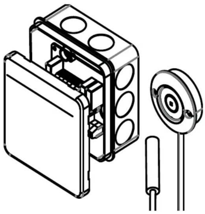
4.1. Installing the power supply unit
- Fasten the power supply unit 1 of the door monitoring system near the sauna control using the screws provided (power supply unit - for 2-part control units)
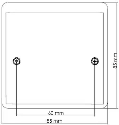
Fig. A: Example installation
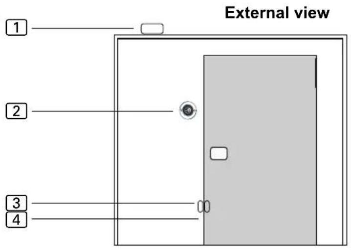
1 Control unit
2 Button
3 Door sensor
4 Magnet
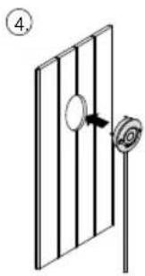
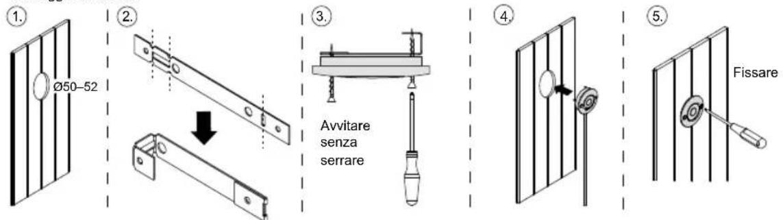
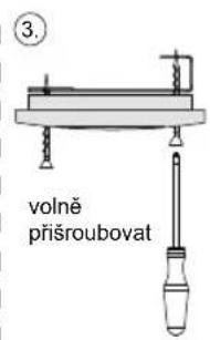
4.2. Installing the button
The button ② can be installed on the surface or flush-mounted (Fig. B).
Flush mounted / flush mounting
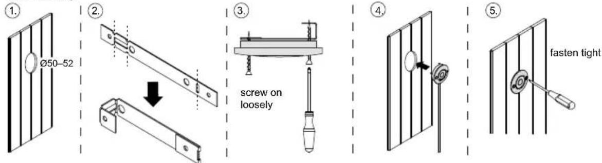
Fig. B
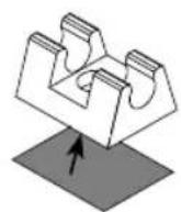
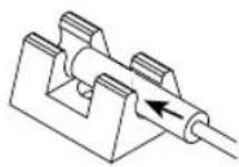
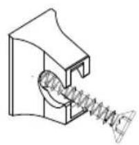
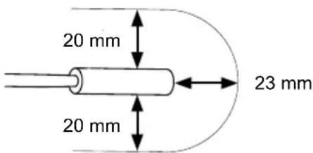
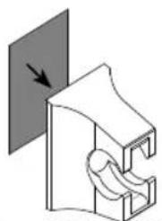
4.3. Mounting the door sensor
Mount the door sensor near of the sauna door, taking account of the technical data on Page 14.
The door sensor set must be mounted so that contact with the door sensor is interrupted if the door is open by more than 10 cm.
- For a wooden sauna cabin:
▶ Use the wood screws supplied (Fig. C).
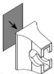
- For a glass surface:
▶ Use the double-sided adhesive tape (Fig. D).
▶ Drill a hole 8 mm in diameter and insert the rubber seal.
Then insert the door sensor (Fig. E or F)
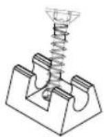
Fig. C Fig. D
natural_image
Pure technical line drawing of a mechanical component with no text or symbolsFig. E Fig. F
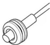
4.4. Mounting the magnet
Make sure the distance to the door sensor is correct so that it works properly.
Attach the magnet to the sauna door with the magnet holder:
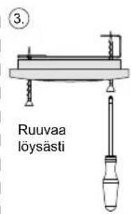
- On a wooden door:
▶ Use the wood screws supplied (Fig. G).
- For a glass door:
▶ Use the double-sided adhesive tape (Fig. H).
Finally, insert the magnet into the holder (Fig. I)
natural_image
Technical line drawing of a mechanical spring assembly (no text or symbols)
natural_image
Diagram of a mechanical component with a curved structure and directional arrow (no text or symbols)
Fig. HFig. G Fig. I
5. Electrical connection
Observe the following points when connecting the power to the door monitoring system:
- Guide the connection cables through the cable bushings. Drill the holes as small as possible (e.g. 2 mm flat blade screwdriver) to maintain the humidity protection.
- Observe the installation instructions for the sauna control unit used. Jumpers may have to be placed and functions enabled in the technician menu.

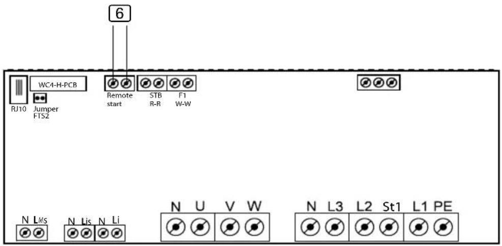
6. Connection diagram
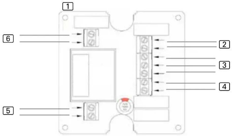
① Power supply unit
2 Door sensor
3 Button (red = LED+, white = SW3, blue = SW4)
4 Remote start switch / remote start system
5 Power supply 230 V\~ 50 / 60 Hz
6 Sauna control unit remote start contacts (polarity not relevant)
6.1. Connection to Pro series (Pro B2/3, Pro C2/3, Pro D)
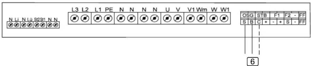
6 Connection to S/B....Remote start of sauna operation / user program 1 Connection to C/B....Remote start of combination mode / user program 2
6.2. Connection to home.com4
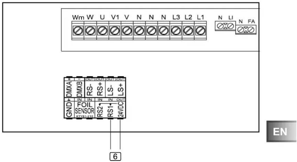
6 Connection to RS1/24 VDC....Remote start
- Make the setting in the technician menu under menu item Mode RS1.
6.3. Connection to wave.com4 11 kW
6 Connection to remote start
6.4. Connection to Xenio (CX110C, CX170)
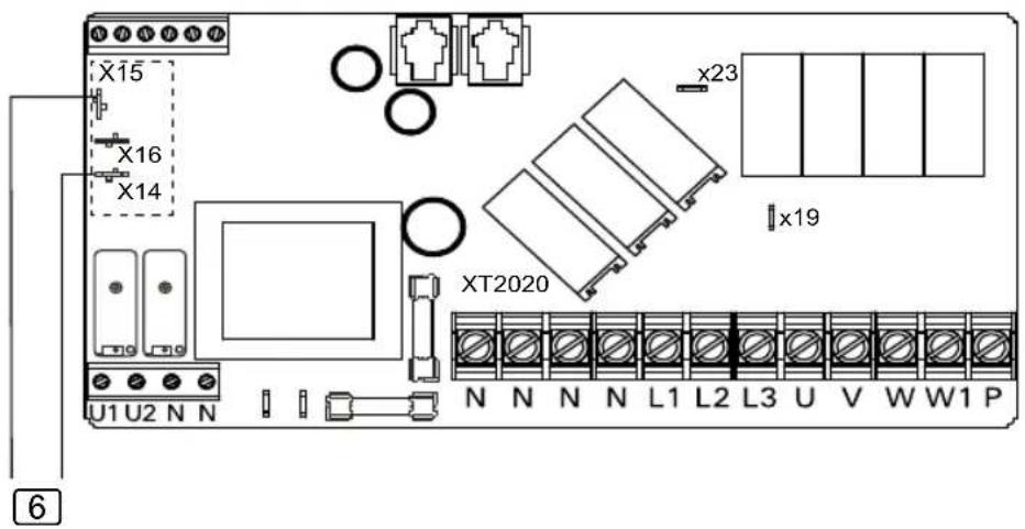
• PIN X15 and X16 must be bridged.
- The SAFE function must be set to ON in the settings.
6.5. Connection to Xafir (CS110C, CS170)
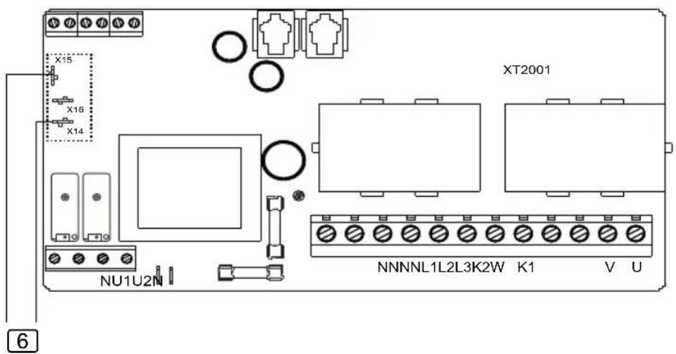
• PIN X15 and X16 must be bridged.
- The SAFE function must be set to ON in the settings.
7. Operation
Observe the operating instructions for the sauna control unit used.
- Make sure that no flammable objects have been placed on the sauna heater.
- Close the sauna door.
- Switch the sauna control unit to remote start in the desired operating mode. Observe the operating instructions for the sauna control unit used.
▶ The activated remote start is displayed.
- Activate the door monitoring button.
▶ The sauna control unit is then ready to be started and stopped using a remote start signal.

If the sauna door is opened when remote start is activated, the remote start function is deactivated.
8. Maintenance
The device is maintenance-free.
9. Disposal
- Dispose of packaging materials in accordance with the applicable waste disposal regulations.
- Used devices contain reusable materials as well as hazardous substances. Therefore, do not dispose of your used device with household waste, but do so in accordance with the locally applicable regulations.
10. Technical data
Ambient conditions
Ambient temperature: -40 °C to +40 °C
Protection class (protected against splashing water): IP X4
Control unit
Dimensions: 85 × 85 × 40 mm
Operating voltage: 230 V 50/60 Hz AC
Illuminated button
Dimensions: 55 × 55 × 15 mm
Diameter of installation opening: 50 mm
Connection cable 4 m - 3 x 0.5 mm ^2 , silicone
Door sensor
Dimensions: ∅ 6 × 28 mm
Connection cable: 5 m - 2 x 0.22 mm ^4
Operating temperature: -20 to 85 °C
Switching distance
Door sensor holder
Dimensions: 20 × 15 × 10 mm
Magnet
Dimensions: ∅ 10 × 3 mm
Magnet holder
Dimensions: 18 × 12 × 15 mm
Connection cables
Power supply: 3 × 1.5 mm^2
Remote start switch or remote start system: 2 × 0.5 mm^2
Remote start signal from sauna control unit: 2 × 0.5 mm^2
Türsensor-System
1-052-722 / SAB00102
natural_image
Technical line drawing of an electronic device with internal components and a circular component (no text or symbols)Inhaltsverzeichnis
natural_image
Technical illustration of a mechanical bracket assembly with an arrow indicating a transformation (no text or symbols present)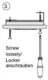
natural_image
Simple line drawing of a door with a knob and a scroll, no text or symbols present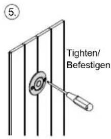
Abb. B
4.3. Montage Türsensor
natural_image
Pure technical line drawing of a mechanical component with no text or symbolsnatural_image
Technical line drawing of a mechanical spring assembly (no text or symbols)
natural_image
Pure mechanical diagram showing a clamping mechanism with a downward arrow, no text or symbols present
Abb. HAbb. G Abb. I
natural_image
Technical line drawing of an electronic device with internal components and a circular component (no text or symbols)FR
Table des matières
1. Concernant ces instructions 3
natural_image
Technical diagram showing two mechanical components with a downward arrow indicating assembly or transformation (no text or symbols present)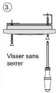

natural_image
Simple line drawing of a door with a knob and a scroll, no text or symbols present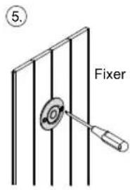
Fig. B
natural_image
Pure mechanical component diagram without any text, numbers, or symbolsnatural_image
Technical line drawing of a mechanical spring assembly (no text or symbols)
natural_image
Diagram of a mechanical component with a curved structure and directional arrow (no text or symbols)
Fig. HFig. G Fig. I
natural_image
Technical line drawing of an electronic device with internal components and a circular component (no text or symbols)IT
Indice
Flush mounted / Montaggio a incasso
natural_image
Pure mechanical component diagram without any text, numbers, or symbolsFig. E Fig. F
natural_image
Technical line drawing of a mechanical spring assembly (no text or symbols)
natural_image
Diagram of a mechanical component with a curved structure and directional arrow (no text or symbols)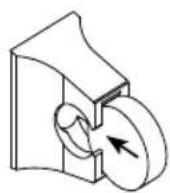
Fig. HFig. G Fig. I
natural_image
Technical line drawing of an electronic device with internal components and a circular component (no text or symbols)NL
Inhoudsopgave
natural_image
Technical diagram showing two mechanical bracket assemblies with a downward arrow indicating assembly (no text or symbols present)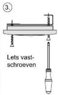

natural_image
Simple line drawing of a door with a knob and a rose, no text or symbols present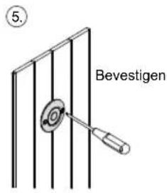

Afb. B
4.3. Montage deursensor
natural_image
Pure mechanical component diagram without any text, numbers, or symbolsnatural_image
Technical line drawing of a mechanical spring assembly (no text or symbols)Afb. HAfb. G Afb. I
natural_image
Pure mechanical component diagram without any text, numbers, or symbols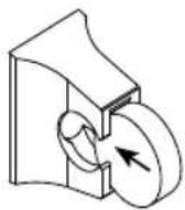
natural_image
Technical line drawing of an electronic device with internal components and a circular component (no text or symbols)cs
Obsah
1. O tomto návodu 3
natural_image
Simple line drawing of a door with a knob and a scroll wheel, no text or symbols present

Obr. B
natural_image
Pure technical line drawing of a mechanical component with no text or symbols4.4. Montáž magnetu
natural_image
Technical line drawing of a mechanical spring assembly (no text or symbols)Obr. HObr. G Obr. I
natural_image
Pure mechanical diagram showing a clamping mechanism with no text or symbols
natural_image
Technical line drawing of an electronic device with internal components and a circular component (no text or symbols)PL
Spis treści
natural_image
Technical diagram showing two mechanical bracket assemblies with a downward arrow indicating assembly (no text or symbols present)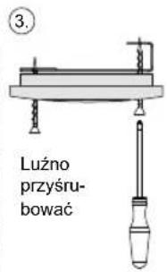
natural_image
Simple line drawing of a door with a knob and a rose, no text or symbols present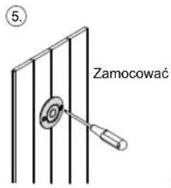
natural_image
Technical line drawing of a mechanical component with concentric rings and shafts (no text or symbols)natural_image
Technical line drawing of a mechanical spring assembly (no text or symbols)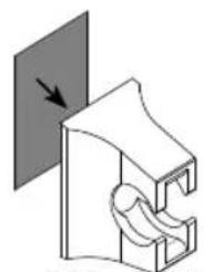
natural_image
Pure mechanical diagram showing a clamping mechanism with no text or symbols
Rys. HRys. G Rys. I
natural_image
Technical line drawing of an electronic device with internal components and a circular component (no text or symbols)PT
Índice
1. Sobre este manual 3
natural_image
Mechanical assembly diagram showing two views of a bracket with mounting holes and a downward arrow indicating motion (no text or symbols)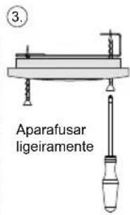

natural_image
Simple line drawing of a door with a knob and a rose, no text or symbols present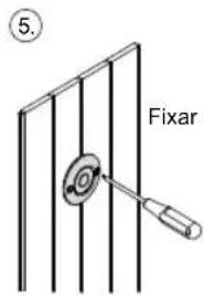
Fig. B

natural_image
Pure mechanical component diagram without any text, numbers, or symbolsFig. E Fig. F
natural_image
Technical line drawing of a mechanical spring assembly (no text or symbols)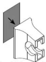
natural_image
Pure mechanical diagram showing a bracket with a curved cutout and an arrow indicating direction (no text or symbols)
Fig. HFig. G Fig. I
5. Ligação elétrica
natural_image
Technical line drawing of an electronic device with internal components and a circular component (no text or symbols)SV
natural_image
Mechanical assembly diagram showing two views of a bracket with mounting holes and a downward arrow indicating transformation (no text or symbols)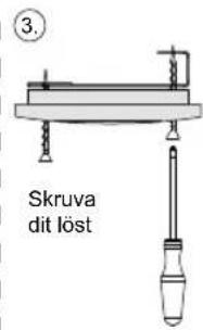

natural_image
Simple line drawing of a door with a knob and a rose, no text or symbols present
Bild B
natural_image
Pure mechanical component diagram without any text, numbers, or symbolsnatural_image
Technical line drawing of a mechanical spring assembly (no text or symbols)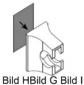
natural_image
Technical line drawing of an electronic device housing with internal components and a circular component (no text or symbols)FI
Sisällys
natural_image
Simple line drawing of a door with a knob and a rose, no text or symbols present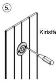
natural_image
Pure technical line drawing of a mechanical component with no text or symbolsnatural_image
Technical line drawing of a mechanical spring assembly (no text or symbols)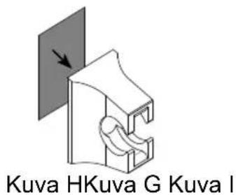
natural_image
Technical line drawing of an electronic device with internal components and a circular component (no text or symbols)RU
Содержание
natural_image
Mechanical assembly diagram showing two views of a bracket with mounting holes and a downward arrow indicating motion (no text or symbols)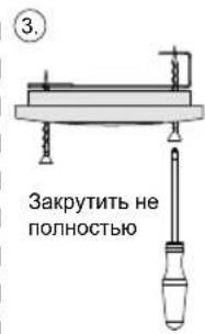
natural_image
Simple line drawing of a door with a knob and a scroll, no text or symbols present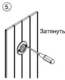
natural_image
Pure mechanical component diagram without any text, numbers, or symbolsnatural_image
Technical line drawing of a mechanical spring assembly (no text or symbols)Рис. НРис. G Рис. I

natural_image
Pure mechanical diagram showing a bracket with a curved cutout and an arrow indicating direction (no text or symbols)
- INSTRUCTIONS FOR INSTALLATION AND USE English
- Table of Contents
- About this instruction manual 3
- Important information for your safety 4
- Product description 6
- Installation 6
- Electrical connection 9
- Connection diagram 10
- Operation 13
- Maintenance 13
- Disposal 13
- Technical data 14
- About this instruction manual
- Symbols used for warning notices
- DANGER!
- WARNING!
- CAUTION!
- ATTENTION!
- Other symbols
- Important information for your safety
- Intended use
- Safety information for the installer
- Safety information for the user
- Product description
- Scope of delivery
- Product features
- Installation
- Installing the power supply unit
- Installing the button
- Mounting the door sensor
- Mounting the magnet
- Electrical connection
- Connection diagram
- Connection to Pro series (Pro B2/3, Pro C2/3, Pro D)
- Connection to home.com4
- Connection to wave.com4 11 kW
- Connection to Xenio (CX110C, CX170)
- Connection to Xafir (CS110C, CS170)
- Operation
- Maintenance
- Disposal
- Technical data
- Ambient conditions
- Control unit
- Illuminated button
- Door sensor
- Door sensor holder
- Magnet
- Magnet holder
- Connection cables
- Türsensor-System
- Inhaltsverzeichnis
- Montage Türsensor
- Table des matières
- Concernant ces instructions 3
- Indice
- Inhoudsopgave
- Montage deursensor
- Obsah
- O tomto návodu 3
- Montáž magnetu
- Spis treści
- Índice
- Sobre este manual 3
- Ligação elétrica
- Sisällys
- Содержание
Brand : HARVIA
Model : SAB00102
Category : Door sensor