
SAB00103 - Door sensor HARVIA - Free user manual and instructions
Find the device manual for free SAB00103 HARVIA in PDF.
| Product type | Door sensor (kit) |
| Brand | Harvia |
| Model | SAB00103 |
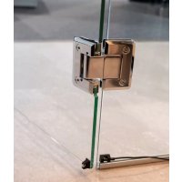
| Use | Monitoring of closed sauna door |
| Sensor dimensions | ∅6 x 28 mm |
| Sensor holder dimensions | 20 x 15 x 10 mm |
| Magnet dimensions | ∅10 x 3 mm |
| Magnet holder dimensions | 18 x 12 x 15 mm |
| Connection cable length | 5 m (2 x 0.22 mm²) |
| Switching distance | 20 mm |
| Service temperature | -20 to 85 °C |
| Power supply | None (dry contact) |
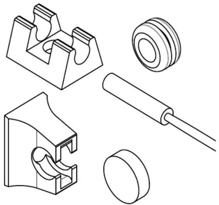
| Delivery contents | Sensor, sensor holder, magnet, magnet holder, mounting hardware, instructions |
| Mounting | On wood (screws), on glass (double-sided adhesive tape), on metal (drilling ∅8 mm with gasket) |
| Electrical connection | Refer to the sauna control manual |
| Maintenance | No maintenance required |
| Safety | Installation by qualified electrician, de-energized, comply with local standards |
| Disposal | Do not dispose of with household waste, follow local regulations |
Frequently Asked Questions - SAB00103 HARVIA
User questions about SAB00103 HARVIA
0 question about this device. Answer the ones you know or ask your own.
Ask a new question about this device
Download the instructions for your Door sensor in PDF format for free! Find your manual SAB00103 - HARVIA and take your electronic device back in hand. On this page are published all the documents necessary for the use of your device. SAB00103 by HARVIA.
USER MANUAL SAB00103 HARVIA
INSTRUCTIONS FOR INSTALLATION AND USE English
natural_image
Technical line drawings of mechanical components including a bracket, gear, roller, and cylindrical parts (no text or labels)Table of Contents
- About this instruction manual 3
- Important information for your safety 3
2.1. Intended use 3
2.2. Safety information for the installer 3.
- Product description 4
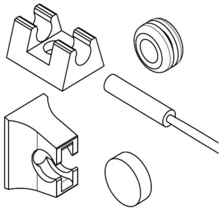
3.1. Scope of delivery 4
3.2. Product features 4
- Installation 4
4.1. Mounting the door sensor 4
4.2. Mounting the magnet 5
- Electrical connection 5
- Maintenance 6
- Disposal 6
- Technical data 6
1. About this instruction manual
Read these installation instructions carefully and keep them within reach when using the device. This ensures that you can refer to information on safety and operation at any time.
These installation and operating instructions can also be found in the downloads section of our website: www.sentiotec.com/downloads.
2. Important information for your safety
Please follow the following safety instructions.
2.1. Intended use
The door sensor set is used to monitor that the sauna door is closed.
2.2. Safety information for the installer
- Installation may only be performed by a qualified electrician or similarly qualified person.
- It may only be installed when the power has been disconnected.
- Observe the installation instructions for the sauna control unit used.
- Also comply with the regulations applicable at the installation location.
- For your own safety, consult your supplier in the event of problems that are not explained in sufficient detail in the installation instructions.
3. Product description
3.1. Scope of delivery
• Door sensor with connection cable
- Door sensor holder
- Magnet
- Magnet holder
• Installation material
• Assembly instructions
3.2. Product features
The door sensor set is used to monitor that the sauna door is closed.
Observe the operating instructions for the sauna control unit used.
4. Installation
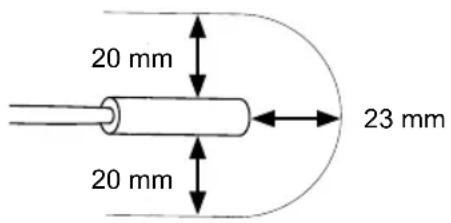
Mount the door sensor near of the sauna door, taking account of the technical data on Page 6.
The door sensor set must be mounted so that contact with the door sensor is interrupted if the door is open by more than 10 cm.
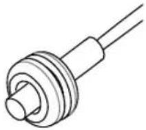
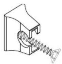
4.1. Mounting the door sensor
- For a wooden sauna cabin:
▶ Use the wood screws supplied (Fig. A). - For a glass surface:
▶ Use the double-sided adhesive tape (Fig. B). - For a metal door frame:
▶ Drill a hole 8 mm in diameter and insert the rubber seal.
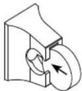
Then insert the door sensor (Fig. C or D)
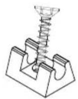
Fig. A Fig. B
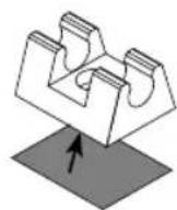
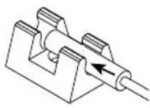
Fig. C Fig. D
natural_image
Pure mechanical component diagram without any text, numbers, or symbols4.2. Mounting the magnet
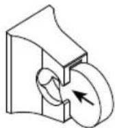
Attach the magnet to the sauna door with the magnet holder:
Make sure the distance to the door sensor is correct so that it works properly.
EN
- On a wooden door:
▶ Use the enclosed wood screw (Fig. E).
- For a glass door:
▶ Use the double-sided adhesive tape (Fig. F).
Finally, insert the magnet into the holder (Fig. G)
natural_image
Technical line drawing of a mechanical spring assembly (no text or symbols)
natural_image
Pure mechanical component diagram without any text, numbers, or symbolsFig. F Fig. E Fig. G

5. Electrical connection
Observe the installation and operating instructions for the sauna control unit used.
6. Maintenance
The device is maintenance-free.
7. Disposal
- Dispose of packaging materials in accordance with the applicable waste disposal regulations.
- Used devices contain reusable materials as well as hazardous substances. Therefore, do not dispose of your used device with household waste, but do so in accordance with the locally applicable regulations.
8. Technical data
Door sensor
Dimensions: ∅ 6 × 28 mm
Connection cable: 5 m - 2 x 0.22 mm 4
Operating temperature: -20 to 85°C
Switching distance:
Door sensor holder
Dimensions: 20 × 15 × 10 mm
Magnet
Dimensions: ∅ 10 × 3 mm
Magnet holder
Dimensions: 18 × 12 × 15 mm
Türsensor-Set
1-052-723 / SAB00103
MONTAGEANWEISUNG
Deutsch
DE
natural_image
Technical line drawings of mechanical components including a bracket, washer, roller, and cylindrical part (no text or labels)Inhaltsverzeichnis
natural_image
Pure technical line drawing of a mechanical component with no text or symbols4.2. Montage Magnet
natural_image
Technical line drawing of a mechanical component with a spring and threaded end (no text or symbols)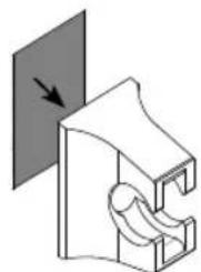
natural_image
Pure mechanical diagram showing a bracket with a curved cutout and an arrow indicating direction (no text or symbols)Abb. FAbb. E Abb. G

natural_image
Technical line drawings of mechanical components including a bracket, gear, roller, and cylindrical parts (no text or labels)FR
Table des matières
natural_image
Pure mechanical component diagram without any text, numbers, or symbolsnatural_image
Technical line drawing of a mechanical spring assembly (no text or symbols)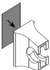
natural_image
Pure mechanical component diagram without any text, numbers, or symbolsFig. F Fig. E Fig. G

natural_image
Technical line drawings of mechanical components including a bracket, gear, roller, and cylindrical shaft (no text or labels)IT
Indice
natural_image
Pure mechanical component diagram without any text, numbers, or symbolsnatural_image
Technical line drawing of a mechanical spring assembly (no text or symbols)
natural_image
Pure mechanical component diagram without any text, numbers, or symbolsFig. F Fig. E Fig. G

natural_image
Technical line drawings of mechanical components including a bracket, washer, roller, and pulley (no text or labels)NL
Inhoudsopgave
natural_image
Pure mechanical component diagram without any text, numbers, or symbols4.2. Montage magneet
natural_image
Technical line drawing of a mechanical spring assembly (no text or symbols)
natural_image
Pure mechanical component diagram without any text, numbers, or symbolsAfb. FAfb. E Afb. G
natural_image
Technical line drawings of mechanical components including a bracket, washer, roller, and pulley (no text or labels)cs
Obsah
natural_image
Pure mechanical component diagram without any text, numbers, or symbols4.2. Montáž magnetu
natural_image
Technical line drawing of a mechanical spring assembly (no text or symbols)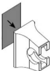
natural_image
Pure mechanical component diagram without any text, numbers, or symbolsObr. FObr. E Obr. G

natural_image
Technical line drawings of mechanical components including a bracket, washer, roller, and pulley (no text or labels)PL
Spis treści
natural_image
Pure mechanical component diagram without any text, numbers, or symbols4.2. Montaż magnesu
natural_image
Technical line drawing of a mechanical component with a spring and housing (no text or symbols)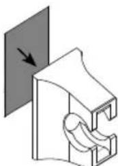
natural_image
Pure mechanical component diagram without any text, numbers, or symbolsRys. FRys. E Rys. G
natural_image
Technical line drawings of mechanical components including a bracket, gear, roller, and cylindrical shaft (no text or labels)PT
Índice
natural_image
Pure technical line drawing of a mechanical component with no text or symbolsnatural_image
Technical line drawing of a mechanical spring assembly (no text or symbols)
natural_image
Pure mechanical component diagram without any text, numbers, or symbolsFig. F Fig. E Fig. G

PT
5. Ligação elétrica
natural_image
Technical line drawings of mechanical components including a bracket, gear, roller, and pulley (no text or labels)SV
natural_image
Pure mechanical component diagram without any text, numbers, or symbolsnatural_image
Technical line drawing of a mechanical component with a spring and threaded end (no text or symbols)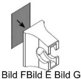
natural_image
Technical line drawings of mechanical components including a bracket, washer, roller, and pulley (no text or labels)Sisällys
natural_image
Pure mechanical component diagram without any text, numbers, or symbolsnatural_image
Technical line drawing of a mechanical spring assembly (no text or symbols)
natural_image
Pure mechanical component diagram without any text, numbers, or symbolsKuva FKuva E Kuva G

5. Sähköliitäntä
natural_image
Technical line drawings of mechanical components including a bracket, gear, roller, and cylindrical parts (no text or labels)RU
Содержание
natural_image
Pure mechanical component diagram without any text, numbers, or symbols4.2. Монтаж магнита
natural_image
Technical line drawing of a mechanical component with a spring and threaded end (no text or symbols)
natural_image
Pure mechanical component diagram without any text, numbers, or symbols
Рис. FPис. E Рис. G
- INSTRUCTIONS FOR INSTALLATION AND USE English
- Table of Contents
- About this instruction manual
- Important information for your safety
- Intended use
- Safety information for the installer
- Product description
- Scope of delivery
- Product features
- Installation
- Mounting the door sensor
- Mounting the magnet
- Electrical connection
- Maintenance
- Disposal
- Technical data
- Door sensor
- Door sensor holder
- Magnet
- Magnet holder
- Türsensor-Set
- MONTAGEANWEISUNG
- Deutsch
- Inhaltsverzeichnis
- Montage Magnet
- Table des matières
- Indice
- Inhoudsopgave
- Montage magneet
- Obsah
- Montáž magnetu
- Spis treści
- Montaż magnesu
- Índice
- Ligação elétrica
- Sisällys
- Sähköliitäntä
- Содержание
- Монтаж магнита
Brand : HARVIA
Model : SAB00103
Category : Door sensor