SH 10 SLi - Boiler STIEBEL ELTRON - Free user manual and instructions
Find the device manual for free SH 10 SLi STIEBEL ELTRON in PDF.
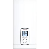
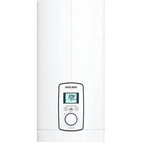
| Product type | Electric pressure boiler |
| Capacity | 10 liters |
| Dimensions (H x W x D) | 503 x 295 x 275 mm |
| Weight | 7.6 kg |
| Electrical supply | 220-240 V, 50/60 Hz, single-phase |
| Rated power | 2.0 kW at 230 V |
| Temperature adjustment range | 35-82 °C |
| Maximum permissible pressure | 0.7 MPa (7 bar) |
| Protection rating | IP 24 D |
| Mounting type | Under-counter installation |
| Hydraulic connection | G 1/2 A (male) |
| Electrical connection | Power plug with earth (type F) |
| Tank material | Polystyrene (PS/EPS) |
| Energy efficiency class | A |
| Annual electricity consumption | 498 kWh |
| Mixed water volume at 40 °C | 19 liters |
| Main functions | Continuous temperature adjustment, heating indicator, frost protection |
| Safety | Safety limiter, safety valve, burn protection |
| Maintenance | Regular descaling, cleaning with damp cloth |
| Available spare parts | Thermostat, safety limiter, connection cable, temperature sensor |
| Included accessories | Wall bracket, mounting template |
| Warranty | According to local subsidiary conditions |
Frequently Asked Questions - SH 10 SLi STIEBEL ELTRON
User questions about SH 10 SLi STIEBEL ELTRON
0 question about this device. Answer the ones you know or ask your own.
Ask a new question about this device
Download the instructions for your Boiler in PDF format for free! Find your manual SH 10 SLi - STIEBEL ELTRON and take your electronic device back in hand. On this page are published all the documents necessary for the use of your device. SH 10 SLi by STIEBEL ELTRON.
USER MANUAL SH 10 SLi STIEBEL ELTRON
BEDIENUNG UND INSTALLATION
OPERATION AND INSTALLATION
UTILISATION ET INSTALLATION
GEBRUK EN INSTALLATIE
OBSŁUGA I INSTALACJA
OBSLUHA A INSTALACE
HASZNÁLATI és TELEPİTESI UTMUTATIO
ÖKÇΠΥATAÇΥ YUCTAHOBKA
Geschlossener (druckfester) Warmwasser-Kleinspeicher | Sealed unvented (pressurised) small water heater | Petit chauffe-eau ECS (sous pression) | Gesloten (drukvaste), kleine warmwaterboiler | Maу, cisnieniowy, pojemnosciowy ogrzewacz wody | Malý tlakový zásobník teplé vody | Kisméretú zárt (nyomásallo) elektramosvizmelegító | ManorabapuTHbý hákONITelbHybý BOODHARpeBaTeNb 3aKpbIToro TUna (HaonopHybý)
SHU 10 SLi
SHU 10 SL GB
SH10SLi
SH 15 SLi
SH 15 SL GB 3,3 kW
STIEBEL ELTRON
BESONDERE HINWEISE
BEDIENUNG
- General information 15
1.1 Safety instructions 15
1.2 Other symbols in this documentation 15
1.3 Units of measurement 15 - Safety 15
2.1 Intended use 15
2.2 Safety instructions 15
2.3 Test symbols 16 - Appliance description 16
3.1 Operation 16 - Cleaning, care and maintenance 16
- Troubleshooting 16
INSTALLATION
- Safety 17
6.1 General safety instructions 17
6.2 Instructions, standards and regulations 17
6.3 Information on the safety assembly 17 - Appliance description 17
7.1 Standard delivery 17
7.2 Accessories 17
8.Preparation 17
8.1 Installation location 17 - Installation 18
9.1 Installing the safety assembly 18
9.2 Appliance installation 18
9.3 Water connection 19
9.4 Electrical connection 19 - Commissioning 20
10.1 Initial start-up 20
10.2 Recommissioning 20 - Settings 20
11.1 Setting the temperature limit 20 - Appliance shutdown 20
- Troubleshooting 20
13.1 Activate high limit safety cut-out 20 - Maintenance 21
14.1 Draining the appliance 21
14.2 Opening the appliance 21
14.3 Descalng the appliance 21
14.4 Checking the earth conductor 21
14.5 Replacing the power cable 21
14.6 Positioning the temperature sensor in its protective pipe 21 - Specification 22
15.1 Dimensions and connections 22
15.2 Wiring diagram 24
15.3 Heat-up diagram 24
15.4 Country-specific approvals and certifications 24
15.5 Extreme operating and fault conditions 24
15.6 Energy consumption data 24
15.7 Data table 25
GUARANTEE | ENVIRONMENT AND RECYCLING
SPECIAL INFORMATION
- The appliance may be used by children aged 8 and older and persons with reduced physical, sensory or mental capabilities or a lack of experience and know-how, provided that they are supervised or they have been instructed on how to use the appliance safely and have understood the potential risks. Children must never play with the appliance. Children must never clean the appliance or perform user maintenance unless they are supervised.
- When permanently connected to the power supply using a dedicated junction box, the appliance must be able to be isolated from the mains power supply by an isolator that disconnects all poles with at least 3mm contact separation.
- The power cable may only be replaced (for example if damaged) by a qualified contractor authorised by the manufacturer, using an original spare part.
- Secure the appliance as described in chapter "Installation / Installation".
- Observe the maximum permissible pressure (see chapter "Installation / Specification / Data table").
- Drain the appliance as described in chapter "Installation / Maintenance / Draining the appliance".
- The appliance is pressurised. During the heat-up process, expansion water will drip from the safety valve.
- Install the safety valve in the cold water supply line.
- Regularly activate the safety valve to prevent it from becoming blocked, e.g. by limescale deposits.
- Size the drain pipe so that water can drain off unimpeded when the safety valve is fully opened.
- Fit the drain pipe of the safety valve with a constant downward slope and in a room free from the risk of frost.
- The safety valve drain must remain open to the atmosphere.
OPERATION
1. General information
The chapters "Special information" and "Operation" are intended for both users and qualified contractors.
The chapter "Installation" is intended for qualified contractors.

Note
Read these instructions carefully before using the appliance and retain them for future reference.
Pass on the instructions to a new user if required.
1.1 Safety instructions
1.1.1 Structure of safety instructions

KEYWORD Type of risk
Here, possible consequences are listed that may result from failure to observe the safety instructions.
Steps to prevent the risk are listed.
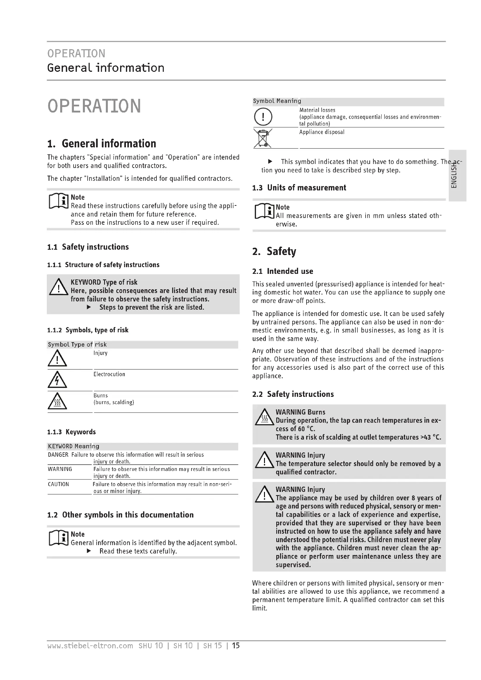
1.1.2 Symbols, type of risk
Symbol Type of risk

Injury

Electrocution

Burns (burns, scale)
1.1.3 Keywords
KEYWORD Meaning
DANGER Failure to observe this information will result in serious injury or death.
WARNING Failure to observe this information may result in serious injury or death.
CAUTION Failure to observe this information may result in non-serious or minor injury.
1.2 Other symbols in this documentation

Note
General information is identified by the adjacent symbol.
Read these texts carefully.
Symbol Meaning

Material losses
(appliance damage, consequential losses and environmental pollution)

Appliance disposal
This symbol indicates that you have to do something. The action you need to take is described step by step.
1.3 Units of measurement

Note
All measurements are given in mm unless stated otherwise.
2. Safety
2.1 Intended use
This sealed unvented (pressurised) appliance is intended for heating domestic hot water. You can use the appliance to supply one or more draw-off points.
The appliance is intended for domestic use. It can be used safely by untrained persons. The appliance can also be used in non-domestic environments, e.g. in small businesses, as long as it is used in the same way.
Any other use beyond that described shall be deemed inappropriate. Observation of these instructions and of the instructions for any accessories used is also part of the correct use of this appliance.
2.2 Safety instructions

WARNING Burns
During operation, the tap can reach temperatures in excess of 60^ .
There is a risk of scalding at outlet temperatures >43^

WARNING Injury
The temperature selector should only be removed by a qualified contractor.

WARNING Injury
The appliance may be used by children over 8 years of age and persons with reduced physical, sensory or mental capabilities or a lack of experience and expertise, provided that they are supervised or they have been instructed on how to use the appliance safely and have understood the potential risks. Children must never play with the appliance. Children must never clean the appliance or perform user maintenance unless they are supervised.
Where children or persons with limited physical, sensory or mental abilities are allowed to use this appliance, we recommend a permanent temperature limit. A qualified contractor can set this limit.

Material losses
If the drain pipe of the safety valve is blocked, expanding water can lead to water damage.
Never close the drain pipe.

Material losses
The user should protect the appliance and its tap against frost.
2.3 Test symbols
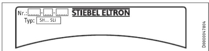
See type plate on the appliance.
3. Appliance description
The appliance constantly keeps the water content available at the preselected temperature. The appliance switches on automatically as soon as its temperature falls below the set value.
Subject to season, varying cold water temperatures can result in different maximum amounts of mixed outlet water.

Note
A qualified contractor can set a temperature limit on the appliance (see "Installation / Settings / Setting the temperature limit").

Note
The appliance is under mains water pressure. The water volume increases as the cylinder is being heated up. During this process, expansion water drips through the safety valve. This is a necessary and normal process.
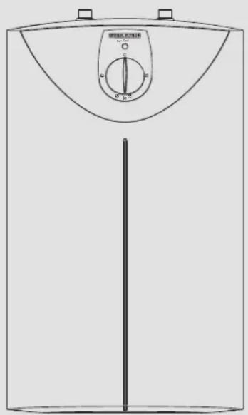
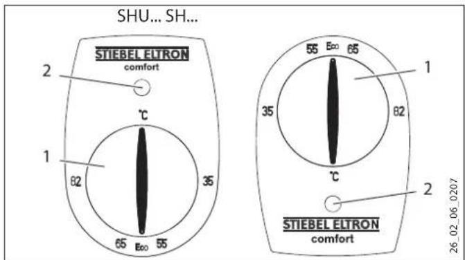
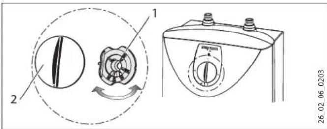
3.1 Operation
You can set any required DHW outlet temperature variably at the temperature selector. The heat-up indicator illuminates during the heat-up process.
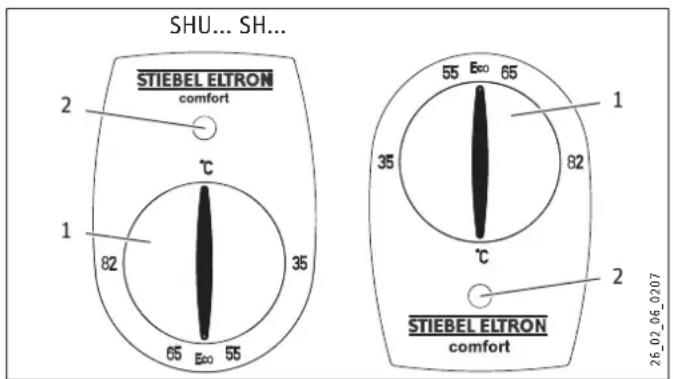
1 Temperature selector
2 Heat-up indicator
Depending on the system, the actual temperatures may vary from the set value.
^ C = Cold. On this setting, the appliance is protected from frost. The tap and the water line are not protected.
Eco = Recommended energy saving setting (approx. 60 °C), minor scaling
82 = Highest selectable temperature
4. Cleaning, care and maintenance
- Never use abrasive or corrosive cleaning agents. A damp cloth is sufficient for cleaning the appliance.
- Check the taps regularly. Limescale deposits at the tap outlets can be removed using commercially available descaling agents.
Have the function of the safety assembly checked regularly by a qualified contractor.
Almost every type of water will deposit limescale at high temperatures. This settles inside the appliance and affects both performance and service life. The heating elements should therefore be descaled if necessary. A qualified contractor who is aware of the local water quality will tell you when the next descending is due.
5. Troubleshooting
| Fault | Cause | Remedy |
| The appliance does not supply hot water. | The temperature selector is set to "0°C". | Switch the appliance ON by turning the temperature selector. |
| No power at the appliance. | Check the plug / fuses in the distribution board. | |
| Reduced water flow rate at the tap. | The aerator in the tap is scaled up. | Descale / replace the aerator. |
| Loud boiling noises inside the appliance. | The appliance is scaled up. | Have the appliance descaled by a qualified contractor. |
| Water drips from the safety valve of the safety assembly after heating has stopped. | The safety valve is scaled up or dirty. | Switch the appliance off. De-pressurise the appliance by disconnecting it from the power and water supply. Have the safety valve checked by a qualified contractor. |
If you cannot remedy the fault, notify your qualified contractor. To facilitate and speed up your request, provide the number from the type plate (000000-0000-000000).
INSTALLATION
6. Safety
Only a qualified contractor should carry out installation, commissioning, maintenance and repair of the appliance.
6.1 General safety instructions
We guarantee trouble-free function and operational reliability only if original accessories and spare parts intended for the appliance are used.
6.2 Instructions, standards and regulations

Note
Observe all applicable national and regional regulations and instructions.
6.3 Information on the safety assembly

Material losses
Never exceed the operating pressure.

Material losses
Route the drain pipe of the safety assembly with a slope and leave it open to atmosphere.

Material losses
The safety equipment requires regular maintenance and activation (see installation instructions of the safety assembly).
7. Appliance description
The appliance is intended for heating cold water and to supply one or several draw-off points.
SHU 10 SLi | SHU 10 SL GB: The sealed unvented (pressurised) appliance is only suitable for undersink installation.
SH 10 SLi | SH 15 SLi | SH 15 SL GB 3.3 kW : The sealed unvented (pressurised) appliance is only suitable for oversink installation.
The appliance may only be installed with pressure taps in conjunction with a safety assembly (see chapter "Installation / Appliance description / Accessories").
7.1 Standard delivery
The following are delivered with the appliance:
- Wall mounting bracket
Installation template
7.2 Accessories
The following accessories are available for sealed unvented operation:
SHU 10 SLi | SHU 10 SL GB
- SVM safety assembly
Water distribution tees - WEH sensor tap
SH 10 SLi | SH 15 SLi | SH 15 SL GB 3.3 kW
Safety assembly KV 40 / KV 307
Surface mounted safety assembly SRT 2
Permanent connection set for 15 | appliances
8. Preparation
Water installation
A safety assembly is required.
Taps/valves
Only install pressure taps in conjunction with a safety assembly.
8.1 Installation location

Material losses
Install the appliance in a room free from the risk of frost.

Material losses
Mount the appliance on the wall. The wall must have sufficient load bearing capacity.

Note
Make sure that the appliance is
freely accessible for maintenance work.
Always install the appliance vertically and near the draw-off point.
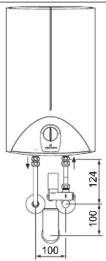
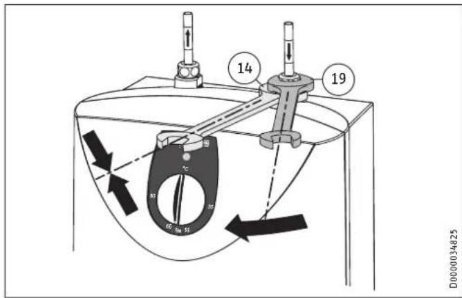
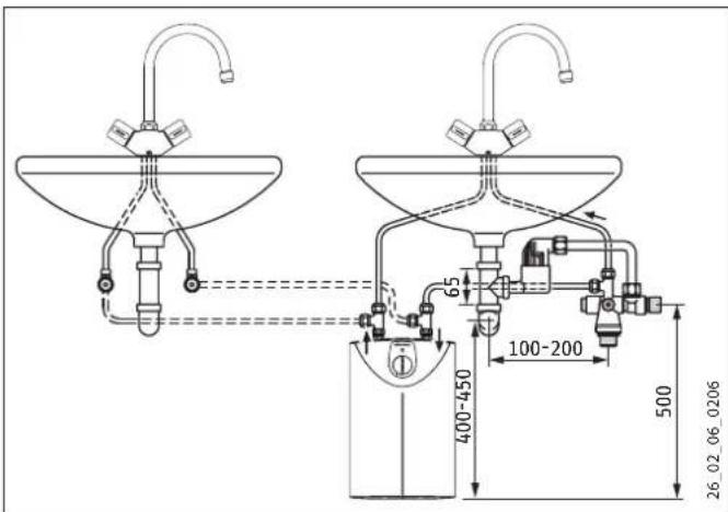
8.1.1 SHU undersink installation with safety assembly
Material losses
The appliance is only suitable for undersink installation.
The water connections of the appliance are at the top.
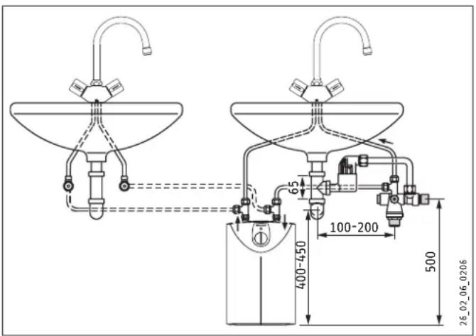
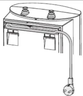
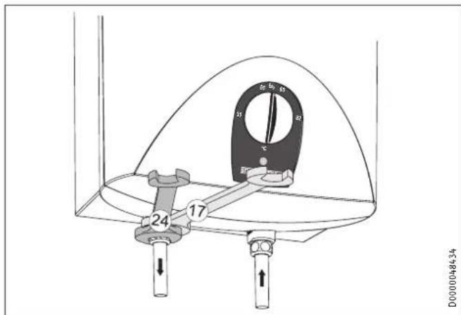
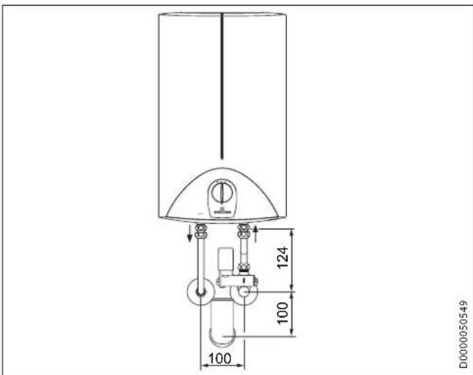
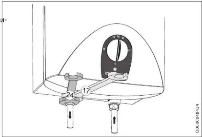
8.1.2 SH oversink installation with safety assembly
Material losses
The appliance is only suitable for oversink installation.
The water connections of the appliance point downwards.
D0000050549
9. Installation
Material losses
When using plastic pipework observe the extreme operating and fault conditions that can occur on the appliance (see chapter "Installation / Specification / Extreme operating and fault conditions").
- Run the connections to the second tap on site, e.g. in 10mm copper pipe.
SHU 10 SLi | SHU 10 SL GB
To supply two washbasins, use the "water distribution tees" (see chapter "Installation / Appliance description / Accessories").
9.1 Installing the safety assembly
Fit the prospective safety assembly in the cold water supply line of the appliance.
Observe the information on the safety assembly (see chapter "Installation / Safety / Information on the safety assembly").
Observe the information in the installation instructions of the safety assembly.
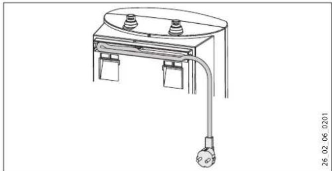
9.2 Appliance installation
Mark out the holes for drilling with the installation template supplied.
Drill the holes and insert suitable rawl plugs.
Secure the wall mounting bracket using suitable screws.
Hang the appliance on the wall mounting bracket.

Note
Surplus cable can be stored in the cable compartment.
26_02_06_0201
9.3 Water connection
Material losses
Carry out all water connection and installation work in accordance with regulations.
Material losses
When tightening the fittings, counterhold with a suitable spanner.

Material losses
The appliance may lose its function.
Never interchange the water connections.
Set the flow rate (see safety assembly instructions).
Observe the maximum permissible flow rate with a fully opened tap (see chapter "Installation / Specification / Data table").
Observe the maximum permissible pressure (see chapter "Installation / Specification / Data table").
Match up the colour coding on the tap water connections anding when converting the appliance. the appliance:
The permanent connection set maintains the IP 24 D protection
R.h. side blue = "Cold water inlet"
- L.h. side red = "DHW outlet"
- Secure the water connections from the tap to the appliance.

Note
Ensure that the water connections are not kinked during installation. Prevent any tensioning during installation.
9.4 Electrical connection

WARNING ELECTROCUTION
Carry out all electrical connection and installation work in accordance with relevant regulations.

WARNING ELECTROCUTION
When permanently connected to the power supply using a dedicated junction box, the appliance must be able to be isolated from the mains power supply by an isolator that disconnects all poles with at least 3mm contact separation.

WARNING ELECTROCUTION
Ensure that the appliance is earthed.

Material losses
The voltage specified on the type plate must match the mains voltage.
Observe the type plate.
The following electrical connections are permissible:
| SHU 10 SLi | SHU 10 SL GB | |
| Connection to a freely accessible standard socket with matching plug | X | - |
| Permanent connection to an appliance junction box with earth conductor | X | X |
| Fixed power cable with the permanent connection set | - | - |
| SH 10 SLi | SH 15 SLi | SH 15 SL GB3.3 kW | |
| Connection to a freely accessible standard socket with matching plug | X | X | - |
| Permanent connection to an appliance junction box with earth conductor | X | X | X |
| Fixed power cable with the permanent connection set | - | X | X |
10. Commissioning

WARNING ELECTROCUTION
Commissioning may only be carried out by a qualified contractor in accordance with safety regulations.
10.1 Initial start-up

Material losses
If you fail to follow the correct sequence (first water, then power), the high limit safety cut-out will trip. Proceed as follows:
If necessary, replace the temperature controller.
Make the high limit safety cut-out operational by pressing the reset button (see chapter "Installation / Troubleshooting / Activating the high limit safety cut-out").
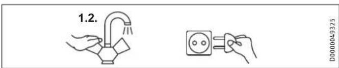
Either open the DHW valve of the tap or set the mono lever mixer tap to "hot" until the water that flows out is free of air bubbles.
Check the safety assembly. When purging, ensure that a full jet of water flows out.
Insert the plug into the standard socket or set the fuse/MCB in the distribution board.
Select a temperature.
Check the entire hydraulic installation for tightness.
10.1.1 Appliance handover
Explain the functions of the appliance to the user. Show the user how to operate the appliance.
Make the user aware of potential dangers, especially the risk of scalding.
- Hand over these instructions and, if applicable, the instructions for any accessories.
10.2 Recommissioning
See chapter "Installation / Commissioning / Initial start-up".
11. Settings
11.1 Setting the temperature limit
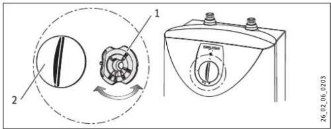
1 Limiting ring
2 Temperature selector
Placing the limiting ring behind the temperature selector allows you to limit the setting range of the temperature selector to a specific maximum temperature.
Turn the temperature selector to zero (fully anti-clockwise to "C").
Pull off the temperature selector and the limiting ring.
- Push the limiting ring with the required maximum setting onto the controller shaft.
Mount the temperature selector set to zero (^)
12. Appliance shutdown
Isolate the appliance from the power supply by removing the plug or by tripping the MCB in the fuse box.
Drain the appliance (see chapter "Installation / Maintenance / Draining the appliance").
13. Troubleshooting
| Fault | Cause | Remedy |
| The appliance does not supply hot water. | The high limit safety cut-out has tripped. | Remedy the cause of the fault. If necessary, replace the temperature controller. Reset the high limit safety cut-out by pressing its reset button. |
| Loud boiling noises inside the appliance. | The appliance is scaled up. | Descale the appliance. |
13.1 Activate high limit safety cut-out
Push the reset button.
14. Maintenance

WARNING Electrocution
Before any work on the appliance, disconnect all poles of the appliance from the power supply.
Dismantle the appliance for maintenance work.
Observe the tightening torque of the flange screws (see chapter "Installation / Maintenance / Installing the flanged immersion heater").
14.1 Draining the appliance

WARNING Burns
Hot water may escape during draining.
Drain the appliance via its connectors.
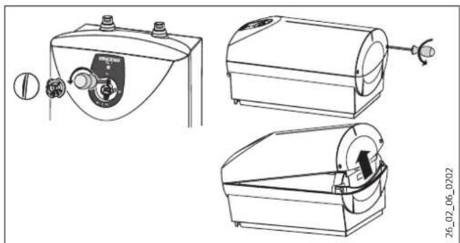
14.2 Opening the appliance
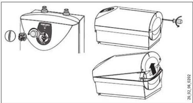
Pull off the temperature selector and the limiting ring.
- Remove the screws from underneath the temperature selector.
- Open the appliance cover by lowering the bolt screws inwards and pivot the cover upwards, then remove it.
SH 10 SLI | SH 15 SLI | SH 15 SL GB 3.3 kW
Undo the tie (anti-tip protection).
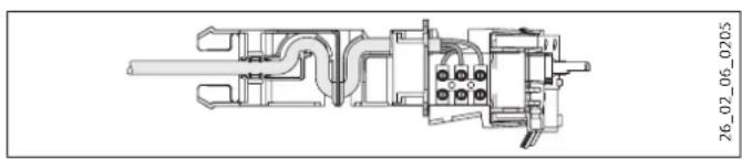
14.5 Replacing the power cable
The power cable must only be replaced by a qualified contractor with an original spare part. As an option, you can also use the following cables:
2 kW appliance
-H05VV-F3x1.0
3.3 kW appliance
-H05VV-F3x1.5
Route the power cable along the cable guide.
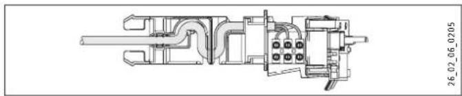
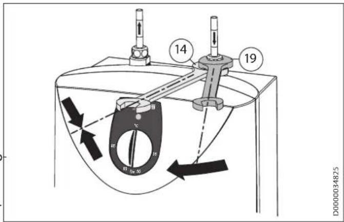
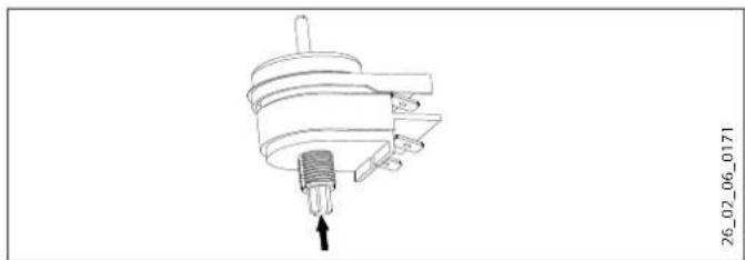
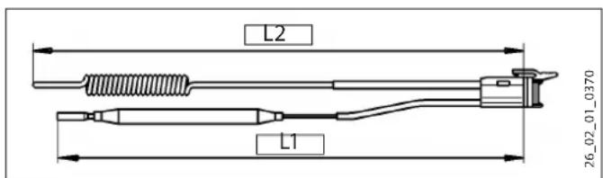
14.6 Positioning the temperature sensor in its protective pipe
- When replacing the temperature controller and the high limit safety cut-out, guide the temperature sensors into the protective pipe.
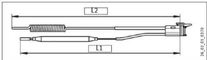
L1 Temperature controller L2 High limit safety cut-out
| L1 L2 | ||
| SHU 10 SLi | 160 | 180 |
| SHU 10 SL GB | 160 | 180 |
| SH 10 SLi | 250 | 160 |
| SH 15 SLi | 310 | 200 |
| SH 15 SL GB 3.3 kW | 320 | 200 |
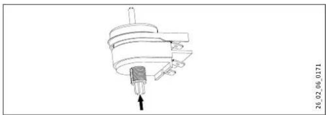
14.3 D escaling the appliance
Remove the flanged immersion heater.
Carefully tap the heating element to remove coarse limescale deposits.
- Immerse the heating element up to the flange plate in descending agent.
14.4 Checking the earth conductor
Check the earth conductor (in Germany DGUV3 for example) across a water connector and the earth conductor contact of the power cable.
15. Specification
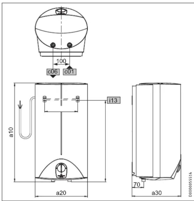
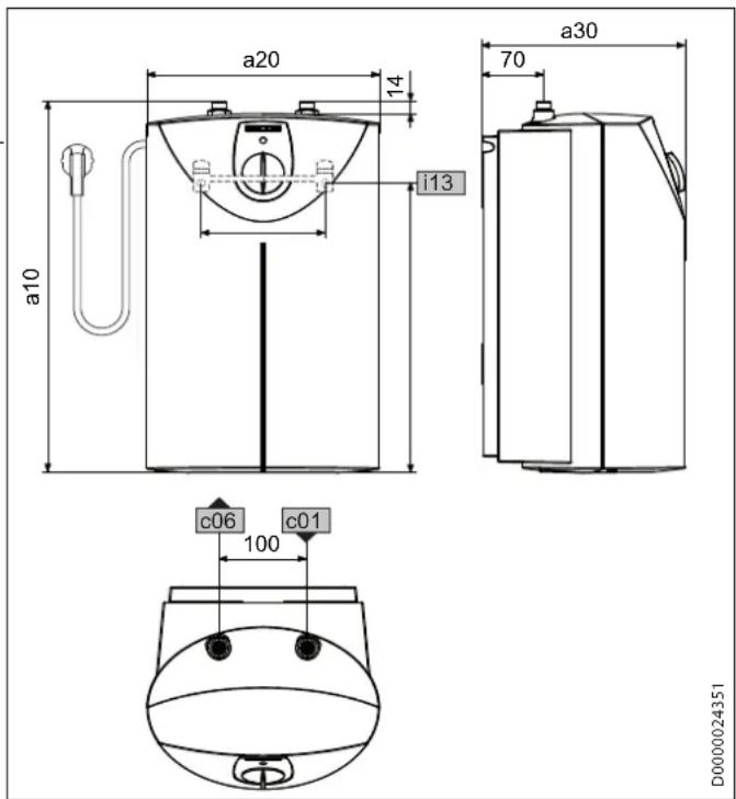
15.1 Dimensions and connections
SHU 10 SLI
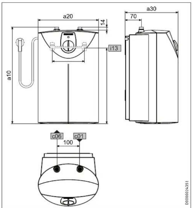
| SHU 10 SLi | ||||
| a10 | appliance | Height mm 503 | ||
| a20 | appliance | Width mm 295 | ||
| a30 | appliance | Depth | mm 275 | |
| c01 | Cold water inlet | Male thread | ||
| c06 | DHW outlet | Male thread | ||
| i13 | Wall mounting bracket | Height mm 363 | ||
| Horizontal hole spacing mm | 200 | |||
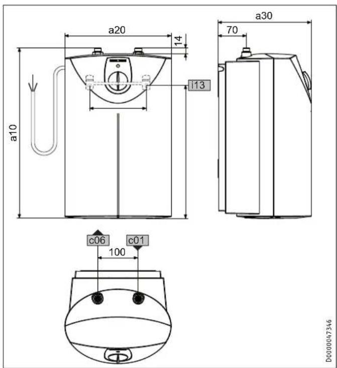
SHU 10 SL GB
| SHU 10 SL GB | ||||
| a10 | appliance | Height | mm | 503 |
| a20 | appliance | Width | mm | 295 |
| a30 | appliance | Depth | mm | 275 |
| c01 | Cold water inlet | Male thread | G 3/8 A | |
| c06 | DHW outlet | Male thread | G 3/8 A | |
| i13 | Wall mounting bracket | Height | mm | 363 |
| Horizontal hole spac- ing | mm | 200 | ||
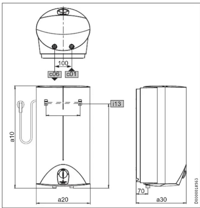
SH 10 SLi | SH 15 SLi
| SH 10 SLi SH 15 SLi | |||||
| a10 | appliance | Height | mm | 503 | 601 |
| a20 | appliance | Width | mm | 295 | 316 |
| a30 | appliance | Depth | mm | 275 | 295 |
| c01 | Cold water inlet | Male thread | G 1/2 A | G 1/2 A | |
| c06 | DHW outlet | Male thread | G 1/2 A | G 1/2 A | |
| i13 | Wall mounting bracket | Height | mm | 387 | 495 |
| Horizontal hole spac-ing | mm | 200 | 200 | ||
SH 15 SL GB 3.3 kW
| SH 15 SL GB 3.3 kW | ||||
| a10 | appliance | Height | mm | 601 |
| a20 | appliance | Width | mm | 316 |
| a30 | appliance | Depth | mm | 295 |
| c01 | Cold water inlet | Male thread | G 1/2 A | |
| c06 | DHW outlet | Male thread | G 1/2 A | |
| i13 | Wall mounting bracket | Height | mm | 495 |
| Horizontal hole spac-ing | mm | 200 | ||
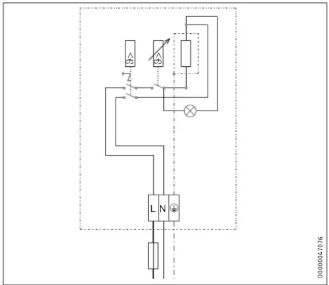
15.2 Wiring diagram
1/N/PE ~ 220 - 240 V
15.3 Heat-up diagram
The heat-up period depends on the degree of scaling and residual heat. For the heat-up time for a cold water supply at 10^ and a maximum temperature setting, see the diagram.
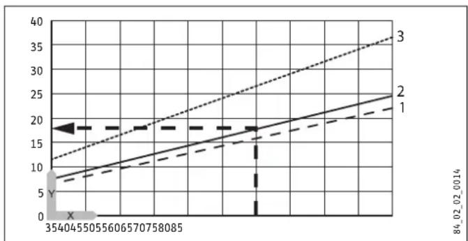
x Temperature in ^ C
y Duration in min
1 3.3 kW 15 | appliance
2 2 kW 10 l appliance
3 2 kW 15 | appliance
Example 10 I appliance:
Temperature setting = 65^
Heat-up time = approx. 18 minutes
15.4 Country-specific approvals and certifications
See the type plate for test symbols.
15.5 Extreme operating and fault conditions
In the case of faults, a peak temperature of up to 105^ may briefly occur in the system.
15.6 Energy consumption data
The product data complies with EU regulations relating to the directive on the ecodesign of energy related products (ErP).
| SHU 10 SLi | SHU 10 SL GB | SH 10 SLi | SH 15 SLi | SH 15 SL GB 3.3 kW | |
| 229473 | 229474 | 229476 | 229478 | 229480 | |
| Manufacturer | Stiebel Eltron | STIEBEL ELTRON | STIEBEL ELTRON | STIEBEL ELTRON | STIEBEL ELTRON |
| Load profile | XXS | XXS | XXS | XXS | XXS |
| Energy efficiency class | A | A | A | A | A |
| Energy conversion efficiency % | 36 | 36 | 37 | 37 | 37 |
| Daily power consumption kWh | 2.371 | 2.371 | 2.318 | 2.314 | 2.314 |
| Annual power consumption kWh | 507 | 507 | 498 | 497 | 497 |
| Default temperature setting °C | 55 | 55 | 55 | 55 | 55 |
| Sound power level dB(A) | 15 | 15 | 15 | 15 | 15 |
15.7 Data table
| SHU 10 SLi SHU 10 SL GB SH 10 SLi SH 15 SLi SH 15 SL GB 3.3 | ||||||||||||||||
| 229473 | 229474 | 229476 | 229478 | kW | ||||||||||||
| Hydraulic data | ||||||||||||||||
| Nominal capacity | I | 10 | 10 | 10 | 15 | 15 | ||||||||||
| Mixed water volume at 40 °C | I | 19 | 19 | 19 | 28 | 28 | ||||||||||
| Electrical data | ||||||||||||||||
| Rated voltage | V | 220 | 230 | 240 | 220 | 230 | 240 | 220 | 230 | 240 | 220 | 230 | 240 | 220 | 230 | 240 |
| Rated output | kW | 1.8 | 2.0 | 2.2 | 1.8 | 2.0 | 2.2 | 1.8 | 2.0 | 2.2 | 1.8 | 2.0 | 2.2 | 3.0 | 3.3 | 3.6 |
| Rated current | A | 8.3 | 8.7 | 9.1 | 8.3 | 8.7 | 9.1 | 8.3 | 8.7 | 9.1 | 8.3 | 8.7 | 9.1 | 13.7 | 14.3 | 15.0 |
| Fuses | A | 10 | 10 | 10 | 10 | 16 | ||||||||||
| Phases | 1/N/PE | 1/N/PE | 1/N/PE | 1/N/PE | 1/N/PE | |||||||||||
| Frequency | Hz | 50/60 | 50/60 | 50/60 | 50/60 | 50/60 | ||||||||||
| Application limits | ||||||||||||||||
| Temperature setting range | °C | Approx. 35 - 82 | Approx. 35 - 82 | Approx. 35 - 82 | Approx. 35 - 82 | Approx. 35 - 82 | ||||||||||
| Max. permissible pressure | MPa | 0.7 | 0.7 | 0.7 | 0.7 | 0.7 | ||||||||||
| Max. flow rate | l/min | 10 | 10 | 10 | 12 | 12 | ||||||||||
| Energy data | ||||||||||||||||
| Standby energy consumption/24 h at 65 °C | kWh | 0.36 | 0.36 | 0.34 | 0.4 | 0.4 | ||||||||||
| Energy efficiency class | A | A | A | A | A | |||||||||||
| Versions | ||||||||||||||||
| IP rating | IP 24 D | IP 24 D | IP 24 D | IP24 | IP 24 D | |||||||||||
| Type of installation | Undersink | Undersink | Oversink | Oversink | Oversink | |||||||||||
| Type | Sealed unvented | Sealed unvented | Sealed unvented | Sealed unvented | Sealed unvented | |||||||||||
| Internal cylinder material | Copper | Copper | Copper | Copper | Copper | |||||||||||
| Thermal insulation material | EPS | EPS | EPS | EPS | EPS | |||||||||||
| Casing material | PS | PS | PS | PS | PS | |||||||||||
| Colour | White | White | White | White | White | |||||||||||
| Connections | ||||||||||||||||
| Electrical connection | Standard plug type F | Cable/lead | Standard plug type F | Standard plug type F | Cable/lead | |||||||||||
| Water connection | G 3/8 A | G 3/8 A | G 1/2 A | G 1/2 A | G 1/2 A | |||||||||||
| Dimensions | ||||||||||||||||
| Depth | mm | 275 | 275 | 275 | 295 | 295 | ||||||||||
| Height | mm | 503 | 503 | 503 | 601 | 601 | ||||||||||
| Width | mm | 295 | 295 | 295 | 316 | 316 | ||||||||||
| Weights | ||||||||||||||||
| Weight | kg | 7.6 | 7.6 | 8.0 | 10.5 | 10.5 | ||||||||||
Guarantee
The guarantee conditions of our German companies do not apply to appliances acquired outside of Germany. In countries where our subsidiaries sell our products a guarantee can only be issued by those subsidiaries. Such guarantee is only granted if the subsidiary has issued its own terms of guarantee. No other guarantee will be granted.
We shall not provide any guarantee for appliances acquired in countries where we have no subsidiary to sell our products. This will not affect warranties issued by any importers.
Environment and recycling
We would ask you to help protect the environment. After use, dispose of the various materials in accordance with national regulations.
REMARQUESPARTICULIERES
UTILISATION
9.3 Raccordement hydraulique

Dommages matériels
WAARSCHUWING verbranding
WAARSCHUWING ELEKTRISCHE SCHOK
WAARSCHUWING ELEKTRISCHE SCHOK
WAARSCHUWING ELEKTRISCHE SCHOK
WAARSCHUWING ELEKTRISCHE SCHOK
WAARSCHUWING verbranding
yTnIn3auny yCtpoNCTBa
3TOT CnMBOJ yKa3bIbaeT Ha Heo6xOIMOCtB BbINONHeHn OnpedeJeHHbIX DeiCTBn. OnncAHne Heo6xOIMbIX DeiCTBn npuBeDeHO Wa 3a WaROM.
1.3 EdnHnCbI n3MepeHnA

Yka3aHne
Ecn He yka3aHo nHoe, Bce pa3MepbI npBBeJeHbI B MnnnMetpax.
2. TexHnka 6e30nacHOCTN
2.1 NcnoB3ObaHne no Ha3HaueHnIO
3TOT np6op 3akpbitoro Tnna (hanopb) npedha3HaueH nla Hara BOOpBOOHO BObI. Pnp6op o6ecneuBaet noaCy ropaeB BObl B ONDy Nn Heckolbo TOeK OT6opa.
Pnp6op npedHa3haeHd 6bITOBORO nCnOJB3OBAHNA. Inerero 6e3onachoro 06cnykunBaHnnoB3OBaTeIO He Tpe6yeTcnpoxoNTb NHTcykTAK.Bo3MOxHO nCnOJB3OBAHNE np6oPaHe ToIbKO B 6bity, Ho n, HapnPmep, Ha npednpnTnxMajoro 6n3heca npu yCNOBn co6JIouDeHnraTex Je ycNobn EKcnjyataqnn.
IIO6oe INHOe IIN He yka3aHHoe B HactoIeM pyKOBOCTBE NcNoJIb3OBAHHe DaHHoro YcTPOJCTBa CHTaETcNcNoJIb3OBAHEm He No Ha3NaYeHIO. NcNoJIb3OBAHne NO Ha3NaYeHIO NOp4a3yMeBaet Co6JIoDeHne Tpe6OBaHn HAcToIeRpyKOBOCTBa, a TAKKe pyKOBOCTB K NcNoJIb3yEmbIM pInHaJNeK-HOCTAM.
2.2 yKa3aHnNo TeXnKe 6e3oNaCHOCTN

PENEYNPEKDEHNEOxor
Bo Bpempa60Tb CmecnteMb MoKet HArpeBaTbcn DO Tempepatpyb CbIwe 60^
Pn TemnepaType BObHa BbIXOe BbIe 43 ^ C cyueCTByET ONaCHOCTb O6BapuBaHna.

PPEUYIPEKDEHNE TpaBma
Pyky peryIaTopa TempepaTypb pa3pewaetc ChMaTb TOnbKO CneuaJIaNCTy.

IPENDYPENKDEHNEtpaBma
DeTAM CTAPWE 8 let, a TAKKHe IINUaM c ORpaHnueHbIMN OHN3NUeCKNIM, CEHCOPHBIMN UYMCTBeHHbIMN CNOCO6HOCTAMN, He IMMeIOUIM ONbITA N He BNaJeIOUIM INHOpMaUneI O np6ope, pa3peSeHO uCNOB3OBaTB np6Op TOlbKO NOp pncmOTpOM dpyrNX LIuN NocLe COOTBETCTByIOUeRO INCHcpykTaXa O npabNax 6e3ONACHO rnoB3OBaHnI N noteHuaNBHOOnacHOCTN B Cnyae HecO6NJIoDEHnA 3TNx npabN. He DonyyckATb 7aNoCTeI DetE C np6OpOM. DeTn MoryT BblONHtB YNCKy np6Opa N Te BnDbl TexHnueckoTo 06CNIYKBaHnIA, KOtOpBle 06bUHO npoN3BOJATCn POJB3OBaTelem, TOlbKO NOd pncmOTpOM B3POCbIX.
Ecn np60pOM NOB3yOTc Detn NnNnUa C orpaHnueHHbIMn
fN3nueckm, ceHCOPhbIMn U yMCTBeHHbIMn cNoC6HOCTAMn,
peKomeHdyeTc yCTaHOBNTb peKIM NOCToRrHORO orpaHnueH
HnTe TmnepaTpybl. HAcToPky DaHHoro pexkma MoKeT BblIOJIHTb CneuaJIInCT.

MATEPnabHbIyuep6
Ecnn CnBna Tpy6ka npedoxpanntbHoro Knanha nepekepbita, BO3MOxKe H yuep6 BcneDCTBne yTeKINBOdbi, paunnpouoeC npnHarpeBe.
He nepekepbIbA Tb CnBHyIO Tpy6Ky!

MATEPnabHbYuep6
Iolb3OBaTeB IOnJKeH o6ecneuHTb 3auNTy npi6opa n CMEcnteTn OT 3aMeP3aHn.
2.3 3HaK TexHnueckoro KOHTpOJa
Cm.3aBODckyToTaBnUcyHa npu6ope.
EbpaaNCKoe COOTBETCTBNE

DAnHbI np6Op COOTBcTByET Tpe6oBaHNM 6e3OnaCHOCTexHHueckOro perlAmeta TaMOxHeHHoro coHO3a I npOwEe COOTBcTByUOHe NPOUeDpybIOdTBePExdHncoOTBcTBN.
3.Описане устpoиства
Pn6bop noctoHHo noidepKnaeT npedBaupntelbHO 3aHaHHyo Temnepatpy Bobl. Ppu naehnn TemnpaTpyb BObl B np6ope Hnke yctahOBHeHHoro 3HaueHnHaRpeB BKIOucaETcra ABtOMaTuYeCKn.
B 3abucmoctn OT BpeMeHr rOa TemnepaTpy XoJIOHOI BObl pa3JIuHaETc, IO3OMy MaKcMmaJIbHbIe O6beMbI CMe- IuaHHoB OBl N O6BeMbI BObl Ha BBIXOe TOKe MOrTy pa3JIuHaTbcR.

Yka3aHne
CneuaJIncIbIMOryT3aIaBaTbHa npIbope orpaHueHne TempepaTypbI (cM. IaBv «UcTaHOBka / HaCTpoKn/ UcTaHOBka OrpaHueHnra TempepaTypbI).

Yka3aHne
Pn6Op HaxountcNoD aBHeHnEM BObI B BODonpoBoe. No Mepe HarpeBa pe3epByapa BOda yBennuBaetcB o6beMe. Pn3TOM BCneCTBne TEnNOBOpOpaunpeHnOHa Kaanaet n3 npedoxpaHnteHoro KlaanaHa. 3To Heo6xOumbIn HOpMaIbHbN npoucecc.
3.1 Θκηνγataμη
HyxHnA TemnepaTpa ropuey BoBbHa BbIXOe NlaBHO Ha-ctpanBaetc nOMoUbpo yuKn peryNtopa TemnepaTpybl.Bo BpemHarpeBa CBETTCs COOTBETCTByIounn HnDnKaTOp.
1 PyuKa peryIaTopa TemnepaTpybI
2 INHnkaTop HarpeBa
TemnepaTpa MoKeT OTKIOHrBcR OT 3aDaHHOrO 3HaueHnA, YTO OByCNOBJeHO CBOICTBaMn CNTEmbl.
°C = Be3 harpeBa. Пи takон HabpoKe npi6op 3aun- uen OT 3aMeP3aHn. CmecnteIb n BOOpnpoBnHaJ nnHnA He 3aunuEhbl.
3ko = PeKOMeHnyemaj HAcTPOJka 3HePrc6eperaIOUero peXIMa (OK. 60 °C), He3HaUnTeJIbHOe 6pa3ObaHne HaKUNI.
82 = MakcmaNbHaHa HAcTpaBaemar TempepaType
CMoHTnpOBaTb np6Op Ha cTeHe. CTeHa DoJnxHa 06BaDaTb DOCTaTOHOn HecuSye CNOCO6HOCTbIO.

Yka3aHne
Длп npоведеня pa6OT NO Textнчeckomy obcnyknBaHnIO np6Op dOJKeH 6bITbIeKo DoCTyneH.
YcTaHaBnBaTb np6Op cneDyET BepTuKaIbHo, B HenocpeICTBeHHo 6JIN3OCTN OT TOKn OT6opa BObl.
8.1.1 MoTaux SHU c npedoxpaHntbHbIM y3nom noD paKOBuHOI

MaTePnAJIbHbIyUeep6
Pnp6op npedha3haueh TOnbko IyctahOBKn NOpaKobHoi. NaTpy6kn Iny NpOKIoueHn BODbl Hnp6ope DOnkHb6bl HapBaJIeHb BBepx.

8.1.2 MoHTaX SH c npedeoxpaHrTeNbHbIM y3nOM Ha paKOBuHOH
MaTePnaiBHybnyuεep6
Pnp6op npedHa3Haeyen TOnbKO dny MOHTaKa Ha paKOBnHO. NaTpy6Kn dny NODKNIOyeHn BObl Ha np6ope DOnKHb 6bl HnPaBHeHb BHN3.
9. MoHTax

MaTePnaiBHyb yuep6
PnncnoB3OBaHnn nactMaccoBbIX Tpy6 Heo6xOAnMo yuHTbBaTb BO3MOXhBle 3KCTpeMaIbHbIe ycIOBnA 3KcNpyataun BepoTHbIe HncnpabHOCTn np60pa (cm. rnaBy «YctaHObKa / TexHnueckne xapaKTepNCtKn / 3KCTpeMaIbHbIe ycIOBnA 3KcNpyataun N Bo3HNKHOBeHne HncnpaBHOCTeN»).
IIOBecTu BOy KO BTOPOMy CmecuTeJIHO 3aKa3uK MoKeT, HApnpMeRc, C NMOUbMoMHeo Tpy6Kn DnAmetpom 10 MM.
SHU 10 SLJSHU 10 SLGB
Дя сабхень ВОДУ MБИВALHINKOB CLE-уET NcONb3OBAt bacpeDenITeHbIe TpoHn-к (сm.глав «Установka /Описнene npибopa /ПринадnexKHOCTN»).
9.1 MoHTaX npeOxpaHnTeNbHoro y3na
CoOTBeCTByUOuI npEoOxApaHHTeNbHy y3eH HyxHO BMOHTnpOBaTbB Tpy60npOBoD NOaHu XOnOHDHOBobl.
Heo6xOJIMO co6IIOaTb yKa3aHnB O THOWeHN npeo xpaHnteJbHoro y3na (cm. rnaBy «YctaHOBka / Be3onac-Hocb / Yka3aHnno npeoxpantehbHomy y3ny)
Heo6xoJIMO co6nOaTb yka3aHn, npBedeHHbE B nHCTpykUIN NO MOHTaxy npedoxpaHntelhoro y3na.
9.2 MoHTax npu6opa
Pa3MeTb MeCTa CBepHeHn OBpECh n C NOMOuI npnaeMOro 7a6NoHa dnn MOHTaxa.
PpocBepnntb OTBepCTnN BCTaBnTb NOxOJaune IIO6eH.
3akpenntb HacteHHyIO MOHTaXHyIO pHaHKy C NOMOsbIO NOxOraux WypynOB.
Habecntb npn6op Ha HacTeHHyIO MOThaKHyIO nHaKy.

Yka3aHne
I3nueK Ka6eN PntaHm MOxHO yOxNTb B Ka6eB HbI OTcE,
9.3 PoiKloueHne K BoJOnpoBody

MaterpnaIbIy uIep6
Bce pa6oTbI NO NOKIOUeHIO BOIy I yCTaHOBKe np6Opa Heo6xOJIMO IpON3BOIDtB CootBeTCTBm C INHCTpyKUne.

MaTePnAJIbHbIy uIepe6
Pn3aTARbAHn pe3b6OBbIX CoeINHeHn Ix CneNyET ydepKbBaTb NODXODaUM raeHbIM KIOUOM OT npoBOPaUNBaHn.

MaTePnAJIbHbIy uIeep6
IHaue npn6op MoKet npnTn B HeroDHOCTb.
He nepenyTaB MeCTAMN COeMHHTeHbIe WJAHr N Dn I NOaH BObl.
3aatab paccxod (cm. pykoobcTBO no 3Kcnnyataun npedoxpahntelhoro y3na).YuHTbBaTb MaKcmmalbHO donyctmbl paXoD npn NOHOCbTOKpbITOM cmecnte (cm. rnaBy «YCTaHOBka /TexHHueckne xapaKtepcntk/N/Tabnua napametropB').
Y6eIHTbCRA,TO TaBJIeHne COOTBeCTByeT MaKcIMaJIbH NONYCTNMOMy (CM. rnaBy (YcTaHOBka / TexHNueCKNe xa- paKTepeNCTnKn / Ta6nua npaMeTpOB)). CCKN
Y6eHtbcra,HTO Cbeta naTpy6KOB dIy NOdkloueHnBdHa cmecntene n npnbope coBnaiaot:
CINHn CBeT (cnpaBa) = NOBOD XONODHO BObl;
-KpaCbHnLBeT(CneBa)=BbInyckropeyB0Dbl.
PpoHNO npBnHTb K naTppy6kam np6opa IJnaHm CMEcNTeIa.

yka3aHne
PnMOHTaxe He DonyckaTb NepereN6OB CoeINHITeB HbIX IuaHROB DnI NOaun BOdb. Pn yCTAHOBKe He DonyckaTb PaCTaRNaHOuXn HapJxKeHn.
9.4 ΘleKtpmueeCKoe nOdkJIIOUeHne

IPENYIPEXJEHNE IOPAXEHN EJKETPNUECKIM TOKOM
Bce pa6oTbI NO 3NeKtpnueckOMy NIOKnIoueHNIO UcTaHOBKe HeO6xOAnMO IpOn3BOUInb B COOTBeTCTBUN C INHCTpyKUneN.

IPEyIpyEeHNE IOPAXEHN EJIKTPUeCKIM TOKOM
Pn Hepa3bemHom NOKIOUeHNN K cTeu cheE3 npB6OpHyo3ETky np6op DOJKeH OTcoeHNrTbcraOT ceTc pactbopor KOHTaKTOB He MeHee 3 MM Ha Bcex noJIocax.

PNEyPPEXJEHNE IOPAXEHN EJKETPNUECKIM TOKOM
PpOBepntb POnkIoueHne np6opa K 3aunTHOMy npoBody.

MaTePnAJIbHbIy uIeep6
HanpexHe B cTe NdoKHO COBnaDaTb C yKa3aHHbIM Ha 3aBOcko Ta6nUKe.
CneNyET co6JIoDaTb daHHbIe Ha 3aBOcKOJ Ta-6nueke.
Ionyctmbi Cneyioune BapnaHTb INeKtpueeCKoro NOkNIO-ueHn:
06bAChNTb HOBOMy NOnb3ObaTeHIO npHcHn pa6oTbnp6opap. No3HaKOMNTb erO C nOpAaKom NOnb3ObaHn np6opom.
YKa3aTb NOpIb3ObaTeIIO HA BO3MOXHbIe ONaCHOCTN,OCo6eHHo Ha OnaCHOCTb 06BapuBaHn.
NpeepaTb HactoJee pyKOBOCTBO n, npn HaJIuHn, pyKOBOCTBa K npHaJNeKHOCTm.
10.2 NOBTOHPbI BBOB B 3KcNpyaTuIO
Cm. rnaBv «UctaHOBka / BbOd B 3KcNpyatauIO / NepBbI BBOB B 3KcNpyatauIO»
11. Hactpoikn
11.1 HactpoJa oRpaHnUHTeIa TempeTaypbI
1OrpaHnHTeJbHoeKoJIbIoo
2 Pyuka perylaTopa TemnepaTpybI
C nomoiBIO orpaHnHTeBHorO KOJIbua NoI pyKoI peryIaTOp a TempePaTypbIMoKHO orpaHnUBaTb Dnana3OH BpaueHnpyuKn, T. e. MaKcImaJIbHyIO TempePaTypy.
PObepHyb pyky peryIaTopa TemnepaTypb B HynEBoe nonoXeHne (do ynpa BnEBO, B noNoXeHne ^
Chrtpyky peryIaTopa TemnepaTypbI orpaHnHTeHHOE KOJIbIO.
YcTaHOBnTb OrpaHnHTeNbHoe KOJbO Ha Ocb peyIaTopa Tempeatpyb TaK, YTo6bI erO NOJOxHeNc COOTBeCTBOBaJIO HxHOMy MaKcMmaJIbHOMy 3HaueHIO.
YcTaHOBnTb pyuKy peryIaTopa TemnepaTypaTb Ka, TTo6bOHA OKa3aIacb B HUneBOM NOIOXKeHmN (C).
12. BbIbOД n3 эКсплуataци
06ecTuNb npn6Op, BbHyB wTeNceIbHyIO BuNKy N3 pO3eTKu IN BbIKNoUH bAToMaTnueCKN BbIKNoUaTeNb DOMOBON 3NeKTPocEtN.
Cnntb Body n3 np6opa (cm. rnaBv «YctaHOBka / Texo6cnykuaBaHne / OnopoxHeHne np6opa').
Pnp6op He HarpBeBaET Body.
Cpa6oTaN ppeOxpaHnteBhbl orpAHnHTeB temnepaTypb
UctpaHnTb npuHny HeNCpapBHOCTN.NOBTOPOHOAKTNBIpObaTb peryIATOP TEMNEpaTypb.CHOBa npuBeCTNnpEOxpaHNTbHbI ORpAHNUHTeB B pexmM rTOBHOCTN,HaxkABeToKHOKNky c6poca.
CunbHbe uMbI B B npu6ope HmeeTcB npu6ope npn Ha- NaKInb. rpeBe BObl.
ydaunb hakinb n npn6opa.
13.1 AkTnBaun npedoxpaHntbHoro orpaHnUHTeTemaNepaTpybl
HaxaTb KhoNky c6poca.
14. Texhnueckoe 6cnykmbaHne
PPEyIPEXJEHIE npaXeHne 3NeKtpuecknM TOkOM Ppei IIO6bIM pa6oTAMn CLEpyET OTKIOHTB BCE noIoca np6opa ot 3NeKtpocetn.
ДЯ pa6OT no Texo6cnyxuBaHnIO np6Op cneyET demOHtnpOBaTb.
Heo6xmoCo6IIOaTb MOMENT 3aT8KIN BuHTOB PhaHua (cm. rnaBv «YctahOBka / TexHuecckoe 06clyKnBaHne / MoHTax K PanaHa c HarpeBaTeJbHbIM THom)).
14.1 OnopoxKHeHne np6opa
PPEyIeHHeOxor
Pn onopoxHeHH np6opa n3 Hero MoKet BbTeKaTb
ropa Boda.
OnopoxHnTb np6Op uepe3 naTp6Kn dIa noKIOueHn BObl.
14.2 OTKpbIbHaHne npu6opa
PYCCKN
Chrtpyky perynrTopa TemnepaTypbI orpaHnHTeJIbHOE KOblO.
BbIKpyTb BnHTbI NOI pyKo peryaTopa TempeaTpbl.
OTkpblk KpbIky np6opa; nIra 3TOrO OTkaTb fNcnpyIOuNE BHTb BHyTpB, NOHrtb KpbIky BBepx INCHtbe.
SH 10 SLi | SH 15 SLi | SH 15 SL GB 3,3 kBt
Pa3OMKHyTbXOMyT (npedoxpaHntb OT ONPOKdbiBaHn).
14.3 YdaJIeHHe NaKIIIM n3 np6opa
ДемоHTирOBaTBФаHeu c HaraPBeBaTeHbIM T3Hom.
CnIbHbIe OTNOxEHNHaKINHa HArpeBaTeNbHOM 3JIemHeTcNeDyET ydaNtB NyTem OCTOpOxHoro NOCTyKnBaHn.
Iorpy3ntbHarpeBaTeNbHbIn 3JeMeHTB CpeCTBO nyaJdaneHnHaKnNn Do ypoBn HnAhnCeBOn nlaCTnHbl.
14.4 NpOBePka 3aunTHoro npoBoHnKa
PpOBepuTb 3aunTHbI npoBODnK (HaNPmep, B TepMaHnn — Ha COOTBeTCTBne HOpMaB GVB A3) Ha nATpy6Ke NOdkJIOUeHnBAOdbi Ha 3a3emnIOUeM KOHTaKTe Ka6enr 3JIeKTPoNITAHn.
14.5 3aMeHa Ka6eIaJIeKtponTuHnA
3aemeny ka6eIeNkTponntaHnna pa3peWSeHO npOn3BODNTb TOIbKO CneuaJIncTy U ToIbKO C NcNoIb3ObaHnEM OpINHaJIb-Horo Ka6eIe. B KaueCTBe aIbTePHTaNBbIMoXHO NcNoJIb3ObaTb Yka3aHHbIe HNXe 3JeKTPuYeCKNe Ka6eII.
Pn6op Mooctbu 2 kBt
H05VV-F3x1,0
Pn6op MoaHocTbIO 3,3 kBt
H05VV-F3x1,5
ynoKntbKa6eB3neKtpoNTaHnB HnpaBnIoUyIO.
14.6 YctaHOBka DaTUnKa TempepaTypbIB 3aunTHyIO Tpy6ky
Pn 3aMeHe TepMoperyIaTopa n npEdoxpaHntbHorO orpaHnHTeJIaTeMnePaTypbI DaTHNK TempePaTypbI CNe- dyET BCTaBtB B 3aUnTHyIO Tpy6Ky.
L1 PerynarTop TemnepaTpybl
L2 PpeoXpaHnTeHbHbO rpaHnHTeHb Tempeatypbl
| L1 | L2 | |
| SHU 10 SLi | 160 | 180 |
| SHU 10 SL GB | 160 | 180 |
| SH 10 SLi | 250 | 160 |
| SH 15 SLi | 310 | 200 |
| SH 15 SL GB 3,3 KBT | 320 | 200 |
15. TexHnueckme xapaKTepeNCTnKN
15.1 Pa3mepbI nOpknloueHn
SHU 10 SLi
JIINTEIbHOCTb HArpeBa=OK.18MnH
15.4 TocydapCTBHeHbIe Donyckn CbndTeNbCTBa
3HaKn TexHnueckoro KOHTpOJa HaxoJrTc Ha 3aBoDcKo Ta-6nueke.
15.5 ΘKCTpeMaJIbHbIe ycNoBnE KcNpyaTaUIM BO3HNKHOBeHHe HEnCnpaBHOCTeI
B cnyuae HncnpaBHOCTn CnCTema MOKeT KpaKOBpeMeHHo HarpeBaTbca Do MaKcImaJIbHOn TemNepaTypbl 105°C.
15.6 XapaKTepeNtukn 3HepronoTpe6NeHnA
XapakTepuctnKn 3dennu COOTBeCTByIOT pernaMeHTaM npeKtnB EC, onpeJenLIOx Tpe6oBaHry K kOOn3aHy 3hePronotpe6nIOUe npOdykun (ErP).
| SHU 10 SLi | SHU 10 SL GB | SH 10 SLi | SH 15 SLi | SH 15 SL GB 3,3 kW | |
| 229473 | 229474 | 229476 | 229478 | 229480 | |
| Поживodител | STIEBEL ELTRON | STIEBEL ELTRON | STIEBEL ELTRON | STIEBEL ELTRON | STIEBEL ELTRON |
| Пробfindангузки | XXS | XXS | XXS | XXS | XXS |
| КлASS Эnéproэф ek-ТИВNOCTN | A | A | A | A | A |
| Эн electriческий КПД | % | 36 | 36 | 37 | 37 |
| Сточные постблике ΚБТ*ч | 2,371 | 2,371 | 2,318 | 2,314 | 2,314 |
| Галовoe постблике ΚБТ*ч | 507 | 507 | 498 | 497 | 497 |
| ЗавODская насточьka Temперауры | °C | 55 | 55 | 55 | 55 |
| Уровед Б зуковою MOОCHOSTN | dB(A) | 15 | 15 | 15 | 15 |
15.7 Ta6nua npaMeTpoB
| SHU 10 SLI SHU 10 SL GB SH 10 SLI SH 15 SLI SH 15 SL GB 3,3 kW | ||||||||||||||
| 229473 | 229474 | 229476 | 229478 | 229480 | ||||||||||
| Гидравлическихарактөриски | ||||||||||||||
| Hошинальнай emкость | I | 10 | 10 | 10 | 15 | 15 | ||||||||
| Колиүстwo смeeшаннoi Воры при 40 °C | I | 19 | 19 | 19 | 28 | 28 | ||||||||
| Өлөдөрүческихарактөриски | ||||||||||||||
| Hошинальhoe наряжениe | V | 220 | 230 | 240 | 220 | 230 | 240 | 220 | 230 | 240 | 220 | 230 | 240 | 220 |
| Hошинальнай мошность | KBТ | 1,8 | 2,0 | 2,2 | 1,8 | 2,0 | 2,2 | 1,8 | 2,0 | 2,2 | 1,8 | 2,0 | 2,2 | 3,0 |
| Hошинальний тok | A | 8,3 | 8,7 | 9,1 | 8,3 | 8,7 | 9,1 | 8,3 | 8,7 | 9,1 | 8,3 | 8,7 | 9,1 | 13,7 |
| П repохарNTель | A | 10 | 10 | 10 | 10 | 16 | ||||||||
| Фаэbl | 1/N/PE | 1/N/PE | 1/N/PE | 1/N/PE | 1/N/PE | |||||||||
| Частota | Hz | 50/60 | 50/60 | 50/60 | 50/60 | 50/60 | ||||||||
| П repетны равочero диалазona | ||||||||||||||
| Диалазон реруліровки temпэратурсы | °C | OK. 35-82 | OK. 35-82 | OK. 35-82 | OK. 35-82 | OK. 35-82 | ||||||||
| Мамс. дәрү_STиме давлиениe | MPa | 0,7 | 0,7 | 0,7 | 0,7 | 0,7 | ||||||||
| Мамс. расхod | π/MIN | 10 | 10 | 10 | 12 | 12 | ||||||||
| Өнөргөдөческихарактөриски | ||||||||||||||
| Расхod оөрөrin в рechimе ожidiадию /24惰а пri 65 °C | KBТ*ч | 0,36 | 0,36 | 0,34 | 0,4 | 0,4 | ||||||||
| Клasc оөр proэфөдөktimbности | A | A | A | A | A | |||||||||
| Мошифкаши | ||||||||||||||
| Стениь заuntы (IP) | IP24 D | IP24 D | IP24 D | IP24 | IP24 D | |||||||||
| Спосб моNTажа | Пов рakовион | Пов рakовион | Над рakовион | Над рakовион | Над рakовион | |||||||||
| Конstруциа | ЗakрытBI | ЗakрытBI | ЗakрытBI | ЗakрытBI | ЗakрытBI | |||||||||
| Мaterиail виитренhero рezервуара | MeДb | MeДb | MeДb | MeДb | MeДb | |||||||||
| Мaterиail төллэдөдөдөдөдөдөдөдөдөдөдөдөдөдөдөдөдөдөдөдөдөдөдөдөдөдөдөдөдөдөдөдөдөдөдөдөдөдөдөдөдөдөдөдөдөдөдөдөдөдөд æрua | EPS | EPS | EPS | EPS | EPS | |||||||||
| Мaterиail корпuya | PS | PS | PS | PS | PS | |||||||||
| ЦВET | 6өлbl | 6өлbl | 6өлbl | 6өлbl | 6өлbl | |||||||||
| Соедиende� | ||||||||||||||
| Өлөдөрүческе радлічениe | ШтениьнayBИПКС CЗAZITNHIMKOHTAKTOM, TIN F | Ka6elb | ШтениьнayBИПКС CЗAZITNHIMKOHTAKTOM, TIN F | ШтениьнayBИПКС CЗAZITNHIMKOHTAKTOM, TIN F | Ka6elb | |||||||||
| Порлічение к ворлічову | G 3/8 A | G 3/8 A | G 1/2 A | G 1/2 A | G 1/2 A | |||||||||
| Размерbl | ||||||||||||||
| Глубиha | MM | 275 | 275 | 275 | 295 | 295 | ||||||||
| Высota | MM | 503 | 503 | 503 | 601 | 601 | ||||||||
| ШирINA | MM | 295 | 295 | 295 | 316 | 316 | ||||||||
| Вec | ||||||||||||||
| Вec | Кr | 7,6 | 7,6 | 8,0 | 10,5 | 10,5 | ||||||||
TapaHTma
Pnp6opby, npno6peTeHHbIe 3a npedeJAMn IepMaHn, He noJaadaOT NOd ycNobria rapaHTNI HemeucKNX K TOMy Xe B CTpaHax, rJe npodaJx HaWei npOdyKcUNO cUyecTBnAET OHa n3 Haunx DoOpEHX KOMNaHn, rapaHTnI npoDocTabIeTcna NCKIOuHTeBHO 3ToI DOOpHeN KOMNaHne. Takar paHTnI npoDocTabJIeTc TOnbKO B Cnyae, ecnn DOpEHeN KOMNaHne n3daHbI CO6CTBeHHbIe ycNobria rapaHTNI. 3a npDeJAMn 3TNX ycNobN Hkakra rapaHTNr He npoDocTabJIeTcN.
Ha npnbopbl, npno6peTeHHbIe B cTpaHax, rIe Hn Onda n3 Haunx doeurhnx KOMnAHn He ocUyecTBnE TpoDAky Hawe npOdykUnn, HnKaKe rapaHTn He pacnpocTpaHnOTc. 3To He 3atparuNaeT rapAHTn, KOtOpBle MOrY T ppeoCTabJIaTbcr MMnopTePOM.
3aunTa OkpykaIoUeI cpebln yTnIn3aun
BheCte CBoi BknaD BoxpaHy Okpykaioe Cpebl. Ytnnn3aunIO NcNoIb3OBAHbIX MaTePnAIOB CneJeYET npOn3BOUNTB COOTBeTCTBm CHaNOnHOHaJIbHbIMn HOpMaMn.
Deutschland
6 Prohasky Street | Port Melbourne VIC 3207
Tel. 03 9645-1833 | Fax 03 9645-4366
info@stiebel.com.au
www.stiebel.com.au
Austria
STIEBEL ELTRON Ges.m.b.H.
Rm 102, F1, Yingbin-Yihao Mansion, No. 1
Yingbin Road
Panyu District | 511431 Guangzhou
Tel. 020 39162209 | Fax 020 39162203
info@stiebeeltron.cn
www.stiebeeltron.cn
Czech Republic
STIEBEL ELTRON spol. s r.o.
K Hajum 946 | 155 00 Praha 5 - Stodulky
Tel. 251116-111 | Fax 235512-122
Urzhumskaya street 4,
building 2 | 129343 Moscow
Tel. 0495 7753889 | Fax 0495 7753887
info@stiebel-eltron.ru
www.stiebel-eltron.ru
Slovakia
TATRAMAT - ohrieva cve vody s.r.o.
Hlavna 1 | 058 01 Poprad
Tel. 052 7127-125 | Fax 052 7127-148
info@stiebel-eltron.sk
www.stiebel-eltron.sk
Switzerland
STIEBEL ELTRON AG
Industrie West
Gass 8 | 5242 Lupfig
Tel. 056 4640-500 | Fax 056 4640-501
info@stiebel-eltron.ch
www.stiebel-eltron.ch
Thailand
STIEBEL ELTRON Asia Ltd.
469 Moo 2 Tambol Klong-Jik
Amphur Bangpa-In | 13160 Ayutthaya
Tel. 035 220088 | Fax 035 221188
info@stiebeeltronasia.com
www.stiebeeltronasia.com
United Kingdom and Ireland
STIEBEL ELTRON UK Ltd.
Unit 12 Stadium Court
Stadium Road | CH62 3RP Bromborough
Tel. 0151 346-2300 | Fax 0151 334-2913
info@stiebel-eltron.co.uk
www.stiebel-eltron.co.uk
United States of America
STIEBEL ELTRON, Inc.
17 West Street | 01088 West Hatfield MA
Tel. 0413 247-3380 | Fax 0413 247-3369
info@stiebel-eltron-usa.com
www.stiebel-eltron-usa.com