HSBB 180 Plus - Boiler STIEBEL ELTRON - Free user manual and instructions
Find the device manual for free HSBB 180 Plus STIEBEL ELTRON in PDF.
User questions about HSBB 180 Plus STIEBEL ELTRON
0 question about this device. Answer the ones you know or ask your own.
Ask a new question about this device
Download the instructions for your Boiler in PDF format for free! Find your manual HSBB 180 Plus - STIEBEL ELTRON and take your electronic device back in hand. On this page are published all the documents necessary for the use of your device. HSBB 180 Plus by STIEBEL ELTRON.
USER MANUAL HSBB 180 Plus STIEBEL ELTRON
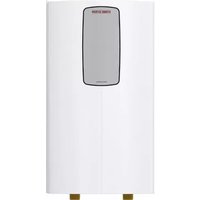
1 = H 2 = L 3 = 4 = +12V
XE02 WHBNGNYEWHBNGNYE GNBNYEWH BNBUGNYE BNBUGNYE XE05 XD01.1
FC07 (1A) MA13 L1 2 K1 K2N
1 = H 2 = L 3 = 4 = +12V
GNBNYEWH BNBUGNYE BNBUGNYE XE05 XD01.1
FC07 (1A) MA13 L1 2 K1 K2N
1 = H 2 = L 3 = 4 = +12V
GNBNYEWH BNBUGNYE BNBUGNYE XE05 XE06XD01.1
SPECIAL INFORMATION - The appliance may be used by children over 8 years of age and persons with reduced physical, sensory or mental capabilities or a lack of ex- perience and expertise, provided that they are supervised or they have been instructed on how to use the appliance safely and have understood the potential risks. Children must never play with the appliance. Cleaning and user maintenance must not be carried out by children without supervision. - The connection to the power supply must be in the form of a permanent connection. Ensure the appliance can be separated from the power sup- ply by an isolator that disconnects all poles with at least 3mm contact separation. - Observe all applicable national and regional reg- ulations and instructions. - Observe minimum distances (see chapter “Instal- lation/ Preparations/ Installation site”). - Only a qualified contractor should carry out in- stallation, commissioning, maintenance and re- pair of the appliance. DHW cylinder - Drain the appliance as described in chapter “Installation/ Maintenance/ Draining the DHW cylinder”. - Observe the maximum permissible pressure (see chapter “Installation/ Specification/ Data table”). - The DHW cylinder is under supply pressure. If no diaphragm expansion vessel is installed, expan- sion water will drip from the safety valve during heat-up. - Regularly activate the safety valve to prevent it from becoming blocked, e.g. by limescale deposits. - The safety valve drain aperture must remain open to atmosphere. SPECIAL INFORMATION OPERATION
1.5 Units of measurement 27
2.2 General safety instructions 28
6. Cleaning, care and maintenance 29
8.1 General safety instructions 30
8.2 Instructions, standards and regulations 30
10.2 Transport and handling 31
11.2 Removing/fitting the front casing 32
11.3 Heating water connection and safety valve 32
11.4 DHW connection and safety assembly 33
11.5 Filling the system 34
11.6 Venting the appliance 35
12. Electrical connection 35
12.1 Electric emergency/booster heater and control voltage 36
13.1 Checks before commissioning the heat pump manager 38
13.2 Commissioning the heat pump manager 38
16.1 Dimensions and connections 40
16.2 Wiring diagram 42
16.3 Energy consumption data 46
The chapters “Special information” and “Operation” are intended for appliance users and qualified contractors.The chapter “Installation” is intended for qualified contractors. Note Read these instructions carefully before using the appli-ance and retain them for future reference.Pass on these instructions to a new user if required.1.1 Relevant documents Operating and installation instructions for the WPM heat pump manager Operating and installation instructions for the connected heat pump Operating and installation instructions for all other sys-tem components1.2 Safety instructions1.2.1 Structure of safety instructions
KEYWORD Type of riskHere, possible consequences are listed that may result from failure to observe the safety instructions.f Steps to prevent the risk are listed.1.2.2 Symbols, type of riskSymbol Type of risk
Burns(burns, scalding) 1.2.3 KeywordsKEYWORD Meaning DANGER Failure to observe this information will result in serious injury or death. WARNING Failure to observe this information may result in serious injury or death.CAUTION Failure to observe this information may result in non-seri-ous or minor injury.1.3 Other symbols in this documentation Note General information is identified by the adjacent symbol.f Read these texts carefully.Symbol Meaning
Material losses(appliance damage, consequential losses and environmen-tal pollution)
Appliance disposal f This symbol indicates that you have to do something. The ac- tion you need to take is described step by step. These symbols show you the software menu level (in this example level3).1.4 Information on the applianceConnectionsSymbol Meaning
1.5 Units of measurement
Note All measurements are given in mm unless stated oth-erwise.
The appliance is used for heating and seasonal cooling of rooms and for DHW heating. For sub dew point cooling, CDT 180 conden- sate pump and condensate pan accessories must be used. With the CDT 180 accessories, cooling rooms is only permissible with monitoring of the dew point. Sub dew point cooling is only ever permissible on a seasonal basis with a subsequent heating period. The appliance is intended for domestic use. It can be used safely by untrained persons. The appliance can also be used in non-do- mestic environments, e.g.in small businesses, as long as it is used in the same way. Any other use beyond that described shall be deemed inappro- priate. Observation of these instructions and of the instructions for any accessories used is also part of the correct use of this appliance.
2.2 General safety instructions
WARNING Burns There is a risk of scalding at outlet temperatures in ex- cess of 43°C.
WARNING Injury The appliance may be used by children over 8 years of age and persons with reduced physical, sensory or men- tal capabilities or a lack of experience and expertise, provided that they are supervised or they have been instructed on how to use the appliance safely and have understood the potential risks. Children must never play with the appliance. Cleaning and user maintenance must not be carried out by children without supervision.
WARNING Injury For safety reasons, only operate the appliance with the front casing closed. Note The DHW cylinder is under supply pressure. If no dia- phragm expansion vessel is installed, expansion water will drip from the safety valve during heat-up. f If water continues to drip when heating is complet- ed, please inform your qualified contractor.
See type plate on the appliance.
3. Appliance compatibility
The appliance can be operated in conjunction with the following air source heat pumps: - WPL-A 05/07 HK 230 Premium - WPL 07-17 ACS classic - HPA-O 05.1/07.1 CS Premium - HPA-O 3-8 CS Plus
4. Appliance description
The appliance comprises a hydraulic module and an integral DHW cylinder and is equipped with a removable front casing. The appli- ance is connected hydraulically and electrically to the heat pump. In addition to the DHW cylinder, the following system components are integrated: - Heat pump manager - Cylinder charging pump/ heating circuit pump - Multifunction assembly with safety valve, 3-way diverter valve and emergency/booster heater for monoenergetic operation DHW cylinder The steel cylinder is equipped with special directly applied enamel coating on the inside and a sacrificial anode. The sacrificial anode protects the cylinder interior from corrosion. The heating water heated by the heat pump is pumped through an indirect coil inside the DHW cylinder. The heat channelled through the indirect coil is thus transferred to the domestic hot water. The integral heat pump manager regulates the DHW heating to the required temperature. Heat pump manager (WPM) The system is controlled by means of the integral heat pump man- ager. The heat pump manager is suitable for the control of a direct heating circuit and a heating circuit with mixer. You can set the times and temperatures for heating operation and heating DHW. Remote controls for controlling the heating circuit are available as accessories. For detailed information, see the enclosed operating and instal- lation instructions for the WPMheat pump manager. Multifunction assembly (MFG) 3-way diverter valve: The multifunction assembly switches be- tween heating circuit and DHW heating. Safety valve: When the pressure is high, the safety valve opens to relieve the pressure in the system. Air vent valve: Components are vented through air vent valves, e.g. pipes or indirect coil.OPERATION Settings www.stiebel-eltron.com HSBB 180 Plus|HSBB 180 S Plus| 29 ENGLISH Emergency/booster heater: in standard mode, the emergency/ booster heater can support the heat pump in monoenergetic mode below the dual mode point. Depending on the setting and connected heat pump, the emergency/booster heater can also be used to back up DHW heating or in pasteurisation mode. In the event of a heat pump malfunction, the emergency/booster heater can temporarily ensure DHW heating and the heating of rooms.
Material losses The system‘s active frost protection is not guaranteed if the power supply is interrupted. f Never interrupt the power supply even outside the heating season. Note The heat pump manager has an automatic summer/win- ter changeover so you can leave the system switched on in summer. The system is controlled by means of the integral heat pump manager. Please observe the heat pump manager operating and installation instructions. OKMENUD0000064711
6. Cleaning, care and maintenance
f Have the electrical safety of the appliance and the function of the safety assembly regularly checked by a qualified contractor. f Have the sacrificial anode checked by a qualified contractor after the first two years of use. The qualified contractor will then determine the intervals at which the sacrificial anode should be checked. f Never use abrasive or corrosive cleaning agents. A damp cloth is sufficient for cleaning the unit.
Problem Cause Remedy The water does not heat up. The heating does not work. There is no power. Check the fuses/ MCBs in your fuse box/ distribu- tion board. Observe the information about troubleshooting in other applicable documents (see chapter “Other applicable documents”). If you cannot remedy the fault, contact your qualified contractor. To facilitate and speed up your enquiry, please provide the serial number from the type plate (000000-0000-000000). No.:000000-0000-000000Made in GermanyD0000102715INSTALLATION Safety 30 | HSBB 180 Plus|HSBB 180 S Plus www.stiebel-eltron.com INSTALLATION
Only a qualified contractor should carry out installation, commis-sioning, maintenance and repair of the appliance.
8.1 General safety instructions
We guarantee trouble-free function and operational reliability only if original accessories and spare parts intended for the unit are used.
8.2 Instructions, standards and regulations
Note Observe all applicable national and regional regulations and instructions.
9. Appliance description
The following are delivered with the appliance: - Operating and installation instructions for the WPM heat pump manager - Outside temperature sensor AFPT - 3adjustable feet - Drain hose - DHW circulation line and flat gasket union nut
Required accessoriesSafety assemblies and pressure reducing valves are available to suit the prevailing supply pressure. These type-tested safety assemblies protect the appliance against impermissible excess pressure.Required for area cooling: - Pt1000 temperature sensor - FET remote controlAdditional accessories - Remote control for heating operation - High limit safety cut-out STB-FB - Water softening fitting HZEA - Segmented anode - CDT 180 condensate pump and condensate pan (required for continuous cooling without dew point monitoring)
Material lossesNever install the appliance in wet rooms.Install the appliance near the draw-off point in a dry room free from the risk of frost. To reduce line losses, keep the distance short between the appliance and the heat pump.Ensure the floor has sufficient load bearing capacity and evenness (for weight, see chapter “Specification/ Data table”).The room must not be subject to a risk of explosions arising from dust, gases or vapours.If you are installing the appliance in a boiler room together with other heating equipment, ensure that the operation of the other heating equipment will not be impaired.Minimum clearances ≥200 ≥400 ≥800 ≥100≥100D0000102716Minimum ceiling clearance: Without DHW circulation 200 mm, with DHW circulation 400 mm. f Maintain the minimum clearances to ensure trouble-free op- eration of the appliance and facilitate maintenance work.INSTALLATION Preparation www.stiebel-eltron.com HSBB 180 Plus|HSBB 180 S Plus| 31 ENGLISH
10.2 Transport and handling
Material losses Store and transport the appliance at temperatures be- tween -20°C and +60°C. Note Two people are required when installing the adjustable feet and transporting the appliance. D0000102526 f Undo the 3screws on the non-returnable pallet.
Material losses Never roll the appliance over the edge of the pallet. Installing supplied carrying straps and adjustable feet Note The carrying straps are intended for one-time use to ma- noeuvre the appliance. D0000102527
1 Carrying strap 2 Washer 3 Adjustable foot 4 Pipe 5 Threaded hole f Slide a pipe over one carrying strap. f Fold over the end of the carrying straps with the two holes and insert an adjustable foot with washers into the carrying strap, as shown in the figure. f Tilt the appliance. f Screw the adjustable foot with the carrying strap into one of the threaded holes (shown in the figure) in the appliance base. f Fit the second carrying strap likewise. f Screw an adjustable foot without a carrying strap into the threaded hole in the appliance base. D0000102717
Material losses Always carry the appliance by the carrying strap. Never transport the appliance using a hoist. During transportation, never subject the pipe connectors to any strain. Protect the appliance against heavy impact during trans- port. f Lift the appliance off the pallet by the carrying straps. f Always use the carrying straps to transport the appliance. f After transportation, tuck the lower carrying straps under the appliance. You can also cut off the upper and lower carrying straps.
f When positioning the appliance, observe minimum clearanc- es (see chapter “Preparations/ Installation site”). f Use the adjustable feet to compensate for any unevenness in the floor.
11.2 Removing/fitting the front casing
Removing the front casing
Material losses If you remove the front panel from the appliance at an angle or unevenly, you may damage it. f Remove the front panel from the appliance by pull- ing it evenly and in a straight line. D0000102719
1 Front panel f Remove the screws on the left and right of the front panel. f Carefully pull the front panel forwards to remove it from the appliance and store it securely so that it cannot tip over, without putting strain on the cable connections. D0000102755 XE06 AA01-X1.18 f To be able to store the upper front panel at a distance from the appliance, loosen the cable tie, unplug the connector from the electronic assembly for operation (AA01-X1.18) and the earth (XE06) at the heat pump manager and store the front panel securely so that it cannot tip over. Fitting the front casing Fit the front casing in reverse order. Take care to position the connection lines correctly and not to pinch any cables.
11.3 Heating water connection and safety valve
Material losses The heating system to which the appliance is connected must be installed by a qualified contractor in accord- ance with the water installation drawings in the technical guides.
Material losses When fitting additional shut-off valves, install a further safety valve in an accessible location on the heat gen- erator itself or in the flow line in close proximity to the heat generator. There must not be a shut-off valve between the heat gen- erator and the safety valve. Note The use of non-return valves in the charging circuits be- tween the heat generator and the buffer or DHW cylin- der can impair the function of the integral multifunction assembly (MFG) and lead to faults in the heating system. f Only use our standard hydraulic solutions for the installation of the appliances. Oxygen diffusion
Material losses Avoid open vented heating systems and underfloor heating systems with plastic pipes that are permeable to oxygen. In underfloor heating systems with plastic pipes that are per- meable to oxygen and in open vented heating systems, oxygen diffusion may lead to corrosion on the steel components of the heating system (e.g. on the indirect coil of the DHW cylinder, on buffer cylinders, steel radiators or steel pipes).INSTALLATION Installation www.stiebel-eltron.com HSBB 180 Plus|HSBB 180 S Plus| 33 ENGLISH
Material losses The products of corrosion (e.g. rusty sludge) can set- tle in the heating system components, which may re- sult in a lower output or fault shutdowns due to reduced cross-sections. Supply lines f The maximum permissible line length between the appli- ance and the heat pump will vary, depending on the version of the heating system (pressure drop). As a standard value, assume a maximum line length of 10m and a pipe diameter of 22mm. f Protect the flow and return lines against frost with sufficient thermal insulation. f Also protect all supply lines against humidity, damage and UV radiation by means of a conduit. f Connect the hydraulic connections with flat gaskets. Pressure differential If the available external pressure difference is exceeded, the pres- sure drop in the heating system could result in a reduced heating output. f When sizing the pipes, ensure that the available external pressure differential is not exceeded (see chapter “Specifica- tion/ Data table”). f When calculating the pressure drop, take account of the flow and return lines and the pressure drop of the heat pump. The pressure drop must be covered by the available pressure differential.
11.3.2 Heating water connection
Installation example:
D0000102721 1 Pipes carrying heating water f Thoroughly flush the pipes before connecting the heat pump. Foreign bodies (e.g. welding pearls, rust, sand, sealant, etc.) can impair the operational reliability of the heat pump. f Install the heating water pipes (see chapter “Specification/ Dimensions and connections”). Safety valve drain hose D0000102532
1 Safety valve drain hose f Unroll the safety valve drain hose connected to the multi- function assembly. f On one of the lower prepared openings on the left or right, remove just enough insulating material as necessary for the drain hose, in order to minimise the exchange of air. f Route the drain hose through the prepared opening from the appliance. f Route the drain hose with a constant fall to a drain. f Ensure that the drain hose is open to the outside. f Secure the drain hose above the drain to prevent any hose movement in the event of water being discharged.
Material losses Route the drain hose to a drain to enable water to drain freely when the safety valve is open.
11.4 DHW connection and safety assembly
Material losses The maximum permissible pressure must not be exceed- ed (see chapter “Specification/ Data table”).
Material losses Operate the appliance only with pressure-tested taps. Note The use of non-return valves in the charging circuits be- tween the heat generator and the buffer or DHW cylin- der can impair the function of the integral multifunction assembly (MFG) and lead to faults in the heating system. f Only use our standard hydraulic solutions for the installation of the appliances. Cold water line Galvanised steel, stainless steel, copper and plastic are approved materials.
Material losses A safety valve is required. DHW line, DHW circulation line Stainless steel, copper and plastic are approved materials.INSTALLATION Installation 34 | HSBB 180 Plus|HSBB 180 S Plus www.stiebel-eltron.com
11.4.2 Fitting the DHW circulation line (optional)
A DHW circulation line with external DHW circulation pump can be fitted to the DHW circulation connection (see chapter “Specifi- cation/ Dimensions and connections”). D0000102536
1 Union nut 2 Insulating sleeve 3 DHW circulation line 4 Gasket 5 “DHW circulation” connection f Remove the sealing cap from the DHW circulation connection (see chapter “Specification/ Dimensions and connections”). f Connect the DHW circulation line with the gasket, the insulat- ing bushing and the flat gasket union nut.
11.4.3 DHW connection and safety assembly
f Flush the pipes thoroughly. f Install the DHW outlet line and the cold water inlet line (see chapter “Specification/ Dimensions and connections”). Con- nect the hydraulic connections. f Install a type-tested safety valve in the cold water supply line. Please note that, depending on the supply pressure, you may also need a pressure reducing valve. f Size the drain pipe so that water can drain off unimpeded when the safety valve is fully opened. f The safety valve drain aperture must remain open to atmosphere. f Install the safety valve drain pipe with a constant fall to the drain.
11.5 Filling the system
Heating circuit water quality Carry out a fill water analysis before filling the system. This analy- sis may, for example, be requested from the relevant water supply utility. To avoid damage as a result of scaling, it may be necessary to soften or desalinate the fill water. The fill water limits specified in chapter “Specification/ Data table” must always be observed. f Recheck these limits 8-12weeks after commissioning and during the annual system service.
Material losses Never switch on the power before filling the system. Note With a conductivity >1000μS/cm, desalination treatment is recommended in order to avoid corrosion. Note If you treat the fill water with inhibitors or additives, the same limits apply as for desalination. Note Suitable appliances for water softening, as well as for filling and flushing heating systems, can be obtained via trade suppliers. Note The appliance offers frost protection for the connection lines in regular operation. In the event of prolonged power failure or when shutting down, drain the DHW side of the appliance. If it is not possible to detect power failures (for example if the system is in a holiday home left vacant for extended periods of time), the following protective measure can be taken. f Add a suitable concentration of ethylene glycol to the fill water. (20-40% by vol.) f Please note that antifreeze changes the density and viscosity of the fill water. Part numberMEG 10 Heat transfer medium as concentrate on an ethylene glycol base231109 MEG 30 Heat transfer medium as concentrate on an ethylene glycol base161696
11.5.1 Filling the heating system
Note Fill the heating system exclusively via the left-hand drain & fill valve. In the delivered condition, the 3-way diverter valve of the mul- tifunction assembly is in its centre position, so that the heating circuit and the heat exchanger for DHW heating are filled evenly. When power is switched on, the 3-way diverter valve automatically switches to heating mode. To fill or drain the system later, you must first place the 3-way diverter valve into its centre position. To set the heat pump manager: f With the MENU key, call up the main menu. f Select the menu or value and confirm with OK:
DIAGNOSIS RELAY TEST SYSTEM DRAIN HYDINSTALLATION
Electrical connection www.stiebel-eltron.com HSBB 180 Plus|HSBB 180 S Plus| 35 ENGLISH D0000102722
f Fill the heating system via the left-hand drain & fill valve. f Vent the pipework.
11.5.2 DHW cylinder filling
f Fill the DHW cylinder via the cold water connection. f Open all downstream draw-off valves until the appliance is full and the pipework is free of air. f Adjust the flow rate. For this, observe the maximum permis- sible flow rate with a fully opened tap (see chapter “Specifi- cation/ Data table”). If necessary reduce the flow rate at the butterfly valve of the safety assembly. f Carry out a tightness check. f Check the safety valve.
11.6 Venting the appliance
1 Air vent valve 2 PCB f Vent the pipework and indirect coil by pulling up the red cap on the air vent valves. f Close the air vent valves after the venting process.
Material losses Close the air vent valves again after venting.
12. Electrical connection
WARNING Electrocution Carry out all electrical connection and installation work in accordance with relevant regulations. f Before any work on the appliance, disconnect all poles from the power supply. WARNING Electrocution The connection to the power supply must be in the form of a permanent connection. Ensure the appliance can be separated from the power supply by an isolator that dis- connects all poles with at least 3mm contact separation. This requirement can be met by using contactors, circuit breakers, fuses/MCBs, etc.
Material losses Provide separate fuses for the two power circuits of the appliance and the control unit.
Material losses Provide separate fuses/MCBs for the two power circuits, i.e. for the compressor and the electricemergency/boost- er heater circuits.
Material losses Observe the type plate. The specified voltage must match the mains power supply. Note You must have permission to connect the appliance from the relevant power supply utility. The terminal box of the appliance is located behind the front casing (see chapter “Installation/ Removing/ fitting the front casing”). D0000102542
f Cut the 4 cable entry plugs (1) only as much as required for the cable diameter in order to minimise the exchange of air.INSTALLATION Electrical connection 36 | HSBB 180 Plus|HSBB 180 S Plus www.stiebel-eltron.com f Route all power supply cables and sensor leads into the ap- pliance through the cable entry from the left or right. From the left, route the cables behind the terminal box to the right-hand side. Lay the lines on the right-hand side through the empty conduits and cable entry plugs. f Connect the power cables and sensor leads as detailed below. Install cables with the following cross-sections in accordance with the respective fuse protection: Fuse protec- tion Assignment Cable cross-section B 16A
Electric emergency/booster heater (DHC) Three-phase2.5mm²1.5mm² with only two live wires, rout-ing according to applicable regulations B 16A
Electric emergency/booster heater (DHC) Single phase2.5mm²1.5mm² when routing a multi-core cable on a wall or in an electrical con-duit on a wallB 16A Control unit 1.5mm²
12.1 Electric emergency/booster heater and control
voltage Appliance functionEffect of the electric emergency/booster heater Mono energetic operation If the dual mode point is undershot, the electric emergen-cy/booster heater safeguards both the heating operation and the provision of high DHW temperatures.Emergency mode Should the heat pump suffer a fault that prevents its con-tinued operation, the heating output will be covered by the electric emergency/booster heater. HSBB180: Electrical connection three-phase
317964-41782D0000102543XD02 Electric emergency/booster heater (DHC)Connected load Terminal assignment 2,9 kW PE N L1 5,9 kW PE N L2 L1 8,8 kW PE N L3 L2 L1 f Connect the electrical emergency/booster heater with the desired rating as detailed in the table. HSBB180S: Electrical connection single phase NL3L2L1317964-41782N L N L317965-38886D0000102544XD02 Electric emergency/booster heater (DHC)Connected load Cable cross-sec- tion Terminal assignment 2,9 kW 2.5mm² PE N L 5,9 kW 2.5mm² PE N L 2.5mm² PE N L f Connect the electrical emergency/booster heater cables to deliver the required rating as detailed in the table. Control voltage
Material losses f Only connect energy efficient circulation pumps ap- proved by us to the pump connections. XD01.2 Heat pump enable signalEVU Enable signal, bus cable to the WPM screened with strain relief in terminal. Heat pump manager terminal assignment WARNING Electrocution Only components that operate with safety extra low voltage (SELV) and that ensure secure separation from the mains voltage supply may be connected to the low voltage terminals of the appliance. Connecting other components can make parts of the ap- pliance and connected components live. f Only use components which have been approved by us.INSTALLATION Electrical connection www.stiebel-eltron.com HSBB 180 Plus|HSBB 180 S Plus| 37 ENGLISH D0000071841 Safety extra low voltage X1.1 CAN A
CAN (connection for heat pump and WPE heat pump extension) X1.2 CAN B
CAN (connection for FET remote control and ISG Internet Service Gateway) X1.3 Signal Earth
Outside sensor X1.4 Signal Earth
Buffer sensor (heating circuit sensor 1) X1.5 Signal Earth
Heating circuit sensor 2 X1.7 Signal Earth
Heating circuit sensor 3 X1.8 Signal Earth
Source sensor X1.10 Signal Earth
CAN (connection for heat pump and WPE heat pump extension) Mains power supply X2.1
Heating circuit pump 1 X2.4
Heating circuit pump 2 X2.5
Heating circuit pump 3 X2.6
Buffer charging pump 1 X2.7
Buffer charging pump 2 X2.8
Source pump/ defrost X2.10
2ndheat source heating X2.13
Note For every appliance fault, output X2.10 issues a 230V signal. In the case of temporary faults, the output switches the signal through for a specific time. In the case of faults that result in a permanent appliance shutdown, the output switches through permanently. Accessories, STB-FB high limit safety cut-out for underfloor heating systems (optional) Netz XD01.1
EVU XD01.2 D0000084472 f Remove the jumper at XD01.1 between L1 and 2. f Connect the STB-FB high limit safety cut-out to XD01.1 be- tween L1 and L2.INSTALLATION Commissioning 38 | HSBB 180 Plus|HSBB 180 S Plus www.stiebel-eltron.com
12.2 Sensor installation
12.2.1 Outside temperature sensor AFPT
The outside temperature sensors have a significant influence on the function of your heating system. Therefore ensure that the outside temperature sensors are correctly positioned and well insulated. - Install the outside temperature sensor on a north or north-eastern wall. - Ensure that the outside temperature sensor is freely exposed to the elements but not placed in direct sunlight. - Never mount the outside temperature sensor above win- dows, doors or air ducts. - Observe the following minimum clearances: 2.5m above the ground and 1m to the side of windows and doors Installation f Remove the cover. f Secure the base with the screw supplied. f Connect the cable. f Connect the outside temperature sensor to AA01-X1.3. f Replace the cover. The cover must audibly click into place.
f Please observe the commissioning instructions for the heat pump manager. The FET remote control is required to record humidity in the case of cooling via an area heating system.
Our customer support can assist with commissioning, which is a chargeable service. If the appliance is intended for commercial use, observe the rules of the relevant Health & Safety at Work Act during commissioning. For further details, check with your local authorising body (in Germany, for example, this is the TÜV).
13.1 Checks before commissioning the heat pump
Material losses Observe the maximum system temperature in underfloor heating systems. f Check that the heating system is filled to the correct pressure and the quick-action air vent valve is closed. f Check whether the outside temperature sensor is correctly placed and connected. f Check whether the power supply is connected correctly. f Check whether the signal cable to the heat pump (bus cable) is correctly connected. High limit safety cut-out Note At temperatures below –15°C the high limit safety cut-out may respond. The appliance may be subjected to these temperatures during storage or transport. D0000102695 HSBB 180 (S) Plus HSBB 180 S Plus
1 High limit safety cut-out reset button f Check whether the high limit safety cut-out has tripped. f If the high limit safety cut-out has triggered, reset it with the reset button.
13.2 Commissioning the heat pump manager
Commission the heat pump manager and make all settings in ac- cordance with the heat pump manager operating and installation instructions. Note For DHW mode, ensure that the PARALLEL OPERATION option is set in the heat pump manager. With this setting, the cylinder charging pump/ heating circuit pump is also activated in DHW mode. To set the heat pump manager: f With the MENU key, call up the main menu. f Select the menu or value and confirm with OK: SETTINGSValue DHW STANDARD SETTING
DHW MODE PARALLEL OPERATION
Note On appliances with a single phase connection, set the heat pump manager as follows for calculating the amount of heat. To set the heat pump manager: f With the MENU key, call up the main menu. f Select the menu or value and confirm with OK: SETTINGSValue HEATING
Material losses Condensation caused by the temperature falling below the dew point can lead to material losses. The appliance is therefore approved exclusively for area cooling. For dew point independent cooling, additional accesso- ries (CDT 180) are required to ensure that any condensate is reliably drained away. f Observe the instructions for the heat pump manager. Adjusting the heat pump manager settings for area cooling: f With the MENU key, call up the main menu. f Select the menu or value and confirm with OK: SETTINGSValue COOLING COOLING ON STANDARD SETTING COOLING CAPACITY system specific ACTIVE COOLING
SET FLOW TEMPERATURE system specific FLOW TEMP HYSTERESIS system specific SET ROOM TEMPERATURE system specific
13.3 Appliance handover
f Explain the appliance function to users and familiarise them with how it works. f Make users aware of potential dangers. f Hand over these instructions.
14. Shutting down the system
Material losses Observe the temperature application limits and the min- imum circulation volume of the heat pump.
Material losses Drain the system when there is a risk of frost and the heat pump is completely switched off (see chapter “Mainte- nance/ Draining the DHW cylinder”). f If you take the system out of use, set the heat pump manager to standby so that the safety functions that protect the appli- ance (e.g. frost protection) remain active.
WARNING Electrocution Carry out all electrical connection and installation work in accordance with relevant regulations. WARNING Electrocution f Before any work on the appliance, disconnect all poles of the appliance from the power supply. Draining the DHW cylinder CAUTION Burns Hot water may escape during draining. f Close the shut-off valve in the cold water supply line. f Open the hot water taps on all draw-off points. D0000102722
f Drain the DHW cylinder via the right-hand drain & fill valve. Testing the sacrificial anode f Arrange for the sacrificial anode to be tested at least every two years and replace immediately if it becomes depleted. For this, observe the maximum transition resistance between the sacrificial anode and the cylinder of 0.3Ω. If it is not possible to insert the sacrificial anode from above, install a segmented anode. The intervals at which subsequent testing should be carried out depends on the wear of the sacrificial anode.INSTALLATION Specication 40 | HSBB 180 Plus|HSBB 180 S Plus www.stiebel-eltron.com
16.1 Dimensions and connections
1 = H 2 = L 3 = 4 = +12V
XE02 WHBNGNYEWHBNGNYE GNBNYEWH BNBUGNYE BNBUGNYE XE05 XD01.1
FC07 (1A) MA13 L1 2 K1 K2N
1 = H 2 = L 3 = 4 = +12V
GNBNYEWH BNBUGNYE BNBUGNYE XE05 XD01.1
FC07 (1A) MA13 L1 2 K1 K2N
1 = H 2 = L 3 = 4 = +12V
GNBNYEWH BNBUGNYE BNBUGNYE XE05 XE06XD01.1
16.3 Energy consumption data
1 = H 2 = L 3 = 4 = +12V
XE02 WHBNGNYEWHBNGNYE GNBNYEWH BNBUGNYE BNBUGNYE XE05 XD01.1
FC07 (1A) MA13 L1 2 K1 K2N
1 = H 2 = L 3 = 4 = +12V
GNBNYEWH BNBUGNYE BNBUGNYE XE05 XD01.1
FC07 (1A) MA13 L1 2 K1 K2N
1 = H 2 = L 3 = 4 = +12V
GNBNYEWH BNBUGNYE BNBUGNYE XE05 XE06XD01.1
1 = H 2 = L 3 = 4 = +12V
XE02 WHBNGNYEWHBNGNYE GNBNYEWH BNBUGNYE BNBUGNYE XE05 XD01.1
FC07 (1A) MA13 L1 2 K1 K2N
1 = H 2 = L 3 = 4 = +12V
GNBNYEWH BNBUGNYE BNBUGNYE XE05 XD01.1
FC07 (1A) MA13 L1 2 K1 K2N
1 = H 2 = L 3 = 4 = +12V
GNBNYEWH BNBUGNYE BNBUGNYE XE05 XE06XD01.1
1 = H 2 = L 3 = 4 = +12V
XE02 WHBNGNYEWHBNGNYE GNBNYEWH BNBUGNYE BNBUGNYE XE05 XD01.1
FC07 (1A) MA13 L1 2 K1 K2N
1 = H 2 = L 3 = 4 = +12V
GNBNYEWH BNBUGNYE BNBUGNYE XE05 XD01.1
FC07 (1A) MA13 L1 2 K1 K2N
1 = H 2 = L 3 = 4 = +12V
GNBNYEWH BNBUGNYE BNBUGNYE XE05 XE06XD01.1
1 = H 2 = L 3 = 4 = +12V
XE02 WHBNGNYEWHBNGNYE GNBNYEWH BNBUGNYE BNBUGNYE XE05 XD01.1
FC07 (1A) MA13 L1 2 K1 K2N
1 = H 2 = L 3 = 4 = +12V
GNBNYEWH BNBUGNYE BNBUGNYE XE05 XD01.1
FC07 (1A) MA13 L1 2 K1 K2N
1 = H 2 = L 3 = 4 = +12V
GNBNYEWH BNBUGNYE BNBUGNYE XE05 XE06XD01.1
1 = H 2 = L 3 = 4 = +12V
XE02 WHBNGNYEWHBNGNYE GNBNYEWH BNBUGNYE BNBUGNYE XE05 XD01.1
FC07 (1A) MA13 L1 2 K1 K2N
1 = H 2 = L 3 = 4 = +12V
GNBNYEWH BNBUGNYE BNBUGNYE XE05 XD01.1
FC07 (1A) MA13 L1 2 K1 K2N
1 = H 2 = L 3 = 4 = +12V
GNBNYEWH BNBUGNYE BNBUGNYE XE05 XE06XD01.1
EasyManual