Frequently Asked Questions - CM 14 BENNING
How to turn on the BENNING CM 14 multimeter?
Press the Ω/A button or the HOLD button. The device is ready when the display shows ----.
How to measure AC voltage?
Connect the black lead to the COM (-/L1) terminal and the red lead to the V/Ω (+/L2) terminal. Turn on the device. Place the test probes on the measurement points. Read the value on the display. The AC symbol appears.
How to measure AC current with the clamp?
Turn on the device, then press the Ω/A button twice until A appears. Open the clamp and place it around a single conductor. Read the current on the display. Do not apply voltage to the terminals during this measurement.
What does the ⚠ symbol on the display mean?
The ⚠ symbol lights up and an audible signal sounds when the measured voltage exceeds 50 V AC or 120 V DC (dangerous voltage threshold). This is a safety warning.
How to test circuit continuity?
Connect the leads as for a voltage measurement. Turn on the device: it is ready in continuity mode (----). Touch the two points of the circuit. If the resistance is less than approximately 1.8-2.7 kΩ, the buzzer sounds and the RX LED lights up.
How to use the auto power off (APO) function?
The device automatically turns off after 10 seconds if no button is pressed and if the auto-power-on conditions are not met. After a resistance measurement (display OL) or current measurement (<1 A), the shutdown occurs after 30 seconds.
When and how to replace the batteries?
Replace the batteries as soon as the battery symbol flashes or all segments are off. Turn off the device and disconnect the leads. Remove the battery compartment cover, insert two 1.5 V AAA (LR03) batteries respecting polarity, then close.
How to perform a phase rotation test?
Connect the black lead to the COM terminal and the red lead to V/Ω. Turn on the device. Place the probes on two phases (L1 and L2) of a three-phase network. If the green LED R▶ lights up, the field rotates clockwise; if the ◀L LED lights up, the field rotates counterclockwise. Perform a cross-check by swapping the probes.
Can the multimeter measure without batteries?
Yes, for AC voltages above 45 V AC or DC voltages above 35 V DC (absolute value). The device then powers directly from the measured circuit, but the display may be less accurate.
How to maintain the BENNING CM 14?
Clean the outer casing with a dry cloth. Never use solvents or abrasives. Check the insulation of the test leads regularly. If the insulation is damaged or a wire is cut, replace the leads immediately. Have the device recalibrated once a year by the BENNING service.
USER MANUAL CM 14 BENNING
BENNING
D Bedienungsanleitung
GB Operating manual
Notice d'emploi
CZ Návod k obsluze
E Instrucciones de servicio
GR Οδηγίες χρήσεως
Istruzioni d'uso
NL Gebruiksaanwijzing
PL Instrukcja obsugi
text_image
CAT.III
1000V
200A~
CAT.IV
600V
VAC 1000
DC 690
400
230
BENNING CM 1-4
BENNING
D Bedienungsanleitung
GB Operating manual
Notice d'emploi
NL Gebruiksaanwijzing
Mehrsprachige Anleitung unter
www.benning.de
Multilingual manuals at

text_image
CAT.III
1000V
200A~
CAT.IV
600V
VAC 1000
DC 690
400
230
< L 120
RD 50 RX
24
+ 12 -
Ω/A
HOLD
2sec
5sec
BENNMS CM 1-4
TRUE RMS
CAT IV 600 V
CAT III 1000 V
+
L2
-
L1

text_image
CAT II 1000V
CAT I: 600V
CAT II 1000V
CAT I: 600V
CAT II 1000V
CAT I: 600V
+2
-1
12
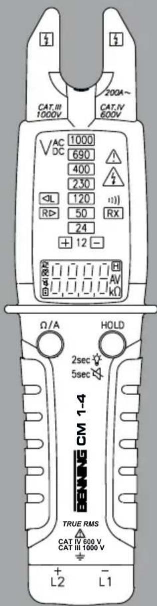
Bild 1a: Gerätefrontseite und Messleitungssatz
Fig. 1a: Device front and set of measuring leads
Fig. 1a : Face avant de l'appareil et jeu de câbles
de mesure
Obr. 1a: Prední část zařízení a sada měřicích vodičů
Fig. 1a: Parte frontal del equipo y cables de medición

text_image
CAT.III
1000V
200A~
CAT.IV
600V
VAC
DC
1000
690
400
230
50
RX
24
+ 12 -
Ω/A
HOLD
2sec
5sec
BEWING CM 1-4
TRUE RMS
CAT IV 600 V.
CAT III 1000 V
L2 L1
①
②
③
④
⑤
⑥
⑦
⑧
⑨
⑩
Εικόνα 1α: Μπροστινό μέρος συσκευής και σετ καλωδίων μέτρησης
III. 1a: Lato frontale apparecchio e set cavi di misura
Fig. 1a: Front apparaat en meetleidingenset
Rys. 1a: Strona przednia urządzenia i zestaw przewodów pomiarowych

text_image
CAT.II 1000V
CAT.II 1000V
CAT.IV 800V
Bild 1b: Verwendung der Aufsteckkappen
Fig. 1b: Using the protective caps
Fig. 1b : Utilisation des capuchons protecteurs
Obr. 1b: Použití nasazovacích krytů
Fig. 1b: Empleo de las tapas extraíbles
Εικόνα 1b: Χρήση των πωμάτων
III. 1b: Utilizzo dei cappucci
Fig. 1b: Gebruik van de opsteekdoppen
Rys. 1b: Zastosowanie nasadek

text_image
19 mm
Bild 1c: Messleitungshalterung
Fig. 1c: Measuring leads holder
Fig. 1c : Support pour câbles de mesure
Obr. 1c: Držák měřicích vodičů
Fig. 1c: Soporte para los cables de medición
Εικόνα 1c: Στήριγμα καλωδίων μέτρησης
III. 1c: Supporto per cavi di misura
Fig. 1c: Houder meetleiding
Rys. 1c: Uchwyt przewodu pomiarowego

text_image
230 V
VAC 1000
DC 690
400
230
50 RX
24
+ 12 -
AC
12-
Bild 2: Wechselspannungsmessung
Fig. 2: Alternating voltage measurement
Fig. 2: Mesure de tension alternative
Obr. 2: Měření střídavého napětí
Fig. 2: Medición de tensión alterna
Εικόνα 2: Μέτρηση αναλλασσόμενου τάσης
III. 2: Misura tensione alternata
Fig. 2: Meten van wisselspanning
Rys. 2: Pomiar napięcia przemiennego

text_image
+
-
12 V
VAC 1000
DC 690
400
230
L 120
R> 50 RX
24
+ 12 -
RL 111 V
-DC
+ 12 -
Bild 3: Gleichspannungsmessung
Fig. 3: Direct voltage measurement
Fig. 3: Mesure de tension continue
Obr. 3: Měření stejnosměrného napětí
Fig. 3: Medición de tensión contínua
Εικόνα 3: Μέτρηση συνεχούς τάσης
III. 3: Misura tensione continua
Fig. 3: Meten van gelijkspanning
Rys. 3: Pomiar napięcia stałego

text_image
100A
CAT.III1000V
CAT.IV600V
VDC
1000
490
400
270
110
80
50
24
12
1.0.0.0A
1.0.0.0A
L2 L1
Bild 4: Wechselstrommessung
Fig. 4: AC current measurement
Fig. 4: Mesure de courant alternatif
Obr. 4: Měření střídavého proudu
Fig. 4: Medición de corriente alterna
Εικόνα 4: Μέτρηση εναλλασμενου ρεύματος
III. 4: Misura corrente alternata
Fig. 4: Meten van wisselstroom
Rys. 4: Pomiar prądu przemiennego

text_image
L1
L2
CAT IN
1000V
CAT IV
600V
200A~
VAC
DC
1000
690
400
730
< L
120
R D>
50
24
+ 12 -
100Ω
100Ω
100Ω
Bild 5: Widerstandsmessung
Fig. 5: Resistance measurement
Fig. 5: Mesure de résistance
Obr. 5: Měření odporu
Fig. 5: Medición de resistencia
Εικόνα 5: Μέτρηση αντίστασης
III. 5: Misura di resistenza
Fig. 5: Weerstandsmeting
Rys. 5: Pomiar rezystancij

text_image
L1
+
-
2
SET
7000V
200A~
200V
VAC
DC
600
400
300
120
80
24
12
RX
-
-
-
-
-
-
-
-
-
-
-
-
-
-
-
-
-
-
-
-
-
-
-
-
-
-
-
-
-
-
-
-
-
-
-
-
-
-
-
-
-
-
-
-
-
-
-
-
-
-
-
-
-
-
-
-
-
-
-
-
Bild 6: Durchgangsprüfung mit Summer
Fig. 6: Continuity testing with buzzer
Fig. 6: Contrôle de continuité avec ronfleur
Obr. 6: Zkouška průchodnosti s bzučákem
Fig. 6: Comprobación de continuidad con sistema de vibración.
Εικόνα 6: Έλεγχος συνέχειας με βομβητή
III. 6: Test di continuità con cicalino
Fig. 6: Doorgangstest met akoestisch signaal
Rys. 6: Test ciągłości obwodu z brzęczykiem

text_image
L1
L2
L3
L1
L2
L3
R
3000
3000
V
A
B
C
D
E
F
G
H
I
J
K
L1
L2
L3
Bild 7.1: Drehfeldrichtungsprüfung (Rechtsdrehfeld)
Fig. 7.1: Phase sequence test (clockwise)
Fig. 7.1 : Test d'ordre de phases (sens horaire)
Obr. 7.1: Kontrola sledu fází (sled fází vpravo)
Fig. 7.1: Comprobación del sentido del campo giratorio (campo giratorio derecho)
Εικόνα 7.1: Έλεγχος ακολουθίας φάσεων (πεδίο
περιστροφής δεξιόστροφα)
III. 7.1: Test della sequenza di fase (rotazione a destra)
Fig. 7.1: Draaiveldrichtingcontrole (rechts draaiveld)
Rys. 7.1: Test kierunku wirowania pola (kierunek wirowania w prawo)

text_image
L1
L2
L3
L2
L1
L3
Lng (Linksdrehfeld)
counter-clockwise)
s (sens anti-horaire)
ed fázi vlevo)
tido del campo giratorio
ierdo)
φάσεων (πεδίο περιστροφής
ns (retarise e sinistra)
Bild 7.2: Drehfeldrichtungsprüfung (Linksdrehfeld)
Fig. 7.2: Phase sequence test (counter-clockwise)
Fig. 7.2 : Test d'ordre de phases (sens anti-horaire)
Obr. 7.2: Kontrola sledu fází (sled fází vlevo)
Fig. 7.2: Comprobación del sentido del campo giratorio (campo giratorio izquierdo)
Εικονα 7.2: Έλεγχος ακολουθίας φάσεων (πεδίο περιστροφής αριστερόστροφα)
III. 7.2: Test della sequenza di fase (rotazione a sinistra)
Fig. 7.2: Draaiveldrichtingcontrole (links draaiveld)
Rys. 7.2: Test kierunku wirowania pola (kierunek wirowania w lewo)

text_image
N
L
(mnzeige)
phase indication)
extérieur (indiction de phase)
Bild 8: Einpolige Außenleiterprüfung (Phasenanzeige)
Fig. 8: Single-pole external conductor test (phase indication)
Fig. 8 : Contrôle unipolaire du conducteur extérieur (indication de phase)
Obr. 8: Kontrola jednopólového vnějšího vodiče (fázové zobrazení)
Fig. 8: Comprobación de la fase unipolar (indicador de fases)
Εικόνα 8: Έλεγχος μονοπολικού εξωτερικού αγωγού (ένδειξη φάσης)
III. 8: Controllo unipolare della fase (visualizzazione fase)
Fig. 8: Eenpolige buitengeleidercontrole (fase-indicatie)
Rys. 8: Jednobiegunowy test przewodu zewnętrznego (wyświetlacz fazowy)

text_image
1.5V AAA x 2
Bild 9: Batteriewechsel
Fig. 9: Battery replacement
Fig. 9: Remplacement de la pile
Obr. 9: Výměna baterie
Fig. 9: Cambio de pila
Εικόνα 9: Αντικατάσταση μπταταρίας
III. 9: Sostituzione batterie
Fig. 9: Vervanging van de batteri
Rys. 9: Wymiana baterii
Bedienungsanleitung BENNING CM 1-4
TRUE RMS Multimeter mit offener Stromzange zur
\- Wechselstrommessung
\- Wechselspannungsmessung
\- Gleichspannungsmessung
\- Einpolige Außenleiterprüfung (Phasenanzeige)
\- Drehfeldrichtungsprüfung
\- Polaritätsprüfung
\- Widerstandsmessung
\- Durchgangsprüfung
Inhaltsverzeichnis
1. Benutzerhinweise
2. Sicherheitshinweise
3. Lieferumfang
4. Gerätebeschreibung
5. Allgemeine Angaben
6. Umgebungsbedingungen
7. Elektrische Angaben
8. Messen mit dem BENNING CM 1-4
9. Instandhaltung
10. Technische Daten des Messzubehörs
11. Umweltschutz
1. Benutzerhinweise
Diese Bedienungsanleitung richtet sich an
- Elektrofachkräfte und
- elektrotechnisch unterwiesene Personen
Das BENNING CM 1-4 ist zur Messung in trockener Umgebung vorgesehen und darf nicht in Stromkreisen mit einer Spannung höher als 1000 V AC/DC eingesetzt werden (Näheres hierzu in Abschnitt 6. "Umgebungsbedingungen").
In der Bedienungsanleitung und auf dem BENNING CM 1-4 werden folgende Symbole verwendet:

Anlegen um GEFÄHRLICHE AKTIVE Leiter oder Abnehmen von diesen ist zugelassen.

Warnung vor elektrischer Gefahr!
Steht vor Hinweisen, die beachtet werden müssen, um Gefahren für Menschen zu vermeiden.

Achtung Dokumentation beachten!
Das Symbol gibt an, dass die Hinweise in der Bedienungsanleitung zu beachten sind, um Gefahren zu vermeiden.
Messkategorie III ist anwendbar für Prüf- und Messstromkreise, die CAT III am Verteilerkreis der Niederspannungs-Netzinstallation des Gebäudes angeschlossen sind.
Messkategorie IV ist anwendbar für Prüf- und Messstromkreise, die am CAT IV Einspeisepunkt der Niederspannungs-Netzinstallation des Gebäudes angeschlossen sind.

Dieses Symbol auf dem BENNING CM 1-4 bedeutet, dass das Gerät schutzisoliert (Schutzklasse II) ausgeführt ist.

Bedienungsanleitung beachten.

Dieses Symbol erscheint in der Anzeige für eine entladene Batterie.

Dieses Symbol kennzeichnet den Bereich "Durchgangsprüfung". Der Summer dient der akustischen Ergebnisausgabe.

(DC) Gleichspannung.

(AC) Wechsel-Spannung oder Strom.

Masse (Spannung gegen Erde).
2. Sicherheitshinweise
Das Gerät ist gemäß
DIN VDE 0411 Teil 1/ EN 61010-1
DIN VDE 0411 Teil 2-032/EN 61010-2-032
DIN VDE 0411 Teil 2-033/EN 61010-2-033
DIN VDE 0411 Teil 031/EN 61010-031
gebaut und geprüft und hat das Werk in einem sicherheitstechnisch einwandfreien Zustand verlassen.
Um diesen Zustand zu erhalten und einen gefahrlosen Betrieb sicherzustellen, muss der Anwender die Hinweise und Warnvermerke beachten, die in dieser Anleitung enthalten sind. Fehlverhalten und Nichtbeachtung der Warnungen können zu schwerwiegenden Verletzungen oder zum Tode führen.

Extreme Vorsicht bei Arbeiten um blanke Leiter oder Hauptleitungsträger. Ein Kontakt mit Leitern kann einen Elektroschock verursachen.

Das BENNING CM 1-4 darf nur in Stromkreisen der Überspannungskategorie III mit max. 1000 V Leiter gegen Erde oder Überspannungskategorie IV mit max. 600 V Leiter gegen Erde benutzt werden.
Hierzu sind geeignete Messleitungen zu verwenden. Bei Messungen innerhalb der Messkategorie III oder der Messkategorie IV darf das hervorstehende leitfähige Teil einer Kontaktspitze der Messleitung nicht länger als 4 mm sein.
Vor Messungen innerhalb der Messkategorie III und der Messkategorie IV müssen, die dem Set beigestellten, mit CAT III und CAT IV gekennzeichneten, Aufsteckkappen auf die Kontaktspitzen aufgeschraubt werden. Diese Maßnahme dient dem Benutzerschutz.
Beachten Sie, dass Arbeiten an spannungsführenden Teilen und Anlagen grundsätzlich gefährlich sind. Bereits Spannungen ab 30 V AC und 60 V DC können für den Menschen lebensgefährlich sein.

Bei Messungen von Spannungen > 300 V das BENNING CM 1-4 nie länger als 30 Sekunden an Spannung anlegen. Bei Spannungen > 300 V beträgt die maximale Einschaltzeit tON: 30s und die Erholzeit tOFF: 240 s.

Vor jeder Inbetriebnahme überprüfen Sie das Gerät und die Leitungen auf Beschädigungen.

Das BENNING CM 1-4 beim Benutzen immer an der gummierten Grifffläche hinter der Griffbegrenzung anfassen.
Ist anzunehmen, dass ein gefahrloser Betrieb nicht mehr möglich ist, ist das Gerät außer Betrieb zu setzen und gegen unbeabsichtigten Betrieb zu sichern.
Es ist anzunehmen, dass ein gefahrloser Betrieb nicht mehr möglich ist,
\- wenn das Gerät oder die Messleitungen sichtbare Beschädigungen aufweisen,
\- wenn das Gerät nicht mehr arbeitet,
\- nach längerer Lagerung unter ungünstigen Verhältnissen,
\- nach schweren Transportbeanspruchungen.
\- wenn das Gerät und die Messleitungen feucht sind.

Um eine Gefährdung auszuschließen
\- berühren Sie die Messleitungen nicht an den blanken Kontaktspitzen,
\- stecken Sie die Messleitungen in die entsprechend gekennzeichneten Messbuchsen am Multimeter und kontrollieren Sie den festen Sitz.

Wartung:
Das Gerät nicht öffnen, es enthält keine durch den Benutzer reparablen Bauteile. Reparatur und Service kann nur durch qualifiziertes Personal erfolgen.

Reinigung:
Das Gehäuse regelmäßig mit einem Tuch und Reinigungsmittel trocken abwischen. Kein Poliermittel oder Lösungsmittel verwenden.
3. Lieferumfang
Zum Lieferumfang des BENNING CM 1-4 gehören:
3.1 ein Stück BENNING CM 1-4
3.2 ein Stück Sicherheitsmessleitung, rot (L = 1,4 m)
3.3 ein Stück Sicherheitsmessleitung, schwarz (L = 1,4 m)
3.4 ein Stück Kontaktspitzenschutz zum Schutz vor Verletzungen, befestigt an schwarzer Sicherheitsmessleitung. Inkl. ein Satz Aufsteckkappen (CAT III/ IV) rot/schwarz zur Längenreduzierung vom unisolierten Teil der Kontaktspitzen und ein Satz 4 mm ∅ Kontaktspitzenvergrößerung (CAT II).
3.5 ein Stück Gürtel-Holster
3.6 zwei Stück 1,5 V-Micro-Batterie (zur Erstbestückung im Gerät eingebaut)
3.7 eine Bedienungsanleitung
Hinweis auf Verschleißteile:
- Das BENNING CM 1-4 wird durch zwei eingebaute 1,5-V-Micro-Batterien (IEC LR 03) gespeist.
- Die oben genannten Sicherheitsmessleitungen (geprüftes Zubehör, rot/ schwarz) entsprechen bei montierten Aufsteckkappen CAT III 1000 V/ CAT IV 600 V und sind für einen Strom von 10 A zugelassen. Der Messleitungssatz (T.-Nr. 10217482) beinhaltet den Kontaktspitzenschutz inkl. der Aufsteckkappen (CAT III/ IV) und die 4 mm ∅ Kontaktspitzenvergrößerungen (CAT II).
- Der Kontaktspitzenschutz inkl. der Aufsteckkappen (CAT III/ IV) und die 4 mm ∅ Kontaktspitzenvergrößerungen (CAT II) kann über T.-Nr. 10217843 separat bestellt werden.
- Der Gürtel-Holster ist über die T.-Nr. 10217845 bestellbar.
4. Gerätebeschreibung
siehe Bild 1a: Gerätefrontseite und Messleitungssatz
Die in Bild 1a angegebenen Anzeige- und Bedienelemente werden wie folgt bezeichnet:
Offene Stromzange, zum Einführen und „Umfassen“ des einadrigen wechselstromdurchflossenen Leiters
② LED-Messstellenbeleuchtung
③ LED-Anzeige, angezeigt werden
\- die Spannungsstufen 12 V - 1000 V
- das Symbol für die Überschreitung der ELV-Grenze (50 V AC/ 120 V DC), wird auch für die Außenleiterprüfung (Phasenanzeige) verwendet
- das Symbol für die Durchgangsprüfung RX
- die Symbole für die Drehfeldrichtungsprüfung (links/ rechts)
\- die Polaritätsanzeige + -
4 Digitalanzeige (Flüssigkristallprinzip), angezeigt werden - der Messwert mit der max. Anzeige 9999 und Dezimalpunkt
- der festgehaltene Messwert (Holdfunktion)
- die Spannungsart AC/DC
- die Einheiten V (Spannung), A (Strom), Ω (Widerstand)
- das Symbol des deaktivierten Signaltons bei Spannungsmessung
- das Batteriesymbol mit max. 3 Segmenten
5 Griffbegrenzung, schützt vor Leiterberührung
⑥ Ω/A-Taste, Umschaltung Widerstands-/ Strommessbereich
7 HOLD-Taste (Haltefunktion)/ Aktivierung der Messstellenbeleuchtung (2 s)/ Deaktivierung des Signaltons bei Spannungsmessung (5 s)
8 Gummierte Grifffläche
9 schwarze Buchse (-/L1), gemeinsame Buchse für Spannungs-/ Widerstandsmessung und Durchgangsprüfung
⑩ rote Buchse (+/L2) (positiv 1), für V und Ω
⑪ Kontaktspitzenschutz mit Aufsteckkappen (CAT III/ IV) und 4 mm ∅ Kontaktspitzenvergrößerung (CAT II)
12 Sicherheitsmessleitungssatz (rot/schwarz) inkl. Kontaktspitzenschutz mit Aufsteckkappen (CAT III/ IV) und 4 mm ∅ Kontaktspitzenvergrößerung (CAT II)
1) Hierauf bezieht sich die automatische Polaritätsanzeige für Gleichspannung
5. Allgemeine Angaben
5.1 Allgemeine Angaben zum Digital-Multimeter
5.1.1 Die Digitalanzeige ④ ist als 4-stellige Flüssigkristallanzeige mit 13 mm Schrifthöhe und Dezimalpunkt ausgeführt. Der größte Anzeigewert ist 9999.
5.1.2 Die Polaritätsanzeige in der Digitalanzeige ④ wirkt automatisch. Es wird nur eine Polung entgegen der Messleitungsdefinition mit “-” angezeigt. Ab 12 V wird die Polarität zusätzlich durch das Aufleuchten der LED oder der LED angezeigt.
5.1.3 Die Bereichsüberschreitung wird mit „0L“ oder „- 0L“ angezeigt.
Achtung, keine sonstige Anzeige und Warnung bei Überlast!
5.1.4 Ω/A-Taste: Durch Betätigen der Ω/A-Taste ⑥ wird in den Widerstandsmessbereich (Ω) geschaltet. Erneutes Betätigen der Taste schaltet in den Strommessbereich (A) weiter. Eine Betätigung von 2 s schaltet in den Spannungsmessbereich (Anzeige - - - - ) zurück.
5.1.5 Die HOLD-Taste ⑦ hat drei Funktionen:
\- Messwertspeicherung „HOLD“: Durch Betätigen der Taste „HOLD“
7 lässt sich das Messergebnis speichern. Im Display wird gleichzeitig das Symbol Heingeblendet. Erneutes Betätigen der Taste schaltet in den Messmodus zurück.
\- Messstellenbeleuchtung: Drücken und halten der Taste „HOLD“ für 2 s schaltet die LED der Messstellenbeleuchtung ein.
\- Signalton bei Spannungsmessung: Drücken und halten der Taste „HOLD“ ⑦ für 5 s deaktiviert den Signalton bei Spannungsmessung, siehe Abschnitt 8.3 „Akustischer Signalton bei Spannungen > 50 V AC/ 120 V DC“.
5.1.6 Die Messrate der Ziffernanzeige des BENNING CM 1-4 beträgt nominal ca. 3 Messungen pro Sekunde.
5.1.7 Das BENNING CM 1-4 lässt sich durch Betätigung der Ω/A-Taste ^6 oder der HOLD-Taste ^7 einschalten. Die Bereitschaft zur Spannungsmessung, einpolige Außenleiterprüfung und Durchgangsprüfung wird durch das Symbol „- - - -“ in der Digitalanzeige ^4 angezeigt. Unter folgenden Bedingungen erfolgt die Einschaltung automatisch:
Batterien mit ausreichender Batteriespannung eingelegt:
\- Messspannung zwischen Buchse + / L2 10 und Buchse - / L1 9 > 3 V oder < -8 V
\- Einpolige Außenleiterprüfung erkennt die Phasenspannung
\- Durchgangsprüfung erkennt Widerstand < 1,8 kΩ - 2,7 kΩ
Keine Batterien eingelegt oder Batteriespannung zu schwach:
\- Messspannung zwischen + / L2 10 und Buchse - / L1 9 >45 V AC oder >|± 35VDC|
5.1.8 Automatische Abschaltung (APO):
Das BENNING CM 1-4 schaltet nach ca. 10 s selbsttätig ab, wenn folgende Bedingungen erfüllt sind:
\- Keine Tastenbetätigung durchgeführt
\- Die Bedingungen zur automatischen Einschaltung sind nicht gegeben.
Das BENNING CM 1-4 schaltet nach ca. 30 s selbsttätig ab, wenn folgende Bedingungen erfüllt sind:
\- „OL“-Anzeige im Widerstandsmessbereich
\- Anzeigewert < 1 A im Strommessbereich
5.1.9 Temperaturkoeffizient des Messwertes: 0,2 × (angegebene Messgenauigkeit)/ °C < 18 °C oder > 28 °C, bezogen auf den Wert bei der Referenztemperatur von 23 °C.
5.1.10 Das BENNING CM 1-4 wird durch zwei eingebaute 1,5 V Micro-Batterien (IEC LR 03) gespeist.
5.1.11 Das Batteriesymbol in der Digitalanzeige ④ zeigt permanent die verbleibende Batteriekapazität über maximal 3 Segmente an.

Sobald alle Segmente in dem Batteriesymbol erloschen sind und das Batteriesymbol blinkt, tauschen Sie umgehend die Batterien gegen neue Batterien aus, um eine Gefährdung für den Menschen, verursacht durch Fehlmessungen zu vermeiden.
5.1.12 Die Lebensdauer der Batterien ist ausreichend für 1000 Prüfungen (Al-
kalibatterie 30 s ON, 240 s OFF).
5.1.13 Geräteabmessungen: (L x B x H) = 220 x 57 x 35 mm
Gerätegewicht: 200 g
5.1.14 Die Sicherheitsmessleitungen mit den Kontaktspitzen entsprechen der Nennspannung des BENNING CM 1-4. Die Kontaktspitzen können durch Kontaktspitzenschutz geschützt werden und lassen sich an der Geräteunterseite für den Transport wie auch für Messaufgaben einrasten.
5.1.15 Öffnung der Stromzange: 16 mm
6. Umgebungsbedingungen
- Das BENNING CM 1-4 ist nur für Messungen in trockener Umgebung vorgesehen,
- Barometrische Höhe bei Messungen: Maximal 2000 m,
- Überspannungskategorie/ Aufstellungskategorie: IEC 60664/ IEC 61010-1 → 600 V Kategorie IV; 1000 V Kategorie III,
- Verschmutzungsgrad: 2,
- Schutzart: IP 65 (DIN VDE 0470-1 IEC/ EN 60529)
6 - erste Kennziffer: Schutz gegen Zugang zu gefährlichen Teilen und Schutz gegen feste Fremdkörper, staubdicht
5 - zweite Kennziffer: Geschützt gegen Strahlwasser. Auch bei Niederschlägen verwendbar
\- Arbeitstemperatur und relative Luftfeuchte:
Bei Arbeitstemperatur von -15 °C bis 30 °C: relative Luftfeuchte kleiner 80 %, Bei Arbeitstemperatur von 31 °C bis 40 °C: relative Luftfeuchte kleiner 75 %, Bei Arbeitstemperatur von 41 °C bis 55 °C: relative Luftfeuchte kleiner 45 %,
\- Lagerungstemperatur:
Das BENNING CM 1-4 kann bei Temperaturen von -20 °C bis +60 °C, relative Luftfeuchte kleiner 80 %, gelagert werden. Dabei ist sind die Batterien aus dem Gerät heraus zu nehmen.
7. Elektrische Angaben
Bemerkung: Die Messgenauigkeit wird angegeben als Summe aus
- einem relativen Anteil des Messwertes und
- einer Anzahl von Digit (d.h., Zahlenschritte der letzten Stelle).
Diese Messgenauigkeit gilt bei der Temperatur von 23 °C ± 5 °C und einer relativen Luftfeuchtigkeit kleiner 80 %.
Der Messwert wird als echter Effektivwert (TRUE RMS, AC-Kopplung) gewonnen und angezeigt. Bei nichtsinusförmigen Kurvenformen wird der Anzeigewert ungenauer. So ergibt sich für folgende Crest-Faktoren ein zusätzlicher Fehler:
Crest-Factor von 1,0 bis 2,0 zusätzlicher Fehler + 1,0 %
Crest-Factor von 2,0 bis 2,5 zusätzlicher Fehler + 2,5 %
Crest-Factor von 2,5 bis 3,0 zusätzlicher Fehler + 4,0 %
Maximaler Crest-Factor
Crest-Faktor 3 @ 5000 Digit
Crest-Faktor 1,5 @ 9999 Digit
7.1 Wechselspannungsbereich
Überlastschutz: 1000 VAC/DC
| Funktion Messbereich Auflösung Messgenauigkeit |
| mit Batterien 6,0 V - 999,9 V | *1 | 0,1 V ± (1,5 % des Messwertes + 7 Digit)im Frequenzbereich 45 Hz - 200 Hz± (3,5 % des Messwertes + 7 Digit)im Frequenzbereich 200 Hz - 400 Hz |
| ohne Batterien | 45,0 V - 999,9 V | 0,1 V | |
Der Eingangswiderstand bei Spannungsmessung ist abhängig von der angelegten Spannung: ca. 20 kΩ bei 50 V - ca. 305 kΩ bei 1000 V
U > 300 V: tON: 30 s, tOFF: 240 s
\*1 Für Frequenzen größer 65 Hz, liegt der untere Messbereich bei 8 V
7.2 Gleichspannungsbereich
Überlastschutz: 1000 VAC/DC
| Funktion Messbereich Auflösung Messgenauigkeit |
| mit Batterien | 6,0 V - 999,9 V | 0,1 V | ± (1,0 % des Messwertes + 4 Digit) |
| ohne Batterien | 35,0 V - 999,9 V | 0,1 V |
Der Eingangswiderstand bei Spannungsmessung ist abhängig von der ange-
legten Spannung: ca. 20 kΩ bei 50 V - ca. 305 kΩ bei 1000 V
U > 300 V: tON: 30 s, tOFF: 240 s
7.3 Wechselstrombereich
| Messbereich Auflösung | Messgenauigkeitim Frequenzbereich 45 Hz - 65 Hz | Überlastschutz |
| 200 A 0,1 A ± (3,0 % des Messwertes + 7 Digit) 200 A | | |
7.4 Widerstandsbereiche
| Messbereich Auflösung Messgenauigkeit Überlastschutz |
| 9999 Ω 1 Ω | | ± (1,5 % des Messwertes + 7 Digit) 1000 V AC/DC |
| 50,00 kΩ 0,01 kΩ |
Messspannung: ca. 0,5 V
7.5 Durchgangsprüfung
Der eingebaute Summer ertönt bei einem Widerstand kleiner ca. 1,8 kΩ bis 2,7 kΩ.
Akustische Anzeige: 2,7 kHz Tonsignal
Optische Anzeige: -LED
Ansprechzeit: < 100 ms
Leerlaufspannung: ca. 0,5 V
Überlastschutz: 1000 VAC/DC
7.6 Einpolige Außenleiterprüfung (Phasenanzeige)
Empfindlichkeit: 90 V - 1000 V (Spannung gegen Erde) im geerdeten Netz
Frequenzbereich: 45 Hz - 65 Hz
Akustische Anzeige: 2,7 kHz Tonsignal
Optische Anzeige: ⚠-LED
7.7 Drehfeldrichtungsprüfung
Empfindlichkeit: 90 V - 1000 V (Spannung gegen Erde) im geerdeten Netz
Frequenzbereich: 45 Hz - 65 Hz
Optische Anzeige: -LED, -LED RD
8. Messen mit dem BENNING CM 1-4
8.1 Vorbereiten der Messungen
Benutzen und lagern Sie das BENNING CM 1-4 nur bei den angegebenen Lager- und Arbeitstemperaturbedingungen, vermeiden Sie dauernde Sonneneinstrahlung.
- Angaben von Nennspannung und Nennstrom auf den Sicherheitsmessleitungen überprüfen. Die zum Lieferumfang gehörenden Sicherheitsmessleitungen entsprechen in Nennspannung und Nennstrom dem BENNING CM 1-4.
- Isolation der Sicherheitsmessleitungen überprüfen. Wenn die Isolation beschädigt ist, sind die Sicherheitsmessleitungen sofort auszusondern.
- Sicherheitsmessleitungen auf Durchgang prüfen. Wenn der Leiter in der Sicherheitsmessleitung unterbrochen ist, sind die Sicherheitsmessleitungen sofort auszusondern.
- Montieren Sie die Aufsteckkappen (CAT III/ IV) auf die Kontaktspitzen vor Messungen in Stromkreisen der Überspannungskategorie CAT III oder IV. siehe Bild 1b: Verwendung der Aufsteckkappen
- Die rückseitige Halterung des BENNING CM 1-4 dient der Befestigung der Messleitungen zur Spannungsmessung und bei Nichtbenutzung/ Lagerung. siehe Bild 1c: Messleitungshalterung
- Starke Störquellen in der Nähe des BENNING CM 1-4 können zu instabiler Anzeige und zu Messfehlern führen
8.2 Eigenprüfeinrichtung (Selbsttest)
Nach jedem Einschaltvorgang über die Ω/A-Taste ⑥ oder die HOLD-Taste ⑦ führt das BENNING CM 1-4 ein Selbsttest durch. Ein Signalton ertönt und alle Displaysegmente sowie LED-Anzeigen müssen kurzzeitig aufleuchten.
Sollte der Selbsttest ein abnormales Verhalten aufzeigen, ist das Gerät außer Betrieb zu setzen und gegen unbeabsichtigten Betrieb zu sichern.
Prüfen Sie vor und nach dem Benutzen die Funktion der Spannungsmessung und der einpoligen Außenleiterprüfung (Phasenanzeige) des BENNING CM 1-4 an einer bekannten Spannungsquelle.
8.3 Akustischer Signalton bei Spannungen > 50 V AC/ 120 V DC
Übersteigt die Messspannung an den Eingangsbuchsen ^9 und ^10 die Spannung 50 V AC/ 120 V DC, ertönt bei der Spannungsmessung ein akustischer Signalton und die -LED leuchtet auf. Der akustische Signalton kann im Bedarfsfall (z.B. in Büroräumen) dauerhaft deaktiviert werden. Schalten Sie hierzu das BENNING CM 1-4 über die /A-Taste ^6 oder die HOLD-Taste ^7 ein. Sobald die Bereitschaft über das Symbol „- - - “ angezeigt wird, drücken und halten Sie die HOLD-Taste ^7 für 5 s bis in der Digitalanzeige ^4 das Symbol eingeblendet wird. Zusätzlich erscheint kurzzeitig das Symbol „OFF“ und die -LED leuchtet auf. Eine erneute Betätigung der HOLD-Taste ^7 für 5 s schaltet den Signalton wieder ein und das Symbol verlischt. Die Aktivierung wird zusätzlich über das Symbol „bEEP“ in der Digitalanzeige ^4 und das Aufleuchten der -LED bestätigt.
8.4 Spannungsmessung

Maximale Spannung gegen Erdpotential beachten!
Überspannungskategorie des Stromkreises beachten! Montieren
Sie die Aufsteckkappen (CAT III/ IV) auf die Kontaktspitzen vor
Messungen in Stromkreisen der Überspannungskategorie CAT
III oder IV.
Elektrische Gefahr!
Die höchste Spannung, die an den Buchsen,
\- Buchse (-/L1), schwarz ⑨
\- Buchse (+/L2), rot 10 für Spannungs-, Widerstandsmessungen und Durchgangsprüfungen,
des BENNING CM 1-4 gegenüber Erdpotential anliegen darf, beträgt 1000 V.
\- Die schwarze Sicherheitsmessleitung mit der schwarzen Buchse (-/L1) am BENNING CM 1-4 kontaktieren.
\- Die rote Sicherheitsmessleitung mit der roten Buchse (+/L2) am BENNING CM 1-4 kontaktieren.
\- Über die Ω/A-Taste ⑥ oder die HOLD-Taste ⑦ das BENNING CM 1-4 einschalten.
\- Das BENNING CM 1-4 ist bereit sobald die Digitalanzeige ④ das Symbol „----“ anzeigt.
\- Die Sicherheitsmessleitungen mit den Messpunkten kontaktieren, Messwert an der Digitalanzeige ④ am BENNING CM 1-4 ablesen.
\- Wechselspannungen werden über das Symbol AC in der Digitalanzeige ④ und ab 12 V durch das gleichzeitige Aufleuchten der +-LED und der --LED angezeigt.
\- Gleichspannungen werden über das Symbol in der Digitalanzeige 4 angezeigt. Die an der roten Prüfspitze +/L2 anliegende Polarität wird ab 12 V durch das Aufleuchten der -LED und der -LED angezeigt.
siehe Bild 2: Wechselspannungsmessung
siehe Bild 3: Gleichspannungsmessung
8.5 Wechselstrommessung

Keine Spannung an die Messbuchsen des Gerätes legen!
Während der Strommessung dürfen die Sicherheitsmessleitungen nicht in der rückseitigen Halterung des BENNING CM 1-4 eingesteckt sein!
\- Über die Ω/A-Taste ⑥ oder die HOLD-Taste ⑦ das BENNING CM 1-4 einschalten.
\- Die Ω/A-Taste ⑥ erneut 2 x betätigen bis die Digitalanzeige ④ das Symbol "A" anzeigt.
\- Die offene Gabel über den stromführenden Leiter schieben, so, dass sich der Leiter im unteren Öffnungsbereich befindet.
\- Die Digitalanzeige ④ ablesen.
siehe Bild 4: Wechselstrommessung
8.6 Widerstandsmessung
\- Die schwarze Sicherheitsmessleitung mit der schwarzen Buchse (-/L1) am BENNING CM 1-4 kontaktieren.
\- Die rote Sicherheitsmessleitung mit der roten Buchse (+/L2) am BENNING CM 1-4 kontaktieren.
\- Über die Ω/A-Taste ⑥ oder die HOLD-Taste ⑦ das BENNING CM 1-4 einschalten.
\- Die Ω/A-Taste ⑥ erneut 1 x betätigen bis die Digitalanzeige ④ das Symbol „Ω“ anzeigt.
\- Die Sicherheitsmessleitungen mit den Messpunkten kontaktieren, Messwert an der Digitalanzeige ④ am BENNING CM 1-4 ablesen.
Hinweis:
\- Sollte an der Messstelle eine Spannung anliegen, schaltet das BENNING CM 1-4 automatisch in den Spannungsmessbereich.
siehe Bild 5: Widerstandsmessung
8.7 Durchgangsprüfung mit Summer und LED
- Die schwarze Sicherheitsmessleitung mit der schwarzen Buchse (-/L1) am BENNING CM 1-4 kontaktieren.
- Die rote Sicherheitsmessleitung mit der roten Buchse (+/L2) am BENNING CM 1-4 kontaktieren.
- Über die Ω/A-Taste ⑥ oder die HOLD-Taste ⑦ das BENNING CM 1-4 einschalten.
- Das BENNING CM 1-4 ist bereit sobald die Digitalanzeige ④ das Symbol „----“ anzeigt.
- Die Sicherheitsmessleitungen mit den Messpunkten kontaktieren. Unterschreitet der Leitungswiderstand zwischen der schwarzen Buchse (-/L1) ⑨ und der roten Buchse (+/L2) ⑩ den Wert von 1,8 kΩ bis 2,7 kΩ, ertönt im BENNING CM 1-4 der eingebaute Summer und die RXED leuchtet auf.
Hinweis:
\- Sollte an der Messstelle eine Spannung anliegen, schaltet das BENNING CM 1-4 automatisch in den Spannungsmessbereich.
siehe Bild 6: Durchgangsprüfung mit Summer
8.8 Drehfeldrichtungsprüfung

Maximale Spannung gegen Erdpotential beachten!
Überspannungskategorie des Stromkreises beachten! Montieren Sie die Aufsteckkappen (CAT III/ IV) auf die Kontaktspitzen vor Messungen in Stromkreisen der Überspannungskategorie CAT III oder IV.
Elektrische Gefahr!
Die höchste Spannung, die an den Buchsen,
\- Buchse (-/L1), schwarz ⑨
\- Buchse (+/L2), rot 10 für Spannungs-, Widerstandsmessungen und Durchgangsprüfungen,
des BENNING CM 1-4 gegenüber Erdpotential liegen darf, beträgt 1000 V.
- Die schwarze Sicherheitsmessleitung mit der schwarzen Buchse (-/L1) am BENNING CM 1-4 kontaktieren.
- Die rote Sicherheitsmessleitung mit der roten Buchse (+/L2) 10 am BENNING CM 1-4 kontaktieren und die Prüfspitze +/L2 in die rückseitige Halterung des BENNING CM 1-4 einrasten.
- Über die Ω/A-Taste ⑥ oder die HOLD-Taste ⑦ das BENNING CM 1-4 einschalten.
- Das BENNING CM 1-4 ist bereit sobald die Digitalanzeige ④ das Symbol „----“ anzeigt.
- Umfassen Sie vollflächig die gummierte Grifffläche ⑧ des BENNING CM 1-4, legen Sie die Prüfspitzen -/L1 und +/L2 an zwei Außenleiter (Phasen) und prüfen Sie, ob die Außenleiterspannung von z.B. 400 V anliegt.
- Eine Rechtsdrehfolge (Phase L1 vor Phase L2) ist gegeben, wenn die grüne LED aufleuchtet.
- Eine Linksdrehfolge (Phase L2 vor Phase L1) ist gegeben, wenn die grüne -LED aufleuchtet.
- Die Drehfeldprüfung erfordert stets eine Gegenkontrolle mit vertauschten Prüfspitzen -/L1 und +/L2.
Hinweis:
Die Drehfeldprüfung ist ab 90 V - 1000 V, 45 Hz - 65 Hz (Phase gegen Phase) im geerdeten Drehstromnetz möglich. Schutzkleidung und isolierende Standortgegebenheiten können die Funktion beeinträchtigen.
siehe Bild 7.1: Drehfeldrichtungsprüfung (Rechtsdrehfeld)
siehe Bild 7.2: Drehfeldrichtungsprüfung (Linksdrehfeld)
8.9 Einpolige Außenleiterprüfung (Phasenanzeige)
Entfernen Sie die schwarze Sicherheitsmessleitung aus der schwarzen Buchse (-/L1) ⑨ des BENNING CM 1-4!

Maximale Spannung gegen Erdpotential beachten!
Überspannungskategorie des Stromkreises beachten! Montieren Sie die Aufsteckkappen (CAT III/ IV) auf die Kontaktspitzen vor Messungen in Stromkreisen der Überspannungskategorie CAT III oder IV.
Elektrische Gefahr!
- Entfernen Sie die schwarze Sicherheitsmessleitung aus der schwarzen Buchse (-/L1) ^9 des BENNING CM 1-4.
- Die rote Sicherheitsmessleitung mit der roten Buchse (+/L2) 10 des BENNING CM 1-4 kontaktieren.
- Über die Ω/A-Taste ⑥ oder die HOLD-Taste ⑦ das BENNING CM 1-4 einschalten.
- Das BENNING CM 1-4 ist bereit sobald die Digitalanzeige „----“ anzeigt.
- Umfassen Sie vollflächig die gummierte Grifffläche ⑧ des BENNING CM 1-4 und legen Sie die rote Prüfspitzen +/L2 an das zu prüfende Anlageteil.
- Wenn die rote ⚠-LED aufleuchtet und ein Signalton ertönt, liegt an diesem Anlageteil der Außenleiter (Phase) einer Wechselspannung.
Hinweis:
Die einpolige Außenleiterprüfung (Phasenanzeige) ist im geerdeten Netz ab 90 V - 1000 V, 45 Hz - 65 Hz (Phase gegen Erde) möglich. Schutzkleidung und isolierende Standortgegebenheiten können die Funktion beeinträchtigen.
siehe Bild 8: Einpolige Außenleiterprüfung (Phasenanzeige)
9. Instandhaltung

Vor dem Öffnen das BENNING CM 1-4 unbedingt spannungsfrei machen! Elektrische Gefahr!
Die Arbeit an dem geöffneten BENNING CM 1-4 unter Spannung ist ausschließlich Elektrofachkräften vorbehalten, die dabei besondere Maßnahmen zur Unfallverhütung treffen müssen.
So machen Sie das BENNING CM 1-4 spannungsfrei, bevor Sie das Gerät öffnen:
- Entfernen Sie zuerst beide Sicherheitsmessleitungen vom Messobjekt.
- Entfernen Sie dann beide Sicherheitsmessleitungen vom BENNING CM 1-4.
- Warten Sie bis das BENNING CM 1-4 sich automatisch ausschaltet.
9.1 Sicherstellen des Gerätes
Unter bestimmten Voraussetzungen kann die Sicherheit im Umgang mit dem BENNING CM 1-4 nicht mehr gewährleistet sein; zum Beispiel bei:
\- Sichtbaren Schäden am Gerät, und/ oder an den Sicherheitsmessleitungen,
\- Fehlern bei Messungen,
\- Abnormales Verhalten beim Selbsttest
\- Erkennbaren Folgen von längerer Lagerung unter unzulässigen Bedingungen und
\- Erkennbaren Folgen von außerordentlicher Transportbeanspruchung.
In diesen Fällen ist das BENNING CM 1-4 sofort abzuschalten, von der Messstelle zu entfernen und gegen erneute Nutzung zu sichern.
9.2 Reinigung
Reinigen Sie das Gehäuse äußerlich mit einem sauberen und trockenen Tuch (Ausnahme spezielle Reinigungstücher). Verwenden Sie keine Lösungs- und/oder Scheuermittel, um das Gerät zu reinigen. Achten Sie unbedingt darauf, dass das Batteriefach und die Batteriekontakte nicht durch auslaufendes Batterie-Elektrolyt verunreinigt werden.
Falls Elektrolytverunreinigungen oder weiße Ablagerungen im Bereich der Batterie oder des Batteriegehäuses vorhanden sind, reinigen Sie auch diese mit einem trockenen Tuch.
9.3 Batteriewechsel

Vor dem Öffnen das BENNING CM 1-4 unbedingt spannungsfrei machen! Elektrische Gefahr!
Das BENNING CM 1-4 wird von zwei 1,5-V-Micro-Batterien gespeist. Ein Batte-
riewechsel (siehe Bild 9) ist dann erforderlich, wenn alle Segmente des Batteriesymbols in der Digitalanzeige 4 erloschen sind und das Batteriesymbol blinkt.
So wechseln Sie die Batterien:
- Entfernen Sie die Sicherheitsmessleitungen vom Messkreis.
- Entfernen Sie die Sicherheitsmessleitungen vom BENNING CM 1-4.
- Warten Sie bis das BENNING CM 1-4 sich automatisch ausschaltet.
- Lösen Sie die beiden Schrauben vom Batteriefachdeckel.
- Heben Sie den Batteriefachdeckel vom Gehäuse ab.
- Entnehmen Sie die entladenen Batterien aus dem Batteriefach.
- Legen Sie die neuen Batterien polrichtig ins Batteriefach.
- Drücken Sie den Batteriedeckel gegen das Gehäuse und ziehen Sie die Schrauben an.
siehe Bild 9: Batteriewechsel

Leisten Sie Ihren Beitrag zum Umweltschutz! Batterien dürfen nicht in den Hausmüll. Sie können bei einer Sammelstelle für Altbatterien bzw. Sondermüll abgegeben werden. Informieren Sie sich bitte bei Ihrer Kommune.
9.4 Kalibrierung
BENNING garantiert die Einhaltung der in der Bedienungsanleitung aufgeführten technischen Spezifikationen und Genauigkeitsangaben für das erste Jahr nach dem Auslieferungsdatum.
Um die angegebenen Genauigkeiten der Messergebnisse zu erhalten, muss das Gerät regelmäßig durch unseren Werksservice kalibriert werden. Wir empfehlen ein Kalibrierintervall von einem Jahr. Senden Sie hierzu das Gerät an folgende Adresse:
Benning Elektrotechnik & Elektronik GmbH & Co. KG
Service Center
Robert-Bosch-Str. 20
D - 46397 Bocholt
10. Technische Daten des Messzubehörs
- Norm: EN 61010-031
- Maximale Bemessungsspannung gegen Erde (±) und Messkategorie:
Mit Aufsteckkappe: 1000 V CAT III, 600 V CAT IV
Ohne Aufsteckkappe: 1000 V CAT II
Mit 4 mm ∅ Prüfspitzenvergrößerung: 1000 V CAT II
- Maximaler Bemessungsstrom: 10 A
- Schutzklasse II (☐), durchgängige doppelte oder verstärkte Isolierung
- Verschmutzungsgrad: 2
- Länge: 1,4 m
- Umgebungsbedingungen:
Barometrische Höhe bei Messungen: Maximal 2000 m
Temperatur: 0 °C bis + 50 °C, Feuchte 50 % bis 80 %
\- Verwenden Sie die Messleitungen nur im einwandfreien und sauberen Zustand sowie entsprechend dieser Anleitung, da ansonsten der vorgesehene Schutz beeinträchtigt sein kann.
\- Sondern Sie die Messleitung aus, wenn die Isolierung beschädigt ist oder eine Unterbrechung in Leitung/ Stecker vorliegt.
\- Berühren Sie die Messleitung nicht an den blanken Kontaktspitzen. Fassen Sie nur den Handbereich hinter der Griffbegrenzung an!
11. Umweltschutz

Bitte führen Sie das Gerät am Ende seiner Lebensdauer den zur Verfügung ste hen den Rückgabe- und Sammelsystemen zu.
Operating Manual BENNING CM 1-4
TRUE RMS multimeter with open current clamp for
- AC current measurements
- AC voltage measurements
- DC voltage measurements
- single-pole external conductor test (phase indication)
- phase sequence test
- polarity test
- resistance measurements
- continuity tests
Table of contents
1. User instructions
2. Safety instructions
3. Scope of delivery
4. Device description
5. General information
6. Ambient conditions
7. Electrical specifications
8. Measuring with the BENNING CM 1-4
9. Maintenance
10. Technical data of measuring accessories
11. Environmental note
1. User instructions
This operating manual is intended for
- skilled electricians and
- electrotechnically trained personnel.
The BENNING CM 1-4 is intended for measurements under dry ambient conditions. It must not be used in electrical circuits with a voltage higher than 1000 V AC/DC (see section 6 „Ambient conditions“ for details).
The following symbols are used in this operating manual and on the BENNING CM 1-4:
Application around and removal from HAZARDOUS LIVE conductors is permitted.
Warning of electrical danger!
Indicates instructions which must be followed to avoid danger to persons.
Attention! Must comply with documentation!
This symbol indicates that the information provided in the operating manual must be complied with in order to avoid risks.
Measuring category III is applicable to testing and measuring circuits
CAT III connected to the distribution circuit of the low-voltage mains installation of a building.
Measuring category IV is applicable to testing and measuring circuits
CAT IV connected to the feed-in point of the low-voltage mains installation of a building.
This symbol on the BENNING CM 1-4 indicates that the BENNING CM 1-4 is equipped with protective insulation (protection class II).
Please observe the operating manual!
This symbol appears on the display to indicate a discharged battery.
This symbol designates the „continuity test“ field. The buzzer is intended for acoustic result output.
(DC) Direct voltage
\~ (AC) Alternating voltage or current
± Ground (voltage against ground)
2. Safety instructions
The instrument is built and tested in accordance with
DIN VDE 0411 Part 1/ EN 61010-1
DIN VDE 0411 Part 2-032/EN 61010-2-032
DIN VDE 0411 Part 2-033/EN 61010-2-033
DIN VDE 0411 Part 031/EN 61010-031
and has left the factory in perfectly safe technical condition.
To preserve this condition and to ensure safe operation of the device, the user must observe the notes and warnings given in these instructions at all times. Improper handling and non-observance of the warnings might involve severe injuries or danger to life.

WARNING! Be extremely careful when working with bare conductors or main line carrier! Contact with live conductors will cause an electric shock!

The BENNING CM 1-4 must be used in electrical circuits of over-voltage category III with a conductor for a maximum of 1000 V to earth or of overvoltage category IV with a conductor for a maximum of 600 V to earth only.
Only use suitable measuring leads for this. With measurements within measurement category III or measurement category IV, the projecting conductive part of a contact tip of the measuring leads must not be longer than 4 mm.
Prior to carrying out measurements within measurement category III and measurement category IV, the push-on caps provided with the set and marked with CAT III and CAT IV must be pushed onto the contact tips. The purpose of this measure is user protection.
Please observe that work on live parts and electrical components of all kinds is dangerous! Even low voltages of 30 V AC and 60 V DC may be dangerous to human life!

When measuring voltages >300 V, never apply voltage to the BENNING CM 1-4 for longer than 30 seconds. For voltages >300 V, the maximum switch-on time is tON: 30 s and the recovery time tOFF: 240 s.

Before starting the current clamp multimeter, always check the device as well as all measuring leads for damages.

When using the BENNING CM 1-4, always hold it at the rubberized gripping surface behind the grip limit.
If it can be assumed that safe operation is no longer possible, switch the device off immediately and secure it against unintended operation.
Safe operation can be assumed to be no longer possible, if
\- the device or the measuring leads exhibit visible damages,
\- the device no longer works,
\- the device has been stored under unfavourable conditions for a longer period of time,
\- the device was exposed to extraordinary stress during transport, or
\- if the device or the measuring leads are exposed to moisture.

In order to prevent danger
\- do not touch the bare contact tips of the measuring leads,
\- plug the measuring leads into the correspondingly marked measuring sockets of the multimeter and check them for tight fit.

Maintenance:
Do not open the multimeter, because it contains no components which can be repaired by the user. Repair and service must be carried out by qualified personnel only!

Cleaning: Regularly wipe the housing by means of a dry cloth and cleaning agent. Do not use any polishing agents or solvents!
3. Scope of delivery
The scope of delivery of the BENNING CM 1-4 comprises:
3.1 One BENNING CM 1-4
3.2 One safety measuring lead, red (L = 1.4 m)
3.3 One safety measuring lead, black (L = 1.4 m)
3.4 One contact tip protection to protect against injuries, attached to the black safety measuring lead. Incl. one set of protective caps (CAT III/IV) red/black to reduce the length of the uninsulated part of the contact tips and one set of 4 mm ∅ contact tip extensions (CAT II).
3.5 One belt holster
3.6 Two 1.5 V micro batteries for initial assembly is integrated into the device
3.7 One operating manual
Parts subject to wear:
\- The BENNING CM 1-4 is supplied by means of two integrated 1.5 V micro batteries (IEC LR 03).
\- With the protective caps being attached, the safety measuring leads mentioned above (tested accessories, red/black) comply with CAT III 1000 V/ CAT IV 600 V and are approved for a current of 10 A. The set of measuring leads (part no. 10217842) includes the contact tip protection incl. the protective caps (CAT III/IV) and the 4 mm ∅ contact tip extensions (CAT II).
\- The contact tip protection incl. the protective caps (CAT III/IV) and the 4 mm ∅ contact tip extensions (CAT II) can be ordered separately stating the part no. 10217843.
\- The belt holster can be ordered stating part no. 10217845.
4. Device description
See figure 1a: Device front and set of measuring leads
The display and operating elements shown in figure 1a are designated as follows:
① Open current clamp, for inserting and gripping the single conductor containing AC current
② LED measuring point illumination
③ LED display, to display
- the voltage levels from 12 V to 1000 V
- the symbol for exceeding the ELV limit (50 V AC/120 V DC), is also used for external conductor test (phase indication)
- the symbol for the continuity test RX
- the symbols for the phase sequence test (counter-clockwise/clockwise)
<ΔL RD>
\- the polarity indication

④ Digital display (liquid-crystal type) with following indications:
- measurement reading with max. indication 9999 and decimal point
- measurement reading retained (hold function)
- the voltage type AC/DC
- the units V (voltage), A (current), Ω (resistance)
- the symbol of the disabled acoustic signal for voltage measurement
- the battery symbol with max. 3 segments
5 Grip limit, protects against contact with conductor
6 Ω/A key, toggling between resistance/current measuring range
7 HOLD key (hold function)/ enabling the measuring point illumination (2 s)/ disabling the acoustic signal for voltage measurement (5 s)
8 Rubberized gripping surface
9 Black jack (-/L1), common jack for voltage/ resistance measurements and continuity tests
10 Red Jack (+/L2) (positive ^1 ), for V and Ω
⑪ Contact tip protection with protective caps (CAT III/IV) and 4 mm ∅ contact tip extensions (CAT II)
⑫ Set of safety measuring leads (red/black) incl. contact tip protection with protective caps (CAT III/IV) and 4 mm ∅ contact tip extensions (CAT II)
^1) This is what the automatic polarity indication for DC voltage refers to
5.1.1 The digital display ④ is a 4-digit LC display with a font size of 13 mm and a decimal point. The highest numerical value to be displayed is 9999.
5.1.2 The polarity indication ④ works automatically. Only a polarity contrary to the jack definition is indicated with „-“. As of 12 V, polarity is indicated by the LED or the -LED lighting up.
5.1.3 The range exceedance is indicated by „OL“ or „-OL“.
Attention, no other indication and warning in case of overload!
5.1.4 Ω/A key: Press the Ω/A key ⑥ to switch to the resistance measuring range (Ω). Press the key again to switch to the current measuring range (A). Press the key for 2 s to switch back to the voltage measuring range (display - - - - ).
5.1.5 The "HOLD" key ⑦ has three functions:
\- Storage of measured values „HOLD“: The measuring result can be stored by actuating the key ⑦. The ⑧ symbol simultaneously ap-symbol appears on the display. By pressing the key ⑦ again, the device is switched back to the measuring mode.
\- Measuring point illumination: Press and hold the "HOLD" key ⑦ for 2 s to switch on the LED of the measuring point illumination.
\- Acoustic signal for voltage measurement: Press and hold the "HOLD" key ⑦ for 5 s to disable the acoustic signal for voltage measurement, see section 8.3 "Acoustic signal for voltages >50 V AC/120 V DC".
5.1.6 The nominal measuring rate of the BENNING CM 1-4 is 3 measurements per second.
5.1.7 The BENNING CM 1-4 can be switched on by pressing the Ω/A key ⑥ or the HOLD key ⑦. The “----” symbol on the digital display ④ indicates readiness for voltage measurement, single-pole external conductor test and continuity test. Under the following conditions, the device switches on automatically:
Batteries with sufficient battery voltage being inserted:
\- Measuring voltage between + / L2 jack 10 and -/L1 jack 9 >3 V or < -8 V
\- Single-pole external conductor test detects the phase voltage
\- Continuity test detects a resistance < 1.8k to 2.7k
No batteries being inserted or battery voltage too low:
\- Measuring voltage between + / L2 jack 10 and -/L1 jack 9 >45V AC or >|± 35VDC|
5.1.8 Automatic switch-off ("APO"):
The BENNING CM 1-4 switches off automatically after approx. 10 s if the following conditions are met:
\- No key has been pressed.
\- The conditions for automatic switch-on are not met.
The BENNING CM 1-4 switches off automatically after approx. 30 s if the following conditions are met:
\- "OL" is displayed in the resistance measuring range.
\- Display value <1 A in the current measuring range
5.1.9 Temperature coefficient of the measured value: 0.2 x (stated measuring accuracy)/°C < 18 °C or > 28 °C, related to the value for the reference temperature of 23 °C.
5.1.10 The BENNING CM 1-4 is supplied by means of two 1.5 V micro batteries (IEC LR 03).
5.1.11 The battery symbol on the digital display ④ continuously shows the remaining battery capacity via a maximum of three segments.

As soon as all segments of the battery symbol have disappeared and the battery symbol is flashing, the batteries must be replaced by new ones immediately in order to prevent danger for persons caused by incorrect measurements.
5.1.12 The battery life is sufficient for 1000 tests (alkaline battery, 30 s ON, 240 s OFF).
5.1.13 Dimensions of the BENNING CM 1-4: (L x W x H) = 220 x 57 x 35 mm Weight: 200 g
5.1.14 The safety measuring leads with the contact tips correspond to the nominal voltage of the BENNING CM 1-4. The contact tips can be protected by contact tips protectors and can be snapped onto the bottom of the device for transport and measuring tasks.
5.1.15 Current clamp opening: 16 mm
6. Ambient conditions
- The BENNING CM 1-4 is intended for measurements under dry ambient conditions
- Maximum barometric height for measurements: 2000 m
- Overvoltage category / installation category: IEC 60664/ IEC 61010 → 600 V category IV; 1000 V category III
- Contamination class: 2
- Protection category: IP 65 (DIN VDE 0470-1 IEC/ EN 60529)
6 - first index: protection against access to dangerous parts and protection against solid impurities, dustproof
5 - second index: protected against water jets. The device can also be used in the rain.
\- Operating temperature and relative air humidity:
For operating temperatures from - 15 °C to 30 °C: relative air humidity lower than 80 %.
For operating temperatures from 31 °C to 40 °C: relative air humidity lower than 75 %.
For operating temperatures from 41 °C to 55 °C: relative air humidity lower than 45 %.
\- Storage temperature:
The BENNING CM 1-4 can be stored at temperatures between -20 °C and +60 °C (air humidity 0 to 80 %). During storage, the battery should be removed.
7. Electrical specifications
Note: The measuring accuracy is specified as the sum of:
- a relative part of the measured value and
a number of digits (i.e. counting steps of the last digit).
This measuring accuracy applies to temperatures from 23 ^ ± 5 ^ and a relative air humidity lower than 80 %.
The measuring value is gained and indicated as effective value (True RMS, AC coupling). In case of non-sinusoidal curves, the indicating value becomes inaccurate. Thus, an additional error occurs for the following crest factors:
crest factor from 1.0 to 2.0 additional error + 1.0 %
crest factor from 2.0 to 2.5 additional error + 2.5 %
crest factor from 2.5 to 3.0 additional error + 4.0 %
max. crest factor:
crest factor 3 @ 5000 Digit
crest factor 1.5 @ 9999 Digit
7.1 AC voltage ranges
Overload protection: 1000 V AC/DC
| Function Measuring range Resolution Measurement accuracy |
| With batteries 6.0 V - 999.9 V | *1 | 0.1 V ± (1.5 % of reading + 7 digits)in frequency range 45 Hz - 200 Hz± (3.5 % of reading + 7 digits)in frequency range 200 Hz - 400 Hz |
| Without batteries 45.0 V - 999.9 V 0.1 V | |
The input resistance for voltage measurement depends on the applied voltage: approx. 20 kΩ at 50 V to approx. 305 kΩ at 1000 V
U > 300 V: tON: 30 s, tOFF: 240 s
\*1 For frequencies higher than 65 Hz, the lower measuring range is 8 V.
7.2 DC voltage ranges
Overload protection: 1000 V AC/DC
| Function Measuring range Resolution Measurement accuracy |
| With batteries 6.0 V - 999.9 V | *1 | 0.1 V | ± (1.0 % of reading + 4 digits) |
| Without batteries 35.0 V - 999.9 V 0.1 V | | |
The input resistance for voltage measurement depends on the applied voltage: approx. 20 kΩ at 50 V to approx. 305 kΩ at 1000 V
U > 300 V: tON: 30 s, tOFF: 240 s
7.3 AC current ranges
| Measuring range | Resolution | Measurement accuracy in frequency range 45 Hz - 65 Hz | Overload protection |
| 200 A 0.1 A ± (3.0 % of reading + 7 digits) 200 A | |
7.4 Resistance measuring ranges
| Measuring range | Resolution Measurement accuracy | Overload protection |
| 9999 Ω 1 Ω | | ± (1.5 % of reading + 7 digits) 1000 V AC/DC |
| 50.00 kΩ 0.01 kΩ |
Measuring voltage: approx. 0.5 V
7.5 Continuity test
The integrated buzzer sounds at a resistance R lower than approx. 1.8 kΩ to 2.7 kΩ.
Acoustic indication: signal of 2.7 kHz
Optical indication: -LED
Response time: <100 ms
Open-circuit voltage: approx. 0.5 V
Overload protection: 1000 V AC/DC
7.6 Single-pole external conductor test (phase indication)
Sensitivity: 90 V to 1000 V (voltage to earth) in earthed mains
Frequency range: 45 Hz - 65 Hz
Acoustic indication: signal of 2.7 kHz
Optical indication: -LED
7.7 Phase sequence test
Sensitivity: 90 V to 1000 V (voltage to earth) in earthed mains
Frequency range: 45 Hz - 65 Hz
Optical indication: -LED, -LBD
8. Measuring with the BENNING CM 1-4
8.1 Preparation for measuring
Operate and store the BENNING CM 1-4 at the specified storage and operating temperatures only! Do not permanently expose the device to sunlight.
- Check stated nominal voltage and nominal current on the safety measuring leads. Nominal voltage and current of the enclosed safety measuring leads comply with the respective values of the BENNING CM 1-4.
- Check insulation of the safety measuring leads. If the insulation is damaged, the safety measuring leads must be replaced immediately.
- Check the safety measuring leads for continuity. If the conductor in the safety measuring lead is interrupted, replace the safety measuring leads immediately.
- Attach the protective caps (CAT III/IV) to the contact tips before making measurements in circuits of overvoltage category CAT III or IV.
see fig. 1b: Using the protective caps
\- The rear holder of the BENNING CM 1-4 is intended for attaching the measuring leads for voltage measurement and when not in use/for storage.
see fig. 1c: Measuring leads holder
\- Strong sources of interference in the vicinity of the BENNING CM 1-4 might involve unstable readings and measuring errors.
8.2 Self-testing function (self-test)
After each switch-on via the /A key ⑥ or the HOLD key ⑦, the BENNING CM 1-4 carries out a self-test. An acoustic signal is emitted and all display segments and LED indications must light up briefly.
If the self-test detects an abnormal behaviour, the device must be switched off immediately and secured against unintended operation.
Before and after using the BENNING CM 1-4, check the function of the voltage measurement and the single-pole external conductor test (phase indication) at a known voltage source.
8.3 Acoustic signal for voltages >50 V AC/ 120 V DC
If the measuring voltage at the input jacks ^9 and ^10 exceeds the voltage 50 V AC/120 V DC, an acoustic signal is emitted during the voltage measurement and the LED lights up. The acoustic signal can be permanently disabled if necessary (e.g. in offices). For this, press the /A key ^6 or the HOLD key ^7 to switch on the BENNING CM 1-4. As soon as the readiness for operation is indicated by the “- - - -” symbol, press and hold the HOLD key ^7 for 5 s until the symbol appears on the digital display ^4 . In addition, the “OFF” symbol appears briefly and the LED lights up. Pressing the HOLD key ^7 again for 5 s switches the acoustic signal on again and the symbol disappears. In addition, the activation will be confirmed by the “bEEP” symbol being shown on the digital display ^4 and by the LED lighting up.
8.4 Voltage measurement

Do not exceed the maximum permitted voltage with respect to earth potential!
Please observe the overvoltage category of the electric circuit! Attach the protective caps (CAT III/IV) to the contact fore making measurements in circuits of overvoltage category CAT III or IV. Electrical danger!
The highest voltage that may be applied to the jacks
\- jack (-/L1), black
\- jack (+/L2), red ⑩ for voltage and resistance measurements as well as for continuity testing,
of the BENNING CM 1-4 against ground is 1000 V.
- Connect the black safety measuring lead to the black jack (-/L1) ⑨ of the BENNING CM 1-4.
- Connect the red safety measuring lead to the red jack (+/L2) 10 of the BENNING CM 1-4.
- Press the Ω/A key ⑥ or the HOLD key ⑦ to switch on the BENNING CM 1-4.
- The BENNING CM 1-4 is ready as soon as the digital display ④ shows the “----” symbol.
- Bring the safety measuring leads into contact with the measuring points and read the measured value on the digital display ④ of the BENNING CM 1-4.
- Alternating voltages are displayed by the symbol on the digital display and, as of 12 V, by the LED and the LED lighting up simultaneously.
- Direct voltages are displayed by the symbol on the digital display ④. As of 12 V, the polarity applied to the red test probe +/L2 is indicated by the LED or the LED lighting up.
see fig. 2: Alternating voltage measurement
see fig. 3: Direct voltage measurement
8.5 AC current measurements

Do not apply any voltage to the output contacts of the BENNING CM 1-4!
During current measurement, the safety measuring leads must not be attached to the rear holder of the BENNING CM 1-4!
\- Press the Ω/A key
⑥ or the HOLD key ⑦ to switch on the BENNING CM 1-4.
\- Press the Ω/A key symbol.
⑥ again twice until the digital display ④ shows the “A”
\- Push the fork over the conductor wire. The conductor wire must be in the open area.
\- Read the value indicated on the digital display ④. see fig. 4: AC current measurement
8.6 Resistance measurements
- Connect the black safety measuring lead to the black jack (-/L1) ⑨ of the BENNING CM 1-4.
- Connect the red safety measuring lead to the red jack (+/L2) 10 of the BENNING CM 1-4.
- Press the Ω/A key ⑥ or the HOLD key ⑦ to switch on the BENNING CM 1-4.
- Press the Ω/A key ⑥ again once until the digital display ④ shows the “Ω” symbol.
- Bring the safety measuring leads into contact with the measuring points and read the measured value on the digital display ④ of the BENNING CM 1-4.
Note:
\- If a voltage is applied to the measuring point, the BENNING CM 1-4 automatically switches to the voltage measuring range.
see fig. 5: Resistance measurement
8.7 Continuity tests with buzzer and LED
- Connect the black safety measuring lead to the black jack (-/L1) ⑨ of the BENNING CM 1-4.
- Connect the red safety measuring lead to the red jack (+/L2) 10 of the BENNING CM 1-4.
- Press the Ω/A key ⑥ or the HOLD key⑦ to switch on the BENNING CM 1-4.
- The BENNING CM 1-4 is ready as soon as the digital display ④ shows the “----” symbol.
- Bring the safety measuring leads into contact with the measuring points. If the line resistance between the black jack (-/L1) ^9 and the red jack (+/L2) ^10 falls below a value between 1.8 kΩ and 2.7 kΩ, the integrated buzzer of the BENNING CM 1-4 sounds and the RED lights up.
Note:
\- If a voltage is applied to the measuring point, the BENNING CM 1-4 automatically switches to the voltage measuring range.
see fig. 6: Continuity test with buzzer
8.8 Phase sequence test

Do not exceed the maximum permitted voltage with respect to earth potential!
Please observe the overvoltage category of the electric circuit!
Attach the protective caps (CAT III/IV) to the contact fore making measurements in circuits of overvoltage category
CAT III or IV.
Electrical danger!
The highest voltage that may be applied to the jacks
\- jack (-/L1), black ⑨
\- jack (+/L2), red 10 for voltage and resistance measurements as well as for continuity testing,
of the BENNING CM 1-4 against ground is 1000 V.
- Connect the black safety measuring lead to the black jack (-/L1) ⑨ of the BENNING CM 1-4.
- Connect the red safety measuring lead to the red jack (+/L2) ⑪ of the BENNING CM 1-4 and snap the test probe +/L2 onto the rear holder on the BENNING CM 1-4.
- Press the Ω/A key ⑥ or the HOLD key ⑦ to switch on the BENNING CM 1-4.
- The BENNING CM 1-4 is ready as soon as the digital display ④ shows the “----” symbol.
- Fully grasp the rubberized gripping surface 8 of the BENNING CM 1-4, apply the test probes -/L1 and +/L2 to two external conductors (phases) and check whether the external conductor voltage of e. g. 400 V is applied.
- A clockwise phase sequence (phase L1 before phase L2) is given, if the green LED lights up.
- A counter-clockwise phase sequence (phase L2 before phase L1) is given, if the green LED lights up.
- The phase sequence test always requires a countercheck with the test probes -/L1 and +/L2 being inverted.
Note:
The phase sequence test can be carried out in an earthed three-phase mains from 90 V to 1000 V, 45 Hz to 65 Hz (phase to phase). Protective clothing and insulating conditions on site might impair the function.
see fig. 7.1: Phase sequence test (clockwise)
see fig. 7.2: Phase sequence test (counter-clockwise)
8.9 Single-pole external conductor test (phase indication)
Remove the black safety measuring lead from the black jack (-/L1) ⑨ of the BENNING CM 1-4!

Do not exceed the maximum permitted voltage with respect to earth potential!
Please observe the overvoltage category of the electric circuit! Attach the protective caps (CAT III/IV) to the contact fore making measurements in circuits of overvoltage category CAT III or IV. Electrical danger!
- Connect the black safety measuring lead to the black jack (-/L1) ⑨ of the BENNING CM 1-4.
- Connect the red safety measuring lead to the red jack (+/L2) 10 of the BENNING CM 1-4.
- Press the Ω/A key ⑥ or the HOLD key ⑦ to switch on the BENNING CM 1-4.
- The BENNING CM 1-4 is ready as soon as the digital display ④ shows the “----” symbol.
- Fully grasp the rubberized gripping surface ⑧ of the BENNING CM 1-4 and apply the red test probe +/L2 to the system part to be tested.
- If the red ⚠ LED lights up and an acoustic signal is emitted, the external conductor (phase) of an AC voltage is applied to this system part.
Note:
The single-pole external conductor test (phase indication) can be carried out in an earthed three-phase mains from 90 V to 1000 V, 45 Hz to 65 Hz (phase to phase). Protective clothing and insulating conditions on site might impair the function.
see fig. 8: Single-pole external conductor test (phase indication)
9. Maintenance

Before opening the BENNING CM 1-4, strictly observe that the device is free of voltage! Electrical danger!
Working on the opened BENNING CM 1-4 under voltage must be carried out by skilled electricians special precautions for the prevention of accidents only!
Make sure that the BENNING CM 1-4 is free of voltage as described below before opening the device:
- First, remove both safety measuring leads from the object to be measured.
- Then, remove both safety measuring leads from the BENNING CM 1-4.
- Wait until the BENNING CM 1-4 switches off automatically.
9.1 Securing the device
Under certain circumstances, safe operation of the BENNING CM 1-4 might no longer be ensured, e.g. in case of:
- visible damage of the housing and/or the safety measuring leads,
- incorrect measuring results,
- abnormal behaviour during the self-test
- recognizable consequences of prolonged storage under inadmissible conditions and
- recognizable consequences of extraordinary stress due to transport.
In such cases, immediately switch off the BENNING CM 1-4, disconnect it from the measuring points and secure it against further use.
9.2 Cleaning
Clean the exterior of the device with a clean dry cloth (exception: special cleaning wipers). Do not use any solvents and/or abrasives to clean the device. Make sure that the battery compartment and the battery contacts are not contaminated by leaking battery electrolyte.
If there are electrolyte contamination or white deposits in the area of the battery or the battery compartment, clean these areas as well by means of a dry cloth.
9.3 Battery replacement

Before opening the BENNING CM 1-4, strictly observe that the device is free of voltage! Electrical danger!
The BENNING CM 1-4 is supplied by means of two integrated 1.5 V micro batteries. Battery replacement (see fig. 9) is required as soon as all segments of
the battery symbol on the digital display ④ have disappeared and the battery symbol is flashing.
Proceed as follows to replace the battery:
- Disconnect the safety measuring leads from the measuring circuit.
- Remove the safety measuring leads from the BENNING CM 1-4.
- Wait until the BENNING CM 1-4 switches off automatically.
- Unscrew the two screws from the battery compartment cover.
- Lift the battery compartment cover to remove it from the housing.
- Remove the discharged battery from the battery compartment.
- Insert the new batteries into the battery compartment observing correct polarity.
See figure 9: Battery replacement

Make your contribution for environmental protection! Do not dispose of discharged batteries via the household waste. Instead, return them to a collecting point for discharged batteries or spezial waste. Please look for information in your community's facilities.
9.4 Calibration
Benning guarantees compliance with the technical and accuracy specifications stated in the operating manual for the first 12 months after the delivery date. To maintain accuracy of the measuring results, the device must be recalibrated in regular intervals by our factory service. We recommend recalibrating the device once a year. For this purpose, send the device to the following address:
Benning Elektrotechnik & Elektronik GmbH & Co. KG
Service Center
Robert-Bosch-Str. 20
D - 46397 Bocholt
10. Technical data of measuring accessories
\- Standard: EN 61010-031
\- Maximum rated voltage to earth ( ± ) and measuring category:
With push-on caps: 1000 V CAT III, 600 V CAT IV
Without push-on caps: 1000 V CAT II
With 4 mm ∅ contact tip extensions: 1000 V CAT II
- Maximum rated current: 10 A
- Protection class II (☐), continuous double or reinforced insulation
- Contamination class: 2
- Length: 1.4 m
- Ambient conditions:
Maximum barometric height for measurements: 2000 m
Temperature: 0 °C to + 50 °C, humidity 50 % to 80 %
- Only use the test leads if in perfect and clean condition as well as according to this manual, since the protection provided could otherwise be impaired.
- Replace the measuring leads, if the insulation is damaged or if the conductor/connector is interrupted.
- Do not touch the bare contact tips of the measuring leads. Only touch the area behind the grip limit intended for your hands!
- Insert the bent terminals into the testing or measuring device.
11. Environmental note

At the end of product life, dispose of the unserviceable device via appropriate collecting facilities provided in your community.
Notice d'utilisation BENNING CM 1-4
Multimètre « TRUE RMS » avec pince ampèremétrique ouverte pour les
- mesures de courant alternatif
- mesures de tension alternative
- mesures de tension continue
- contrôles unipolaires du conducteur extérieur (indication de phase)
- tests d'ordre de phases
- tests de polarité
- mesures de résistance
- test de continuité
Sommaire :
1. Instructions d'utilisation
2. Instructions de sécurité
3. Composition de l'appareil
4. Description de l'appareil
5. Caractéristiques générales
6. Conditions d'environnement
7. Caractéristiques électriques
8. Mesures avec le BENNING CM 1-4
9. Maintenance
10. Données techniques des accessoires de mesure
11. Information sur l'environnement
1. Instructions d'utilisation
Cette notice d'utilisation s'adresse aux
- électriciens et
- aux personnes ayant reçu une formation en électrotechnique.
Le BENNING CM 1-4 est destiné aux mesures en milieu sec et ne doit pas être utilisé sur des circuits de tension supérieure à 1000 V AC/DC (voir aussi le paragraphe 6. « Conditions d'environnement »).
Les symboles suivants sont utilisés dans la notice d'utilisation ainsi que sur le BENNING CM 1-4 lui-même :
Il est permis d'appliquer l'appareil autour de conducteurs ACTIFS et NON ISOLÉS et de l'enlever de tels conducteurs.
Avertissement ! Danger électrique !
Ce symbole indique des instructions importantes à respecter afin d'évi-
ter tout risque pour les personnes.
Attention ! Tenir compte de la documentation !
Ce symbole indique qu'il faut tenir compte des instructions contenues dans ce mode d'emploi afin d'éviter tout risque.
La catégorie de mesure III s'applique aux circuits d'essai et de mesure CAT III raccordés au circuit de distribution de l'installation de réseau basse tension du bâtiment.
La catégorie de mesure IV s'applique aux circuits d'essai et de mesure
CAT IV raccordés au point d'alimentation de l'installation de réseau basse tension du bâtiment.
Ce symbole placé sur le BENNING CM 1-4 signifie que l'appareil est réalisé en version isolée (classe de protection II).

Veuillez respecter le mode d'emploi.
Ce symbole apparaît sur l'affichage lorsque la pile est déchargée.
Ce symbole caractérise la fonction « Contrôle de continuité ». Le ronfleur sert de résultat acoustique.
(DC) Tension continue.
\~ (AC) Tension ou courant alternatifs.
± Masse (Tension par rapport à la terre).
2. Consignes de sécurité
Cet appareil a été fabriqué et contrôlé conformément à la norme
DIN VDE 0411 Partie 1/ EN 61010-1
DIN VDE 0411 Partie 2-032/EN 61010-2-032
DIN VDE 0411 Partie 2-033/EN 61010-2-033
DIN VDE 0411 Partie 031/EN 61010-031
et a quitté les ateliers de production dans un état technique parfait.
Afin de maintenir l'appareil en bon état et d'en assurer l'utilisation correcte sans risques, l'utilisateur doit tenir compte des consignes de sécurité et avertissements contenus dans le présent mode d'emploi. Un maniement incorrect de l'appareil et la non observation des avertissements pourraient provoquer des blessures graves ou danger de mort !

Soyez prudents si vous travaillez avec les conducteurs de- nudés ou avec des lignes principales. Il y a le risque d'un électrochoc très dangereux au toucher de.

L'appareil BENNING CM 1-4 ne doit être utilisé que dans des circuits électriques de la catégorie de surtension III avec conducteurs de 1000 V max. par rapport à la terre ou de la catégorie de surtension IV avec des conducteurs de 600 V max. par rapport à la terre.
Utiliser uniquement des câbles de mesure approprié pour cela. Pour les mesures au sein de la catégorie de mesure III ou de la catégorie de mesure IV, la partie conductrice saillante doit avoir une pointe de contact sur les câbles de mesure pas plus longue que 4 mm.
Avant les mesures au sein de la catégorie de mesure III et de la catégorie de mesure IV, les capuchons joints au kit et signalés par CAT III et CAT IV doivent être placés sur les pointes de contact. Cette mesure est pour protéger l'utilisateur.
Tenez compte du fait qu'il est toujours dangereux de travailler sur les composants et sur les installations sous tension. Déjà les tensions à partir de 30 V AC et 60 V DC peuvent être mortelles !

Lorsque vous mesurez des tensions de >300 V, n'appliquez jamais une tension à l'appareil BENNING CM 1-4 pendant plus de 30 secondes. Pour des tensions de >300 V, le temps de mise en circuit maximum est de tON : 30 s et le temps de récupération de tOFF : 240 s.

Assurez-vous, avant chaque mise en marche, que l'appareil et les câbles ne sont pas endommagés.

Lorsque vous utilisez l'appareil BENNING CM 1-4, tenez-le toujours par la surface de préhension caoutchoutée derrière la limite de préhension.
S'il est probable qu'une utilisation sans danger n'est plus possible, il faut mettre l'appareil hors service et le protéger contre toute utilisation involontaire.
Une utilisation sans danger n'est plus possible si :
- l'appareil ou les câbles de mesure présentent des dommages visibles,
- l'appareil ne fonctionne plus,
- après un long stockage dans des conditions défavorables,
- après que l'appareil a été transporté dans des conditions défavorables, ou
- si l'appareil ou le câble de mesure sont mouillés.

Afin d'exclure tout risque
- ne touchez pas les parties dénudées des pointes de contact au niveau des pointes de mesure,
- raccordez les câbles de mesure aux douilles de mesure du multimètre pourvues de marquages correspondants et assurez-vous qu'ils sont bien fixés.

Entretien :
N'ouvrez pas l'appareil de mesure, parce qu'il ne contient pas des composants qui peuvent être réparés par l'utilisateur. Toute réparation et tout service ne peuvent être fait que par du personnel qualifié.

Nettoyage :
Nettoyez le contrôleur régulièrement avec un chiffon sec et un détergent. N'utilisez jamais des produits de polissage ou des solvants.
3. Contenu de l'emballage
Les composants suivants sont inclus dans le contenu de l'emballage du BENNING CM 1-4 :
3.1 un appareil BENNING CM 1-4,
3.2 un câble de mesure de sécurité, rouge (longueur L = 1,4 m),
3.3 un câble de mesure de sécurité, noir (longueur L = 1,4 m),
3.4 une protection des pointes de contact afin de protéger contre les blessures, fixée à un câble de mesure de sécurité noir. Y compris un jeu de capuchons protecteurs (CAT III/IV) rouge/noir pour réduire la longueur de la partie non isolée des pointes de contact et un jeu d'extensions des pointes de contact de 4 mm ∅ (CAT II).
3.5 un étui pour ceinture
3.6 deux piles 1,5 V du type R3 sont intégrées dans l'appareil,
3.7 un mode d'emploi.
Remarque concernant les pièces d'usure :
- L'appareil BENNING CM 1-4 est alimenté par deux piles 1,5 V du type R3 intégrées.
- Lorsque les capuchons protecteurs sont enfichés, les câbles de mesure de sécurité mentionnés ci-dessus (accessoires contrôlés, rouge/noir) correspondent à CAT III 1000 V/ CAT IV 600 V et sont homologués pour un courant de 10 A. Le jeu de câbles de mesure (réf. 10217842) contient la protection des pointes de contact, y compris les capuchons protecteurs (CAT III/IV) et les extensions des pointes de contact de 4 mm ∅ (CAT II).
- La protection des pointes de contact, y compris les capuchons protecteurs (CAT III/IV) et les extensions des pointes de contact de 4 mm ∅ (CAT II) peuvent être commandées séparément sous la référence 10217843.
- L'étui pour ceinture peut être commandé sous la référence 10217845.
4. Description de l'appareil
voir figure 1a : face avant de l'appareil et jeu de câbles de mesure
Les éléments de commande et d'affichage représentés sur la figure 1a sont désignés comme suit :
① Etrier ouvert, pour introduire et « encercler » un conducteur unique parcouru par un courant alternatif
② Eclairage du point de mesure par LED
③ Affichage LED, afin d'afficher
- les niveaux de tension de 12 V à 1000 V
- le symbole de dépassement de la limite TBT (tension très basse, 50 V AC/120 V DC), également utilisé pour le contrôle du conducteur extérieur (indication de phase)
\- le symbole pour le test de continuité RX
\- les symboles pour le test d'ordre de phases (anti-horaire/horaire)

\- l'affichage de polarité + -
4 Affichage numérique (à cristaux liquides) indique
\- la valeur mesurée avec 9999 comme valeur maximale et le point décimal
\- la valeur de mesure retenue (fonction Hold)
\- le type de tension AC/DC
\- les unités V (tension), A (courant), Ω (résistance)
\- le symbole du signal acoustique désactivé pour la mesure de tension
\- le symbole de pile avec 3 segments au maximum

5 Limite de préhension, protège contre tout contact avec le conducteur
6 Touche Ω/A, commutation entre les plages de mesure de résistance/de courant
⑦ Touche « HOLD » (fonction « HOLD »)/ activation de l'éclairage du point de
mesure (2 s)/ désactivation du signal acoustique pour la mesure de tension (5 s)
8 Surface de préhension caoutchoutée
9 Douille noire (-/L1), douille commune pour les mesures de tension, de résistance et pour les tests de continuité
⑩ Douille rouge (+/L2) (positive ^1 ), pour V et Ω
11 Protection des pointes de contact avec capuchons protecteurs (CAT III/IV) et extensions des pointes de contact de 4 mm ∅ (CAT II)
12 Jeu de câbles de mesure (rouge/noir), y compris la protection des pointes de contact avec capuchons protecteurs (CAT III/IV) et extensions des pointes de contact de 4 mm ∅ (CAT II).
^1) à cela se réfère l'affichage automatique de polarité pour la tension continue
5. Caractéristiques générales
5.1 Caractéristiques générales pour le multimètre numérique
5.1.1 L'affichage numérique ④ est un affichage à cristaux liquides de 4 caractères de 13 mm de hauteur avec point décimal. La valeur maximale affichée est 9999.
5.1.2 L'affichage de polarité ④ est automatique. La polarité est seulement affichée par « - » par rapport à la définition du conducteur de mesure. À partir de 12 V, la polarité est également indiquée par l'allumage de la LED -bu de la LED .
5.1.3 Le dépassement de plage est indiquée par « OL » ou « -OL ». Attention, aucun autre affichage et avertissement en cas de surcharge !
5.1.4 Touche Ω/A : Appuyez sur la touche Ω/A ⑥ afin de passer à la plage de mesure de la résistance (Ω). En appuyant de nouveau sur la touche, il est possible de retourner à la plage de mesure du courant (A). Appuyez sur la touche pendant 2 s afin de retourner à la plage de mesure de tension (affichage - - - - ).
5.1.5 La touche « HOLD » ⑦ offre trois fonctions :
\- Mémorisation des valeurs mesurées «HOLD» : Appuyez sur la touche ⑦ afin de mémoriser le résultat de mesure. En même temps, le symbole Ⓓ est affiché sur l'écran. En appuyant de nouveau sur la touche ⑦, il est possible de retourner au mode de mesure.
\- Eclairage du point de mesure : Appuyez sur la touche « HOLD »
⑦ et maintenez-la appuyée pendant 2 s pour allumer la LED de l'éclairage du point de mesure.
\- Signal acoustique pour la mesure de tension : Appuyez sur la touche « « HOLD » ^7 et maintenez-la appuyée pendant 5 s pour désactiver le signal acoustique pour la mesure de tension, voir chapitre 8.3 « Signal acoustique pour les tensions >50 V AC/ 120 V DC ».
5.1.6 La cadence nominale de mesure de l'affichage numérique du BENNING CM 1-4 est d'environ 3 mesures par seconde.
5.1.7 L'appareil BENNING CM 1-4 peut être allumé en appuyant sur la touche Ω/A ⑥ ou la touche « HOLD »⑦. Le symbole « - - - - » sur l'écran numérique ④ indique que l'appareil est prêt pour la mesure de tension, le contrôle unipolaire du conducteur extérieur et pour le test de continuité. Dans les conditions suivantes, l'allumage s'effectue automatiquement :
Insertion de piles avec une tension de pile suffisante :
\- Tension de mesure entre la douille + / L2 10 et la douille - / L1 9 est >3V ou < -8V
\- Le contrôle unipolaire du conducteur extérieur détecte la tension de phase
\- Le test de continuité détecte une résistance < 1,8 kΩ à 2,7 kΩ
Pas de piles insérées ou tension de pile trop faible :
\- La tension de mesure entre la douille + / L2 10 et la douille - / L1 9 est >45V AC ou >| ± 35V DC |
5.1.8 Arrêt automatique (« APO ») :
L'appareil BENNING CM 1-4 s'éteint automatiquement après 10 secondes environ si les conditions suivantes sont remplies :
\- Aucune touche n'a été appuyée.
\- Les conditions d'allumage automatique ne sont pas remplies.
L'appareil BENNING CM 1-4 s'éteint automatiquement après 30 secondes environ si les conditions suivantes sont remplies :
\- Affichage du symbole « OL » dans la plage de mesure de la résistance
\- Valeur affichée <1 A dans la plage de mesure du courant
5.1.9 Coefficient de température : 0,2 x (précision de mesure indiquée)/ °C < 18 °C ou > 28 °C, se réfère à la valeur pour la température de référence de 23 °C.
5.1.10 Le BENNING CM 1-4 est alimenté par deux piles 1,5 V du type R3 intégrées.
5.1.11 Le symbole de pile sur l'écran numérique ④ indique en permanence la capacité résiduelle de la pile au moyen d'un maximum de 3 segments.

Dès que tous les segments du symbole de pile sont éteints et le symbole de pile clignote, il faut remplacer les piles immédiatement afin d'éviter des risques aux personnes à cause de mesures erronées.
5.1.12 La durée de vie des piles est suffisante pour 1000 mesures (pile alcaline, 30 s ON, 240 s OFF).
5.1.13 Dimensions de l'appareil : (L x l x h) = 220 x 57 x 35 mm
Masse de l'appareil: 200 g
5.1.14 Les câbles de mesure de sécurité avec les pointes de contact correspondent à la tension nominale de l'appareil BENNING CM 1-4. Les pointes de contact peuvent être protégées par un protecteur de pointe d'essai et peuvent être encliquetées sur la face inférieure de l'appareil pour le transport et les tâches de mesure.
5.1.15 Ouverture de la pince ampèremétrique : 16 mm
6. Conditions d'environnement
- Le BENNING CM 1-4 est prévu uniquement pour une utilisation en milieu sec.
- Hauteur barométrique maximale pour les mesures : 2000 m
- Catégorie de surtension/ catégorie d'installation : CIE 60664 / CIE 61010 → 600 V catégorie IV; 1000 V catégorie III
- Degré d'encrassement : 2
- Type de protection : IP 65 (DIN VDE 0470-1 IEC/EN 60529)
6 - premier indice : protection contre l'accès aux composants dangereux et protection contre les impuretés solides, étanche aux poussières
5 - second indice : protection contre les jets d'eau. L'appareil peut aussi être utilisé en cas de précipitations.
- Température de service et humidité relative :
pour une température de service de - 15 °C à 30 °C : humidité relative inférieure à 80 %
pour une température de service de 31 °C à 40 °C : humidité relative inférieure à 75 %
pour une température de service de 41 °C à 55 °C : humidité relative inférieure à 45 %
- Température de stockage :
Le BENNING CM 1-4 peut être stocké à des températures de - 20 °C à + 60 °C pour une humidité relative inférieure à 80 %. La pile doit être retirée de l'appareil pour le stockage.
7. Caractéristiques électriques
Remarque : la précision de mesure est indiquée comme somme
- d'un pourcentage de la valeur de mesure et
- d'un nombre de chiffres (c'est-à-dire les incréments de la dernière position à droite).
Cette précision de mesure est valable pour une température de 23 °C ± 5 °C et pour une humidité relative inférieure à 80 %.
La valeur mesurée est obtenue est indiquée comme une vraie valeur effective (True RMS, couplage AC).
Pour les courbes non-sinusoidales, la valeur indiquée devient moins précise.
Ainsi, il se produit une erreur supplémentaire pour les facteurs de crête suivants:
facteur de crête de 1,0 à 2,0 erreur supplémentaire + 1,0 %
facteur de crête de 2,0 à 2,5 erreur supplémentaire + 2,5 %
facteur de crête de 2,5 à 3,0 erreur supplémentaire + 4,0 %
Erreur maximum facteur de crête:
facteur de crête 3 @ 5000 chiffres
facteur de crête 1,5 @ 9999 chiffres
7.1 Plages de tension alternative
Protection de surtension: 1000 V AC/DC
| Fonction | Domaine de mesure | Résolution Précision de mesure |
| avec piles 6,0 V - 999,9 V | ^1 | 0,1 V ± (1,5 % de la valeur de mesure + 7 chiffres) |
| sans piles 45,0 V - 999,9 V 0,1 V | | dans le domaine de fréquence de 45 à 200 Hz ± (3,5 % de la valeur de mesure + 7 chiffres) |
| dans le domaine de fréquence de 200 à 400 Hz |
La résistance d'entrée pour la mesure de tension dépend de la tension appliquée : 20 kΩ env. à 50 V jusqu'à 305 kΩ env. à 1000 V
U > 300 V: tON: 30 s, tOFF: 240 s
^*1 Pour les fréquences supérieures à 65 Hz, la plage de mesure inférieure est de 8 V.
7.2 Plages de tension continue
Protection de surtension: 1000 V AC/DC
| Fonction | Domaine de mesure | Résolution Précision de mesure |
| avec piles 6,0 V - 999,9 V 0,1 V | | | ± (1,0 % de la valeur de mesure + 4 chiffres) |
| sans piles 35,0 V - 999,9 V 0,1 V | |
La résistance d'entrée pour la mesure de tension dépend de la tension appliquée : 20 kΩ env. à 50 V jusqu'à 305 kΩ env. à 1000 V
U > 300 V: tON: 30 s, tOFF: 240 s
7.3 Plages de courant alternatif
| Domaine de mesure | Résolution | Précision de mesure dans le domaine de fréquence de 45 à 65 Hz | Protection de surtension |
| 200 A | 0,1 A | ± (3,0 % de la valeur de mesure + 7 chiffres) | 200 A |
7.4 Plages de résistance
| Domaine de mesure | Résolution Précision de mesure | Protection de surtension |
| 9999 Ω | 1 Ω | ± (1,5 % de la valeur de mesure + 7 chiffres) | 1000 V AC/DC |
| 50,00 kΩ | 0,01 kΩ |
Tension de mesure : 0,5 V env.
7.5 Test de continuité
Le ronfleur incorporé retentit quand il y a une résistance R inférieure à 1,8 kΩ à 2,7 kΩ.
Signalisation acoustique : signal acoustique de 2,7 kHz
Indication visuelle : RVED
Temps de réponse : <100 ms
Tension à vide : 0,5 V env.
Protection de surtension: 1000 V AC/DC
7.6 Test unipolaire du conducteur extérieur (indication de phase)
Sensibilité : 90 V à 1000 V (tension par rapport à la terre) dans un réseau mis à la terre
Domaine de fréquence: 45 Hz - 65 Hz
Signalisation acoustique : signal acoustique de 2,7 kHz
Indication visuelle : Ⓓ -LED
7.7 Test d'ordre de phases
Sensibilité : 90 V à 1000 V (tension par rapport à la terre) dans un réseau mis à la terre
Domaine de fréquence: 45 Hz - 65 Hz
Indication visuelle : ◀L-LED, RD-LED
8. Mesurer au moyen du BENNING CM 1-4
8.1 Préparer la mesure
N'utilisez et stockez l'appareil BENNING CM 1-4 qu'aux températures de stockage et de service indiquées et évitez de l'exposer au rayonnement de soleil en permanence.
- Contrôlez la tension nominale ainsi que le courant nominal indiqués sur les câbles de mesure de sécurité. Les câbles de mesure de sécurité fournis correspondent à la tension nominale et au courant nominal de l'appareil BENNING CM 1-4.
- Contrôlez l'isolation des câbles de mesure de sécurité. Si l'isolation est détériorée, il faut immédiatement enlever les câbles de mesure de sécurité.
- Contrôlez la continuité des câbles de mesure de sécurité. Si le conducteur du câble de mesure de sécurité est rompu, il faut immédiatement enlever les câbles de mesure de sécurité.
- Mettez les capuchons protecteurs (CAT III/IV) sur les pointes de contact avant d'effectuer des mesures dans les circuits des catégories de surtension CAT III ou IV.
see figure 1b : utilisation des capuchons protecteurs
\- Le support arrière de l'appareil BENNING CM 1-4 sert à fixer les câbles de mesure pour la mesure de tension et en cas de non-utilisation/stockage.
see figure 1c : support pour câbles de mesure
\- Toutes sources de parasites fortes à proximité de l'appareil BENNING CM 1-4 pourraient entraîner un affichage instable ainsi que des erreurs de mesure.
8.2 Autocontrôle (« auto-test ») :
Après chaque procédure d'allumage au moyen de la touche Ω/A ⑥ ou la touche « HOLD » ⑦, l'appareil BENNING CM 1-4 effectue un autocontrôle. Un signal acoustique est émis et tous les segments de l'écran ainsi que les indications LED doivent s'allumer brièvement.
Si l'autocontrôle montre un comportement anormal, l'appareil doit être mis hors service et protégé contre toute utilisation involontaire.
Avant et après l'utilisation de l'appareil BENNING CM 1-4, vérifiez le fonctionnement de la mesure de tension et du contrôle unipolaire du conducteur extérieur (indication de phase) au moyen d'une source de tension connue.
8.3 Signal acoustique pour les tensions >50 V AC/ 120 V DC
Si la tension de mesure aux douilles d'entrée ⑨ et ⑩ dépasse la tension de 50 V AC/ 120 V DC, un signal acoustique est émis pendant la mesure de tension et la LED ⚠ s'allume. Le signal acoustique peut être désactivé en permanence si nécessaire (par ex. dans les bureaux). Pour cela, allumez l'appareil BENNING CM 1-4 en appuyant sur la touche Ω/A ⑥ ou la touche « HOLD » ⑦. Dès que le symbole « ---- » indique que l'appareil est prêt à être utilisé, appuyez sur la touche « HOLD » ⑦ et maintenez-la appuyée pendant 5 secondes jusqu'à ce que le symbole apparaisse sur l'écran numérique ④. De plus, le symbole « OFF » apparaît brièvement et la LED ⚠ s'allume. Appuyez de nouveau sur la touche « HOLD » ⑦ pendant 5 s afin de réactiver le signal acoustique et le symbole disparaît. L'activation est en outre confirmée par le symbole « bEEP » sur l'écran numérique ④ et l'allumage de la LED ⚠.
8.4 Mesure de tension

Respecter la tension maximale par rapport au potentiel de la terre !
Tenez compte de la catégorie de surtension du circuit ! Mettez les capuchons protecteurs (CAT III/IV) sur les pointes de contact avant d'effectuer des mesures dans les circuits des catégories de surtension CAT III ou IV.
Danger d'électrocution !
La plus haute tension qui doit être appliquée à
\- la douille (-/L1), noir ⑨
\- la douille (+/L2), rouge 10 pour les mesures de tension et de résistance ainsi que pour les tests de continuité,
de l'appareil BENNING CM 1-4 par rapport à la terre est de 1000 V.
- Mettez en contact le câble de mesure de sécurité noir avec la douille noire (-/L1) ⑨ de l'appareil BENNING CM 1-4.
- Mettez en contact le câble de mesure de sécurité rouge avec la douille rouge (+/L2) 10 de l'appareil BENNING CM 1-4.
- Allumez l'appareil BENNING CM 1-4 en appuyant sur la touche Ω/A ⑥ ou la touche « HOLD » ⑦.
- L'appareil BENNING CM 1-4 est prêt à être utilisé dès que le symbole « - - - - » apparaît sur l'écran numérique ④.
- Mettez en contact les câbles de mesure de sécurité avec les points de mesure et lisez la valeur mesurée sur l'écran numériqu ^4 de l'appareil BENNING CM 1-4.
- Les tensions alternatives sont indiquées par le symbole sur l'écran numérique ④ et, à partir de 12 V, par l'allumage simultané de la LED et de la LED
- Les tensions continues sont indiquées par le symbole DC sur l'écran numérique ④. À partir de 12 V, la polarité présente à la pointe d'essai +/L2 est indiquée par l'allumage de la LED - ou de la LED .
voir figure 2 : mesure de tension alternative
voir figure 3 : mesure de tension continue
8.5 Mesure de courant alternatif

Pendant la mesure du courant, les câbles de mesure de sécurité ne doivent pas être fixés dans le support arrière de l'appareil BENNING CM 1-4 !
- Allumez l'appareil BENNING CM 1-4 en appuyant sur la touche Ω/A ⑥ ou la touche « HOLD » ⑦.
- Appuyez de nouveau sur la touche Ω/A ⑥ deux fois jusqu'à ce que le symbole « A » apparaisse sur l'écran numérique ④.
- Entourer le conducteur parcouru par le courant avec la pince de sorte que le conducteur soit placé dans sa partie la plus large.
- Lire la mesure sur l'affichage numérique 4.
voir figure 4 : mesure de courant alternatif
8.6 Mesure de résistance
- Mettez en contact le câble de mesure de sécurité noir avec la douille noire (-/L1) ^9 de l'appareil BENNING CM 1-4.
- Mettez en contact le câble de mesure de sécurité rouge avec la douille rouge (+/L2) 10 de l'appareil BENNING CM 1-4.
- Allumez l'appareil BENNING CM 1-4 en appuyant sur la touche Ω/A ⑥ ou la touche « HOLD » ⑦.
- Appuyez de nouveau sur la touche Ω/A ⑥ une fois jusqu'à ce que le symbole « Ω » apparaisse sur l'écran numérique ④.
- Mettez en contact les câbles de mesure de sécurité avec les points de mesure et lisez la valeur mesurée sur l'écran numériquée de l'appareil BENNING CM 1-4.
Remarque :
- Si une tension est présente au point de mesure, l'appareil BENNING CM 1-4 passe automatiquement à la plage de mesure de tension.
voir figure 5 : mesure de la résistance
8.7 Test de continuité avec ronfleur et LED
- Mettez en contact le câble de mesure de sécurité noir avec la douille noire (-/L1) ^9 de l'appareil BENNING CM 1-4.
- Mettez en contact le câble de mesure de sécurité rouge avec la douille rouge (+/L2) 10 de l'appareil BENNING CM 1-4.
- Allumez l'appareil BENNING CM 1-4 en appuyant sur la touche Ω/A ⑥ ou la touche « HOLD » ⑦.
- L'appareil BENNING CM 1-4 est prêt à être utilisé dès que le symbole « - - - - » apparaît sur l'écran numérique ④.
- Mettez en contact les câbles de mesure de sécurité avec les points de mesure. Si la résistance de ligne entre la douille noire (-/L ^9 et la douille rouge (+/L2) ^10 est inférieure à une valeur entre 1,8 kΩ et 2,7 kΩ, le ronfleur intégré de l'appareil BENNING CM 1-4 émet un signal acoustique et la LED RX s'allume.
Remarque :
\- Si une tension est présente au point de mesure, l'appareil BENNING CM 1-4 passe automatiquement à la plage de mesure de tension.
voir figure 6 : test de continuité avec ronfleur
8.8 Test d'ordre de phases

Respecter la tension maximale par rapport au potentiel de la terre !
Tenez compte de la catégorie de surtension du circuit ! Mettez les capuchons protecteurs (CAT III/IV) sur les pointes de contact avant d'effectuer des mesures dans les circuits des catégories de surtension CAT III ou IV.
Danger d'électrocution !
La plus haute tension qui doit être appliquée à
\- la douille (-/L1), noir ⑨
\- la douille (+/L2), rouge 10 pour les mesures de tension et de résistance ainsi que pour les tests de continuité,
de l'appareil BENNING CM 1-4 par rapport à la terre est de 1000 V.
- Mettez en contact le câble de mesure de sécurité noir avec la douille noire (-/L1) ^9 de l'appareil BENNING CM 1-4.
- Mettez en contact le câble de mesure de sécurité rouge avec la douille rouge (+/L2) 10 de l'appareil BENNING CM 1-4 et enfoncez la pointe d'essai +/L2 dans le support arriève du BENNING CM 1-4.
- Allumez l'appareil BENNING CM 1-4 en appuyant sur la touche Ω/A ⑥ ou la touche « HOLD » ⑦.
- L'appareil BENNING CM 1-4 est prêt à être utilisé dès que le symbole « - - - - » apparaît sur l'écran numérique ④.
- Prenez en main complètement la surface de préhension caoutchoutée ⑧ de l'appareil BENNING CM 1-4, reliez les pointes d'essai -/L1 et +/L2 à deux conducteurs extérieurs (phases) et vérifiez si une tension composée de par ex. 400 V est appliquée.
- Il s'agit d'un ordre de phases dans le sens horaire (phase L1 avant phase L2) si la LED verte Rallume.
- Il s'agit d'un ordre de phases dans le sens anti-horaire (phase L2 avant phase L1) si la LED verte -slallume.
- Le test d'ordre de phases nécessite toujours d'effectuer une contre-épreuve avec les pointes d'essai -/L1 et +/L2 inversées !
Remarque :
Le test d'ordre de phases peut être effectué dans un réseau triphasé mis à la terre de 90 V à 1000 V, 45 Hz à 65 Hz (phase par rapport à la phase). Les vêtements protecteurs ainsi que les conditions isolantes sur site peuvent perturber le bon fonctionnement.
voir fig. 7.1 : test d'ordre de phases (sens horaire)
voir fig. 7.2 : test d'ordre de phases (sens anti-horaire)
8.9 Contrôle unipolaire du conducteur extérieur (indication de phase)

Débranchez le câble de mesure de sécurité noir de la douille noire (-/L1) ⑨ de l'appareil BENNING CM 1-4 !
Respecter la tension maximale par rapport au potentiel de la terre !
Tenez compte de la catégorie de surtension du circuit ! Mettez les capuchons protecteurs (CAT III/IV) sur les pointes de contact avant d'effectuer des mesures dans les circuits des catégories de surtension CAT III ou IV.
Danger d'électrocution !
- Mettez en contact le câble de mesure de sécurité noir avec la douille noire (-/L1) ^9 de l'appareil BENNING CM 1-4.
- Mettez en contact le câble de mesure de sécurité rouge avec la douille rouge (+/L2) 10 de l'appareil BENNING CM 1-4.
- Allumez l'appareil BENNING CM 1-4 en appuyant sur la touche Ω/A ⑥ ou la touche « HOLD » ⑦.
- L'appareil BENNING CM 1-4 est prêt à être utilisé dès que le symbole « - - - - » apparaît sur l'écran numérique ^4 .
- Prenez en main complètement la surface de préhension caoutchoutée ⑧ de l'appareil BENNING CM 1-4 et reliez la pointe d'essai +/L2 rouge au composant à contrôler.
- Si la LED ▲ rouge s'allume et un signal acoustique est émis, le conducteur extérieur (phase) d'une tension alternative est appliqué à ce composant.
Remarque :
Le contrôle unipolaire du conducteur extérieur (indication de phase) peut être effectué dans un réseau triphasé mis à la terre de 90 V à 1000 V, 45 Hz à 65 Hz
(phase par rapport à la phase). Les vêtements protecteurs ainsi que les conditions isolantes sur site peuvent perturber le bon fonctionnement.
voir figure 8 : contrôle unipolaire du conducteur extérieur (indication de phase)
9. Maintenance

Avant d'ouvrir le BENNING CM 1-4, l'isoler impérativement de toute source de tension ! Danger d'électrocution !
Une intervention sur le BENNING CM 1-4 ouvert et placé sous tension est exclusivement réservée à des électriciens qui doivent alors prendre des mesures particulières pour prévenir les accidents.
Voici comment procéder pour mettre le BENNING CM 1-4 hors tension avant de l'ouvrir :
- Tout d'abord, enlevez les deux câbles de mesure de sécurité de l'objet mesuré.
- Puis, enlevez les deux câbles de mesure de sécurité de l'appareil BENNING CM 1-4.
- Attendez jusqu'à ce que l'appareil BENNING CM 1-4 s'éteint automatiquement.
9.1 Mise hors service de l'appareil
Dans certaines conditions, la sûreté de manipulation du BENNING CM 1-4 peut ne plus être garantie, par exemple en cas :
- dommages visibles sur l'appareil et/ou sur les câbles de mesure de sécurité,
- d'erreurs de mesures
- comportement anormal pendant l'autocontrôle
- de conséquences visibles d'un stockage de prolongé durée dans des conditions inadéquates et
\- de conséquences visibles de contraintes exceptionnelles dues au transport.
Dans ces cas, déconnecter immédiatement le BENNING CM 1-4, l'enlever du circuit à mesurer et empêcher qu'il ne puissr être réutilisé.
9.2 Nettoyage
Nettoyer l'extérieur du boîtier avec un chiffon propre et sec (exceptés chiffons spéciaux de nettoyage). Ne pas utiliser de solvants ou de détergents pour nettoyer le contrôleur de tension. Veiller impérativement à ce que le compartiment et les contacts de pile n'aient pas été contaminés par une fuite d'électrolyte de la pile.
En cas de contamination par de l'électrolyte ou de dépôt blanchâtre aux alen-tours de la pile ou du compartiment de pile, nettoyer aussi ceux-ci avec un chiffon propre.
9.3 Remplacement de la pile

Avant d'ouvrir le BENNING CM 1-4, l'isoler impérativement de toute source de tension ! Danger d'électrocution !
L'appareil BENNING CM 1-4 est alimenté par deux piles 1,5 V du type R3. Il est nécessaire de remplacer les piles (voir figure 9) dès que tous les segments du symbole de pile sur l'écran numérique ④ sont éteints et le symbole de pile clignote.
Remplacement de la pile :
- Enlevez les câbles de mesure de sécurité du circuit de mesure.
- Enlevez les câbles de mesure de sécurité de l'appareil BENNING CM 1-4.
- Attendez jusqu'à ce que l'appareil BENNING CM 1-4 s'éteint automatiquement.
- Dévissez les deux vis du couvercle du compartiment à piles.
- Enlevez le couvercle du compartiment à piles du boîtier.
- Enlevez les piles déchargées du compartiment à piles.
- Insérez les nouvelles piles dans le compartiment à piles en respectant la polarité correcte.
- Appuyez le couvercle du compartiment à piles contre du boîtier et serrez les vis.
voir figure 9 : remplacement de la pile

9.4 Étalonnage
Benning garantie la conformité aux spécifications techniques et indications de précision figurant dans ce mode d'emploi pendant la première année à partir de la date de livraison.
Pour conserver la précision spécifiée des résultats de mesure, il faut faire éta- lonner régulièrement l'appareil par notre service clients. Nous conseillons de respecter un intervalle d'étalonnage d'un an. Envoyez, pour cela, l'appareil à l'adresse suivante:
Benning Elektrotechnik & Elektronik GmbH & Co. KG
Service Center
Robert-Bosch-Str. 20
D - 46397 Bocholt
10. Données techniques des accessoires de mesure
\- Norme : EN 61010-031
\- Calibre de tension maximum par rapport à la terre ( 12 ) et catégorie de mesure :
Avec capuchon: 1000 V CAT III, 600 V CAT IV
Sans capuchon: 1000 V CAT II
Avec les extensions des pointes de contact de 4 mm ∅: 1000 V CAT II
- Calibre de courant maximum : 10 A
- Classe de protection II (☐), isolation continue double ou renforcée
- Degré de contamination : 2,
- Longueur: 1.4 m
- Conditions ambiantes :
Hauteur barométrique maximale pour les mesures : 2000 m
Température : 0 °C à + 50 °C, humidité 50 % à 80 %
- N'utilisez les câbles de mesure que dans un état technique intact et conformément aux instructions spécifiées dans le présent mode d'emploi. Sinon, la protection prévue pourrait être entravée.
- Jetez le câble de mesure, si l'isolation est endommagée ou si le conducteur/ la fiche est rompu(e).
- Ne touchez pas les pointes de contact dénudées des câbles de mesure. Ne touchez que la zone prévue pour vos mains derrière la limite de préhension !
- Insérez les raccords coudés dans l'appareil de test ou de mesure.

Une fois le produit en fin de vie, veuillez le déposer dans un point de recyclage approprié.
Návod k obsluze BENNING CM 1-4
TRUE RMS multimetr s otevřenými proudovými kleštěmi pro
- Měření střídavého proudu
- Měření střídavého napětí
- Měření stejnosměrného napětí
- Kontrolu jednopólového vnějšího vodiče (fázové zobrazení)
- Kontrolu sledu fází
- Kontrolu polarity
- Měření odporu
- Zkoušku obvodu
Obsah
1. Pokyny pro uživatele
2. Bezpečnostní pokyny
3. Obsah dodávky
4. Popis prístroje
5. Všeobecné údaje
6. Podmínky prostředí
7. Elektrické údaje
8. Měření s BENNINGem CM 1-4
9. Údržba
10. Technické údaje měřícího příslušenství
11. Ochrana životního prostředí
1. Pokyny pro uživatele
Tento návod je určen pro :
- odborníky v oboru elektrotechnickém
- osoby poučeny v oboru elektrotechniky
BENNING CM 1-4 je určen pro měření v suchém prostředí a nesmí se používat v elektrických obvodech s napětím vyšším než 1000 V AC/DC (Blíže v kapitole 6. „Podmínky prostředí“).
V návodu k obsluze a na přístroji BENNING CM 1-4 jsou použity následující symboly:

Je dovoleno přiložit NEBEZPEČNĚ AKTIVNÍ vodiče nebo je odstranit.

Tento symbol upozorňuje na nebezpečí úrazu elektrickým proudem.

Tento symbol upozorňuje na nebezpečí při používání přístroje BENNING CM 1-4. (Řid'te se dokumentací!)
CAT III
Kategorie měření III je použitelná pro zkušební a měřící obvody připojené k distribučnímu obvodu instalace nízkonapěťové sítě budovy.
CAT IV
Kategorie měření IV je použitelná pro zkušební a měřicí obvody připojené k napájecímu bodu instalace nízkonapěťové sítě budovy.

Tento symbol na přístroji BENNING CM 1-4 znamená, že je pří stroj opatřen ochrannou izolací (ochranná třída II).

Dodržujte návod k použití.

Tento symbol se zobrazí při vybité baterii.

Tento symbol označuje činnost „měření průchodnosti“. Bzučák slouží pro akustické ohlášení výsledku.

(DC) Stejnosměrné napětí.

(AC) Střídavé napětí nebo proud.

Uzemnění (napětí vůči zemi).
2. Bezpečnostní pokyny
Tento prístroj je dle normy
DIN VDE 0411 část 1/ EN 61010-1
DIN VDE 0411 část 2-032/EN 61010-2-032
DIN VDE 0411 část 2-033/EN 61010-2-033
DIN VDE 0411 část 031/EN 61010-031
sestrojen a prověřen a opustil výrobní závod bez závad.
Pro udržení tohoto stavu a pro zajištění bezpečného provozu musí uživatel dbát upozornění a varování v tomto návodě obsažených. Nesprávné chování a nedodržování výstražných upozornění může vést k těžkým úrazům i se smrtelnými následky.

Extrémní opatrnost při práci na holých vodičích nebo držácích hlavního vedení. Kontakt s vodiči může způsobit úder elektrickým proudem.

Přístroj smí být jen v instalacích s napětím kategorie III s max. 1000 V proti zemi nebo v instalacích s napětím kategorie IV s max. 600 V proti zemi.
Používejte pouze vhodné měřicí vede k tomuto. Při m v rámci měřicí kategorie III nebo měřicí kategorie IV nesmí být vyčnívající vodivá část kontaktního hrotu na kabel měřicího obvodu delší než 4 mm.
Před měřeními v měřicí kategorii III a v měřicí kategorii IV musejí být na kontaktní hroty nasrčeny nástrčné čepičky, ozna čené jako CAT III a CAT IV, které jsou přiložené k sadě. Toto opatření slouží ochraně uživatele.
Dbejte na to, že práce na vodivých dílech a zařízeních jsou nebezpečné. Napětí nad 30 V AC a 60 V DC mohou být životu nebezpečná.

Při měření napětí > 300 V nikdy nepřikládejte BENNING CM 1-4 k napájení na déle než 30 sekund. Při napětí > 300 V je maximální doba zapnutí tON: 30 s a doba zotavení tOFF: 240 s.

Před každým použitím prověřte, zda přístroj nebo vodiče nejsou poškozeny.

Při používání BENNING CM 1-4 se vždy dotýkejte pogumované rukojeti za vymezením rukojeti.
Pokud je bezpečný provoz přístroje dále nemožný, přístroj neužívejte a zabraňte, aby s ním nemohly nakládat ani další osoby.
Předpokládejte, že další bezpečný provoz není možný,
- když přístroj nebo měřící vodiče vykazují viditelná poškození,
- když přístroj nepracuje,
- po dlouhém skladování v nevyhovujících podmínkách,
- po obtížné přepravě.
- jsou-li přístroj nebo měřené vodiče vlhké.

Pro vyloučení rizika
- se nedotýkejte měřicích vodičů u holých kontaktních hrotů,
- měřicí vodiče vložte do příslušně označených měřicí zdířek na multimetru a zkontrolujte těsnost.

Údržba:
Zkušební zařízení neotevírejte, neobsahuje žádné konstrukční díly, které by mohly být uživatelem opraveny. Oprava a servis mohou být prováděny pouze kvalifikovaným personálem.

Čistění:
Pouzdro pravidelně otírejte dosucha hadříkem a čisticím pro středkem. Nepoužívejte žádné lešticí přípravky a ředidla.
3. Obsah dodávky
Součástí dodávky přístroje BENNING CM 1-4 je:
3.1 jeden měřicí klešťový multimetr BENNING CM 1-4
3.2 jeden bezpečnostní kabel měřicího obvodu, červený (L = 1,4 m)
3.3 eden bezpečnostní kabel měřicího obvodu, černý (L = 1,4 m)
3.4 část kontaktní špičky chránící před zraněním připevněte k černému bezpečnostnímu měřicímu vodiči. Vč. sady nasazovacích krytů (CAT III/ IV), červený/černý pro zmenšení délky neizolované části kontaktních hrotů a sady 4 mm ∅ zvětšení kontaktních hrotů (CAT II).
3.5 pouzdro na opasek
3.6 dvě 1,5 V baterie vložené do prístroje
3.7 návod k obsluze.
Upozornění na opotřebovatelné součástky:
- Das BENNING CM 1-4 je napájen dvěma 1,5-V bateriemi (IEC LR 03).
- Výše uvedené bezpečnostní měřicí vodiče (testované příslušenství, červený/ černý) odpovídají při namontovaných nasazovacích krytech CAT III 1000 V/ CAT IV 600 V a jsou schváleny pro proud 10 A. Sada měřicích vodičů (č. dílu 10217842) obsahuje ochranu kontaktních hrotů včetně nasazovacích krytů (CAT III/ IV) a 4 mm ∅ zvětšení kontaktních hrotů (CAT II).
\- Ochranu kontaktních hrotů včetně nasazovacích krytů (CAT III/ IV) a 4 mm ∅ zvětšení kontaktních hrotů (CAT II) lze objednat prostřednictvím č. dílu 10217843 samostatně.
\- Pouzdro na opasek lze objednat prostřednictvím č. dílu 10217845.
4. Popis prístroje
Viz obr. 1a: Přední část zařízení a sada měřicích vodičů
Na obr. 1a zobrazené ukazatele a ovládací prvky jsou popsány dále:
Otevřené proudové kleště, slouží k „vložení a odejmutí“ jedno žilového vodiče se střídavým proudem.
② LED osvětlení místa měření
③ LED zobrazení, zobrazuje se
- napěťové stupně12 V - 1000 V
- symbol pro překročení meze ELV (50 V AC/ 120 V DC) se používá i pro kontrolu vnějšího vodiče (zobrazení fáze) ⚠
- symbol pro zkoušku průchodnosti RX
- symbol pro kontrolu sledu fází (vlevo / vpravo)
- zobrazení polarity + -

④ digitální displej (princip tekutých krystalů), pro zobrazení hodnot:
\- naměřená hodnota s maximálním ukazatelem 9999 a desetinná čárka
\- HOLD- tlačítko, uložení naměřené hodnoty
\- druh napětí AC/DC
\- jednotky V (napětí), A (proud), Ω (odpor)
\- symbol deaktivovaného pípnutí během měření napětí
\- symbol baterie s max. 3 segmenty
⑤ Vymezení rukojeti, chrání před dotykem vodiče
6 Tlačítko Ω/A, přepínání rozsahu měření odporu / proudu
7 Tlačítko HOLD (funkce držení) / aktivace osvětlení místa měření (2 s) /deaktivace pípnutí během měření napětí (5 s)
8 Pogumovaný povrch rukojeti
9 Černá zdířka (-/L1), společná zdířka pro napětí, odpor a zkoušku obvodu
⑩ Červená zdířka (+/L2) (pozitivní ^1 ), pro V a Ω
Ochrana kontaktního hrotu s nasazovacími kryty (CAT III/ IV) a 4 mm ∅ zvětšením kontaktních hrotů (CAT II)
⑫ Sada bezpečnostních měřicích vodičů (červený/ černý) včetně ochrany kontaktních hrotů s nasazovacími kryty (CAT III/ IV) a 4 mm ∅ zvětšením kontaktních hrotů (CAT II)
1) k tomuto se váže automatický ukazatel polarity při stejnosměrném napětí
5. Všeobecné údaje
5.1 Všeobecné údaje k digitálnímu klešťovému multimetru
5.1.1 Digitální displej ④ je vyroben z tekutých krystalů. Počet zobrazovaných míst je 4-místné, výška písma 13 mm a desetinná čárka. Nejvyšší hodnota ukazatele je 9999.
5.1.2 Indikace polarity ④ probíhá automaticky. Zobrazena jako „-”, pokud je opačná polarita oproti označení polarity na měřících vodičích. Od 12 V je polarita navíc zobrazena rozsvícením LED hebo LED.
5.1.3 Překročení rozsahu je označeno s „0L“ nebo „- 0L“.
Pozor, žádné další zobrazení a varování v případě přetížení!
5.1.4 Tlačítko Ω/A: Stisknutím tlačítka Ω/A 6 přepněte na měřicí rozsah odporu (Ω). Opětovným stisknutím tlačítka se přepnete do měřicího rozsahu
proudu (A). Stisknutím na 2 s se přepnete zpět do měřicího rozsahu napětí (zobrazení - - - - ).
5.1.5 Tlačítko HOLD ⑦ má tři funkce:
\- Ukládání naměřených hodnot „HOLD“: Stisknutím tlačítka „HOLD“
7 ize uložit výsledek měření. Na displeji se současně zobrazí symbol Hopětovné stisknutí tlačítka přepne přístroj zpět do režimu měření.
\- Osvětlení měřicího místa: Stisknutí a podržení tlačítka „HOLD“ po dobu 2 s zapne LED osvětlení měřicího místa.
\- Pípnutí během měření napětí: Stisknutím a přidržením tlačítka „HOLD“ ⑦ po dobu 5 s se deaktivuje pípnutí během měření napětí, viz kapitola 8.3 „Akustické pípnutí při napětí > 50 V AC/ 120 V DC“.
5.1.6 Nominální rychlost měření číslicového displeje klešťového multimetru BENNING CM 1-4 činí ca. 3 měření za vteřinu.
5.1.7 BENNING CM 1-4 lze zapnout stisknutím tlačítka Ω/A ⑥ nebo tlačítka HOLD ⑦. Připravenost pro měření napětí, jednopólovou zkoušku vnějšího vodiče a zkoušku průchodnosti se zobrazí symbolem „- - - -“ na digitálním zobrazení ④. Zapnutí probíhá automaticky za následujících podmínek:
Vložené baterie mají dostatečné napětí:
\- Měřicí napětí mezi zdířkou + / L2 10 a zdířkou -/L1 9 > 3 V nebo < -8 V
\- Jednopólová zkouška vnějšího vodiče detekuje fázové napětí
\- Zkouška průchodnosti detekuje odpor < 1,8 kΩ - 2,7 kΩ
Nebyly vloženy žádné baterie nebo příliš nízké napětí baterie:
\- Měřicí napětí mezi + / L2 10 a zdířka -/L1 9 > 45 V AC nebo
> | ± 35 V DC|
5.1.8 Automatické vypnutí (APO):
BENNING CM 1-4 se automaticky vypne po cca 10 s, jsou-li splněny následující podmínky:
\- Neproběhlo žádné stisknutí tlačítka
\- Nejsou stanoveny podmínky pro automatické zapnutí.
BENNING CM 1-4 se automaticky vypne po cca 30 s, jsou-li splněny následující podmínky:
\- Zobrazení „OL“ v měřicím rozsahu odporu
\- Hodnota zobrazení < 1 A v měřicím rozsahu proudu
5.1.9 Teplotní koeficient měření: 0,2 x (nastavená přesnost měření)/ °C < 18 °C nebo > 28 °C, vztaženo na hodnotu při referenční teplotě 23 °C.
5.1.10 BENNING CM 1-4 je napájen 1,5 V bateriemi (IEC LR 03).
5.1.11 Symbol baterie na digitálním zobrazení ④ trvale ukazuje zbývající kapacitu baterie prostřednictvím maximálně 3 segmentů.

Jakmile všechny segmenty v symbolu baterie zhasnou a sym-
bol baterie bliká, okamžitě vyměňte baterie za nové, a
předešli ohrožení lidí způsobené chybnými měřeními.
5.1.12 Životnost baterií je dostatečná pro 1000 zkoušek (alkalická baterie, 30 s ON, 240 s OFF).
5.1.13 Rozměry přístroje: (d x š x h) = 220 x 57 x 35 mm
Váha: 200 g
5.1.14 Bezpečnostní měřicí vodiče s kontaktními hroty odpovídají jmenovitému napětí BENNING CM 1-4. Kontaktní hroty mohou být chráněny ochranou kontaktních hrotů a lze je na spodní straně zařízení zaklapnout pro přepravu i pro úkoly měření.
5.1.15 Otvírání proudových kleští: 16 mm
6. Podmínky prostředí
- BENNING CM 1-4 je určen pro měření v suchém prostředí,
- Maximální nadmořská výška při měření: 2000 m,
- Kategorie přepětí / nastavení: IEC 60664/ IEC 61010-1 → 600 V kategorie IV; 1000 V kategorie III,
- Stupeň znečistitelnosti: 2,
- Stupeň krytí: IP 65 (DIN VDE 0470-1 IEC/ EN 60529)
Ochrana proti vniknutí prachu, úplná ochrana před dotykem, (6 - první číslice). Ochrana proti stříkající vodě ve všech směrech, (5 - druhá číslice). Přístroj může být použit i za deště.
\- Pracovní teplota a relativní vlhkost:
Při teplotě od -15 °C do 30 °C: relativní vlhkost menší 80 %, Při teplotě od 31 °C do 40 °C: relativní vlhkost menší 75 %, Při teplotě od 41 °C do 55 °C: relativní vlhkost menší 45 %,
\- Skladovací teploty:
BENNING CM 1-4 může být skladován při teplotách od - 20 °C do + 60 °C
relativní vlhkost menší než 80 %. Baterie musí být vyňaty.
7. Elektrické údaje
Poznámka: Přesnost měření se udává jako součet
- relativního podílu měřené hodnoty a
- počtu číslic (t.j. zobrazení čísla na posledních místech).
Přesnost měření platí při teplotách od 23 °C ± 5 °C a při relativní vlhkosti menší než 80 %.
Naměřená hodnota je získána a zobrazena jako efektivní (True RMS, AC-spojení). Při nesinusových křivkách není zobrazená hodnota přesná. Proto se udává při následujících Crest faktorech přídavná chyba:
Crest faktor od 1,0 do 2,0 přídavná chyba + 1,0 %
Crest faktor od 2,0 do 2,5 přídavná chyba + 2,5 %
Crest faktor od 2,5 do 3,0 prídavná chyba + 4,0 %
Maximální chyba Crest faktor:
Crest faktor 3 @ 5000 číslice
Crest faktor 1,5 @ 9999 číslice
7.1 Rozsahy střídavého napětí
Ochrana před přetížením: 1000 V AC/DC
| Funkce Měřící rozsah Rozlišení Přesnost měření |
| s bateriemi 6,0 V - 999,9 V*1 | 0,1 V ± (1,5 % hodnoty měření + 7 číslice) |
| bez baterií 45,0 V - 999,9 V 0,1 V | | frekvenční rozsah 45 Hz - 200 Hz± (3,5 % hodnoty měření + 7 číslice)frekvenční rozsah 200 Hz - 400 Hz |
Vstupní odpor při měření napětí závisí na použitém napětí: cca 20 kΩ při 50 V - cca 305 kΩ při 1000 V
U > 300 V: tON: 30 s, tOFF: 240 s
\*1 U frekvencí vyšších než 65 Hz, je dolní měřicí rozsah u 8 V
7.2 Rozsahy stejnosměrného napětí
Ochrana před přetížením: 1000 V AC/DC
| Funkce Měřící rozsah Rozlišení Přesnost měření |
| s bateriemi 6,0 V - 999,9 V 0,1 V | | | ± (1,0 % hodnoty měření + 4 číslice) |
| bez baterií 35,0 V - 999,9 V 0,1 V | | |
Vstupní odpor při měření napětí závisí na použitém napětí: cca 20 kΩ při 50 V - cca 305 kΩ při 1000 V
U > 300 V: tON: 30 s, tOFF: 240 s
7.3 Rozsahy střídavého proudu
| Měřicí rozsah Rozlišení | Přesnost měřenífrekvenční rozsah 45 Hz - 65 Hz | Ochrana předpřetižením |
| 200 A | 0,1 A | ± (3,0 % hodnoty měření + 7 číslice) | 200 A |
7.4 Rozsahy odporu
| Měřicí rozsah Rozlišení | Přesnost měření | Ochrana před přetížením |
| 9999 Ω | 1 Ω | ± (1,5 % hodnoty měření + 7 číslice) | 1000 V AC/DC |
| 50,00 kΩ 0,01 kΩ |
Napětí měření: cca 0,5 V
7.5 Zkouška obvodů
Vestavěný bzučák zazní při odporu menším než cca 1,8 kΩ až 2,7 kΩ.
Akustické zobrazení: 2,7 kHz zvukový signál
Optické zobrazení: LED RX
Doba odezvy: < 100 ms
Napětí naprázdno: cca 0,5 V
Ochrana před přetížením: 1000 V AC/DC
7.6 Zkouška jednopólového vnějšího vodiče (zobrazení fáze)
Citlivost: 90 V - 1000 V (napětí k zemi) v uzemněné síti
Frekvenční pásmo: 45 Hz - 65 Hz
Akustické zobrazení: 2,7 kHz zvukový signál
Optické zobrazení: LED
7.7 Kontrola sledu fází
Citlivost: 90 V - 1000 V (napětí k zemi) v uzemněné síti
Frekvenční pásmo: 45 Hz - 65 Hz
Optické zobrazení: LED, LEDL RD
8. Měření s BENNING CM 1-4
8.1 Příprava na měření
Používejte a skladujte jen za předepsaných skladovacích a pracovních teplot ních podmínek, zabraňte dlouhodobému slunečnímu osvitu.
- Překontrolujete údaje o jmenovitém napětí a proudu na bezpečnostních měřících kabelech. Součástí dodávky jsou bezpečnostní měřící kabely odpovídající jmenovitém napětí a proudu BENNING CM 1-4.
- Překontrolujete izolaci na bezpečnostních měřících kabelech. Pokud je poškozená, okamžitě je vyměňte.
- Překontrolujete průchodnost bezpečnostních měřících kabelů. Pokud jsou vodiče poškozeny, okamžitě je vyměňte.
- Namontujte nasazovací kryty (CAT III/ IV) na kontaktní hroty před měřením v proudových obvodech kategorie předpětí CAT III nebo IV.
Viz obr. 1b: Použití nasazovacích krytů
\- Zadní držák BENNING CM 1-4 slouží k připevnění měřicích vodičů pro měření napětí a při nepoužívání/ uskladnění.
Viz obr. 1c: Držák měřicích vodičů
\- Silná rušení v blízkosti BENNING CM 1-4 mohou vést k nestabilitě zobra zení a k chybám měření.
8.2 Vlastní zkušební zařízení (vlastní test)
Po každém zapnutí prostřednictvím tlačítka Ω/A ⑥ nebo tlačítka HOLD ⑦ pro- vede BENNING CM 1-4 vlastní test. Zazní pípnutí a na chvíli se musí rozsvítit všechny segmenty displeje, jako jsou například LED zobrazení.
Pokud vlastní test indikuje neobvyklé chování, zařízení by se mělo vypnout a zajistit proti neúmyslnému provozu.
Před a po použití zkontrolujte funkci měření napětí a zkoušku jednopólového vnějšího vodiče (zobrazení fáze) BENNING CM 1-4 na známém zdroji napětí.
8.3 Akustické pípnutí při napětí > 50 V AC/ 120 V DC
Pokud měřicí napětí na vstupních zdířkách 9 a 10 překročí napětí 50 V AC/120 V DC, zazní při měření napětí akustické pípnutí a rozsvítí se LED ⚠. Akustické pípnutí lze v případě potřeby (např. v kancelářích) trvale deaktivovat. Za tímto účelem zapněte BENNING CM 1-4 pomocí tlačítka Ω/A 6 nebo tlačítka HOLD 7. Jakmile se zobrazí připravenost prostřednictvím symbolu „- - - -“, stiskněte a podržte tlačítko HOLD 7 po dobu 5 s až se v digitální zobrazení 4 zobrazí symbol ⚠. Kromě toho se krátce objeví symbol „OFF“ a rozsvítí se LED ⚠. Opětovným stisknutím tlačítka HOLD 7 po dobu 5 s se pípnutí zase zapne a symbol ⚠ zhasne. Aktivace je navíc potvrzena symbolem „bEEP“ v digitálním zobrazení 4 a rozsvícením LED ⚠.
8.4 Měření napětí

Prověřte maximální napětí proti zemi!
Dávejte pozor na kategorii přepětí proudového obvodu! měřením v proudových obvodech kategorie přepětí CAT III nebo IV namontujte nasazovací kryty (CAT III/ IV) na kontaktní hroty. Nebezpečí úrazu elektrickým proudem!
Nejvyšší napětí na zdířkách,
\- zdířka (-/L1), černá 9
\- zdířka (+/L2), červená 10 pro měření napětí, měření odporu a zkoušky průchodnosti,
BENNING CM 1-4 proti zemi může být 1000 V.
- Připojte černý bezpečnostní měřicí vodič k černé zdířce (-/L1) ⑨ na BENNING CM 1-4.
- Připojte červený bezpečnostní měřicí vodič k červené zdířce (+/L2) 10 na BENNING CM 1-4.
- Pomocí tlačítka Ω/A ⑥ nebo tlačítka HOLD ⑦ zapněte BENNING CM 1-4.
- BENNING CM 1-4 je připraven, jakmile digitální zobrazení ④ zobrazí symbol
“----”
- Připojte bezpečnostní měřicí vodiče k měřicím bodům, odečtěte naměřenou hodnotu na digitálním zobrazení 4 BENNING CM 1-4.
- Střídavé napětí je zobrazeno prostřednictvím symbolu na digitálním zobrazení 4 a od 12 V současným rozsvícení LED + a LED -
- Stejnosměrná napětí jsou na digitálním zobrazení ④ zobrazena symbolem DC. Polarita nacházející se na červeném zkušebním hrotu + / L2 se od 12 V zobrazuje rozsvícením LED hebo LED .
Viz. obr. 2: Měření střídavého napětí
Viz. obr. 3: Měření stejnosměrného napětí
8.5 Měření střídavého proudu

K vstupům BENNING CM 1-4 nepřipojujte žádné napětí!
Během měření proudu nesmí být bezpečnostní měřicí vodiče zapojeny do zadního držáku BENNING CM 1-4!
- Pomocí tlačítka Ω/A ⑥ nebo tlačítka HOLD ⑦ zapněte BENNING CM 1-4.
- Stiskněte 2 x znovu tlačítko Ω/A ⑥, dokud nezobrazí digitální zobrazení ④ symbol „A“.
- Otevřenou vidlici nasad'te na vodič pod napětím tak, aby byl vodič ve spodní oblasti otvoru.
- Změřenou hodnotu odečíst na digitálním displeji 4.
Viz. obr. 4: Měření střídavého proudu
8.6 Měření odporu
- Připojte černý bezpečnostní měřicí vodič k černé zdířce (-/L1) ⑨ na BENNING CM 1-4.
- Připojte červený bezpečnostní měřicí vodič k červené zdířce (+/L2) 10 na BENNING CM 1-4.
- Pomocí tlačítka Ω/A ⑥ nebo tlačítka HOLD ⑦ zapněte BENNING CM 1-4.
- Stiskněte 1 x znovu tlačítko Ω/A symbol „Ω“.
- Otevřenou vidlici nasad'te na vodič pod napětím tak, aby byl vodič ve spodní oblasti otvoru.
Upozornění:
\- Pokud je v měřicím bodě napětí, přepne se BENNING CM 1-4 automaticky do rozsahu měření napětí.
Viz. obr. 5: Měření odporu
8.7 Zkouška propustnosti s bzučákem a LED
- Připojte černý bezpečnostní měřicí vodič k černé zdířce (-/L1) ⑨ na BENNING CM 1-4.
- Připojte červený bezpečnostní měřicí vodič k červené zdířce (+/L2) 10 na BENNING CM 1-4.
- Pomocí tlačítka Ω/A ⑥ nebo tlačítka HOLD ⑦ zapněte BENNING CM 1-4.
- BENNING CM 1-4 je připraven, jakmile digitální zobrazení ④ zobrazí symbol
- Spojte bezpečnostní měřicí vodiče s měřicími body. Pokud odpor vodiče mezi černou zdířkou (-/L1) ⑨ a červenou zdířkou (+/L2) ⑩ klesne pod hodnotu 1,8 kΩ až 2,7 kΩ, zazní v BENNING CM 1-4 vestavěný bzučák a rozsvítí se LED RX
Upozornění:
\- Pokud je v měřicím bodě napětí, přepne se BENNING CM 1-4 automaticky do rozsahu měření napětí.
Viz. obr. 6: Zkouška obvodu se bzučákem
8.8 Kontrola sledu fází

Prověřte maximální napětí proti zemi!
Dávejte pozor na kategorii přepětí proudového obvodu! měřením v proudových obvodech kategorie přepětí CAT III nebo IV namontujte nasazovací kryty (CAT III/ IV) na kontaktní hroty. Nebezpečí úrazu elektrickým proudem!
Nejvyšší napětí na zdířkách,
\- zdířka (-/L1), černá ⑨
\- zdířka (+/L2), červená 10 pro měření napětí, měření odporu a zkoušky průchodnosti,
BENNING CM 1-4 proti zemi může být 1000 V.
- Připojte černý bezpečnostní měřicí vodič k černé zdířce (-/L1) ⑨ na BENNING CM 1-4.
- Připojte červený bezpečnostní měřicí vodič k červené zdířce (+/L2) 10 na BENNING CM 1-4 a zasuňte testovací hrot +/L2 do zadního držáku BENNING CM 1-4.
- Pomocí tlačítka Ω/A ⑥ nebo tlačítka HOLD ⑦ zapněte BENNING CM 1-4.
- BENNING CM 1-4 je připraven, jakmile digitální zobrazení ④ zobrazí symbol
- Uchopte celou pogumovanou uchopovací plochu ⑧ BENNING CM 1-4, umístěte zkušební hroty -/L1 a +/L2 na dva vnější vodiče (fáze) a zkuste, zda napětí vnějšího vodiče je např. 400 V.
- Sled fází je vpravo (fáze L1 před fází L2), když se rozsvítí zelená LED . RD
- Sled fází je vlevo (fáze L2 před fází L1), když se rozsvítí zelená LED.
- Kontrola sledu fází vždy vyžaduje vzájemnou kontrolu s vyměněnými zkušebními hroty -/L1 a +/L2.
Upozornění:
Kontrola sledu fází je možná od 90 V - 1000 V, 45 Hz- 65 Hz (fáze proti fázi) ve uzemněné síti střídavého proudu. Ochranný oděv a izolující poměry v lokalitě mohou funkci ovlivnit.
Viz obr. 7.1: Kontrola sledu fází (sled fází vpravo)
Viz obr. 7.2: Kontrola sledu fází (sled fází vlevo)
8.9 Zkouška jednopólového vnějšího vodiče (zobrazení fáze)
Odstraňte černý bezpečnostní měřicí vodič z černé zdířky (-/L1) ⑨ BENNING CM 1-4!

Prověřte maximální napětí proti zemi!
Dávejte pozor na kategorii přepětí proudového obvodu!
měřením v proudových obvodech kategorie přepětí CAT III nebo
IV namontujte nasazovací kryty (CAT III/ IV) na kontaktní hroty.
Nebezpečí úrazu elektrickým proudem!
- Připojte černý bezpečnostní měřicí vodič k černé zdířce (-/L1) ⑨ na BENNING CM 1-4.
- Připojte červený bezpečnostní měřicí vodič k červené zdířce (+/L2) 10 na BENNING CM 1-4.
- Pomocí tlačítka Ω/A ⑥ nebo tlačítka HOLD ⑦ zapněte BENNING CM 1-4.
- BENNING CM 1-4 je připraven, jakmile digitální zobrazení ④ zobrazí symbol „----“.
- Uchopte celou pogumovanou uchopovací plochu ⑧ BENNING CM 1-4 a umístěte červené zkušební hroty +/L2 na část zařízení, která se má zkoušet.
- Pokud se rozsvítí červená LED a zazní pípnutí, je na této části zařízení vnějšího vodiče (fáze) střídavé napětí.
Upozornění:
Zkouška jednopólového vnějšího vodiče (zobrazení fáze) je možná v uzemněné síti od 90 V - 1000 V, 45 Hz- 65 Hz (fáze proti zemi). Ochranný oděv a izolující poměry v lokalitě mohou funkci ovlivnit.
Viz obr. 8: Zkouška jednopólového vnějšího vodiče (zobrazení fáze)
9. Údržba

Před otevřením ENNING CM 1-4 odpojte od napětí! Ne úrazu elektrickým proudem!
Práce na otevřeném BENNING CM 1-4 pod napětím jsou vyhrazeny pouze odborníkům, kteří přitom musí dbát zvýšené opatrnosti.
Oddělte BENNING CM 1-4 od napětí, než přístroj otevřete:
- odpojte oba měřící kabely od měřeného objektu.
- odpojte oba měřící kabely od BENNING CM 1-4
- Počkejte, až se BENNING CM 1-4 automaticky vypne.
9.1 Zajištění přístroje
Za určitých podmínek nemůže být bezpečnost při používání BENNING CM 1-4 zajištěna, například při:
- viditelná poškození na zařízení a/ nebo na bezpečnostních měřicích vodičích,
- chybách při měření,
- abnormální chování vlastním testu,
- zřejmých následcích delšího chybného skladování a
- zřejmých následcích špatného transportu.
V těchto případech BENNING CM 1-4 ihned vypněte, odpojte od měřených bodů
a zajistěte, aby přístroj nemohl být znovu použit jinou osobou.
9.2 Čištění
Kryt přístroje čistěte opatrně čistým a suchým hadříkem (výjimku tvoří speciální čistící ubrousky). Nepoužívejte žádná rozpouštědla ani čistící prostředky. Zejména dbejte toho, aby místo pro baterie ani bateriové kontakty nebyly znečištěny vyteklým elektrolytem. Pokud k vytečení elektrolytu dojde nebo je bateriová zásuvka znečištěna bílou úsadou, vyčistěte je také čistým a suchým hadříkem.
9.3 Výměna baterií

Před otevřením ENNING úrazu elektrickým proudem!
CM 1-4 odpojte od napětí!
Ne
BENNING CM 1-4 je napájen dvěma zabudovanými 1,5 V bateriemi. Výměna baterie (viz obrázek 9) je nutná, když všechny segmenty symbolu baterie na digitálním zobrazení ④ zhasly a symbol baterie bliká.
Takto vyměníte baterii:
- odpojte oba měřící kabely od měřeného objektu
- odpojte oba měřící kabely
- Počkejte, až se BENNING CM 1-4 automaticky vypne.
- Odšroubujte oba šrouby z krytu prihrádky na baterie.
- Nadzvedněte kryt prostoru pro baterie ze zařízení.
- Vyjměte vybité baterie z bateriové schránky.
- Vložte nové baterie pólově správně do bateriové schránky.
- Stiskněte kryt přihrádky pro baterie k zařízení a šrouby utáhněte.
Viz obr. 9: Výměna baterií

Šetřete životní prostředí! Baterie nesmí do běžného domovního odpadu! Vyhazujte baterie jen na místech k tomu určených. Informujte se u Vašeho správce pro odpadky.
9.4 Kalibrace
BENNING zaručuje dodržení technických specifikací a údajů přesnosti, uvedených v návodu k obsluze, pro první rok po datu dodávky.
Pro udržení deklarované přesnosti měření musí být přístroj pravidelně kalib rován naší dílnou. Doporučujeme provádět kalibraci jednou ročně. Záruční a pozáruční servis zajišťuje:
Benning Elektrotechnik & Elektronik GmbH & Co. KG
Service Center
Robert-Bosch-Str. 20
D - 46397 Bocholt
10. Technické údaje měřícího příslušenství
- Norma: EN 61010-031
- Maximální měřené napětí proti zemi (÷) a měřící kategorie:
s nástrčnou čepičkou: 1000 V CAT III, 600 V CAT IV
bez nástrčné čepičky: 1000 V CAT II
Se 4 mm ∅ zvětšením zkušebních hrotů: 1000 V CAT II
- Maximální měřené proud: 10 A
- Ochranná třída II (☐), průchozí dvojitá nebo zesílená izolace,
- Stupeň znečištění: 2
- Délka: 1,4 m
- Podmínky okolí:
barometrická výška při měření: maximálně 2000 m
teplota: 0 °C až + 50 °C, vlhkost 50 % až 80 %
- Používejte vodiče jen v bezvadném stavu a takovým způsobem, který odpovídá tomuto návodu, protože v opačném případě může být poškozena k tomu určená ochrana.
- Vyřad'te vodič, pokud je izolace poškozená nebo pokud došlo k přerušení ve vedení/ zástrčce.
- Nedotýkejte se holých kontaktních hrotů. Dotýkejte se pouze oblasti pro ruku za vymezením rukojeti!
11. Ochrana životního prostředí

Po ukončení životnosti přístroje prosím předejte přístroj příslušným sběrným místům na likvidaci.
Instrucciones de servicio BENNING CM 1-4
Multímetro TRUE RMS con pinzas amperimétricas abiertas para:
- Medición de corriente alterna
- Medición de tensión alterna
- Medición de tensión contínua
- Comprobar la fase unipolar (indicador de fases)
- Comprobar el sentido del campo giratorio
- Comprobar la polaridad
- Medición de resistencia
- Control de continuidad
Contenido
1. Instrucciones para el operario
2. Instrucciones de seguridad
3. Envergadura del suministro
4. Descripción
5. Generalidades
6. Condiciones ambientales
7. Datos eléctricos
8. Medición con el Multímetro digital BENNING CM 1-4
9. Mantenimiento
10. Datos técnicos de los accesorios de medida
11. Advertencia
1. Instrucciones para el operario
Estas instrucciones de operación están destinadas a
- personal especializado en electrotecnia y
- personas electrotécniamente instruidas.
BENNING CM 1-4 está diseñado para mediciones en ambientes secos y no deberá utilizarse en circuitos eléctricos que tengan una tensión superior a 1000 V CA/CC (ver punto "Condiciones ambientales" para más detalles).
En las instrucciones de servicio y en el multímetro digital BENNING CM 1-4 se emplean los símbolos siguientes:

Está permitido aplicar y quitar el dispositivo de alrededor de conductores con tensiones peligrosas.

¡Peligro eléctrico!
Este símbolo aparece en avisos a observar para evitar peligros para personas.

Este símbolo avisa de peligros en el uso del multímetro digital BENNING CM 1-4. (¡Observar la documentación!)
La categoría de medición III puede aplicarse en circuitos de medida y CAT III comprobación que estén conectados a los circuitos de distribución de los equipos de baja tensión y de instalación de red del edificio.
La categoría de medición IV puede aplicarse en circuitos de medida y CAT IV comprobación que estén conectados a los puntos de alimentación de los equipos de baja tensión y de instalación de red del edificio.

Este símbolo en el multímetro digital BENNING CM 1-4 significa que éste viene ejecutado con aislamiento de protección ( clase de protección II).

Lea detenidamente las instrucciones de uso.

Este símbolo indica una pila descargada.

Este símbolo marca la parte de "control de continuidad". El zumbador sirve de señalización acústica del resultado.

(DC) corriente contínua.

(AC) tensión o corriente alterna.

Masa (potencial hacia la tierra).
2. Instrucciones de seguridad
El equipo es fabricado y comprobado conforme a la norma
DIN VDE 0411 parte 1/ EN 61010-1
DIN VDE 0411 parte 2-032/EN 61010-2-032
DIN VDE 0411 parte 2-033/EN 61010-2-033
DIN VDE 0411 parte 031/EN 61010-031
y sale de fábrica en perfectas condiciones técnicas de seguridad.
Para mantener el equipo en este perfecto estado de seguridad y garantizar su funcionamiento sin peligro, el usuario debe tener en cuenta las indicaciones y advertencias de peligros en este manual de funcionamiento. La mala conducta y el descuido de las advertencias que pueden conducir a lesiones graves o la muerte.

PELIGRO! Se debe tener estremo cuidado cuando se trabaja con barras conductoras o líneas de red con tension! El contacto con líneas activas puede causar un shock eléctrico!

El BENNING CM 1-4 sólo está permitido para uso en circuitos de sobretensión de la categoría III con conductor de máxi 1000 V a tierra, o de sobretensión de la categoría IV con conductor de máximo 600 V a tierra.
Utilice únicamente cables de medición adecuados para ello. En las mediciones dentro de la categoría de medición III o de categoría de medición IV la pieza conductora saliente de una punta de contacto de cable de medida no deberá tener una longitud superior a los 4 mm.
Antes de realizar mediciones dentro de la categoría de me ción III y de la categoría de medición IV deberán colocarse las tapas enchufables suministradas con el set, marcadas con CAT III y CAT IV, en las puntas de contacto. Esta medida tiene como finalidad la protección del usuario.
Se debe tener en cuenta que cualquier trabajo en partes e instalaciones bajo tensión eléctrica por principio son peligrosos. Y que pueden suponer peligro de muerte para las personas las tensiones a partir de 30 V AC y 60 V DC.

Para mediciones con tensiones superiores a 300 V, no aplicar tensión durante más de 30 segundos en el BENNING CM 1-4. Para mediciones superiores a 300 V, el tiempo máximo de encendido (ON) es: 30 s, y el tiempo en reposo (OFF): 240 s.

Ante cada utilización del equipo, se debe verificar que el equipo y los cables de prueba no muestren daños.

Durante su uso, el BENNING CM 1-4, deberá sujetarse por la superficie adherente de goma, que se encuentra en la parte posterior de las protecciones dactilares.
Cuando se detecte que ya no queda garantizado el funcionamiento del equipo sin peligro, hay que apagar el mismo y guardarlo para evitar su accionamiento involuntario.
Se supone que ya no queda garantizado su funcionamiento sin peligro, cuando:
\- el equipo o los cables de medida muestran daños visibles,
\- cuando el equipo ya no funciona,
\- tras un largo período de almacenamiento sin utilizarlo y bajo condiciones desfavorables
\- tras haber sido expuesto a un transporte inadecuado,
\- el aparato o los circuitos de medición están húmedos.

Para evitar riesgos:
\- no toque los cables de medición por las puntas de contacto en uso,
\- introduzca los cables de medición en los terminales hembra correspondientes (debidamente identificados) del multímetro y asegúrese de que están bien ajustados.

Mantenimiento:
No abrir el medidor, porque no contiene componentes los cuales puedan ser reparados por el usuario. La reparación y mantenimiento debe ser realizado por personal cualificado solamente!

Limpieza:
Limpiar la superficie de la carcasa con un paño limpio y seco (excepcionalmente con paños especiales de limpieza). No aplique agentes disolventes o abrasivos para limpiar el equipo.
3. Envergadura del suministro
La envergadura del suministro del multímetro digital BENNING CM 1-4 incluye:
3.1 Un BENNING CM 1-4
3.2 Un cable de medida protegido, rojo(L = 1,4 m)
3.3 Un cable de medida protefido, negro (L = 1,4 m)
3.4 La protección de las puntas de contacto se fija en el cable de medición de seguridad negro para evitar lesiones. Esto incluye un juego de tapas extraíbles rojas y negras (CAT III/ IV) para reducir la longitud de la pieza que no está aislada de las puntas de contacto, y un juego de aumentos de las puntas de contacto de 4 mm ∅ (CAT II).
3.5 Una funda con cinturón
3.6 Dos unidad pila 1,5 V montados como primera alimentación del equipo
3.7 Instrucciones de servicio, una unidad
Piezas propensas al desgste:
- El multímetro BENNING CM 1-4 se alimentan con dos pilas montadas de 1,5 V (AAA), (IEC LR 03).
- Los cables de medición de seguridad citados anteriormente (accesorios homologados rojos y negros) se corresponden con las tapas extraíbles CAT III 1000/ CAT IV 600 V montadas y admiten una corriente de 10 A. El juego de cables de medición (N.º pieza 10217842) contiene la protección de las puntas de contacto, incluidas las tapas extraíbles (CAT III/ IV) y los aumentos de las puntas de contacto de 4 mm ∅ (CAT II).
- La protección de las puntas de contacto, incluidas las tapas extraíbles (CAT III/ IV) y los aumentos de las puntas de contacto de 4 mm ∅ se pueden pedir por separado con el número de referencia: N.º pieza 10217843.
- La funda con cinturón se puede pedir con el número de referencia: N.º pieza 10217845.
4. Descripción
ver fig. 1a: parte frontal del equipo y cables de medición
Los elementos de señalización y operación indicados en fig. 1a se denominan como sigue:
① Pinza amperimétrica abierta, para abrazar el conductor de un hilo que lleva corriente alterna.
② Puntos de medición con iluminación LED
③ Indicadores LED, que muestran:
- los niveles de tensión (12 V-1000 V),
- el icono de superación del límite ELV (50 V CA/ 120 V CC). También se utiliza para la comprobación de la fase (indicador de fase) ⚠,
- el icono de la comprobación de continuidad , RX
- el icono de la comprobación del sentido del campo giratorio (izquierdo y derecho) ◀L □R▶,
\- la polaridad
4 Display digital (cristal líquido), donde se indican
\- el valor medido, valor máx. indicado 9999 y el punto decimal,
\- el valor medido mantenido (función Hold) , H
\- el inicio de la tensión CA/CC,
\- las unidades V (tensión), A (corriente), Ω (resistencia),
\- el icono de señal acústica desactivada durante la medición de la tensión
\- el icono de pilas con un máximo de 3 rayas .
5 protecciones dactilares, sirve de protección contra el contacto con el conductor.
6 tecla Ω/A: conmutación del rango de resistencia/ corriente,
⑦ tecla HOLD: (función de espera)/ activar los puntos de medición iluminados (2 s)/ desactivar la señal acústica durante la medición de la tensión (5 s),
8 superficie adherente de goma,
9 terminal hembra negro (-/L1), hembrilla común para medida de tensión/resistencias et prueba de continuidad
⑩ terminal hembra rojo (+/L2) (positivo ^1 ), para V y Ω
⑪ protección de las puntas de contacto con tapas extraíbles (CAT III/ IV) y aumentos de las puntas de contacto de 4 mm ∅ (CAT II),
⑫ juego de cables de medición de seguridad (rojos y negros), incluida la protección de las puntas de contacto con tapas extraíbles (CAT III/ IV) y los aumentos de las puntas de contacto de 4 mm ∅ (CAT II).
1) Esto se refiere a la indicación automática de polaridad para tensión continua
5. Generalidades
5.1 Generalidades del multímetro digital
5.1.1 El display digital 4 viene ejecutado en cristal líquido, indicando 4 caracteres de 13 mm de altura con punto decimal. El valor máximo indicado es 9999.
5.1.2 La indicación de polaridad en display ④ es automática. Sólo se indica con “-” una polarización contraria a la indicada en definición de la conducción de medición. A partir de 12 V, la polaridad se indica también con la iluminación del LED -o del LED .
5.1.3 Si se sobrepasa el límite del rango, se indica con «0L» o «-0L».
Precaución: no se muestra ningún indicador o advertencia en caso de sobrecarga.
5.1.4 Tecla Ω/A: si pulsa la tecla Ω/A ⑥, se conecta en el rango de medición de la resistencia (Ω). Si vuelve a pulsar la tecla se cambia al rango de medición de la corriente (A). Si pulsa la tecla durante 2 segundos, vuelve al rango de medición de la tensión (indicador «- - - -»).
5.1.5 La tecla HOLD ⑦ tiene tres funciones:
\- Almacenamiento del valor medido "HOLD": Accionando la tecla "HOLD" 7, es posible almacenar el resultado medido. Simultáneamente, en la pantalla se muestra el símbolo H. Si se acciona la tecla nuevamente, se restablece el modo de medición.
\- iluminación del punto de medición: si mantiene presionada la tecla «HOLD» ⑦ durante 2 s, se enciende la iluminación LED del punto de medición,
\- señal acústica durante la medición de la tensión: si mantiene presionada la tecla «HOLD»⑦ durante 5 s, se desactiva la señal acústica durante la medición de la tensión. Véase el apartado 8.3 «Señal acústica durante tensiones superiores a 50 V CA/120 V CC».
5.1.6 La frecuencia de medición del multímetro digital BENNING CM 1-4 es de aprox. 3 mediciones por segundo.
5.1.7 El BENNING CM 1-4 solo se pulsando las teclas Ω/A ⑥ o HOLD ⑦ a la vez. Cuando se pueda realizar la medición de tensión, la comprobación de la fase unipolar y la comprobación de continuación, el icono «- - - -» aparecerá en la pantalla digital ④. El equipo se activa de forma automática si se dan las siguientes condiciones:
Las pilas introducidas tienen batería suficiente:
\- la tensión de medición entre los terminales +/L2 mayor de 3 V o menor de - 8 V,
⑩ y -/L1 ⑨ es
\- la comprobación de la fase unipolar reconoce la tensión de fase,
\- la comprobación de continuidad reconoce la resistencia menor de 1,8 kΩ - 2,7 kΩ.
No hay una pérdida de potencia de las pilas introducidas o de su tensión:
\- la tensión de medición entre los terminales + / L2 mayor de 45 V CA o mayor de > ± 35 V DC.
⑩ y -/L1 ⑨ es
5.1.8 Apagado automático (APO)
El BENNING CM 1-4 se apaga automáticamente después de 10 s si se dan las siguientes condiciones:
\- no se ha pulsado ninguna tecla,
\- no se cumplen las condiciones de encendido automático.
El BENNING CM 1-4 se apaga automáticamente después de 30 s si se dan las siguientes condiciones:
\- aparece el indicador «-OL» en el rango de medición de resistencia,
\- el valor máximo indicado es < 1 A en el rango de medición de corriente.
5.1.9 Coeficiente de temperatura del valor medido: 0,2 × (exactitud de medición indicada)/°C < 18 °C ó > 28 °C, relativo a una temperatura de referencia de 23 °C.
5.1.10 EI BENNING CM 1-4 es alimentado desde dos pilas 1,5 V (IEC LR 03).
5.1.11 El icono de la pila muestra continuamente la batería restante con un máximo de 3 rayas en el indicador digital 4.

En cuanto desaparezcan todas las rayas del icono de la pila y este empiece a parpadear, hay que cambiar las pilas por unas nuevas. De esta manera, se evita el riesgo que supone una medición errónea para las personas.
5.1.12 La vida útil de las pilas da para 1000 comprobaciones (pilas alcalinas, 30 s ON, 240 s OFF).
5.1.13 Dimensiones del equipo: (largo x ancho x alto) = 220 x 57 x 35 mm peso del equipo: 200 g
5.1.14 Los cables de medición de seguridad con las puntas de contacto admiten la tensión nominal del BENNING CM 1-4. Las puntas de contacto se pueden proteger con protectores específicos y se colocan en la parte inferior del equipo para facilitar el transporte y los trabajos de medición.
5.1.15 Apertura de las pinzas amperimétricas: 16 mm.
6. Condiciones ambientales
\- El multímetro digital BENNING CM 1-4 está pensado únicamente para medición en ambiente seco,
- Altura barométrica en las mediciones: máxima 2000 m,
- Categoría de sobretensión/ categoría de colocación: IEC 60664/ IEC 61010-1 → 600 V Categoría IV; 1000 V Categoría III,
- Nivel de contaminación: 2,
- Clase de protección: IP 65 (DIN VDE 0470-1 IEC/ EN 60529)
Primer dígito (6): Protección contra contactos a partes peligrosas y contra objetos, protegido contra de polvo.
Segundo dígito (5): Protegido contra del chapoteo de agua. Puede ser usado incluso en casos de lluvia.
\- Temperatura de trabajo y humedad atmosférica relativia:
Con temperaturas de trabajo entre - 15 °C y 30 °C: humedad atmosférica relativia inferior al 80 %,
Con temperaturas de trabajo entre 31 °C y 40 °C: humedad atmosférica relativia inferior al 75 %,
Con temperaturas de trabajo entre 41 °C y 55 °C: humedad atmosférica relativia inferior al 45 %,
\- Temperatura de almacenamiento:
El multímetro digital BENNING CM 1-4 permite almacenamiento con temperaturas de entre - 20 °C y + 60 °C, humedad atmosférica relativa inferior al 80 %. Para ello hay que sacar la pila del aparato.
7. Datos eléctricos
Nota: La exactitud de medición se indica como suma resultando de
\- una parte relativia al valor medido y
\- un número determinado de dígitos (es decir, pasos de dígitos de la última posición).
Esta exactitud de medición vale con una temperatura de 23 °C ± 5 °C y una humedad atmosférica relativa inferior al 80%.
El valor medido se obtiene e indica como valor real efectivo (True RMS, acople AC). En las curvas no sinusoides, el valor indicado se vuelve menos exacto. Así, resulta un error adicional para los factores Crest siguientes:
Factor Crest de 1,0 hasta 2,0 error adicional + 1,0 %
Factor Crest de 2,0 hasta 2,5 error adicional + 2,5 %
Factor Crest de 2,5 hasta 3,0 error adicional + 4,0 %
Factor Crest máximo:
Factor Crest 3 @ 5000 dígitos
Factor Crest 1,5 @ 9999 dígitos
7.1 Rangos de tensión alterna
Protección de sobrecarga: 1000 V AC/DC
| Funcionamiento | Rango de medición | Resolución Exactitud de medición |
| con pilas 6,0 V | -999,9 V | 0,1 V ± (1,5 % del valor medido + 7 dígitos) | rango de frecuencia 45 Hz - 200 Hz± (3,5 % del valor medido + 7 dígitos)rango de frecuencia 200 Hz - 400 Hz |
| sin pilas 45,0 V | -999,9 V 0,1 V | |
La resistencia de entrada en la medición de la tensión depende de la tensión determinada: aproximadamente 20 kΩ a 50 V-305 kΩ a 1000 V.
U > 300 V: tON: 30 s, tOFF: 240 s
\*1 Para frecuencias superiores a 65 Hz, el rango de medición inferior es 8 V
7.2 Rangos de tensión contínua
Protección de sobrecarga: 1000 V AC/DC
| Funcionamiento | Rango de medición | Resolución Exactitud de medición |
| con pilas 6,0 V | - 999,9 V 0,1 V | | ± (1,0 % del valor medido + 4 dígitos) |
| sin pilas 35,0 V | - 999,9 V 0,1 V | |
La resistencia de entrada en la medición de la tensión depende de la tensión determinada: aproximadamente 20 kΩ a 50 V-305 kΩ a 1000 V.
U > 300 V: tON: 30 s, tOFF: 240 s
7.3 Rangos de corriente alterna
| Rango de medición | Resolución | Exactitud de medición rango de frecuencia 45 Hz - 65 Hz | Protección de sobrecarga |
| 200 A 0,1 A ± (3,0 % del valor medido + 7 dígitos) 200 A | |
7.4 Rangos de resistencia
| Rango de medición | Resolución Exactitud de medición | Protección de sobrecarga |
| 9999 Ω 1 Ω | | ± (1,5 % del valor medido + 7 dígitos) 1000 V AC/DC | |
| 50,00 kΩ 0,01 kΩ |
Tensión de medición: aprox. 0,5 V
7.5 Control de continuidad
El sistema de vibración integrado emite una señal cuando se alcanzan resistencias entre 1,8 kΩ y 2,7 kΩ aproximadamente.
Indicador acústico: señal de audio de 2,75 kHz
Indicador visual: -LBD
Tiempo de respuesta: menos de 100 ms
Tensión de circuito abierto: aprox. 0,5 V
Protección de sobrecarga: 1000 V AC/DC
7.6 Comprobación de la fase unipolar (indicador de fases)
Respuesta: entre 90 y 1000 V (tensión hacia la tierra) en una red con toma de tierra.
Rango de frecuencia: entre 45 y 65 Hz
Indicador acústico: señal de audio de 2,75 kHz
Indicador visual: -LED
7.7 Comprobación del sentido del campo giratorio
Respuesta: entre 90 y 1000 V (tensión hacia la tierra) en una red con toma de tierra.
Rango de frecuencia: entre 45 y 65 Hz
Indicador visual: -LED, -LBD
8. Medición con el multímetro digital BENNING CM 1-4
8.1 Preparar las mediciones
Úsese y almacénese el multímetro digital BENNING CM 1-4 sólo con las temperaturas de trabajo y de almacenamiento indicados, evitando radiación solar continuadia.
- Controlar y la tensión y la intensidad nominales en las conducciones protegidas de medición. Las conducciones protegidas de medición que forman parte del suministro coinciden en la tensión nominal y la intensidad nominal con el medidor BENNING CM 5-1.
- Controlar el aislamiento de las conducciones protegidas de medición. Si el aislamiento es defectuoso, eliminar en seguida las conducciones protegidas de medición.
- Controlar la continuidad de la conducción protegida de medición. Al encontrarse abierto el hilo conductor de la conducción protegida de medición, eliminar en seguida la conducción protegida de medición.
- Coloque las tapas extraíbles (CAT III/ IV) en las puntas de contacto antes de la medición en los circuitos eléctricos de la categoría de sobretensión CAT III o IV.
ver fig. 1b: empleo de las tapas extraíbles
\- El soporte posterior del BENNING CM 1-4 sirve como sujeción para los cables de medición durante la medición de la tensión y cuando no se esté utilizando el equipo o se vaya a guardar.
ver fig. 1c: soporte para los cables de medición
\- Fuentes de fuerte interferencia en las inmediaciones del multímetro digital BENNING CM 1-4 pueden causar inestabilidad en la indicación de valores y producir errores de medición.
8.2 Proceso de autocomprobación (autoprueba)
El BENNING CM 1-4 realiza una autocomprobación después de cada activación con las teclas Ω/A ^6 y HOLD ^7 . Sonará una señal acústica y todas las rayas de la pantalla, así como los indicadores LED, se iluminarán brevemente.
En caso de que la autocomprobación presente anomalías, hay que desactivar el equipo y asegurarse de que no se vuelve a poner en funcionamiento de forma involuntaria.
Compruebe la función de la medición de la tensión y de la fase unipolar (indicador de fases) del BENNING CM 1-4 antes y después del uso en una fuente de tensión conocida.
8.3 Señal acústica en tensiones superiores a 50 V CA/ 120 V CC
Si, durante la medición de la tensión, se sobrepasa una tensión de medición de 50 V CA/120 V CC en los terminales hembra de entrada ^9 y ^10 , suena una señal acústica y se ilumina el ^1 LED. En caso de que sea necesario (p.ej., en oficinas) la señal acústica podrá desactivarse. En ese caso, encienda el BENNING CM 1-4 con la tecla Ω/A ^6 o HOLD ^7 . Cuando aparezca el icono «- - - -», mantenga pulsada la tecla HOLD ^7 durante 5 s hasta que se muestre el iconoen ^8 la pantalla digital ^4 . Al mismo tiempo, la pantalla muestra el icono «OFF» brevemente y el ^1 LED se ilumina. Si vuelve a pulsar la tecla HOLD ^7 durante 5 s, la señal acústica suena de nuevo y el iconodesaparece . La activación se confirma simultáneamente con el icono «bEEP» en la pantalla digital ^4 y la iluminación del ^1 LED.
8.4 Medición de la tensión

¡Obsérvese la tensión máxima contra potencial de tierra!
Tenga en cuenta la categoría de sobretensión del circuito eléctrico. Coloque las tapas extraíbles (CAT III/ IV) en las puntas de contacto antes de la medición en los circuitos eléctricos de la categoría de sobretensión CAT III o IV.
¡Peligro de tensión eléctrica!
La tensión máxima permitida en las hembrillas
\- hembrilla (-/L1), de color negro 9
\- hembrilla (+/L2), de color rojo 10 para mediciones de tensión y resistencia, y comprobaciones de continuidad,
del multímetro BENNING CM 1-4 frente al potencial de tierra, es de 1000 V.
\- Conecte los cables de medición de seguridad negros con los terminales hembranegros (-/L1) 9 del BENNING CM 1-4.
\- Conecte los cables de medición de seguridad rojos con los terminales hembrarojos (+/L2) 10 del BENNING CM 1-4.
\- Encienda el BENNING CM 1-4 con las teclas Ω/A ⑥ o HOLD ⑦.
\- El BENNING CM 1-4 estará listo cuando la pantalla digital ^4 muestre el icono «---».
\- Conecte los cables de medición de seguridad con los puntos de medición. Lea los valores de medición en la pantalla digital ④ del BENNING CM 1-4.
\- Las tensiones alternas se muestran con el icono en la pantalla digital y a partir de 12 V conla iluminación simultánea del LED + y el LED -
\- Las tensiones continuas se muestran con el icono DC en la pantalla digital 4. La polaridad determinada en las puntas de prueba rojas +/L2 se muestra con la iluminación del LED o el LED a partir de 12 V.
ver fig. 2: medición de tensión alterna
ver fig. 3: medición de tensión continua
8.5 Medición de corriente alterna

No aplicar potencial a los contactos de salida del BENNING CM 1-4! Tenga en cuenta que durante la medición de la corriente, los cables de medición de seguridad no deben introducirse en el soporte posterior del BENNING CM 1-4.
\- Encienda el BENNING CM 1-4 con las teclas Ω/A ⑥ o HOLD ⑦.
- Vuelva a pulsar dos veces la tecla Ω/A ⑥ hasta que la pantalla digital ④ muestre el icono «A».
- Pasar las pinzas abiertas por el conductor con corriente, de modo que el conductor quede en la parte ensanchada de la apaertura.
- Leer el valor en el display ④.
ver fig. 4: medición de corriente alterna
8.6 Medición de resistencias
- Conecte los cables de medición de seguridad negros con los terminales hembranegros (-/L1) ⑨ del BENNING CM 1-4.
- Conecte los cables de medición de seguridad rojos con los terminales hembrarojos (+/L2) ^10 del BENNING CM 1-4.
- Encienda el BENNING CM 1-4 con las teclas Ω/A ⑥ o HOLD ⑦.
- Vuelva a pulsar una vez la tecla Ω/A ⑥ hasta que la pantalla digital ④ muestre el icono « Ω ».
- Conecte los cables de medición de seguridad con los puntos de medición. Lea los valores de medición en la pantalla digital ④ del BENNING CM 1-4.
Nota:
\- En caso de que quede tensión en el punto de medición, el BENNING CM 1-4 cambia al rango de medición de tensión automáticamente.
ver fig. 5: medición de corriente resistencia
8.7 Comprobación de continuidad con sistema de vibración y LED
- Conecte los cables de medición de seguridad negros con los terminales hembranegros (-/L1) ⑨ del BENNING CM 1-4.
- Conecte los cables de medición de seguridad rojos con los terminales hembrarojos (+/L2) ^10 del BENNING CM 1-4.
- Encienda el BENNING CM 1-4 con las teclas Ω/A ⑥ o HOLD ⑦.
- El BENNING CM 1-4 estará listo cuando la pantalla digital ④ muestre el icono «- - - -».
- Conecte los cables de medición de seguridad con los puntos de medición. Si la resistencia del cable entre el terminal hembranegro (-/L1) ⑨ y el terminal hembrarojo (+/L2) ⑩ no alcanza el valor de 1,8 kΩ hasta 2,7 kΩ, se activa el sistema de vibración integrado del BENNING CM 1-4 y se enciende el LED RX.
Nota:
\- En caso de que quede tensión en el punto de medición, el BENNING CM 1-4 cambia al rango de medición de tensión automáticamente.
ver fig. 6: prueba de continuidad con vibrador
8.8 Comprobación del sentido del campo giratorio

¡Obsérvese la tensión máxima contra potencial de tierra!
Tenga en cuenta la categoría de sobretensión del circuito eléctrico. Coloque las tapas extraíbles (CAT III/ IV) en las puntas de contacto antes de la medición en los circuitos eléctricos de la categoría de sobretensión CAT III o IV.
¡Peligro de tensión eléctrica!
La tensión máxima permitida en las hembrillas
\- hembrilla (-/L1), de color negro ⑨
\- hembrilla (+/L2), de color rojo 10 para mediciones de tensión y resistencia, y comprobaciones de continuidad,
del BENNING CM 1-4 frente al potencial de tierra, es de 1000 V.
- Conecte los cables de medición de seguridad negros con los terminales hembranegros (-/L1) ⑨ del BENNING CM 1-4.
- Conecte los cables de medición de seguridad rojos con los terminales hembrarojos (+/L2) ^10 del BENNING CM 1-4 y encaje la punta de prueba +/L2 en el el soporte posterior del BENNING CM 1-4.
- Encienda el BENNING CM 1-4 con las teclas Ω/A ⑥ o HOLD ⑦.
- EI BENNING CM 1-4 estará listo cuando la pantalla digital ④ muestre el icono «- - - -».
- Sujete bien la superficie adherente de goma ⑧ del BENNING CM 1-4, deje las puntas de prueba -/L1 y +/L2 en dos conductores (fases) y compruebe si queda una tensión de fase de, por ejemplo, 400 V.
- El sentido de giro es hacia la derecha (de la fase L1 a la fase L2) cuando se ilumina el LED verde RD
- El sentido de giro es hacia la izquierda (de la fase L2 a la fase L1) cuando se ilumina el LED verde
- Para la comprobación del sentido del campo giratorio es imprescindible hacer un control cruzado intercambiando las puntas de prueba -/L1 y +/L2.
Nota:
A partir de entre 90 y 1000 V y 45 y 65 Hz, es posible hacer la comprobación del campo giratorio en redes trifásicas (fase por fase). La ropa de protección y las situaciones geográficas aisladas podrían afectar al funcionamiento.
ver fig. 7.1: comprobación del sentido del campo giratorio (campo giratorio derecho)
ver fig. 7.2: comprobación del sentido del campo giratorio (campo giratorio izquierdo)
8.9 Comprobación de la fase unipolar (indicador de fases)
Saque los cables de medición de seguridad negros de los terminales hembra negros (-/L1) ⑨ del BENNING CM 1-4.

¡Obsérvese la tensión máxima contra potencial de tierra!
Tenga en cuenta la categoría de sobretensión del circuito eléctrico. Coloque las tapas extraíbles (CAT III/ IV) en las puntas de contacto antes de la medición en los circuitos eléctricos de la categoría de sobretensión CAT III o IV.
¡Peligro de tensión eléctrica!
- Conecte los cables de medición de seguridad negros con los terminales hembranegros (-/L1) 9 del BENNING CM 1-4.
- Conecte los cables de medición de seguridad rojos con los terminales hembrarojos (+/L2) ^10 del BENNING CM 1-4.
- Encienda el BENNING CM 1-4 con las teclas Ω/A ⑥ o HOLD ⑦.
- El BENNING CM 1-4 estará listo cuando la pantalla digital ④ muestre el icono «---».
- Sujete bien la superficie adherente de goma ⑧ del BENNING CM 1-4 y deje las puntas de prueba rojas +/L2 en la pieza del equipo que haya que analizar.
- Cuando se ilumina el LED ⚠ y suena la señal acústica significa que queda una tensión alterna en dicha pieza de la fase.
Nota:
La comprobación de fase unipolar (indicador de fase) se puede llevar a cabo en una red con toma de tierra a partir de entre 90 y 1000 V y 45 y 65 Hz (tensión hacia la tierra). La ropa de protección y las situaciones geográficas aisladas podrían afectar al funcionamiento.
ver fig. 8: comprobación de la fase unipolar (indicador de fases)
9. Mantenimiento

¡Eliminar sin falta todo tipo de tensión aplicada antes de abrir el multímetro digital BENNING CM 1-4! ¡Peligro de tensión eléctrica!
El trabajo en el multímetro digital BENNING CM 1-4 abierto y bajo tensión queda exclusivamente en manos de personal especializado en electrotecnia, que debe tomar medidas especiales para evitar accidentes.
Así elimina usted toda tensión en el multímetro digital BENNING CM 1-4, antes de abrirlo:
- Quitar primero las dos puntas de medida protegidas del objeto de medida.
- Después, quitar ambas puntas de medida del BENNING CM 1-4.
- Espere hasta que BENNING CM 1-4 se apague automáticamente.
9.1 Guardar seguro el equipo
Dadas determinadas condiciones, no se puede garantizar ya la seguridad de uso del multímetro digital BENNING CM 1-4, por ejemplo cuando se presenten:
\- daños visibles en el equipo o en los cables de medición de seguridad,
\- error en mediciones,
\- anomalías en el proceso de autocomprobación
\- huellas visibles como consecuencia de almacenamiento durante largo tiempo bajo condiciones no admitidas y
\- huellas visibles resultantes de esfuerzo extraordinario en el transporte.
Presentándose tales casos, se debe desconectar inmediatamente el multímetro digital BENNING CM 1-4, alejarlo del punto de medición y guardarlo seguro contra el uso.
9.2 Limpieza
Limpiar la superficie de la carcasa con un paño limpio y seco (excepcionalmente con paños especiales de limpieza). No aplique agentes disolventes y/ o abrasivos para limpiar el detector de tensión. Observe sin falta que el apartado de la pila y los contactos no se contaminen con electrolito saliente de la pila.
Caso de aparecer restos de electrolito o residuos blancos en la zona de la pila o del apartado de la pila, limpiar éstos también con un paño seco.
9.3 Cambio de pila

¡Eliminar sin falta todo tipo de tensión aplicada antes de abrir el multímetro digital BENNING CM 1-4! ¡Peligro de tensión eléctrica!
El multímetro digital BENNING CM 1-4 es alimentado de dos pilas 1,5 V. Se pueden cambiar las pilas (véase la figura 9) cuando todas las rayas del icono de la pila en la pantalla digital ④ hayan desaparecido y el icono de la batería parpadee.
Así se cambian las pilas:
- Quitar las puntas de medida protegidas del circuito de medida.
- Quitar las puntas de medida protegidas del medidor BENNING CM 1-4.
- Espere hasta que BENNING CM 1-4 se apague automáticamente.
- Suelte los dos tornillos de la tapa de las pilas.
- Separe la tapa de las pilas de la carcasa.
- Sacar las pila descargada del apartado de pila.
- Colocar las nuevas pilas en el compartimento comprobando la polaridad correcta.
- Empuje la tapa de las pilas contra la carcasa y apriete los tornillos.
ver fig. 9: cambio de pila

¡Aporte su granito a la protección del medio ambiente! Las pilas no son basura doméstica. Se pueden entregar en un punto de colección de pilas gastadas o residuos especiales. Infórmese, por favor, en su municipio.
9.4 Calibrado
BENNING garantiza el cumplimiento de las especificaciones técnicas y la información precisa que figuran en el manual de instrucciones durante el primer año, a partir de la fecha de envío.
Para obtener las exactitudes de medición indicadas en los resultados de medición, es preciso que nuestro personal de servicio calibre el equipo periódicamente. Recomendamos que el intervalo de calibrado sea de un año.
Para ello, enviar el equipo a la dirección siguiente:
Benning Elektrotechnik & Elektronik GmbH & Co. KG
Service Center
Robert-Bosch-Str. 20
D - 46397 Bocholt
10. Datos técnicos de los accesorios de medida
\- Estándar: EN 61010-031
\- Máxima tensión a tierra ( ± ) categoría de medida:
Con tapa enchufable: 1000 V CAT III, 600 V CAT IV
Sin tapa enchufable: 1000 V CAT II
Aumento de las puntas de prueba de 4 mm de diámetro: 1000 V CAT II
- Máxima corriente: 10 A
- Protección clase II (□), doble continuidad o aislamiento reforzado
- Contaminación clase: 2
- Longitud: 1,4 m
- Condiciones medio ambientales:
Altura máxima para realizar medidas: 2000 m
Temperatura: 0 °C a + 50 °C, humedad 50 % a 80 %
- Utilice solo los cables de medida si esta en perfecto y limpia estado, así como de acuerdo a éste manual, de no ser así la protección asegurada podría ser dañada.
- Inutilice los cables de medida si se ha dañado el aislamiento o si se ha roto el cable/ punta.
- No toque las puntas del cable de medida. Coloque las manos únicamente en las protecciones dactilares de la parte posterior.
11. Advertencia

Para preservar el medio ambiente, al final de la vida útil de su producto, depositelo en los lugares destinado a ello de acuerdo con la legislación vigente.
Εγχειρίδιο λειτουργίας BENNING CM 1-4
TRUE RMS πολύμετρο με ανοικτό ακροδέκτη διοχέτευσης για
- Μέτρηση εναλλασμενου ρεύματος
- Μέτρηση συνεχούς τάσης
- Μέτρηση αναλλασσόμενου τάσης
- Μονοπολικό έλεγχο εξωτερικού αγωγού (ένδειξη φάσης)
- Έλεγχος ακολουθίας φάσεων
- Έλεγχος πολικότητας
- Μέτρηση αντίστασης
- Έλεγχος συνέχειας
Περιεχόμενα:
1. Οδηγίες για τον χρήστη
2. Οδηγίες ασφαλείας
3. Λίστα αντικειμένων που περιέχονται στην συσκευασία
4. Περιγραφή του οργάνου
5. Γενικά δεδομένα
6. Συνθήκες περιβάλλοντος
7. Нлектрика δεδομένα
8. Μετρώντας με το ENNING CM 1-4
9. υντήρηση
10. Τεχνικά χαρακτηριστικά των εξαρτημάτων μέτρησης
11. Προστασία περιβάλλοντος
1. Οδηγίες για τον χρήστη
Το εγχειρίδιο λειτουργίας απευθύνεται σε:
- ηλεκτρολόγους και
- πρόσωπα που έχουν γνώσεις στην τεχνολογία της ηλεκτρολογίας.
To BENNING CM 1-4 προβλέπεται για την μέτρηση σε ξηρό περιβάλλον και απαγορεύεται να χρησιμοποιείται σε ηλεκτρικά κυκλώματα με τάση υψηλότερη των 1000 V AC/DC (για περισσότερες πληροφορίες, δείτε το κεφάλαιο 6 “Συνθήκες περιβάλλοντος”).
Τα παρακάτω σύμβολα παρουσιάζονται στο εγχειρίδιο λειτουργίας και πάνω στο ίδιο το BENNING CM 1-4:

Εφαρμογή γύρω από ΕΝΕΡΓΟΥΣ αγωγούς ή αφαίρεση από αυτούς είναι επιτρεπτό.

Ηλεκτρικός κίνδυνος!
Προειδοποιεί και δείχνει οδηγίες που θα πρέπει να ακολουθηθούν με στόχο να αποφευχθεί ο κίνδυνος στους ανθρώπους.

Σημαντικό, συμμορφωθείτε με το εγχειρίδιο!
Το σύμβολο δηλώνει ότι οι πληροφορίες που δίνονται πρέπει να είναι σύμφωνες με τις οδηγίες χρήσεως, ώστε να αποφευχθούν οι κίνδυνοι.
Κατηγορία μέτρησης III εφαρμόζεται στα κυκλώματα δοκιμών και με-
CAT III τρήσεων, τα οποία είναι συνδεδεμένα με το κύκλωμα διανομής της
εγκατάστασης δικτύου χαμηλής τάσης του κτιρίου.
Κατηγορία μέτρησης IV εφαρμόζεται στα κυκλώματα δοκιμών και με-
CAT IV τρήσεων, τα οποία ειναι συνδεδεμένα στο σημείο εισόδου της εγκατά-
στασης δικτύου χαμηλής τάσης του κτιρίου.

Αυτό το σύμβολο πάνω στο BENNING CM 1-4 δείχνει ότι το όργανο είναι προστατευμένο από βραχυκύκλωμα (βαθμίδα ασφα λείας II).

Ακολουθήστε τις οδηγίες λειτουργίας.

Αυτό το σύμβολο εμφανίζεται όταν η μπαταρία έχει εκφορτιστεί.

Αυτό το σύμβολο δηλώνει την εφαρμογή του 'ελέγχου συνέχειας'. Ο βομβητής παρέχει ένα ηχητικό σήμα.

(DC) συνεχής τάση

(AC) εναλλασσόμενο ρεύμα ή τάση

Γείωση
2. Οδηγίες ασφαλείας
Το όργανο έχει κατασκευαστεί και ελεγχθεί σύμφωνα με το
DIN VDE 0411 μέρος 1/ EN 61010-1
DIN VDE 0411 μέρος 2-032/EN 61010-2-032
DIN VDE 0411 μέρος 2-033/EN 61010-2-033
DIN VDE 0411 μέρος 031/EN 61010-031
κι έχει φύγει από το εργοστάσιο σε πλήρως ασφαλή τεχνική κατάσταση.
Για να διατηρηθεί η κατάσταση αυτή και να διασφαλισθεί η ασφαλής λειτουργία της συσκευής ελέγχου, ο χρήστης πρέπει κάθε φορά να παρατηρεί τις σημειώσεις και τις προειδοποιήσεις που δίνονται σε αυτό το εγχειρίδιο οδηγιών. Η παράβαση και η μη τήρηση των προειδοποιήσεων μπορεί να οδηγήσουν σε σοβαρούς τραυματισμούς ή στον θάνατο.

Προσοχή κατά τις εργασίες γύρω από γυμνούς αγωγού γύρω από φορείς κυρίων αγωγών. Η επαφή με αγωγούς μπορεί να προκαλέσει ηλεκτροσόκ.

To BENNING CM 1-4 θα πρέπει να χρησιμοποιείται με ηλεκτρικά κυκλώματα εντός της κατηγορίας III για υπέρταση, με έναν αγωγό για 1000 V max ως προς γη ή εντός της κατηγορίας IV για υπέρταση, με έναν αγωγό για 600 V max ως προς γη. Χρησιμοποιείτε μόνο κατάλληλο οδηγεί μέτρησης για αυτό. Σε μετρήσεις εντός της κατηγορίας μέτρησης III ή της κατηγορίας μέτρησης IV δε επιτρέπεται να είναι το προεξέχον αγώγιμο μέρος μιας κορυφής επαφής καλώδιο μέτρησης μακρύτερο από 4 mm.
Πρι από μετρήσεις εντός της κατηγορίας μέτρησης III και της κατηγορίας μέτρησης IV πρέπει να περαστούν, τα καλύμματα που είναι συνημμένα στο σετ και χαρακτηρίζονται με CAT III και CAT IV πάνω στις κορυφές επαφής. Αυτό το μέτρο χρησιμεύει για την προστασία του χρήστη.
Θυμηθείτε ότι κάθε εργασία πάνω σε ηλεκτρικά εξαρτήμ. κάθε είδους είναι επικίνδυνη. Ακόμα και χαμηλές τάσεις των 30 V AC και των 60 V CD μπορούν να αποδειχθούν επικίνδυνες για την ανθρώπινη ζωή.

Σε μετρήσεις τάσεων > 300 V μην τροφοδοτείτε ποτέ BENNING CM 1-4 για περισσότερο από 30 δευτερόλεπτα. Για τάσεις > 300 V, ο μέγιστος χρόνος ενεργοποίησης tON είναι: 30s και ο χρόνος ανάκτησης tOFF: 240 s.

Αν παρατηρηθεί ότι η ασφαλής λειτουργία της συσκευής ελέγχου δεν είναι πλέον εφικτή, τότε θα πρέπει να διακόπτε λειτουργία αμέσως και να ασφαλίζεται η συσκευή, ώστε να αποφεύγεται η πιθανότητα να τεθεί σε λειτουργία κατά λάθος.

Όταν χρησιμοποιείτε το BENNING CM 1-4, πιάστε πάντα ελαστικοποιημένη επιφάνεια λαβής πίσω από τον περιοριστή της λαβής.
Σε περίπτωση που η ασφαλής λειτουργία της συσκευής δεν είναι πλέον δυνατή, θα πρέπει να σβήσετε αμέσως την συσκευή και να την ασφαλίσετε , ώστε να αποφευχθεί να ενεργοποιηθεί κατά λάθος.
Μπορεί να υποτεθεί ότι δεν υπάρχει πλέον ασφαλής λειτουργία :
- αν το όργανο ή τα καλώδια μετρήματος δείχνουν σημάδια φθοράς, ή
- αν η συσκευή ελέγχου δεν λειτουργεί πλέον, ή
- μετά από μακρές περιόδους φύλαξης κάτω από δυσμενείς συνθήκες, ή
- μετά από έκθεση σε βίαιη μεταφορά.
- εάν η συσκευή ή οι καλωδιώσεις μέτρησης έχουν υγρασία,

Για να αποκλείσετε έναν κίνδυνο
- μην αγγίζετε τους αγωγούς μέτρησης στις γυμνές επαφής,
- εισάγετε τους αγωγούς μέτρησης στις κατάλληλα επισι μασμένες υποδοχές δοκιμής στο πολύμετρο και ελέγξτε αν είναι σταθεροποιημένα.

Συντήρηση:
Μην ανοίγετε τη συσκευή, επειδή αυτή δεν περιέχει κ στοιχεία τα οποία είναι δυνατόν συντηρηθούν από τον χρήστη. Η επισκευή και το σέρβις μπορούν να πραγματοποιηθούν μόνο από εκπαιδευμένο προσωπικό.

Καθαρισμός:
Πρέπει να σκουπίζετε το περίβλημα σε τακτά διαστήμα ένα στεγνό πανί και απορρυπαντικό. Μη χρησιμοποιείτε κανένα μέσο στίλβωσης, καθώς και κανένα διαλυτικό μέσο.
3. Λίστα αντικειμένων που περιέχονται στην συσκευασία
Το πακέτο του BENNING CM 1-4 αποτελείται από τα παρακάτω αντικείμενα:
3.1 éva BENNING CM 1-4
3.2 ένα καλώδιο μέτρησης ασφαλείας, κόκκινο (L = 1,4 m)
3.3 ένα καλώδιο μέτρησης ασφαλείας, μαύρο (L = 1,4 m)
3.4 ένα κομμάτι προστασίας σημείου επαφής για προστασία από τραυματισμούς, προσαρτημένο σε μαύρο καλώδιο ασφαλείας. Συμπεριλαμβάνεται ένα σύνολο πωμάτων (CAT III / IV) κόκκινο/μαύρο για τη μείωση του μήκους από το μη μονωμένο τμήμα των σημείων επαφής και ένα σύνολο 4 mm ∅ επεκτάσεων σημείων επαφής (CAT II).
3.5 ένα κομμάτι ζώνη με θήκη
3.6 Δύο μπαταρίες 1,5 V (ενσωματωμένες στην μονάδα)
3.7 ένα εγχειρίδιο λειτουργίας
Οδηγίες για τα αναλώσιμα εξαρτήματα:
- To BENNING CM 1-4 τροφοδοτείται από δύο μπαταρίες 1,5 V (IEC LR 03).
- Οι παραπάνω αναφερόμενοι αγωγοί μέτρησης ασφαλείας (δοκιμασμένα αξεσουάρ, κόκκινο/μαύρο) αντιστοιχούν σε προσαρμοσμένα πώματα CAT III 1000 V/ CAT IV 600 V και είναι εγκεκριμένα για ρεύμα 10 A. Το καλώδιο δοκιμής (αρ. 10217842) περιέχει την προστασία σημείων επαφής, συμπεριλαμβανομένων των πωμάτων (CAT III/ IV) και των 4 mm ∅ επεκτάσεων σημείων επαφής (CAT II).
- Η προστασία των σημείων επαφής συμπ. των πωμάτων (CAT III/ IV) και οι 4 mm ∅ επεκτάσεις σημείων επαφής (CAT II) μπορούν να παραγγελθούν χωριστά μέσω του αρ. 10217843.
- Η ζώνη με την θήκη μπορεί να παραγγελθεί με τον αρ. 10217845.
4. Περιγραφή του οργάνου
βλέπε έικόνα 1α: Μπροστινό μέρος συσκευής και σετ καλωδίων μέτρησης
Η οθόνη και τα στοιχεία χειρισμού που φαίνονται στο σχήμα 1α περιγράφονται παρακάτω:
① Ανοιχτός ακροδέκτης διοχέτευσης, για να πιάσουν τον μονό αγωγό που περιέχει το εναλλασσόμενο ρεύμα.
② Φωτισμός σημείου μέτρησης LED
③ Ενδεικτική λυχνία LED, που εμφανίζει - τα επίπεδα τάσης 12 V - 1000 V
- το σύμβολο για υπέρβαση του ορίου ELV (50 V AC / 120 V DC) χρησιμοποιείται επίσης για τον έλεγχο εξωτερικού αγωγού (ένδειξη φάσης)
- to σύμβολο για τον έλεγχο συνέχειας RX
- τα σύμβολα για τον έλεγχο ακολουθίας φάσεων (αριστερά/δεξιά)
R▶
\- ένδειξη πολικότητας + -
4 Ψηφιακή οθόνη (οθόνη υγρών κρυστάλλων), με τις ακόλουθες ενδείξεις: - ένδειξη της τιμής μέτρησης με μέγιστη τιμή 9999 και δεκαδικό σημείο
- αποθήκευση της τιμής μέτρησης (λειτουργία HOLD)
- την τάση AC / DC
- τις μονάδες V (τάση), Α (ρεύμα), Ω (αντίσταση)
- το σύμβολο του απενεργοποιημένου τόνου σήματος κατά την μέτρηση της τάσης
\- to σύμβολο της μπαταρίας με μέγιστο όριο. 3 τμήματα
⑤ Περιοριστή της λαβής, προστατεύει από την επαφή του αγωγού
6 Ω/Α πλήκτρο, Μετατροπή περιοχής αντίστασης / περιοχής μέτρησης ρεύμα-
τος
7 Πλήκτρο HOLD (λειτουργία παύσης) / Ενεργοποίηση του φωτισμού των σημείων μέτρησης (2 δευτ.) / Απενεργοποίηση ηχητικοί ειδοποίησης σε μέτρησης τάσης (5 δευτερόλεπτα)
⑧ Ελαστικοποιημένη επιφάνεια λαβής
9 μαύρη υποδοχή (-/L1), υποδοχή για μέτρηση τάσης, αντίστασης και συνέχεια έλεγχο
⑩ κόκκινη υποδοχή (+/L2) (θετική¹), για V, Ω
⑪ Προστασία σημείων επαφής με πώματα (CAT III/ IV) και επέκταση σημείου επαφής 4 mm ∅ (CAT II)
⑫ Μονάδες μέτρησης ασφαλείας (κόκκινο / μαύρο) συμπ. προστασίας σημείων επαφής με πώματα (CAT III/ IV) και 4 mm ∅ επέκτασης σημείου επαφής (CAT II)
1) Η πολικότητα απεικονίζεται αυτόματα για την συνεχή τάση.
5. Γενικά δεδομένα
5.1 Γενικά στοιχεία της αμπεροτσιμπίδας – πολύμετρο
5.1.1 Η ψηφιακή οθόνη ④ είναι σχεδιασμένη ως μία 4 ψηφιακή οθόνη υγρών κρυστάλλων με 13 mm ύψος στοιχείων και δεκαδικό σημείο. Η μέγιστη τιμή που μπορεί να δείξει είναι 9999.
5.1.2 Η ένδείξη πολικότητας ④ λειτουργεί αυτόματα. Αντίθετα με τον ορισμό του καλωδίου μέτρησης, μόνο ένας πόλος συμβολίζεται με „-“. Από τα 12 V, η πολικότητα υποδεικνύεται επιπλέον με το φωτισμό του+LED ή του [—] LED.
5.1.3 Η υπέρβαση της εμβέλειας εμφανίζεται με «0L» ή «- 0L».
Προσοχή, καμία άλλη ένδειξη και προειδοποίηση σε περίπτωση υπερφόρτωσης!
5.1.4 Πλήκτρο Ω/Α: Πιέστε το πλήκτρο Ω/Α ⑥ για να μεταβείτε στην περιοχή μέτρησης αντίστασης (Ω). Με εκ νέου πάτημα του πλήκτρου θα μεταβείτε στην περιοχή ηλεκτρικού ρεύματος (Α). Η ενεργοποίηση των 2 δευτ. επιστρέφει στην περιοχή μέτρησης τάσης (ένδειξη - - - -).
5.1.5 Το πλήκτρο HOLD ⑦ έχει τρεις λειτουργίες:
- Αποθήκευση τιμής μέτρησης „HOLD“: Μέσω πίεσης του πλήκτρου
„HOLD“ ⑦ μπορεί να αποθηκευτεί το αποτέλεσμα της μέτρησης. Στην ένδειξη επισημαίνεται ταυτόχρονα το σύμβολο ኒΜία εκ νέου πίεση του πλήκτρου γυρίζει πίσω στη λειτουργία μέτρησης.
- Φωτισμός σημείων μέτρησης: Αν πατήσετε και κρατήσετε το πλήκτρο “HOLD” ⑦ για 2 δευτ., θα ανάψει το LED του φωτισμού σημείων μέτρησης.
- Ήχος ειδοποίησης σε μέτρηση της τάσης: Αν πατήσετε και κρατήσετε το πλήκτρο “HOLD” ⑦ για 5 δευτ. απενεργοποιείται ο ήχος ειδοποίησης στην μέτρηση της τάσης, βλέπε παράγραφος 8.3 “Ακουστικός ήχος ειδοποίησης σε τάσεις > 50 V AC/ 120 V DC”.
5.1.6 Ο ονομαστικός ρυθμός μέτρησης της ψηφιακή οθόνης του BENNING CM 1-4 είναι περίπου 3 μετρήσεις ανά δευτερόλεπτο.
5.1.7 To BENNING CM 1-4 μπορεί να ενεργοποιηθεί πατώντας το πλήκτρο Ω/Α 6 ή το πλήκτρο HOLD ⑦. Η ετοιμότητα για την μέτρηση της τάσης, του μονοπολικού ελέγχου εξωτερικού αγωγού και τον έλεγχο συνέχειας υποδεικνύεται με το σύμβολο «- - - -» στην ψηφιακή οθόνη ④. Η ενεργοποίηση πραγματοποιείται αυτόματα υπό τις ακόλουθες συνθήκες:
Μπαταρίες με επαρκή τάση μπαταρίας που έχουν τοποθετηθεί:
- τάση μέτρησης μεταξύ της υποδοχής +/L2
⑨ > 3 V ή < -8 V
⑩ και της υποδοχής -/L1
- Η δοκιμή ενός μονοπολικού εξωτερικού αγωγού ανιχνεύει την τάση φάσης
- μονοπωλικός έλεγχος εξωτερικού αγωγού ανιχνεύει την τάση φάσης
< 1,8 kΩ - 2,7 kΩ
Δεν έχουν τοποθετηθεί μπαταρίες ή η τάση μπαταρίας είναι πολύ χαμηλή:
\- τάση μέτρησης μεταξύ +/L2
>|± 35 V DC|
⑩ και υποδοχής -/L1 ⑨ > 45 V AC ή
5.1.8 Αυτόματη απενεργοποίηση (ΑΡΟ):
To BENNING CM 1-4 κλείνει αυτόματα μετά από περίπου 10 δευτ., εάν πληρούνται οι προϋποθέσεις:
- Δεν πατήθηκε κανένα πλήκτρο
- Δεν παρέχονται οι προϋποθέσεις αυτόματης ενεργοποίησης.
To BENNING CM 1-4 απενεργοποιείται αυτόματα μετά από περίπου 30 δευτ., εάν πληρούνται οι ακόλουθες προϋποθέσεις:
- Η ένδειξη «OL» στην περιοχή μέτρησης αντίστασης
- Τιμή ένδειξης <1 Α στην περιοχή μέτρησης ρεύματος
5.1.9 Συντελεστής θερμοκρασίας της μετρούμενη: 0,2 x (καθορισμένη ακρίβεια μέτρησης) °C < 18 °C ή > 28 °C με αναφορά στην τιμή της αναφερόμενης θερμοκρασίας των 23 °C.
5.1.10 To BENNING CM 1-4 τροφοδοτείται από 2 1,5 V μπαταρίες (IEC LR03/„Micro“).
5.1.11 Το σύμβολο της μπαταρίας στην ψηφιακή οθόνη ④ δείχνει μόνιμα την υπόλοιπη χωρητικότητα της μπαταρίας σε μέγιστο αριθμό τριών τμημά-
TωV.

Μόλις σβήσουν όλα τα τμήματα στο σύμβολο της μπαταρίας και αυτό αναβοσβήνει, αντικαταστήστε αμέσως τις μπαταρίες καινούριες για να αποφύγετε τυχόν κίνδυνο για τον άνθρωπο που οφείλεται σε εσφαλμένες μετρήσεις.
5.1.12 Η διάρκεια ζωής των μπαταριών επαρκεί για 1000 ελέγχους (αλκαλική μπαταρία, 30 δευτ. ON, 240 δευτ. OFF).
5.1.13 Διαστάσεις του οργάνου (μήκος x πλάτος x ύψος) = 220 x 57 x 35 mm
Βάρος του οργάνου: 200 g
5.1.14 Οι μονάδες μέτρησης ασφαλείας με τα σημεία επαφής αντιστοιχούν στην ονομαστική τάση του BENNING CM 1-4. Τα σημεία επαφής μπορούν να προστατευτούν μέσω την προστασίας των σημείων επαφής και μπορούν να ασφαλιστούν στην κάτω πλευρά της συσκευής για μεταφορά καθώς και για εργασίες μέτρησης.
5.1.15 Άνοιγμα του ακροδέκτη διοχέτευσης: 16 mm
6. Συνθήκες περιβάλλοντος
- To BENNING CM 1-4 είναι σχεδιασμένο μόνο για μετρήσεις σε στεγνό περιβάλλον.
- Μέγιστο υψόμετρο κατά της διάρκεια μέτρησης: 2000 m,
- Κατηγορίας υπέρτασης / κατηγορίας τοποθέτησης: IEC 60664/ IEC 61010-1 → 600 V κατηγορία IV; 1000 V κατηγορία III,
- Βαθμός μόλυνσης: 2,
- Σύστημα προστασίας : To IP 65 (DIN VDE 0470-1 IEC/ EN 60529)
Προστασία από πρόσβαση σε επικίνδυνα μέρη και προστασία από στερεές προσμίξεις, ανθεκτικό σε σκόνη, (6 - πρώτο ψηφίο). Προστασία διαρροής, (5 - δεύτερο ψηφίο). Μπορεί επίσης να χρησιμοποιηθεί και σε περιπτώσεις καθίζησης.
\- Θερμοκρασία λειτουργίας και σχετικής υγρασίας για μετρήσεις τάσης και αντίστασης:
Σε θερμοκρασία λειτουργίας - 15 °C έως 30 °C: σχετική υγρασίας κάτω από 80 %,
Σε θερμοκρασία λειτουργίας 31 °C έως 40 °C: σχετική υγρασίας κάτω από 75 %,
Σε θερμοκρασία λειτουργίας 41 °C έως 55 °C: σχετική υγρασίας κάτω από 45 %,
Αποθήκευση θερμοκρασίας:
To BENNING CM 1-4 μπορεί να αποθηκευθεί σε θερμοκρασίες - 20 °C έως + 60 °C και μίας μέγιστης σχετικής υγρασίας κάτω από 80 %. Οι μπαταρίες θα πρέπει να αφαιρεθούν από το όργανο.
7. Нлектрика δεδομένα
Σημείωση: Η ακρίβεια της μέτρησης θεωρείται ως το άθροισμα
- μίας σχετικής αναλογίας της τιμής μέτρησης και
- ενός αριθμού από ψηφία (π.χ. αριθμητικά βήματα της τελευταίας τοπο-
θέτησης).
Αυτή η ακρίβεια μέτρησης εφαρμόζεται σε θερμοκρασίες από 23 °C ± 5 °C και μίας μέγιστης σχετικής υγρασίας κάτω από 80 %.
Η τιμή μέτρησης κερδίζεται και επιδεικνύεται σαν πραγματική τιμή (True RMS, AC σύζευξη). Στις περιπτώσεις των μη ημιτονοειδών καμπυλών η τιμή In case of non-sinusoidal curves, η τιμή ένδειξης γίνεται ανακριβής. Κατά autó τον τρόπο ένα επιπλέον λάθος συμβαίνει για τους επόμενους συντελεστές κορυφής:
Συντελεστής κορυφής από 1,0 έως 2,0 επιπρόσθετο λάθος + 1,0 %
Συντελεστής κορυφής από 2,0 έως 2,5 επιπρόσθετο λάθος + 2,5 %
Συντελεστής κορυφής από 2,5 έως 3,0 επιπρόσθετο λάθος + 4,0 %
Μέγιστος ζυντελεστής κορυφής:
Συντελεστής κορυφής 3 @ 5000 ψηφία
Συντελεστής κορυφής 1,5 @ 9999 ψηφία
7.1 Κλίμακες μέτρησης εναλλασσόμενης τάσης
Προστασίας υπερφόρτισης: 1000 V AC/DC
| Λειτουργία | Κλίμακα μέτρησης | Ανάλυση Ακρίβεια μέτρησης |
| με μπαταρίες 6,0 V - 999,9 V | *1 | 0,1 V ± (1,5 % της μέτρησης + 7 ψηφία)σε κλίμακα συχνότητας 45 Hz - 200 Hz± (3,5 % της μέτρησης + 7 ψηφία)σε κλίμακα συχνότητας 200 Hz - 400 Hz |
| χωρίς μπαταρίες 45,0 V - 999,9 V | 0,1 V |
Η αντίσταση εισόδου κατά τη διάρκεια της μέτρησης τάσης εξαρτάται από την εφαρμοζόμενη τάση: περίπου 20 kΩ στα 50 V - περίπου 305 kΩ στα 1000 V. U > 300 V: tON: 30 s, tOFF: 240 s
\*1 Για συχνότητες μεγαλύτερες από 65 Hz, το χαμηλότερο εύρος μέτρησης είναι 8 V
7.2 Κλίμακες μέτρησης συνεχούς τάσης
Προστασίας υπερφόρτισης: 1000 V AC/DC
| Λειτουργία | Κλίμακα μέτρησης | Ανάλυση Ακρίβεια μέτρησης |
| με μπαταρίες 6,0 V - 999,9 V 0,1 V | | | ± (1,0 % της μέτρησης + 4 ) |
| χωρίς μπαταρίες 35,0 V - 999,9 V 0,1 V | |
Η αντίσταση εισόδου κατά τη διάρκεια της μέτρησης τάσης εξαρτάται από την εφαρμοζόμενη τάση: περίπου 20 kΩ στα 50 V - περίπου 305 kΩ στα 1000 V. U > 300 V: tON: 30 s, tOFF: 240 s
7.3 Κλίμακες εναλλασσόμενου ρεύματος
| Κλίμακα μέτρησης | Ανάλυση | Ακρίβεια μέτρησης σε κλίμακα συχνότητας 45 Hz - 65 Hz | Προστασίας υπερφόρτισης |
| 200 A 0,1 A ± (3,0 % της μέτρησης + 7 ψηφία) 200 A | |
7.4 Κλίμακες αντίστασης
| Κλίμακα μέτρησης | Ανάλυση Ακρίβεια μέτρησης | Προστασίας υπερφόρτισης |
| 9999 Ω 1 Ω | | ± (1,5 % της μέτρησης + 7 ψηφία) | 1000 V AC/DC |
| 50,00 kΩ | 0,01 kΩ |
Τάση μέτρησης: περίπου 0,5 V
7.5 Έλεγχος συνέχειας
Ο ενσωματωμένος βομβητής ακούγεται σε αντίσταση μικρότερη από περίπου 1,8 kΩ έως 2,7 kΩ.
Ακουστική ένδειξη: 2,7 kHz ηχητική ειδοποίηση
Οπτική ένδειξη: RX-LED
Χρόνος απόκρισης: <100 ms
Τάση ανοικτού κυκλώματος: περίπου 0,5 V
Προστασίας υπερφόρτισης: 1000 V AC/DC
7.6 Μονοπολικός έλεγχος αγωγού (ένδειξη φάσης)
Ευαισθησία: 90 V - 1000 V (τάση στη γείωση) σε γειωμένο δίκτυο
Εύρος συχνοτήτων: 45 Hz - 65 Hz
Ακουστική ένδειξη: 2,7 kHz ηχητική ειδοποίηση
Οπτική ένδειξη: ⚠-LED
7.7 Έλεγχος ακολουθίας φάσεων
Ευαισθησία: 90 V - 1000 V (τάση στη γείωση) σε γειωμένο δίκτυο
Εύρος συχνοτήτων: 45 Hz - 65 Hz
Οπτική ένδειξη: ◀L-LED, RD-LED
8. Μετρώντας με το BENNING CM 1-4
8.1 Προετοιμασία για την μέτρηση
Αποθηκεύστε και χρησιμοποιήστε το BENNING CM 1-4 μόνο κάτω από τις σωστές συνθήκες θερμοκρασίας που έχουν καθοριστεί. Να αποφεύγετε πάντα την μεγάλη έκθεση στον ήλιο.
\- Ελέγξτε την τάση και την ένταση που καθορίζονται στα καλώδια μέτρησης ασφαλείας. Τα καλώδια μέτρησης που παρέχονται με την συσκευή είναι κατάλληλα για την τάση και το ρεύμα που λειτουργεί το BENNING CM 1-4.
\- Ελέγξτε την μόνωση των καλωδίων μέτρησης. Αν η μόνωση είναι κατεστραμμένη, μην χρησιμοποιήσετε τα καλώδια.
\- Ελέγξτε την συνέχεια των καλωδίων μέτρησης. Αν ο αγωγός στα καλώδια μέτρησης είναι διαβρωμένος, μην χρησιμοποιήσετε τα καλώδια.
\- Τοποθετήστε τα πώματα (CAT III/ IV) στα σημεία επαφής πριν από τις μετρήσεις σε κυκλώματα ρεύματος της κατηγορίας υπέρτασης CAT III ή IV.
βλέπε έικόνα 1b: Χρήση των πωμάτων
\- Ο πίσω συγκρατητήρας του BENNING CM 1-4 χρησιμοποιείται για την στα-
θεροποίηση των γραμμών μέτρησης για την μέτρηση τάσης και όταν δεν χρησιμοποιείται / αποθηκεύεται.
βλέπε έικόνα 1c: Στήριγμα καλωδίων μέτρησης
\- Πηγές ισχυρού ρεύματος, που βρίσκονται κοντά στο BENNING CM 1-4, μπο-
ρούν να προκαλέσουν ασταθείς ή λανθασμένες ενδείξεις.
8.2 Συσκευή αυτόματου ελέγχου (αυτοέλεγχος)
Μετά από κάθε διαδικασία ενεργοποίησης μέσω του πλήκτρου Ω/Α6 ή του πλήκτρου HOLD 7, to BENNING CM 1-4 εκτελεί έναν αυτόματο αυτοέλεγχο. Θα ακουστεί μια ηχητική ειδοποίηση και όλα τα τμήματα της οθόνης καθώς και οι ενδεικτικές λυχνίες LED θα αναβοσβήσουν στιγμιαία.
Εάν ο αυτοέλεγχος υποδεικνύει μη φυσιολογική συμπεριφορά, η συσκευή θα πρέπει να απενεργοποιηθεί και να ασφαλίζεται, για να μην χρησιμοποιηθεί άθελα. Πριν και μετά τη χρήση, ελέγξτε τη λειτουργία της μέτρησης τάσης και τον έλεγχο μονοφασικού αγωγού φάσης (ένδειξη φάσης) του BENNING CM 1-4 σε μια γνωστή πηγή τάσης.
8.3 Ακουστική ηχητική ειδοποίηση σε τάσεις> 50 V AC / 120 V DC
Εάν η τάση μέτρησης στις υποδοχές εισόδου ⑨ και ⑩ υπερβαίνει την τάση 50 V AC / 120 V DC, ακούγεται ακουστική ηχητική ειδκοποίηση κατά τη διάρκεια της μέτρησης τάσης και η λυχνία ▲ LED ανάβει. Ο ήχος ακουστικού σήματος μπορεί να απενεργοποιθεί μόνιμα εάν είναι απαραίτητο (για παράδειγμα στα γραφεία). Για να το κάνετε αυτό, ενεργοποιήστε το BENNING CM 1-4 μέσω του πλήκτρου Ω/Α ⑥ ή του πλήκτρου HOLD ⑦. Μόλις η ετοιμότητα επιδειχθεί με το σύμβολο «- - - -», πατήστε και κρατήστε πατημένο το πλήκτρο HOLD ⑦ για 5 δευτ. μέχρι να εμφανιστεί το σύμβολο ▲ στην ψηφιακή οθόνη ④. Επιπλέον, εμφανίζεται για λίγο το σύμβολο «OFF» και η λυχνία ▲ LED ανάβει. Πιέζοντας ξανά το πλήκτρο HOLD ⑦ για 5 δευτ. ενεργοποιείται η ηχητική ειδοποίηση και το σύμβολο ▲ σβήνει. Η ενεργοποίηση επιβεβαιώνεται επιπλέον από το σύμβολο «bEEP» στην ψηφιακή οθόνη ④ και από το φωτισμό της λυχνίας ▲ LED.
8.4 Μέτρηση τάσης

Πάντα να παρατηρείτε την μέγιστη τάση σε σχέση με τη γη. Κατηγορία υπέρτασης του κυκλώματος ρεύματος! Τοποθετήστε τα πώματα (CAT III / IV) στα σημεία επαφής πριν από τις μετρήσεις σε κυκλώματα ρεύματος της κατηγορίας υπέρτασης III ή IV.
Κίνδυνος για ηλεκτροπληξία!
Η μέγιστη τάση που μπορεί να εφαρμοστεί στις πρίζες
\- υποδοχή (-/L1), μαύρο ⑨
\- υποδοχή (+/L2), κόκκινο ⑩ για ελέγχους τάσης, αντίστασης και συνέχειας, του BENNING CM 1-4 και στη γή είναι 1000.
\- Συνδέστε με το μαύρο καλώδιο μέτρησης ασφαλείας με τη μαύρη υποδοχή (-/L1)⑨ στο BENNING CM 1-4.
\- Συνδέστε το κόκκινο καλώδιο μέτρησης ασφαλείας με την κόκκινη υποδοχή (+/L2) ⑩ στο BENNING CM 1-4.
\- Ενεργοποιήστε το BENNING CM 1-4 μέσω του πλήκτρου Ω/Α ⑥ ή του πλήκτρου HOLD ⑦.
\- To BENNING CM 1-4 είναι έτοιμο μόλις η ψηφιακή οθόνη ④ δείχνει το σύμβολο «- - - -».
\- Συνδέστε τους αγωγούς μέτρησης ασφαλείας με τα σημεία μέτρησης, διαβάστε τη τιμή μέτρησης στην ψηφιακή οθόνη ④ στο BENNING CM 1-4.
\- Τα εναλλασσόμενα ρεύματα υποδεικνύονται με το σύμβολο φήν ψηφιακή οθόνη ④ και από 12 V με τον ταυτόχρονη φωτισμό της λυχνίας LED και της λυχνίας — LED.
\- Συνεχή ρεύματα υποδεικνύονται με το σύμβολο σήν νηφιακή οθόνη
Η πολικότητα που εφαρμόζεται στον κόκκινο αισθητήρα δοκιμής +/L2 υποδεικνύεται από τα 12 V από τον φωτισμό του LED ή του LED.
βλέπε έικόνα 2: Μέτρηση αναλλασσόμενου τάσης
βλέπε έικόνα 3: Μέτρηση συνεχούς τάσης
8.5 Métrηση εναλλασσόμενου ρεύματος

Μην εφαρμόζετε τάση στους εξωτερικούς ακροδέκτες του BENNING CM 1-4.
Κατά τη διάρκεια της μέτρησης ρεύματος, οι γραμμές ελέγ ασφαλείας δεν πρέπει να εισάγονται στο πίσω στήριγμ BENNING CM 1-4!
\- Ενεργοποιήστε το BENNING CM 1-4 μέσω του πλήκτρου Ω/Α ⑥ ή του πλήκτρου HOLD ⑦.
\- Πιέστε ξανά το πλήκτρο Ω/Α ⑥ 2 φορές, μέχρι η ψηφιακή ένδειξη ④ να εμφανίσει το σύμβολο «Α».
\- Πιάστε το μονό καλώδιο που διαρρέετε από το ρεύμα που είναι για μέτρηση με τις τσιμπίδες του BENNING CM 1-4.
\- Διαβάστε την τιμή στην οθόνη ④
βλέπε έικόνα 4: Μέτρηση εναλλασσόμενου ρεύματος
8.6 Μέτρηση αντίστασης
\- Συνδέστε με το μαύρο καλώδιο μέτρησης ασφαλείας με τη μαύρη υποδοχή (-/L1)⑨ στο BENNING CM 1-4.
\- Συνδέστε το κόκκινο καλώδιο μέτρησης ασφαλείας με την κόκκινη υποδοχή (+/L2) ⑩ στο BENNING CM 1-4.
\- Ενεργοποιήστε το BENNING CM 1-4 μέσω του πλήκτρου Ω/Α ⑥ ή του πλήκτρου HOLD ⑦.
\- Πιέστε ξανά το πλήκτρο Ω/Α ⑥ 1 φορές, μέχρι η ψηφιακή ένδειξη ④ να εμφανίσει το σύμβολο «Ω».
\- Συνδέστε τους αγωγούς μέτρησης ασφαλείας με τα σημεία μέτρησης, διαβάστε τη τιμή μέτρησης στην ψηφιακή οθόνη ④ στο BENNING CM 1-4.
Σημείωση:
\- Εάν υπάρχει τάση στο σημείο μέτρησης, το BENNING CM 1-4 μεταβαίνει αυτόματα στην περιοχή μέτρησης τάσης.
βλέπε έικόνα 5: Μέτρηση αντίστασης
8.7 Έλεγχος συνέχειας με βομβητή και LED
- Συνδέστε με το μαύρο καλώδιο μέτρησης ασφαλείας με τη μαύρη υποδοχή (-/L1)⑨ στο BENNING CM 1-4.
- Συνδέστε το κόκκινο καλώδιο μέτρησης ασφαλείας με την κόκκινη υποδοχή (+/L2) ⑩ στο BENNING CM 1-4.
- Ενεργοποιήστε το BENNING CM 1-4 μέσω του πλήκτρου Ω/Α ⑥ ή του πλήκτρου HOLD ⑦.
- To BENNING CM 1-4 είναι έτοιμο μόλις η ψηφιακή οθόνη βολο «- - - -».
- Συνδέστε τους αγωγούς μέτρησης ασφαλείας με τα σημεία μέτρησης. Εάν η αντίσταση γραμμής μεταξύ της μαύρης υποδοχής (-/L1) ⑨ και της κόκκινης υποδοχής (+/L2) ⑩ πέσει κάτω από την τιμή 1,8 kΩ έως 2,7 kΩ, ακούγεται ο ενσωματωμένος βομβητής στο BENNING CM 1-4 και η λυχνία RX LED ανάβει.
Σημείωση:
\- Εάν υπάρχει τάση στο σημείο μέτρησης, το BENNING CM 1-4 μεταβαίνει αυτόματα στην περιοχή μέτρησης τάσης.
βλέπε έικόνα 6: Έλεγχος συνέχειας με βομβητή
8.8 Έλεγχος ακολουθίας φάσεων

Πάντα να παρατηρείτε την μέγιστη τάση σε σχέση με τη γη.
Κατηγορία υπέρτασης του κυκλώματος ρεύματος! Τοποθετήστε τα πώματα (CAT III / IV) στα σημεία επαφής πριν από τις μετρή-
σεις σε κυκλώματα ρεύματος της κατηγορίας υπέρτασης CAT III ή IV.
Κίνδυνος για ηλεκτροπληξία!
Η μέγιστη τάση που μπορεί να εφαρμοστεί στις πρίζες
\- υποδοχή (-/L1), μαύρο ⑨
\- υποδοχή (+/L2), κόκκινο ⑩ για ελέγχους τάσης, αντίστασης και συνέχειας, του BENNING CM 1-4 και στη γή είναι 1000 V.
- Συνδέστε με το μαύρο καλώδιο μέτρησης ασφαλείας με τη μαύρη υποδοχή (-/L1)⑨ στο BENNING CM 1-4.
- Συνδέστε το κόκκινο καλώδιο μέτρησης ασφαλείας με την κόκκινη υποδοχή (+/L2) ⑩ στο BENNING CM 1-4 και πιέστε στον αισθητήρα δοκιμής +/L2 στην πίσω συγκρατητήρας του BENNING CM 1-4.
- Ενεργοποιήστε το BENNING CM 1-4 μέσω του πλήκτρου Ω/Α ⑥ ή του πλή-
κτρου HOLD ⑦.
- To BENNING CM 1-4 είναι έτοιμο μόλις η ψηφιακή οθόνη ④ δείχνει το σύμβολο «- - - -».
- Πιάστε ολόκληρη την ελαστικοποιημένη επιφάνεια λαβής ⑧ του BENNING CM 1-4, τοποθετήστε τις ακίδες ανιχνευτήρα -/L1 και +/L2 σε δύο εξωτερικούς αγωγούς (φάσεις) και ελέγξτε αν η τάση του εξωτερικού αγωγού π.χ. 400V εφαρμόζεται.
- Mia δεξιά στροφή (φάση L1 πριν από τη φάση L2) δίνεται όταν ανάβει η πράσινη λυχνία LED
- Mia ariosteρής στροφή (φάση L2 πριν τη φάση L1) δίνεται όταν ανάβει η πράσινη λυχνία ◀L LED.
- Ο έλεγχος ακολουθίας φάσης απαιτεί πάντα διασταύρωση με αλλαγμένες ακίδες ανιχνευτήρα -/L1 και +/L2.
Σημείωση:
Ο έλεγχος ακολουθίας φάσης είναι εφικτός από 90 V - 1000 V, 45 Hz - 65 Hz (φάση προς φάση) σε ένα γειωμένο τριφασικό δίκτυο. Προστατευτικά ρούχα και απομονωμένες γεωγραφικές θέσεις μπορούν να επηρεάσουν τη λειτουργία.
βλέπε έικόνα 7.1: Έλεγχος ακολουθίας φάσεων (πεδίο περιστροφής δεξιόστροφα)
βλέπε έικόνα 7.2: Έλεγχος ακολουθίας φάσεων (πεδίο περιστροφής αριστε-
ρόστροφα)
8.9 Έλεγχος μονοπωλικού εξωτερικού αγωγού (ένδειξη φάσης)
Αφαιρέστε το μαύρο καλώδιο μέτρησης ασφαλείας από τη μαύρη υποδοχή (-/L1) ⑨ του BENNING CM 1-4!

Πάντα να παρατηρείτε την μέγιστη τάση σε σχέση με τη γη. Κατηγορία υπέρτασης του κυκλώματος ρεύματος! Τοποθετήστε τα πώματα (CAT III / IV) στα σημεία επαφής πριν από τις μετρήσεις σε κυκλώματα ρεύματος της κατηγορίας υπέρτασης CAT III ή IV.
Κίνδυνος για ηλεκτροπληξία!
- Συνδέστε με το μαύρο καλώδιο μέτρησης ασφαλείας με τη μαύρη υποδοχή (-/L1)⑨ στο BENNING CM 1-4.
- Συνδέστε το κόκκινο καλώδιο μέτρησης ασφαλείας με την κόκκινη υποδοχή (+/L2) ⑩ στο BENNING CM 1-4.
- Ενεργοποιήστε το BENNING CM 1-4 μέσω του πλήκτρου Ω/Α ⑥ ή του πλήκτρου HOLD ⑦.
- To BENNING CM 1-4 είναι έτοιμο μόλις η ψηφιακή οθόνη ④ δείχνει το σύμβολο «- - - -».
- Πιάστε την ελαστικοποιημένη επιφάνεια της λαβής ⑧ του BENNING CM 1-4 και τοποθετήστε τις κόκκινες ακίδες ανίχνευσης +/L2 στο προς δοκιμή τμήμα της εγκατάστασης.
- Όταν η κόκκινη λυχνία LEDανάψει και ακούγεται ηχητική ειδοποίηση, βρίσκεται σε αυτό το τμήμα της εγκατάστασης ο εξωτερικός αγωγός (φάση) μιας τάσης εναλλασσόμενου ρεύματος.
Σημείωση:
Η δοκιμή μονοφασικού αγωγού φάσης (ένδειξη φάσης) είναι δυνατή σε γειωμένο δίκτυο από 90 V - 1000 V, 45 Hz - 65 Hz (φάση προς τη γη). Προστατευτικά ρούχα και απομονωμένες γεωγραφικές θέσεις μπορούν να επηρεάσουν τη λειτουργία. βλέπε έικόνα 8: Έλεγχος μονοπωλικού εξωτερικού αγωγού (ένδειξη φάσης)
9. Συντήρηση

Πριν ανοίξετε το ENNING CM 1-4, βεβαιωθείτε ότι δεν είναι υπό τάση! Κίνδυνος ηλεκτροπληξίας!
Οποιαδήποτε εργασία γίνει στο BENNING CM 1-4 όταν αυτό είναι υπό τάση, πρέπει να γίνει από έμπειρους ηλεκτρολόγους. Πρέπει να παρθούν ειδικά μέτρα προκειμένου να αποφευχθούν ατυχήματα.
Πριν ανοίξετε το απομακρύνετε το BENNING CM 1-4 από όλες τις υπό τάσεις πηγές ως ακολούθως:
- Πρώτα απομακρύνετε και τα δυο καλώδια μέτρησης από τα σημεία μέτρησης.
- Απομακρύνετε και τα 2 καλώδια μέτρησης από το BENNING CM 1-4.
- Περιμένετε μέχρι το BENNING CM 1-4 να απενεργοποιηθεί αυτόματα.
9.1 Ασφαλίστε την συσκευή σας
Κάτω από ορισμένες συνθήκες κανείς δεν μπορεί να εγγυηθεί την ασφάλεια του Αυτό μπορεί να συμβεί στις περιπτώσεις που BENNING CM 1-4:
- ορατές ζημιές στην συσκευή, και/ή στις γραμμές μέτρησης ασφαλείας.
- συμβαίνουν λάθη κατά τις συνδέσεις για τις μετρήσεις,
- μη φυσιολογική λειτουργία στον αυτοέλεγχο
- η συσκευή έχει φυλαχτεί για μεγάλο χρονικό διάστημα σε ακατάλληλο περιβάλλον.
- Η συσκευή έχει υποστεί κακομεταχείριση κατά την μεταφορά.
Σε αυτές τις περιπτώσεις το BENNING CM 1-4 πρέπει να κλείσει, να απομακρυνθεί από τα σημεία μέτρησης και να μην ξαναχρησιμοποιηθεί.
9.2 Καθάρισμα
Καθαρίστε εξωτερικά τη συσκευή, με ένα καθαρό στεγνό πανί (εξαίρεση: κάθε είδους ειδικού ρούχου καθαρίσματος). Ποτέ να μην χρησιμοποιείτε διαλυτικά ή λει αντικά για να καθαρίσετε την μονάδα ελέγχου. Βεβαιωθείτε ότι τα διάφορα τμήματα της μπαταρίας και οι επαφές της δεν έχουν διαρροή ηλεκτρολύτη. Εάν οποιοσδήποτε ηλεκτρολύτης ή άσπρα σημάδια είναι δίπλα στην μπαταρία ή ακουμπάει σε κάποιο μέρος της μπαταρίας, απομακρύνετέ τα με ένα στεγνό πανί.
9.3 Αντικατάσταση μπαταρίας

Πριν ανοίξετε το ENNING CM 1-4, βεβαιωθείτε ότι δεν είναι υπό τάση! Κίνδυνος ηλεκτροπληξίας!
To BENNING CM 1-4 τροφοδοτείται από δύο μπαταρίες 1,5 V. Η αλλαγή μπαταρίας (βλ. εικόνα 9) απαιτείται μόνο, όταν όλα τα τμήματα του συμβόλου μπαταρίας στην ψηφιακή οθόνη ④ έχουν σβήσει και το σύμβολο της μπαταρίας αναβοσβήνει.
Για να αντικαταστήσετε τις μπαταρίες ακολουθήστε τα παρακάτω βήματα:
- Απομακρύνετε τα καλώδια μέτρησης από το υπό μέτρηση κύκλωμα.
- Αφαιρέστε τα καλώδια μέτρησης από το BENNING CM 1-4.
- Περιμένετε μέχρι το BENNING CM 1-4 να απενεργοποιηθεί αυτόματα.
- Ξεβιδώστε και τις δύο βίδες από το καπάκι της μπαταρίας.
- Σηκώστε το καπάκι της μπαταρίας από το περικάλυμμα.
- Βγάλτε τις αποφορτισμένες μπαταρίες από τη θέση της.
- Στην συνέχεια τοποθετήστε τις μπαταρίες σωστά στην θέση τους.
- Πατήστε το καπάκι της μπαταρίας στο περικάλυμμα και σφίξτε τις βίδες. βλέπε έικόνα 9: Αντικατάσταση μπαταρίας.

Θυμηθείτε το περιβάλλον !Μην πετάτε τις χρησιμοποιημέ μπατα ρίες στα σκουπίδια. Καταστρέψτε τις σε ειδικούς χώρους ή σαν τοξικά απόβλητα. Οι τοπικές αρχές θα σας ενημερώσουν περαιτέρω.
9.4 Βαθμονόμηση (Calibration)
Η BENNING εγγυάται την τήρηση των τεχνικών προδιαγραφών και την ακρίβεια των πληροφοριών που αναφέρονται στο εγχειρίδιο χρήσης για το 1ο έτος μετά την ημερομηνία της παράδοσης.
Για να επιτύχετε το επιθυμητό βαθμό ακρίβειας στις ενδείξεις μέτρησης, το όργανο θα πρέπει να ρυθμίζεται (calibration) τακτικά από το τμήμα συντήρησής μας. Συνιστούμε να το κάνετε αυτό στο όργανο μέτρησης τουλάχιστον μία φορά τον χρόνο.
Benning Elektrotechnik & Elektronik GmbH & Co. KG
Service Center
Robert-Bosch-Str. 20
D - 46397 Bocholt
10. Τεχνικά χαρακτηριστικά τος εξαρτήματος μέτρησης
\- Прóтупо: EN 61010-031
\- Μέγιστη κατηγορία τάσης σε σχέση με την γη (÷) και κατηγορία μέτρησης:
Με προσαρμοζόμενο κάλυμμα: 1000 V CAT III, 600 V CAT IV
Δίχως προσαρμοζόμενο κάλυμμα: 1000 V CAT II
Με 4 mm ∅ επέκταση των ακίδων του ανιχνευτήρα: 1000 V CAT II
\- Μέγιστη κατηγορία ρεύματος: 10 Α
\- Τάξη προστασίας II (□), συνεχής διπλή ή ενισχυμένη μόνωση,
\- Τάση μόλυνσης: 2
\- Μήκος: 1,4 m
\- Συνθήκες περιβάλλοντος:
Μέγιστη βαρομετρική διαφορά για μετρήσεις: 2000 m
Θερμοκρασία: 0 °C έως + 50 °C, υγρασία από 50 % έως 80 %
\- Χρησιμοποιήστε μόνο τα καλώδια μέτρησης εάν είναι σε άψογη κατάσταση και σύμφωνα με το εγχειρίδιο χρήσεως.
- Απομακρύνεται τα καλώδια εάν η μόνωση είναι καταστραμμένη ή υπάρχει κάποιο κόψιμο στον ακροδέκτη.
- Μην αγγίξετε τις γυμνές άκρες των καλωδίων μέτρησης. Πιάστε με το χέρι μόνο την περιοχή πίσω από την περιοριστή της λαβής!
11. Προστασία περιβάλλοντος

Στο τέλος της διάρκειας ζωής του οργάνου, μην το πετάτε οπουδήποτε, αλλά στους ειδικούς χώρους που παρέχονται από την πολιτεία.
Istruzioni d'uso BENNING CM 1-4
Multimetro TRUE RMS con pinza amperometrica di corrente per
- Misura corrente alternata
- Misura tensione alternata
- Misura tensione continua
- Controllo unipolare della fase (visualizzazione fase)
- Test della sequenza di fase
- Test di polarità
- Misura di resistenza
- Prova di continuità
Indice
1. Avvertenze per l'utente
2. Avvertenze sulla sicurezza
3. Dotazione standard
4. Descrizione apparecchio
5. Dati di carattere generale
6. Condizioni ambientali
7. Dati elettrici
8. Misure con il BENNING CM 1-4
9. Manutenzione
10. Informazioni ambientali
11. Dati tecnici dell'accessorio di misura
1. Avvertenze per l'utente
Le presenti istruzioni sono destinate a
- elettrotecnici ed a
- personale qualificato in elettrotecnica
BENNING CM 1-4 è un apparecchio destinato alla misurazione in ambienti asciutti e non può essere utilizzato per circuiti con tensione superiore a 1000 V AC/DC (per maggiori dettagli si veda la sezione 6 “Condizioni ambientali”).
Nelle istruzioni d'uso e sul BENNING CM 1-4 vengono usati i seguenti simboli:

E' consentita l'applicazione o la rimozione di conduttori, PERICOLO-
SAMENTE ATTIVI.

Pericolo di scariche elettriche!
Precede avvertenze, cui ci si deve attenere, per prevenire pericoli per il personale.

Attenzione, attenersi alla documentazione!
Questo simbolo indica che ci si deve attenere alle avvertenze contenute nelle istruzioni per evitare pericoli.
La categoria di misura III è utilizzabile per circuiti di corrente di prova e di misura che sono collegati al circuito di distribuzione della rete di alimentazione a bassa tensione dell'edificio.
La categoria di misura IV è utilizzabile per circuiti di corrente di prova e CAT IV di misura che sono collegati al punto di ingresso della rete di alimentazione a bassa tensione dell'edificio.

Questo simbolo riportato sui BENNING CM 1-4 significa che i multimetri dispongono di isolamento di protezione (classe di protezione II).

Rispettare le indicazioni presenti nel manuale di istruzioni.

Questo simbolo compare sul display ad indicare batterie scariche.

Questo simbolo contrassegna il campo “Prova di continuità”. Il cicalino segnala acusticamente il risultato.

(DC) Tensione continua.

(AC) Tensione o corrente alternate.

Massa (tensione verso terra).
2. Avvertenze sulla sicurezza
Il multimetro è stato costruito e collaudato in conformità a
DIN VDE 0411 parte 1/ EN 61010-1
DIN VDE 0411 parte 2-032/EN 61010-2-032
DIN VDE 0411 parte 2-033/EN 61010-2-033
DIN VDE 0411 parte 031/EN 61010-031
ed ha lasciato lo stabilimento in un ineccepibile stato di sicurezza. Per mantenere tale stato e garantire un esercizio sicuro, l'utente deve osservare le avvertenze e le segnalazioni di pericolo contenute nelle presenti istruzioni. Comportamenti erronei e l'inosservanza degli avvertimenti possono provocare lesioni gravi o morte.

Usare la massima accortezza durante lavori su conduttori nudi o sul cavo d'alimentazione principale. Un eventuale contatto con i conduttori può causare un elettroshock.

I multimetro può essere utilizzato solo in circuiti della cate goria di sovratensione III con conduttore da max. 1000 V o in circuiti della categoria di sovratensione IV con conduttore da max. 600 V rispetto a terra.
Utilizzare solo adatto cavi di misura per questo. In occasione delle misurazioni all'interno della categoria di misurazione III o della categoria di misurazione IV la lunghezza dell'elemento sporgente conduttore di una punta di contatto sulle linee di misurazione non può essere superiore a 4 mm.
Prima di eseguire misurazioni all'interno delle categoria di misurazione III e della categoria di misurazione IV sulle punte di contatto devono essere innestati i cappucci compresi nel kit e contrassegnati con le diciture CAT III e CAT IV. Questa misura deve essere adottata a scopo protezione dell'utente.
Tenere presente che lavori eseguiti su parti ed impianti sotto tensione sono fondamentalmente pericolosi. Già tensioni a partire da 30 V AC e 60 V DC possono implicare pericolo di morte.

Per misurazioni di tensioni > 300 V non tenere sotto tensione l'apparecchio BENNING CM 1-4 per più di 30 secondi. In presenza di tensioni > 300 V il tempo di accensione massimo tON è: 30s e il tempo di recupero tOFF è: 240 s.

Prima di ogni messa in esercizio controllare che il multimetro ed i relativi cavi non presentino danni.

Durante l'utilizzo afferrare sempre l'apparecchio BENNING CM 1-4 dalla superficie di presa gommata dietro la protezione.
Se si presume che non sia più possibile un esercizio sicuro, si deve allora mettere fuori servizio lo strumento ed al sicuro da un esercizio non intenzionale.
È da presumere che non sia più possibile un esercizio sicuro,
- se lo strumento o le sonde di misura mostrano danni evidenti,
- se lo strumento non funziona più,
- dopo prolungato stoccaggio in condizioni sfavorevoli,
- in seguito a condizioni particolari di trasporto.
- presenza di umidità nell'apparecchio o nei circuiti di misura,

Per evitare eventuali rischi
- non toccare i cavi di misura dai puntali di contatto nudi,
- inserire i cavi di misura nelle prese di misura opportunamente contrassegnate sul multimetro e controllare che siano correttamente posizionati.

Manutenzione:
Non aprire il dispositivo di prova, in quanto non contiene componenti che possono essere riparate dall'utente. Soltanto personale qualificato può effettuare lavori di riparazione e assistenza.

Pulizia:
Pulire regolarmente il contenitore con un panno e un detergente a secco. Non utilizzare lucidi o solventi.
3. Dotazione standard
Fanno parte della dotazione standard del BENNING CM 1-4:
3.1 un BENNING CM 1-4
3.2 una sonda di misura, rossa (L = 1,4 m)
3.3 una sonda di misura, nera (L = 1,4 m)
3.4 una protezione per puntali di contatto per impedire eventuali lesioni, fissata al cavo di misura di sicurezza nero. Incl. un set di cappucci (CAT III/IV) rosso/nero per ridurre la lunghezza della sezione non isolata dei puntali di contatto e un set per prolunga puntale di contatto 4 mm ∅(CAT II).
3.5 una custodia per cintura
3.6 due batterie micro da 1,5 V sono inserite nel multimetro come prima dotazione
3.7 istruzioni d'uso.
Avvertenza sulle parti soggette ad usura:
- I BENNING CM 1-4 engono alimentati da due batterie micro integrate da 1,5 V (IEC LR 03).
- I cavi di misura di sicurezza sopra indicati (accessorio testato, rosso/nero) con cappucci montati soddisfano i requisiti della CAT III 1000 V/ CAT IV 600 V e sono ammessi per una corrente di 10 A. Il set di cavi di misura (cod. componente 10217842) comprende la protezione per puntali di contatto incl. cappucci (CAT III/ IV) e prolunghe per puntali di contatto di 4 mm ∅ (CAT II).
- La protezione per puntali di contatto incl. cappucci (CAT III/ IV) e prolunghe per puntali di contatto di 4 mm ∅ (CAT II) può essere ordinata separatamente con il codice componente 10217843.
- La custodia per cintura può essere ordinata con il codice componente 10217845.
4. Descrizione apparecchio
Vedi ill. 1a: Lato frontale apparecchio e set cavi di misura
Gli elementi di indicazione e comando riportati nell'ill. 1a vengono definiti come segue:
① Pinza amperometrica di corrente, per l'inserimento del conduttore unipolare percorso da corrente alternata e per "avvolgere" lo stesso
② Illuminazione LED dei punti di misura
③ Visualizzazione LED, vengono visualizzati
i livelli di tensione 12 V - 1000 V
- il simbolo che indica il superamento del limite ELV (50 V AC/ 120 V DC), viene utilizzato anche per il controllo unipolare della fase (visualizzazione fase)
- il simbolo del test di continuità
- i simboli del test della sequenza di fase (sinistra/ destra)
- la polarità , + -
4 Display digitale (cristalli liquidi), vengono indicati:
- il valore misura con un'indicazione max. di 9999 e punto decimale
- memorizzazione del valore di misura (funzione Hold)
- il tipo di tensione AC/DC
- le unità di misura V (tensione), A (corrente), Ω (resistenza)
- il simbolo della segnalazione acustica disattivata in fase di misurazione di tensione
il simbolo della batteria con max. 3 segmenti
5 Protezione di presa, protegge da contatti con il conduttore.
6 Tasto Ω/A, conversione campo di misura resistenza/corrente
⑦ Tasto HOLD (funzione di arresto)/ attivazione dell'illuminazione dei punti di misura (2 s)/ disattivazione della segnalazione acustica durante misurazione di tensione (5 s)
8 Superficie di presa gommata
9 Presa nera (-/L1), boccola plurifunzione per misure di tensione, resistenza e prova di continuità
⑩ Presa rossa (+/L2) (polo positivo ^1 ), per V e Ω
⑪ Protezione per puntali di contatto con cappucci (CAT III/ IV) e prolunga per puntali di contatto 4 mm ∅ (CAT II)
12 Set di cavi di misura di sicurezza (rosso/nero) incl. protezione per puntali di contatto con cappucci (CAT III/ IV) e prolunga per puntali di contatto 4 mm ∅ (CAT II)
1) Ci si riferisce all'indicazione automatica di polarità per la tensione continue
5. Dati di carattere generale
5.1 Dati generali relativi al multimetro digitale
5.1.1 Il display digitale ④ è del tipo a cristalli liquidi a 4 cifre con un'altezza dei caratteri di 13 mm e con punto decimale. Il massimo valore indicabile è 9999.
5.1.2 L'indicazione di polarità ④ funziona automaticamente. Viene segnalata solo una polarità contraria alla definizione del cavetto di sicurezza con „-“. A partire da 12 V la polarità viene visualizzata anche grazie all'illuminazione del LED -b del LED .
5.1.3 Il superamento del campo viene visualizzato con "0L" o "-0L".
Attenzione, nessun'altra visualizzazione e segnalazione in caso di sovraccarico!
5.1.4 Tasto Ω/A: Premendo il tasto Ω/A ⑥ l'apparecchio passa al campo di misura resistenza (Ω). Premendo nuovamente il tasto l'apparecchio passa al campo di misura corrente (A). Tenendo premuto per 2 s l'apparecchio torna al campo di misura tensione (visualizzazione - - - -).
5.1.5 Il tasto HOLD ⑦ ha tre funzioni:
\- Memorizzazione valori di misura (HOLD). Con l'azionamento del tasto „HOLD“ ⑦ si può memorizzare il risultato della misura. Sul display compare nello stesso tempo il simbolo. Con il successivo azionamento dello stesso tasto si ritorna nella modalità misure.
\- Illuminazione dei punti di misura: Premere e mantenere premuto il tasto „HOLD“ ⑦ per 2 s e si accende il LED dell'illuminazione dei punti di misura.
\- Segnalazione acustica in fase di misurazione della tensione: Premere e mantenere premuto il tasto „HOLD“ 7 per 5 s e si disattiva il segnale acustico in fase di misurazione della tensione, vedi paragrafo 8.3 „Segnalazione acustica in presenza di tensioni > 50 V AC/120 V DC“.
5.1.6 La velocità nominale di misurazione dell'indicazione numerica del des BENNING CM 1-4 è di circa 3 misurazioni al secondo.
5.1.7 L'apparecchio BENNING CM 1-4 si accende premendo il tasto Ω/A ⑥ o il tasto HOLD ⑦. Quando l'apparecchio è pronto per la misurazione della tensione, il controllo unipolare della fase e il test di continuità appare il simbolo I „---“ sul display digitale ④. Alle seguenti condizioni l'accensione avviene automaticamente:
Batterie inserite con tensione sufficiente:
\- Tensione di misura tra presa +/L2 < -8 V
⑩ e presa -/L1 ⑨ > 3 V oppure
\- Il controllo unipolare della fase riconosce la tensione di fase
\- Il test di continuità riconosce la resistenza < 1,8 kΩ - 2,7 kΩ
Nessuna batteria inserita o tensione batteria troppo bassa:
\- Tensione di misura tra + / L2 10 e presa -/L1 9 >45 V AC oppure > ± 35 V DC
5.1.8 Spegnimento automatico (APO):
L'apparecchio BENNING CM 1-4 si spegne automaticamente dopo ca.
10 s nei seguenti casi:
\- Nessun tasto viene premuto
\- Non sussistono le condizioni per l'accensione automatica.
L'apparecchio BENNING CM 1-4 si spegne automaticamente dopo ca.
30 s nei seguenti casi:
\- Visualizzazione „OL“ nel campo di misura della resistenza
\- Valore visualizzato < 1 A nel campo di misura della corrente
5.1.9 Coefficiente di temperatura del valore misura: 0,2 × (precisione di misura indicata)/ °C < 18 °C o > 28 °C, in rapporto al valore della tem peratura di riferimento di 23 °C.
5.1.10 II BENNING CM 1-4 viene alimentato da due batterie micro da 1,5 V (IEC LR 03).
5.1.11 Il simbolo della batteria sul display digitale ④ mostra continuamente la capacità residua della batteria attraverso max. 3 segmenti.

Quando si spengono tutti i segmenti del simbolo batteria e il simbolo lampeggia, le batterie devono essere sostituite con nuove batterie per evitare pericoli per le persone a causa di misurazioni errate.
5.1.12 La durata della batteria è sufficiente per 1000 test (batteria alcalina, 30 s ON, 240 s OFF).
5.1.13 Dimensioni apparecchio: (Lungh. x largh. x alt.) = 220 x 57 x 35 mm
Peso apparecchio: 200 g
5.1.14 I cavi di misura di sicurezza con i puntali di contatto corrispondono alla tensione nominale dell'apparecchio BENNING CM 1-4. I puntali di contatto possono essere protetti dall'apposita protezione e possono essere inseriti nella parte inferiore dell'apparecchio per operazioni di trasporto e misura.
5.1.15 Apertura della pinza amperometrica: 16 mm
6. Condizioni ambientali
- Il BENNING CM 1-4 è previsto solo per l'esecuzione di misure in ambiente asciutto
- Altezza barometrica nell'esecuzione di misure: Max. 2000 m,
- Categorie sovratensione / posizionamento: IEC 60664/ IEC 61010-1 → 600 V Categoria IV; 1000 V Categoria III,
- Grado di inquinamento: 2,
- Tipo di protezione: IP 65 (DIN VDE 0470-1 IEC/ EN 60529)
Protezione contro l'accesso a parti pericolose e protezione contro corpi estranei solidi, a tenuta di polvere, (6 - prima cifra). Protezione contro gli spruzzi d'acqua, (5 - seconda cifra). Utilizzabile anche in caso di precipitazioni.
- Temperatura di funzionamento ed umidità relativa dell'aria:
con una temperatura di funzionamento da - 15 °C a 30 °C: umidità relativa dell'aria inferiore a 80 %,
con una temperatura di funzionamento da 31 °C a 40 °C: umidità relativa dell'aria inferiore a 75 %,
con una temperatura di funzionamento da 41 °C a 55 °C: umidità relativa dell'aria inferiore a 45 %,
\- Temperatura di stoccaggio:
il BENNING CM 1-4 può essere immagazzinato a temperature da - 20 °C a + 60 °C, umidità relativa dell'aria inferiore a 80 %. In tal caso si deve rimuovere la batteria dall'apparecchio.
7. Dati elettrici
Annotazione: la precisione di misura viene indicata come somma di
\- una quota relativa del valore misura e
\- di una quantità di digit (cioè passi numerici) dell'ultima posizione.
Tale precisione di misura è valida alla temperatura di 23 °C ± 5 °C ed con una umidità relativa dell'aria inferiore a 80 %.
Il valore misura viene acquisito ed indicato come valore effettivo reale (True RMS, accoppiamento CA). Con forme d'onda non sinusoidali il valore indicato diviene più impreciso. Ne risulta per i seguenti fattori di cresta un errore addizionale:
fattore cresta da 1,0 a 2,0 errore addizionale + 1,0 %
fattore cresta da 2,0 a 2,5 errore addizionale + 2,5 %
fattore cresta da 2,5 a 3,0 errore addizionale + 4,0 %
Errore di fattore cresta massimo:
fattore cresta 3 @ 5000 digit
fattore cresta 1,5 @ 9999 digit
7.1 Portata tensione alternata
Protezione sovraccarico: 1000 V AC/DC
| Funzionamento Portata Risoluzione Precisione misure |
| con batterie 6,0 V - 999,9 V | *1 | 0,1 V ± (1,5 % del valore misura + 7 digit) | nel campo frequenze da 45 Hz - 200 Hz± (3,5 % del valore misura + 7 digit)nel campo frequenze da 200 Hz - 400 Hz |
| senza batterie 45,0 V - 999,9 V | 0,1 V |
La resistenza di ingresso in fase di misurazione della tensione dipende dalla tensione applicata: ca. 20 kΩ a 50 V - ca. 305 kΩ a 1000 V
U > 300 V: tON: 30 s, tOFF: 240 s
\*1 Per frequenze superiori a 65 Hz, il campo di misura inferiore è pari a 8 V
7.2 Portata tensione continua
Protezione sovraccarico: 1000 V AC/DC
| Funzionamento Portata Risoluzione | Precisione misure |
| con batterie | 6,0 V - 999,9 V | 0,1 V | ± (1,0 % del valore misura + 4 digit) |
| senza batterie 35,0 V - 999,9 V | 0,1 V |
La resistenza di ingresso in fase di misurazione della tensione dipende dalla
tensione applicata: ca. 20 kΩ a 50 V - ca. 305 kΩ a 1000 V
U > 300 V: tON: 30 s, tOFF: 240 s
7.3 Portata corrente alternata
| Portata Risoluzione | Precisione misurenel campo frequenze da 45 Hz - 65 Hz | Protezionesovraccarico: |
| 200 A | 0,1 A ± (3,0 % del valore misura + 7 digit) | 200 A | |
7.4 Portata di resistenza
| Portata Risoluzione | Precisione misure nel campo frequenze da 45 Hz - 65 Hz | Protezione sovraccarico: |
| 9999 Ω 1 Ω | | ± (1,5 % del valore misura + 7 Digit) 1000 V AC/DC |
| 50,00 kΩ 0,01 kΩ |
Tensione di misura: ca. 0,5 V
7.5 Prova di continuità
Il cicalino incorporato suona in presenza di una resistenza inferiore ad un valore tra ca. 1,8 kΩ e 2,7 kΩ.
Segnalazione acustica: Segnale acustico 2,7 kHz
Segnalazione ottica: LED RX
Tempo di intervento: < 100 ms
Tensione a vuoto: ca. 0,5 V
Protezione sovraccarico: 1000 V AC/DC
7.6 Controllo unipolare della fase (visualizzazione fase)
Sensibilità: 90 V - 1000 V (tensione verso terra) nella rete messa a
terra
Campo di frequenza: 45 Hz - 65 Hz
Segnalazione acustica: Segnale acustico 2,7 kHz
Segnalazione ottica: LED
7.7 Test della sequenza di fase
Sensibilità: 90 V - 1000 V (tensione verso terra) nella rete messa a
terra
Campo di frequenza: 45 Hz - 65 Hz
Segnalazione ottica: LED ◀LED RD
8. Misure con i BENNING CM 1-4
8.1 Preparazione delle misure
Conservare ed usare i BENNING CM 1-4 solo alle condizioni di stoccaggio e di temperatura di funzionamento indicate, evitare l'esposizione continua all'irraggiamento solare.
- Controllare le indicazioni di corrente e tensione nominali sulle sonde. Le son-de di misura in dotazione corrispondono per tensione e corrente nominali ai BENNING CM 1-4
- Controllare l'isolamento delle sonde. Se l'isolamento è danneggiato, le sonde di misura devono essere immediatamente escluse dall'impiego.
- Controllare la continuità delle sonde. Se il conduttore delle sonde è interrotto, esse devono essere immediatamente escluse dall'impiego.
- Montare i cappucci (CAT III/ IV) sui puntali di contatto prima della misurazione nei circuiti di corrente della categoria di sovratensione CAT III o IV.
Vedi ill. 1b: Utilizzo dei cappucci
\- Il supporto posteriore dell'apparecchio BENNING CM 1-4 serve al fissaggio dei cavi di misura per la misurazione della tensione e in caso di inattività/ stoccaggio.
Vedi ill. 1c: Supporto per cavi di misura
\- Forti fonti di disturbo in prossimità dei BENNING CM 1-4 possono causare indicazioni instabili ed errori di misura.
8.2 Dispositivo di autodiagnosi (autotest)
Dopo l'accensione premendo il tasto Ω/A ⑥ o il tasto HOLD ⑦ l'apparecchio BENNING CM 1-4 esegue un autotest. Viene emesso un segnale acustico e tutti i segmenti a display e i LED devono illuminarsi per un breve periodo.
Se l'autotest dovesse rilevare un funzionamento anomalo occorre mettere fuori funzione l'apparecchio ed impedire la sua messa in funzione involontaria.
Dopo l'utilizzo verificare il funzionamento della misurazione di tensione e del
controllo unipolare della fase (visualizzazione fase) dell'apparecchio BENNING CM 1-4 collegandolo ad una fonte di tensione conosciuta.
8.3 Segnalazione acustica in presenza di tensioni > 50 V AC/ 120 V DC
Se la tensione misurata nelle prese di ingresso ⑨ e ⑩ supera la tensione 50 V AC/ 120 V DC, in fase di misurazione della tensione viene emesso un segnale acustico e il LED ⚠ si illumina. Il segnale acustico può essere disattivato in modo permanente in caso di necessità (ad es. in uffici). Accendere l'apparecchio BENNING CM 1-4 premendo il tasto Ω/A ⑥ oppure HOLD ⑦. Non appena viene segnalato che l'apparecchio è pronto tramite il simbolo „- - - -“ premere e tenere premuto il tasto HOLD ⑦ per 5 s finché sul display digitale ④ appare il simbolo ⚠. Inoltre appare per breve tempo il simbolo „OFF“ e il LED ⚠ si illumina. La nuova pressione del tasto HOLD ⑦ per 5 s riattiva il segnale acustico e il simbolo ⚠ scompare. L'attivazione viene ulteriormente confermata tramite il simbolo „bEEP“ sul display digitale ④ e con l'accensione del LED ⚠.
8.4 Misure di tensione

Osservare la massima tensione rispetto al potenziale di terra!
Fare attenzione alla categoria di sovratensione del circuito di corrente! - Montare i cappucci (CAT III/ IV) sui puntali di contatto prima della misurazione nei circuiti di corrente della categoria di sovratensione CAT III o IV.
Pericolo di scariche elettriche!
La tensione massima, che può essere presente sulle presa,
- Presa (-/L1), nera ⑨
- Presa (+/L2), rossa 10 per misurazioni tensione, resistenza e prove di continuità,
dei BENNING CM 1-4 rispetto al potenziale di terra, è di 1000 V.
- Mettere a contatto il cavo di misura di sicurezza nero con la presa nera (-/L1)
⑨ sull'apparecchio BENNING CM 1-4.
- Mettere a contatto il cavo di misura di sicurezza rosso con la presa rossa (-/L2) ^10 sull'apparecchio BENNING CM 1-4.
- Premere il tasto Ω/A ⑥ o il tasto HOLD7 per accendere l'apparecchio BENNING CM 1-4.
- L'apparecchio BENNING CM 1-4 è pronto quando il display digitale ④ visualizza il simbolo „----“.
- Mettere a contatto i cavi di misura di sicurezza con i punti di misura, leggere il valore misurato sul display digitale ④ dell'apparecchio BENNING CM 1-4.
- Le tensioni alternate vengono visualizzate tramite il simbolo su display digitale 4 e a partire da 12 V dall'accensione contemporanea del LED del LED
- Le tensioni continue vengono visualizzate tramite il simbolo sul display digitale ④. La polarità presente nel puntale di prova rosso +/L2 a partire da 12 V viene visualizzata dall'accensione del LED -p del LED .
Vedi ill. 2: Misura tensione alternata
Vedi ill. 3: Misura tensione continua
8.5 Misure di corrente alternata

Non applicare tensione ai contatti d'uscita dei BENNING CM 1-4! In fase di misurazione della corrente i cavi di misura di sicurezza non possono essere inseriti nel supporto posteriore dell'apparecchio BENNING CM 1-4!
- Premere il tasto Ω/A ⑥ o il tasto HOLD7 per accendere l'apparecchio BENNING CM 1-4.
- Premere altre due volte il tasto Ω/A ⑥ finché il display digitale ④ visualizza il simbolo „A“.
- Far scorrere la forchetta aperta lungo il conduttore percorso da corrente, in modo che il conduttore venga a trovarsi nella zona di apertura più ampia.
- Leggere il display digitale ④.
Vedi ill. 4: Misure di corrente alternata
8.6 Misure di resistenza
- Mettere a contatto il cavo di misura di sicurezza nero con la presa nera (-/L1)
⑨ sull'apparecchio BENNING CM 1-4.
- Mettere a contatto il cavo di misura di sicurezza rosso con la presa rossa (-/L2) ^10 sull'apparecchio BENNING CM 1-4.
- Premere il tasto Ω/A ⑥ o il tasto HOLD7 per accendere l'apparecchio
BENNING CM 1-4.
- Premere altre una volta il tasto Ω/A ⑥ finché il display digitale ④ visualizza il simbolo „Ω“.
- Mettere a contatto i cavi di misura di sicurezza con i punti di misura, leggere il valore misurato sul display digitale ④ dell'apparecchio BENNING CM 1-4.
Avvertenza:
\- Se nel punto di misura è presente tensione, l'apparecchio BENNING CM 1-4 passa automaticamente al campo di misura tensione.
Vedi ill. 5: Misure di resistenza
8.7 Test di continuità con cicalino e LED
- Mettere a contatto il cavo di misura di sicurezza nero con la presa nera (-/L1)
⑨ sull'apparecchio BENNING CM 1-4.
- Mettere a contatto il cavo di misura di sicurezza rosso con la presa rossa (-/L2) ⑩ sull'apparecchio BENNING CM 1-4.
- Premere il tasto Ω/A ⑥ o il tasto HOLD⑦ per accendere l'apparecchio BENNING CM 1-4.
- L'apparecchio BENNING CM 1-4 è pronto quando il display digitale ④ visualizza il simbolo „ - - - “.
- Mettere a contatto i cavi di misura di sicurezza con i punti di misura. Se la resistenza del cavo tra la presa nera (-/L1) ⑨ e la presa rossa (+/L2) ⑩ scende al di sotto del valore che va da 1,8 kΩ a 2,7 kΩ, nell'apparecchio BENNING CM 1-4 si attiva il cicalino incorporato e si illumina il LED RX
Avvertenza:
\- Se nel punto di misura è presente tensione, l'apparecchio BENNING CM 1-4 passa automaticamente al campo di misura tensione.
Vedi ill. 6: Prova di continuità con cicalino
8.8 Test della sequenza di fase

Osservare la massima tensione rispetto al potenziale di terra!
Fare attenzione alla categoria di sovratensione del circuito di corrente! - Montare i cappucci (CAT III/ IV) sui puntali di contatto prima della misurazione nei circuiti di corrente della categoria di sovratensione CAT III o IV.
Pericolo di scariche elettriche!
La tensione massima, che può essere presente sulle presa,
\- Presa (-/L1), nera ⑨
\- Presa (+/L2), rossa 10 per misurazioni tensione, resistenza e prove di continuità,
dei BENNING CM 1-4 rispetto al potenziale di terra, è di 1000 V.
- Mettere a contatto il cavo di misura di sicurezza nero con la presa nera (-/L1)
⑨ sull'apparecchio BENNING CM 1-4.
- Mettere a contatto il cavo di misura di sicurezza rosso con la presa rossa (-/L2) 10 sull'apparecchio BENNING CM 1-4 e agganciare la sonda di prova +/L2 sul supporto posteriore di BENNING CM 1-4.
- Premere il tasto Ω/A ⑥ o il tasto HOLD⑦ per accendere l'apparecchio BENNING CM 1-4.
- L'apparecchio BENNING CM 1-4 è pronto quando il display digitale ④ visualizza il simbolo „----“.
- Afferrare tutta la superficie di presa gommata ⑧ dell'apparecchio BENNING CM 1-4, posizionare i puntali di prova -/L1 e +/L2 sui due conduttori esterni (fasi) e verificare se la tensione tra le fasi corrisponde per es. a 400 V.
- La rotazione a destra (fase L1 prima di fase L2) è presente se si accende il LED verde RD
- La rotazione a sinistra (fase L2 prima di fase L1) è presente se si accende il LED verde ◀L
- La verifica della sequenza di fase richiede una controprova con i puntali di prova -/L1 e +/L2 invertiti.
Avvertenza:
La verifica della sequenza di fase è possibile a partire da 90 V - 1000 V, 45 Hz- 65 Hz (fase contro fase) nella rete di distribuzione trifase messa a terra. Il rivestimento di protezione e la presenza si condizioni di isolamento possono compromettere il funzionamento.
Vedi ill. 7.1: Test della sequenza di fase (rotazione a destra)
Vedi ill. 7.2: Test della sequenza di fase (rotazione a sinistra)
8.9 Controllo unipolare della fase (visualizzazione fase)
Togliere il cavo di misura di sicurezza nero dalla presa nera (-/L1) ⑨ dell'apparecchio BENNING CM 1-4!

Osservare la massima tensione rispetto al potenziale di terra!
Fare attenzione alla categoria di sovratensione del circuito di corrente! - Montare i cappucci (CAT III/ IV) sui puntali di contatto prima della misurazione nei circuiti di corrente della categoria di sovratensione CAT III o IV.
Pericolo di scariche elettriche!
- Mettere a contatto il cavo di misura di sicurezza nero con la presa nera (-/L1)
⑨ sull'apparecchio BENNING CM 1-4.
- Mettere a contatto il cavo di misura di sicurezza rosso con la presa rossa (-/L2) ^10 sull'apparecchio BENNING CM 1-4.
- Premere il tasto Ω/A ⑥ o il tasto HOLD ⑦) per accendere l'apparecchio BENNING CM 1-4.
- L'apparecchio BENNING CM 1-4 è pronto quando il display digitale ④ visualizza il simbolo „----“.
- Afferrare tutta la superficie di presa gommata ⑧ dell'apparecchio BENNING CM 1-4 e posizionare i puntali di prova rossi +/L2 sulla parte dell'impianto da testare.
- Se si accende il LED rosso ⚠ e viene emesso un segnale acustico, in questa parte dell'impianto con conduttori esterni (fase) è presente una tensione alternata.
Avvertenza:
Il controllo unipolare della fase (visualizzazione fase) è possibile nella rete messa a terra a partire da 90 V - 1000 V, 45 Hz- 65 Hz (fase verso terra). Il rivestimento di protezione e la presenza si condizioni di isolamento possono compromettere il funzionamento.
Vedi ill 8: Controllo unipolare della fase (visualizzazione fase)
9. Manutenzione

Prima di aprire il BENNING CM 1-4 assicurarsi che esso non sia sotto tensione! Pericolo di scariche elettriche!
I lavori sul BENNING CM 1-4 aperto e sotto tensione sono riservati esclusivamente ad elettrotecnici, che devono prendere particolari misure per la prevenzione di infortuni.
Il BENNING CM 1-4 deve essere reso libero da tensione, prima di spegnerlo, nel modo che segue:
- Rimuovere in primo luogo entrambi le sonde dall'oggetto delle misure.
- Rimuovere poi entrambe le sonde dai BENNING CM 1-4.
- Attendere che l'apparecchio BENNING CM 1-4 si spenga automaticamente.
9.1 Messa in sicurezza dell'apparecchio
In determinate condizioni non si può più garantire la sicurezza nell'impiego del BENNING CM 1-4; ad esempio in caso di:
- danni visibili sull'apparecchio e/o sui cavi di misura di sicurezza,
- errori nelle misure,
- funzionamento anomalo in fase di autotest
- conseguenze riconducibili a stoccaggio piuttosto lungo in condizioni non ammesse e
- conseguente riconducibili a sollecitazioni meccaniche dovute a condizione di trasporto eccezionale.
In tali casi si deve immediatamente spegnere il BENNING CM 1-4, allontanarlo dai punti di misura e metterlo al sicuro da ulteriore utilizzo.
9.2 Pulizia
Pulire esternamente l'involucro con un panno pulito ed asciutto (eccezione: panni particolari per pulizia). Non usare solventi e/o abrasivi per pulire il BENNING CM 1-4. Prestare particolare attenzione a che il vano batterie ed i relativi contatti non vengano sporcati da elettrolito fuoriuscito dalle batterie. Nel caso in cui si rilevino tracce di elettrolito o depositi bianchi sulle batterie o nel vano batterie, rimuoverli usando anche in questo caso un panno asciutto.
9.3 Sostituzione della batteria

Prima di aprire il BENNING CM 1-4 assicurarsi che esso non sia sotto tensione! Pericolo di scariche elettriche!
Il BENNING CM 1-4 viene alimentato da due batterie micro da 1,5 V integrate. La sostituzione della batteria (vedi fig. 9) è necessaria quando tutti i segmenti del simbolo batteria si spengono sul display digitale ④ e il simbolo della batteria lampeggia.
Modalità di sostituzione della batteria:
- Rimuovere dal circuito oggetto di misure le sonde di misura.
- Rimuovere dai BENNING CM 1-4 le sonde di misura.
- Attendere che l'apparecchio BENNING CM 1-4 si spenga automaticamente.
- Allentare entrambe le viti presenti sul coperchio del compartimento batterie.
- Sollevare il coperchio del comparto batterie dal corpo dell'apparecchio.
- Rimuovere la batteria scarica dal vano.
- Con la giusta polarità inserire le nuove batterie nell'apposito vano.
- Premere il coperchio del comparto batterie contro il corpo e serrare le viti.
Vedi ill. 9: Sostituzione della batteria

Si dia un contributo alla protezione dell'ambiente! Le batterie non devono essere smaltite con i rifiuti domestici. Esse possono essere consegnate presso un centro di raccolta per batterie usate o di rifiuti speciali. Informarsi presso il proprio comune.
9.4 Taratura
BENNING garantisce la conformità delle specifiche tecniche e l'accuratezza delle informazioni contenute nel manuale di istruzioni per il primo anno dalla data di spedizione.
Per conservare la precisione indicata dei risultati delle misure, l'apparecchio deve essere sottoposto a taratura ad intervalli regolari presso il nostro servizio assistenza. Consigliamo un intervallo di taratura di un anno. Inviare a tal fine l'apparecchio al seguente indirizzo:
Benning Elektrotechnik & Elektronik GmbH & Co. KG
Service Center
Robert-Bosch-Str. 20
D - 46397 Bocholt
10. Dati tecnici dell'accessorio di misura sonda
- Norma: EN 61010-031
- Tensione massima di misurazione rispetto a terra ( ± ) e categoria di misura:
Con cappuccio: 1000 V CAT III, 600 V CAT IV
Senza cappuccio: 1000 V CAT II
Con prolunga del puntale di prova 4 mm ∅: 1000 V CAT II
- Corrente massima di misurazione: 10 A
- Classe di protezione II ( □), isolamento continuo doppio o rafforzato,
- Grado di inquinamento: 2
- Lunghezza: 1,4 m
- Condizioni ambientali:
Altezza barometrica nell'esecuzione di misure: 2000 m al massimo, Temperatura: da 0 °C a + 50 °C, umidità da 50 % a 80 %
- Usare le sonde di misura solo in uno stato ineccepibile ed ai sensi delle presenti istruzioni, poiché altrimenti la protezione prevista potrebbe essere danneggiata.
- Scartare le sonde nel caso in cui sia danneggiato l'isolamento oppure nel caso sia presente un'interruzione nel conduttore/ nel connettore.
- Non toccare la sonda sul puntale nudo. Afferrare solo la zona di presa dietro la protezione!

Onde tutelare l'ambiente, non buttate l'apparecchio tra i normali rifiuti al termine della sua vita utile, ma portatelo presso i punti di raccolta specifici per questi rifiuti previsti dalla normativa vigente.
Gebruiksaanwijzing BENNING CM 1-4
TRUE RMS multimeter met open stroomtang voor het controleren van de:
- Wisselstroom
- Wisselspanning
- Gelijkspanning
- Eenpolige buitengeleider (fase-indicatie)
- Draaiveldrichting
- Polariteit
- Weerstand
- Stroomdoorgang
Inhoud
1. Opmerkingen voor de gebruiker.
2. Veiligheidsvoorschriften.
3. Leveringsomvang.
4. Beschrijving van het apparaat.
5. Algemene kenmerken.
6. Gebruiksomstandigheden.
7. Elektrische gegevens.
8. Meten met de BENNING CM 1-4
9. Onderhoud.
10. Technische gegevens van de meettoebehoren
11. Milieu
1. Opmerkingen voor de gebruiker
Deze gebruiksaanwijziging is bedoeld voor:
- Elektriciens.
- Elektrotechnici.
De BENNING CM 1-4 is bedoeld voor metingen in droge ruimtes en mag niet worden gebruikt in elektrische circuits met een spanning hoger dan 1000 V AC/DC. (zie ook pt. 6: „Gebruiksomstandigheden“).
In de gebruiksaanwijzing en op de BENNING CM 1-4 worden de volgende symbolen gebruikt:

Aanleggen om GEVAARLIJKE ACTIEVE geleider of demonteren van deze is toegestaan.

Waarschuwing voor gevaarlijke spanning!
Verwijst naar voorschriften die in acht genomen moeten worden om gevaar voor de omgeving te vermijden.

Let op de gebruiksaanwijzing!
Dit symbool geeft aan dat de aanwijzingen in de handleiding in acht genomen moeten worden om gevaar te voorkomen.
CAT III
Meetcategorie III is bruikbaar voor test- en meetcircuits die op de verdeelkring van het laagspanningsnet van het gebouw aangesloten zijn.
CAT IV
Meetcategorie IV is bruikbaar voor test- en meetcircuits die op het en-
trypunt van het laagspanningsnet van het gebouw aangesloten zijn.

Dit symbool geeft aan dat de BENNING CM 1-4 dubbel geïsoleerd is (bescherminingsklasse II).

Zie de gebruikershandleiding.

Dit symbool verschijnt in het scherm bij een te lage batterijspanning.

Dit symbool geeft de instelling „doorgangstest“ aan. De zoemer geeft bij doorgang een akoestisch signaal.

DC: gelijkspanning

AC: wisselspanning/-stroom

Aarding (spanning t.o.v. aarde)
2. Veiligheidsvoorschriften
Dit apparaat is vervaardigd en getest volgens de voorschriften:
DIN VDE 0411 deel 1/ EN 61010-1
DIN VDE 0411 deel 2-032/EN 61010-2-032
DIN VDE 0411 deel 2-033/EN 61010-2-033
DIN VDE 0411 deel 031/EN 61010-031
en heeft, vanuit een veiligheidstechnisch oogpunt, de fabriek verlaten in een perfecte staat. Om deze staat te handhaven en om zeker te zijn van gebruik zonder gevaar, dient de gebruiker goed te letten op de aanwijzingen en waarschuwingen zoals aangegeven in deze gebruiksaanwijzing. Een verkeerd gebruik en niet-na-leving van de waarschuwingen kan ernstig letsel of de dood tot gevolg hebben.

Wees extreem voorzichtig tijdens het werken met blanke draden of hoofdleidingen. Contact met spanningsvoerende leidingen kan elektrocutie veroorzaken.

De BENNING CM 1-4 mag alleen worden gebruikt in elektrische circuits van overspanningscategorie III met max. 1000 V ten opzichte van aarde of overspanningscategorie IV met 600 V ten opzichte van aarde.
Gebruik alleen passende meetsnoeren voor deze. Bij metingen binnen de meetcategorie III of de meetcategorie IV mag het uitstekende geleidende gedeelte van een contactpunt op de veiligheidsmeetleidingen niet langer zijn dan 4 mm.
Voor metingen binnen de meetcategorie III en de meetcategorie IV moeten de bij de set gevoegde, met CAT III en CAT IV aangeduide opsteekdoppen op de contactpunten worden gestoken. Deze maatregel dient ter bescherming van de gebruiker.
Bedenk dat werken aan installaties of onderdelen die onder spanning staan, in principe altijd gevaar kan opleveren. Zelfs spanningen vanaf 30 V AC en 60 V DC kunnen voor mensen al levensgevaarlijk zijn.

Zet de BENNING CM 1-4 nooit langer dan 30 seconden onder stroom bij het meten van spanningen hoger dan 300 V. Bij spanningen hoger dan 300 V bedraagt de maximale inschakeltijd tON: 30 s en de uitschakeltijd tOFF: 240 s.

Elke keer, voordat het apparaat in gebruik wordt genomen, moet het worden gecontroleerd op beschadigingen. Ook de veiligheidsmeetsnoeren moeten gecontroleerd te worden.

Neem de BENNING CM 1-4 bij gebruik steeds vast aan de rubberen greep, achter de greepbegrenzing.
Bij constatering dat het apparaat niet meer zonder gevaar kan worden gebruikt, mag het dan ook niet meer worden ingezet, maar zodanig worden opgeborgen dat het, ook niet bij toeval, niet meer gebruikt kan worden.
Ga ervan uit dat gebruik van het apparaat zonder gevaar niet meer mogelijk is:
\- bij zichtbare schade aan de behuizing en/ of meetsnoeren van het apparaat
\- als het apparaat niet meer (goed) werkt
\- na langdurige opslag onder ongunstige omstandigheden
\- na zware belasting of mogelijke schade ten gevolge van transport of onoordeelkundig gebruik, of
\- het apparaat of de meetleidingen vochtig zijn.

Om gevaar te vermijden
\- mogen de blanke contactpunt van de veiligheidsmeetsnoeren niet worden aangeraakt
\- plaats de meetleidingen in de daartoe voorziene meetstekkers op de multimeter en controleer of deze goed vastzitten.

Onderhoud:
Het apparaat niet openen, zij bevat geen onderdelen die door de gebruiker te repareren zijn. Reparatie en service alleen door gekwalificeerd personeel.

Reiniging:
Reinig de buitenkant regelmatig met een doek en reinigingsmiddel en wrijf deze aansluitend goed droog. Gebruik geen schuurof oplosmiddelen.
3. Leveringsomvang
Bij de levering van de BENNING CM 1-4 behoren:
3.1 Eén BENNING CM 1-4
3.2 Eén veiligheidsmeetsnoer, rood (L = 1,4 m)
3.3 Eén veiligheidsmeetsnoer, zwart (L = 1,4 m)
3.4 Eén contactpuntbeveiliging om te beschermen tegen verwondingen, geïnstalleerd op de zwarte veiligheidsmeetleiding. Incl. een set opsteekdoppen (CAT III/ IV) rood/zwart om het ongeïsoleerde deel van de contactpunten korter te maken en een set 4 mm ∅ contactpuntvergrotingen (CAT II).
3.5 Eén riemholster
3.6 Twee ingebouwde 1,5 V micro batterijen
3.7 Eén gebruiksaanwijzing.
Opmerking t.a.v. aan slijtage onderhevige onderdelen:
- De BENNING CM 1-4 wordt gevoed door twee ingebouwde 1,5 V micro batterijen (IEC LR 03)
- Bovengenoemde veiligheidsmeetleidingen (gecontroleerd toebehoren, rood/zwart) behoren bij montage van de opsteekdoppen tot CAT III 1000 V/ CAT IV 600 V en zijn geschikt voor een stroom tot 10 A. De set meetleidingen (art. nr. 10217842) omvat een contactpuntbeveiliging incl. de opsteekdoppen (CAT III/ IV) en de 4 mm ∅ contactpuntvergrotingen (CAT II).
\- De contactpuntbeveiliging incl. de opsteekdoppen (CAT III/ IV) en de 4 mm ∅ contactpuntvergrotingen (CAT II) kunnen afzonderlijk besteld worden onder art. nr. 10217843.
\- De riemholster kan besteld worden onder art. nr. 10217845.
4. Beschrijving van het apparaat
zie fig. 1a: Front apparaat en meetleidingenset
Hieronder volgt een beschrijving van de in fig. 1a aangegeven informatie- en bedieningselementen:
① Open mondstuk om wisselstroomvoerende ader in te voeren en te omvatten.
② LED-meetpuntverlichting
③ LED-indicators, die het volgende aanduiden - het spanningsbereik 12 V - 1000 V
- het symbool voor de overschrijding van de ELV-limiet (50 V AC/ 120 V DC), wordt ook bij de buitengeleidercontrole (fase-indicatie) gebruikt
- het symbool voor de doorgangstest RX
- het symbool voor de draaiveldrichtingcontrole (links/rechts)
- polariteitsindicatie + -
④ Digitaal display (LCD) waarin wordt aangegeven:
\- de gemeten waarde met een maximale aanduiding van 9999 en deci-
maalkomma
- de opgeslagen meetwaarde („HOLD“-functie)
- de spanningsssoort AC/DC
- de eenheden V (spanning), A (stroom), Ω (weerstand)
- het symbool voor een gedeactiveerd geluidssignaal bij de spanningsmeting
\- het batterijsymbool met maximaal 3 segmenten
⑤ Greepbegrenzingen, beschermt tegen aanraken van spanningsvoerende aders
6 Ω/A-toets, omschakeling weerstands-/ stroombereik
7 HOLD-toets (hold-functie)/ Activering van de meetplaatsverlichting (2 s)/ Deactivering van het geluidssignaal bij de spanningsmeting (5 s)
8 Rubberen grepen
9 Zwarte contactbus (-/L1), gezamenlijke contactbus voor spannings- en weerstandsmetingen, en doorgangstest
⑩ Rode contactbus (+/L2) (positief ^1 ), voor V en Ω
⑪ Contactpuntbeveiligingen met opsteekdoppen (CAT III/ IV) en 4 mm ∅ contactpuntvergrotingen (CAT II)
12 Sets veiligheidsmeetleidingen (rood/ zwart) incl. contactpuntbeveiliging met opsteekdoppen (CAT III/ IV) en 4 mm ∅ contactpuntvergrotingen (CAT II)
^1) betreft automatische polariteitaanduiding voor gelijkspanning.
5. Algemene kenmerken
5.1 Algemene gegevens van de multimeter BENNING CM 1-4
5.1.1 De numerieke waarden zijn op een display (LCD) ④ af te lezen met 4 cijfers van 13 mm hoog en een komma voor de decimalen. De grootst mogelijk af te lezen waarde is 9999.
5.1.2 De polariteitsaanduiding 4 werkt automatisch. Er wordt slechts één pool t.o.v. de gedefinieerde veiligheidsmeetsnoeren aangeduid met „-“. Vanaf 12 V wordt de polariteit aangeduid met een oplichtende + -led of - -led.
5.1.3 De bereiksoverschrijding wordt met „OL“ of „-OL“ en gedeeltelijk.
Let op: geen andere aanduiding en waarschuwing bij overbelasting.
5.1.4 Ω/A-toets: Bij bediening van de Ω/A-toets ⑥ wordt het weerstands-meetbereik (Ω) geactiveerd. Bij een nieuwe druk op de toets wordt het stroommeetbereik (A) ingeschakeld. Wanneer de toets 2 s ingedrukt blijft, wordt opnieuw overgeschakeld naar het spanningsmeetbereik (aangeduid met - - - - ).
5.1.5 De HOLD-toets ⑦ heeft drie functies:
\- Meetwaardenopslag "HOLD": Door de toets "HOLD" ⑦ in te drukken wordt het meetresultaat opgeslagen. Op de display gaat het symbool Branden. Door de toets ⑦ opnieuw in te drukken schakelt het apparaat terug naar de meetmodus.
\- Meetplaatsverlichting: Houd de 'HOLD'-toets led-meetplaatsverlichting in te schakelen. ⑦ 2 s ingedrukt om de
\- Geluidssignaal bij de spanningsmeting: Houd de 'HOLD'-toets 5 s ingedrukt om het geluidssignaal bij de spanningsmeting uit te schakelen, zie paragraaf 8.3 'Akoestisch signaal bij spanningen > 50 V AC/ 120 V DC".
5.1.6 De meetfrequentie bij cijferweergave van de BENNING CM 1-4 bedraagt gemiddeld 3 metingen per seconde.
5.1.7 De BENNING CM 1-4 wordt ingeschakeld met een druk op de Ω/A-toets ⑥ of de HOLD-toets ⑦. Het toestel is klaar voor een spanningsmeting en eenpolige buitengeleiders- en doorgangstest wanneer het symbool ‘- - - -’ in de digitale weergave ④ oplicht. Onder volgende voorwaarden gebeurt de inschakeling automatisch:
Bij batterijen met voldoende spanning:
\- Meetspanning tussen bus + / L2 10 en bus - / L1 9 >3 V of < -8 V
\- De buitengeleidercontrole geeft de fasespanning aan
\- De doorgangstest geeft de weerstand < 1,8 kΩ - 2,7 kΩ aan
Geen batterijen of batterijen met een te zwakke spanning:
\- Meetspanning tussen +/L2 10 en bus -/L1 9 > 45 V AC of > | ± 35 V DC|
5.1.8 Automatische afschakeling (APO):
De BENNING CM 1-4 schakelt na 10 s automatisch uit, wanneer voldaan wordt aan de volgende voorwaarden:
\- geen bediening van de toetsen
\- geen voorwaarden voor de automatische uitschakeling.
De BENNING CM 1-4 schakelt na 30 s automatisch uit, wanneer voldaan wordt aan de volgende voorwaarden:
\- 'OL'-weergave in het weerstandsmeetbereik
\- afgelezen waarde < 1 A in het stroommeetbereik
5.1.9 De temperatuurcoëfficiënt van de gemeten waarde: 0,2 x (aangegeven nauwkeurigheid van de gemeten waarde)/ °C < 18 °C of > 28 °C, t.o.v. de waarde bij een referentietemperatuur van 23 °C
5.1.10 De BENNING CM 1-4 wordt gevoed door twee micro batterijen 1,5 V (IEC LR 03)
5.1.11 Het batterijsymbol in de digitale weergave ④ toont voortdurend de resterende batterijcapaciteit over maximaal 3 segmenten.

Zodra alle segmenten van het batterijsymbool gedoofd zijn en het batterijsymbool knippert, moet u de batterijen onmiddellijk vervangen door nieuwe zodat niemand gevaar loopt door onjuiste metingen.
5.1.12 De levensduur van de batterijen is goed voor 1000 tests (alkalinebatterij,
30 s ON, 240 s OFF).
5.1.13 Afmetingen van het apparaat: L x B x H = 220 x 57 x 35 mm
Gewicht: 200 gram
5.1.14 De veiligheidsmeetleidingen met contactpunten zijn in overeenstemming met de nominale spanning van de BENNING CM 1-4. De contactpunten kunnen worden voorzien van een bescherming. Tijdens het transport en bij metingen kunnen ze ook worden vastgeklikt aan de onderzijde van het toestel.
5.1.15 Opening van de stroomtang: 16 mm
6. Gebruiksomstandigheden
- De BENNING CM 1-4 is bedoeld om gebruikt te worden voor metingen in droge ruimtes
- Barometrische hoogte bij metingen: 2000 m. maximaal
- Categorie van overbelasting/installatie IEC 60664/ IEC 61010 → 600 V categorie IV; 1000 V categorie III,
- Beschermingsgraad stofindringing: 2
- Beschermingsgraad: IP 65 (DIN VDE 0470-1 IEC/EN 60529)
6 - eerste kengetal: Bescherming tegen toegang tot gevaarlijke onderdelen en bescherming tegen vaste vreemde voorwerpen, stofdicht
5 - tweede kengetal: Beschermd tegen straalwater. Ook te gebruiken bij neerslag.
\- Werktemperatuur en relatieve vochtigheid:
Bij een omgevingstemperatuur van - 15 °C tot 30 °C: relatieve vochtigheid van de lucht < 80 %.
Bij een omgevingstemperatuur van 31 °C tot 40 °C: relatieve vochtigheid van de lucht < 75 %.
Bij een omgevingstemperatuur van 41 °C tot 55 °C: relatieve vochtigheid van de lucht < 45 %.
\- Opslagtemperatuur: de BENNING CM 1-4 kan worden opgeslagen bij temperaturen van -20 °C tot +60 °C met een relatieve vochtigheid van de lucht < 80 %. Daarbij dient wel de batterij verwijderd te worden.
7. Elektrische gegevens.
Opmerking: De nauwkeurigheid van de meting wordt aangegeven als som van:
\- een relatief deel van de meetwaarde
- een aantal digits.
Deze nauwkeurigheid geldt bij temperaturen van 23 °C tot ± 5 °C bij een relatieve vochtigheid van de lucht < 80 %.
De meetwaarde wordt als echte effectieve meetwaarde (True RMS, AC-koppeling) gemeten en aangeduid. Bij niet sinusvormige curvevormen wordt de aan-duidingswaarde minder nauwkeurig. Zo bestaat voor de volgende Crest-factoren een extra foutmarge:
Crest-factor van 1,0 tot 2,0 extra foutmarge + 1,0 %
Crest-factor van 2,0 tot 2,5 extra foutmarge + 2,5 %
Crest-factor van 2,5 tot 3,0 extra foutmarge + 4,0 %
Maximale Crest-factor:
Crest-factor 3 @ 5000 Digit
Crest-factor 1,5 @ 9999 Digit
7.1 Meetbereik voor wisselspanning
Beveiliging tegen overbelasting: 1000 V AC/DC
| Functie Meetbereik Resolutie Nauwkeurigheid v.d. meting |
| met batterijen 6,0 V - 999,9 V*1 | 0,1 V ± (1,5 % meetwaarde + 7 digit)bij 45 Hz < f < 200 Hz± (3,5 % meetwaarde + 7 digit)bij 200 Hz < f < 400 Hz |
| zonder batterijen 45,0 V - 999,9 V 0,1 V | | |
De ingangsweerstand bij een spanningsmeting is afhankelijk van de geleverde spanning: ca. 20 kΩ bij 50 V - ca. 305 kΩ bij 1000 V
U > 300 V: tON: 30 s, tOFF: 240 s
\*1 Bij frequenties hoger dan 65 Hz ligt het laagste meetbereik bij 8 V
7.2 Meetbereik bij gelijkspanning
Beveiliging tegen overbelasting: 1000 V AC/DC
| Functie Meetbereik Resolutie Nauwkeurigheid v.d. meting |
| met batterijen 6,0 V - 999,9 V 0,1 V | | | ± (1,0 % meetwaarde + 4 digit) |
| zonder batterijen 35,0 V - 999,9 V 0,1 V | | |
De ingangsweerstand bij een spanningsmeting is afhankelijk van de geleverde spanning: ca. 20 kΩ bij 50 V - ca. 305 kΩ bij 1000 V
U > 300 V: tON: 30 s, tOFF: 240 s
7.3 Meetbereik voor wisselstroom
| Meetbereik Resolutie | Nauwkeurigheid v.d. meting bij 45 Hz < f < 65 Hz | Beveiliging tegen overbelasting |
| 200 A | 0,1 A ± (3,0 % meetwaarde + 7 digit) | 200 A | |
7.4 Meetbereik voor weerstanden
| Meetbereik Resolutie Nauwkeurigheid v.d. meting | Beveiliging tegen overbelasting |
| 9999 Ω 1 Ω | | ± (1,5 % meetwaarde + 7 Digit) 1000 V AC/DC | |
| 50,00 kΩ 0,01 kΩ |
Meetspanning: ca. 0,5 V
7.5 Doorgangstest
De ingebouwde zoemer klinkt bij een weerstand R < 1,8 kΩ tot 2,7 kΩ.
Akoestische waarschuwing: Geluidssignaal van 2,7 kHz
Optische waarschuwing: RX-LED
Responstijd: < 100 ms
Nullastspanning: ca. 0,5 V
Beveiliging tegen overbelasting: 1000 V AC/DC
7.6 Eenpolige buitengeleidercontrole (fase-indicatie)
Gevoeligheid: 90 V - 1000 V (spanning ten opzichte van de aarde) in een geaard net
Frequentiebereik: 45 Hz - 65 Hz
Akoestische waarschuwing: Geluidssignaal van 2,7 kHz
Optische waarschuwing: ⚠-LED
7.7 Draaiveldrichtingscontrole
Gevoeligheid: 90 V - 1000 V (spanning ten opzichte van de aarde) in een geaard net
Frequentiebereik: 45 Hz - 65 Hz
Optische waarschuwing: ◀L-LED, RD-LED
8. Meten met de BENNING CM 1-4
8.1 Voorbereiden van de metingen
Gebruik en bewaar de uitsluitend bij de aangegeven werk- en opslagtemperaturen. Niet blootstellen aan direct zonlicht.
\- Controleer de gegevens op de veiligheidsmeetsnoeren ten aanzien van nominale spanning en stroom. Origineel met de meegeleverde veiligheids-meetsnoeren voldoen aan de te stellen eisen.
\- Controleer de isolatie van de veiligheidsmeetsnoeren. Beschadigde meetsnoeren direct verwijderen.
\- Veiligheidsmeetsnoeren testen op correcte doorgang. Indien de ader in het snoer onderbroken is, het meetsnoer direct verwijderen.
\- Monteer de opsteekdoppen (CAT III/ IV) op de contactpunten voor metingen in circuits binnen de overspanningscategorie CAT III of IV.
zie fig. 1b: Gebruik van de opsteekdoppen
\- De meetleidingen kunnen tijdens spanningsmetingen en bij niet-gebruik/bewaring geplaatst worden in de houder aan de achterzijde van de BENNING CM 1-4.
zie fig. 1c: Houder meetleiding
\- Storingsbronnen in de omgeving van de BENNING CM 1-4 kunnen leiden tot instabiele aanduiding en/ of meetfouten.
8.2 Werking zelftest
Na iedere inschakeling via de Ω/A-toets ⑥ of HOLD-toets ⑦ zal de BENNING CM 1-4 een zelftest uitvoeren. Er weerklinkt een geluidssignaal en alle display-segmenten en leds moeten kort oplichten.
Wanneer de zelftest een afwijking detecteert, moet het toestel buiten gebruik gesteld en beveiligd worden tegen onbedoeld gebruik.
Controleer voor en na gebruik de werking van de spanningsmeting en de eenpolige buitengeleider (fase-indicatie) van de BENNING CM 1-4 tegen een bekende spanningsbron.
8.3 Akoestisch signaal bij spanningen > 50 V AC/ 120 V DC
Wanneer de meetspanning aan de ingangsbussen ⑨ en ⑩ 50 V AC/ 120 V DC overschrijdt, zal tijdens de spanningsmeting een geluidssignaal weerklinken en de △-LED oplichten. Het geluidssignaal kan indien nodig permanent gedeactiveerd worden (vb. in kantoren). Hiervoor moet u de BENNING CM 1-4 inschakelen via de Ω/A-toets ⑥ of HOLD-toets ⑦. Zodra het toestel via het symbool ‘----’ aangeeft dat het klaar is voor gebruik, moet u de HOLD-toets ⑦ gedurende 5 s ingedrukt houden tot het symbool in de digitale weergave ④ oplicht. Bovendien verschijnt het symbool ‘OFF’ kortstondig en licht de △ -LED op. Met een nieuwe druk van 5 s op de HOLD-toets ⑦ zal het geluidssignaal opnieuw inschakelen en het symbool doven. De activering wordt bovendien aangegeven met het ‘bEEP’ symbool in de digitale weergave ④ en de oplichtende △ -LED.
8.4 Spanningsmeting

Let op de maximale spanning t.o.v. aarde.
Houd rekening met de overspanningscategorie van het circuit! Monteer de opsteekdoppen (CAT III/ IV) op de contact voor metingen in circuits binnen de overspanningscategorie CAT III of IV.
Gevaarlijke spanning!
De hoogste spanning die aan het
\- contactbus (-/L1), zwart ⑨
\- bus (+/L2), rood 10 voor spannings- en weerstandsmetingen en door-gangstests,
van de multimeter BENNING CM 1-4 ligt t.o.v. aarde, mag maximaal 1000 V bedragen.
- Plaats de zwarte veiligheidsmeetleiding via de zwarte bus (-/L1) ⑨ op de BENNING CM 1-4.
- Plaats de rode veiligheidsmeetleiding via de rode bus (-/L2) 10 op de BENNING CM 1-4.
- Schakel de BENNING CM 1-4 in via de Ω/A-toets ⑥ of HOLD-toets ⑦
- De BENNING CM 1-4 is klaar voor gebruik zodra op de digitale weergave het symbool ‘ - - - - ’ verschijnt.
- Breng de veiligheidsmeetleidingen in contact met het meetpunt, lees de meetwaarde af van de digitale weergave 4 op de BENNING CM 1-4.
- De wisselspanning wordt aangeduid via het symbool AC in de digitale weergave 4 Vanaf 12 V zullen de LED en -LED simultaan oplichten.
- De gelijkspanning wordt aangeduid via het symbool DC in de digitale weergave ④. De polariteit aan de rode testpen + / L2 wordt vanaf 12 V aangegeven met een oplichtende LED of -LED.
zie fig. 2: Meten van wisselspanning
zie fig. 3: Meten van gelijkspanning
8.5 Wisselstroommeting

Geen spanning zetten op de contactbussen van de BENNING CM 1-4!
Tijdens de stroommeting mogen de veiligheidsmeetleidingen niet geplaatst worden in de houder aan de achterzijde van de BENNING CM 1-4!
\- Schakel de BENNING CM 1-4 in via de Ω/A-toets ⑥ of HOLD-toets ⑦.
\- Druk 2 x op de Ω/A-toets ⑥ tot het symbool 'A' verschijnt op de digitale weergave ④.
\- Voer het open mondstuk over de stroomvoerende ader en wel zo, dat de ader zich in het wijde deel van de opening bevindt.
\- Lees nu de aanduiding in het display ④.
zie fig. 4: Meten van wisselstroom
8.6 Weerstandsmeting
- Plaats de zwarte veiligheidsmeetleiding via de zwarte bus (-/L1) ⑨ op de BENNING CM 1-4.
- Plaats de rode veiligheidsmeetleiding via de rode bus (-/L2) 10 op de BENNING CM 1-4.
- Schakel de BENNING CM 1-4 in via de Ω/A-toets ⑥ of HOLD-toets ⑦.
- Druk 1 x op de Ω/A-toets ⑥ tot het symbool ‘Ω’ verschijnt op de digitale weergave ④.
- Breng de veiligheidsmeetleidingen in contact met het meetpunt, lees de meetwaarde af van de digitale weergave ④ op de BENNING CM 1-4.
Opmerking:
\- Wanneer het meetpunt onder spanning staat, schakelt de BENNING CM 1-4 automatisch over op het spanningsmeetbereik.
zie fig. 5: Weerstandsmeting
8.7 Doorgangstest met akoestisch signal en LED
- Plaats de zwarte veiligheidsmeetleiding via de zwarte bus (-/L1) ⑨ op de BENNING CM 1-4.
- Plaats de rode veiligheidsmeetleiding via de rode bus (-/L2) 10 op de BENNING CM 1-4.
- Schakel de BENNING CM 1-4 in via de Ω/A-toets ⑥ of HOLD-toets ⑦.
- De BENNING CM 1-4 is klaar voor gebruik zodra op de digitale weergave het symbool ‘ - - - - ’ verschijnt.
- Breng de veiligheidsmeetleidingen in contact met het meetpunt, lees de meetwaarde af van de digitale weergave ④ op de BENNING CM 1-4.
- Breng de veiligheidsmeetleidingen in contact met de meetpunten. Wanneer de leidingweerstand tussen de zwarte bus (-/L1) ^9 en de rode bus (+/L2) ^10 lager ligt dan het bereik 1,8 kΩ en 2,7 kΩ, zal de zoemer van de BENNING CM 1-4 geactiveerd worden en de RXED oplichten.
Opmerking:
\- Wanneer het meetpunt onder spanning staat, schakelt de BENNING CM 1-4 automatisch over op het spanningsmeetbereik.
zie fig. 6: Doorgangstest met akoestisch signaal
8.8 Draaiveldrichtingscontrole

Let op de maximale spanning t.o.v. aarde.
Houd rekening met de overspanningscategorie van het circuit!
Monteer de opsteekdoppen (CAT III/ IV) op de contact voor metingen in circuits binnen de overspanningscategorie CAT III of IV.
Gevaarlijke spanning!
De hoogste spanning die aan het
\- contactbus (-/L1), zwart ⑨
\- Bus (+/L2), rood 10 voor spannings- en weerstandsmetingen en doorgangs-controles,
van de multimeter BENNING CM 1-4 ligt t.o.v. aarde, mag maximaal 1000 V bedragen.
- Plaats de zwarte veiligheidsmeetleiding via de zwarte bus (-/L1) ⑨ op de BENNING CM 1-4.
- Plaats de rode veiligheidsmeetleiding via de rode bus (-/L2) 10 op de BENNING CM 1-4 en druk de testpen +/L2 in de houder aan de achterzijde van de BENNING CM 1-4.
- Schakel de BENNING CM 1-4 in via de Ω/A-toets ⑥ of HOLD-toets ⑦
- De BENNING CM 1-4 is klaar voor gebruik zodra op de digitale weergave het symbool ‘ - - - - ’ verschijnt.
- Neem de BENNING CM 1-4 vast bij de rubberen greep ⑧, plaats de testpennen -/L1 en +/L2 op twee buitengeleiders (fasen) en controleer of de fasespanning bv. 400 V bedraagt.
- Draai naar rechts (fase L1 voor fase L2) wanneer de groene RD-LED oplicht.
- Draai naar links (fase L2 voor fase L1) wanneer de groene -LED oplicht.
- De draaiveldcontrole vereist steeds een kruiscontrole waarbij de testpennen -/L1 en +/L2 verwisseld worden.
Opmerking:
De draaiveldcontrole wordt mogelijk vanaf 90 V - 1000 V, 45 Hz- 65 Hz (fase tegen fase) in een geaard driefasennet. Beschermende kleding en de geïsoleerde gesteldheid van de locatie kunnen de werking beïnvloeden.
zie fig. 7.1: Draaiveldrichtingcontrole (rechts draaiveld)
zie fig. 7.2: Draaiveldrichtingcontrole (links draaiveld)
8.9 Eenpolige buitengeleidercontrole (fase-indicatie)
Verwijder de zwarte veiligheidsmeetleiding uit de zwarte bus (-/L1) ⑨ van de BENNING CM 1-4!

Let op de maximale spanning t.o.v. aarde.
Houd rekening met de overspanningscategorie van het circuit! Monteer de opsteekdoppen (CAT III/ IV) op de contact voor metingen in circuits binnen de overspanningscategorie CAT III of IV.
Gevaarlijke spanning!
- Ontkoppel de zwarte veiligheidsmeetleiding van de zwarte bus (-/L1) ⑨ op de BENNING CM 1-4.
- Plaats de rode veiligheidsmeetleiding via de rode bus (-/L2) 10 op de BENNING CM 1-4.
- Schakel de BENNING CM 1-4 in via de Ω/A-toets ⑥ of HOLD-toets ⑦
- De BENNING CM 1-4 is klaar voor gebruik zodra op de digitale weergave het symbool ‘----’ verschijnt.
- Neem de BENNING CM 1-4 vast bij de rubberen greep ⑧ en plaats de rode testpen +/L2 op het te controleren installatiedeel.
- Wanneer de rode ⚠-LED oplicht en er een geluidssignaal weerklinkt, zit er op dit installatiedeel van de buitengeleider (fase) een wisselspanning.
Opmerking:
De eenpolige buitengeleidercontrole (fase-indicatie) wordt mogelijk vanaf 90 V
\- 1000 V, 45 Hz- 65 Hz (fase tegen fase) in een geaard net. Beschermende kleding en de geïsoleerde gesteldheid van de locatie kunnen de werking beïnvloeden.
zie fig. 8: Eenpolige buitengeleidercontrole (fase-indicatie)
9. Onderhoud

Voor het openen van de BENNING CM 1-4 moet het apparaat spanningsvrij zijn! Gevaarlijke spanning!
Werken aan een onder spanning staande BENNING CM 1-4 mag uitsluitend gebeuren door elektrotechnische specialisten, die daarbij de nodige voorzorgsmaatregelen dienen te treffen om ongevallen te voorkomen.
Maak de BENNING CM 1-4 dan ook spanningsvrij, alvorens het apparaat te openen.
- Ontkoppel eerst de veiligheidsmeetsnoeren van het te meten object.
- Neem de veiligheidsmeetsnoeren af van de BENNING CM 1-4.
- Wacht tot de BENNING CM 1-4 automatisch uitschakelt.
9.1 Veiligheidsborging van het apparaat
Onder bepaalde omstandigheden kan de veiligheid tijdens het werken met de BENNING CM 1-4 niet meer worden gegarandeerd, bijvoorbeeld in geval van:
- Zichtbare schade aan het toestel en/of aan de veiligheidsmeetleidingen
- Meetfouten
- Afwijking bij de zelftest
- Waarneembare gevolgen van langdurige opslag onder verkeerde omstandigheden
- Transportschade
In dergelijke gevallen dient de BENNING CM 1-4 direct te worden uitgeschakeld en niet opnieuw elders te worden gebruikt.
9.2 Reiniging
Reinig de behuizing aan de buitenzijde met een schone, droge doek. (speciale reinigingsdoeken uitgezonderd). Gebruik geen oplos- en/ of schuurmiddelen om de BENNING CM 1-4 schoon te maken. Let er in het bijzonder op dat het batterijvak en de batterijcontacten niet vervuilen door uitlopende batterijen. Indien toch verontreiniging ontstaat door elektrolyt of zich zout afzet bij de batterij en/ of in het huis, dit eveneens verwijderen met een droge, schone doek.
9.3 Het wisselen van de batterij

Voor het openen van de BENNING CM 1-4 moet het apparaat spanningsvrij zijn! Gevaarlijke spanning!
De BENNING CM 1-4 wordt gevoed door twee ingebouwde 1,5 V micro batterijen. Een batterijwissel (zie afbeelding 9) is noodzakelijk, wanneer alle segmenten van het batterijsymbool in de digitale weergave ④ gedoofd zijn en het
batterijsymbool knippert.
- Ontkoppel de veiligheidsmeetsnoeren van het te meten circuit.
- Neem de veiligheidsmeetsnoeren af van de BENNING CM 1-4.
- Wacht tot de BENNING CM 1-4 automatisch uitschakelt.
- Schroef de twee schroeven los van het deksel van het batterijvak.
- Verwijder het deksel van de behuizing.
- Neem de lege batterij uit het vak
- Leg de batterijen in de juiste richting in het batterijvak.
- Klik het deksel weer op de behuizing en draai de twee schroeven er weer in.
zie fig.9: Vervanging van de batterij

Gooi lege batterijen niet weg met het gewone husvuil, maar lever ze in op de bekende inzamelpunten. Zo levert u opnieuw een bijdrage voor een schoner milieu.
9.4 IJking
BENNING waarborgt de naleving van de in de gebruiksaanwijzing vermelde technische gegevens en nauwkeurigheidsinformatie gedurende het 1ste jaar na de leveringsdatum.
Op de nauwkeurigheid van de metingen te waarborgen, is het aan te bevelen het apparaat jaarlijks door onze servicedienst te laten kalibreren.
Benning Elektrotechnik & Elektronik GmbH & Co. KG
Service Center
Robert-Bosch-Str. 20
D - 46397 Bocholt
10. Technische gegevens van de veiligheidsmeetkabelset
- Norm: EN 61010-031
- Maximale meetspanning t.o.v. de aarde (±) en meetcategorie:
Met opsteekdop: 1000 V CAT III, 600 V CAT IV
Zonder opsteekdop: 1000 V CAT II
Met 4 mm ∅ contactpuntvergrotingen: 1000 V CAT II
- Meetbereik max.: 10 A
- Beschermingsklasse II (☐), doorgaans dubbel geïsoleerd of versterkte isolatie
- Vervuilingsgraad: 2
- Lengte: 1,4 m
- Omgevingsvoorwaarden:
metingen mogelijk tot H = 2000 m
temperatuur: 0 °C tot + 50 °C, vochtigheidsgraad 50 % tot 80 %
- Gebruik de veiligheidsmeetkabelset alleen indien ze in een goede staat is en volgens deze handleiding, anders kan de bescherming verminderd zijn.
- Gebruik de veiligheidsmeetkabelset niet als de isolatie is beschadigd of als er een beschadiging/ onderbreking in de kabel of stekker is.
- Raak tijdens de meting de blanke contactpennen niet aan. Neem het toestel enkel vast achter de greepbegrenzing!
- Steek de haakse aansluitingen in het te gebruiken BENNING meetapparaat.
11. Milieu

Wij raden u aan het apparaat aan het einde van zijn nuttige levensduur, niet bij het gewone huisafval te deponeren, maar op de daarvoor bestemde adressen.
Instrukcja obsługi BENNING CM 1-4
Multimetr TRUE RMS z otwartym zaciskiem prądowy do
- Pomiar prądu przemiennego
- Pomiar napięcia przemiennego
- Pomiar napięcia stałego
- Jednobiegunowego testu przewodu zewnętrznego (wyświetlacz fazowy)
- Testu kierunku wirowania pola
- Testu biegunowości
- Pomiar rezystancji
- Sprawdzenie ciągłości obwodu
Spis treści
1. Uwagi dla użytkownika
2. Uwaga odnośnie bezpieczeństwa
3. Zakres dostawy
4. Opis przyrządu
5. Informacje ogólne
6. Warunki środowiskowe
7. Dane elektryczne
8. Wykonywanie pomiarów przy użyciu miernika ENNING CM 1-4
9. Konserwacja
10. Dane techniczne osprzętu pomiarowego
11. Ochrona środowiska
1. Uwagi dla użytkownika
Niniejsza Instrukcja Obsługi przeznaczona jest dla
- elektryków i
- osób posiadających wiedzę z dziedziny elektrotechniki.
Miernik BENNING CM 1-4 jest przeznaczony do pomiaru w środowisku suchym i nie może być stosowany w obwodach o napięciu wyższym niż 1000 V AC/DC (w sprawie dalszych szczegółów, patrz punkt 6. „Warunki środowiskowe”).
W niniejszej instrukcji obsługi oraz na przyrządzie BENNING CM 1-4 zastosowa-no następujące symbole:

PRACA Z PRZEWODAMI POD WYSOKIM NAPIĘCIEM JEST DOZWOLONA.

Ostrzeżenie o niebezpieczeństwie porażenia prądem elektrycznym! Symbol ten wskazuje zalecenia, których należy przestrzegać w celu uniknięcia zagrożenia dla ludzi.

Niniejszy symbol wskazuje na źródła zagrożenia podczas używania przyrządu BENNING CM 1-4 (patrz dokumentacja).
Kategoria pomiarowa III ma zastosowanie do obwodów testowych i CAT III pomiarowych podłączonych do obwodu rozdzielczego instalacji sieci niskonapięciowej budynku.
CAT IV Kategoria pomiarowa IV ma zastosowanie do obwodów testowych i pomiarowych podłączonych do punktu zasilania instalacji sieci nisko-napięciowej budynku.

Niniejszy symbol znajdujący się na przyrządzie BENNING CM 1-4 wska-zuje, że przyrząd posiada izolację ochronną (klasa ochronności II).

Przestrzegać instrukcji obsługi.

Niniejszy symbol pojawia się na wyświetlaczu w celu wskazania rozładowania baterii.

Niniejszy symbol oznacza „sprawdzenie ciągłości obwodu“. Brzęczyk zapewnia sygnalizację dźwiękową.

Napięcie stały (DC)

Napięcie lub prąd przemienny (AC)

Uziemienie (potencjał elektryczny ziemi)
2. Uwaga odnośnie bezpieczeństwa
Przyrząd został zbudowany i przebadany na zgodność z
DIN VDE 0411 część 1/ EN 61010-1
DIN VDE 0411 część 2-032/EN 61010-2-032
DIN VDE 0411 część 2-033/EN 61010-2-033
DIN VDE 0411 część 031/EN 61010-031
oraz opuścił fabrykę w idealnym stanie technicznym pod względem bezpieczeństwa. Aby utrzymać ten stan i zapewnić bezpieczną obsługę przyrządu, użytkownik musi w każdym przypadku przestrzegać zaleceń i uwag podanych w niniejszej instrukcji. Błędne zachowania i nie przestrzeganie ostrzeżeń może być przyczyną zranienia lub śmierci.

UWAGA! Zachować najwyższą czujność przy pracy na odsło niętym przewodzie albo linii przewodzącej! Dotknięcie przewodu pod napięciem grozi porażeniem elektrycznym!

Przyrząd może być używany wyłącznie w obwodach ele energetycznych kategorii przepięciowej III dla przewodów pod napięciem 1000 V max względem ziemi, lub kategorii pięciowej IV dla przewodów pod napięciem 600 V雖 ziem.
Używaj odpowiednich pomiarów prowadzi do tego. W p padku pomiarów w ramach kategorii pomiarowej III bądź tegorii pomiarowej IV wystająca przewodząca część koń cówki kontaktowej na przewodach pomiarowych nie może być dłuższa niż 4 mm.
Przed rozpoczęciem pomiarów w ramach kategorii pomiarowej III i kategorii pomiarowej IV na końcówki kontaktowe i nałożyć załączone do zestawu nasadzane osłony, oznacz jako CAT III i CAT IV. Ten środek bezpieczeństwa służy ochronie użytkownika.
Należy pamiętać, że praca przy wszelkiego rodzaju komponentach elektrycznych jest niebezpieczna. Nawet niskie napię 30 V AC i 60 V DC mogą okazać się bardzo niebezpieczne dla życia ludzkiego.

Podczas pomiaru napięć > 300 V nigdy nie przykładać napięcia do miernika BENNING CM 1-4 na czas dłuższy niż 30 sekund. W przypadku napięć > 300 V maksymalny czas włączenia tON wynosi: 30 s, a czas przestoju tOFF: 240 s.

Przed każdym uruchomieniem przyrządu, należy sprawdzić czy przyrząd, jak również wszystkie kable i przewody nie wykazują śladów uszkodzeń.

Podczas używania miernika BENNING CM 1-4 należy za dotykać gumowej powierzchni uchwytu za ogranicznikiem uchwytu.
Jeżeli okaże się, że bezpieczna obsługa przyrządu nie jest już możliwa, przyrząd należy natychmiast wyłączyć i zabezpieczyć przed przypadkowym włączeniem.
Zakłada się, że bezpieczna obsługa przyrządu nie jest już możliwa:
\- jeżeli przyrząd lub kable pomiarowe wykazują widoczne ślady uszkodzeń, lub
\- jeżeli przyrząd przestaje poprawnie działać, lub
\- po dłuższym okresie przechowywania w nieodpowiednich warunkach, lub
\- po narażeniach spowodowanych nieodpowiednim transportem, lub
\- urządzenie albo przewody pomiarowe wystawione zostały na działanie wil-
goci.

Aby wyeliminować zagrożenie:
\- nie dotykać przewodów pomiarowych na odkrytych koń-
cówkach styków,
podłączyć przewody pomiarowe do odpowiednio oznaczonych gniazd pomiarowych na multimetrze i sprawdzić, czy są one prawidłowo osadzone.

Ostrzeżenie:
Nie otwierać miernika, dlatego że nie zawiera on podzespołów, które mogą być naprawiane przez użytkownika. Naprawy mogą być dokonywane tylko przez wykwalifikowany personel.

Czyszczenie:
Regularnie wycieraj urządzenie suchą szmatką i środkiem czyszczącym. Nie używać żrácych środków czyszczących.
3. Zakres dostawy
Standardowy pakiet dostawy przyrządu BENNING CM 1-4 obejmuje nastę pujące pozycje:
3.1 Jeden miernik BENNING CM 1-4
3.2 Jeden bezpieczny kabel pomiarowy, czerwony (L = 1,4 m)
3.3 Jeden bezpieczny kabel pomiarowy, czarny (L = 1,4 m)
3.4 Jeden element zabezpieczający końcówkę styków w celu ochrony przed urazami, przymocowany do czarnego przewodu bezpieczeństwa. Razem z jednym zestawem nasadek (kat. III/IV) czerwono-czarnych w celu zmniejszenia długości nieizolowanej części końcówek styków oraz z jednym zestawem powiększeń końcówek styków (kat. II) o wielkości 4 mm ∅.
3.5 Jedna kabura na pasek
3.6 Dwie baterie 1,5 V Micro (zamontowana w dostarczonym przyrządzie)
3.7 Jedna instrukcja obsługi
Części podlegające zużyciu:
- Przyrząd BENNING CM 1-4 zasilany jest z dwóch baterii miniaturowych 1,5-V-Micro-Batterien (IEC LR 03).
- Wymienione wyżej bezpieczne przewody pomiarowe (sprawdzone akcesoria, czerwono-czarne) odpowiadają kat. III 1000 V / kat. IV 600 V z zamontowanymi nasadkami są dopuszczone do wykonywania pomiarów przy prądzie 10 A. Zestaw przewodu pomiarowego (nr części 10217842) zawiera zabezpieczenie końcówek styków, w tym nasadki (kat. III/IV) oraz powiększenia końcówek styków (kat. II) ∅ o wielkości 4 mm.
- Zabezpieczenie końcówek styków z nasadkami (kat. III/IV) oraz powiększenia końcówek styków (kat. II) o wielkości 4 mm ∅ można zamawiać osobno, podając nr części 10217843.
- Kaburę na pasek można zamawiać, podając nr części 10217845.
4. Opis przyrządu
Patrz Rys. 1a: Strona przednia urządzenia i zestaw przewodów pomiarowych
Zaznaczone na rys. 1a elementy wyświetlacza i panelu sterującego mają następujące funkcje:
Otwarty zacisk prądowy, do wprowadzenia i uchwycenia pojedynczego przewodu z prądem przemiennym (AC).
② Diodowe oświetlenie miejsca pomiaru
③ Wskaźniki diodowe, wyświetlane
- poziomy napięcia 12 V - 1000 V
- symbol przekroczenia granicy ELV (50 V AC/ 120 V DC) jest również używany do testowania przewodu zewnętrznego (wyświetlanie fazy)
- symbol kontroli ciągłości obwodu RX
- symbole testu kierunku wirowania pola (lewo/prawo)
- wskazanie biegunowości + -
4 Wyświetlacz cyfrowy (ciekłokrystaliczny) z następującymi wskazaniami: - odczyt pomiaru z maksymalnym wskazaniem 9999 i kropka dziesiętna
\- zatrzymanie odczytu pomiaru (funkcja Hold)
\- typ napięcia AC/DC
\- jednostki V (napięcie), A (natężenie prądu), Ω (rezystancja)
\- symbol wyłączonego sygnału dźwiękowego przy pomiarze napięcia
- symbol akumulatora z maks. 3 segmentami
⑤ Ogranicznik uchwytu, chroni przed dotknięciem przewodu
6 Przycisk Ω/A, przełączanie zakresu rezystancji / prądu pomiarowego
7 Przycisk HOLD (funkcja przytrzymania) / aktywacja oświetlenia punktu pomiarowego (2 s)/ dezaktywacja sygnału dźwiękowego przy pomiarze napięcia (5 s)
8 Gumowana powierzchnia uchwytu
9 czarne gniazdo (-/L1), wspólne gniazdko do pomiaru napięcia, rezystancji i sprawdzenia ciągłości obwodu
⑩ czerwone gniazdo (+/L2) (dodatnie ^1 ), dla V, Ω
Zabezpieczenie końcówek styków z nasadkami (kat. III/IV) oraz powiększenie końcówek styków (kat. II) ∅ o wielkości 4 mm
⑫ Zestaw bezpiecznych przewodów pomiarowych (czerwono-czarnych) razem z zabezpieczeniem końcówek styków z nasadkami (kat. III/IV) oraz powiększeniem końcówek styków (kat. II) o wielkości 4 mm ∅
^1) Odniesienie do automatycznego wskazania biegunowości dla napięcia stałego (DC)
5.1.1 Wyświetlacz cyfrowy 4 to 4 cyfrowy wyświetlacz ciekłokrystaliczny z cyframi o wysokości 13 mm i kropką dziesiętną. Największą wyświetlaną wartością jest 9999.
5.1.2 Wskazanie biegunowości ④ jest automatyczne. Bez względu na zdefiniowanie przewodów pomiarowych, tylko jeden biegun jest ozna kowany jako “-”. Od 12 V polaryzacja jest dodatkowo sygnalizowana przez podświetlenie diody LED lub diody LED .
5.1.3 Przekroczenie zakresu jest sygnalizowane przez „0L” lub „- 0L”. Uwaga, brak innych wskazań i ostrzeżeń w przypadku przeciążenia!
5.1.4 Przycisk Ω/A: Nacisnąć przycisk Ω/A ⑥, aby przejść do zakresu pomiaru rezystancji (Ω). Ponowne naciśnięcie przycisku powoduje powrót do zakresu pomiaru prądu (A). Naciśnięcie trwające 2 s spowoduje powrót do zakresu pomiaru napięcia (wskazanie - - - - ).
5.1.5 Przycisk HOLD ⑦ ma trzy funkcje:
\- Zapis wartości pomiaru "HOLD". Wynik pomiaru może być zapisany poprzez uruchomienie przyciskiem HOLD 7. Symbol ① jest jednocześnie pokazany na wyświetlaczu. Poprzez ponowne naciśnięcie przycisku ⑦ urządzenie jest przełączane w tryb pomiaru.
- Oświetlenie miejsca pomiaru: Nacisnąć i przytrzymać przycisk „HOLD” ⑦ przez 2 s, aby włączyć diodę oświetlenie miejsca pomiaru.
\- Sygnał dźwiękowy przy pomiarze napięcia: Nacisnąć i przytrzymać przez 5 s przycisk „HOLD” ⑦, aby wyłączyć sygnał pomiaru napięcia, patrz część 8.3 „Sygnał akustyczny w przypadku napięć > 50 V AC/ 120 V DC”.
5.1.6 Nominalna szybkość pomiaru dla wyświetlacza miernika BENN CM 1-4 wynosi około 3 pomiaru na sekundę.
5.1.7 Miernik BENNING CM 1-4 można włączyć, naciskając przycisk Ω/A lub przycisk HOLD ⑦. Symbol „- - - - ” na wyświetlaczu cyfrowym ④ wskazuje gotowość do pomiaru napięcia, jednobiegunowego testu przewodu zewnętrznego i badania ciągłości obwodu. W następujących warunkach włączenie następuje automatycznie:
Zostały włożone akumulatory z wystarczającym napięciem:
\- Napięcie pomiarowe pomiędzy gniazdem + / L2 ⑩ a gniazdem -/L1 ⑨ >3 V lub < -8 V.
\- Jednobiegunowy test przewodu zewnętrznego rozpoznaje napięcie fazowe
\- Test ciągłości obwodu rozpoznaje rezystancję < 1,8 kΩ - 2,7 kΩ
Nie włożono akumulatorów lub napięcie akumulatora za słabe:
\- Napięcie pomiarowe pomiędzy +/L2 10 a gniazdem -/L1 9 > 45 V AC lub > | ± 35 V DD
5.1.8 Wyłączenie automatyczne (APO):
Miernik BENNING CM 1-4 wyłącza się automatycznie po ok. 10 s, jeśli spełnione są następujące warunki:
\- Nie został naciśnięty żaden z przycisków
\- Brak warunków do włączenia automatycznego.
Miernik BENNING CM 1-4 wyłącza się automatycznie po ok. 30 s, jeśli spełnione są następujące warunki:
\- Wskaźnik „OL” w zakresie pomiaru rezystancji
\- Wartość wskazania < 1 A w zakresie pomiarowym prądu
5.1.9 Współczynnik temperaturowy wartości mierzonej dla pomiarów napięcia i rezystancji: 0,2 × (wyspecyfikowana dokładność pomiaru)/ °C < 18 °C lub > 28 °C, związany z wartością dla temperatury odniesienia 23 °C.
5.1.10 Miernik BENNING CM 1-4 zasilany jest z dwóch baterii miniaturowych 1,5 V (IEC LR 03).
5.1.11 Symbol akumulatora na wyświetlaczu cyfrowym 4 wskazuje na stałe pozostałą pojemność akumulatora w maksymalnie 3 segmentach.

Gdy wszystkie segmenty w symbolu akumulatora wygasn symbol akumulatora zacznie migać, należy natychmiast wymienić akumulatory na nowe, aby uniknąć zagrożenia dla zdrowia osób na skutek nieprawidłowych pomiarów.
5.1.12 Żywotność akumulatora wystarcza na 1000 testów (bateria alkaliczna, 30 s WŁ., 240 s WYŁ.).
5.1.13 Wymiary przyrządu (długość x szerokość x wysokość) = 220 x 57 x 35 mm
Masa przyrządu: 200 g
5.1.14 Bezpieczne przewody pomiarowe z końcówkami styków odpowiadają napięciu znamionowemu miernika BENNING CM 1-4. Do ochrony końcówek styków można użyć zabezpieczeń końcówek styków i na czas transportu, jak również zadań pomiarowych wcześniej je na spodniej stronie miernika.
5.1.15 Otwarcie zacisku prądowego 16 mm
6. Warunki środowiskowe
- Przyrząd BENNING CM 1-4 przeznaczony jest do wykonywania pomiarów wyłącznie w środowisku suchym.
- Maksymalna wysokość nad poziomem morza dla wykonywanych pomiarów: 2000 m,
- Kategoria przepięciowa/ Kategoria podłączenia: IEC 60664/ IEC 61010-1 → 600 V kategoria IV; 1000 V kategoria III,
- Klasa zanieczyszczenia: 2,
- Stopień ochrony obudowy: IP 65 (DIN VDE 0470-1 IEC/ EN 60529)
Ochrona przed dostępem do niebezpiecznych części oraz ochrona przed zanieczyszczeniem ciałami stałymi, pyłoszczelny (6 - pierwsza cyfra). Bryzgoszczelny (5 - druga cyfra). Może pracować w przypadku roszenia (opdu atmosferycznego).
\- Temperatura pracy i wilgotność względna:
Dla temperatury pracy od - 15 °C do 30 °C: wilgotność względna poniżej 80 %, Dla temperatury pracy od 31 °C do 40 °C: wilgotność względna poniżej 75 %, Dla temperatury pracy od 41 °C do 55 °C: wilgotność względna poniżej 45 %, - Temperatura przechowywania:
Miernik BENNING CM 1-4 może być przechowywany w temperaturze od - 20 °C do + 60 °C, przy maksymalnej wilgotności względnej 80 %. Baterię należy wyjąć z miernika na czas przechowywania.
7. Dane elektryczne
Uwaga: Dokładność pomiaru określa się jako sumę
\- ułamka względnego wartości mierzonej i
- liczby cyfr (tzn. kroków zliczania ostatniego miejsca).
Określona w ten sposób dokładność obowiązuje dla temperatury 23 °C ± 5 °C maksymalnej wilgotności względnej 80 %.
Wartość pomiaru jest uzyskiwana i wskazywana jako wartość skuteczna (metoda TRUE RMS, sprzęenie AC). W przypadku przebiegów niesinusoidalnych, wskazywana wartość staje się niedokładna. Dlatego też, należy uwzględnić dodatkowy błąd w zależności od współczynnika szczytu:
współczynnik szczytu 1,0 do 2,0 błąd dodatkowy + 1,0 %
współczynnik szczytu 2,0 do 2,5 błąd dodatkowy + 2,5 %
współczynnik szczytu 2,5 do 3,0 błąd dodatkowy + 4,0 %
Maksymalny współczynnik szczytu:
współczynnik szczytu 3 @ 5000 cyfry
współczynnik szczytu 1,5 @ 9999 cyfry
7.1 Zakres pomiaru napięcia przemiennego (AC)
Zabezpieczenie przeciążeniowe: 1000 V AC/DC
| Działanie | Zakres pomiarowy | Rozdzielczość Dokładność pomiarowa |
| z akumulatorami | 6,0 V - 999,9 V ^1 | 0,1 V | ± (1,5 % odczytu + 7 cyfry)w zakresie częstotliwości 45 Hz - 200 Hz± (3,5 % odczytu + 7 cyfry)w zakresie częstotliwości 200 Hz - 400 Hz |
| bez akumulatorów | 45,0 V - 999,9 V 0,1 V |
Rezystancja wejściowa przy pomiarze napięcia zależy od przyłożonego napięcia: ok. 20 kΩ przy 50 V - ok. 305 kΩ przy 1000 V.
U > 300 V: tON: 30 s, tOFF: 240 s
\*1 Dla częstotliwości powyżej 65 Hz dolny zakres pomiarowy wynosi 8 V
7.2 Zakres pomiarowy napięcia stałego (DC)
Zabezpieczenie przeciążeniowe: 1000 V AC/DC
| Działanie | Zakres pomia-rowy | Rozdzielczość Dokładność pomiarowa |
| z akumulatorami | 6,0 V - 999,9 V 0,1 V | | ± (1,0 % odczytu + 4 cyfry) |
| bez akumula-torów | 35,0 V - 999,9 V 0,1 V |
Rezystancja wejściowa przy pomiarze napięcia zależy od przyłożonego napięcia: ok. 20 kΩ przy 50 V - ok. 305 kΩ przy 1000 V.
U > 300 V: tON: 30 s, tOFF: 240 s
7.3 Zakres pomiarowy prądu przemiennego (AC)
| Zakres pomia-rowy | Rozdzielczość | Dokładność pomiarowaw zakresie częstotliwości 45 Hz - 65 Hz | Zabezpieczenieprzeciążeniowe |
| 200 A 0,1 A | ± (3,0 % odczytu + 7 Digit cyfry) 200 A | | |
7.4 Zakresy pomiarowe rezystancji
| Zakres pomia-rowy | Rozdzielczość Dokładność pomiarowa | Zabezpieczenie przeciążeniowe |
| 9999 Ω 1 Ω | | ± (1,5 % odczytu + 7 cyfry) 1000 V AC/DC | |
| 50,00 kΩ 0,01 kΩ |
Napięcie pomiarowe: ok. 0,5 V
7.5 Sprawdzenie ciągłości obwodu
Wbudowany brzęczyk rozbrzmiewa przy rezystancji mniejszej niż ok. 1,8 kΩ do 2,7 kΩ.
Sygnalizacja dźwiękowa: sygnał dźwiękowy 2,7 kHz
Sygnalizacja optyczna: Dioda
Czas zadziałania: < 100 ms
Napięcie jałowe: ok. 0,5 V
Zabezpieczenie przeciążeniowe: 1000 V AC/DC
7.6 Jednobiegunowy test przewodu zewnętrznego (wyświetlacz fazowy)
Czułość: 90 V - 1000 V (napięcie do uziemienia) w sieci uziemionej
Zakres częstotliwości: 45 Hz - 65 Hz
Sygnalizacja dźwiękowa: sygnał dźwiękowy 2,7 kHz
Sygnalizacja optyczna: Dioda
7.7 Test kierunku wirowania pola
Czułość: 90 V - 1000 V (napięcie do uziemienia) w sieci uziemionej
Zakres częstotliwości: 45 Hz - 65 Hz
Sygnalizacja optyczna: LED ◀L, LED RD
8. Wykonywanie pomiarów przy użyciu miernika BENNING CM 1-4
8.1 Przygotowanie do wykonania pomiaru
Miernik BENNING CM 1-4 należy przechowywać i obsługiwać wyłącznie w wyspecyfikowanym przedziale temperatur. Zawsze należy unikać dłuższego wystawiania na promienie słoneczne.
\- Sprawdzić dane dotyczące napięcia i prądu znamionowego wyspecyfikowane na przewodach pomiarowych. Napięcie znamionowe i wartości znamionowe prądu kabli pomiarowych dostarczonych razem z przyrządem BENNING CM 1-4 są zgodne z wartościami znamionowymi dla przyrządu.
\- Sprawdzić izolację przewodów i końcówek pomiarowych. Przyrząd należy natychmiast wymienić, jeżeli izolacja jest uszkodzona.
\- Sprawdzić ciągłość przewodów pomiarowych. Jeżeli przewód pomiarowy posiada przerwę, przyrząd należy natychmiast wymienić.
\- Zamontować nasadki (kat. III/IV) na końcówkach styków przed pomiarami w obwodach nadnapięciowych kategorii kat. III lub IV.
Patrz Rys. 1b: Zastosowanie nasadek
\- Tylny uchwyt miernika BENNING CM 1-4 służy do mocowania przewodów pomiarowych do pomiaru napięcia oraz na czas nieużywania/przechowywania.
Patrz Rys. 1c: Uchwyt przewodu pomiarowego
\- Źródła silnych zakłóceń w pobliżu przyrządu BENNING CM 1-4 mogą powodować niestabilność odczytu i błędy pomiaru.
8.2 Autotest
Po każdej procedurze włączenia przyciskiem Ω/A ⑥ lub przyciskiem HOLD ⑦ miernik BENNING CM 1-4 przeprowadza autotest. Rozlega się wówczas sygnał dźwiękowy i wszystkie segmenty wyświetlacza oraz wskaźniki diodowe muszą się na krótko zaświecić.
Jeżeli autotest wykaże nietypowe zachowanie, urządzenie należy wyłączyć z eksploatacji i zabezpieczyć przed przypadkowym uruchomieniem.
Przed rozpoczęciem i po zakończeniu użycia miernika BENNING CM 1-4 należy sprawdzić działanie pomiaru napięcia oraz jednobiegunowego testu przewodu zewnętrznego (wyświetlacz fazowy) na znanym źródle napięcia.
8.3 Sygnał akustyczny w przypadku napięć > 50 V AC/ 120 V DC
Jeśli napięcie pomiarowe w gniazdach wejściowych ⑨ i ⑩ przekroczy napięcie 50 V AC / 120 V DC, podczas pomiaru napięcia rozlegnie się sygnał dźwiękowy i zaświeci się dioda ⚠. W razie potrzeby sygnał dźwiękowy można trwale wyłączyć (np. podczas stosowania w pomieszczeniach biurowych). Włączyć miernik BENNING CM 1-4, naciskając przycisk Ω/A ⑥ lub przycisk HOLD ⑦. Po zasygnalizowaniu gotowości symbolem „- - - -” nacisnąć i przytrzymać przycisk HOLD ⑦ przez 5 s, aż do pojawienia się symbolu na wyświetlaczu cyfrowym ④. Dodatkowo wyświetl się na krótko symbol „OFF” i zaświeci się dioda ⚠. Ponowne naciśnięcie przycisku HOLD ⑦ przez 5 s spowoduje ponowne włączenie sygnału dźwiękowego i zgaśnięcie symbolu . Aktywacja jest dodatkowo potwierdzona symbolem „bEEP” na wyświetlaczu cyfrowym ④ oraz zaświeceniem się diody ⚠.
8.4 Pomiar napięcia
Zawsze należy przestrzegać dopuszczalnego maksymalnego napięcia względem potencjału ziemi!

Przestrzegać kategorii przepięciowej obwodu elektrycznego! Zamontować nasadki (kat. III/IV) na końcówkach styków przed pomiarami w obwodach nadnapięciowych kategorii kat. III lub IV.
Niebezpieczeństwo porażenia prądem elektrycznym!
Najwyższe napięcie, które można podać na gniazdka,
\- gniazdo (-/L1), czarne ⑨
\- gniazdo (+/L2), czerwone 10 do pomiarów napięcia, rezystancji i ciągłości obwodu,
przyrządu BENNING CM 1-4 względem ziemi, wynosi 1000 V.
\- Podłączyć czary bezpieczny przewód pomiarowy do czarnego gniazda (-/L1)
⑨ miernika BENNING CM 1-4.
\- Podłączyć czerwony bezpieczny przewód pomiarowy do czerwonego gniazda (+/L2) 10 miernika BENNING CM 1-4.
\- Włączyć miernik BENNING CM 1-4 przyciskiem Ω/A ⑥ lub przyciskiem HOLD ⑦.
\- Miernik BENNING CM 1-4 będzie gotowy, gdy na wyświetlaczu cyfrowym pojawi się symbol „ - - - ”.
\- Połączyć bezpieczne przewody pomiarowe z punktami pomiarowymi, odczytać zmierzoną wartość na wyświetlaczu cyfrowym 4 miernika BENNING CM 1-4.
\- Napięcia prądu przemiennego są oznaczone symbolem na wyświetlaczu cyfrowym 4, a od 12 V przez jednoczesne zaświecenie się diody oraz diody.
\- Napięcia prądu stałego są oznaczone symbolem na wyświetlaczu cyfrowym 4. Polaryzacja na czerwonej sondzie testowej +/L2 jest wskazywana od napięcia 12 V przez zaświecenie się diody lub diody.
Patrz Rys. 2: Pomiar napięcia przemiennego
Patrz Rys. 3: Pomiar napięcia stałego
8.5 Pomiar prądu przemiennego (AC)

Nie należy podawać żadnego napięcia na styki wyjściowe przy-
rządu ENNING CM 1-4!
Podczas pomiaru prądu bezpieczne przewody pomiarowe mogą być podłączane do tylnego uchwytu miernika BEI CM 1-4!
- Włączyć miernik BENNING CM 1-4 przyciskiem Ω/A ⑥ lub przyciskiem HOLD ⑦.
- Ponownie nacisnąć 2 razy przycisk Ω/A ⑥, aż na wyświetlaczu cyfrowym ④ pojawi się symbol „A”.
- Umieścić cęgi wokół przewodu z prądem. Przewód musi być w otworze we-
wnątrz cęgów.
- Odczytać zmierzoną wartość na wyświetlaczu cyfrowym 4.
Patrz Rys. 4: Pomiar prądu przemiennego (AC)
8.6 Pomiar rezystancji
- Podłączyć czary bezpieczny przewód pomiarowy do czarnego gniazda (-/L1)
⑨ miernika BENNING CM 1-4.
- Podłączyć czerwony bezpieczny przewód pomiarowy do czerwonego gniazda (+/L2) 10 miernika BENNING CM 1-4.
- Włączyć miernik BENNING CM 1-4 przyciskiem Ω/A ⑥ lub przyciskiem HOLD ⑦.
- Ponownie nacisnąć 1 razy przycisk Ω/A ⑥, aż na wyświetlaczu cyfrowym ④ pojawi się symbol „Ω”.
- Połączyć bezpieczne przewody pomiarowe z punktami pomiarowymi, odczytać zmierzoną wartość na wyświetlaczu cyfrowym 4 miernika BENNING CM 1-4.
Uwaga :
\- Jeśli w punkcie pomiarowym występuje napięcie, miernik BENNING CM 1-4 automatycznie przełącza się na zakres pomiaru napięcia.
Patrz Rys. 5: Pomiar rezystancji
8.7 Test ciągłości obwodu z brzęczykiem i dioda
- Podłączyć czary bezpieczny przewód pomiarowy do czarnego gniazda (-/L1)
⑨ miernika BENNING CM 1-4.
- Podłączyć czerwony bezpieczny przewód pomiarowy do czerwonego gniazda (+/L2) 10 miernika BENNING CM 1-4.
- Włączyć miernik BENNING CM 1-4 przyciskiem Ω/A ⑥ lub przyciskiem HOLD ⑦.
- Miernik BENNING CM 1-4 będzie gotowy, gdy na wyświetlaczu cyfrowym pojawi się symbol „ - - - ”.
- Połączyć bezpieczne przewody pomiarowe z punktami pomiarowymi. Jeżeli rezystancja przewodu pomiędzy czarnym gniazdem (-/L1) ⑨ a czerwonym gniazdem (+/L2) ⑩ jest niższa niż wartość od 1,8 kΩ do 2,7 kΩ, rozlega się brzęczyk zamontowany w mierniku BENNING CM 1-4 i świeci się dioda RX
Uwaga :
\- Jeśli w punkcie pomiarowym występuje napięcie, miernik BENNING CM 1-4 automatycznie przełącza się na zakres pomiaru napięcia.
Patrz Rys. 6: Test ciągłości obwodu z brzęczykiem
8.8 Testu kierunku wirowania pola

Zawsze należy przestrzegać dopuszczalnego maksymalnego napięcia względem potencjału ziemi!
Przestrzegać kategorii przepięciowej obwodu elektrycznego! Zamontować nasadki (kat. III/IV) na końcówkach styków przed pomiarami w obwodach nadnapięciowych kategorii kat. III lub IV.
Niebezpieczeństwo porażenia prądem elektrycznym!
Najwyższe napięcie, które można podać na gniazdka,
\- gniazdo (-/L1), czarne ⑨
\- gniazdo (+/L2), czerwone 10 do pomiarów napięcia, rezystancji i ciągłości obwodu,
przyrządu BENNING CM 1-4 względem ziemi, wynosi 1000 V.
\- Podłączyć czary bezpieczny przewód pomiarowy do czarnego gniazda (-/L1)
⑨ miernika BENNING CM 1-4.
\- Podłączyć czerwony bezpieczny przewód pomiarowy do czerwonego gniazda (+/L2) 10 miernika BENNING CM 1-4 i wcisnąć sondę testową + / L2 do
tylnego uchwytu BENNING CM 1-4.
- Włączyć miernik BENNING CM 1-4 przyciskiem Ω/A ⑥ lub przyciskiem HOLD ⑦.
- Miernik BENNING CM 1-4 będzie gotowy, gdy na wyświetlaczu cyfrowym pojawi się symbol „ - - - ”.
- Chwycić całą gumowaną powierzchnię uchwytu ⑧ miernika BENNING CM 1-4, umieścić końcówki testowe -/L1 i +/L2 na dwóch przewodach zewnętrznych (fazach) i sprawdzić, czy występuje napięcie przewodu ze-
nętrznego, np. 400 V.
- Nastąpi sekwencja obrotu w prawo (faza L1 przed fazą L2), gdy zaświeci się zielona dioda R▶
- Nastąpi sekwencja obrotu w lewo (faza L2 przed fazą L1), gdy zaświeci się zielona dioda
- Test pola wirującego wymaga zawsze kontroli z zamienionymi końcówkami testowymi -/L1 i +/L2.
Uwaga:
Test pola wirującego jest możliwy w zakresie 90 V - 1000 V, 45 Hz - 65 Hz (faza do fazy) w uziemionej sieci trójfazowej. Odzież ochronna i specyfika izolacji w miejscu pomiaru mogą mieć negatywny wpływ na działanie urządzenia.
Patrz Rys. 7.1: Test kierunku wirowania pola (kierunek wirowania w prawo)
Patrz Rys. 7.2: Test kierunku wirowania pola (kierunek wirowania w lewo)
8.9 Jednobiegunowy test przewodu zewnętrznego (wyświetlacz fazowy)
Odłączyć czary bezpieczny przewód pomiarowy od czarni gniazda (-/L1) ⑨ miernika BENNING CM 1-4.

Zawsze należy przestrzegać dopuszczalnego maksymalnego napięcia względem potencjału ziemi!
Przestrzegać kategorii przepięciowej obwodu elektrycznego! Zamontować nasadki (kat. III/IV) na końcówkach styków przed pomiarami w obwodach nadnapięciowych kategorii kat. III lub IV.
Niebezpieczeństwo porażenia prądem elektrycznym!
- Podłączyć czary bezpieczny przewód pomiarowy do czarnego gniazda (-/L1)
⑨ miernika BENNING CM 1-4.
- Podłączyć czerwony bezpieczny przewód pomiarowy do czerwonego gniazda (+/L2) 10 miernika BENNING CM 1-4.
- Włączyć miernik BENNING CM 1-4 przyciskiem Ω/A ⑥ lub przyciskiem HOLD ⑦.
- Miernik BENNING CM 1-4 będzie gotowy, gdy na wyświetlaczu cyfrowym pojawi się symbol „ - - - ”.
- Chwycić całą gumowaną powierzchnię uchwytu ⑧ miernika BENNING CM 1-4 i podłączyć czerwone końcówki testowe +/L2 do testowanej części instalacji.
- Jeżeli zaświeci się czerwona dioda ⚠ i rozlega się sygnał dźwiękowy, w tej części instalacji występuje przewód zewnętrzny (faza) napięcia przemienne-go.
Uwaga :
Jednobiegunowy test przewodu zewnętrznego (wskazanie fazy) jest możliwy w sieci uziemionej od 90 V - 1000 V, 45 Hz - 65 Hz (faza do uziemienia). Odzież ochronna i specyfika izolacji w miejscu pomiaru mogą mieć negatywny wpływ na działanie urządzenia.
Patrz Rys. 8: Jednobiegunowy test przewodu zewnętrznego (wyświetlacz fazowy)
9. Konserwacja

Przed otwarciem miernika ENNING CM 1-4, należy odłączyć przewody pomiarowe i wyłączyć zasilanie! Niebezpieczne napięcie!
Wszelkie prace pod napięciem na otwartym przyrządzie BENNING CM 1-4 mogą być prowadzone wyłącznie przez uprawnionego elektryka. podjąć odpowiednie środki zapobiegające wypadkom.
Aby upewnić się, że na miernik BENNING CM 1-4 nie jest podane żadne napięcie, należy:
\- Po pierwsze, usunąć przewody pomiarowe od mierzonego obiektu.
- Następnie odłączyć dwa kable pomiarowe od przyrządu BENNING CM 1-4.
- Poczekać, aż BENNING CM 1-4 wyłączy się automatycznie.
9.1 Zabezpieczenie przyrządu
W pewnych okolicznościach, nie jest możliwe zapewnienie bezpiecznej obsługi przyrządu BENNING CM 1-4. Takie przypadki mają miejsce, jeżeli
\- widoczne uszkodzenie urządzenia i/lub bezpiecznych przewodów pomiarowych,
\- ystępują błędy w pomiarach,
\- nieprawidłowe zachowanie podczas autotestu
\- przyrząd był przechowywany przez dłuższy czas w nieprawidłowych warunkach, oraz
\- jeżeli przyrząd doznawał nadmiernych narażeń podczas transportu.
W takich przypadkach, należy natychmiast wyłączyć przyrząd BENNING CM 1-4, odłączyć od punktów pomiarowych i zabezpieczyć w celu uniemożliwienia dalszego korzystania.
9.2 Czyszczenie
Obudowę należy czyścić od zewnątrz przy użyciu czystej, suchej tkaniny. (Wyjątek: różnego rodzaju specjalne ściereczki do czyszczenia). Nigdy nie należy stosować rozpuszczalników i/ lub środków szorujących do czyszczenia przyrządu. Należy upewnić się, że komora na baterię i styki baterii nie są zanie czyszczone wyciekami elektrolitu. W przypadku zanieczyszczenia elektrolitem lub obecności białego osadu w rejonie baterii lub na obudowie baterii, należy wyczyścić przy użyciu suchej tkaniny.
9.3 Wymiana baterii

Przed otwarciem miernika ENNING CM 1-4, należy odłączyć przewody pomiarowe i wyłączyć zasilanie! Niebezpieczne napięcie!
Przyrząd BENNING CM 1-4 zasilany jest przez dwie baterie miniaturowe 1,5 V Micro. Wymiana akumulatorów (patrz ilustracja 9) jest konieczna wówczas, gdy wszystkie segmenty symbolu akumulatora na wyświetlaczu cyfrowym ④ zgasną i miga symbol akumulatora.
W celu wymiany baterii, należy:
- Odłączyć kable pomiarowe od obwodu mierzonego.
- Następnie odłączyć dwa kable pomiarowe od przyrządu BENNING CM 1-4.
- Poczekać, aż BENNING CM 1-4 wyłączy się automatycznie.
- Odkręć dwie śruby pokrywy komory akumulatora.
- Zdjąć pokrywę komory akumulatora z obudowy.
- Wyjąć rozładowaną baterię z komory baterii.
- Podłączyć nowe baterie do przewodów zasilania baterii.
- Docisnąć pokrywę komory akumulatora do obudowy i dokręcić śruby.
Patrz Rys. 9: Wymiana baterii

9.4 Kalibracja
BENNING gwarantuje osiągnięcie wartości określonych w wymienionych w instrukcji obsługi specyfikacjach technicznych oraz danych dotyczących dokładności w okresie 1 roku od daty dostawy.
W celu utrzymania wyspecyfikowanej precyzji wyników pomiarów, przyrząd należy regularnie przekazywać do kalibracji do naszego serwisu fabrycznego. Zaleca się przeprowadzanie kalibracji w odstępie jednego roku. Przyrząd należy wysłać na następujący adres:
Benning Elektrotechnik & Elektronik GmbH & Co. KG
Service Center
Robert-Bosch-Str. 20
D - 46397 Bocholt
10. Dane techniczne osprzętu pomiarowego
- Norma: EN 61010-031
- Maksymalne napięcie pomiarowe względem ziemi ( ± ) oraz kategoria pomiarowa:
Z nasadzana osłona: 1000 V CAT III, 600 V CAT IV
Bez nasadzanej osłony: 1000 V CAT II
Z powiększeniem końcówek testowych o wielkości 4 mm ∅: 1000 V KAT. II
- Maksymalny prąd pomiarowy: 10 A
- Klasa ochrony II (☐), izolacja podwójna lub wzmocniona, ciągła
- Stopień zabrudzenia: 2
- Długość: 1,4 m
- Warunki otoczenia:
wysokość przy pomiarach: maksymalnie 2000 m n.p.m.,
temperatura: 0 °C do + 50 °C, wilgotność 50 % do 80 %
- Przewodu pomiarowego używać tylko w nienaruszonym stanie i zgodnie z niniejszą instrukcją, w innym przypadku może dojść do uszkodzenia przewidzianego zabezpieczenia.
- Nie wolno używać przewodu pomiarowego, jeśli uszkodzona jest izolacja lub jeśli pojawiło się przerwanie w przewodzie/ wtyczce.
- Nie chwytać przewodu pomiarowego za nieizolowane końcówki pomiarowe. Chwytać tylko obszaru przeznaczonego na dłonie za ogranicznikiem uchwytu!
11. Ochrona środowiska

Po zakończeniu żywotności urządzenia, prosimy o oddanie urządzenie do punktu utylizacji.
Benning Elektrotechnik & Elektronik GmbH & Co. KG
Münsterstraße 135 - 137
D - 46397 Bocholt
Phone: +49 (0) 2871-93-0 • Fax: +49 (0) 2871-93-429
www.benning.de • E-Mail: duspol@benning.de