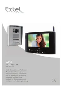
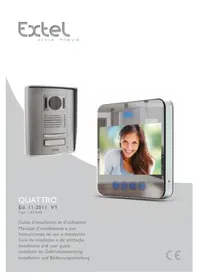
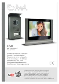
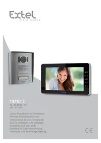
Code - Intercom EXTEL - Free user manual and instructions
Find the device manual for free Code EXTEL in PDF.
Download the instructions for your Intercom in PDF format for free! Find your manual Code - EXTEL and take your electronic device back in hand. On this page are published all the documents necessary for the use of your device. Code by EXTEL.
USER MANUAL Code EXTEL
2 - Intercom panel installation
3 - Connecting an electric strike plate
4 - Connecting a motor drive
2 - Opening the electric strike plate or motor drive
During communication: Starts/ends a call Time screen: starts a call to the second family screen (intercom) In surveillance mode: initiates communication Menu: right arrow or down arrow
Screen off: Enables touch keys and access to the time and then the menu by pressing again Screen off – button flashing: access to photos of visitors when absent Menu: OK (selection button) Call in progress: Takes a photo 1 Protective mirrored façade 2 Camera and infrared LEDs 3 Touchscreen code pad 4 Loudspeaker
Name holder (the transparent plastic can be peeled back to write on the label) 6 Microphone 7 When on: button for calling family 1
Fixing screws for monitor bracket and surface mounting bracket
Fixing screws for intercom panel in mounting bracket 8 Modular power supply
In call or surveillance mode: Opens electric strike plate
Intercom panel and/or secondary monitor communication connector 8 When on: call button 9 When on:button for calling family 2
Dawn-to-dusk cell capable of detecting ambient brightness
Monitor, electric strike plate and gate motor drive connectors (for details, see Fig. 7) Fig. 1 Fig. 2 Fig. 3EN3 Extel - Code - 720309-720311
- The wiring diagrams for the various configurations can be found in: - Fig. 7: 1 family – 1 monitor - Fig. 8: 1 family – 2 monitors - Fig. 9: 2 families – 1 monitor in each (2 monitors in total)
- Do not increase the number of insulating screw joints or connectors on the connecting wire between the intercom panel and the monitor
- In order to avoid the risks of interference and malfunction, do not pass the wire for your videophone through the same sheath as the electrical wires.
- Keep the connecting wire between the intercom panel and the monitor more than 50cm away from any electromagnetic interference (230V cable, Wi-Fi equipment, microwave ovens, etc.).
- You can connect and use the electric door release (not provided) with your intercom panel, with or without mechanical memory.
- To ensure good audio and video quality, it is advised to not use more than 100m of cable between the intercom and the intercom panel. The cable size to be used is shown in Fig. 10 Note: Do not under any circumstances double wires to increase the wire size.
- If a wire is incorrectly connected or disconnected after powering up, the entire system must be disconnected before any intervention. Your gate can be connected to the power supply again once the defective connection has been repaired. Note: if you are testing the product prior to installing it, it is recommended that you place the unit on a flat surface.
2. Loosen the screws to disengage the intercom panel from its mounting case
3. Screw the mounting case to the wall as recommended in Fig. 4.
4. Place a silicone seal between the mounting case and the wall to prevent the infiltration of water.
Do not use an acetic acid-based silicone (smells like vinegar)
5. Connect the wires according to the wiring diagram (Fig. 7)
6. Fit the intercom panel into the mounting case
7. Screw in the intercom panel and replace the magnetic cap plugs
Important: do not expose the camera to direct sunlight or place it facing a reflective surface. Tip: it is recommended that the wires be passed through a sheath to protect them from impacts and weather. - Fig. 5 . Recess mounting an opening of 200 mm (H) x 70 mm (W) x 26 mm (D) is required.
1. Remove the magnetic cap plugs
2. Loosen the screws to disengage the intercom panel from its mounting case
3. Screw the recess case to the wall as recommended in Fig. 4.
4. Place a silicone* seal between the recess case and the wall to prevent the infiltration of water.
- Do not use an acetic acid-based silicone (smells like vinegar)
5. Connect the wires according to the wiring diagram (Fig. 7)
6. Fit the intercom panel into the recess case
7. Screw in the intercom panel and replace the magnetic cap plugsEN4
Directly connect the strike plate or lock wires to terminals 7 and 8 on the back of the panel (no polarity to adhere to). Note that this function is only valid if the screen is on. The unit may buzz at the time of the command. For wiring, refer to the reverse of the panel and the diagram in Fig. 7. Important:
- The maximum distance between the intercom panel and the electric strike plate or electric lock is 50 m maximum. The wire size to be used is 0.75 mm².
- The use of a 12 V/1.1 A max. electric strike plate with WECA mechanical memory (Extel reference 109021 or 109031) or WECA 5001/2 10 SER R1 (reference 150011) is recommended.
4 - CONNECTING A MOTOR DRIVE
Directly connect the strike plate or lock wires to terminals 5 and 6 on the back of the panel (no polarity to adhere to). Note that this function is only valid if the screen is on. The panel provides a "dry" contact connection, without an electric current, to connect to the button for your automated gate. For wiring, refer to the reverse of the panel and the diagram in Fig. 7. Important:
- This function is only valid if the screen is on
- The maximum distance between the intercom panel and the gate motor drive is 50 m maximum. The wire size to be used is 0.75 mm².
- The product has been tested and approved with Thomson "Sésame" or "Swip" gate motor drives which can be found at maisonic.fr The Extel Code videophone is controlled through touch-sensitive keys. The button functions vary depending on the menu accessed. The icons at the bottom of the screen help to guide you as to their use
Screen off: Access to time screen Time screen: intercom panel preview (surveillance mode) Menu : left arrow or up arrow
Duringcommunication: starts/ends a call (where applicable: this action will automatically turn off the second family screen) Time screen: starts a call to the second family screen In surveillance mode: initiates communication Menu: right arrow or down arrow
Screen off: Access to the time and then the menu by pressing again Screen off– button flashing: access to photos of visitors when absent Menu: OK (selection button) Call in progress: takes a photo
Call in progress: opens the electric strike plate
Call in progress: opens the dry contact (gate motor drive) Menu: back/exit (back button to parent menu)
Reset administrator codes and opening code pad
Image adjustment: colour, contrast, brightness 3 Restore videophone factory settings 4 Erase all photos
Setting for presence of a second monitor (enable this option if an additional screen has been added) – default value: no additional screen
The Extel Code keypad is touch screen and backlit.
The default codes are as follows:
- 1 1 1 1 1 1 1 1: administrator code (8 x 1)
- 1 0 0 0: opens the gate motor drive
- 2 0 0 0: opens the electric strike plate By default, the opening pulses are 1 second for the gate motor drive and 1.1 seconds for the electric strike plate. These values can be changed but are compatible with the vast majority of strike plates and motor drives on the market. Consulting the instruction manual for your particular motor drive is recommended however.
2 - OPENING THE ELECTRIC STRIKE PLATE OR MOTOR DRIVE
Only the first digit in the codes for opening the strike plate and the motor drive differ. To open, the codes are as follows:
- 1 + "3 to 7 digit code" + "#" = motor drive opening code
- 2 + "3 to 7 digit code" + "#" = electric strike plate opening code Default:
- 1 0 0 0 # = opens the motor drive
- 2 0 0 0 # = opens the electric strike plate The "3 to 7 digit code" is the same but may be changed in administrator mode.
In settings, you can exit this mode by waiting for 15s or pressing the # key 3 times. If you make a mistake with the code, press the * key before entering the code again.EN7 Extel - Code - 720309-720311
F - INTERCOM PANEL USER MANUAL
Enter the administrator code + " * " (default = 8 x the number 1) 3 x # = Exit BEEP (1.5 s) + all bells flash 3 x THEN all of the bells go off Setting the administrator code " 5 0 " + " * " BEEP (0.25 s) + main bell turns on Time to open motor " 53" + " * " BEEP (0.25 s) + right bell turns on Time to open strike plate " 52 "
BEEP (0.25 s) + left bell goes on Setting the opening code " 5 1 " + " * " BEEP (0.25 s) + left and right bells turn on Enter a new code (4 to 8 digits)
The main bell flashes 3 x, 2 confirmation BEEPs Enter the opening time + " * " ("1" + "*" = 0.1 s) ("99" + " *" = 9.9 s) Right bell flashes 3x 2 confirmation BEEPs Enter the opening time + " * " ("1" + "*" = 0.1 s) ("99" + " *" = 9.9 s) Left bell flashes 3x 2 confirmation BEEPs Enter a code (3 to 7 digits) + " * " Left and right bells flash 3 x 2 confirmation BEEPs New administrator code saved Time to open set Time to open set New code saved “ 1 ”+“ code ” = opens motor "2" + " code" = opens strike plateEN8 Extel - Code - 720309-720311 MONITOR Screen 7" (18cm) colour Video Format PAL/NTSC Resolution 1024 x 600 Dimensions 197(H) x 147(W) x 14(D) mm Power supply 17 V - 1.5 A (provided by power supply unit) Door plate Camera CMOS 700 VTL Power supply 13 V – 200 mA max. Angle 95° (H) / 48° (V) Night vision Up to 1m Dimensions 182(H) x 61(W) x 32(D) mm Weather protection IP54
- The warranty is void if parts have been dismantled. Clean the outside with a soft, dry cloth only. Before cleaning, disconnect or switch off the video surveillance system. NOTE
- Do not use any gasoline or carboxylic acid, alcohol or similar treatment. In addition to damaging your device, the fumes are also hazardous to your health and are explosive.
- Do not use any tool that can conduct voltage (wire brush, sharp tool, etc.) for cleaning. If necessary, consult our technical website: www.cfi-extel.com Latest version of the downloadable instructions in colour: www.cfi-extel.com WARRANTY CONDITIONS
- This product is guaranteed for parts and labour in our workshops.
- The warranty does not cover: consumables (batteries, etc.) and damage caused by misuse, improper use, improper installation, external intervention, damage due to physical or electrical shocks, dropping or atmospheric phenomena.
- Do not open the device as doing so will void the warranty.
- Clean with a soft cloth only, no solvents. The warranty is void if parts have been dismantled. Clean the outside with a soft dry cloth only. Before cleaning, disconnect the equipment or switch it off at the mains.
- The receipt or invoice is proof of purchase date.EN9 Extel - Code - 720309-720311
I - SAFETY INSTRUCTIONS
- Please read the user manual carefully before installing or using this product
- If you are installing this product for someone else, remember to leave the manual or a copy of it with the end user Warning
- The various items should be dismantled by an authorised technician only. Safety measures
- For operation of this system in complete safety, it is essential that the installers, users, and technicians follow all of the safety procedures described in this manual.
- Specific warnings and warning symbols are given for items if necessary.
- The product must be set up according to the applicable standards in the country where it is installed (NFC15- 100 for France).
- Damage caused by failing to adhere to the manual nullifies the warranty. We will not accept liability for damage resulting from non-compliance! We will not accept liability for any harm to goods or people caused by improper handling or failure to adhere to safety instructions.
- This product was manufactured in total compliance with safety guidelines. To maintain this status and provide for the best possible conditions of usage, the user must adhere to the safety instructions and warnings in this manual. This symbol indicates a risk of electrical shock or short-circuiting. - Only use this product with electrical current in the following ranges: 100-240volts and 50-60 hertz. Never try to use this device with an electrical current outside of these ranges. - Verify that all of the electrical connections of the system are consistent with the usage instructions. - In commercial establishments, be sure to adhere to accident prevention rules for electrical installations. - For schools, training equipment, workshops, etc., the presence of qualified personnel is needed to monitor operation of the electronic devices. - Adhere to the usage instructions for other devices connected to the system. - Contact a person with experience if you are unsure about how to operate the system or about the safety of devices. - Never plug in or unplug electrical devices with wet hands. - When installing this product, verify that the power wires are not at risk of being damaged. - Never replace damaged electrical wires yourself! If an electrical wire is damaged, remove it and ask for help from a person with experience. Warning This logo denotes that devices which are no longer in use must not be disposed of as household waste. They are likely to contain hazardous substances that are dangerous to both health and the environment. Return the equipment to your local distributor or use the recycling collection service provided by your local council. Pour en savoir plus : www.quefairedemesdechets.frNL1 Extel - Code - 720309-720311 INHOUDSOPGAVE
ManualGo.com