Levo JSV742N2 - Intercom EXTEL - Free user manual and instructions
Find the device manual for free Levo JSV742N2 EXTEL in PDF.
Document temporarily unavailable
The manual is currently being transferred to our new server. It will be accessible again in a few hours. Thank you for your patience.
| Product type | Color video intercom |
| Brand | EXTEL |
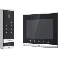
| Model | Levo JSV742N2 |
| Monitor dimensions (W × D × H) | 216 × 152.8 × 13.3 mm |
| Screen | 7 inch (18 cm) capacitive touch, resolution 800 × 480 |
| Monitor power supply | 17 V DC via adapter 100-240 V~, 50/60 Hz, 1.5 A |
| Door station dimensions (with visor) | 186 × 100 × 45 mm |
| Door station protection rating | IP44 |
| Door station camera | Color CMOS 1/4 inch, 700 TVL, angle 102°H × 75°V, sensitivity 0.5 Lux |
| Internal memory | 90 MB |
| External storage | SD card (max 32 GB, no micro SD + adapter) |
| Wiring type | 2 wires (0.6 mm² up to 25 m, 1.5 mm² from 25 to 100 m) |
| Functions | Intercom, video call, electric strike/lock control, gate motor, photo/video recording |
| Operating temperature (door station) | -15°C to +50°C |
| Maintenance | Soft cloth, no solvent, disconnect before cleaning |
| Warranty | Parts and labor in our workshops (excluding consumables, misuse, impact) |
| Options | Strikes, locks, Extel motors, additional CAM LEVO camera (IP65) |
| Technical support | 0 892 350 069 (€0.35/min + call price), www.cfi-extel.com |
| Automatic standby | Yes (10 s on home page, 35 s on settings/multimedia) |
| Number of wires for connection | 2 wires for all functions |
Frequently Asked Questions - Levo JSV742N2 EXTEL
User questions about Levo JSV742N2 EXTEL
0 question about this device. Answer the ones you know or ask your own.
Ask a new question about this device
Download the instructions for your Intercom in PDF format for free! Find your manual Levo JSV742N2 - EXTEL and take your electronic device back in hand. On this page are published all the documents necessary for the use of your device. Levo JSV742N2 by EXTEL.