Weva DB9035E - Intercom EXTEL - Free user manual and instructions
Find the device manual for free Weva DB9035E EXTEL in PDF.
| Product type | Wireless video intercom |
| Brand | Extel |
| Model | Weva DB9035E |
| Monitor dimensions (W × H × D) | 220 × 143 × 35 mm |
| Street panel dimensions (W × H × D) | 150 × 115 × 42 mm |
| Monitor power supply | AC adapter 230 V / 5 V === |
| Street panel power supply | 4 LR20 batteries (1.5 V) or low voltage 12/24 V - |
| Monitor consumption | 900 mA |
| Radio frequency | 2,402 - 2,454 GHz (GFSK) |
| Open field range | Up to 300 m |
| Screen type | Color screen 18 cm (diagonal) |
| Night vision | Yes (IR LED) |
| SD card recording | Up to 32 GB max., 1 GB min. |
| Video recording format | .avi |
| Hands-free function | Yes |
| Electric strike/lock control | Yes (pulse < 1 s) |
| Gate automation control | Yes (pulse 2 s) |
| Operating temperature (monitor) | -10 °C to +40 °C |
| Operating temperature (camera) | -10 °C to +45 °C |
| Camera protection rating | IP44 |
| Maintenance and cleaning | Soft dry cloth, do not use solvents or abrasive products |
| Safety | Follow installation instructions and specified supply voltages |
| Spare parts and repairability | Contact Extel technical service (hotline 0892-35-00-69) |
| General information | Wireless video door phone, compatible with Extel strikes and motors |
Frequently Asked Questions - Weva DB9035E EXTEL
User questions about Weva DB9035E EXTEL
0 question about this device. Answer the ones you know or ask your own.
Ask a new question about this device
Download the instructions for your Intercom in PDF format for free! Find your manual Weva DB9035E - EXTEL and take your electronic device back in hand. On this page are published all the documents necessary for the use of your device. Weva DB9035E by EXTEL.
USER MANUAL Weva DB9035E EXTEL
Installation and user guide
b. Monitor (MN WEVA)
Alimentazioni
d. Telecamera (PL WEVA)
10 OPZIONI p.9
ASSISTENZA TECHNICA / GARANZIA
12 DISPOSIZIONI DI SICUREZZA .p.10
I. DISPOSITIONI DI SICUREZZA
Important!
b. Monitor (MN WEVA)
b. Monitor (MN WEVA)
- Pantalla: 18 cm de diagonal
- Alimentación del monitor: SV
- Consumo: 900 mA
- Dimensiones: 220 × 143 × 35( mm)
- Temperatura de uso: -10°C a +40°C aproximadamente.
c. Alimentación
Adaptador 230V5V4A
b. Monitor (MN WEVA)
c. Alimentacao
Camarra(PL
WEVA)
10 OPcOs p.9
II ASSISTÉNCI TÉCNICA / GARANTIA p.9
12 INSTRUÇOÉS DE SEGURANCA .p.10
I. INSTRUÇÉS DE SEGURANÇA
Importante!
b. Monitor (MN WEVA)
b. Outdoor station, exterior camera
4 INSTALLING. p3
a. Installing of outdoor station (camera) & control box board
b. Installing of monitor
5 DIRECTIONS FOR USE p.5
6 SCREEN ICON p.6
7 MENU p.6
8 APPLICATIONS p.7
a. Camera Setup
b. Recorder Setup
c. Event List
d. System Setup
9 TECHNICAL SPECIFICATIONS. p.8
a. Technical specifications
b. Monitor (MNWEVA)
c. Power supply
d. Camera (PL WEVA)
10 OPTIONS p.9
11 TECHNICAL ASSISTANCE - GUARANTEE. p.9
12 SAFETY INSTRUCTIONS .p.10
I. SAFETY INSTRUCTIONS
Important!
- Please read the user manual thoroughly before installing or using this product.
If you install this product for other people, please give the manual or a copy to the end user.
Warning:
The different elements can only be dismantled by an authorised technician.
Safety instructions :
- To safely use this system, it is essential the fitters, users and technicians follow the safety procedures described in this manual.
- Specific warnings and caution symbols are indicated on the elements if necessary.
Warning:
- The user of this system is responsible for checking whether the surveillance is compliant with the law in force in the country of use.
- Even if they are digital, the cameras are subject to interference of wireless phones, microwave ovens and other wireless appliances operating on 2.4 GHz (WiFi for example).
- Keep the system at more than 3m of the appliances during installation and use.
N.B.:
- All the active electronic components are sensitive to human body electrostatic discharges. Always drain the static electricity from your body (such as by touching a finger to one of the battery contacts - red wire or black wire - in the box) before servicing them.
The warranty does not cover any damage resulting from failure to comply with these instructions.
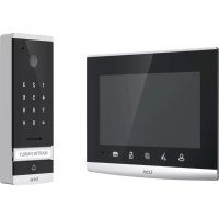
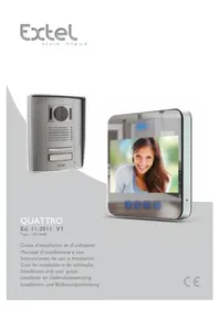
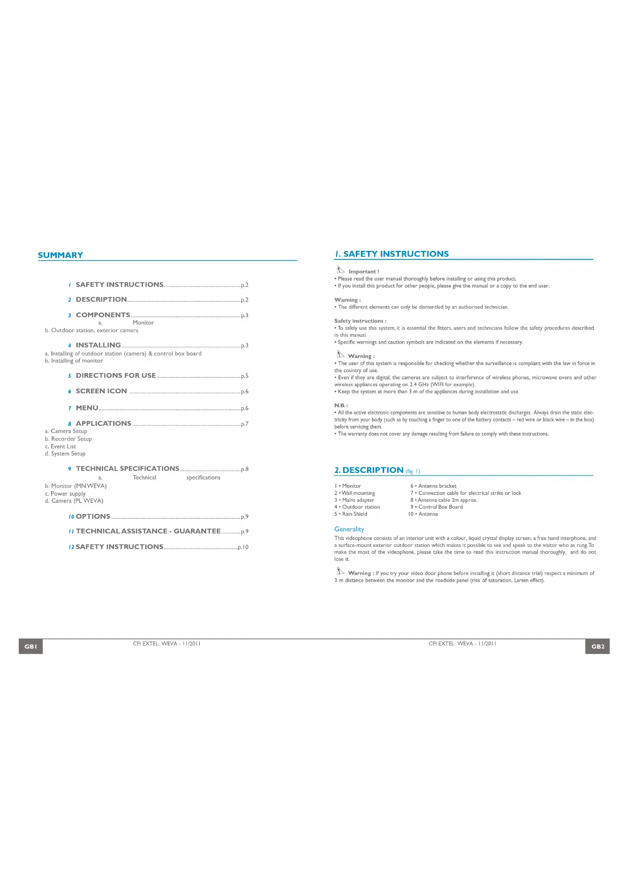
2.DESCRIPTION (fig.1)
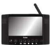
I·Monitor
2·Wallmounting
3·Mains adapter
4·Outdoor station
5·RainShield
6 - Antenna bracket
7. Connection cable for electrical strike or lock
8 Antenna cable 2m approx.
9. Control Box Board
Generality
This videophone consists of an interior unit with a colour, liquid crystal display screen, a free hand interphone, and a surface-mount exterior outdoor station which makes it possible to see and speak to the visitor who as rung.To make the most of the videophone, please take the time to read this instruction manual thoroughly, and do not lose it.
Warning: If you try your video door phone before installing it (short distance trial) respect a minimum of 3 m distance between the monitor and the roadside panel (risk of saturation, Larson effect).
3. COMPONENTS
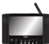
a. Monitor (fig. 2)
I. Indicator: Recording in progress (flashes)
2. Unread recording indicator
3. Plug for audio line // Start-up
4. "DEL" function on menu // Monitor access
5. Control of a strike/lock and/or of an automatic gate opener (valid only if the screen is switched on) // validation @OK
a. A 2-second pulse for the control of an automatic gate opener.
b. A short press (less than 1 second) for the control of a strike or an electric lock.
6. Menu Access // EXIT
7. Lower cursor // manual recording
8. Right cursor // Volume adjustment
9. Microphone for the conversation
10.Antenna
11. SD card slot (32 Go Max. - 1 Go Min)
12. Connector by the 5V^ plug of the adapter (adapter to connect to an installation compliant with standards in force : NFC 15 100 in France)
13. Bracket to unfold
b. Outdoor station, exterior camera (fig. 3)
I. IR LED, night vision (light invisible to the naked eye).
2. Lens of C-MOS video camera with automatic iris (adjustable from back of video camera).
3. Loudspeaker: for communicating from outside building
4. Call button: when this button is pressed the name-plate lights up and the chime is heard inside and outside the building.
5. Nameplate and LED lights:
- if the electronic cabinet is battery-powered the indicator only turns on after a call if the low-light vision is too important.
- if the electronic cabinet is powered external (12 ou 24 V~/min), the indicator only turns on when the low-light
vision is too important - gently lift up the protective plastic cover with a small screwdriver and slide the card in the slot.
- Microphone: for communicating with the person inside.
4. INSTALLING
Important : This video door phone has a range of 300 m in free field. The actual ranges may be shorter depending on the quantity and type of obstacles between or beside the units. It is therefore essential to test all system components before installing them in order to determine the best locations for the roadside panel and the monitor.
a. Installing of cordless indoor unit
Composition: -a roadside panel
- an electronic box housing the radio transceiver and the batteries (not supplied).
- a rain shield
-an antenna
Important : Do not point the video camera directly at the sun or at reflecting surfaces.
Tip: we recommend passing the cables through a protective sleeve to shield them from impacts and the weather.
- Installing the control box board (fig.5)
Use the 6-conductor cable to connect the box and the intercom panel, ensuring the colours match (fig.8). Insert 4 LR20 batteries into the electronic box to test the radio range. The antenna as far away as possible from all metal surfaces, sources of interference and obstacles between the box and your home, (in particular, no leaves or branches should touch it). For best results, it should also be placed high enough (approx. 1 & m above ground level) and be vertical.
N.B.: If the transmission is of insufficient quality, use the 2m cable supplied to find a better position for the antenna.
Once the ideal location has been found, permanently mount the equipment:
Once you have found the ideal location :
1- Remove the cover from the box by unscrewing the 6 cross-head screws (H) (fig. 5).
Warning : do not directly touch the electronic circuitry ( see comment chapter safety instruction : Important - p3)
2- Fasten the box with two screws (J) at the top and bottom (fig. 6). The antenna is at the top right.
3* Remember to route the connecting cable for the roadside panel through the hole in the post first and 2 wires (F) for the cabinet/electric strike link (it is thus necessary to bore the pillar or the wall consequently). The connection (F) must to connect the other two wires to the lock or electric strike plate and on the connection «LOCK» of control box.
NB.: Do not install an antenna other than the original one supplied

Warning: Never insert the batteries before installation is completely finished.
- Installing the roadside panel (fig.6/7/8)
Tip: we recommend running the cables (for the roadside panel and the electric strike plate) through a conduit to protect them from impacts and the elements. To avoid oxidation and poor contacts, do not trim the excess from the 6-conductor cable. Instead, wind it around itself between the post and the electronic box.
1- Remove the cross-head screw (A)
2* Tip the roadside panel (B) toward the front and dislodge it from the bottom.
3. Using the 3 screws (K), mount the box (C) flush with the wall so that the slot (D) is facing the cable (E).
4- Fit a silicone seal behind the Rain shield (C) to protect it from water running down the wall.
5 Pass the connecting cable
6 Connect the 6 wires (E) to the back of the roadside panel
7 Check the orientation of the camera (G) (fig. 8).
VIDEO ( yellow ) GND ( black ) SPK ( brown ) MIC ( white ) KEY (green) VCC ( red )
8- Put the roadside panel back in place and fasten with the screw (A).
To complete installation of the roadside panel, open the battery compartment on the electronic box, box and insert four 1.5 V alkaline LR20 batteries. Be sure to follow the polarity markings. Close the battery compartment and put the electronic box cover back in place with the 6 cross-head screws (H). Take care not to pinch or damage the seal. You can use a low voltage supply power source, coming from a type WETR I4602 SER.R1 transformer or from an automatic gate opener (12 ou 24 V-/-). It should be connected on the terminals ≈ and ± of the electronic cabinet. In the case of direct voltage () pay attention to the polarity +/- .
Warning: If you do not use the batterie but by 12/24 V source (automatic opener) to connect as indicated Fig.9
If you are using a 12/24 V- power source, the batteries must be removed.
Do not use rechargeable batteries.
b. Installing of monitor (fig.4)
Install the monitor at approximately 1,60 m above the ground (for optimum reception conditions).
For installing the monitor, choose a location away from reinforced concrete walls, mirrors, metallic shelves, etc...
Keep the monitor away from all appliances creating strong electrical interference.
Any strong electrical environment may cause disturbances and interferes with the use (WIFI in particular).
For table-mounting, unfold the foot (A) and install the monitor on a stable surface.
Connecting the monitor:
-
Connect the cord of the 5 V-adaptor to the "power supply" plug of the monitor. (B)
-
Plug the adaptor into a 230 V mains socket.

Warning: Only place the monitor on stable and hard surfaces.
5. DIRECTIONS FOR USE
The monitor must be in standby mode, the indicator turned blue. (this mode is activated with 0). When the Call button is pressed on the roadside panel the monitor will ring for approximately 8 seconds. At the same time, a tone will sound on the roadside panel to confirm that the call has been sent. You have approximately 30 seconds to answer the call. At this time, the electronic box enters standby mode. If the electronic cabinet is powered by a 12 or 24V - m source, you can force the communication with the roadside panel pressing the key. If the electronic cabinet is battery-powered the call is lost.
The conversation is established during a call pressing the key. You can increase the volume by pressing the key
The system will time out after 30 seconds. To extend this time for an additional 30 seconds, press the Answer buttons during a call. You can end the communication pressing or 3 seconds.
1- Recording from the monitor: (SD card required)
-
If the "visiting record" option (see b.p.7) is not activated, recording can be started/stopped by pressing on
-
If the "visiting record" option is activated, recording starts automatically when a call is made from the intercom panel.
-
If used with an electric strike plate (or electric lock)
The electric strike plate can be opened only when communicating with a caller (all the time if the electronic cabinet is powered by external AC/DC supply). To open it, press briefly tha key, then press briefly the 1 (sec.).
Caution : One single opening control is possible per call under operation on battery.
N.B.: The strike plate or lock must be «one pulse type» in order for the door/gate to be opened.
3- If used with an automatic opener :
Caution : An automatic gate opener may be operated via remote control If the electronic cabinet is powered by external AC/DC supply. To open it, press the key for 3 seconds during a call.
- If no call is in progress, press on then on foal seconds.
Reminder :The reception of a call on the monitor is only possible if it is in standby mode and paired with the roadside panel (see chapter Pairing).
Important : The handset has a free-field range of up to approximately 300 metres. This range may be considerably reduced by certain environmental factors (nearby radio interference, etc.)
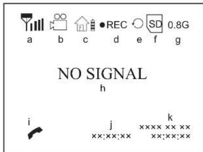
6. SCREEN ICON
a. Signal indicator
b. Visiting record indicator (On)
c. Outdoor unit battery indicator
Full Battery (yellow)
- Low Battery (red/twinkling)
d. Manual recording
e. 品 :no SD card
F:Full SD card
Err.:SD card error
SD card locked
SD card overwrite
f. SD card indicator
g. SD card storage room indicator
h. No signal indicator
i. Answering indicator
j. Record time
k. System time
7. MENU
Press ESC key for 2 seconds to display the following screens (and to scroll, OK to validate).
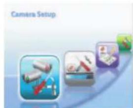
a. Camera Setup
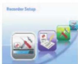
b. Recorder Setup

c. Event List
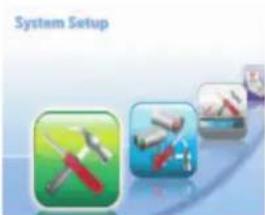
d. System Setup
8. APPLICATIONS
a. Camera
Camera Brightness :
Press OK to enter Camera Brightness adjustment bar.
- Press > to adjust brightness, press OK to confirm and exit.
2- Pairing
Press V , then press OK to enter Pairing menu, system will count down 60 seconds (fig.5-1) in the control box within 60 seconds.Once pairing completed, it will display image of door unit.
N.B.: It strongly recommended to pair with door unit before installation.
Press ESC to exit.
1.

2·
b. Recorder Setup (the recorded sequences are in file «avi»)
Visiting record : Use to set ON/OFF
N.B.: If no answering, answering unit will record 30 seconds and then screen will be turned off automatically.
The indicator will signal an unread recording
2-SD card format:
Press OK to enter SD card format
- Sele & press OK to format
N.B.: Make sure SD card is unlocked (Comments p11). For first time use, it's recommended to format SD card
3-SD card overwrite : If the card is full, this mode is used to select permanent overwriting of the first recordings
by the most recent ones
Use to select ON/OFF, press OK to save
Press ESC to exit.
1·
2·
3·
c. Event List
In view mode:
Press OK to enter record folder.
Continue to press OK to play/pause file.
2 Inplaying mode:
Pre to adjust the volume
Pre to fast backward 2x, 4x, 8x &16x
Press ESC to stop and exit
3 In delecting mode:
Press DEL to enter deletion mode
- URE to delete the selected file or delete all
Press OK and sel then press OK to delete
Press ESC to exit.
d. System setup
Time setting:
- Press to select the item desired:Year/Month/Day/Hours/Minutes.
Pre to change the system clock.
Press OK to confirm the settings.
2 Software version : it displays system version of answering unit & door unit.
3- TV format: Use to select TV systeme between NTSC & PAL (recommended).
4 Factory default: Press OK to enter in the menu, select 0 then press OK
Press ESC to exit.
1
3·
3
2·
4
9. TECHNICAL SPECIFICATIONS
a. Technicals specifications :
RF specification
Frequency radio 2,402-2,454 GHz
-GFSK (Frequency Hopping Spread Spectrum) numerical modulation
-Anti-interference
-Chainbandwidth:2MHz
b. Monitor (MN WEVA)
-Reference:810268
Screen: 18 cm in diagonal
Monitor power supply: 5V
- Power consumption: 900 mA
- Dimensions: 220 × 143 × 35( mm)
- Operating temperature: -10°C to +40° approx.
c. Power supply
Adaptor 230 V-15 V-A
If the power supply cable has to be cut, ensure that the colour coding of the wires is maintained whenreconnecting.
d. Camera (PL WEVA)
-Reference:820659
- Dimensions : 150 x 115 x 42 mm
- Operating temperature: -10°C to +45° approx.
- Camera: C-MOS
-Lens:H:62° V:42°
Light Sensibility < 8 lux
Protection of the cameras: IP 44


10 OPTIONS
All Extel electric catches
All ExteIelectric locks
All Extel mechanisms
WE811BIS
II. TECHNICAL ASSISTANCE - GUARANTEE
| Problems Possible Causes Remedies | |
| • No function •No power supply • Check the connection of the adaptor • Check the battery of the monitor is properly charged (blue led ⑧) • Check the voltage of the batteries in the electronic cabinet | |
| • The roadside panel rings but not the monitor | • Pairing problem • Range problem |
| • No sound outside and inside | • Hole of the microhone blocked by an insect |
| • Poor Image • Configuration | problem • Go to the menu and check the video format (p 8) |
| • Impossible to record on SD card | • Protection problem • Check the card is not locked or full (see screen indications p 6-e) |
If necessary, our technical website is at your disposal www.cfi-extel.com
HOTLINE:0892-35-00-69(0,337@tcc/min)
Last version of the downloadable manual in color on : www.cfi-extel.com
GUARANTEE CONDITIONS : This device is guaranteed for labour and parts in our premises.
The guarantee does not cover the consumables (batteries, etc.) and the damages caused by: misuse, improper installation, external intervention, deterioration by mechanical or electrical shock, fall or atmospheric phenomenon. a News One the asscss on the gurante will be inlaid
For return in SAV, protect the screen to prevent scratching.
- Only ever clean with a soft cloth; never use solvents. Before cleaning, disconnect and switch off the system.
Caution: Do not use any acid or alcohol based or other similar cleaning product or solvent. You may damage the appliance and the vapours are explosive and dangerous for your health.
Do not use any tool which can be voltage conductor (metallic brush, sharp tool...or other) for cleaning.
The sales slip or the invoice is required as proof of purchase date.
12. SAFETY INSTRUCTIONS
The damages caused by the non-compliance to the manual lead to the expiration of the warranty. We will not assume any responsibility for the resulting damage!
We will not assume any responsibility concerning any damage, to the goods or people, caused by improper handling or by non compliance with the safety instructions.
This product has been manufactured in compliance with safety instructions. In order to keep this status and ensuring the best operation of the product, the user must respect the safety instructions and warnings contained in this manual.
The user of this system is responsible for checking whether the video surveillance is compliant with the law in force in the country of use.

: This symbol indicates a risk of electric shock or a risk of short circuit
- You should only use this product within a voltage range between: 100-240 Volts and 50-60 hertz. Never intend to use this product with a different voltage.
- Make sure all electrical connections of the system are compliant with instructions of use.
- In commercial establishments, make sure to respect the rules for preventing accidents with the electrical installations.
- In schools, training institutions and workshops... the presence of a qualified personnel is necessary to control the operation of electronic appliances.
- Respect the instructions of use of other appliances connected to the system. (video recorder, TV, PC for example)
- Please contact an experienced person in case of doubt concerning the mode of operation or the safety of the appliances.
- Never connect or disconnect the electrical appliances with wet hands.
- When installing this product, check the power supply cables are not liable to be damaged.
- Never replace the damaged electrical cables by yourself. In this case, remove them and contact an experienced person.
WARNING
Informs the user about the presence of Important Instructions concerning the use and the maintenance (repair) in the documentation supplied with the appliance.

Informs the user about the presence of "hazardous voltages" non-isolated inside the housing of the product, being sufficiently high to represent a risk of electrocution for people.
INHOU
VEILIGHEIDSINSTRUCTIES. p.2
2 BESCHRIJVING p.2
3 OnderdeLEIN p.3
2. BESCHRIJVING (fig.1)
b. Monitor (MN WEVA)
b. Monitor (MN WEVA)
c. Kamera (PL WEVA)
10 OPTIONEN p.9
11 KUNDENDIENST - GARANTIE. p.9
12 SICHERHEITSEMPFHLUNGEN p.10
b. Monitor (MN WEVA)
Article 3.2: (right use of the radio electric spectrum in order to avoid prejudicial interferences)
EN300328:V1.7.1:2006
Declarsthatalltherquiredradio testshavebeendone.
Art. 3.3 : (eventuel) / (eventuel) / (eventuale) / (eventual) / (eventual) / (eventuel) / (eventual)
Date Datal Data Dala Data Datal 11/2010 (08 NOV 2010)
Signature of titre | Handfekening en functie | Firma e titolo | Firma y cargo | Assinatura e titulo | Unterschrift
und Funktion / Signature and title :
M. Xavier BAILO (directeur général)
personne autorisee bevoegd persono autorizzata persona aut orizada representante legal
autorisierte Person / authorized p

CFI Z.I.deFetan
01600 TRÉVOUX - France
TEL: +33,474,089,600
S.A.S. au capital de-1 000 000 €
A. A. du capital 100000000
11 SIRET:BOORG 38402489900021

WEVA
Compliant with R&TTE, usable in the EEC