MEMO 2 - Intercom EXTEL - Free user manual and instructions
Find the device manual for free MEMO 2 EXTEL in PDF.
Document temporarily unavailable
The manual is currently being transferred to our new server. It will be accessible again in a few hours. Thank you for your patience.
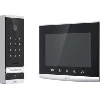
| Product type | Video door phone with color screen and outdoor camera |
| Brand / Model | Extel MEMO 2 |
| Monitor dimensions | 197 × 117 × 23 mm |
| Street panel dimensions (with visor) | 160 × 120 × 30 mm |
| Power supply | 100-240 V~, 50/60 Hz (adaptor 17 V~, 1.5 A) |
| Power consumption | 5.1 W |
| Screen type | 7-inch TFT color screen (18 cm) |
| Screen resolution | 800 × 480 pixels |
| Camera resolution | 640 × 480 pixels CMOS color |
| Viewing angle | Horizontal 53°, Vertical 66° |
| Camera sensitivity | 3 Lux |
| Internal memory | 107 MB |
| External storage | SD card up to 32 GB (not included) |
| Number of ringtones | 9 adjustable melodies |
| Main functions | Audio/video communication, door release (strike/lock), automation control (gate), monitoring, photo/video recording, multimedia (photo, music, video) |
| Protection rating (street panel) | IP44 |
| Operating temperature | -10°C to +45°C |
| Maintenance | Clean with a soft dry cloth. Do not use solvents. |
| Safety | Dangerous voltage inside. Installation and repair by a qualified technician. |
| Warranty | Parts and labor in our workshops. Exclusions: consumables, incorrect use. |
| Compatible options | Extel strikes, locks and gate openers |
| Technical support | Hotline 0892-35-00-69 (€0.337 incl. tax/min) - www.cfi-extel.com |
Frequently Asked Questions - MEMO 2 EXTEL
User questions about MEMO 2 EXTEL
0 question about this device. Answer the ones you know or ask your own.
Ask a new question about this device
Download the instructions for your Intercom in PDF format for free! Find your manual MEMO 2 - EXTEL and take your electronic device back in hand. On this page are published all the documents necessary for the use of your device. MEMO 2 by EXTEL.