STHL 2000 B2 - Electric heater SILVERCREST - Free user manual and instructions
Find the device manual for free STHL 2000 B2 SILVERCREST in PDF.
| Product type | Ceramic fan heater tower |
| Brand | SilverCrest |
| Model | STHL 2000 B2 |
| Rated power | 2000 W |
| Heat levels | 1200 W (level 1) and 2000 W (level 2) |
| Supply voltage | 220–240 V ~, 50–60 Hz |
| Protection class | II |
| Adjustable temperature range | 15 °C to 40 °C |
| Timer | 24 hours (adjustable in 1-hour increments) |
| Power cord length | 1.8 m |
| Oscillation function | Yes (side-to-side sweeping) |
| Remote control | Yes (CR2025 battery included) |
| Display | LED display of room temperature and settings |
| Overheat protection | Yes (automatic shut-off of heating element) |
| Tip-over protection | Yes (automatic shut-off if tilted) |
| Assembly required | Screw-on base (4 screws supplied) |
| Dimensions (approx.) | Height ~65 cm, width ~25 cm, depth ~25 cm |
| Weight (approx.) | Approx. 3.5 kg |
| Intended use | Supplementary heating for well-insulated rooms |
| Maintenance and cleaning | Unplug, let cool, wipe with a damp cloth, vacuum ventilation grilles |
| Batteries | Remote control: CR2025 button cell (3V lithium) |
| Warranty | 3 years (manufacturer warranty ROWI Germany GmbH) |
| Repairability | Contact customer service (toll-free number +800 7694 7694) |
Frequently Asked Questions - STHL 2000 B2 SILVERCREST
User questions about STHL 2000 B2 SILVERCREST
0 question about this device. Answer the ones you know or ask your own.
Ask a new question about this device
Download the instructions for your Electric heater in PDF format for free! Find your manual STHL 2000 B2 - SILVERCREST and take your electronic device back in hand. On this page are published all the documents necessary for the use of your device. STHL 2000 B2 by SILVERCREST.
USER MANUAL STHL 2000 B2 SILVERCREST
PDF ONLINE
www.lidl-service.com
GB IE CYNI MT
CERAMIC TOWER HEATER
Operating and Safety Instructions
This product is only suitable for well insulated spaces or occasional use.
FR BECH
RADIATEUR SOUFFLANT TOUR CÉRAMIQUE
Before reading, fold out the page with the images and familiarise yourself with all the features of the device.
DE AT CH
GB/IE/NI/CY/MT Operation and Safety Instructions Page 5
1. Introduction 6
1.1 Intended use....6
1.2 Scope of delivery 6
1.3 Features....6
1.4 Technical data....6
2. Safety indications 8
2.1 General safety indications: Safety of electrical appliances for home use...8.....
2.2 Specific safety indications: Special requirements for room heating appliances...9.....
2.3 Information about batteries..10....
3. Before starting up ...12....
3.1 Mounting the stand..12....
3.2 Setting up the unit...12....
3.3 Remote control: Inserting/changing the battery.... 12
4. Start-up 13
4.1 Standby mode 13
4.2 Ventilator-mode 13
4.3 Heating level setting (heating mode) 13
4.4 Switching off the unit 13
4.5 Oscillation function 13
4.6 Temperature setting 13
4.7 Timer setting 14
5. Protective devices for the appliance 14
5.1 Overheating protection 14
5.2 Tip-over protection....14
6. Maintenance, cleaning and storage 15
7. Disposal 15
8. EU conformity 15
9. ROWI Germany GmbH Warranty 15
10. Service 17
CERAMIC TOWER HEATER STHL 2000 B2
1. Introduction
Congratulations on purchasing your new appliance. You have decided in favour of a high-quality product. The operating instructions are part of this product. They contain important information regarding the safety, use and disposal. Familiarise yourself with all the operating and safety indications prior to using the product. Only use the product as described and for the specified areas of use. If you pass the product on to third parties, hand out all the documents too.
1.1 Intended use
This product is only suitable for well-insulated rooms or occasional use. The appliance is not intended for use in rooms in which special conditions prevail, e.g. a corrosive or explosive atmosphere (dust, vapour or gas). Do not use this appliance outdoors. Only use the unit with the stand mounted. Every further use or change to the appliance is viewed as not in accordance with its intended use and involves considerable accident risks. We assume no liability for damages arising from improper use. The heater blower is only determined for use as supplementary heating and exclusively for private use.
1.2 Scope of delivery
1 Ceramic tower heater STHL 2000 B2
1 Remote control (including coin cell)
1 Stand (2 parts)
4 Screws
1 Set of operating instructions
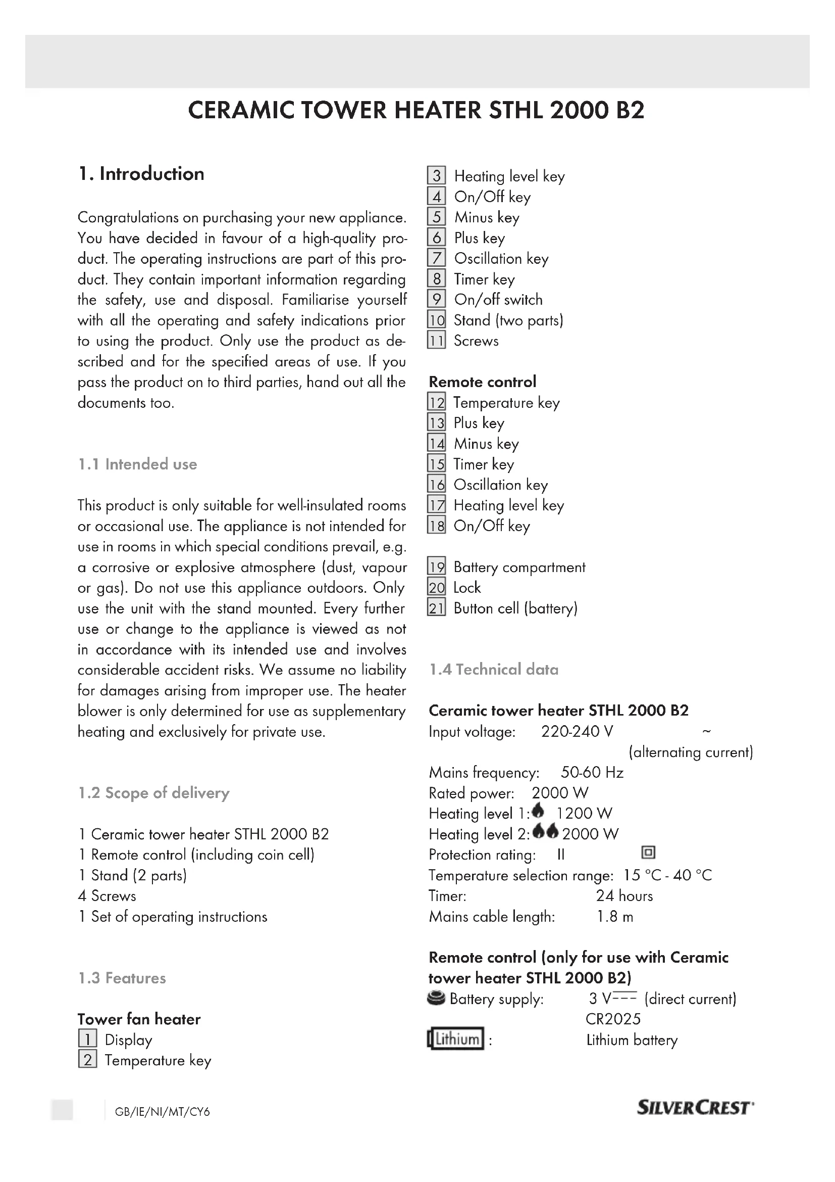
1.3 Features
Tower fan heater
1 Display
2 Temperature key
3 Heating level key
4 On/Off key
5 Minus key
6 Plus key
7 Oscillation key
8 Timer key
9 On/off switch
10 Stand (two parts)
11 Screws
Remote control
12 Temperature key
13 Plus key
14 Minus key
15 Timer key
16 Oscillation key
17 Heating level key
18 On/Off key
19 Battery compartment
20 Lock
21 Button cell (battery)
1.4 Technical data
Ceramic tower heater STHL 2000 B2
Input voltage: 220-240 V \~ (alternating current)
Mains frequency: 50-60 Hz
Rated power: 2000 W
Heating level 1: ♦ 1200 W
Heating level 2: ◆ ◆ 2000 W
Protection rating: II

Temperature selection range: 15 °C - 40 °C
Timer: 24 hours
Mains cable length: 1.8 m
Remote control (only for use with Ceramic tower heater STHL 2000 B2)
Battery supply: 3 V--- (direct current) CR2025
Lithium : Lithium battery
Information requirements for electric local space heaters
Model identifier(s): STHL 2000 B2
Item Symbol Value Unit
Heat output
| Nominal heat output P | nom | 2.0 kW |
| Minimum heat output (indicative) | P_min | 1.2 kW |
| Maximum continuous heat output | P_max,c | 2.0 kW |
Auxiliary electricity consumption
| At nominal heat output el _max | 0.000 kW |
| At minimum heat output el _min | 0.000 kW |
| In standby mode el _SB | 0.000 kW |
Item Unit
Type of heat input, for electric storage local space heaters only (select one)
manual heat charge control, with integrated thermostat [no]
manual heat charge control with room and/or outdoor temperature feedback [no]
electronic heat charge control with room and/or outdoor temperature feedback [no]
fan assisted heat output [no]
Type of heat output/room temperature control (select one)
single stage heat output and no room temperature control [no]
Two or more manual stages, no room temperature control [no]
with mechanic thermostat room temperature control [no]
with electronic room temperature control [yes]
electronic room temperature control plus day timer [no]
electronic room temperature control plus week timer [no]
Other control options (multiple selections possible)
room temperature control, with presence detection [no]
room temperature control, with open window detection [no]
with distance control option [no]
with adaptive start control [no]
with working time limitation [yes]
with black bulb sensor [no]
ROWI Germany GmbH
2. Safety indications
Read all the safety indications and instructions.
Failure to adhere to the safety indications and instructions may cause serious injuries and/or property damages.
Please keep all the safety indications and instructions for future use.
2.1 General safety indications:
Safety of electrical appliances for home use
This appliance can be used by children of 8 years and more as well as by persons with reduced physical, sensory or mental abilities or lacking experience and knowledge, if they are supervised or are instructed in the safe use of the appliance and understand the ensuing dangers. Children may not play with the appliance. The cleaning and maintenance of the appliance by the user may not be carried out by children not under supervision.
- No measures need to be taken by the user to set the product to 50 or 60 Hz or 220 or 240 V. The product adjusts automatically to the correct frequency or voltage.
If the supply cable for this appliance is damaged, it must be replaced by the manufacturer or his customer service or a similarly qualified person in order to avoid any dangers.
2.2 Specific safety indications:
Special requirements for room heating appliances
WARNING! Do not cover!
To avoid the heater overheating, it must not be covered.
- The heater may not be placed directly beneath a wall mains socket.
- Do not use this heater in the direct vicinity of a bathtub, a shower or a swimming pool.
- Do not commission an appliance which has been dropped.
- Do not use if visible signs of damages can be seen on the heater.
- The heater must be placed on a firm, flat and level base.
■ WARNING! The heater may not be used in small rooms where people live who are not able to leave the room independently unless constant monitoring is guaranteed. - WARNING! Fire danger! To reduce the danger of fire, keep textiles, curtains and other combustible materials at least 1 m away from the air outlet.
Children of less than 3 must be kept away unless they are constantly monitored.
Children between 3 and 8 may only switch the appliance on and off if they are under supervision or have been instructed in the safe use of the appliance and have understood the resulting dangers, with the prerequisite that the appliance is placed or installed in its normal operating position. Children between 3 and 8 may not plug the plug into the mains socket, control the appliance, clean it and/or not carry out user maintenance.
Warning against hot surfaces!
ATTENTION: Some parts of the product may become extremely hot and cause burns. Special care is required if children and vulnerable persons are present.
The appliance is only suitable for indoor operation.
Danger to life due to electrical current!
Danger to life in case of contact with live cables or components!
2.3 Information about batteries
Keep out of the reach of children.
If swallowed, they may cause injuries and lead to the perforation of soft tissue and ensuing death. Severe burns may be incurred within 2 hours of intake. Consult a physician immediately.
- Incorrect handling of batteries may cause fire, explosions, the leakage of hazardous substances or further hazardous situations!
- Do not fling the batteries into a fire and do not subject them to high temperatures.
■ Neither open, deform nor short-circuit batteries as this may cause the chemicals they contain to escape.
Do not try to recharge batteries. Only batteries marked as "rechargeable" may be recharged. There is danger of explosion!
■ Always remove rechargeable batteries from the appliance for recharging. - Test the batteries regularly. Chemicals which leak may cause long-term damages to the appliance. Be particularly careful when handling damaged or leaking batteries.
■ Danger of chemical burn! Wear protective gloves.
■ Chemicals which leak from a battery may cause skin irritations.
In case of skin contact, rinse with ample water. If the chemicals have come into contact with the eyes, always rinse them with water, do not rub them and consult a physician immediately.
- Neither use different battery nor rechargeable battery types nor mix old and new batteries.
- Always insert batteries with the correct polarity, because otherwise the danger of bursting exists.
- Remove the batteries from the appliance if you do not wish to use it for a longer period or wish to store it.
- Insert the batteries using the correct polarity.
- Do not allow children to replace the batteries without adult supervision.
■ Always select the correct size and battery type for the intended use. The information provided with the appliance for supporting the correct battery selection should be kept as a reference.
- Clean the battery contacts and also the equipment's contacts before installing the battery.
- Remove used batteries without delay and dispose of them in an environmentally responsible manner.
- Do not dismantle batteries.
If the battery compartment cover doesn't close properly, do not use the remote control any longer and keep it out of the reach of children.
- Avoid extreme conditions and temperatures which can influence batteries / rechargeable batteries, e.g. placing them on radiators / direct insolation.
3. Before starting up
Remove all packaging material and transport locks from the unit. Check that the package contents are complete and undamaged.
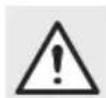
3.1 Mounting the stand
Fit the two supplied parts of the stand 10 into each other and slide the upper part to the left as shown below.
natural_image
Mechanical diagram showing two cross-sectional views of a bearing or bearing assembly with arrows indicating direction (no text or labels)Place the back of the unit on a stable table. The lower part of the housing must protrude slightly over the edge of the table.
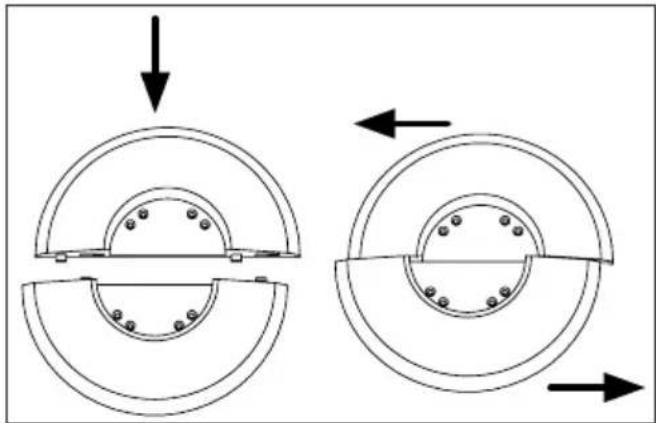
Place the stand 10 on the bottom of the housing. Four holes on the bottom of the housing fit exactly on four holes of the stand 10. Screw the stand 10 hand-tight with the four screws 11 supplied. Do not overtighten the screws 11!
natural_image
Technical line drawings of mechanical components, including a circular component with bolt holes and a multi-layered assembly (no text or symbols)■ Make sure that the stand 10 is straight and firmly attached to the housing.
■ Now place the unit on the stand 10.
3.2 Setting up the unit
For safe and fault-free operation of the unit, the installation site must meet the following requirements:
■ The floor must be firm, flat and horizontal.
■ Minimum distances from the housing of 90 cm to the side, 90 cm to the top, 90 cm to the rear and 1 m to the front must be maintained.
Do not place the unit in a hot, wet or very humid environment or near combustible material.
The power socket must be easily accessible so that the mains plug can be easily disconnected if necessary.
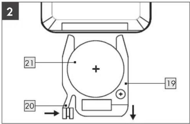
3.3 Remote control: Inserting/changing the battery
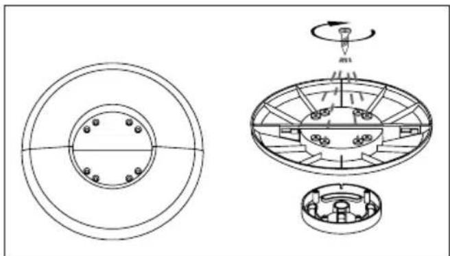
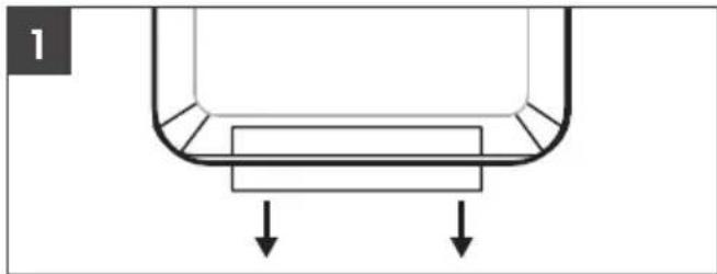
- When supplied, a lithium coin cell 21 is included with the remote control. In order to enable operation of the remote control, remove the plastic tape which protrudes out of the battery compartment 19 (see Image 1).
natural_image
Simple diagram of a U-shaped container with two downward arrows indicating flow or movement (no text or symbols)If the battery in the remote control has to be replaced, insert a new 3 volt lithium coin cell. Pay attention to the lithium coin cell type (CR2025) here.
Press the lock 20 on the remote controller battery compartment 19 to the centre. Then, pull the battery compartment 19 out (see Image 2).
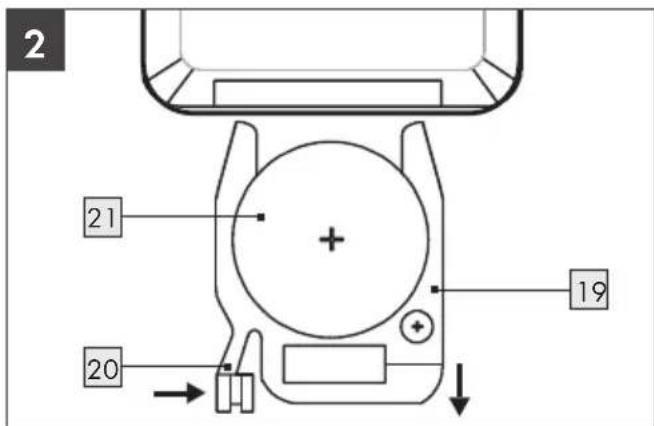
■ Remove the used battery 21.
- Insert a new type CR2025 3 volt lithium coin cell using the correct polarity.
■ Slide the battery compartment 19 back into the remote controller until the lock 20 clicks into position.
4. Start-up
ATTENTION!
The unit may only be put into operation after the stand 10 has been mounted.
Note: When using the appliance for the first time or after a long period of non-use, a slight odour may odour for a short time.
4.1 Standby mode
Connect the tower fan heater to an earthed, fused socket. Set the on/off switch 9 to the "I" position to supply power to the unit. The unit is now in standby mode and the display 1 shows the room temperature.
4.2 Ventilator-mode
In standby mode, press the on/off key ⏻ 4 / 18 once. The unit is now in fan mode. The symbol ♣ is shown on the display 1.
4.3 Heating level setting (heating mode)
In fan mode, press the heating level key 3/17 once. The unit is now in heating level 1. The tower fan heater provides a heating output of 1200 W. The symbol is shown on the display 1.
By pressing the heating level button ⏻ 3 / 17 again, the unit changes to heating level 2. The tower fan heater provides a heating output of 2000 W. The symbols ♠♦ are shown on the display 1.
4.4 Switching off the unit ⏻
To switch off the unit, press the on/off button 4 / 18 once.
- When the unit is in heating mode ( ♦ ♦ on the display 1 ), the fan continues to run for 30 seconds before it switches off (a countdown is shown on the display 1 ). After the countdown, the display 1 flashes three more times until a beep sounds.
If the unit is in fan mode ( ☐ on the display 1 ), no countdown appears on the display 1 after switching off.
■ The unit returns to standby mode.
■The Display 1 shows the room temperature.
- Set the on/off switch 9 to the "O" position to disconnect the tower fan heater from the power supply.
4.5 Oscillation function
In fan ⚙ or heating ⚠ mode, press the oscillation key ⏻ 7 / 16 to switch the oscillation of the unit on or off.
When successfully activated, the oscillation indicator lights up on the display 1.
The oscillation function causes the discharged air to be distributed from left to right.
4.6 Temperature setting
In fan ♣ or heating mode ♦, press the temperature key ⏻ 2 / 12 to enter the temperature setting mode.
Press the plus key + 6 / 13 (or the temperature key 2 / 12 itself) repeatedly to increase your desired temperature.
Press the minus button ⏻ 5 / 14 repeatedly to decrease the temperature you want.
You can select a temperature between 15 °C and 40 °C.
- Wait 3 seconds after setting the desired temperature. The setting is automatically accepted.
After successful temperature setting, the temperature indicator ⚫ on the display 1 lights up.
If the desired temperature is 2-3 degrees higher than the room temperature, one of the heating level indicators also lights up.
If the desired temperature is at least 4 degrees higher than the room temperature, both heating level indicators light up.
The integrated thermostat now switches the heating function on/off automatically.
ATTENTION! When setting the temperature, please note that the appliance will not heat if the desired temperature is lower than or equal to the room temperature. To heat, the set temperature must be at least 2 °C higher than the room temperature. The room temperature is automatically displayed when the unit is switched on.
Note: As long as the tower fan heater is in this mode, the fan continues to run permanently in the background.
If you want to make sure which temperature setting has been accepted, press the temperature key ⏻ 2 / 12 once. The temperature setting is shown flashing in the display 1 for 3 seconds.
4.7 Timer setting ©
The timer is used to automatically switch off the tower fan heater. The timer can be used to select a switch-off time in steps of one hour. The tower fan heater then switches off automatically.
■Infan or heating mode, press the timer key ⑧ / 15 to set the timer.
Press the Plus key +6 / 13 or the Minus key -5 / 14 repeatedly to set the desired switch-off time.
■ After setting the desired switch-off time, wait 3 seconds. The setting is automatically accepted.
■ The timer can be set in 1-hour steps:
$$ \begin{array}{l} 0 0 - 0 1 - 0 2 - 0 3 - 0 4 - 0 5 - 0 6 - 0 7 - 0 8 \ - 0 9 - 1 0 - 1 1 - 1 2 - 1 3 - 1 4 - 1 5 - 1 6 - 1 7 - \ 1 8 - 1 9 - 2 0 - 2 1 - 2 2 - 2 3 - 2 4 \end{array} $$
■ After successful timer setting, the timer indicator lights up on the display 1.
If you want to check which timer setting has been accepted, press the timer key ⑨ 8 / 15 once. Your entry flashes in the display 1 for 3 seconds.
NOTE: When the appliance is switched off or when you set the on/off switch 9 to the "O" position, the timer and the temperature you have set are reset.
5. Protective devices for the appliance
5.1 Overheating protection
This appliance is equipped with overheating protection. If the appliance becomes too hot, the heating element is automatically switched off. To switch the appliance off, set the on/off switch 9 to "O" and unplug the mains plug from the mains socket. Let the appliance cool down for at least 10 minutes.
ATTENTION! There's normally a reason for overheating! It can mean fire danger! Check whether the appliance can give off its heat sufficiently: Is the appliance covered or is it too close to an obstacle? If possible, rectify the problem. Even if you cannot find a cause, but overheating protection is triggered again, you must switch the appliance off and revert to the service hotline (see chapter "Service").
5.2 Tip-over protection
This appliance is equipped with overturning protection. If the appliance is accidentally knocked over or subjected to significant inclination during operation, it is automatically switched off. The appliance works exclusively in an upright position.
6. Maintenance, cleaning and storage
Always unplug the mains cable when the appliance is not in use, prior to each cleaning or in case of operational faults!
- Only clean the appliance when switched off and cold.
■ Ensure when cleaning that no moisture ingresses into the appliance in order to avoid irreparable damages to the appliance.
Only clean the housing of the unit and that of the remote control with a slightly damp, soft cloth. Do not use aggressive and/or abrasive cleaning agents.
■ Remove dust deposits on the protective mesh and on the ventilation louvres with a vacuum cleaner.
7. Disposal
The packaging consists of environmentally friendly materials which you can dispose of via local recycling points.


The Triman logo is valid in France only.
This product is subject to the European Directive 2012/19/EU. Do not dispose of the product in household waste, but via municipal collection points for material recycling! Further information on how to dispose of the discarded device can be obtained from your local authority or city council.

Batteries must be recycled in accordance with Directive 2006/66/EC and may not be disposed of with domestic waste. Each consumer is legally obliged to return all batteries/rechargeable batteries to a collection point in his municipality/district or to the trade. This duty serves to ensure that batteries/rechargeable batteries can be directed to environmentally friendly disposal. Only return batteries/rechargeable batteries which are not charged Batteries must be removed from the appliance prior to disposal.
Observe the markings on the packaging materials when separating the waste, they are marked with abbreviations (a) and numbers (b) with the following meanings: 1-7: Plastics/20-22: Paper and cardboard/80-98: Composite materials.
8. EU conformity

The tower heater blower meets the requirements of the valid European and national regulations.
9. ROWI Germany GmbH Warranty
Dear Customer,
This appliance has a 3-year warranty valid from the date of purchase. If this product has any faults, you, the buyer, have certain statutory rights. Your statutory rights are not restricted in any way by the warranty described below.
Warranty conditions
The validity period of the warranty starts from the date of purchase. Please keep your original receipt in a safe place. This document will be required as proof of purchase.
If any material or production fault occurs within three years of the date of purchase of the product, we will either repair or replace the product for you or refund the purchase price at our discretion. This
warranty service is dependent on you presenting the defective appliance and the proof of purchase (receipt) and a short written description of the fault and its time of occurrence.
If the defect is covered by the warranty, your product will either be repaired or replaced by us. The repair or replacement of a product does not signify the beginning of a new warranty period.
Warranty period and statutory claims for defects
The warranty period is not prolonged by repairs effected under the warranty. This also applies to replaced and repaired components. Any damage and defects present at the time of purchase must be reported immediately after unpacking. Repairs carried out after expiry of the warranty period shall be subject to a fee.
Scope of the warranty
This appliance has been manufactured in accordance with strict quality guidelines and inspected meticulously prior to delivery.
The warranty covers material faults or production faults. The warranty does not extend to product parts subject to normal wear and tear or fragile parts such as switches, batteries or those made of glass.
The warranty does not apply if the product has been damaged, improperly used or improperly maintained. The directions in the operating instructions for the product regarding proper use of the product are to be strictly followed. Uses and actions that are discouraged in the operating instructions or which are warned against must be avoided.
This product is intended solely for private use and not for commercial purposes. The warranty shall be deemed void in cases of misuse or improper handling, use of force and modifications/repairs which have not been carried out by one of our authorised Service centres.
Warranty claim procedure
To ensure quick processing of your case, please observe the following instructions:
Please have the till receipt and the item number (IAN 392286_2201) available as proof of purchase.
- You will find the item number on the type plate on the product, on the front page of the instructions (bottom left), or as a sticker on the rear or bottom of the appliance.
If functional or other defects occur, please contact the service department listed either by telephone or by e-mail.
- You can return a defective product to us free of charge to the service address that will be provided to you. Ensure that you enclose the proof of purchase (till receipt) and information about what the defect is and when it occurred.
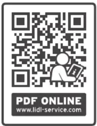
At www.lidl-service.com you can download this manual as well as many other manuals, product videos and installation software. This QR code will take you directly to the Lidl service page (www.lidl-service.com) and allow you to open your operating instructions simply by entering the article number (IAN 392286_2201).
10. Service
Should you incur any problems when operating your ROWI Germany product, please do the following:
Making contact
You can reach the ROWI Germany service team under:
ROWI Germany GmbH
(free from landlines)
IAN 392286_2201
Most problems can already be resolved by competent, technical advice from our service team.
natural_image
Mechanical diagram showing two cross-sectional views of a bearing or bearing assembly with arrows indicating direction (no text or labels)natural_image
Technical line drawing of a mechanical assembly with circular components and a multi-tiered top view (no text or symbols)natural_image
Simple diagram of a container with two downward arrows indicating flow or movement (no text or symbols)natural_image
Diagram showing two mechanical bearing assemblies with circular components and directional arrows indicating motion (no text or labels)natural_image
Technical line drawing of a mechanical assembly with circular components and a multi-layered exploded view (no text or symbols)natural_image
Simple diagram of a U-shaped container with two downward arrows indicating flow or movement (no text or symbols)5.1 Protection anti-surchauffe
WAARSCHUWING! Niet afdekken!
natural_image
Diagram showing two mechanical bearing assemblies with circular components and directional arrows indicating motion (no text or labels)natural_image
Technical line drawings of mechanical components including a circular housing, a rotating fan assembly, and a cross-sectional view (no text or symbols)natural_image
Simple diagram of a U-shaped container with two downward arrows indicating downward flow (no text or symbols)natural_image
Diagram showing two mechanical bearing assemblies with arrows indicating motion direction (no text or labels)natural_image
Technical line drawing of a mechanical assembly with circular components and a multi-tiered top view (no text or symbols)natural_image
Simple diagram of a U-shaped container with two downward arrows indicating flow or movement (no text or symbols)natural_image
Diagram showing two mechanical bearing assemblies with circular components and directional arrows indicating motion (no text or labels)natural_image
Technical line drawing of a mechanical assembly with circular components and a top view showing internal structure (no text or symbols)natural_image
Simple diagram of a U-shaped container with two downward arrows indicating downward flow (no text or symbols)natural_image
Diagram showing two mechanical bearing assemblies with circular components and directional arrows indicating motion (no text or labels)natural_image
Technical line drawing of a mechanical assembly with circular components and a central rotating component (no text or symbols)natural_image
Simple diagram of a U-shaped container with two downward arrows indicating downward flow (no text or symbols)natural_image
Diagram showing two mechanical bearing assemblies with circular components and directional arrows indicating motion (no text or labels)natural_image
Technical line drawing of a mechanical assembly with circular components and a rotating component (no text or symbols)natural_image
Simple diagram of a U-shaped container with two downward arrows indicating flow or movement (no text or symbols)natural_image
Technical diagram showing two mechanical bearing assemblies with mounting holes and directional arrows (no text or labels)natural_image
Technical line drawings of mechanical components, including a circular assembly and a multi-layered assembly with rotating parts (no text or symbols)natural_image
Simple diagram of a U-shaped container with two downward arrows indicating flow or movement (no text or symbols)natural_image
Mechanical diagram showing two cross-sectional views of a bearing or dial assembly with arrows indicating motion direction (no text or labels)natural_image
Technical line drawings of mechanical components including a circular housing, a multi-tiered fan assembly, and a multi-cylinder assembly (no text or symbols)natural_image
Simple diagram of a U-shaped container with two downward arrows indicating flow or movement (no text or symbols)natural_image
Mechanical assembly diagram showing two circular components with bolt holes and directional arrows indicating motion (no text or labels)natural_image
Technical line drawings of mechanical components including a circular component, a multi-layered assembly, and a multi-cylinder assembly (no text or symbols)natural_image
Simple diagram of a U-shaped container with two downward arrows indicating downward flow (no text or symbols)natural_image
Mechanical diagram showing two cross-sectional views of a bearing or dial assembly with arrows indicating direction (no text or labels)natural_image
Technical line drawings of mechanical components, including a circular component with bolt holes and a multi-circular assembly with rotating fan (no text or symbols)natural_image
Simple diagram of a U-shaped container with two downward arrows indicating downward flow (no text or symbols)Če je treba baterijo daljinskega upravljalnika zamenjati, vstavite novo 3-voltno litijevo gumbasto baterijo. Pri tem pazite, da uporabite ustrezno vrsto litijeve gumbaste baterije (CR2025). Potisnite spono 20 prostora za baterijo 19 daljinskega upravljalnika do sredine. Zdaj izvlecite prostor za baterijo 19 (glejte sliko 2).
- Odstranite izrabljeno baterijo 21.
Vstavite novo 3-voltno litijevo gumbasto baterijo vrste CR2025 glede na polarnost.
Potisnite prostor za baterijo 19 nazaj v daljinski upravljalnik, da se spona 20 zaskoči.