
221884 - Blender Hendi - Free user manual and instructions
Find the device manual for free 221884 Hendi in PDF.
| Product type | Professional immersion blender |
| Brand | Hendi |
| Model | 221884 |
| Power supply | 230 V / 50 Hz |
| Power | 350 W |
| Speed | 4,000 ~ 16,000 rpm |
| Weight (without accessory) | 2.35 kg |
| Dimensions (L × diameter) | 416 mm × 100 mm |
| Usage | Professional: restaurants, hotels, creameries |
| Main functions | Blend, emulsify, mix hot and cold foods: soups, purees, creams, sauces, mayonnaise |
| Compatible accessories | Mixing whisk (optional) and beater whisk (optional) – see manual |
| Lock function | Yes, for continuous operation |
| Overheat protection | Yes, automatic shutdown if overheated |
| Safety | Protection button, sharp blade, do not immerse motor |
| Maintenance | Unplug before cleaning; whisk washable with water, motor wiped with damp cloth |
| Warranty | 12 months manufacturing defects |
| Protection class | Class I |
| Body material | Plastic |
| Cable length | Not specified (standard estimate ~1.5 m) |
| Operating temperature | Indoor only |
| Spare parts available | Yes, via Hendi after-sales service |
Frequently Asked Questions - 221884 Hendi
User questions about 221884 Hendi
0 question about this device. Answer the ones you know or ask your own.
Ask a new question about this device
Download the instructions for your Blender in PDF format for free! Find your manual 221884 - Hendi and take your electronic device back in hand. On this page are published all the documents necessary for the use of your device. 221884 by Hendi.
USER MANUAL 221884 Hendi
natural_image
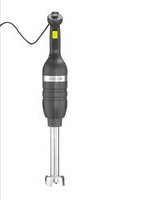
Two black electric shaver machines side by side, one with a yellow button and the other with a yellow label (no visible text or symbols)You should read this user manual carefully before using the appliance.
Keep these instructions with the appliance.
natural_image
Simple icon of a house with an arrow pointing left, labeled 'INDOOR' below (no other text or symbols)For indoor use only.


natural_image
Simple geometric pattern of concentric squares (no text or symbols)CE
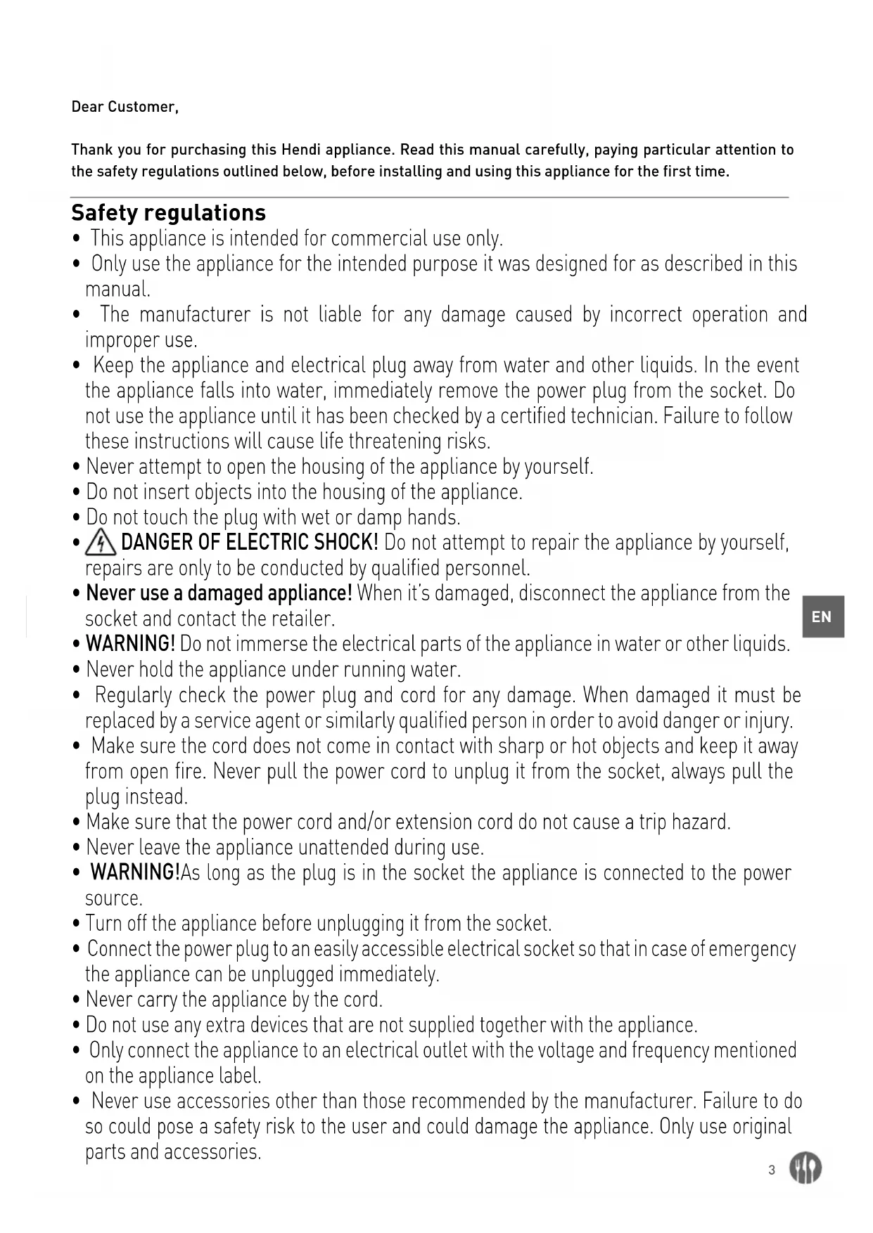
Thank you for purchasing this Hendi appliance. Read this manual carefully, paying particular attention to the safety regulations outlined below, before installing and using this appliance for the first time.
Safety regulations
- This appliance is intended for commercial use only.
- Only use the appliance for the intended purpose it was designed for as described in this manual.
- The manufacturer is not liable for any damage caused by incorrect operation and improper use.
- Keep the appliance and electrical plug away from water and other liquids. In the event the appliance falls into water, immediately remove the power plug from the socket. Do not use the appliance until it has been checked by a certified technician. Failure to follow these instructions will cause life threatening risks.
- Never attempt to open the housing of the appliance by yourself.
- Do not insert objects into the housing of the appliance.
- Do not touch the plug with wet or damp hands.
- DANGER OF ELECTRIC SHOCK! Do not attempt to repair the appliance by yourself, repairs are only to be conducted by qualified personnel.
- Never use a damaged appliance! When it's damaged, disconnect the appliance from the socket and contact the retailer.
- WARNING! Do not immerse the electrical parts of the appliance in water or other liquids.
- Never hold the appliance under running water.
- Regularly check the power plug and cord for any damage. When damaged it must be replaced by a service agent or similarly qualified person in order to avoid danger or injury.
- Make sure the cord does not come in contact with sharp or hot objects and keep it away from open fire. Never pull the power cord to unplug it from the socket, always pull the plug instead.
- Make sure that the power cord and/or extension cord do not cause a trip hazard.
- Never leave the appliance unattended during use.
- WARNING! As long as the plug is in the socket the appliance is connected to the power source.
- Turn off the appliance before unplugging it from the socket.
- Connect the power plug to an easily accessible electrical socket so that in case of emergency the appliance can be unplugged immediately.
- Never carry the appliance by the cord.
- Do not use any extra devices that are not supplied together with the appliance.
- Only connect the appliance to an electrical outlet with the voltage and frequency mentioned on the appliance label.
-
Never use accessories other than those recommended by the manufacturer. Failure to do so could pose a safety risk to the user and could damage the appliance. Only use original parts and accessories.
-
This appliance should not be operated by persons with reduced physical, sensory or mental capabilities, or persons that have a lack of experience and knowledge.
- This appliance should, under any circumstances, not be used by children.
- Keep the appliance and its power cord out of reach of children.
- WARNING: ALWAYS switch off the appliance and unplug from power socket before cleaning, maintenance or storage.
Special Safety Regulations
- Use the appliance only as described in this manual. Indoor use only.
- This appliance should be operated by trained personnel.
- Never let the blade face towards anybody while operating the appliance.
- Do not touch the blade and moving parts. Keep fingers, hair, clothing and utensils away from all moving parts.
- Dry the appliance and all accessories before connecting to the power supply and prior to attaching the accessories.
- DANGER OF HAND INJURY! Handle the blade with great care as it is very sharp.
- Never add ingredients to the container while the appliance is operating.
- WARNING! Unplug immediately after use, before removing or changing accessories.
- This product is a hand-held appliance designed to process foodstuff in a container.
- All maintenance, installation and repair works should be performed by specialized trained authorized technicians.
- WARNING: During operation, keep hands and utensils out of the container to reduce the risk of severe personal injury and / or damage to the blender.
- Do not continuously operate the appliance to avoid overheating the motor. The continuous operation time should not exceed over 3 minutes. Operate the appliance again, after it has been cooled.
- Do not wash the appliance with water or waterjet. Washing with water can cause leakage and increase the risk of electric shock. No parts are dishwasher safe.
- Lay out the power cord in such a way that no unintentional pulling or tripping over is possible.
- Do not clean or store the machine unless it is completely cooled down.
- This appliance is classified as protection class II.
For mounting the wall bracket of item 222393 on the wall, please read carefully below important safety precautions:
• Installation should be done by the qualified technician for the reason of safety.
- Verify prior to installation that the wall can safely support the loading of whole set of appliance & its accessories.
- Make sure that no electrical wires, water, gas or other lines are located around the installation location.
- Consult a qualified contractor or installer for assistance if you are not certain about the structure of the wall.
- Tighten the screws firmly but do not over tighten. Over tightening can damage the screws, greatly reducing the holding power.
- During installation, keep away the pet and children.
- WARNING! Do not put other things except the appliance to prevent overloading of the bracket.
Intended use
- The appliance is intended for professional use.
- This appliance is intended only for pureeing, emulsifying and mixing hot and cold food commercially. It allows for preparation of soups, puree, creams, marzipan mass, cheese creams, etc. directly in the pot. Any other use may lead to damage to the appliance or personal injury.
- Operating the appliance for any other purpose shall be deemed a misuse of the appliance. The user shall be solely liable for improper use of the appliance.
Product description

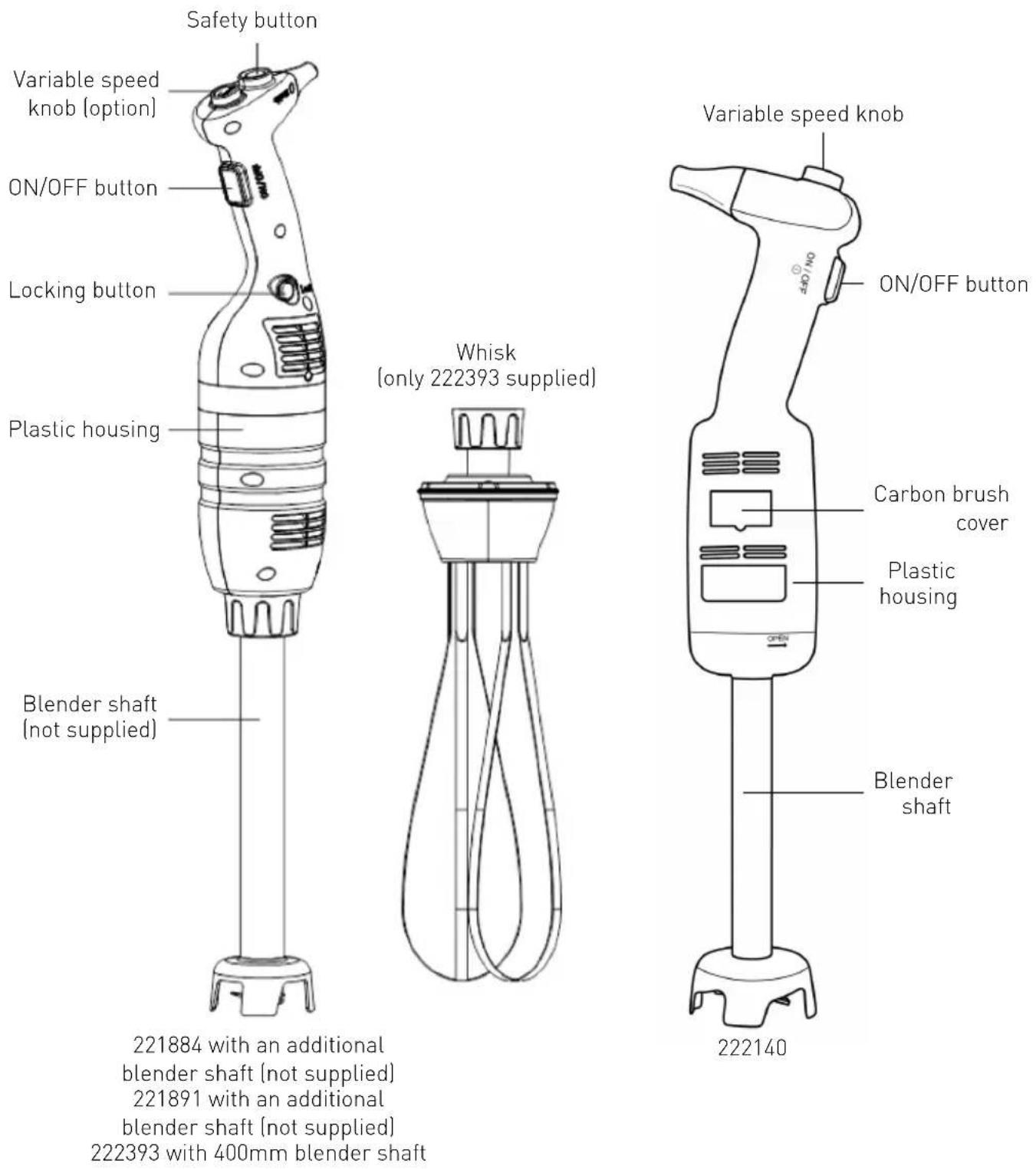
221884 with an additional blender shaft (not supplied)
221891 with an additional blender shaft (not supplied)
222393 with 400mm blender shaft
Main technical parameters
Model: 222140 Model: 221884 / 221891
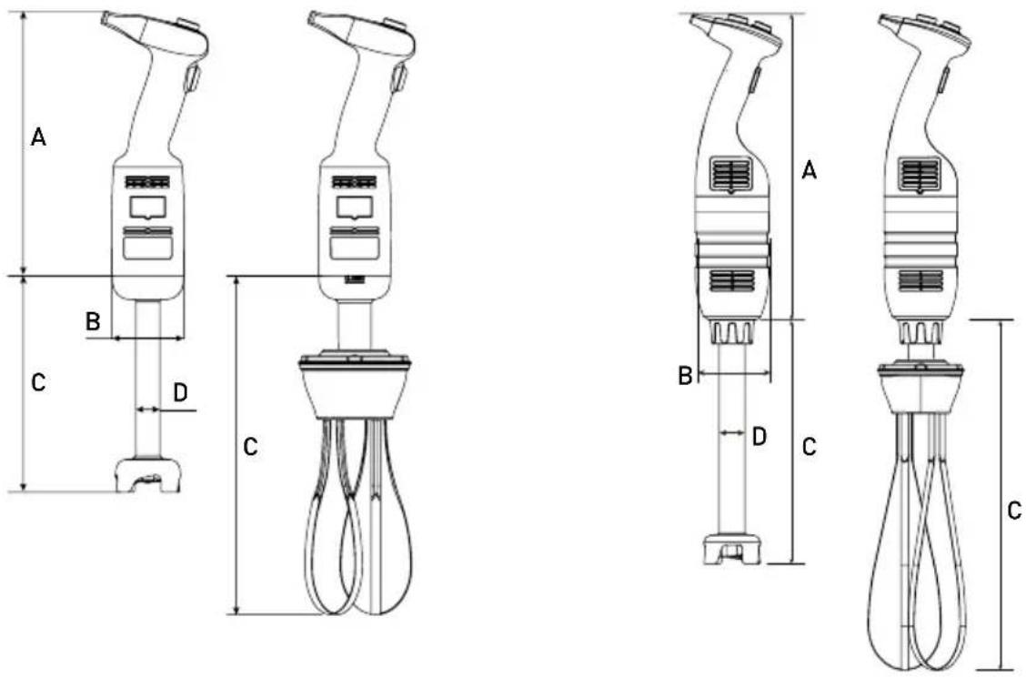
Technical Specifications
| Code Supply voltage | Power Approx. rotation speed | Approx. weight of main unit excluding blending shaft or whisk | A (Length) | B (Diameter) | ||
| 222140 | 230 V/50 Hz | 220 W | 4,000 ~ 20,000 rpm | 1,15 kg | 304 mm | ∅ 75 mm |
| 221884 | 230 V/50 Hz | 350 W | 4,000 ~ 16,000 rpm | 2,35 kg | 416 mm | ∅ 100 mm |
| 221891 | 230 V/50 Hz | 500 W | 4,000 ~ 16,000 rpm | 2,55 kg | 416 mm | ∅ 100 mm |
Remark: Technical specifications are subject to change without prior notice.
Combination table for the Blender shaft and whisk accessories. Below accessories are not included:
| Code Approx. weight | C (Length) | D (Diameter) | Description | |
| 222164 | 0,81 kg | 185 mm | - | Whisk for 222140 (optional) |
| - | 0,52 kg | 160 mm | ∅ 28 mm | Blender shaft for 222140 (supplied) |
| 222263 | 0,86 kg | 250 mm | - | Whisk for model 221884 (optional) and 221891 (optional) |
| 222225 | 0,82 kg 250 mm | ∅ 35 mm | Blender shaft for 221884 (optional) and 221891 (optional) | |
| 222232 | 1,02 kg | 300 mm | ∅ 35 mm | |
| 222249 | 1,28 kg | 400 mm | ∅ 35 mm | |
| 222256 | 1,56 kg | 500 mm | ∅ 35 mm | |
Remarks: Set of item 222393 = 221884 + 222249 + 222263 + wall bracket + installation kits (2 sets of mounting screws, washers and expansion bolts).
Introduction
- Read this Operation Manual carefully before using the appliance. It contains important for your safety as well as operating and maintenance advice.
- This appliance is for professional use in ice-cream shops, restaurants, hotel kitchens for preparing ice-cream mixes, vegetable soups, purees, sauces, stuffing, mayonnaise, tomato paste, pesto, etc.
- If you wish to make the best use of the stick blender functions, you must be thoroughly familiar with its performance and operating features.
- Maintenance requires just a few simple operations that may be performed by the operator.
- To ensure a long life and minimize operating costs, follow the instructions given in this manual.
-
The manufacturer has designed the Immersion Blender to ensure safe operating conditions. Removal of protections installed by the manufacturer will seriously undermine the guaranteed safety conditions.
-
To ensure safety, comply with the instructions regarding installation and connection of the device to the power supply.
- The device must be installed in a work environment free of corrosive agents.
- The installation area must not be potentially explosive.
- Use only supplied SPARE PARTS.
- This Operation Manual is an integral part of the Immersion Blender and must be kept in a safe place. The features, information and drawings published herein are the exclusive property of the manufacturer.
- The appliance functions make it possible to prepare in the minimum time the following types of food: thick vegetable purees, soups, mashed potatoes, creams, batters, doughs, mayonnaise, almond pulp, cream cheese etc.
Preparations before bracket mounting on the wall (For item: 222393 only)
EN
Before installation: Check the wall bracket for any damage & the completeness of the installation kits (2 set of mounting screws, washers and expansion bolts included). DO NOT install if any missing or damage.
Note:
- Consult a qualified contractor or installer for assistance if you are not certain about the structure of the wall and ensure that the procedure is carried out properly and safely.
- Installation work should be done by qualified technicians for the reason of safety.
- The distance between the holes of mounting screws is about 217mm. Make clear the surrounding before installation.
-
Important: Before starting bracket mounting on the wall, make sure you have all the tools, such as screw driver, electric drills, measuring tape, marking pencil (All are not included).
-
The bracket must be securely anchored on a wall by attaching two mounting screws with the expansion bolts inserted.
- Be aware of the items such as ducts, electrical wires and water pipes that hide behind the walls in your work area. Special care is required during installation.
Operating instructions (Model: 222140)
CAUTION: Before connecting the appliance to the power supply, check that the power supply voltage corresponds with the power supply details shown on the rating label.
REMARK: There is no lock function for continuous operation for this model 222140.
Operating the appliance:
- Ensure that the appliance is disconnected from the power supply before assembly.
- Connect the blending shaft/whisk to the main unit.
- Check that the ON/OFF button (1) is in the released (flat) position.
- Connect the appliance to the power supply.
- Then, press the ON/OFF button (1). The appliance will turn on. BE CAREFUL!
- To turn off the appliance, release the ON/OFF button (1).
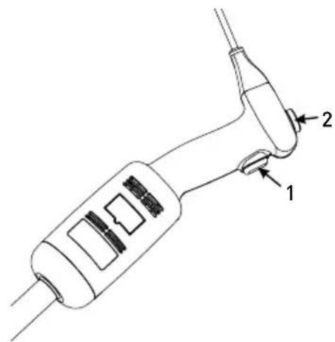
Operating instructions (Model: 221884, 221891, 222393)
CAUTION: Before connecting the appliance to the power supply, check that the power supply voltage corresponds with the power supply details shown on the rating label.
REMARK: There is lock function for continuous operation for the model 221884 & 221891.
Starting and stopping the appliance
- Ensure that the appliance is disconnected from the power supply before assembled.
- Connect the blending shaft/whisk to the main unit.
- Check that the ON/OFF button (3) is in the released (flat) position.
- Connect the appliance to the power supply.
- Press and hold the Safety button (1) first.
- Then, press the ON/OFF button (3) at the same time. The appliance will start up. BE CAREFUL!
- Release the Safety button (1), the appliance will keep operating.
- To stop the appliance, release the ON/OFF button (3).
Continuous operating the appliance:
Follow steps 1 to 7 above, then:
- With the ON/OFF button (3) in "pressed" position, press Locking button (4) once.
- Release the ON/OFF button (3) and the appliance will keep operating in a continuous mode.
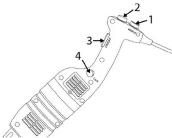
- To turn off the appliance, press and release the ON/OFF button (3).
Variable speed operation (Model: 222140, 221884, 221891, 222393)
Follow steps 1 to 7 above, then:
- Change the speed of the motor by turning the variable speed button (2) towards the maximum or minimum as required. It is advisable to start the device at a low speed when using the whisk.
REMARKS:
Blender function: For better control, we recommend you hold the bender by the handle and the bottom of the motor unit. Furthermore, we recommend you tilt the bender slightly to prevent the bell from touching the bottom of the container. Always make sure that the bell is sufficiently immersed to avoid splashing and that the air vents of the motor unit do not come into contact with any liquid. For optimum efficiency, two-thirds of the blending arm should be immersed in the mixture being prepared.
With the self-regulating speed system, the selected speed will remain constant even if the consistency of your mixture changes.
Whisk function: You can also hold the device with one hand the bowl with the other hand if necessary. During operation we recommend you move the whisk around in the bowl in order to ensure that the mixture is completely homogeneous. Keep the whisk away from the sides of the bowl. For maximum efficiency, at least one-fifth of the whisk length should be immersed. Never immerse the whisk holder in the mixture.
Assembling / Disassembly of the attachments
The assembly / disassembly operations of the appliance are performed with the appliance stopped and disconnected from the power supply.
Assembly: Model 222140:
- Align and insert the coupling (5) of the blending shaft (3) or the whisk (6) in the clutch (2) of the main unit (1).
- Screw thoroughly the blending arm (3) or whisk (6) to the main unit (1).
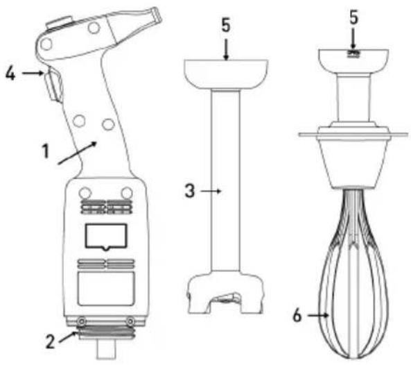
Assembly: Model 221884, 221891, 222393:
- Align and insert the coupling (5) of the blending shaft (3) or the whisk (4) in the clutch (2) of the main unit (1). Make sure the narrower part of the appliance coupling fits the concave side of the blender shaft (3) or whisk (4) arm coupling.
- Screw the nut (6) up to fasten it firmly to the main unit (1).
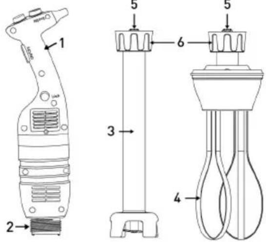
Follow the above steps in the reverse order to disassembly the accessories.
Cleaning instructions
Before cleaning always unplug the appliance form the source of power supply.
• After using the Stick Blender in a hot mixture, cool the blending shaft in cold water before dismantling the bell from the blender shaft. Clean the shaft immediately after use to prevent adhesion of the mixture.
- Never immerse the motor unit or the handle in water; clean with a damp cloth or a sponge.
- Blender shaft and bell cleaning: Place the blending arm and the bell in a suitable container with clean water and switch on for a few seconds.
- WARNING: Always dry the blades thoroughly after cleaning to avoid rust spotting.
- Never immerse the whisk holder in water; clean with a damp cloth or a sponge.
• After use clean the appliance with a detergent or disinfectant. Do not use undiluted bleach. Do not use alkaline detergents to clean plastic parts.
Troubleshooting
In case of a power cut or if the device has been unplugged, release the ON/OFF button (3), check the power supply and restart the device.
If the device is switched off due to overheating, release the ON/OFF button (3), and unplug the device, wait a few minutes for the motor to cool down and the thermal safety mechanism to be reset, and then restart the device.
If the cause of the problem cannot be determined: release the ON/OFF button (3), unplug the device, check below:
- the plug
- that the blades are free to rotate in the bell,
- that state of the power cord,
- the drive shaft is free to rotate. To this end, remove the bell and test the rotation of the end of the drive shaft manually.
If a malfunction occurs which is listed in this operation manual, consult your retailer or return the device to the after-sales service.
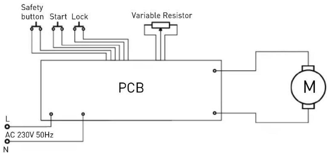
Electrical diagram
Model 222140


flowchart
graph LR
    A["AC230V"] --> B["Switch"]
    B --> C["PCB"]
    C --> D["M"]
    D --> E["Motor"]
    F["Variable Resistor"] --> C
    G["AC230V"] --> H["Switch"]
    I["AC230V"] --> J["Switch"]
Model 221884, 221891, 222393
Exploded drawing & part list for model 222140
Model 222140
Part list - model 222140 main unit and blender shaft
| Part No. | Part Name Part | No. | Part Name Part | No. | Part Name |
| 1 | Blade | 14 | Plastic head housing | 26 | Pressing board screw |
| 2 | Convex ring | 15 | Spline sleeve | 27 | Switch osculant staff |
| 3 | Graphite ring spring | 16 | Bearing | 28 | Housing screw |
| 4 | Graphite ring | 17 | Rotor | 29-1 | Screw plunger 28-1 |
| 5 | Ceramic ring | 18 | Brush barrel | 29-2 | Screw plunger 28-2 |
| 6 | Ceramic ring sleeve | 18-1 | Brush cover | 29-3 | Screw plunger 28-3 |
| 7 | Knife protector | 19 | Brush | 29-4 | Screw plunger 28-4 |
| 8 | Bearing sleeve | 20 | Stator | 29-5 | Screw plunger 28-5 |
| 9 | Seal ring | 21 | PCB Speed control board | 29-6 | Screw plunger 28-6 |
| 10 | W688Z Bearing | 22 | Left and right housing | 30 | Cable sheath |
| 11 S/S tube 23 | Rubber interlocking protector | 31 | Power cord | ||
| 12 | Output axis | 24 | Pressing board | ||
| 13 | Spline | 25 | Speed control key | ||
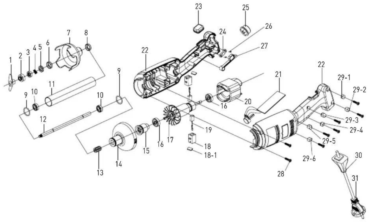
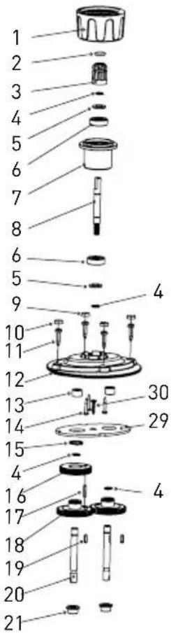
Exploded drawing & part list for model 221884, 221891, 222393 (Main unit only)

Part list - model 221884, 221891, 222393 (main unit only)
Part No. Part Name Part No. Part Name Part No. Part Name
| 1 | Power cord | 10 | Air outlet cover | 19 | Ring |
| 2 | Cable tie | 11 | Pressing board screw | 20 | Air outlet cover |
| 3 | Switch | 12 | Housing 2 | 21 | Housing 4 |
| 4 | Pressing board screw | 13 | Spline sleeve | 22 | Locking button |
| 5 | Pressing board screw | 14 | Bottom motor cover | 23 | Switch osculant staff |
| 6 | PCB control panel | 15 | Motor | 24 | Switch sheath |
| 7 | Housing 1 | 16 | Upper motor cover | 25 | Pressing board |
| 8 | Screw plunger | 17 | Pressing board screw | 26 | Speed control key |
| 9 | Pressing board screw | 18 | Housing 3 | 27 | Safety button |
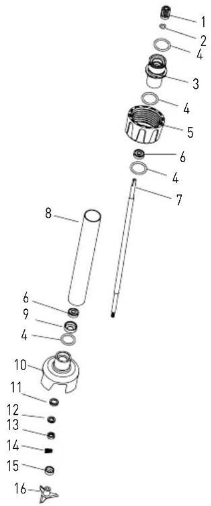
Part list - blender shafts (optional): 222225, 222232, 222249, 222256
| Part No. | Part Name Part | No. | Part Name Part | No. | Part Name |
| 1 Spline sleeve 7 Output axis (Different length | depend on different model) | 13 Graphite ring | |||
| 2 Spline sleeve seal ring 8 | 304 S/S tube (Different length depend on different model) | 14 Graphite ring spring | |||
| 3 | Connect sleeve | 9 | Bearing sleeve | 15 | Convex ring |
| 4 | Connect sleeve seal ring | 10 | Knife protector | 16 | Blade |
| 5 | Fastening sleeve | 11 | Ceramic ring sleeve | ||
| 6 608 bearing | 12 Ceramic ring | ||||
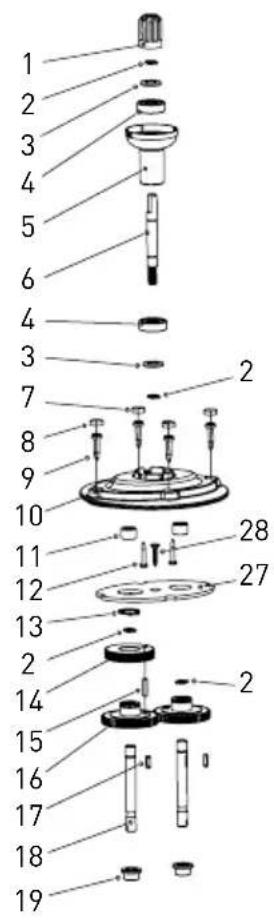
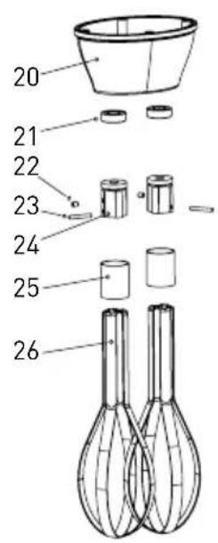
Part list - whisk (optional): model 222164
| Part No. | Part Name Part | No. | Part Name Part | No. | Part Name |
| 1 | Spline sleeve | 11 | Needle bearing | 21 | Oil sealing |
| 2 | ∅8 Snap ring | 12 | Screw | 22 | M4x5 Screw |
| 3 | Bearing washer | 13 | ∅16 Snap ring | 23 | Cylindrical pin |
| 4 | Bearing | 14 | Helical gear bearing | 24 | Fixed board |
| 5 | Connect sleeve | 15 | Cylindrical pin | 25 | Steel ring |
| 6 | Helical gear bearing | 16 | Straight gear | 26 | Steel bar |
| 7 | Screw plunger 2 | 17 | Key | 27 | Baffle plate |
| 8 | Screw plunger 1 | 18 | Output axis | 28 | Screw |
| 9 Housing screw | 19 Shaft sleeve | ||||
| 10 | Upper cover | 20 | Lower cover | ||
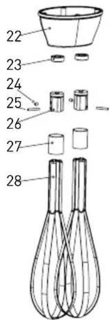
Part list – whisk (optional): model 222263
| Part No. | Part Name Part | No. | Part Name Part | No. | Part Name |
| 1 | Fastening sleeve | 11 | Housing screw | 21 | Shaft sleeve |
| 2 | Spline sleeve seal ring | 12 | Upper cover | 22 | Lower cover |
| 3 | Spline sleeve | 13 | Needle bearing | 23 | Oil sealing |
| 4 | ∅8 Snap ring | 14 | Screw | 24 | M4x5 Screw |
| 5 | Oil sealing | 15 | ∅16 Snap ring | 25 | Cylindrical pin |
| 6 | Bearing | 16 | Helical gear bearing | 26 | Fixed board |
| 7 | Connect sleeve | 17 | Cylindrical pin | 27 | Steel ring |
| 8 | Helical gear bearing | 18 | Straight gear | 28 | Steel bar |
| 9 | Screw plunger 2 | 19 | Key | 29 | Baffle plate |
| 10 | Screw plunger 1 | 20 | Output axis | 30 | Screw |
Warranty
Any defect affecting the functionality of the appliance which becomes apparent within one year after purchase will be repaired by free repair or replacement provided the appliance has been used and maintained in accordance with the instructions and has not been abused or misused in any way. Your statutory rights are not affected. If the appliance is claimed under warranty, state where and when it was purchased and include proof of purchase (e.g. receipt).
In line with our policy of continuous product development we reserve the right to change the product, packaging and documentation specifications without notice.
Discarding & Environment
When decommissioning the appliance, the product must not be disposed of with other household waste. Instead, it is your responsibility to dispose to your waste equipment by handing it over to a designated collection point. Failure to follow this rule may be penalized in accordance with applicable regulations on waste disposal. The separate collection and recycling of your waste equipment at the time of disposal will help conserve natural resources and ensure that it is recycled in a manner that protects human health and the environment.
For more information about where you can drop off your waste for recycling, please contact your local waste collection company. The manufacturers and importers do not take responsibility for recycling, treatment and ecological disposal, either directly or through a public system.
DAUERBETRIEB:
Teileliste - mixstäbe (optional): 222225, 222232, 222249, 222256
Teileliste - mixstab (optional): modell 222164
Teileliste - mixstab (optional): modell 222263
HET APPARAAT CONTINU GEBRUIKEN:
Montage van model 221884, 221891, 222393:
Praca ciągła:
Montaż: Modele 221884, 221891, 222393:
Mode d'emploi (modeles 221884, 221891, 222393):
FR
Liste des pieces – fouets mixeurs (options): 222225, 222232, 222249, 222256
Istruzioni d'uso (modelli: 221884, 221891, 222393):

LAVORO CONTINUO:
IT
Asamblare: Modelele 221884, 221891, 222393:
Lista componentelor - tije de amestecare (optional): 222225, 222232, 222249, 222256
RU
НЕПРЕРЫВНАЯ РАБОТА:
RU
Meets the essential requirements as described in: /
Meets the requirements as described in regulations: /
Meets the requirements as described in resolutions: /
Meets the essential requirements as described in: /
Has been engineered and manufactured in conformity to harmonized standards: /
Meets the requirements as described in regulations: /
Meets the requirements as described in resolutions: /
Technical documentation available at the company's headquarters: /
Hendi Food Service Equipment GmbH
Ehring 15
Hendi Food Service Equipment Romania S.R.L.
PKS Hendi South East Europe SA
5 Metsovou Str.
18346 Moschato, Athens, Greece
Tel: +30 210 4839700
Email: info@pks-hendi.com
Hendi Italia S.R.L.
Via Leonardo da Vinci 4
39100 Bolzano (BZ), Italy
Tel: +39 800 727 438
Email: office.italy@hendi.eu
Hendi HK Ltd.
1208, 12/F, Exchange Tower
33 Wang Chiu Road, Kowloon Bay, Hong Kong
Tel: +852 2154 2618
Email: info-hk@hendi.eu
Find Hendi on internet:
www.hendi.eu
www.facebook.com/HendiToolsforChefs
www.linkedin.com/company/hendi-food-service-equipment-b.v.
www.youtube.com/HendiEquipment
- Changes, printing and typesetting errors reserved.


- Safety regulations
- Special Safety Regulations
- Intended use
- Main technical parameters
- Introduction
- Preparations before bracket mounting on the wall (For item: 222393 only)
- Note:
- Operating instructions (Model: 222140)
- Operating the appliance:
- Operating instructions (Model: 221884, 221891, 222393)
- Starting and stopping the appliance
- Continuous operating the appliance:
- Variable speed operation (Model: 222140, 221884, 221891, 222393)
- Follow steps 1 to 7 above, then:
- REMARKS:
- Assembling / Disassembly of the attachments
- Assembly: Model 222140:
- Assembly: Model 221884, 221891, 222393:
- Cleaning instructions
- Troubleshooting
- Electrical diagram
- Exploded drawing & part list for model 222140
- Warranty
- Discarding & Environment
- DAUERBETRIEB:
- HET APPARAAT CONTINU GEBRUIKEN:
- Montage van model 221884, 221891, 222393:
- Praca ciągła:
- Montaż: Modele 221884, 221891, 222393:
- Mode d'emploi (modeles 221884, 221891, 222393):
- FR
- Istruzioni d'uso (modelli: 221884, 221891, 222393):
- LAVORO CONTINUO:
- Asamblare: Modelele 221884, 221891, 222393:
- RU
- НЕПРЕРЫВНАЯ РАБОТА:
- Hendi Food Service Equipment GmbH
- Hendi Food Service Equipment Romania S.R.L.
- PKS Hendi South East Europe SA
- Hendi Italia S.R.L.
- Hendi HK Ltd.
- Find Hendi on internet:
Brand : Hendi
Model : 221884
Category : Blender